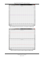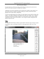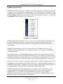
1
Digital BUS-WATCH® PC Software Manual Digital ® BUS-WATCH PC Software Manual BUS-WATCH® Live View And BUS-WATCH® Play Back Applications For BUS-WATCH® Mobile DVRs Radio Engineering Industries, Inc. 640372 - Rev D - 12/15/2010 Page 1 of 99 Digital BUS-WATCH® PC Software Manual Table of Contents Table of Contents ..................................................................................................... 2 Software Installation ................................................................................................ 5 Minimum Requirements ..........................................................................................................5 Recommended Requirements ..................................................................................................5 Setup .......................................................................................................................... 6 General Overview ........................................................................................................................6 Supported Hardware ....................................................................................................................6 BUS-WATCH® Software ....................................................................................... 7 Live View Application ............................................................................................. 8 Overview ......................................................................................................................................8 Menu Selection ............................................................................................................................8 Setup (Add DVRs) ...............................................................................................................9 Control (Remote Access) ...................................................................................................10 Show OSD / Hide OSD......................................................................................................11 Show Info Box / Hide Info Box .........................................................................................11 Help (User’s Manual) ........................................................................................................12 About..................................................................................................................................12 Play Back ...................................................................................................................................12 Map ............................................................................................................................................12 Chart...........................................................................................................................................13 Info .............................................................................................................................................16 DVR Information Display......................................................................................................16 Snap ...........................................................................................................................................17 Audio .........................................................................................................................................18 Record ........................................................................................................................................18 Video Capture ........................................................................................................................18 View Selection ...........................................................................................................................19 Window Configuration ..........................................................................................................20 Exit .............................................................................................................................................21 Channel Assignment ..................................................................................................................21 Single Device .........................................................................................................................21 Multiple Devices ....................................................................................................................22 Window Setup Function ....................................................................................................22 Close / Close All Functions ...............................................................................................26 Open Window / Open All Functions .................................................................................26 Clear Window / Clear All Functions .................................................................................26 Full Screen .........................................................................................................................27 Play Back Application ........................................................................................... 28 Overview ....................................................................................................................................28 Source Selection ........................................................................................................................28 Remote DVR connection ...................................................................................................29 Captured Video connection................................................................................................29 Mobile DVR (Network Connection)......................................................................................32 Radio Engineering Industries, Inc. 640372 - Rev D - 12/15/2010 Page 2 of 99 Digital BUS-WATCH® PC Software Manual DVR Remote Management System Captured Video .............................................................35 Hard Drive Module (local connection) ..................................................................................36 Smart Disk (local connection) ...............................................................................................37 Backup Video File .................................................................................................................37 Date/Time Selection ..................................................................................................................38 Calendar .................................................................................................................................38 Video Segment List ................................................................................................................38 View Selection ...........................................................................................................................39 Window Configuration ..........................................................................................................40 Full Screen View ....................................................................................................................40 Title Button ............................................................................................................................40 Info Button .............................................................................................................................41 DVR Information Display......................................................................................................42 Playback Control........................................................................................................................42 Progress Ticker ......................................................................................................................42 Progress Bar ...........................................................................................................................42 File View ............................................................................................................................43 Day View ...........................................................................................................................43 Direct Indexing ......................................................................................................................44 Playback Controls ..................................................................................................................45 Pause / Play Button ............................................................................................................45 Pervious Frame / Next Frame Buttons ...............................................................................46 Previous File / Next File Buttons .......................................................................................46 Stop Play Button ................................................................................................................46 Playback Speed Control .....................................................................................................47 Volume Control / Audio Enable Button ............................................................................47 Chart...........................................................................................................................................47 Video Editing Box .....................................................................................................................50 Snap (Snap Picture) Button ....................................................................................................50 Edit Clip Button .....................................................................................................................51 Add Clip and Delete Clip Buttons .........................................................................................52 BUS-TRACKERTM GPS Mapping ....................................................................... 54 Overview ....................................................................................................................................54 BUS-TRACKERTM Features .....................................................................................................54 GPS Map Icons ..........................................................................................................................55 Arrow Icon .............................................................................................................................56 Pan Icon .................................................................................................................................56 Zoom Out Icon .......................................................................................................................56 Zoom In Icon ..........................................................................................................................56 Bus Center Icon ......................................................................................................................57 Full Screen Map Icon .............................................................................................................57 Refresh Icon ...........................................................................................................................57 Title Bar Icon .........................................................................................................................57 Help Icon ................................................................................................................................57 GPS Map Tools ..........................................................................................................................57 Map Button ............................................................................................................................58 Map Setup Button ..................................................................................................................58 Radio Engineering Industries, Inc. 640372 - Rev D - 12/15/2010 Page 3 of 99 Digital BUS-WATCH® PC Software Manual Route Button ..........................................................................................................................58 Breadcrumb Button ................................................................................................................59 Route Event Button ................................................................................................................59 Route Filter Button ................................................................................................................59 Network Setup ........................................................................................................ 60 Setup ......................................................................................................................................60 Devices tab .............................................................................................................................60 DVR Groups ......................................................................................................................61 DVR Information ...............................................................................................................63 User Setup ..................................................................................................................................65 System ........................................................................................................................................66 Connect ..................................................................................................................................66 Record Capture Drivers .........................................................................................................66 Disk Setup ..........................................................................................................................67 Register Server .......................................................................................................................68 Remote Control ...................................................................................................... 69 Restart Device ........................................................................................................................72 Configure Device ...................................................................................................................72 Update Firmware ...................................................................................................................75 Format HDD ..........................................................................................................................75 Log View ...............................................................................................................................77 Restart All DVRs ...................................................................................................................77 Config All DVRs ...................................................................................................................77 Update All Firmware .............................................................................................................77 Format All HDD ....................................................................................................................77 View All Logs ........................................................................................................................77 Video Backup.......................................................................................................... 80 Backup Setup tab ...................................................................................................................80 File Backup tab ......................................................................................................................82 Multi-file Backup ...............................................................................................................82 Add File function ...............................................................................................................86 Backup Queue ....................................................................................................................86 Backup Log ........................................................................................................................88 Time Span Backup tab ...........................................................................................................89 File Conversion tab ................................................................................................................92 Direct Video Segment Backup ...............................................................................................93 Image Viewer .......................................................................................................... 95 Image Capture ........................................................................................................................95 Save Button ............................................................................................................................96 Open Button ...........................................................................................................................96 Text Button ............................................................................................................................96 Full Size .................................................................................................................................97 Most Suitable Button .............................................................................................................97 Print Button ............................................................................................................................97 Zoom Slide Bar ......................................................................................................................98 Image Qualities ......................................................................................................................98 Radio Engineering Industries, Inc. 640372 - Rev D - 12/15/2010 Page 4 of 99 Digital BUS-WATCH® PC Software Manual Software Installation Minimum Requirements Operating System: Windows XP SP3/ Windows Vista SP2 / Windows 7 Processor: Dual Core CPU Memory: 1 GB RAM Hard Disk Space: 10 GB free CDROM drive required for disc-based installation. 10/100 Base-T Network Interface Card / Controller (for Remote connections) USB 2.0 controller (minimum 2 ports available) Video: 128 MB ATI HD2600 XT or better, 128 MB NVidia 7900 GS or better, or Core i3 or better integrated graphics (non-shared) , generic video drivers are not supported LCD or CRT monitors supporting 1024 X 768 resolutions and higher Sound: DirectX 9.0c-compatibile sound card DirectX: DirectX version 9.0c Recommended Requirements Operating System: Windows 7 Processor: 1.8 GHz Quad Core CPU Memory: 4 GB RAM Hard Disk Space: 100 GB free DVDROM drive required for disc-based installation. DVD±R Drive recommended for video transfer. 10/100 Base-T Network Interface Card / Controller USB 2.0 controller (multi-port) Video: 512 MB ATI 4800 series or better, 512 MB NVidia 9800 series or better, generic video drivers are not supported LCD or CRT monitors supporting 1024 X 768 resolutions and higher Sound: DirectX 9.0c-compatibile sound card DirectX: DirectX version 11 Radio Engineering Industries, Inc. 640372 - Rev D - 12/15/2010 Page 5 of 99 Digital BUS-WATCH® PC Software Manual Setup To install the Digital BUS-WATCH® PC Software application suite, locate the setup file, Setup.exe, in the root directory of the installation media. Double-click the setup file to begin installation. It may begin the installation automatically upon insertion of the media if the host PC is set for auto-run. Follow the installation steps provided on-screen by the installation wizard to complete the installation of the software. As a hint just click the Next button whenever it can be pressed. For assistance with installation, setup, configuration or other technical support, please contact one of Radio Engineering Industries, Inc.’s support technicians at (877) 726 – 4617 or (402) 339 – 2200. General Overview The Digital BUS-WATCH® PC Software Manual is intended to give an in-depth and detailed description of all the functions and capabilities within this software. This manual gives systematic procedures for system set up and configuration, with screen shots to help reference these settings. Looking for a simpler version, please reference the Quick Guide Series. These guides are designed to give fast and friendly step-by-step instructions to execute normal daily tasks. These Quick Guide Series, Part 1, Part 2, Part 3, and Part 4 are available on the Radio Engineering Industries, Inc. website in the Downloads section. Please reference part number 640378. Quick Guide Series Part 1 is Video File Source Connection. Quick Guide Series Part 2 is Video Search. Quick Guide Series Part 3 is Backing-up Video from REI Search Application. Quick Guide Series Part 4 is Archive Video Files to a CD/DVD. Supported Hardware The Digital BUS-WATCH® PC Software is designed to show live view from the devices, playback, archive and converts video files created on the following devices (called DVRs): SD40 – with H.264 video R1001 – with .m65 video R4001 – with .m65 video R8001 – with .m65 video Radio Engineering Industries, Inc. 640372 - Rev D - 12/15/2010 Page 6 of 99 Digital BUS-WATCH® PC Software Manual BUS-WATCH® Software BUS-WATCH® Software consists of two separate applications: Live View and Play Back. BUS-WATCH® Live View PC Software provides for the simultaneous viewing (monitoring) of multiple channels of live video from multiple networks connected BUS-WATCH® Mobile DVRs. BUS-WATCH® Play back application is used to search, view, and/or backup video stored on an BUS-WATCH® hard drive module, stored on an BUS-WATCH® DVR, or for viewing previously downloaded or captured video stored on the host PC or server. The ‘About BUS-WATCH® Software’ application is used to identify REI as well as contact information for Technical support. BUS-WATCH® Help Viewer is used to display this user’s manual. BUS-WATCH® Image Viewer is used display and shares an instance of a video. BUS-WATCH® Alarm Log Viewer is used to display any alarms triggered by the DVR videos. Radio Engineering Industries, Inc. 640372 - Rev D - 12/15/2010 Page 7 of 99 Digital BUS-WATCH® PC Software Manual Live View Application Overview BUS-WATCH® Live View PC Software provides for the simultaneous viewing (monitoring) of multiple channels of live video from multiple networks connected BUS-WATCH® Mobile DVRs. BUS-WATCH® Live View PC Software To utilize the BUS-WATCH® Live View PC Software to view live video from a BUSWATCH® Mobile DVR, an active network connection between each DVR from which video will be monitored and the host PC must exist, and the DVR must be on and active (recording). Menu Selection Radio Engineering Industries, Inc. 640372 - Rev D - 12/15/2010 Page 8 of 99 Digital BUS-WATCH® PC Software Manual The BUS-WATCH® Live View and Play Back PC Software application includes a Menu Button that allows three separate operations to be performed within the BUS-WATCH® Live View application. The Menu Button of the BUS-WATCH® Live View application may be used by all users to display information within the Info Box, to view logged events, and open the About window. Once the Menu Button is selected, the REI window will be displayed. Within this window there are four options to select from: Show OSD (On Screen Display), Show Info Box, Log View or About. Active Info Box and OSD Setup (Add DVRs) The Setup functions of the BUS-WATCH® Live View PC Software are available from the Setup dialog box. The Setup dialog box is accessed by clicking the Setup option at the bottom of the BUS-WATCH® Live View application interface. The available setup functions of the Setup dialog box are organized into tabs at the top of the dialog box. Each tab provides access to setup functions associated with specific operations or functions of the BUS-WATCH® Live View PC Software. A description of the setup function(s) of each tab are described below. The DVRs tab is used to setup user groups and address for the DVRs. The User Setup tab is used to setup access by users. The system tab is setup some the parameters used by the software. Radio Engineering Industries, Inc. 640372 - Rev D - 12/15/2010 Page 9 of 99 Digital BUS-WATCH® PC Software Manual Control (Remote Access) The BUS-WATCH® Live View application includes a remote control function to perform operations on a network connected BUS-WATCH® Mobile DVR. The remote control function of the BUS-WATCH® Live View application may be used by an administrator to set the configuration parameters of the remote DVR, stop DVR recording, restart the DVR, update the DVR firmware, format the DVR hard drive or view alarm logs from the DVR. To access the remote control function, click the Control option at the bottom of the application interface. The remote control dialog box will appear. Radio Engineering Industries, Inc. 640372 - Rev D - 12/15/2010 Page 10 of 99 Digital BUS-WATCH® PC Software Manual Remote Control Dialog Box Show OSD / Hide OSD If the Show OSD Box is selected, it will display the information from the DVR Driver info section within the System Setup menu. This information can be company name, vehicle number, or driver/route. To remove this information from the screen, click the Menu Button and select Hide OSD option. This option hides this information from the viewer. Show Info Box / Hide Info Box If the Show Info Box is selected, it will display the information in the gray box just to the right of the blinking green bar. It will be populated with a green screen, which is broken into three Radio Engineering Industries, Inc. 640372 - Rev D - 12/15/2010 Page 11 of 99 Digital BUS-WATCH® PC Software Manual sections. The top section will display the name of the device it is connected to and have a red square if there is no live video being played or a red arrow if live video is playing. The middle section is broken down into three sections. The far left section shows the number of kilobytes (kB) being used, the middle has a video run clock to show the length of time the video has been running, and the far right section is the actual time of day. The last / bottom section gives the name for the video feed which is currently being viewed along with the status of the viewing area. If the Info Box is open, the other option for the Info Box is Hide Info Box. If the Hide Info Box is selected, the green information box will disappear and the blank gray box will be displayed. Help (User’s Manual) The Help option is used to display Help manual associated with BUS-WATCH® Live View About The last option is the About window. This window will display computer name, IP address, Info Code, Version Number, Build Date, and general information about BUS-WATCH® Live View software. This information will be File Name, File Version, and Edit Date. This information will be useful for troubleshooting and ensuring customers have the latest version. Play Back The BUS-WATCH® Play back application is used to search, view, and/or backup video stored on an BUS-WATCH® hard drive module, stored on an BUS-WATCH® DVR, or for viewing previously downloaded or captured video stored on the host PC or server. Map BUS-TRACKERTM GPS Mapping Software provides an interactive graphic visual display of GPS information synchronized with the video playback that enhances the overall holistic recreation of what happened, where, and when. It has powerful and easy to use map controls allow the end user to customize the information display to quickly see the whole picture. It saves time and money by allowing the customer to review the event without questions of where the vehicle was at. The GPS tied with video surveillance can that corroborate the driver’s side of the story so that they can focus on safely doing their jobs to the best of their abilities without the concern of being falsely accused of wrongdoing. Radio Engineering Industries, Inc. 640372 - Rev D - 12/15/2010 Page 12 of 99 Digital BUS-WATCH® PC Software Manual BUS-TRACKER™ GPS Mapping Chart BUS-WATCH® Video Info Analysis is used to track the Speed, Accelerometer, Temperature and Vehicle Power while the DVR is recording video. This information becomes improtant as a blackbox data for accidents. In the expanded chart view Speed, Accelerometer, Temperature and Vehicle Power, In the Tabbed Chart mode there are three tabs: Speed, Accelerometer, and Diagnosis. Diagnosis displays Temperature and Vehicle Power. BUS-WATCH® Video Info Analysis provides a ruuning chart of the data as it pertains to the video. Radio Engineering Industries, Inc. 640372 - Rev D - 12/15/2010 Page 13 of 99 Digital BUS-WATCH® PC Software Manual BUS-WATCH® Video Info Analysis (expanded mode) BUS-WATCH® Video Info Analysis (speed tabbed mode) Radio Engineering Industries, Inc. 640372 - Rev D - 12/15/2010 Page 14 of 99 Digital BUS-WATCH® PC Software Manual BUS-WATCH® Video Info Analysis (accelerometer tabbed mode) BUS-WATCH® Video Info Analysis (diagnosis tabbed mode) Radio Engineering Industries, Inc. 640372 - Rev D - 12/15/2010 Page 15 of 99 Digital BUS-WATCH® PC Software Manual Info BUS-WATCH® Information Box Additional information from the source DVR of the selected channel is displayed at the bottom of the viewing area when an extra Window (one more than video channels) window configuration is selected from the View selection box. This information will also appear when you hit the Info button. The BUS-WATCH® Information box is used to display diagnostic data, which occurs as the video files are being recorded. This data includes status of all the event sensors, Accelerometer data, GPS latitude and longitude coordinates, speed, vehicle power, date and time, temperature of the DVR, company name, vehicle ID, driver name, resolution of the video, frame rate of the video, firmware version, MCU version, and indicators for the ignition and the hard drive heater. DVR Information Display Additional information from the source DVR of the selected channel is displayed at the bottom of the viewing area when an extra Window (one more than video channels) window configuration is selected from the View selection box. Information displayed includes the current status of sensor inputs, panic button and the time / date from the source DVR internal clock/calendar. Additional information may include, if available, current vehicle speed, GPS coordinates, raw accelerometer data, and troubleshooting data. Radio Engineering Industries, Inc. 640372 - Rev D - 12/15/2010 Page 16 of 99 Digital BUS-WATCH® PC Software Manual DVR Information Display In single channel view, The Previous Page and Next Page selections can be used to select a specific video window from the 16 available video windows. Additionally, the window configuration can be automatically switched to single channel view, equivalent to selecting 1 Window, by double-clicking any currently visible video window displayed in the current window configuration. To select a currently displayed video window for single channel viewing, double-click the video window. The window configuration will change to the single video window view (1 Window), with only the selected video window displayed. To return to the previously selected window configuration, double-click the video window. The viewing area window configuration will return to its previous state. Snap The Digital BUS-WATCH® surveillance system includes a function to snap an image to capture (or record) live video or still images from the live video appearing in visible, active video windows. Radio Engineering Industries, Inc. 640372 - Rev D - 12/15/2010 Page 17 of 99 Digital BUS-WATCH® PC Software Manual BUS_WATCH® Image Viewer Audio Live audio from any currently assigned and open channel may be played (monitored) through the PC audio system using the BUS-WATCH® Live View application. Audio from only one video channel (camera) can be monitored at a time. Audio monitoring for a specific channel is activated by selecting the video window assigned to that channel. Audio monitoring may be activated for any active video window currently visible in the application viewing area. To monitor audio for a specific video window, change the view configuration to include the desired video window, and click the video window to select it. A dashed box will appear around the video window to indicate the video window is selected as the audio source, and audio from the assigned channel will be passed through the PC audio system. Audio monitoring may be disabled (muted) by clicking the Audio Button located along the bottom of the BUS-WATCH® Live View application interface. Once the Audio Button is depressed, the audio text changes to orange. Click the Audio icon to press or depress the Audio Button. The audio will be heard (un-muted) when the Audio Button is in the up position, and will be muted when in the down position and the text is orange. No audio level control is provided in the BUS-WATCH® Live View application. Audio playback level may be adjusted using the PC volume control or mixer, or the PC speaker volume control. Please consult your PC manual for information on adjusting the volume level of your PC. Record The BUS-WATCH® Live View application includes functions to capture (record) live video or still images from the live video appearing in visible, active video windows. Video Capture Radio Engineering Industries, Inc. 640372 - Rev D - 12/15/2010 Page 18 of 99 Digital BUS-WATCH® PC Software Manual The BUS-WATCH® Live View application video capture function can capture, or record live video appearing in an active video window. The captured video is saved to a file on the host PC. The video capture function records video to a standard local directory. Video files captured to the local directory are sorted into subdirectories based on DVR name, date of capture, DVR channel (camera) name, and DVR alarm status (Normal or Alarm). The directory structure is created automatically for a given source when capture is initiated. The standard directory is located on C:/BUS-WATCH Video/Captured. All files created during video capture using the video capture function will be written to this directory. To ensure that these video files written to this location, the box C:/BUS-WATCH Video/Captured needs to be checked within the Record Captures Drives Box in the System Tab (please reference page Error! Bookmark not defined.). To capture video from video appearing in an active video window, select the video window, and click the Record Button located at the bottom of the application interface. The button will change to the pressed state (down state) and video recording will commence. All video appearing in the selected video window will be captured to a file in the standard directory while the Record Button is in the pressed state. Once the Record button is depressed, the Record text will change to orange. To stop recording, press the Record Button to return it to the up state. Recording will stop and the resulting video file will be written to the standard directory. Video files captured using the BUS-WATCH® Live View application video capture function is viewed using the DVR Search application. A specific source, Local Playback > PC is selectable in the DVR Search application to allow video saved to the standard directory using the video capture function to be searched, and selected video capture files (video segments) played for viewing. View Selection The BUS-WATCH® Live View PC Software interface consists of controls (buttons, selection boxes, etc.) and a viewing area in the center of the application where live video is displayed. Within the viewing area, multiple video windows display live video from the selected sources. View selection determines how video windows will be distributed in the viewing area. Radio Engineering Industries, Inc. 640372 - Rev D - 12/15/2010 Page 19 of 99 Digital BUS-WATCH® PC Software Manual Window Configuration The BUS-WATCH® Live View PC Software can display video in the viewing area from up to 16 cameras from multiple DVRs simultaneously. The distribution and placement of video windows in the viewing area is set using the Window View selection box accessed by clicking the View Button located in the lower right corner of the application interface. Clicking the View Button opens the Window View selection box. Window View selection box Window configurations displaying 1, 4, 6, 8, 9, 10, 13, or 16 video windows simultaneously can be selected using the selection box. Upon selection of a window configuration, the video windows in the viewing area of the interface are rearranged to provide the selected number of video windows. Regardless of configuration, a total of 16 video windows are available for viewing. Video windows in window configurations, which display less than 16 video windows simultaneously, are arranged in pages. The video window page currently displayed in the viewing area is selected using the Previous Page and Next Page selections on the BUS-WATCH® Live View Window View selection box. Selecting Next Page will result in the next page of video windows being displayed, and selecting Previous Page will result in the previous page of video windows displayed in the viewing area. In typical use, when viewing live video from a single DVR, the window configuration will be set to the number of cameras of the selected DVR. In this case, 1 Window should be selected for a single R1001 Mobile DVR, 4 Windows selected for a R4001 Mobile DVR, 4 Windows selected for a SD40 Mobile DVR and 8 Windows selected for a R8001 Mobile DVR. Window configurations can be changed using the View control at any time before or during viewing, regardless of the number of cameras and/or DVRs. Selecting an exact window configuration for a specific DVR is not required, but it is advised to select a window configuration with at least four video windows when connecting to an R4001 Mobile DVR so that video windows for all four cameras are displayed. Radio Engineering Industries, Inc. 640372 - Rev D - 12/15/2010 Page 20 of 99 Digital BUS-WATCH® PC Software Manual Exit This button will exit the application. Channel Assignment Each video window in the viewing area of the BUS-WATCH® Live View PC Software may be assigned to display video from a channel of an available BUS-WATCH® Mobile DVR. Channel assignment is the process of assigning each video window in the viewing area of the application to display video from a specific channel of a specific DVR. Several methods of assigning channels to video windows exist. Single Device In the most common configuration, live video from all channels of a single DVR will be viewed using the BUS-WATCH® Live View PC Software. In this configuration, the source DVR can be selected directly from the device list available under the Device tab in the upper left corner of the interface, and video windows will be automatically assigned to each DVR channel. To assign all channels of a specific DVR to video windows, select the group or sub-group containing the source DVR, and select the desired source DVR by double-clicking the DVR name in the list. Each channel of the selected DVR will be automatically assigned to a video window. Channel assignment of DVR channels to video windows will occur sequentially starting with video window #1. Channel 1 of a single channel R1001 DVR will be assigned to video window 1, channels 1 through 4 of a R4001 DVR will be assigned to video channels 1 through 4 and channels 1 through 8 of a R8001 DVR will be assigned to video channels 1 through 8. Previous channel assignments for each window will be overwritten by the new assignments, and all currently open channels will close. After channel assignment, the process of establishing a network connection to the source DVR will be initiated automatically. Upon establishment of a network connection, the newly assigned channels will open, and the live video from each channel will be displayed in its assigned video window. The DVR name shown in the DVR list and the channel (camera) names entered for each channel using the Device Setup function will appear in the title at the top of each video window. Radio Engineering Industries, Inc. 640372 - Rev D - 12/15/2010 Page 21 of 99 Digital BUS-WATCH® PC Software Manual Multiple Devices To view live video from multiple DVRs simultaneously using BUS-WATCH® Live View, individual channels from each source DVR are manually assigned to each video window. The DVR and channel may be manually assigned to each video window available in the viewing area. Manual assignment may be used to change or add channel assignments for each video window. Manual assignment functions for a given video window are accessed by right clicking on the video window, and selecting an operation from a selection box. A description of each manual assignment function is provided below. Video Window Selection Box Window Setup Function Individual video windows in the viewing area may be assigned to a specific channel from an available source DVR using the Window Setup function. To use the Window Setup function, select a video window visible in the viewing area and right click on the window. A selection box will appear. Choose the Window Setup option to display the Window Setup box. Radio Engineering Industries, Inc. 640372 - Rev D - 12/15/2010 Page 22 of 99 Digital BUS-WATCH® PC Software Manual Window Setup Box To assign a specific channel from a specific DVR to the currently selected video window, select the source DVR from the list of available DVRs by clicking on the down arrow from the Name field, this will open the Device List window that displays a list of availably DVRs. Select the correct DVR to be returned to the Window Setup Box. Radio Engineering Industries, Inc. 640372 - Rev D - 12/15/2010 Page 23 of 99 Digital BUS-WATCH® PC Software Manual Device List Window To view a list of available channels (cameras) for the selected DVR, click on the Channel down arrow. A drop down list will appear in the Channel Box for selection of the proper channel. Radio Engineering Industries, Inc. 640372 - Rev D - 12/15/2010 Page 24 of 99 Digital BUS-WATCH® PC Software Manual Channel (Cameras) Selection Box Click OK to accept the DVR / channel selection, assign the channel to the selected video window, and return to the main application interface. Click Cancel to return to the application without changing the channel assignment. Upon returning to the application interface, the process of establishing a network connection to the source DVR of the assigned channel will still need to be initiated by right clicking within the same window and choosing the Open Window option. Radio Engineering Industries, Inc. 640372 - Rev D - 12/15/2010 Page 25 of 99 Digital BUS-WATCH® PC Software Manual Upon establishment of a network connection, the newly assigned channel will open, and the live video from the assigned channel will be displayed in the selected video window. The DVR name shown in the DVR list and the channel (camera) name entered using the Device Setup function will appear in the title at the top of the video window of the newly assigned channel. Close / Close All Functions To stop live view of video in a specific video window, select the video window and choose the Close function from the selection box displayed by clicking the right mouse button on the selected video window. Live video display on the selected window will cease. The current channel assignment for the selected window will not change, and the title at the top of the window will continue to display the DVR name and channel name. To stop live view of video on all currently open channels, choose the Close All function from the selection box displayed by clicking the right mouse button on any video window. Live view in all video windows will cease, and channel assignment will remain unchanged. Open Window / Open All Functions Live view on a specific video window with a previously assigned channel may be started or resumed using the Open Window function. To use the Open Window function to start live view on a video window, select the video window and choose the Open Window function from the selection box displayed by clicking the right mouse button on the selected video window. The current channel assignment for the selected window will remain unchanged, and the process of establishing a network connection to the source DVR of the assigned channel will be initiated automatically. Upon establishment of a network connection, the assigned channel will open, and the live video from the assigned channel will be displayed in the selected video window. The DVR name and channel name will not change. To resume live view on all video windows with previous channel assignments, choose the Open All function from the selection box displayed by clicking the right mouse button on any video window. The process of establishing a network connection to the source DVR of the assigned channel for all video windows with previous channel assignments will be initiated automatically, and live video from the assigned channel will be displayed in the selected video window after network connections are established. Clear Window / Clear All Functions To clear the window of video in a specific video window, select the video window and choose the Clear function from the selection box displayed by clicking the right mouse button on the selected video window. Radio Engineering Industries, Inc. 640372 - Rev D - 12/15/2010 Page 26 of 99 Digital BUS-WATCH® PC Software Manual Live video display on the selected window will cease. The current channel assignment for the selected window will change, and the title at the top of the window will change to display the channel name only. To clear the window of video on all currently open channels, choose the Clear All function from the selection box displayed by clicking the right mouse button on any video window. Live view in all video windows will cease, and channel assignments change to display the channel name only. Full Screen Multiple video windows or a single video window, as currently arranged in the viewing area, may be displayed full screen. In full screen mode, the application interface is hidden, and the viewing area is expanded to fill the entire computer screen. Full screen viewing of the current viewing area may be initiated by choosing (checking) the Full Screen option from the selection box displayed by clicking the right mouse button on any video window. The viewing area, as currently arranged, will be displayed full screen. Functions available on the right mouse click, such as Open Window, etc., will be available for the visible video windows. To select a single video window for full screen viewing, double-click on the video window before or while in full screen mode. Video from the selected video window will be displayed full screen, and DVR information will be displayed at the bottom of the screen in a manner similar to the information display shown when selecting the Window display mode (described previously). To return to normal view, uncheck the Full Screen option from the selection box displayed by clicking the right mouse button on any video window. The video display will return to the normal application view. The Full Screen option can be activated with the ESC key. Press the ESC key and the application will go into full screen viewing. Click on the ESC key and the application will return to normal. Radio Engineering Industries, Inc. 640372 - Rev D - 12/15/2010 Page 27 of 99 Digital BUS-WATCH® PC Software Manual Play Back Application Overview The BUS-WATCH® Play back application is used to search, view, and/or backup video stored on an BUS-WATCH® hard drive module, stored on an BUS-WATCH® DVR, or for viewing previously downloaded or captured video stored on the host PC or server. DVR Search Application Source Selection To use the BUS-WATCH® Play back application, the video source containing the recorded video to be searched, viewed, and/or backed-up by the application must be selected. Sources are selected using the Source Select buttons located along the right side of the application. A description of the source selected by each button is given as follows: Radio Engineering Industries, Inc. 640372 - Rev D - 12/15/2010 Page 28 of 99 Digital BUS-WATCH® PC Software Manual Remote DVR connection Select the Remote DVR button to view video stored on the hard drive module of a remote BUSWATCH® Mobile DVR through a wired or wireless network. Captured Video connection Select the Captured button to view video stored on a local hard drive captured using the DVR Remote Management System Record function. Hard Disk Drive / Smart Disk connection Select the HDD/SD button to view video stored on a BUS-WATCH® Hard Drive Module connected to the host PC via a USB connection. The HDD/SD selection dialog box will only appear if there is more than one month of data or more than one device to choose from. It will display all the available months to choose from. If there is only one device with one month of data, then that month will be displayed. Select one of the blue highlighted dates and a Record List will appear. Double-click on of the time segments to start playing the video. HDD / SD selection dialog box Radio Engineering Industries, Inc. 640372 - Rev D - 12/15/2010 Page 29 of 99 Digital BUS-WATCH® PC Software Manual Playing a video file The video should appear like this. Playing from any source, should look similar to this. Local Video File connection Select the Open File button to select and view a single video file stored on a local drive using the BUS-WATCH® Play back application Backup function. The DVRs displayed is a list of archived video available for viewing. Double-click on the DVR and the available year and months will be displayed. Select the year and month and OK. The month selected will be displayed to allow selection of the day to view video for. Select one of the blue highlighted dates and a Record List will appear. Double-click on of the time segments to start playing the video. Radio Engineering Industries, Inc. 640372 - Rev D - 12/15/2010 Page 30 of 99 Digital BUS-WATCH® PC Software Manual Open File selection dialog box Press the Search for File button to select an individual file for viewing. This will bring up the Open File dialog box. Select a file and that file will start playing in the BUS-WATCH® Play back application. Radio Engineering Industries, Inc. 640372 - Rev D - 12/15/2010 Page 31 of 99 Digital BUS-WATCH® PC Software Manual Open File Dialog Box Mobile DVR (Network Connection) The BUS-WATCH® Play back application can be used to view video currently stored on a BUS-WATCH® Mobile DVR through an active network connection between the DVR and the host PC. To access video stored on a BUS-WATCH® Mobile DVR using the BUS-WATCH® Play back application, the target DVR network settings must be properly configured, an active network connection between the host PC and the DVR must exist, and the DVR must be powered on. Prior to directly accessing an available network-connected BUS-WATCH® Mobile DVR, the network settings of the target DVR must be properly configured, and a matching entry must be created using the Device Setup function of the DVR Remote Management System software. Please see the BUS-WATCH® Mobile DVR Hardware Manual for information on configuring the network settings of the DVR, if necessary. Please see the section DVR Remote Management System > Setup in this document for details on creating a matching entry for the target DVR using Device Setup. A network connection between the BUS-WATCH® Mobile DVR and host PC can be established through a larger network that could potentially include both wired and wireless links. Radio Engineering Industries, Inc. 640372 - Rev D - 12/15/2010 Page 32 of 99 Digital BUS-WATCH® PC Software Manual Please consult your IT administrator for information on establishing a network connection to the BUS-WATCH® Mobile DVR through an existing wired or wireless network. Alternately, a direct network connection between the host PC and a BUS-WATCH® Mobile DVR can be established by directly connecting a network “crossover” cable between the host PC Ethernet port and the DVR Ethernet jack. A “crossover” cable is a special type of network cable that allows two network devices to communicate without the use of a network switch, hub, or other network infrastructure. Note: A network “crossover” cable is not included with the BUSWATCH® Mobile DVR, but can be purchased from REI or at various local and online computer hardware suppliers, if required. For a direct connection to the DVR, connect the DVR to the host PC Ethernet port using a crossover cable as shown: R DIGITAL BUS-WATCH DVR BUS-WATCH R4001 PWR ETHERNET USB 2.0 HTR CAM1 CAM2 CAM3 CAM4 REC HDD FAULT HDD FULL L R AUDIO OUT VIDEO OUT R FRONT VIEW ETHERNET ETHERNET PORT PC NETWORK CROSSOVER CABLE 530068 OR EQUIVALENT BUS-WATCH® Mobile DVR Crossover Cable Connection Diagram To view video on a network connected BUS-WATCH® Mobile DVR, set the video source for the BUS-WATCH® Play back application accordingly by clicking the Remote DVR button. Upon selecting Remote DVR as a source, the Select Server dialog box will appear to allow selection of the target DVR. Radio Engineering Industries, Inc. 640372 - Rev D - 12/15/2010 Page 33 of 99 Digital BUS-WATCH® PC Software Manual Select Server Dialog Box Select the target DVR from the list of available DVRs, and click OK to accept selection. A network connection will be established between the BUS-WATCH® Play back application and the target DVR, and dates with available video will be highlighted on the calendar display in the upper left corner of the screen. Use the arrows on top of the calendar to page to the desired month and year. Select a date with available video by clicking on a highlighted day in the calendar display. A list of available video segments will appear in the video segment list to the left of the screen. Individual video segments or groups of segments can be selected for playback. Please see the sections titled Date / Time Selection and Playback Control for more information on selecting and viewing video. Radio Engineering Industries, Inc. 640372 - Rev D - 12/15/2010 Page 34 of 99 Digital BUS-WATCH® PC Software Manual DVR Remote Management System Captured Video The BUS-WATCH® Play back application can be used to view video captured to the host PC using the DVR Remote Management System application Video Capture function during live view mode. Please see the section titled DVR Remote Management System in this manual for more information on using the DVR Remote Management System application and Video Capture function. To view captured video stored on the host PC, set the video source for the BUS-WATCH® Play back application to the Live View application captured video by clicking the Captured button. The DVR Remote Management System application Video Recording function records video to a standard directory on the host PC. The BUS-WATCH® Play back application searches the standard directory to determine available video. Dates with available video in the standard directory, from any DVR and/or camera, will be highlighted on the calendar display in the upper left corner of the screen. Use the arrows on top of the calendar to page to the desired month and year. Select a date with available video by clicking on a highlighted day in the calendar display. To display available video segments for the selected date, the specific DVR and channel (camera) number are selected using the DVR Name and Channel selection boxes located directly under the calendar on the left side of the interface. DVR Name, Channel Selection Boxes The DVR Name selection box acts as a filter to show only video segments from the specified DVR. The DVR Name selection box displays the names of all DVRs for which recorded video is available. Click the arrow on the right side of the selection box to display a list of DVRs for which captured video is available, and select a DVR from the list. Note: If the target DVR is not in the list, no captured video is available for that device in the standard directory on the host PC. The Channel selection box acts as a filter to show only video segments from a single camera on the DVR previously selected using the DVR Name selection box. The DVR Remote Management System application Video Capture can capture video from only one camera at a time, so video segments within a given time are available only for a single camera. Click the arrow on the right side of the selection box to select the desired camera. If captured video is available, a list of video segments will appear in the video segment list to the left of the screen. If no video segments appear in the video segment list, no captured video from the specified DVR and camera number on the selected date exists in the standard directory on the host PC. Radio Engineering Industries, Inc. 640372 - Rev D - 12/15/2010 Page 35 of 99 Digital BUS-WATCH® PC Software Manual Video segments in the video segment list can be placed on the play list for playback. Please see the sections titled Date/Time Selection and Playback Control for more information on selecting and viewing video. Hard Drive Module (local connection) The BUS-WATCH® Play back application can be used to view video stored on a R1001/R4001 Hard Drive Module connected to the host PC via a USB connection. To view video stored on a BUS-WATCH® hard drive module using the BUS-WATCH® Play back application, first connect the hard drive module to a USB port on the host PC using a standard USB 2.0 A-B cable. Note: A USB A-B cable is included with every BUS-WATCH® Mobile DVR. If not available, a standard USB 2.0 A-B cable may be purchased at various local and online computer hardware suppliers, if required. Connect the BUS-WATCH® Hard Drive Module to the host PC using a USB cable, as shown: R1001/R4001 Hard Drive Module USB Connection Diagram Assure that the USB lock on the back of the hard drive module is in the enabled (green dot) position. Wait for Windows to recognize the hard drive module and assign a drive letter. Note: Windows must recognize the connected hard drive module and assign a valid drive letter before the drive will be recognized by the BUS-WATCH® Play back application. To view video on the connected R1001/R4001 hard drive module, set the BUS-WATCH® Play back application video source to R1001/R4001 Hard Drive Module by clicking the HDD/SD Button. Dates with available video will be highlighted on the calendar display in the upper left corner of the screen. Use the arrows on top of the calendar to page to the desired month and year. Radio Engineering Industries, Inc. 640372 - Rev D - 12/15/2010 Page 36 of 99 Digital BUS-WATCH® PC Software Manual Select a date with available video by clicking on a highlighted day in the calendar display. A list of available video segments will appear in the video segment list to the left of the screen. Individual video segments or groups of segments can be selected for playback. Please see the sections titled Date/Time Selection, HDD/SD button and Playback Control for more information on selecting and viewing video. Smart Disk (local connection) The BUS-WATCH® Play back application can be used to view video stored on a REI SDHC card (recorded on a SD40) connected to the host PC via a REI SD card reader connection. To view video stored on a REI SDHC card using the BUS-WATCH® Play back application, first connect the REI SDHC card to a USB port on the host PC using a standard REI SD card reader. Note: A REI SDHC card reader and REI SDHC high capacity memory card may be purchased at REI (Radio Engineering Industries) Connect the REI SDHC card connected to the host PC via a REI SD card reader connection. Wait for a few seconds for the software to recognize the device and assign a drive letter. Note: Windows must recognize the connected REI SDHC card and assign a valid drive letter before the drive will be recognized by the BUS-WATCH® Play back application. To view video on the connected REI SDHC card, set the BUS-WATCH® Play back application video source to HDD/SD by clicking the HDD/SD Button. Select a date with available video by clicking on a highlighted day in the calendar display. A list of available video segments will appear in the video segment list to the left of the screen. Individual video segments or groups of segments can be selected for playback. Please see the sections titled Date/Time Selection, HDD/SD button and Playback Control for more information on selecting and viewing video. Backup Video File The BUS-WATCH® Play back application can be used to view video backed-up to the host PC using the BUS-WATCH® Play back application Backup function. Please see the section titled Video Backup for information on using the BUS-WATCH® Play back application Backup function. To view backed-up video stored on the host PC, select a specific file by clicking the Open File button. Clicking on the Open File button opens a standard Windows Open File window. Navigate to the location of the stored backed-up video and select the file to be viewed and click OK. This will start playing the video for review. Radio Engineering Industries, Inc. 640372 - Rev D - 12/15/2010 Page 37 of 99 Digital BUS-WATCH® PC Software Manual Date/Time Selection Calendar Following selection of a video server, dates with available video are highlighted on the calendar display. Calendar Display The selected year and month are shown on top of the calendar. By default, the current year and month are selected. To select a different month, use the outer arrows to the left and right of the year/month display. The outer left arrow will switch the calendar view to the previous month, while the outer right arrow will advance to the next month. Within the calendar, there will be blue and green highlighted dates. Dates highlighted in blue have video that can be reviewed, and dates highlighted in green are the current dates for the current month. Alternatively, it will be highlighted green for the first for all other months. Video Segment List To select a highlighted date with available video, click the date on the calendar. Available video segments from the selected date will appear in the video segment list located directly below the calendar. The video segment list displays available video segments. Each segment in the segment list contains video for a specific period of time. The starting and ending times of the available segments are shown in the list. Radio Engineering Industries, Inc. 640372 - Rev D - 12/15/2010 Page 38 of 99 Digital BUS-WATCH® PC Software Manual Video Segment List Note: The BUS-WATCH® Mobile DVR records video as multiple files, or segments, with each file containing a specific duration of video. The duration of video contained in each file can be set to one of several predetermined durations in the configuration of the BUS-WATCH® Mobile DVR. Please see the BUS-WATCH® DVR hardware manual for information on setting record file size. To play a video segment or group of segments, the video segments are placed in the play list. The play list is located in the lower left corner of the interface. To place a single video segment in the play list, double click the segment in the video segment list, or right click the segment and select Open Channel/File. The file will be placed in the play list and playback will begin automatically. To place all video segments for the currently selected date in the play list, double click the yellow folder located at the top of the segment list. All video segments for the currently selected date will be placed in the play list chronologically, and playback of the first item in the play list (the video segment with the earliest time) will begin automatically. View Selection All video displayed by the BUS-WATCH® Play back application appears in the viewing area in the center of the application interface. A single source may be accessed during a given session, and video for that source only will be displayed in the viewing area during that session. The BUS-WATCH® Play back application will playback and display video from either single channel (R1001), four channels (R4001) or eight channels (R8001) DVRs. The viewing area Radio Engineering Industries, Inc. 640372 - Rev D - 12/15/2010 Page 39 of 99 Digital BUS-WATCH® PC Software Manual may therefore be configured to include one or four video windows, to display video from one or four channels simultaneously. Window Configuration The view configuration may be switched from one to multiple windows, or vice-versa, by double-clicking within the viewing area. In four-channel view, to select a channel for single channel view, double-click on the channel. The view will change to single channel view, and video for the selected channel will be displayed in the entire viewing area. To switch back to four-channel view, double click anywhere in the viewing area. The view will change back to four-camera view. Full Screen View The viewing area, and the video windows displayed, may be expanded to display full screen. In full screen mode, the application interface is hidden, and the viewing area is expanded to fill the entire computer screen. To switch the viewing mode to full screen mode, click the Full Screen Button located on the right of the application interface. Alternately, right click anywhere in the viewing area to display the control selection box, and select (check) the Full Screen option. The application interface will be hidden and the viewing area, including the video windows currently displayed, will be expanded to display full screen. The view may be changed from single channel to four channel view, and vice-versa, by doubleclicking on the video windows in the display area, and the DVR information display will appear in single channel view mode, as in the normal display mode. To exit full screen view, right click anywhere in the viewing area to display the control selection box. Uncheck the Full Screen option to return to normal view mode. Title Button The Title Button provides information about the video file. It displays the information from the DVR Driver info section within the system setup menu of the DVR. This information can be Radio Engineering Industries, Inc. 640372 - Rev D - 12/15/2010 Page 40 of 99 Digital BUS-WATCH® PC Software Manual company name, vehicle number, or driver/route. In addition, the camera name will be displayed if the camera name has been populated with a name within Camera Name under the Camera section within the System Setup of the DVR menu. Clicking again on the Title button will remove this information. Please refer to the R1001/R4001 Hardware User Manual/Hardware Installation Manual for more information on this process. Info Button The Info Button is used to turn the information box on and off. The information box can also be turned on with the Map Button, or the Display Button. BUS-WATCH® Information Box Additional information from the source DVR of the selected channel is displayed at the bottom of the viewing area when an extra Window (one more than video channels) window configuration is selected from the View selection box. This information will also appear when you hit the Info button. The BUS-WATCH® Information box is used to display diagnostic data, which occurs as the video files are being recorded. This data includes status of all the event sensors, the change Accelerometer x, y and z axis in G force, GPS latitude and longitude coordinates, speed in MPH, vehicle power in Volts, the date and time of the readings, temperature of the DVR in degrees F, the company name, vehicle ID, driver name, resolution of the video, frame rate of the video, firmware version, MCU version and indicators for the ignition and the hard drive heater. Radio Engineering Industries, Inc. 640372 - Rev D - 12/15/2010 Page 41 of 99 Digital BUS-WATCH® PC Software Manual DVR Information Display Additional information from the source DVR embedded into the recorded video is displayed at the bottom of the viewing area when in single channel view mode. DVR Information Display Information displayed includes the status of sensor inputs and panic button, and recorded time and date. Additional embedded information may include, if available, vehicle speed, GPS coordinates, raw accelerometer data, and troubleshooting data. Playback Control Progress Ticker The playback progress of the currently selected video segment in the play list is displayed in the progress ticker at the bottom of the playback control box. Playback Control Box (File View) The starting time and the time of the current playback location of the currently playing video segment is displayed in the ticker. The current file position in frames, the total number of frames, and the current playback speed is also displayed. Progress Bar Playback progress is indicated by the progress bar at the top of the playback control box. The progress bar is graduated by time, and includes a slider, which moves across the progress bar during playback to indicate the current playback position of the currently playing video segment or video segments. The progress bar has two view modes that can be selected. File view displays the progress of the currently playing video segment, and Day View displays progress when multiple video segments from the selected date are present in the play list. Radio Engineering Industries, Inc. 640372 - Rev D - 12/15/2010 Page 42 of 99 Digital BUS-WATCH® PC Software Manual File view and Day View are selected by clicking the associated button located to the left of the playback control box. File View File view displays the progress of only the currently playing video segment from the play list. In file view, the time span represented by the bar is equal to the time range of the currently playing video segment. The time represented by each graduation mark on the progress bar equals the total time span divided by the number of graduations (60). Day View Day view is available when there are multiple video segments from the currently selected date present in the play list. Playback Control Box (Day View) Day view allows a specific hour of video from the currently selected date to be selected for playback. In Day view, the currently selected date (day) is broken into 24 – 1-hour periods. A bar across the top of the playback control box includes 24 boxes, each corresponding to one hour. Boxes corresponding to hours of the selected date (day) with available video are highlighted, and the currently selected hour is designated by an oval encircling the hour identifier. Hours for which no video is available are grayed out and cannot be selected. A specific hour can be selected by clicking the appropriate box corresponding to that hour. Clicking an hour starts playback of the first available video segment in the selected hour. Radio Engineering Industries, Inc. 640372 - Rev D - 12/15/2010 Page 43 of 99 Digital BUS-WATCH® PC Software Manual The progress indicator in Day view displays playback progress for one hour of video. Major graduation marks denote 5-minute intervals, and are labeled accordingly. Minor graduation marks representing 1-minute intervals are present between the major graduation marks. Multiple video segments may exist within the selected hour. Video segments are indicated by alternating light green and dark green bars below the progress indicator. Each alternating bar represents a single video segment from the play list. Time spans, for which there are no associated video segments in the play list and no available video, are gray. Direct Indexing Direct Indexing is the ability to start playback at a specific time within an available video segment by dragging the progress bar slider to a point on the progress bar corresponding to the desired time. The Direct Indexing mode functions differently depending on the video source (server) selected for the current session. There are two categories of video sources that can be accessed using the BUS-WATCH® Play back application: Local and Remote Playback sources. For more information on video source selection types, please see the section titled Source Selection on page 28. For local playback sources, or video sources that are stored on the host PC or on a USB connected R1001/R4001 Hard Drive Module, any time within an available video segment in the selected hour can be directly indexed. To directly index video from a local playback source, start playback at the current playback location and drag the slider bar to the desired time within an available video segment. Playback will jump to the selected location and continue. For remote playback sources, such as a BUS-WATCH® Mobile DVR connected to the host PC through a network connection, video must be buffered before direct indexing can be used. Buffering is the process of reading and storing video from the selected video segment in the memory of the host PC in advance of playback, indexing, or other operations. Upon selection of a video segment within the play list, the BUS-WATCH® Play back application begins buffering the selected file in anticipation of playback or other operations. During playback, the BUS-WATCH® Play back application reads and buffers video from the currently selected video segment at a rate slightly higher than required for playback to assure uninterrupted playback. When playback is paused or in a similar mode, buffering continues until the entire current video segment is buffered. Buffered video from the current segment is indicated by a light green bar filling in the area behind the progress bar slider. Buffering occurs in both File and Day progress bar modes. Radio Engineering Industries, Inc. 640372 - Rev D - 12/15/2010 Page 44 of 99 Digital BUS-WATCH® PC Software Manual Playback Control Box (Buffered Video) To directly index buffered video from a remote playback source, start playback at the current playback location and drag the slider bar to the desired time within the buffered region, as denoted by the light green bar behind the progress slider. Playback will jump to the selected location and continue. To directly index a time in a video segment that has not been buffered, allow buffering to continue until the buffered region includes the desired time. The desired time can then be directly indexed. In Day view mode, when multiple video segments are shown on the progress bar, the BUSWATCH® Play back application will buffer only one video segment at a time. Indexing a point within a video segment other than the currently selected video segment will result in the immediate commencement of buffering of the newly selecting video segment. The progress slider will revert to the beginning of the newly selected video segment, regardless of indexed location, and playback will automatically start at the beginning of the video segment. Buffered video for the previously selected segment will be discarded. Playback Controls The playback control box includes buttons that provide playback controls similar to a DVD player. Controls can be used to start, pause, or stop playback, frame advance, frame forward, jump to the beginning or end of the current video segment, jump to the previous or next video segment (in Day View mode), and repeat (loop) playback between two specific times. A control to increase or decrease playback speed, as well as audio controls, is also provided. A description of each control is as follows: Pause / Play Button or The Pause / Play function is a dual function button which starts or pauses playback. In any mode, when the Play symbol is displayed, pressing the button starts playback at the current location. Radio Engineering Industries, Inc. 640372 - Rev D - 12/15/2010 Page 45 of 99 Digital BUS-WATCH® PC Software Manual During playback, the button symbol changes to the Pause symbol. Pressing the button in Play mode will pause the video. The current video image is frozen on the screen. Pressing the button again starts playback. Pervious Frame / Next Frame Buttons and The Previous Frame / Next Frame Buttons are used to advance the video forward or backward a single frame while in pause mode. Pressing either button in play mode immediately places playback in the pause mode. Previous File / Next File Buttons and The Previous File / Next File Buttons are active when multiple video files are populated within the play list. The Bar (day) or File view modes of the progress bar are selected from the tabs at the left of the playback control box. In Bar or File view mode, the Previous File / Next File Buttons are used to jump directly to the beginning of the previous video segment or the beginning of the next video segment, respectively. Stop Play Button The Stop/Play Button is used to stop (abort) playback. Pressing the Stop/Play Button at any time during operation stops the current operation and resets the current file position to the beginning of the current video segment when in the File view mode of the progress bar, and to the beginning of the first available video segment of the currently selected hour when in the Day View mode of the progress bar. The video screen goes to black when stopped. Radio Engineering Industries, Inc. 640372 - Rev D - 12/15/2010 Page 46 of 99 Digital BUS-WATCH® PC Software Manual Playback Speed Control Speed Control Dialog Box The playback speed during play mode can be increased or decreased using the Play Speed Control. The control can set playback speed to 1/16, ⅛, ¼, ½, and 1 (normal), 2, 4, 8, or 16 times the speed of real-time playback. The Play Speed Control setting affects playback speed during play mode, when video is actively played back. The control has no affect in other modes. Volume Control / Audio Enable Button The Volume Control slider is used to adjust the volume of associated audio during playback. To set the volume to minimum, move the slider bar to the far left. Moving the slider to the far right is maximum volume. The Audio Enable Button is used to mute the audio. A red X will appear over the control when Audio Enable is enabled. Chart BUS-WATCH® Video Info Analysis is used to track the Speed, Accelerometer, Temperature and Vehicle Power while the DVR is recording video. This information becomes improtant as a blackbox data for accidents. In the expanded chart view Speed, Accelerometer, Temperature and Vehicle Power, In the Tabbed Chart mode there are three tabs: Speed, Accelerometer, and Diagnosis. Diagnosis displays Temperature and Vehicle Power. BUS-WATCH® Video Info Analysis provides a ruuning chart of the data as it pertains to the video. Radio Engineering Industries, Inc. 640372 - Rev D - 12/15/2010 Page 47 of 99 Digital BUS-WATCH® PC Software Manual BUS-WATCH® Video Info Analysis (expanded mode) BUS-WATCH® Video Info Analysis (speed tabbed mode) Radio Engineering Industries, Inc. 640372 - Rev D - 12/15/2010 Page 48 of 99 Digital BUS-WATCH® PC Software Manual BUS-WATCH® Video Info Analysis (accelerometer tabbed mode) BUS-WATCH® Video Info Analysis (diagnosis tabbed mode) Radio Engineering Industries, Inc. 640372 - Rev D - 12/15/2010 Page 49 of 99 Digital BUS-WATCH® PC Software Manual Video Editing Box The Video Editing box allows the user to perform various types of video editing. These functions range from taking a simple picture to actual video editing from stored or backed up media. Snap (Snap Picture) Button The BUS-WATCH® Live View application image capture function can capture a still image from the live video appearing in an active video window, and print or save the captured image. To capture a still image from video appearing in an active video window, select the video window and click the Snap Button located at the bottom of the application interface. The image appearing in the selected video window at the instant the Snap Button was pressed will be captured. The Capture Picture dialog box will appear, and the captured image will be displayed in the image area of the dialog box. Radio Engineering Industries, Inc. 640372 - Rev D - 12/15/2010 Page 50 of 99 Digital BUS-WATCH® PC Software Manual Capture Picture Dialog Box The captured image can be saved as a still image file on local or remote storage. Click the Save Button to save this snapshot to an image file. The standard Windows Save As dialog box will appear. Select a location to save the file using the dialog box. Type a file name for the file, select the image format from the list of supported formats, and click Save to save the file to the selected location. Image file formats supported include .jpg and .bmp. When finished, click X at the top right of the dialog box to Close or the Cancel Button to return to the BUSWATCH® Live View application interface. Edit Clip Button The Edit button allows video to be edited by date and time if this information is known by the user. Clicking on the Edit button opens a Backup Info window. Within this window, the user enters the date and time to be backed up. Radio Engineering Industries, Inc. 640372 - Rev D - 12/15/2010 Page 51 of 99 Digital BUS-WATCH® PC Software Manual Edit Clip Window by Known Date and Time Add Clip and Delete Clip Buttons These buttons allow the user to edit video if the time is unknown. The user can review the video segment for the starting point. Once the starting point is established, the user can click on the Add Clip Button, which stops the video. To get the video to play again, click on the Play Button. Once the end point is recognized, click on the Add Clip Button to stop the editing process. The edited video is highlighted in blue between two blue time lines. A Backup Info window opens, enabling the user to save this edited video file. To save this file, click OK to start the process. If the edited video needs to be deleted, click the Delete Clip Button. This will remove the blue highlighted video section and return the time line back to green. Select the Play Button to resume playing the video. Radio Engineering Industries, Inc. 640372 - Rev D - 12/15/2010 Page 52 of 99 Digital BUS-WATCH® PC Software Manual Add Clip Edited Video with Backup Window Open Radio Engineering Industries, Inc. 640372 - Rev D - 12/15/2010 Page 53 of 99 Digital BUS-WATCH® PC Software Manual BUS-TRACKERTM GPS Mapping Overview REI BUS-TRACKERTM GPS Mapping Software provides an interactive graphic visual display of GPS information synchronized with the video playback that enhances the overall holistic recreation of what happened, where, and when. It has powerful and easy to use map controls allow the end user to customize the information display to quickly see the whole picture. It saves time and money by allowing the customer to review the event without questions of where the vehicle was at. The GPS tied with video surveillance can that corroborate the driver’s side of the story so that they can focus on safely doing their jobs to the best of their abilities without the concern of being falsely accused of wrongdoing. REI BUS-TRACKERTM GPS Mapping Software (utilizing Google Maps) BUS-TRACKERTM Basic Features Maps provided by Google Maps (internet connection required) Graphical display of map data tied to video playback Radio Engineering Industries, Inc. 640372 - Rev D - 12/15/2010 Page 54 of 99 Digital BUS-WATCH® PC Software Manual Map functionality that is interactive (Zoom, Pan, Vehicle Position Lock, etc.) Route and Breadcrumb Displays Additionally, the map will load quickly and the vehicle will never leave the map. Google maps require an internet connection to http://www.Google.com. MapInfo can be purchased separately. REI BUS-TRACKERTM GPS Mapping Software (using MapInfo® from Pitney Bowes) BUS-TRACKERTM Advanced Features Uses maps provided by MapInfo® from Pitney Bowes Graphical display of map data tied to video playback. Map functionality that is interactive (Zoom, Pan, Vehicle Position Lock, etc.) Vehicle Sensor Events can be displayed on the map (Brakes, Turn Signals, etc.) Route and Breadcrumb Displays Customized Event Filtering High-resolution map data of your region of the planet with lower resolution of your continent ensures that the places that your vehicle usually goes will have a large amount of detail. Radio Engineering Industries, Inc. 640372 - Rev D - 12/15/2010 Page 55 of 99 Digital BUS-WATCH® PC Software Manual Additionally, the map will load quickly and the vehicle will never leave the map. Maps provided by MapInfo® from Pitney Bowes can be purchased separately from REI. GPS Map Icons Map Icons are map controls located on the upper right-hand corner of the map. Map Icons give the user control over how the map currently is displayed. Arrow Icon • • • Double left-click anywhere along the route to go to that time in the video Hover over any position on the map to show longitude and latitude of that point Hover over any event icon on the map to show what type of event it is, where it was at, and when it occurred Pan Icon • • Select Pan Icon Left click, hold, drag, and release anywhere on the map to move the center of the map around Zoom Out Icon • • • Select Zoom Out Icon Left click anywhere on the map to zoom into that point Left click, hold, drag, and release to zoom into a custom sized area Zoom In Icon • • Select Zoom In Icon Left click anywhere on the map to zoom out from that point Radio Engineering Industries, Inc. 640372 - Rev D - 12/15/2010 Page 56 of 99 Digital BUS-WATCH® PC Software Manual Bus Center Icon • • • • Select Bus Center Icon to activate Select Bus Center Icon again to de-activate When activated, bus cannot leave map area, map will re-center on bus when it moves off the screen Map will center on bus if it is not on the screen when activated Full Screen Map Icon • • • Select Full Screen Map Icon to activate Select Full Screen Map again to de-activate On the video windows, the cursor (arrow) is used for single window full screen, but on the map, the arrow directs to the route Refresh Icon • Select Refresh Icon to redraw the map layers Title Bar Icon • • • Select Title Bar Icon to bring up the Title Bar Select Title Bar Icon again to remove the Title Bar back from the map Informs user of which region of high resolution map data that they have Help Icon • Retrieves this User manual for BUS-TRACKER™ GPS Map Tools GPS Map Tools are map controls located on the right-hand side of the application. They give the user control over the map and how the route and route events are displayed. Radio Engineering Industries, Inc. 640372 - Rev D - 12/15/2010 Page 57 of 99 Digital BUS-WATCH® PC Software Manual Map Button • • • Select the Map Button to bring up the map to an extra video viewing window Select the Map Button again to remove the map from the extra viewing window Depending on the processing power of the computer, the amount of time it takes to draw the map can vary Map Setup Button Map Setup dialog box Select the Setup Map Button to select the map feature to use. To use basic mapping, select Basic Mapping and make sure you have a connection to the internet. To use advanced mapping, registration is required. Call REI Technical Support to register maps for use. Advanced mapping allows the customer to be able to get new map upgrades or have multiple region maps. Map Data will be updated occasionally by the map data provider (Pitney Bowes). REI will send out notifications. Route Button Radio Engineering Industries, Inc. 640372 - Rev D - 12/15/2010 Page 58 of 99 Digital BUS-WATCH® PC Software Manual • • • The Route of the vehicle is where it is going to go Select the Route Button to remove the green route from the map Select the Route Button again to put the green route back onto the map Breadcrumb Button • • • The Breadcrumb of the vehicle is where it is has been Select the Breadcrumb Button to remove the red breadcrumb route from the map Select the Breadcrumb Button again to put the red breadcrumb route back onto the map Route Event Button • • • The Route Events are the visual representations of the Vehicle Sensor Options such as Brakes, Turn Signals, Etc. Select the Route Event Button to remove the Event Icons from the map Select the Route Event Button again to put the Event Icons back onto the map Route Filter Button • • Select the Route Filter Button to bring up a list of all of the Vehicle Sensor Event types that the DVR is connected to Select or unselect the event types to be or to not be displayed on the map Radio Engineering Industries, Inc. 640372 - Rev D - 12/15/2010 Page 59 of 99 Digital BUS-WATCH® PC Software Manual Network Setup Setup The Setup functions of the Digital BUS-WATCH® surveillance system are available from the Setup dialog box. The Setup dialog box is accessed by clicking the Setup Option in the Menu Button of the BUSWATCH® Live view application interface or the BUS-WATCH® Play back application. On the BUS-WATCH® Live view application On the BUS-WATCH® Play back application Setup Button The available setup functions of the Setup dialog box are organized into tabs at the top of the dialog box. Each tab provides access to setup functions associated with specific operations or functions of the Digital BUS-WATCH® surveillance system. A description of the setup function(s) of each tab are described below. Devices tab The Devices Setup is used to configure the BUS-WATCH® Live View application and BUSWATCH® Play back application to connect to BUS-WATCH® Mobile Digital Video Recorders (DVR) through a network. Every DVR to which the BUS-WATCH® Live View application or BUS-WATCH® Play back application will connect must have an entry created in Devices Setup of the Digital BUS-WATCH® surveillance system. Each DVR entry in Devices Setup includes information required by the BUS-WATCH® Live View application or BUS-WATCH® Play back application to connect to a remote DVR through a network, including the DVR network address, type, and number of channels. For the Digital BUS-WATCH® surveillance system, DVR entries created using the Devices Setup function are used to connect to network connected DVRs, and assign channels from the Radio Engineering Industries, Inc. 640372 - Rev D - 12/15/2010 Page 60 of 99 Digital BUS-WATCH® PC Software Manual referenced DVRs to viewing windows in the Digital BUS-WATCH® surveillance system. DVR entries created using Device Setup are available under the Device Setup tab, located in the center of the Setup window application interface. Setup – Devices Tab DVR Groups DVR entries in Devices Setup are organized into groups and subgroups. Each group or subgroup may contain entries for multiple DVRs and other subgroups. The Device Setup tab of the Setup dialog box is divided into two panes. The left pane lists DVR groups, and the right pane lists DVR entries within the currently selected group. At least one group must exist to contain DVR entries. The first group created in Device Setup is the root group. DVR entries and subgroups containing additional DVR entries will exist in this group. Radio Engineering Industries, Inc. 640372 - Rev D - 12/15/2010 Page 61 of 99 Digital BUS-WATCH® PC Software Manual To create a new group: Click the Add Group Button located below the group pane. The Group Setup dialog box will appear. Group Setup Dialog Box Enter a name for the group in the Group Name text box. The group name is the name the Digital BUS-WATCH® surveillance system will display to identify the group. Group names are arbitrary. Create a name descriptive of the group to be created. Optionally, type a description for the group, in the Describe box. Click the OK Button to accept the group name and create the new group. Click Cancel to skip group creation and return to the Devices Tab. Additional subgroups may be created under the root group or any previously created subgroup using the Add Group Button. To create a new subgroup under an existing group Select the group from the group list, and click the Add Group Button. Create the new group using the Group Setup dialog box, as described previously. To change the name of an existing group Select the group from the group list, and click the Edit Group Button. The Group Setup dialog box will reappear. Radio Engineering Industries, Inc. 640372 - Rev D - 12/15/2010 Page 62 of 99 Digital BUS-WATCH® PC Software Manual Edit the group name Click OK to accept the new name. The Del Group Button is provided to delete a group. A group can be deleted only if it is empty, and contains no DVR entries or subgroups. To delete an empty group select the group Click the Del Group Button. The group will be removed from the group list. DVR Information DVR Info dialog box Radio Engineering Industries, Inc. 640372 - Rev D - 12/15/2010 Page 63 of 99 Digital BUS-WATCH® PC Software Manual The DVR information needed by the Digital BUS-WATCH® surveillance system to establish a network connection to the specified DVR must be entered into the fields of the DVR Info dialog box. A brief description of the required fields is given below: Name: Descriptive display name for this DVR (arbitrary) Address: IP Address assigned to this DVR * Port: Client port of this DVR (typically = 80) * Video Type: Set to Rm-Mpeg4 for a R1001/R4001/R8001 Mobile DVRs Channel: Number of channels of the target DVR: 1 channel for a R1001 Mobile DVR 4 channels for a R4001 Mobile DVR 8 channels for a R8001 Mobile DVR I-Frame: Set this to Y on DVRs that will be connected through a cell phone tower network. The DVR will record all video but send back only the I-Frames Channel Name: Descriptive display name for each channel (camera) of this DVR (Optional – can be left blank) * Note: The values in the IP address (Addr) and port fields must match the settings of the target DVR. Please contact your IT administrator and/or consult the DVR hardware manual for information on DVR IP address and port settings. To create an entry for a DVR within an existing group Select the desired group Click the Add Button located below the DVR entry pane. The DVR (Base) Info dialog box will appear. After the required information has been successfully entered Click OK to accept the information to create an entry for the DVR within the currently selected group Cancel to discard the information and skip entry creation. Focus will return to the Devices tab. A list of DVR entries within the currently selected group appears in the DVR entry pane. To edit the DVR information for an entry Select the entry from the DVR entry list Radio Engineering Industries, Inc. 640372 - Rev D - 12/15/2010 Page 64 of 99 Digital BUS-WATCH® PC Software Manual Click the Edit Button located below the DVR entry pane. The DVR Info dialog box will reopen. Edit the information contained in the fields, as necessary. Click OK to accept the new information. To delete a DVR entry Select the entry and click the DEL Button located below the DVR entry pane. The selected entry will be deleted. All information contained in the deleted entry will be lost. User Setup Setup – User Setup Tab Radio Engineering Industries, Inc. 640372 - Rev D - 12/15/2010 Page 65 of 99 Digital BUS-WATCH® PC Software Manual System The System tab includes additional configuration parameters for the Digital BUS-WATCH® surveillance system. The settings included on the System tab should not be changed, and should remain set to default values, unless instructed otherwise by technical support personnel. Connect The default settings are as follows: Reconnect Count 3 Reconnect Time (Sec) 8 Record Capture Drivers By default, there should be a check mark on the C: within the Record Capture Drivers Box. If there is not a check mark, the capture functions are disabled. Once checked, this will be the default location where video files are stored when the Record Button Function is enabled. When the Captured Button Function is selected within the REI Search Application, the default location can be accessed to choose the captured video for viewing. Please see page 35 for more details. Radio Engineering Industries, Inc. 640372 - Rev D - 12/15/2010 Page 66 of 99 Digital BUS-WATCH® PC Software Manual Setup – System Tab Disk Setup The amount of the drive to be used for storage can be changed by selecting the drive and pressing Modify. This will bring up the Disk Setup dialog box. Radio Engineering Industries, Inc. 640372 - Rev D - 12/15/2010 Page 67 of 99 Digital BUS-WATCH® PC Software Manual Disk Setup dialog box Move the slider to select the amount of disk space to use for the selected drive and press Ok. The selection will take place on exit from the Digital BUS-WATCH® surveillance system setup application. Register Server Register Server is used to setup up the Message server for the R4050 DVRs. Radio Engineering Industries, Inc. 640372 - Rev D - 12/15/2010 Page 68 of 99 Digital BUS-WATCH® PC Software Manual Remote Control The BUS-WATCH® Live view application includes a remote control function to perform operations on a network connected R1001/R4001/R8001 Mobile Digital Video Recorder (DVR). The remote control function of the BUS-WATCH® Live view application may be used by an administrator to set the configuration parameters of the remote DVR, stop DVR recording, restart the DVR, update the DVR firmware, format the DVR hard drive or view alarm logs from the DVR. To access the remote control function, click the Control option in the menu for the BUSWATCH® Live view application. The remote control dialog box will appear. Control Button Radio Engineering Industries, Inc. 640372 - Rev D - 12/15/2010 Page 69 of 99 Digital BUS-WATCH® PC Software Manual Remote Control Dialog Box The remote control dialog box includes two panes. The left pane includes a list of DVRs for which entries have been created using the BUS-WATCH® Live view Device Setup function. To perform remote operations on a DVR, select the DVR from the list of DVRs, and click the Connect to DVR Button located below the DVR list pane. The BUS-WATCH® Live view application will establish a network connection to the selected DVR, if available. Note: The selected DVR must be powered on and connected to the network to perform remote operations on the DVR. Radio Engineering Industries, Inc. 640372 - Rev D - 12/15/2010 Page 70 of 99 Digital BUS-WATCH® PC Software Manual Upon successful connection to the selected DVR, a success message will be displayed below the Connect to DVR Button, and a list of operations, which may be performed on the remote DVR, will appear in the right pane of the dialog box. If a connection cannot be established to the selected DVR, an error message will be displayed. Remote Control Dialog Box To perform an operation in the operation list, double-click the operation in the list, or select the operation and click the Remote Control Button located below the operation list. A description of each option is provided below: Radio Engineering Industries, Inc. 640372 - Rev D - 12/15/2010 Page 71 of 99 Digital BUS-WATCH® PC Software Manual Restart Device The Restart device function is used to restart a network connected DVR. Remote restart dialog box Selecting the restart function from the list of operations will display a confirmation dialog box. Click OK to initiate a reboot on the selected DVR, or Cancel to skip the operation and return to the Remote Control dialog box. Upon confirmation of remote restart, the selected DVR will begin the restart process. Recording on the DVR will stop, and the DVR will restart after a short interval (approximately 1 minute). The remote restart function is useful for restarting a DVR for which recording has been stopped using the remote shutdown function, or for use by an administrator for restarting the DVR to initiate re-reading of certain files on the DVR hard drive, after updating. Configure Device The configure device function launches the embedded Remote Setup application to set the configuration parameters of a network connected DVR. Selecting the remote configuration option from the list of operations will launch the Remote Setup application. The application will connect to the selected DVR and retrieve and display the current configuration parameters of the DVR. The DVR configuration settings match the configuration settings of the DVR firmware. The settings shown by the Remote Setup application are organized to match the organization of the Setup menus of the R1001/R4001/R8001 Mobile DVR firmware. Please consult the R1001/R4001/R8001 Mobile DVR manual for information on setting the DVR configuration settings. Radio Engineering Industries, Inc. 640372 - Rev D - 12/15/2010 Page 72 of 99 Digital BUS-WATCH® PC Software Manual Configure Rx001 Device Setup Application The configuration settings are organized into tabs matching the menu items of the R1001/R4001/R8001 Mobile DVR firmware. Each tab includes sub-tabs representing sub-menu items in the DVR firmware. Each configuration setting contained in each tab or sub-tab may be edited by directly typing a new value into the selected field, or selecting an option from the drop down list activated by clicking the arrow to the right of certain fields. To accept changes made on a given tab (only), click the Apply Button located at the bottom of the tab page. To accept changes made to all tabs, click the Save All Button located at the bottom of the application. Clicking the Save All Button is equivalent to clicking the Apply Button on all tabs. Changes made to configuration settings on tabs without clicking the Apply Button for that tab, or not clicking the Save All Button (Apply for all tabs), will not be written to the DVR. Settings on tabs for which Apply has been clicked, or all tabs if Save All Button has been clicked, will be written to the selected DVR upon exit from the Remote Setup application. To exit the application and apply the settings as indicated, click the Exit Button. A success message dialog box will be displayed to indicate that the settings have been applied to the Radio Engineering Industries, Inc. 640372 - Rev D - 12/15/2010 Page 73 of 99 Digital BUS-WATCH® PC Software Manual selected DVR. Click OK to close the message dialog box and return to the Remote Control dialog box. To export, or save, the configuration settings on all tabs to a configuration file, click the Export Button. A dialog box will appear. Select the drive and directory to which to save the configuration file, and enter a file name for the configuration file. Click Save to create the configuration file. To import, or read, the configuration setting stored in a configuration file, click the Import Button. A warning box will appear. Click OK to acknowledge the warning, or Cancel to return to the Remote Setup application. Upon clicking OK, a dialog box will appear. Navigate to the drive and directory containing the configuration file, and select the file. Click Open to load the configuration settings from the configuration file to the Remote Setup application. The settings from the configuration file will appear in the tabs of the Remote Setup application. The imported settings may be edited, as required. Click Apply to accept the imported settings on the current tab, or Save All to accept the imported settings on all tabs. As above, the applied configuration settings will be written to the selected DVR upon exiting the Remote Setup application using the Exit Button. Radio Engineering Industries, Inc. 640372 - Rev D - 12/15/2010 Page 74 of 99 Digital BUS-WATCH® PC Software Manual Configure SD-R4050 Device Setup Application Update Firmware The remote update function is used to update the firmware of a network connected DVR. Update Firmware dialog box Selecting the remote update function from the list of operations will display the Update dialog box. Select the firmware update file by clicking the Browse Button on the right side of the Source File field. The standard Windows Open dialog box will appear. Navigate to the drive and directory containing the firmware update file, and select the file. Click Open to accept the file selection or Cancel to skip selection and return to the Update dialog box. After the firmware update file has been selected, click the Update Button to accept the selected file and begin the firmware update process on the selected DVR. The progress of the firmware update will be indicated by the progress bar below the Source File field. Once complete, a dialog box confirming that the firmware update has been successfully applied will appear. Click OK to close the confirmation dialog box. Close the Update dialog box by clicking the Close Button (X) in the upper right corner of the dialog box. After the firmware update has been successfully applied to the selected DVR, the DVR will automatically restart. Format HDD The Format HDD (Hard Disk Drive) function is used to format the hard drive on a network connected DVR. Selecting the remote format function from the list of operations will display a password dialog box. The default User as admin (grayed out) and the default Password is 88888888, click the OK Button to open the format window, or Cancel to skip this operation and return to the Remote Control dialog box Radio Engineering Industries, Inc. 640372 - Rev D - 12/15/2010 Page 75 of 99 Digital BUS-WATCH® PC Software Manual Format HDD Login Window Then click the Format Button to initiate the format of the selected hard-drive, or Cancel to skip this operation and return to the Remote Control dialog box. Format HDD Window Once the Format Button is selected, the HDD will begin to format and a progress bar will be displayed (approximately two minutes to complete this process). Format HDD Window Upon confirmation of remote format, a HDD Formatting Succeeded window appears. By clicking the OK Button, the selected DVR will begin the restart process. The DVR will restart after a short interval (approximately 1 minute). Radio Engineering Industries, Inc. 640372 - Rev D - 12/15/2010 Page 76 of 99 Digital BUS-WATCH® PC Software Manual Format Succeeded Window The remote format function is useful for formatting a HDD for which recording has been stopped either by a faulty or HDD full error. The remote format function is used by an administrator for reformatting the HDD to initiate re-reading of certain files on the HDD. Log View The Log View function is used to view alarm logs remotely, and is for Administrator and Technical Support use only. Restart All DVRs Restart all DVRs will start a process of restarting all DVRs in the address list. Config All DVRs Configure all DVRs will start a process to show the remote configuration all DVRs in the address list. Update All Firmware Update all DVRs will start a process of updating the firmware for all DVRs in the address list. Format All HDD Format all DVRs will start a process of formatting all DVRs in the address list. View All Logs View all DVRs will start a process of viewing all DVRs in the address list. Radio Engineering Industries, Inc. 640372 - Rev D - 12/15/2010 Page 77 of 99 Digital BUS-WATCH® PC Software Manual Radio Engineering Industries, Inc. 640372 - Rev D - 12/15/2010 Page 78 of 99 Digital BUS-WATCH® PC Software Manual Remote Log View Box Radio Engineering Industries, Inc. 640372 - Rev D - 12/15/2010 Page 79 of 99 Digital BUS-WATCH® PC Software Manual Video Backup The Video Backup function is the function of the BUS-WATCH® Play Back application used to backup video segments from BUS-WATCH® Mobile DVR through an active network connection. The Video Backup function is accessed by clicking the Backup Button located in the upper right side of the interface. Clicking the Backup Button will open the Backup dialog box. BUS-WATCH® Backup Dialog Box Backup Setup tab After clicking the Backup Button, the BUS-WATCH® Backup dialog box will appear. Before backups are performed, the Local Backup Folder to which the video segments will be copied during backup should be set. The Local Backup Folder is set under the Backup Setup tab of the BUS-WATCH® Backup dialog box. Radio Engineering Industries, Inc. 640372 - Rev D - 12/15/2010 Page 80 of 99 Digital BUS-WATCH® PC Software Manual Backup dialog box - Backup Setup Tab To set the Local Backup Folder, click the Browse Button to the right of the Local Backup Folder field in the dialog box. The Browse for Folder dialog box will appear. Select the destination drive and folder using the dialog box. Use the Make New Folder Button to create a new folder if the target folder does not already exist. The output drive letter, directory can be any drive letter, directory that is accessible on the host PC, including network drives (provided they are mapped to a local drive letter), and removable drives. After the output folder has been selected, video segments from the remote DVR will be copied to this folder by the backup function. Radio Engineering Industries, Inc. 640372 - Rev D - 12/15/2010 Page 81 of 99 Digital BUS-WATCH® PC Software Manual Browse dialog box File Backup tab There are multiple methods to select video segments for backup. All backup operations ultimately are accomplished through the File Backup function, and are accessible through the corresponding tab of the Backup dialog box. The File Backup tab includes a queue of all current backup operations to be performed, and displays a log of recently performed backup operations. Backup operations can be performed directly from the File Backup tab, or can be initiated using other backup functions. Multi-file Backup To perform a backup from the File Backup tab, the Multi-file Backup function is used. Radio Engineering Industries, Inc. 640372 - Rev D - 12/15/2010 Page 82 of 99 Digital BUS-WATCH® PC Software Manual The Multi-file Backup function is accessed from the File Backup tab by clicking the Multi-file Backup Button. Clicking the Multi-file Backup Button opens the Search Video File Select dialog box. Search Video File dialog box The date to search for video segments is selected using the Date box in the upper right corner of the dialog box. A calendar is provided for date selection. The currently selected month and year are displayed on the top of the calendar. Use the arrow keys to the left and right of the calendar to select the desired month and year. Select the day for which to search for video segments by clicking the day number in the calendar. The number for the selected day will be enclosed in a solid blue oval. The current calendar day will be denoted by a red-circled solid blue oval. The source device from which to backup files is selected using the Device drop down list. Open the Device drop down list by clicking the arrow to the right of the device name. Radio Engineering Industries, Inc. 640372 - Rev D - 12/15/2010 Page 83 of 99 Digital BUS-WATCH® PC Software Manual Select DVR dialog box The Select Device dialog box will include DVRs configured using the Device Setup function of the Digital BUS-WATCH® surveillance system software. Select the source DVR from the available devices in the Select Device dialog box and press OK. Click the Search Button to retrieve a list of video segments currently available on the selected DVR on the specified date. If video segments for the DVR from the specified date are available, a list of available video segments will appear in the left pane of the video segment list of the Search Video File Select dialog box. If no video segments are available for the selected date, the list will be empty. If the selected DVR is unavailable, (no network connection exists or the DVR is inactive), an error will be displayed. Radio Engineering Industries, Inc. 640372 - Rev D - 12/15/2010 Page 84 of 99 Digital BUS-WATCH® PC Software Manual Search Video File Dialog Box The start and end time of all available video segments will be displayed in the left pane. To select video segments for backup, highlight the desired video segments. Single or multiple video segments may be selected simultaneously. Use the keyboard CTRL Button on the keyboard in conjunction with the left mouse button to select multiple files by clicking each file, or use the keyboard SHIFT Button and the left mouse button to select a range of files. To designate the selected video segments for backup, use the Add or Add All Buttons located between the left and right panes of the video segment list to copy the names of the selected video segments to the right pane. Use the Del or Del All Buttons to remove video segments from the right hand pane, if necessary. Additional video segments may be added to the right pane (backup pane) from other dates and/or other DVRs. To list video segments from other dates and/or DVRs, select another date from the calendar and/or select another DVR from the Device drop down list, and initiate a search by clicking the Search Button. The left pane of the video segment list will be updated to show the Radio Engineering Industries, Inc. 640372 - Rev D - 12/15/2010 Page 85 of 99 Digital BUS-WATCH® PC Software Manual available video segments based on the new search criteria. Add additional video segments from the left pane to the right pane using the Add or Add All Buttons. After selection of video segments for backup is complete, accept the list of video segments selected for backup and add the video segments to the backup queue by clicking the OK Button at the bottom of the dialog box. The BUS-WATCH® Play Back box will be displayed with a yes or no box. Select yes to continue with the backup, or no to cancel. Alternately, click CANCEL to discard the backup list and skip backup. Clicking OK or CANCEL will exit the Search Video File Select dialog box and return to the File Backup tab of the Backup dialog box. Upon exiting the dialog box all search criteria will be reset, and both video segment panes will be cleared. Add File function Another method of selecting files for backup is to use the Add File function accessed by clicking the Add File Button on the File Backup tab. The Add File function is useful for backing up a single file for which the entire path (directory name/names, etc.) and file name of the file located on the video source are known. Due to the cryptic nature of video segment file names, this function is not useful for backup of video segments. This function should be used only by System Administrators, etc., to copy non-video files (such as log files) from the remote DVR to the local PC. Backup Queue Each video segment successfully selected for backup will be added to the backup queue. Lists of video segments currently in the backup queue appear in the queue list display located in the upper pane of the File Backup tab. An entry for each video segment selected for backup appears in the queue list. Radio Engineering Industries, Inc. 640372 - Rev D - 12/15/2010 Page 86 of 99 Digital BUS-WATCH® PC Software Manual BUS-WATCH® Backup Dialog Box - File Backup Tab The backup status of each video segment is displayed in the backup queue list. Symbols are used to denote the backup status of each video segment. Segments, which are waiting for backup, will be designated by a green plus (+). Segments in the process of being backed-up are indicated by a green arrow (>) and segments for which backup has been completed successfully will be marked by a green check (√). Segments for which backup has been cancelled or an error has been encountered will be marked by a red X. Video segments will be backed up to the selected output directory sequentially, one at a time, in the order in which they are placed in the backup queue. Backup information for the segment currently being transferred is shown in the Backup Information column of the backup queue list. The current percentage of completion, as well as amount of data transferred versus the total video segment file size, both in megabytes, are given. Further, the current download speed in kilobytes per second is given in the Speed column. After backup completion, the video segment file size will be shown (the percentage completion will be 100% and the completed vs. total video segment size will be equal). Backup of each video segment in the queue can be stopped, started, or deleted by the user. To stop, start, or delete an item in the backup queue list, select a single segment or multiple video segments (using the standard CTRL / SHIFT / left mouse button function) and right click on the selected video segment(s) to display a selection dialog box for the operations that can be performed. The backup of the video segment for which backup is currently in-progress (designated by a green arrow) and for video segments waiting for backup (marked by a green plus) can be stopped Radio Engineering Industries, Inc. 640372 - Rev D - 12/15/2010 Page 87 of 99 Digital BUS-WATCH® PC Software Manual by selecting Stop Backup from the selection dialog. The backup status symbol for stopped items will change to a red X, indicating that backup has stopped for those video segments. Items, for which backup has been stopped, will be skipped during backup. Stopping backup for the video segment for which backup is currently in-progress will stop backup of that video segment at its current state of completion, and backup of the next item in the list will begin immediately. To start backup of video segments for which backup was previously stopped (marked by a red X), select the video segments, and select Start Backup from the selection dialog. The backup status symbol for the selected video segment(s) will change to a green plus (+). The video segments will be backed up sequentially with other video segments in the queue. Note: By default, all video segments in the backup queue are “started”, and backup of a given segment will start automatically when backup of preceding video segments in the queue has completed. Start therefore is only available for items that are currently in the stopped state. Starting backup of a video segment for which a partial backup has completed (completion greater than 0%) will result in the backup for the video segment restarting from 0%. Partial backups are not saved, and are discarded when the Stop Backup function is used to stop backup of a video segment for which backup is currently in-progress. To delete video segments from the queue, select the video segments in the queue list, and select Del Backup from the selection dialog. Backup for the selected segments will be cancelled, and the selected video segment(s) will be removed from the backup queue. Deleting a video segment for which backup is currently in-progress will result in the backup of that segment terminating at its current state of completion, and the segment removed from the backup queue. Partial backup data for the segment will be lost. Deleting a completed (100% completion) video segment will remove reference to the video segment from the queue list, but will not delete the video segment from the output directory. Please note that backup queue is not checked for duplicate entries of the same video segment from the same DVR. Duplicate entries will be re-downloaded when encountered in the backup queue. Backup Log The backup log is located in the lower pane of the File Backup tab. The Backup Log includes a list of operations performed on items in the backup queue. Operations logged include automatic operations, such as when items are first added to the backup queue using the various backup methods available in the DVR Search application, or from manual operations performed by the operator using the selection dialog box available on the right mouse click from the queue. Radio Engineering Industries, Inc. 640372 - Rev D - 12/15/2010 Page 88 of 99 Digital BUS-WATCH® PC Software Manual Time Span Backup tab Video segments within a specific time/date range located on a specific DVR can be selected for backup using the Time Span Backup function. Note: This function will work with ONLY a BUS-WATCH® Mobile DVR connected through an active network connection to the host. The Time Span Backup function will search for files within a specified time/date range on a specified DVR, and add entries for video segments meeting the specified search criteria to the backup queue. The Time Span Backup function is accessed from the Time Span Backup tab of the Backup dialog box. Backup dialog box – Time Span Backup Tab A list of entries for search and potential backup is shown in the Backup List on the Time Span Backup tab. The search criteria for each entry in the Backup List is entered or modified using the Backup Info dialog box. To create a new entry in the Backup List, click the Add Button located below the Backup List. The Backup Info dialog box will appear. Radio Engineering Industries, Inc. 640372 - Rev D - 12/15/2010 Page 89 of 99 Digital BUS-WATCH® PC Software Manual Backup Info Dialog Box The source device from which to search and backup video segments is selected using the Device drop down list. Open the Device drop down list by clicking the arrow to the right of the device name. The Device drop down list will include DVRs configured using the Device Setup function of the DVR Remote Management System software. Please see the section DVR Remote Management System > Setup in this document for details on creating an entry for the target DVR using Device Setup. Select the source DVR from the available devices in the Device drop down list. Next, specify the time range for the search. Specify the start date and time in the Start Time selection box. To select a date, click the arrow to the right of the Start Time date selection box. A calendar control will open. Select the start date using the calendar control. Edit the time in the time selection box to the required start time using the mouse to highlight and edit the time fields or increment / decrement the highlighted time field using the up/down arrows to the right of the time selection box. Radio Engineering Industries, Inc. 640372 - Rev D - 12/15/2010 Page 90 of 99 Digital BUS-WATCH® PC Software Manual Specify the ending date and time for the search in the same manner in the End Time fields. The BUS-WATCH® Mobile DVR can tag video segments associated with a specific event, or alarm, for separate retrieval. Please see the BUS-WATCH® Mobile DVR user’s manual for information on setting up alarm video recording. Next, type a descriptive name for this search in the Name box. To add the new time/date search to the Time Span Backup - Backup List for future search and backup, click the OK Button. The Backup Info dialog box will close and the new entry will be added to the Backup List. To add the new time/date search to the Backup List, and automatically initiate a video segment search and backup, click the Backup Immediately Button. The Backup Info dialog box will close, and the specified time/date search operation will be performed on the specified DVR. If video segments matching the specified time/date criteria are found on the specified DVR, backup entries for the located video segment(s) will be added to the backup queue, and backup of queue items will begin (if not already in-progress). To exit the Backup Info dialog without adding an entry to the Backup List, click the Cancel Button. The search criteria will be discarded, the Backup Info dialog box will close, and focus will return to the Time Span Backup tab. After creation of an entry in the Backup List, the entry can be modified by selecting the entry and clicking the Modify Button. The Backup Info dialog box will reopen, and the search criteria can be modified. An entry can be deleted from the Backup List using the Delete (Del) Button. To delete an entry in the Backup List, select the entry and click the Delete Button. The entry will be removed from the list. Search criteria for that entry will be lost. To start the search process using the search criteria contained in an entry in the Backup List, which adds video segments matching the search criteria to the backup queue: highlight the entry and click the Start Backup Button. A search for video segments within the specified time/date range on the specified DVR will be performed. The Time Span Backup Process dialog box will appear when a search is performed. Radio Engineering Industries, Inc. 640372 - Rev D - 12/15/2010 Page 91 of 99 Digital BUS-WATCH® PC Software Manual Time Span Backup Process Dialog Box The status of the search is displayed in the dialog box. If video segments matching the search criteria are found, a success message will be displayed. If no video segments are found, an error message will be displayed. After the completion of the search, close the Time Span Backup Process dialog box by clicking the Close Button. Video segments matching the specified time/date criteria found by the search process will be automatically added to the backup queue. Please note that backup queue is not checked for duplicate entries of the same video segment from the same DVR. Duplicate entries will be re-downloaded when encountered in the backup queue. Consequently, re-running the search contained in an entry in the Backup List without modification, initiated by either the Backup Immediately Button on the Backup Info dialog box or the Start Backup Button on the Time Span Backup tab, will result in duplicate backup entries for video segments being placed in the backup queue, and the same video segments may be transferred multiple times. File Conversion tab The File conversion tab allows the user to convert video files from an .m65 or .264 format to an AVI format. This convert function will convert the selected video file to an AVI format without any of the embedded information (i.e. speed, GPS, date, and time). This AVI format can be viewed using a “Divx” player. This is third party software that can be downloaded from the Radio Engineering Industries, Inc. 640372 - Rev D - 12/15/2010 Page 92 of 99 Digital BUS-WATCH® PC Software Manual Internet at http://www.divx.com. Check terms and conditions along with the distribution rights to ensure that proper uses and distribution of software are being used. Video Conversion Tab Direct Video Segment Backup An alternate method of adding video segments to the backup queue is to select individual video segments from the segment list on the left side of the DVR Search application for immediate backup. Note: This function will work with either BUS-WATCH® Mobile DVRs or BUS-WATCH® Hard Drive Modules. The video segment list of the DVR Search application lists all available video segments for a selected date from a network connected BUS-WATCH® Mobile DVR or from a USB connected BUS-WATCH® Hard Drive Module. Video segments appear in the video segment list following source and date selection from the DVR Search application interface. The video segment list displays available video segments for the selected source and date. Radio Engineering Industries, Inc. 640372 - Rev D - 12/15/2010 Page 93 of 99 Digital BUS-WATCH® PC Software Manual Video Segment List – Backup File To select a specific video segment in the list for backup, select and right click an individual file in the list to display a pop-up selection box. To add the selected video segment to the backup queue, select the Backup File option from the pop-up selection box. The selected video segment will be immediately added to the backup queue. Backup of the video segment will be completed along with the backup of other video segments in the backup queue. Radio Engineering Industries, Inc. 640372 - Rev D - 12/15/2010 Page 94 of 99 Digital BUS-WATCH® PC Software Manual Image Viewer The Digital BUS-WATCH® surveillance system includes a function to snap an image to capture (or record) live video or still images from the live video appearing in visible, active video windows. Image Capture The Digital BUS-WATCH® surveillance system snap function can capture a still image from the live video appearing in an active video window, and print or save the captured image. To capture a still image from video appearing in an active video window, select the video window, and click the Snap icon located at the bottom of the application interface. or Snap (Image Capture) Icon The image appearing in the selected video window at the instant the Snap Button was pressed will be captured. The Image View dialog box will appear, and the captured image will be displayed in the image area of the dialog box. Image View Picture Dialog Box Radio Engineering Industries, Inc. 640372 - Rev D - 12/15/2010 Page 95 of 99 Digital BUS-WATCH® PC Software Manual Save Button The captured image may be saved as a still image file on local or remote storage. Click the Save Button to save this snapshot to an image file. The standard Windows Save-as dialog box will appear. Select a location to save the file using the dialog box. Type a file name for the file, select the image, and click Save to save the file to the selected location. Image file format supported is .bmp. Open Button Once the image has been saved to a location, it can be opened / viewed by using the Open Button. After clicking the Open Button, a standard Windows Open File dialog box will appear at the location the image was saved to. This window will open with a .jpg file type as the default setting. This file type will need to be changed to .bmp to view the saved files for selection. Once the file is selected, click the Open Button to view the image. Open File Dialog Box Text Button Clicking on the Text Button opens the Text Box. This allows the user to insert a heading in the upper left hand corner of the saved image. The purpose is to create a title for the saved image. Radio Engineering Industries, Inc. 640372 - Rev D - 12/15/2010 Page 96 of 99 Digital BUS-WATCH® PC Software Manual Check the Show Text box and enter the title in the Content Field. This title can be hidden by using one of two options. The first option is checking the Transparent Background box. This hides the title by placing it in the background. The other option is to uncheck the Show Text box. In addition, the text size is in points and can be changed by selecting a number from the Text Size drop down menu. Text Box Full Size The Full Size Button expands the image to a full sized image. It functions the same as a typical windows maximize box option. It resizes the image to a bigger resolution. Most Suitable Button The purpose of the Most Suitable Button is to have the software automatically and quickly resize the image to fit within the display box. Print Button The captured image may be printed as a still image file to a local or networked printer. To print this snapshot to a printer, click the Print Button. The standard Windows Print window will appear. Select the printer to print to using the dialog drop down box, and click the OK Button to print the image. Radio Engineering Industries, Inc. 640372 - Rev D - 12/15/2010 Page 97 of 99 Digital BUS-WATCH® PC Software Manual Printer Dialog Window Zoom Slide Bar The Zoom Slide Bar enables the user to zoom in on a captured image. This process is performed by sliding the bar to the right, to the desired size. After the image has been increased in size, left click and hold the mouse on the image to select it, and drag to reposition the image. Move the mouse to the left, right, up or down to correctly position the image. Image Qualities To improve image quality, move one or all three slide bars to adjust Brightness, Contrast, and Saturation. To adjust these slide bars, move them to the right or left until the image has the preferred characteristics. When finished, resave or save the image, and click the Exit Button to return to the BUS-WATCH® Live View application interface. Radio Engineering Industries, Inc. 640372 - Rev D - 12/15/2010 Page 98 of 99 Digital BUS-WATCH® PC Software Manual REI has a world-class team of technical support specialists available 24/7 to assist you. If you have any questions, or need assistance, please call: SERVICE HOT LINE USA & CANADA 1-877-726-4617 Toll Free 1-402-339-2200 Radio Engineering Industries, Inc. 640372 - Rev D - 12/15/2010 Page 99 of 99