1
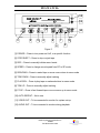
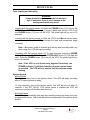
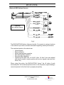
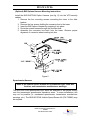
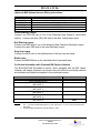
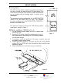
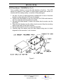
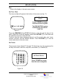
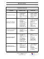
BUS-WATCH®
User Manual
Installation Manual
Radio Engineering Industries, Inc.
6534 L Street
Omaha, Nebraska 68117
402-339-2200
BUS-WATCH®
Table of Contents
INTRODUCTION
3
FEATURES
3
System Components
3
INITIAL SET UP
4
SYSTEM OVERVIEW
4
VCR Security Cabinet
BUS-WATCH® Camera
Reset Button
Tape Loading and Unloading
System Record
Automatic Heater Function
Automatic Shut Off
Service Reminder
5
5
7
7
7
8
8
8
SYSTEM INSTALLATION
9
System Wiring
(Optional) BW Options Harness
(Optional) BW Options Harness Mounting Instructions
Speedometer Harness
(Optional) BW Options Harness Wiring Instructions
Yellow Warning Lamps
Red Warning Lamps
Stop Arm Lamps
Brake Lamp
On-Screen Information with (Optional) BW Options Harness
Mounting Options
VCR Under Seat Mount
VCR Floor Mount
Mount Conversion
Slide Bracket Modification
VCR Cabinet Modification
Camera Placement
MENU SYSTEM
9
10
11
11
12
12
12
12
12
12
13
13
14
15
15
15
16
17
Menu Operation
Calibrate Speedometer
Set Options
Set Time / Date
Set Timers
System Info
17
18
19
21
21
22
SPECIFICATIONS
23
TROUBLESHOOTING GUIDE
24
2
Radio Engineering Industries, Inc.
640248
Rev B November 2001
BUS-WATCH®
INTRODUCTION
Thank you for purchasing the BUS-WATCH® surveillance system by Radio
Engineering Industries, Inc. This manual is intended to provide the user with
the information required for proper installation, initial setup and explanation
of the individual programming options. If you have any questions, or need
assistance, please call the:
SERVICE HOT LINE
1-877-726-4617 Toll Free USA & CANADA
SALES HOT LINE
1-800-228-9275 Toll Free USA & CANADA
1-402-339-2200
FEATURES
Ø
Ø
Ø
Ø
Ø
Ø
Ø
Ø
Ø
Ø
On screen menu system to program system options.
Video head cylinder heater prevents frost build up in cold weather.
Non-volatile memory with 10-year retention.
Automatic VCR power shut off.
Up to 16 character Route ID.
Ten - 24hr programmable timers set automatic record start and stop times
without user (driver) intervention.
Date, Time, and Route ID at the bottom of the picture so detail at the top of the
picture is not hidden.
Infra red light sources to enhance low light operation
Automatic Leap Year correction
Programmable options include:
o
o
o
o
Ø
Ø
Ø
Ø
Ø
Ø
Ø
Repeat record mode
0-35 minute record delay
Daylight savings time correction
12/24 hour clock format
Choice of user defined monitor points on vehicle.
Backward compatible with previous BUS-WATCH® models.
System information screen tracks system history.
On screen display reminds user to service VCR.
Audio and video out jacks located on the front of VCR for easy access.
Small volume CCD camera.
VCR cabinet may be mounted on floor or under seat.
System Components
Ø Industrial grade VCR mounted in metal security cabinet
Ø Slide Mount Bracket with Blind Mate Wiring Connectors
Ø Choice of CCD cameras - Low Light 700552 (8mm B&W), 700578 (8mm
Color), 700553 (decoy), 700555 (4mm B&W), 700554 (4mm B&W Conduit)
Ø Camera to VCR cable - 510781
Ø VCR cabinet power cable - 510880
Ø Mounting kits - 060094 and 060113
Ø (Optional) BW Options harness - 511617
Ø (Optional) Vehicle speed sensor kit- 750086
3
Radio Engineering Industries, Inc.
640248
Rev B November 2001
BUS-WATCH®
INITIAL SET UP
The BUS-WATCH® system may be installed and operate out of the box without
any user setup with the default settings, however, it may not show the correct date
and time. To set the correct date and time and program the system operation to
your requirements, please refer to the MENU section of this manual.
It is suggested the user purchase a small, portable video monitor to assist in the
system set up.
Installation Tips
•
•
•
•
•
Read the entire Instruction Manual before beginning the installation.
Connect the green “MEMORY” wire directly to the positive battery terminal.
Connect the black “GROUND” wire directly to the negative battery terminal or the vehicle
frame.
Provide extra care to avoid piercing the camera cable during installation – Refer to #9 in
the Troubleshooting Guide.
Completely check the system operation before dressing and hiding wires.
SYSTEM OVERVIEW
BUS-WATCH® is a superior surveillance system specifically designed for rugged
school bus applications. The system consists of an industrial grade VCR encased
in a tamperproof, lockable steel security cabinet and a surveillance camera of
sturdy steel housing. As an option, the BUS-WATCH® can monitor and record
vehicle functions such as warning lamp operation, brake, vehicle speed, and two
user defined points. Figure 1 shows each component and a typical hookup.
Figure 1
4
Radio Engineering Industries, Inc.
640248
Rev B November 2001
BUS-WATCH®
VCR Security Cabinet
The VCR security cabinet should be mounted horizontally on the floor or
under the seat with the VCR right side up. The VCR should not present a trip
hazard or head impact hazard and not interfere with the seating, safety, or
comfort of the passengers.
BUS-WATCH® Cameras
The cameras use solid-state image transducers to capture live action for the
VCR. The cameras employ an array of infra red light sources to enhance low
light operation. Cameras are available in a variety of configurations
including black & white, color, 8mm and 4mm.
Reset Button
If the VCR does not respond to user commands or does not operate
properly, a reset button is provided. The button is located near the rear
connector as shown in Figure 2.
Figure 2
5
Radio Engineering Industries, Inc.
640248
Rev B November 2001
BUS-WATCH®
AUDIO
OUT
VHS
VIDEO
OUT
12
11
MENU
STOP/EJECT
10
1
2
3
4
5
7
6
9
8
Figure 3
[1] POWER – Press to turn power on & off, or a specific function
[2] STOP/EJECT – Press to stop or eject tape
[3] REC – Press to manually initiate record mode
[4] SPEED – Press to change record speed from EP to SP mode
[5] REW/DWN – Press to rewind tape or move cursor down in menu mode
[6] TRK DOWN – Press to manually adjust tracking
[7] PLAY/SEL – Press to play tape or make selections in menu mode
[8] TRK UP – Press to manually adjust tracking
[9] FF/UP – Press to fast forward tape or move cursor up in menu mode
[10] AUTO REPEAT – Not in use
[11] VIDEO OUT – To be connected to monitor for system set-up
[12] AUDIO OUT – To be connected to monitor during playback
6
Radio Engineering Industries, Inc.
640248
Rev B November 2001
BUS-WATCH®
Tape Loading and Unloading
WARNING
If tape does not load when inserted, do not force
tape. If excessive force is used, damage to the
loading mechanism may occur.
Loading with the ignition switch off: Press the POWER button [1] to turn on the
VCR. With the POWER indicator lit [1] insert a blank tape into the VCR. Push
the POWER button [1] to turn off the VCR. The power light will go out in 10
seconds.
Loading with the ignition switch on: With the VCR in the Manual record mode,
insert the blank tape. The VCR will accept the tape and immediately begin
recording.
Note: if Automatic mode is selected and the day and time falls within any
timer range, the VCR will begin recording.
Unloading with the ignition switch off: To eject the tape, press the POWER
button [1] to turn on the VCR. Press the STOP/EJECT button [2]. The tape will
eject. Press the POWER button [1] to turn off the VCR. The power light will go
out in 10 seconds.
Note: If the VCR is cold (below forty degrees Fahrenheit), the
POWER indicator [1] will flash indicating that the internal heater
is activated. The VCR will not operate until the indicator stops
flashing.
System Record
Manual Mode
To begin recording, turn on the ignition switch. The VCR will begin recording
after a 10 second power up delay.
To stop recording, turn off the ignition switch. The VCR will shut off after 10
seconds. If the OFF DELAY 0-35 minute option is enabled the VCR will
continue to record until the delay has timed out.
Automatic Mode
The VCR will automatically start and stop recording during the times set by the
programmable timers. This mode will operate independent of the ignition switch
position.
7
Radio Engineering Industries, Inc.
640248
Rev B November 2001
BUS-WATCH®
Automatic Heater Function
To prevent the possibility of malfunction during cold periods, the VCR is
equipped with an automatic heater. The heater is activated for a predetermined
time when the VCR temperature falls below forty degrees Fahrenheit and the
user attempts to turn on the VCR or place it in record. During this time all VCR
functions are disabled. The POWER indicator light [1] will flash until the VCR is
able to operate.
Automatic Shut Off
The VCR will automatically shut off after 15 minutes of inactivity.
Service Reminder
A flashing clock symbol
in the upper right corner of the screen will appear
after 100 hours of record time. This indicates the VCR requires routine service.
The clock symbol may be reset by entering the SET OPTIONS menu, moving
the cursor to RESET SERVICE TIMER and press either the FF or REW button.
The SERVICE TIME display in the first SYSTEM INFORMATION screen will
also be reset to 000. Once reset, the on-screen reminder will reappear after
the next 100 hours of record time.
8
Radio Engineering Industries, Inc.
640248
Rev B November 2001
BUS-WATCH®
SYSTEM INSTALLATION
WARNING
REMOVE VEHICLE BATTERY VOLTAGE BEFORE INSTALLING
SYSTEM WIRING
System Wiring
Note: All cables should be hidden from view.
For the basic system (see fig. 4), there are two cables; power (510880) and
camera (510781). For additional vehicle monitoring, the BUS-WATCH® Options
harness (511617) is available.
Connect the camera to the VCR using cable P/N 510781. There is no specific
direction for this cable to be installed.
Connect power to the VCR using cable P/N 510880. The black wire connects to
the negative terminal of the battery. The green wire (labeled 12V MEM) connects
directly to the positive terminal of the battery. The green wire should be fused at
4 amps.
IF THE SYSTEM OPERATES IN THE MANUAL RECORD MODE, connect the
red wire (labeled 12V SW), to the switched side of the ignition switch. The red
wire should be fused at 2 amps. The red wire is disabled in the automatic
record mode.
*Connect GREEN wire DIRECTLY
to the positive terminal of the
battery.
*Connect BLACK wire DIRECTLY
to the negative terminal of the
battery.
Figure 4
Note: Green wire fused @ 4 Amps, Red wire fused @ 2 Amps
9
Radio Engineering Industries, Inc.
640248
Rev B November 2001
BUS-WATCH®
(Optional) BW Options Harness
FROM
FLASHER
FROM
FLASHER
FROM
FLASHER
FROM
FLASHER
(Optional)
BW Options Harness
FROM
FLASHER
FROM BRAKE
PEDAL SWITCH
Fig.5
The BUS-WATCH® Options Harness (see fig. 5) connects to various locations
in the vehicle to provide on-screen information regarding vehicle performance.
The monitored points in the vehicle are:
• Vehicle speed
• Brake activation
• Amber warning lamp operation
• Red warning lamp operation
• Stop arm lamp operation
• Optional points with AUX 1 & AUX 2 (Aux 1 & Aux 2 are user defined
and may be used to monitor points such as turn signals, rear and front
doors, etc.)
When using this option, the BUS-WATCH® “learns” the off state of each
monitored point. All monitored points must be in the off position upon initiating a
record sequence for the first time to properly set polarity.
10
Radio Engineering Industries, Inc.
640248
Rev B November 2001
BUS-WATCH®
(Optional) BW Options Harness Mounting Instructions
Install the BUS-WATCH® Option Harness (see fig. 6) into the VCR security
cabinet.
1. Remove the four mounting screws connecting the tower to the slide
bracket.
2. Remove the four screws holding the connector box to the tower.
3. Insert the BW Options Harness by snapping it into place.
4. Route the excess harness through the provided hole
5. Assemble the connector box back onto the tower. Observe proper
alignment of connector when inserting into box.
Figure 6
Speedometer Harness
Refer to the vehicle service manual for speedometer type, exact wire
location, and transmission manufacturer warnings.
The BUS-WATCH® speedometer input wires are designed to be spliced directly
onto the transmission speedometer transducer wires. In some installations, this
may not be possible (i.e. mechanical speedometer, transmission manufacturer
warnings, etc.). The BUS-WATCH® Vehicle Speed Sensor Kit (P/N 750086) may
be required.
11
Radio Engineering Industries, Inc.
640248
Rev B November 2001
BUS-WATCH®
(Optional) BW Options Harness Wiring Instructions
WIRE COLOR
(2) YELLOW
(2) RED
BLUE
BROWN
WHITE
VIOLET
WIRE DESCRIPTION
RIGHT & LEFT YELLOW WARNING LAMP BANK
RIGHT & LEFT RED WARNING LAMP BANK
STOP ARM LAMP
BRAKE PEDAL LAMP
AUX SIGNAL 1
AUX SIGNAL 2
Yellow Warning Lamps
Connect one YELLOW wire to one of the Warning Lamp Flasher’s Yellow lamp
outputs. Connect the other YELLOW wire to the other Yellow lamp output.
Red Warning Lamps
Connect one RED wire to one of the Warning Lamp Flasher’s Red lamp outputs.
Connect the other RED wire to the other Red lamp output.
Stop Arm Lamps
Connect the BLUE wire to the switched side of the top stop arm lamp.
Brake Lamp
Connect the BROWN wire to the switched side of one brake lamp.
On-Screen Information with (Optional) BW Options Harness
The BUS-WATCH® Surveillance system, when equipped with the BW Option
Harness, will display information on-screen when the vehicle’s monitored switches
are activated and signals are applied to the monitored sensors.
ACTIVE SWITCH OR SIGNAL
BRAKE APPLIED
STOP ARM DEPLOYED
LEFT YELLOW WARNING LAMPS ON
(SEE NOTE 1)
RIGHT YELLOW WARNING LAMPS ON
(SEE NOTE 1)
LEFT RED WARNING LAMPS ON
(SEE NOTE 1)
RIGHT RED WARNING LAMPS ON
(SEE NOTE 1)
SPEEDOMETER
(SEE NOTE 2)
ON-SCREEN DISPLAY
B
S
*Y
Y*
*R
R*
XXX
MPH
NOTES:
1.
2.
The “*” symbols will alternately appear on each side of the “Y” or “R” in concert with the active
lamp bank.
The three XXXs represent the vehicle speed (i.e. 035).
12
Radio Engineering Industries, Inc.
640248
Rev B November 2001
BUS-WATCH®
Mounting Options
The VCR security cabinet should be mounted horizontally on
the floor or under the seat with the VCR right side up. The
VCR should not present a trip hazard or head impact hazard
and not interfere with the seating, safety, or comfort of the
passengers.
The standard mounting configuration for the BUS-WATCH®
700636 is to the under side of a seat. The standard
mounting configuration for the BUS-WATCH® 700636FM is
directly to the vehicle floor.
The minimum clearance area for the VCR security cabinet
installation is shown in Figure 7.
VCR Under seat Mount – 700636 (see Fig. 8)
1. Find a suitable location under the first or second seat
behind the driver.
Figure 7
2. An area 15-1/2 inches should be unobstructed in front of
the slide bracket to allow sliding the VCR security cabinet
onto the slide bracket.
3. If necessary, modify the positions of the tower, connector box, and
slide rails to match picture below.
4. Position the slide bracket on the frame of the seat in the desired
location. Drill four 5/16th inch holes through the frame using the slide
bracket as a guide.
5. Attach slide bracket to seat frame using nuts and bolts.
Figure 8
13
Radio Engineering Industries, Inc.
640248
Rev B November 2001
BUS-WATCH®
VCR Floor Mount – 700636FM (See Fig. 9)
Find a suitable location to mount the slide bracket on the floor. The VCR
should not present a trip hazard or head impact hazard and should not
interfere with the seating, safety, or comfort of the passengers.
1. An area 15 and 1/2 inches should be unobstructed in front of the slide
bracket to allow sliding the VCR onto the bracket.
2. Position the slide bracket on the floor and drill four 3/16th inch holes into
the floor using the mounting holes as a guide.
3. Set aside the slide bracket. Position four rubber shock mounts over the
pilot holes.
4. Place the slide bracket over the rubber shock mounts. Align the mounting
holes to the center of the shock mounts.
5. Secure slide bracket to the floor using four lag bolts.
6. Carefully slide the cabinet onto the slide bracket being sure to check
alignment of the connector. Lock to secure.
Figure 9
14
Radio Engineering Industries, Inc.
640248
Rev B November 2001
BUS-WATCH®
Mount Conversion
Either BUS-WATCH® models, 700636 or 700636FM, may be converted to mount
in the other method. The slide bracket and the VCR security cabinet must be
modified.
Slide Bracket Modification (see Fig. 10)
1. Remove tower from slide bracket using four cap screws [1].
2. Slide tower to other side of bracket.
3. Reattach tower to slide bracket using four cap screws [1].
4. Remove connector box from tower using four screws [2].
5. Rotate connector box such that the rubber grommet
is on the outside edge of the tower.
6. Reattach connector box to tower using four screws [2].
2
2
1
1
Figure 10
VCR Cabinet Modification (see Fig. 11)
Reverse the placement of the slide rails with screws and washers [1] from
top to bottom of VCR.
1
Figure 11
15
Radio Engineering Industries, Inc.
640248
Rev B November 2001
BUS-WATCH®
Camera Placement
Mount the BUS-WATCH® camera securely in the center of the front header panel
or ceiling panel. Stable support is essential to avoid excessive vibration. Connect
a monitor (User supplied - optional monitor available from REI - P/N 690193) to
the VCR using the front jacks labeled AUDIO OUT [12] and VIDEO OUT [11] to
set the camera angle and test the audio (see Fig. 12).
Figure 12
16
Radio Engineering Industries, Inc.
640248
Rev B November 2001
BUS-WATCH®
MENU SYSTEM
The menu allows the user to program the system operating parameters. Connect
a monitor to the VCR using the front jacks labeled AUDIO OUT [12] and VIDEO
OUT [11] to view the menu screens. The end user supplies the monitor and cable
for connection to the VCR. Optional monitor available from REI, P/N 690193.
Controls
There are three dual function buttons controlling the menu system. (see fig 13)
• REW/DWN [5] - this button moves the cursor down or decreases the
alpha/numeric value during programming.
• FF/UP [9] - this button moves the cursor up or increases the
alpha/numeric value during programming.
• PLAY/SEL [7] – use this button to select the menu item to be
changed. This button acts as the “enter” key.
MENU
Figure13
Menu Operation
To activate the menu system, press the POWER button [1] to turn on the VCR.
Insert high quality VHS video tape. Press and hold the REW/DWN [5] and FF/UP
[9] buttons at the same time until the menu screen appears. The first screen is the
main menu (see fig.14). The cursor should be flashing on the CALIBRATE
SPEEDOMETER line. To select which function to program, press REW/DWN [5]
until the cursor is flashing on the desired line. Press PLAY/SEL [7] to select the
screen.
Main Menu
Screen
Figure 14
17
Radio Engineering Industries, Inc.
640248
Rev B November 2001
BUS-WATCH®
The CALIBRATE SPEEDOMETER screen is used to program the system speed
display on the VCR to match the actual speed of the vehicle.
The SET OPTIONS screen is used to program the OFF DELAY, REPEAT
RECORD, DAYLIGHT SAVING TIME, etc. by the user.
The SET TIME/DATE screen is used to program the correct time and date.
The SET TIMERS screen is used to program the start and stop record times for
the ten programmable timers.
The SYSTEM INFO screen displays the current software information, system
record time, hi/low voltages and hi/low enclosure temperatures. This screen may
not be viewed when the bus ignition switch is on or if the VCR is recording.
EXIT returns the VCR to live camera video.
Calibrate Speedometer
(Requires two individuals – driver and programmer)
The CALIBRATE SPEEDOMETER screen (see fig. 15) is used to program the
system speed display to match the actual speed of the vehicle. With the vehicle in
motion, press the FF/UP [9] or REW/DWN [5] buttons to adjust the speed
displayed.
In order to start the calibration process over, press the POWER button [1] n
order to restore the factory calibration settings.
Calibrate Speedometer
Screen
Figure 15
18
Radio Engineering Industries, Inc.
640248
Rev B November 2001
BUS-WATCH®
Set Options
The SET OPTIONS screen (see fig.16) allows the user to program the system to
specific individual requirements or return to the factory default settings. Press the
FF/UP [9] or REW/DWN buttons [5] to change the item. Press the PLAY/SEL [7]
to save the change and go to the next item. Exiting this screen will return to the
main menu screen
.
Screen Set
Options
Press “POWER to escape
from this menu at anytime
Figure 16
Factory Default
When set to Yes, the unit will default to the following factory presets: Off Delay
changes to 00, Repeat Record changes to Yes, Record Mode changes to M,
Daylight Saving Time changes to Yes, 24 Hour Mode changes to No, the
Display Level changes to 6, and the menu drops to Route ID.
When set to No, the user may change any option to individual preferences.
Record Mode
When set to Automatic, record times are set by the enabled programmable
timers only. The ignition switch will NOT place the unit into record when the
Automatic Mode is set.
When set to Manual, recording is controlled from the ignition switch.
Off Delay 0-35 min
When set to 00 the VCR will stop recording immediately after the ignition switch
is turned off.
When set from 1-35, the VCR will continue to record for the selected time after
the ignition switch is turned off.
Note: Off Delay is disabled when in Automatic mode
19
Radio Engineering Industries, Inc.
640248
Rev B November 2001
BUS-WATCH®
Repeat Record
When set to Yes, the VCR will automatically rewind the tape and record over
the previous material when the end of the tape is reached.
When set to No, VCR will stop recording at the end of the tape. Tape does not
rewind. When the end of the tape is reached, there is no indication to the
driver that the VCR is not recording.
**AUTO REPEAT button [10] is disabled from the front of the VCR and can
only be accessed through the above menu.
Daylight Save Time
When set to Yes the VCR clock will automatically adjust for daylight saving
time. Power must be applied to the memory (green) wire for the system to
update.
When set to No, then the clock will not update.
24 Hour Mode
When set to Yes the clock will be displayed in a 24hr format.
When set to No the clock will be displayed in a 12hr format. All timers and
clocks are set in the 12hr format.
Display Level
The display level allows the user to select the information that is displayed over
the live camera video. The settings are:
0 - Display nothing
1 - Display time only
2 - Display calendar only
3 - Display time and calendar only
4 - Display route ID only
5 - Display route ID and time only
6 - Display route ID, time, and calendar only
7 - Display time, calendar, and switch between route ID, and temp & voltage
8 - Display time, calendar, temp & voltage
Route ID
The characters may be set by pressing the REW/DWN [5] or FF/UP [9] buttons
to step through the characters. When the desired character appears, press the
PLAY/SEL [7] button to enter and save the selected character and move to the
next character position.
Reset Service Timer
When 100 hours of recording time has elapsed, a flashing clock symbol
will
appear in the upper right corner of the display. A flashing “Y” will also be
displayed on the RESET SERVICE TIMER line. Press the REW/DWN [5] or
FF/UP [9] buttons to reset the service timer and turn off the “Y”.
Note: Be sure to service the VCR regularly.
20
Radio Engineering Industries, Inc.
640248
Rev B November 2001
BUS-WATCH®
Exit
Returns the display to the main menu screen.
Set Time / Date
The time and date will appear at the bottom of the screen (see fig. 17).
Set Time/Date
Screen
Press “POWER to escape
from this menu at anytime
The BUS-WATCH® system
automatically corrects for
Leap Year
Figure 17
Press the REW/DWN [5] or FF/UP [9] buttons to step through the days of the
week. When the correct day appears, press the PLAY/SEL [7] to enter and save
the selection and move to the next item.
Continue using the same buttons as above to set the month, date, year, hours,
minutes, seconds, and the AM/PM indicator. Press PLAY/SEL [7] to exit the
screen and return to the main menu.
Set Timers
There are ten timers labeled T0 through T9. Each timer may be programmed for
the day of the week, start time, stop time, and enable (Y) or disable (N).
Set Timers Screen
Press “POWER to escape
from this menu at anytime
Figure 18
21
Radio Engineering Industries, Inc.
640248
Rev B November 2001
BUS-WATCH®
Use the FF/UP [9] and REW/DWN [5] buttons to move the cursor to select the
timer. Press the PLAY/SEL [7] to select the timer and move to set the day of the
week.
Use the FF/UP [9] or REW/DWN [5] buttons to change the day of the week. When
the desired day is displayed, press the PLAY/SEL [7] to enter and save the data
and move to the start time.
Press the FF/UP [9] or REW/DWN [5] buttons to change the hour. When the
desired hour is reached press the PLAY/SEL [7] to enter and save the change
and go to the next field. Continue setting the start minutes, start am/pm, stop
hour, stop minute, stop am/pm, and the enable flag (Y/N) and return to the timer
number. Press the FF/UP [9] or REW/DWN [5] button to move to the next timer or
EXIT. Press PLAY/SEL [7] to select the next timer or exit.
Note: All timers should be set prior to recording.
Note: If the start time is set equal to the stop time the timer will not start
System Information
There are two system information screens. (see figs. 19 &20). The first screen
shows the SOFTWARE VERSION number, SPEEDOMETER CALIBRATION
factors, TOTAL RECORD TIME in hours, and the SERVICE TIMER. Press the
REW/DWN [5] button to display the next screen or the PLAY/SEL button [7] to
exit.
The second screen displays the minimum and maximum voltages and enclosure
temperature readings taken when the BUS-WATCH® is recording. The
temperature and voltage data may be reset by pressing the POWER button [1].
Press the REW/DWN [5] button to display the previous screen or the PLAY/SEL
button [7] to exit.
Figure 19
Figure 20
22
Radio Engineering Industries, Inc.
640248
Rev B November 2001
BUS-WATCH®
SPECIFICATIONS
VCR Security Cabinet
Size (with slide bracket)
Height
Width
Depth
Weight (without bracket)
Power Consumption
Standby
Recording
Heater
6 inches maximum
11-1/4 inches maximum
15-1/2 inches maximum
25 pounds
36 mA
1100 mA
1900 mA
Slide Bracket
Height
Width
Depth
Weight
1.23 inches
9.76 inches
13.34 inches
4 LB 14 oz
Camera
Image device
Focal length
Angle of view (D x H x V)
Luminance Sensitivity
Electronic Iris
Power Supply
Power consumption
Height
Width
Depth
Weight (with bracket)
1/3 inch
8 mm, 4mm
40.1’ x 32.6’ x 24.7’
0.1 Lux
1/100,000 sec
12V
145 mA
3 inches
3 inches
3 inches
20.7 ounces
VCR Specifications
Format
FF/REW Time
Video Output
Audio Output
Operating Temperature
VHS NTSC Standard
Less than 7 minutes with T120 tape
1Vp-p, 75 Ohm unbalanced
-5dBm, 600 Ohm unbalanced
-30° F to 150° F
Maximum switch/sensor input voltage
15 VDC (any input)
Speedometer
Electronic
2 - 15 Volt Pulse
30 - 70% Duty cycle
Design criteria - 16 pulses/revolution
Mechanical
Design criteria - 1000 revolutions/mile
23
Radio Engineering Industries, Inc.
640248
Rev B November 2001
BUS-WATCH®
TROUBLESHOOTING GUIDE
PROBLEM
POSSIBLE CAUSE
CORRECTION
1
VCR DOES NOT TURN ON
2
•
•
•
NO VCR POWER
NO GROUND
INSERT HIGH
QUALITY VHS VIDEO
TAPE
•
•
NO VOLTAGE ON
RED WIRE
VCR DOES NOT
TURN ON
VCR IN AUTOMATIC
RECORD MODE
NO TAPE IN VCR
RECORD TAB
BROKEN ON TAPE
•
VCR DOES NOT
TURN ON
MICROCONTROLLER
PROGRAM
•
•
SEE #1
PRESS RESET
SWITCH
VCR DOES NOT
TURN ON
TIMER ENABLE SET
TO “N”
VCR IN MANUAL
RECORD MODE
NO TAPE IN VCR
RECORD TAB
BROKEN ON TAPE
•
•
SEE #1
SET TIMER ENABLE
TO “Y”
SET VCR TO
AUTOMATIC
RECORD MODE
INSERT TAPE
REPLACE TAPE
CHECK
INSTALLATION OF
CONNECTOR
CHECK ELECTRICAL
CONNECTIONS
•
•
VCR WILL NOT RECORD
WHEN BUS IS RUNNING
•
•
•
•
•
•
•
•
CONNECT GREEN
WIRE TO +BATTERY
CONNECT BLACK
WIRE TO VEHICLE
GROUND
CONNECT RED WIRE
TO SWITCHED SIDE
OF IGNITION
SEE #1
SET VCR TO
MANUAL RECORD
MODE
INSERT TAPE
REPLACE TAPE
3
•
VCR DOES NOT RESPOND
TO USER COMMANDS
•
4
•
•
VCR DOES NOT RECORD
WHEN PROGRAMMED
•
•
•
5
ON SCREEN VEHICLE
OPTIONS DO NOT DISPLAY
•
•
24
Radio Engineering Industries, Inc.
640248
Rev B November 2001
•
•
•
•
TURN CONNECTOR
OVER IN POWER
BOX
MEASURE
ACTUATION
VOLTAGE – REPAIR
AS NEEDED
BUS-WATCH®
TROUBLESHOOTING GUIDE
PROBLEM
POSSIBLE CAUSE
CORRECTION
6
•
BUS-WATCH®
SPEEDO CIRCUITRY
LOADING THE
VEHICLE
COMPUTER SYSTEM
•
INSTALL BUSWATCH®
SPEEDOMETER
ATTENUATOR
•
NOISE INDUCED ON
THE SPEEDO
PICKUP WIRE
•
INSTALL BUSWATCH®
SPEEDOMETER
ATTENUATOR
•
MEMORY WIRE
(GREEN) VOLTAGE
FALLS BELOW 9V
•
CHECK VOLTAGE AT
GREEN WIRE
CONNECTION POINT
WHILE THE VEHICLE
IS IDLING
GREEN WIRE NOT
CONNECTED
DIRECTLY TO
+BATTERY
VEHICLE SPEEDOMETER
QUITS WHEN BUS-WATCH®
SPEEDO CIRCUITRY
APPLIED
7
BUS-WATCH® SPEEDO
DISPLAY READS 3-10MPH
WHEN VEHICLE IS IDLING
8
VCR STOPS RECORDING
WHEN VEHICLE COMES TO
A STOP OR IS IDLING
•
9
•
CAMERA CABLE HAS
BEEN PIERCED
CREATING A
GROUND LOOP
•
REPAIR CAMERA
CABLE
INSTALLATION
•
VCR DOES NOT
TURN ON
NO POWER APPLIED
TO CAMERA
•
•
SEE #1
CHECK CAMERA
CABLE
CONNECTIONS
CAMERA IRIS IS
CLOSED
CAMERA IS OUT OF
FOCUS
•
•
RESET CAMERA IRIS
REFOCUS CAMERA
DIRTY VCR RECORD
HEADS
•
SERVICE VCR
RECORDED AUDIO HAS
HUM OR ALTERNATOR
NOISE
10
NO VIDEO
•
11
•
NO VIDEO – ONLY ON
SCREEN INFORMATION
12
POOR PICTURE OR AUDIO
QUALITY ON PLAYBACK
•
•
25
Radio Engineering Industries, Inc.
640248
Rev B November 2001
BUS-WATCH®
26
Radio Engineering Industries, Inc.
640248
Rev B November 2001


![SOLOSTORM USER GUIDE [VERSION 1.2]](http://vs1.manualzilla.com/store/data/005689152_1-d7af094c3c32ee16b7966cd6221b7607-150x150.png)