1
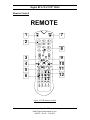
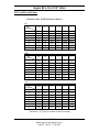
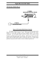
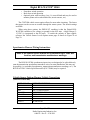
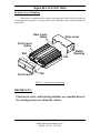
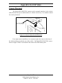
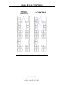
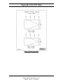
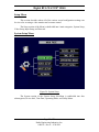
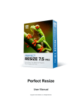
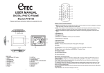
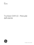
Digital BUS-WATCH®
Digital
®
BUS-WATCH
SD40
710292
Hardware User Manual
Hardware Installation Manual
Page 1 of 72
Radio Engineering Industries, Inc.
640434 -- Rev 0 -- 9/30/2011
Digital BUS-WATCH® SD40
Table of Contents
Table of Contents .............................................................................................................. 2
List of Figures .................................................................................................................... 4
Introduction ....................................................................................................................... 6
System Overview ............................................................................................................ 8
Front and Back Panels .................................................................................................... 9
Remote Control ............................................................................................................. 11
Initial Set Up ................................................................................................................. 14
Removable SD Card ..................................................................................................... 14
DVR Loading and Unloading ............................................................................................... 14
SD Card Record Times ......................................................................................................... 16
Long Term Storage ............................................................................................................... 17
Installation ....................................................................................................................... 18
System Wiring – Power and Camera Cables ................................................................ 18
External Record Indicator / Event Mark Button Harness ............................................. 20
GPS Antenna Module Harness ..................................................................................... 21
Vehicle Sensor Options Harness ................................................................................... 22
Speedometer Harness Wiring Instructions ........................................................................... 23
Vehicle Sensor Options Harness Vehicle Connections ........................................................ 23
On-Screen Information with Vehicle Sensor Options Harness ............................................ 24
Accelerometer Module Harness................................................................................. 25
Physical Mounting Requirements ............................................................................. 26
Page 2 of 72
Radio Engineering Industries, Inc.
640434 -- Rev 0 -- 9/30/2011
Digital BUS-WATCH® SD40
L Bracket Mounting.............................................................................................................. 26
Security Cover Mounting ..................................................................................................... 27
Camera Placement ........................................................................................................ 28
Typical Camera Lens Viewing Angles ................................................................................. 31
Recording & Playback .................................................................................................... 33
System Start-Up ............................................................................................................ 33
System Shut-Down ....................................................................................................... 33
Playback Options .......................................................................................................... 34
Menu Configuration ....................................................................................................... 35
Installers Mode Page ..................................................................................................... 35
Main Menu Page ........................................................................................................... 36
Setup Menu ........................................................................................................................... 37
System Setup Menu .............................................................................................. 37
Video Setup ........................................................................................................... 46
Input Setup ............................................................................................................ 52
Network................................................................................................................. 60
Play Back .............................................................................................................................. 64
Video Search ......................................................................................................... 65
DVR Firmware Upgrading ............................................................................................ 71
Front Panel USB Firmware Upgrade ............................................................................ 71
Ethernet Firmware Upgrade .......................................................................................... 71
Specifications ................................................................................................................... 72
Page 3 of 72
Radio Engineering Industries, Inc.
640434 -- Rev 0 -- 9/30/2011
Digital BUS-WATCH® SD40
List of Figures
Figure 1: SD40 Expanded System Overview ..................................................................... 8
Figure 2: Front Panel Layout .............................................................................................. 9
Figure 3: Rear Panel Layout ............................................................................................. 10
Figure 4: DVR Remote Control ........................................................................................ 11
Figure 5: Remote Control Button Description .................................................................. 12
Figure 6: Remote Control Navigation Arrows.................................................................. 12
Figure 7: Remote Control Numeric Input Keys ................................................................ 13
Figure 8: Removable Hard Drive Module Loading and Unloading ................................. 15
Figure 9: System Wiring – Power and Camera Cables..................................................... 19
Figure 10: External Record Indicator / Event Mark Button Harness Connection ............ 20
Figure 11: GPS Antenna Module Harness Connection .................................................... 21
Figure 12: Vehicle Sensor Options Harness Connection .................................................. 22
Figure 13: Accelerometer Module Harness Connection ................................................... 25
Figure 14: 3 Axis Inertia Sensor Directions ..................................................................... 25
Figure 15: L Bracket Mounting ........................................................................................ 26
Figure 16: DVR Dimensions ............................................................................................ 26
Figure 17: Security Cover Mounting ................................................................................ 27
Figure 18: Camera Connection and Placement ................................................................. 28
Figure 19: Potential Single and Two Camera Placement Options .................................... 29
Figure 20: Potential Multiple Camera Placement Options ............................................... 30
Figure 21: 4mm Lens Angles ............................................................................................ 31
Figure 22: 8mm Lens Angles ............................................................................................ 32
Figure 23: Connecting to the DVR with a Computer through the Ethernet Connection .. 34
Figure 24: Installers Mode ................................................................................................ 35
Figure 25: Main Menu ...................................................................................................... 36
Figure 26: System Setup ................................................................................................... 37
Figure 27: Device Info ...................................................................................................... 38
Figure 28: Device History ................................................................................................. 39
Figure 29: System – Time/Date ........................................................................................ 40
Figure 30: Custom DST Triggers ..................................................................................... 41
Figure 31: Operating Mode ............................................................................................... 42
Figure 32: Schedule Menu ................................................................................................ 43
Figure 33: System – Utility Menu .................................................................................... 44
Figure 34: System – Password Protection ........................................................................ 45
Figure 35: Video Setup ..................................................................................................... 46
Figure 36: Camera – Record Settings ............................................................................... 47
Figure 37: Custom Record Settings .................................................................................. 48
Figure 38: Sub-streaming .................................................................................................. 49
Figure 39: System – Live Video Settings ......................................................................... 50
Figure 40: OSD Settings ................................................................................................... 51
Figure 41: Input Setup ...................................................................................................... 52
Figure 42: Sensor Input ..................................................................................................... 53
Figure 43: Auto-download Settings .................................................................................. 54
Page 4 of 72
Radio Engineering Industries, Inc.
640434 -- Rev 0 -- 9/30/2011
Digital BUS-WATCH® SD40
Figure 44: Accelerometer Threshold ................................................................................ 55
Figure 45: Temperature Threshold ................................................................................... 56
Figure 46: Speed Threshold .............................................................................................. 57
Figure 47: Alarm Settings ................................................................................................. 58
Figure 48: Audible Settings .............................................................................................. 59
Figure 49: Network ........................................................................................................... 60
Figure 50: Ethernet Settings.............................................................................................. 61
Figure 51: Wi-Fi Settings.................................................................................................. 62
Figure 52: 3G Network Settings ....................................................................................... 64
Figure 53: Play Back Function ......................................................................................... 64
Figure 54: Video Search Page........................................................................................... 65
Figure 55: Files List Page ................................................................................................. 66
Figure 56: Files List Page Extra Function ........................................................................ 67
Figure 57: Event Search Function..................................................................................... 68
Figure 58: Event List Page ................................................................................................ 69
Figure 59: Event List Page Extra ...................................................................................... 70
Page 5 of 72
Radio Engineering Industries, Inc.
640434 -- Rev 0 -- 9/30/2011
Digital BUS-WATCH® SD40
Introduction
All of us at Radio Engineering Industries, Inc. would like to thank you for
purchasing a Digital BUS-WATCH® surveillance system. This manual is intended to
provide the user with the information required for proper installation, initial setup and
explanation of the individual programming options. If you have any questions, or need
assistance, please call:
SERVICE HOT LINE
USA & CANADA
1-877-726-4617 Toll Free
1-402-339-2200
The SD40 is a cost effective, fanless, embedded mobile DVR solution supporting
up to 4 camera inputs. This system features a unique compact rugged design engineered
to meet the demands of harsh mobile environments. The SD40 mobile DVR features the
latest technologies including H.264/MPEG-4 Advanced Video Compression, dual
streaming technology, and all solid state construction.
Features
● Ultra compact extruded aluminum housing, low weight, high temperature
and vibration resistant
● Low-voltage, low-current architecture designed for harsh mobile environments
● Removable SD Cards with tamper-resistant lock and secure controls
● All DVRs fully support NTSC and PAL, Fahrenheit and Celsius, KM/H and
MPH
● Communications are supported through a TCP / IP network interface and a
USB connection to PCs
● Each DVR comes with a hand-held IR remote control with on-screen display
(OSD) for configuration and control of the DVR
● 4 channels for video input, full-motion (30 FPS / camera) continuous video
recording and display. 4 channels for high-fidelity, digitally recorded, 4
independent synchronized audio channels matched to 4 independent video
channels
● Secure, constant recording while system is powered with event bookmarks for
easy event searching
● Utilizes H.264/MPEG-4 Advanced Video Compression for high video quality,
low storage requirements, and long record times
● User-selectable settings for quality and audio record enable / disable for each
video channel
● Multi-level password protection for settings, playback, remote access, and more
Page 6 of 72
Radio Engineering Industries, Inc.
640434 -- Rev 0 -- 9/30/2011
Digital BUS-WATCH® SD40
● Integrated and filtered power supply for cameras, sensors, relays and other
accessories
● Selectable idle frame rate with event-triggered burst recording speeds up to
30fps / camera
● Multiple alarm inputs with selectable pre-alarm and post-alarm recording
● Full event logging of every operation controlled by the DVR
● TV output channel for recorded and live videos
Video Viewing
● DVD-quality steaming audio / video channel with independent NTSC or PAL
television output
● Convenient SD card, USB, or TCP / IP media updating and status file
downloading
● Award winning Live View and Play Back PC Software
Video Retrieval and Archiving
● Ethernet port on the rear panel for easy video retrieval on the vehicle with a
notebook computer
● Two sets of video and audio outputs for monitor viewing on the vehicle
● USB 2.0 connection for fast file transfer utilizing USB flash drives
● Easy to use PC-based software application for playback, file transfer, archiving
management, and video file format conversion
● Vehicle management PC software interprets audio, video, and vehicle data for
driver and vehicle use assessment
● Video event search software allows intelligent searching of video based on
event information
Supplemental Data and Driver Management Modules
● External GPS antenna module for embedded digital information of GPS
location, speed, heading, and time
● External 3-axis inertia sensor for embedded digital information or trigger of
video-matched motion events for accident reconstruction
Page 7 of 72
Radio Engineering Industries, Inc.
640434 -- Rev 0 -- 9/30/2011
Digital BUS-WATCH® SD40
System Overview
DIGITAL BUS-WATCH System Diagram
R
CAMERAS
INDOOR WEDGE
SD40 MOBILE DVR SYSTEMS
OR
DOME
(VARIOUS LENGTHS AVAILABLE)
**ADD CAMERA SWITCH DEVICE (710030)
IF MORE CAMERA INPUTS NEEDED
VEHICLE SENSOR HARNESS (OPT)
512209 - 20 FT.
512208- 50 FT.
OR
OUTDOOR WEDGE
CAM CAM CAM CAM
1
3
4
2
ALARM/PANIC CABLE
OEM 512024 - 20 FT.
512025 - 40 FT.
511986 - 20 FT. TRIGGER
AFTERMARKET
512023 - 40 FT.
710292
BUS-WATCH DVR, SD40
SENSORS
TRIGGER
SENSORS
CAM 1
CAM 2
750243
FRONT CAP KIT
(OPT)
CAM 3
CAM 4
ETHERNET
BUS-WATCH
REAR
VIEW
OR
HR-SERIES
USB 2.0
R
UNLOCK
SD
POWER
12V OUT
GPS
AUDIO
OUT
HTR REC VID SD
LOSS FULL
Use REI Approved SD Card Only
ACC
VIDEO
OUT
PWR SD ALM FAULT
2.4 GHz
ANTENNA
210121
(COMES w/832101)
ETHERNET CABLE
3 FT.
530068
ETHERNET CABLE (OPT)
512359
SD40 DVR
POWER CABLE
16-1/2 FT.
VARIOUS LENS
SIZES AVAILABLE
530073
17 FT.
ANTENNA CABLE
VIDEO
POWER GPS ACC
GPS RECEIVER
710214
710143
ACCELEROMETER MODULE
NETWORK
CABLE 3 FT.
530068
DVR
512378
POWER
802.11G
WIRELESS BRIDGE
710163
750252 SD40 BRIDGE KIT
IGN
12V SW
GROUND
USB
FLASH
DRIVE
(OPT)
832101
MB1
CELL
832200
ANT
1
710277
COMPUTER
(OPT)
REI APPROVED SD CARDS
SD CARDS
16 GB - 690632
32 GB - 690633
FRONT
VIEW
REMOTE
AUDIO CABLE
(OPT)
530018
CABLE 3FT.
110468
ADAPTOR
AUD
IN
690565
4.5 INCH
750207 COLOR PROTABLE
VIDEO MONITOR MONITOR
KIT (OPT)
POWER CABLE
(COMES w/832101)
Figure 1: SD40 Expanded System Overview
Page 8 of 72
Radio Engineering Industries, Inc.
640434 -- Rev 0 -- 9/30/2011
750244
REAR CAP KIT
(OPT)
AUDIO
*CAMERA CABLES
Digital BUS-WATCH® SD40
Front and Back Panels
FRONT PANEL LAYOUT
7
BUS-WATCH
6 5
R
UNLOCK
SD
USB 2.0
VIDEO
OUT
AUDIO
OUT
PWR SD ALM FAULT
Use REI Approved SD Card Only
1
HTR REC VID SD
LOSS FULL
2 3 4
1 SD CARD SLOT (DOOR CLOSED)
2 USB 2.0 CABLE CONNECTION
3 LED STATUS INDICATORS, (8 INDICATORS)
4 REMOTE I.R. SENSOR
5 AUDIO OUTPUT CONNECTOR
6 VIDEO OUTPUT CONNECTOR
7 SD CARD DOOR LOCK
Figure 2: Front Panel Layout
Page 9 of 72
Radio Engineering Industries, Inc.
640434 -- Rev 0 -- 9/30/2011
Digital BUS-WATCH® SD40
REAR PANEL LAYOUT
17 16
SENSORS
TRIGGER
POWER
8
15
CAM 1
12V OUT
CAM 2
GPS
CAM 3
14
CAM 4
ETHERNET
ACC
9 10 11 12 13
8 POWER CABLE CONNECTION
9 ACCESSORY POWER
10 GPS (GPS RECEIVER CONNECTION)
11 ACC (ACCELEROMETER MODULE CONNECTION)
12 AUDIO OUTPUT CONNECTION
13 VIDEO OUTPUT CONNECTION
14 ETHERNET CABLE CONNECTION
15 CAMERA INPUTS (CAM 1-4 )
16 SENSORS (VEHICLE SENSOR CABLE CONNECTION)
17 TRIGGER (ALARM/PANIC CABLE CONNECTION)
Figure 3: Rear Panel Layout
Page 10 of 72
Radio Engineering Industries, Inc.
640434 -- Rev 0 -- 9/30/2011
Digital BUS-WATCH® SD40
Remote Control
REMOTE
7
1
2
8
3
4
5
6
9
10
11
12
Figure 4: DVR Remote Control
Page 11 of 72
Radio Engineering Industries, Inc.
640434 -- Rev 0 -- 9/30/2011
Digital BUS-WATCH® SD40
I.D.
1
2
3
LABEL
FUNCTION
POWER
Turn DVR On/Off
Numeric
"1" through "4" Select Camera
NEXT
Volume UP
4
REW
Playback Function, X2, X4
5
PREV
Volume DOWN
6
7
Playback Functions
LOGIN/LOCK
Access Menu
8
"0"
9
ENTER
10
FWD
11
SETUP
Menu
12
EXIT
Exit
Quad Screen
Installers Mode
Playback Function, X2, X4
Figure 5: Remote Control Button Description
NAVAGATION ARROWS
Use the ARROW keys to
move between selections,
input fields and icons. Press
ENTER to select and EXIT to
return. NEXT and PREV is
also used to increase or
decrease volume.
Figure 6: Remote Control Navigation Arrows
Page 12 of 72
Radio Engineering Industries, Inc.
640434 -- Rev 0 -- 9/30/2011
Digital BUS-WATCH® SD40
NUMERIC INPUT KEYS
Use the numbers to input
values in the system setup
screen or switch through the
channels in live and playback
modes.
Figure 7: Remote Control Numeric Input Keys
Page 13 of 72
Radio Engineering Industries, Inc.
640434 -- Rev 0 -- 9/30/2011
Digital BUS-WATCH® SD40
Initial Set Up
The Digital BUS-WATCH® system will operate prior to any user setup with the
default settings. However, it may not show the correct time and date (factory set to
Central Standard Time). To set the correct date and time, and program the system
operation to your requirements, please refer to the Menu Configuration section of this
manual.
When accessing the menu, it is necessary to connect a video monitor to the video
jack on the front or back of the unit. REI recommends our battery-powered 7-inch Color
LCD monitor, P/N 690554.
Removable SD Card
DVR Loading and Unloading
Inserting the SD Card: Turn the SD card key to the unlocked and off position. Slide
the SD card door to expose SD card slot. Insert the SD card into the slot all the way,
release, and verify it is locked in place. Close SD card door and turn the SD card key
to the locked and on position, as shown in Figure 8 on Page 15.
Removing the SD Card: Turn the SD card key to the unlocked and off position. Slide
the SD card door to expose SD card slot. Eject SD card by pressing it all the way then
release. Gently remove the SD card from the slot.
Note: The Digital BUS-WATCH® SD40 will not function properly if the SD card key
is in the unlocked or off positions. If there is no SD card present in the slot but the key
is in the locked and on position, the Digital BUS-WATCH® will still power up
normally, the menus can be accessed, etc.; however, the unit will not be able to record
any video.
Page 14 of 72
Radio Engineering Industries, Inc.
640434 -- Rev 0 -- 9/30/2011
Digital BUS-WATCH® SD40
Unlock door
Slide door open
to access Card slot
BUS-WATCH
R
UNLOCK
SD
Use REI Approved SD Card Only
Figure 8: Removable Hard Drive Module Loading and Unloading
Page 15 of 72
Radio Engineering Industries, Inc.
640434 -- Rev 0 -- 9/30/2011
Digital BUS-WATCH® SD40
SD Card Record Times
1 Camera with a 32GB SD Card (in Hours)
D1
FPS
Quality
1
2
3
4
5
6
7
8
30
15
8
4
2
1
30
40
50
60
68
76
85
96
60
80
100
120
136
153
171
192
112
150
187
225
256
288
320
360
225
300
375
451
513
577
641
721
451
601
750
902
1026
1154
1282
1443
902
1202
1501
1804
2052
2309
2565
2886
30
15
8
4
2
1
48
64
80
96
109
123
136
153
96
128
160
192
219
246
273
307
180
240
300
360
412
461
513
577
360
481
601
721
824
923
1026
1154
721
962
1202
1443
1649
1847
2052
2309
1443
1924
2405
2886
3295
3694
4105
4618
30
15
8
4
2
1
76
102
128
153
175
197
219
246
153
205
256
307
351
394
439
492
288
384
481
577
659
740
824
923
577
769
962
1154
1319
1480
1649
1847
1154
1539
1924
2309
2639
2960
5920
3694
2309
3078
3848
4618
5278
5950
6597
7389
HD1
FPS
Quality
1
2
3
4
5
6
7
8
CIF
FPS
Quality
1
2
3
4
5
6
7
8
7389 hours = 307 days of constant 24 hour recording
Page 16 of 72
Radio Engineering Industries, Inc.
640434 -- Rev 0 -- 9/30/2011
Digital BUS-WATCH® SD40
Long Term Storage
Although the Digital BUS-WATCH® systems draw very little current in the
stand-by mode, if the systems are installed but not used for an extended period of time
(longer than 2 weeks) it is recommended that the power be disconnected from the
DVR to avoid draining the vehicle battery. The DVR internal clock will hold time and
date for up to 10 years sitting on a shelf, and the daylight saving time functions will
kick in upon re-initialization when power is applied.
Page 17 of 72
Radio Engineering Industries, Inc.
640434 -- Rev 0 -- 9/30/2011
Digital BUS-WATCH® SD40
Installation
WARNING
DISCONNECT VEHICLE BATTERY VOLTAGE BEFORE INSTALLING
System WIRING
WARNING
DISCONNECT POWER TO THE DIGITAL BUS-WATCH® BEFORE
JUMP STARTING VEHICLE
WARNING
INSTALL DVR HORIZONTALLY. USE EXTERNAL SHOCK AND
VIBRATION DAMPENING IF NEEDED.
System Wiring – Power and Camera Cables
Note: All cables should be hidden from view.
For the basic system (shown in Figure 9 on Page 19), there are five cables,
one power (P/N 512002 – 16 Feet, or 512001 – 35 Feet) and 4 camera (P/N 510993
or any different length cable). For external record indication and alarm/event
marking, the record indicator / event mark button harness (P/N 511986) is available
(shown in Figure 10 on Page 20). The GPS harness (P/N 710144) is used for
satellite location and movement information (shown in Figure 11 on Page 21). For
additional vehicle monitoring, the BUS-WATCH® vehicle sensor options harness
(P/N 512008) is available.
Connect the camera(s) using cable P/N 510781, or equivalent. There is no specific
orientation for camera cables to be installed. If multiple types of cameras are installed in
a single system, be careful to note which cameras are located where. Use lenses with
more magnification (8mm) to bring objects closer. Use lenses with less magnification
(4mm) for wide angle viewing.
Connect power using cable P/N 512002, or equivalent. The black wire connects to
the negative terminal of the battery. The white wire (labeled 12V Battery) connects
directly to the positive terminal of the battery. The white wire should be fused at 10
Amps see Figure 9.
Page 18 of 72
Radio Engineering Industries, Inc.
640434 -- Rev 0 -- 9/30/2011
Digital BUS-WATCH® SD40
Connect Camera Switching Devices (P/N 700462 or 710030) as needed for
multiple camera systems.
If the System operates in the Manual Record Mode, connect the red wire (labeled
12V SW), to the switched side of the ignition switch. The red wire should be fused at 1
A. The red wire does not need to be connected if the system is in Timer Record Mode,
however, best practices should include this connection in case DVR configuration is
changed in the future.
System Wiring
INTERIOR
WEDGE
EXTERIOR
WEDGE
DOME
HR-SERIES
*Connect WHITE wire DIRECTLY to the positive
terminal of the battery.
*Connect BLACK wire DIRECTLY to the negative
terminal of the battery.
SWITCH MAY BE VEHICLE IGNITION
OR USER INSTALLED TOGGLE SWITCH
IGN
TO BATTERY
RED
VIA IGN SWITCH
YEL
TO BATTERY
(UNSWITCHED)
BLK
CAM CAM CAM CAM
1
3
4
2
TRIGGER
REAR
VIEW
SENSORS
POWER
12V OUT
POWER
512359
CAM 1
CAM 2
GPS
CAM 3
CAM 4
ETHERNET
ACC
710292
BUS-WATCH DVR, SD40
SD40 DVR POWER CABLE 16-1/2 FT.
Note: White wire fused @ 7A (1-6 Cameras), 10A for more cameras; Red wire fused @ 1A.
Figure 9: System Wiring – Power and Camera Cables
Page 19 of 72
Radio Engineering Industries, Inc.
640434 -- Rev 0 -- 9/30/2011
Digital BUS-WATCH® SD40
External Record Indicator / Event Mark Button Harness
ALARM/PANIC CABLE
512024 - 20 FT. OEM
512025 - 40 FT.
511986 - 20 FT.
512023 - 40 FT. AFTERMARKET
TRIGGER
TRIGGER
REAR
VIEW
SENSORS
POWER
CAM 1
12V OUT
GPS
CAM 2
CAM 3
CAM 4
ETHERNET
ACC
710292
BUS-WATCH DVR, SD40
Figure 10: External Record Indicator / Event Mark Button Harness Connection
The optional Digital BUS-WATCH® external record indicator / event mark
button harnesses come in 2 different types of switches, both in 2 different lengths. The 2
types of switches are OEM and aftermarket. The OEM switch is rectangular and fits into
a standard size dashboard knockout. The aftermarket switch is round, for easier
installation in vehicles without spare switch knockouts. All of the cables plug into the
same port on the back of the DVR. See Figure 10 for connection illustration.
Page 20 of 72
Radio Engineering Industries, Inc.
640434 -- Rev 0 -- 9/30/2011
Digital BUS-WATCH® SD40
GPS Antenna Module Harness
710292
BUS-WATCH DVR, SD40
TRIGGER
REAR
VIEW
SENSORS
POWER
CAM 1
12V OUT
GPS
CAM 2
CAM 3
CAM 4
ETHERNET
ACC
GPS
710214
GPS RECEIVER
Figure 11: GPS Antenna Module Harness Connection
The optional Digital BUS-WATCH® GPS antenna module harness plugs into the
back of the DVR as shown in Figure 11 above. This module will track up to twelve
satellites at a time while providing one-second navigation updates at low power
consumption. The GPS antenna module is housed in a black, water-resistant case and
designed to withstand rugged operating conditions. Information provided to the DVR
system includes longitude, latitude, speed, heading, date, and time. Internal memory
backup allows the GPS antenna module to retain critical data such as satellite orbital
parameters, last position, date, and time, to reduce valid data acquisition time.
Page 21 of 72
Radio Engineering Industries, Inc.
640434 -- Rev 0 -- 9/30/2011
Digital BUS-WATCH® SD40
Vehicle Sensor Options Harness
Vehicle Sensor Options Harness
CONNECTION
WIRE COLOR
VEHICLE SENSOR HARNESS (OPT)
512208 - 50 FT.
512209 - 20 FT.
SCHOOL
BUS
TRANSIT
SENSOR INPUT 1
BLACK
RED
WARNING
LEFT TURN
SENSOR INPUT 2
BROWN
YELLOW
WARNING
RIGHT TURN
SENSOR INPUT 3
RED
LEFT TURN
DE-ACCEL
SENSOR INPUT 4
ORANGE
RIGHT TURN
BRAKES
SENSOR INPUT 5
YELLOW
STOP ARM
FRONT DOOR
SENSOR INPUT 6
GREEN
BRAKES
BACK DOOR
SENSOR INPUT 7
BLUE
FRONT DOOR
AUX 1
SENSOR INPUT 8
VIOLET
REAR DOOR
AUX 2
SENSOR
TRIGGER
REAR
VIEW
SENSORS
POWER
CAM 1
12V OUT
GPS
CAM 2
CAM 3
CAM 4
ETHERNET
ACC
710292
BUS-WATCH DVR, SD40
RED
BLK
REFER TO SPEEDOMETER HARNESS
SECTION OF MANUAL
Figure 12: Vehicle Sensor Options Harness Connection
The BUS-WATCH® Vehicle Sensor Options Harness connects to various
locations in the vehicle to provide on-screen information regarding vehicle
performance. Vehicles have different sets of signals that can be monitored. Three
levels of on-screen displays are available to the installer: SCHOOL BUS, TRANSIT,
and CUSTOM.
The default SCHOOL BUS monitored points in the vehicle are:
•
•
•
•
•
•
•
Vehicle speed
Brake activation
Amber warning lamp operation
Red warning lamp operation
Stop arm lamp operation
Front and Back Doors
Turn Signals
The default TRANSIT monitored points in the vehicle are:
•
•
•
•
Vehicle speed
Brake activation
Warning lamp operation (de-acceleration lights)
Turn signals
Page 22 of 72
Radio Engineering Industries, Inc.
640434 -- Rev 0 -- 9/30/2011
Digital BUS-WATCH® SD40
•
•
•
Front door switch operation
Back door switch operation
Optional point with Auxiliary (Aux 1 is user-defined and may be used to
monitor points such as wheelchair lifts, inertia sensors, etc.)
The CUSTOM vehicle sensor option allows for most other situations. The letters
that appear on the screen are settable through the menu system. The default settings
are blank.
When using these options, the DEFAULT condition is that the Digital BUSWATCH® considers a low voltage (or ground) in the OFF state. A high voltage (515 VDC) is interpreted as the ON state. To switch the polarity of these signals,
reference the Vehicle Sensor Levels Options menu page as shown in Figure 59 on
Page 70.
Speedometer Harness Wiring Instructions
Refer to the vehicle service manual for speedometer type, exact wire
location, and transmission manufacturer warnings.
The BUS-WATCH® speedometer input wires are designed to be spliced directly
onto the transmission speedometer transducer wires. In some installations, this may not
be possible (i.e. mechanical speedometer, transmission manufacturer warnings, etc.). The
BUS-WATCH® Vehicle Speed Sensor Kit (P/N 750086) may be required.
Vehicle Sensor Options Harness Vehicle Connections
(Shown as School Bus)
WIRE COLOR
BLACK
BROWN
RED
ORANGE
YELLOW
GREEN
BLUE
VIOLET
WIRE DESCRIPTION
RED WARNING LAMP
YELLOW WARNING LAMP
LEFT TURN SIGNAL
RIGHT TURN SIGNAL
STOP ARM
BRAKES
FRONT DOOR
REAR DOOR
Page 23 of 72
Radio Engineering Industries, Inc.
640434 -- Rev 0 -- 9/30/2011
Digital BUS-WATCH® SD40
Yellow Warning Lamps
Connect the BROWN wire to the Warning Lamp Flashers‟ Yellow lamp output.
Red Warning Lamps
Connect the BLACK wire to the Warning Lamp Flashers‟ Red lamp output.
Stop Arm Lamps
Connect the YELLOW wire to the switched side of the stop arm lamp.
Brake Lamp
Connect the GREEN wire to the switched side of one brake lamp.
Turn Signals
Connect the RED and ORANGE wires to the left and right turn signal lamps.
Front and Back Doors
Connect the BLUE and VIOLET wires to the switched side of the door switches.
On-Screen Information with Vehicle Sensor Options Harness
The Digital BUS-WATCH® Surveillance system, when equipped with the BUSWATCH® Option Harness, will display information on-screen in the Installers Mode
when the vehicle‟s monitored switches are activated and signals are applied to the
monitored sensors.
ACTIVE SWITCH OR SIGNAL
BRAKE APPLIED
STOP ARM DEPLOYED
YELLOW WARNING LAMPS On
RED WARNING LAMPS On
LEFT TURN SIGNAL On
RIGHT TURN SIGNAL On
FRONT DOOR OPEN
REAR DOOR OPEN
SPEEDOMETER
(SEE NOTE 1)
ON-SCREEN DISPLAY
BR
SA
YW
RW
LT
RT
FD
RD
XX MPH
NOTE:
1.
The XXs represent the vehicle speed (i.e. 35).
Page 24 of 72
Radio Engineering Industries, Inc.
640434 -- Rev 0 -- 9/30/2011
Digital BUS-WATCH® SD40
Accelerometer Module Harness
710292
BUS-WATCH DVR, SD40
TRIGGER
REAR
VIEW
SENSORS
POWER
CAM 1
12V OUT
GPS
CAM 2
CAM 3
CAM 4
ETHERNET
ACC
ACC
710143
ACCELEROMETER MODULE
Figure 13: Accelerometer Module Harness Connection
The optional external Accelerometer, or Inertia Sensor, must be hard mounted to
the vehicle floor, frame, or some other non-dampened part of the vehicle. The reason for
this is so that if external dampening is used for the DVR, it will not throw off the
Accelerometer readings.
To properly install the Accelerometer Module, the user must align the device with
the picture on top of the module as shown in Figure 14 below. The X axis is drawn from
the back to the front of the bus, the Y axis is drawn from the side of the bus to the other
side of the bus, and the Z axis is drawn from the bottom to the top of the bus. The
Accelerometer Module then needs to be calibrated as shown in Error! Reference source
not found. on Page Error! Bookmark not defined..
Figure 14: 3 Axis Inertia Sensor Directions
Page 25 of 72
Radio Engineering Industries, Inc.
640434 -- Rev 0 -- 9/30/2011
Digital BUS-WATCH® SD40
Physical Mounting Requirements
L Bracket Mounting
Mount Locations,
Both sides typical
Figure 15: L Bracket Mounting
The DVR has two mounting brackets on the sides for easy mounting, as shown in
Figure 15 above. This type of installation is recommended for vehicles that have a
secured compartment, such as a radio box, where the DVR cannot be tampered with.
Front View
2.28 in.
8.00 in.
7.5 in.
6.77 in.
Rear View
5.51 in.
7.93 in.
Figure 16: DVR Dimensions
Page 26 of 72
Radio Engineering Industries, Inc.
640434 -- Rev 0 -- 9/30/2011
Digital BUS-WATCH® SD40
Security Cover Mounting
There may be installations that require front and back of the DVR be enclosed in
its own protective enclosure. Security covers can be installed to protect the front and back
of the DVR.
Rear cover
Holes
Rear cover
Front cover
Holes
Slot
Front cover
Tab
Cable
Opening
Tab
Figure 17: Security Cover Mounting
IMPORTANT:
Check local, state, and federal guidelines as to modification of
the existing structures within the vehicle.
Page 27 of 72
Radio Engineering Industries, Inc.
640434 -- Rev 0 -- 9/30/2011
Digital BUS-WATCH® SD40
Camera Placement
The Digital BUS-WATCH® cameras can be mounted anywhere in the vehicle,
unless this does not give a stable mount or it vibrates excessively. Use outdoor cameras
for exterior placement.
Figure 18: Camera Connection and Placement
For a single camera installation, it is common to place the camera in the front of
the vehicle looking towards the rear of the vehicle. The Digital BUS-WATCH® camera
shown in Figure 18 above is mounted to the center of the front header panel.
Page 28 of 72
Radio Engineering Industries, Inc.
640434 -- Rev 0 -- 9/30/2011
Digital BUS-WATCH® SD40
Figure 19: Potential Single and Two Camera Placement Options
Page 29 of 72
Radio Engineering Industries, Inc.
640434 -- Rev 0 -- 9/30/2011
Digital BUS-WATCH® SD40
4 CAMERAS
INTERIOR
4 CAMERAS
EXTERIOR
Figure 20: Potential Multiple Camera Placement Options
Page 30 of 72
Radio Engineering Industries, Inc.
640434 -- Rev 0 -- 9/30/2011
Digital BUS-WATCH® SD40
Typical Camera Lens Viewing Angles
Figure 21: 4mm Lens Angles
Page 31 of 72
Radio Engineering Industries, Inc.
640434 -- Rev 0 -- 9/30/2011
Digital BUS-WATCH® SD40
Figure 22: 8mm Lens Angles
Page 32 of 72
Radio Engineering Industries, Inc.
640434 -- Rev 0 -- 9/30/2011
Digital BUS-WATCH® SD40
Recording & Playback
System Start-Up
To start the recording process, place the system switch in the ON position (this
will be done automatically if the system switch is connected to the ignition switch and
the ignition switch is in the ON position). Upon turning the system switch ON, the
Digital BUS-WATCH® will commence recording.
System Shut-Down
To stop the recording process, place the system switch in the OFF position. If
the OFF DELAY option is enabled, the Digital BUS-WATCH® will continue to
record for the prescribed number of minutes. When the off-delay expires, the camera
and Digital BUS-WATCH® shut off.
Page 33 of 72
Radio Engineering Industries, Inc.
640434 -- Rev 0 -- 9/30/2011
Digital BUS-WATCH® SD40
Playback Options
There are three ways to view the recorded videos: through the TV Video Outputs
(Front or Back), through the Removable SD card, and through the PC Network
Connection.
TV Video Outputs (Front and Back)
Using a TV Monitor and a Remote Control, the user can access recorded video
files by Date and Time or by Event. After selecting the appropriate file, the user can
review the video using Play, Stop, Pause, Fast Forward, Fast Rewind, Slow Forward,
Slow Rewind, Frame Forward, and Frame Reverse. The user can select individual video
channels to be displayed full screen by pressing the numeric button on the remote
corresponding to that channel, or view all channels at the same time by pressing the “0”
button on the remote.
Removable SD Card
Using the REI RMS PC Software, the user can access the files by connecting SD
card to the computer.
PC Network Connection
Using the REI RMS PC Software, the user can access the files by connecting the
computer to the DVR Front Panel Ethernet port, as shown in Figure 23 below.
710292
BUS-WATCH DVR, SD40
TRIGGER
REAR
VIEW
SENSORS
POWER
CAM 1
12V OUT
GPS
CAM 2
CAM 3
CAM 4
710277
COMPUTER
ETHERNET
ACC
ETHERNET
NETWORK CABLE
530068
ETHERNET
(OR EQUIVALENT)
PORT
Figure 23: Connecting to the DVR with a Computer through the Ethernet Connection
Page 34 of 72
Radio Engineering Industries, Inc.
640434 -- Rev 0 -- 9/30/2011
Digital BUS-WATCH® SD40
Menu Configuration
Installers Mode Page
Figure 24: Installers Mode
The Installers Mode Page is a display that is brought up and taken away by
pressing the Enter button on the remote control and is displayed on the video output RCA
ports. The purpose of this on-screen text overlay mode is to give the installers an easy
way to see some of the important information relating to the proper installation of the
DVR. Any of the vehicle sensor options that are being currently activated, such as brakes
or turn signals, would display on the screen in this mode. No text placed over the screen,
either in this mode or any other, is ever recorded to the video. All of the data associated
with the video is digitally embedded into the video frames, creating a proprietary format
that requires REI PC Software to decode and display.
Page 35 of 72
Radio Engineering Industries, Inc.
640434 -- Rev 0 -- 9/30/2011
Digital BUS-WATCH® SD40
Main Menu Page
Figure 25: Main Menu
The DVR Configuration Menu can be accessed by pressing the Setup button on
the remote control. Using the Up, Down, Left, Right, and Enter buttons on the remote
control, the user can access all of the different options of the DVRs. Video Search is
where the user can play back video by choosing the specific Time and Date they would
like to view. Event Search allows the user to select video playback by pre-defined event
triggers. System Setup is where the system information, time date and operation mode
setting, and utility menu are. Video Setup is where the recording, live, and OSD settings
are. Input Setup is where the event, alarm and audible settings are. Network is where the
Ethernet, Wi-Fi, and 3G settings are.
Page 36 of 72
Radio Engineering Industries, Inc.
640434 -- Rev 0 -- 9/30/2011
Digital BUS-WATCH® SD40
Setup Menu
This section describes where all of the various record configuration settings can
be viewed or set using a video monitor and a remote control.
The Setup section of the Menu is subdivided into 4 main categories, System Setup,
Video Setup, Input Setup, and Network.
System Setup Menu
Figure 26: System Setup
The System section of the System Setup Sub-Menu is subdivided into four
subcategories, Device Info, Time Date, Operating Mode, and Utility Menu.
Page 37 of 72
Radio Engineering Industries, Inc.
640434 -- Rev 0 -- 9/30/2011
Digital BUS-WATCH® SD40
Device Info
Figure 27: Device Info
The Device Info is where the Model #, Serial #, Organization, Vehicle and Device
ID, Firmware and MCU versions, and SD capacity are.
MODEL # shows the DVR model.
SERIAL # shows the serial number and can be changed accordingly by using the
remote control.
ORGANIZATION allows the user to enter custom information to identify the
DVRs, such as company name.
VEHICLE ID also allows the user to enter custom information to identify the
DVRs, such as bus number.
DEVICE-ID is generated automatically based on Organization and Vehicle ID
and cannot be changed by the user.
FIRMWARE VER. shows the firmware version the DVR currently has.
Page 38 of 72
Radio Engineering Industries, Inc.
640434 -- Rev 0 -- 9/30/2011
Digital BUS-WATCH® SD40
MCU VER. shows the MCU version the DVR current has.
SD CAPACITY shows the total/available space the SD card has.
DEVICE HISTORY shows the device status history, including highest recorded
speed, miles logged, hours logged, maximum acceleration, high/low temperatures, and
high/low voltages. User can reset each individual record or select Reset All to reset all of
them.
Figure 28: Device History
Page 39 of 72
Radio Engineering Industries, Inc.
640434 -- Rev 0 -- 9/30/2011
Digital BUS-WATCH® SD40
Time/ Date
Figure 29: System – Time/Date
The Time/Date menu allows the user to configure options for setting the Date and
the Time. All REI DVRs use high accuracy, extended temperature range Real Time
Clocks with 10 year internal battery backup for consistent and reliable time keeping over
the life of the DVR system. Using the arrow, enter, and numeric buttons on the remote
control, the user can change these settings.
DATE allows the user to manually enter the date and also to change the format of
the date as it appears on the OSD overlay of the video feed-through.
TIME allows the user to manually change the time and the time display format
from AM/PM to 24 Hour.
TIME ZONE is for use with the GPS and Sync Time, as GPS satellite time comes
in as GMT and needs to be offset for your time zone for proper automatic time
synchronization.
SYNC SOURCE allows the user to use a time synchronization system, either GPS,
or NTP (Network Time Server), or None.
Page 40 of 72
Radio Engineering Industries, Inc.
640434 -- Rev 0 -- 9/30/2011
Digital BUS-WATCH® SD40
SYNC TIME gives the option to set a specific time. To immediately sync time,
highlight SYNC NOW and press enter on the remote.
DST, when set to ON, will make the system clock change automatically with
Daylight Saving Time. If your region does not use Daylight Saving Time, setting
this item to OFF disables the Daylight Saving Time function.
DST Mode can be changed from Auto to Custom. The Energy Policy Act of 2005
changed the time change dates for Daylight Saving Time in the U.S. DST begins
on the second Sunday of March and ends the first Sunday of November. Because
Congress retains the right to revert Daylight Saving Time back to the 1986 time
schedule, certain real-time clock embedded systems need to have the ability to be
changed. The DST Mode can be set from „Auto‟ to „Custom‟. When the DST
Mode is set to „Auto‟, the Daylight Saving Time triggers will conform to the EPA
of ‟05 rules. When the DST Mode is set to „Custom‟, the Daylight Saving Time
triggers can be changed to any of the first, second, third, fourth, or last week of
any month, not overlapping, as shown below.
Figure 30: Custom DST Triggers
Page 41 of 72
Radio Engineering Industries, Inc.
640434 -- Rev 0 -- 9/30/2011
Digital BUS-WATCH® SD40
Operating Mode
Figure 31: Operating Mode
The Operating Menu allows the user to choose when the DVR starts recording
video, how long the DVR stays on after shutting off the ignition, what happens when SD
card is full, and if the DVR is allowed to capture Meta-Data.
Record Mode lets user to choose when DVR starts recording videos. There are
four settings for user to choose: Ignition, Schedule, Both, and Either.
IGNITION: DVR starts recording as long as ignition signal stays on.
SCHEDULE: DVR starts recording only by schedule regardless ignition signal.
BOTH: DVR starts recording by schedule and when ignition is on at the same
time.
EITHER: DVR starts recording by schedule or when ignition is on.
Page 42 of 72
Radio Engineering Industries, Inc.
640434 -- Rev 0 -- 9/30/2011
Digital BUS-WATCH® SD40
Figure 32: Schedule Menu
Schedule section of the menu is where the user can set the date and times that the
DVR will automatically turn on and shut off.
DATE: Every, Sun, Mon, Tue, Wed, Thu, Fri, Sat, or None.
ON - OFF: Start Time – Stop Time.
SHUTDOWN DELAY: The number of hours and minutes the DVR will continue
recording after the Record Mode expires.
DOWNLOAD DELAY: The number of hours and minutes the DVR will stay on
but not recording after Record Mode expires.
FILE LENGTH: The length of videos each file contains.
OVER WRITE WHEN FULL: when set to Yes, the DVR overwrites the SD card,
first in, first out, as the DVR needs more room for storage. When this is set to No,
the DVR will write once and then stop, lighting the SD Full LED on the face of
the DVR. When this setting is set to No, the user must manually delete files off
the SD card, or format the card for more record time.
Page 43 of 72
Radio Engineering Industries, Inc.
640434 -- Rev 0 -- 9/30/2011
Digital BUS-WATCH® SD40
CAPTURE META-DATA: When this setting is set to ON, it allows the DVR to
create a black box file on the SD card for fast search.
Utility Menu
Figure 33: System – Utility Menu
Utility Menu allows user to restore default setting, format SD/USB storage,
export/import configuration, export/delete user log, update main/MCU firmware, and set
up password.
RESTORE SYSTEM DEFAULTS: The user can restore DVR to factory default
settings by using this function.
FORMAT STORAGE MEDIA: The user can completely erase the video and
audio files off of the SD card or USB drive by using this function. The function
will rebuild the basic directory structure of the drive to allow for continued and
immediate recording of audio and video. Use the drop-down menu to select which
media to format.
Page 44 of 72
Radio Engineering Industries, Inc.
640434 -- Rev 0 -- 9/30/2011
Digital BUS-WATCH® SD40
DEVICE CONFIGURATION: This function allows user to export and import
device configuration for fast setup or customized setting recovery.
USER LOG: The user log function allows user to export or delete user log.
FIRMWARE UPDATE: The DVR contains two different types of firmware. To
update main firmware, highlight MAIN and press enter to start. To update MCU
firmware, highlight MCU and press enter to start.
FW/MCU VER.: Firmware version and MCU version.
PASSWORD PROTECTION: Allows user to set a password on the DVR to
prevent unauthorized enters to the setup menu.
Figure 34: System – Password Protection
The User password allows a user to access the videos but will not allow the user
to access any of the setup. This would be useful for a user who needs to use the remote
control to play back video footages, but not to change any of the recorder settings.
The Admin password allows the user to gain full access to all the menus, as if
there were no password protection.
Page 45 of 72
Radio Engineering Industries, Inc.
640434 -- Rev 0 -- 9/30/2011
Digital BUS-WATCH® SD40
Video Setup
Figure 35: Video Setup
The Video Setup section of the menu is subdivided into 3 main categories, Record
Settings, Live Settings, and OSD Settings.
Page 46 of 72
Radio Engineering Industries, Inc.
640434 -- Rev 0 -- 9/30/2011
Digital BUS-WATCH® SD40
Record Settings
Figure 36: Camera – Record Settings
The Record Settings subsection of the Video Setup section allows the user to
change all the related camera record settings, such as number of cameras, resolution,
frame rate, etc.
GLOBAL VIDEO TYPE: PAL or NTSC depending on which country the user is
in.
VIDEO LOSS ALARM: Allows the DVR to record as alarm video when there is
a video loss.
CH ID:
EN:
NAME:
AUDIO:
LIVE:
AUDIO:
channel.
Channel ID.
Enable channel when set to ON, disable when set to OFF.
The name of the channel.
Record audio when set to ON, no audio when set to OFF.
Allows channel to be seen in Live View when set to ON, disables
when set to OFF.
Select ON or OFF for independent audio recording for each
Page 47 of 72
Radio Engineering Industries, Inc.
640434 -- Rev 0 -- 9/30/2011
Digital BUS-WATCH® SD40
LIVE:
A check represents that this channel will be previewed on the
video monitor output feeds through the front and back video ports
of the DVR.
RECORD PRIORITY: Three preset record settings to allow user to choose
between quality and space and one custom setting.
BALANCED: Resolution – CIF
Frame rate – 15 FPS
Alarm frame rate – 30
Quality – 4
FIDELITY: Resolution – D1
Frame rate – 30 FPS
Alarm frame rate – 30
Quality – 1
CAPACITY: Resolution – CIF
Frame rate – 8 FPS
Alarm frame rate – 30
Quality – 4
CUSTOM:
Custom record setting for each camera.
Figure 37: Custom Record Settings
Page 48 of 72
Radio Engineering Industries, Inc.
640434 -- Rev 0 -- 9/30/2011
Digital BUS-WATCH® SD40
The Custom Record setting allows user to customize record setting to each
individual cameras.
RES: Resolution – D1, HD1, CIF
NORMAL FR: Frame rate for normal recording – 30, 24, 15, 8, 4, 2, 1
ALARM FR: Frame rate when during alarm – 30, 24, 15, 8, 4, 2, and 1
QUALITY: Video quality 1 being highest and 8 being the lowest
FR/AL FR: Percentage of the DVR processing power is used. It shows
ERROR when settings exceed processing power.
CURRENT SETTING: The number of hours the current SD card can store under
current record settings.
Live Settings
Figure 38: Sub-streaming
The Live Settings allow the cameras to be seen through network. The function
broadcasts both main-stream (higher quality) and sub-stream (lower quality) video data
simultaneously. The menu contains live video (main-stream) setup page and substreaming setup page. DVR opens up sub-streaming page when entering live settings by
default, highlight Custom button and press enter to switch to live video settings page.
Page 49 of 72
Radio Engineering Industries, Inc.
640434 -- Rev 0 -- 9/30/2011
Digital BUS-WATCH® SD40
BAND WIDTH: Selects the maximum network bandwidth (20 – 4096
Kbps).
ENABLE: Set to ON to allow camera to be seen through network.
RES: Resolution
FPS: Frame Per Second
Figure 39: System – Live Video Settings
EN: Allow cameras to be seen when set to ON.
RES: Resolution (CIF, QCIF)
FR: Frame Rate (30, 29, ..., 2, 1)
QUALITY: Video Quality (1 - 8)
Kbps: Video Bandwidth (16 - 2000)
SUB-STREAM VIDEO TRANSMISSION PRIORITY: FRAME RATE
(smoother video playback), VIDEO QUALITY (better video quality).
Page 50 of 72
Radio Engineering Industries, Inc.
640434 -- Rev 0 -- 9/30/2011
Digital BUS-WATCH® SD40
OSD Settings
Figure 40: OSD Settings
The OSD Setting allows the user to customize what shows up on the live screen
and record screen. When each item is set to Live OSD On, it allows the item to show up
on the live screen. When Record OSD is set to on, the item will be recorded into the
video files.
MENU IDLE Time: How long before the menu disappears automatically.
DATE/TIME: Current date and time.
SENSOR INPUT: The sensor input from the vehicle.
ACCEL DATA: Acceleration data from the accelerometer.
TEMPERATURE: Temperature of the device.
FIRMWARE VER.: Device firmware version.
GPS DATA: GPS coordinates from the GPS module.
Page 51 of 72
Radio Engineering Industries, Inc.
640434 -- Rev 0 -- 9/30/2011
Digital BUS-WATCH® SD40
CHANNEL NAME: The name of the channel.
NETWORK I.D.: The network I.D of the device.
WATERMARK: When set to on, date, time, and device ID will be hard
coded to the video.
Input Setup
Figure 41: Input Setup
The Input Setup allows the user to customize the name that shows up on the OSD
when the sensor is activated, to calibrate speed signal and accelerometer, set the alarm
settings, and adjust audible settings.
Page 52 of 72
Radio Engineering Industries, Inc.
640434 -- Rev 0 -- 9/30/2011
Digital BUS-WATCH® SD40
Event Setup
Figure 42: Sensor Input
The Sensor Input has all the available inputs on the DVR. Each signal can be
renamed, adjusted to high/low, and set to activate an alarm. There are two preset vehicle
type to choose from: school bus and transit. When set to custom, each channel can have
its own name and OSD abbreviation.
EN: When set to ON, sensor signal will be recorded to the video.
NAME: The name of the signal. Use remote to enter name.
OSD: OSD abbreviation. Use remote to enter abbreviation.
SET: Set to high if signal is high (positive) when activated; set to low if
signal is low (ground or negative) when activated. For panic button, set to N.O if
button is normally open when not pressed; set to N.C if button is normally closed.
ALARM: Set to ON if triggering an alarm event is required when sensor is
activated.
DOWNLOAD: Allows the user to set auto-download settings.
Page 53 of 72
Radio Engineering Industries, Inc.
640434 -- Rev 0 -- 9/30/2011
Digital BUS-WATCH® SD40
Figure 43: Auto-download Settings
The Auto-Download function allows the DVR to save videos to USB storage or
back up to network server. The user can set up download priority by order by moving the
event categories, using the remote control. To move a category up, highlight the item and
press enter on the remote.
DOWNLOAD PRIORITY: One to five (one being the highest priority.
USB AUTO-DOWNLOAD PRIORITY: When set to on, the highest
priority video will be transferred to a USB storage first followed by the
lower priority categories.
NETWORK AUTO-DOWNLOAD PRIORITY: 1 – 5. When set to 1, only
priority one videos will be backed up to the server or transferred to USB
storage. When set to 2, priority one videos will be backed up to the server
or transferred to USB storage first, followed by priority two. When set to 3,
priority one first, then priority two, followed by three. 4 is from priority
one to four. 5 is from priority one to five.
DOWNLOAD ONLY PROTECTED ALARM VIDEO: When set to ON,
user can only download protected alarm videos from the DVR.
Page 54 of 72
Radio Engineering Industries, Inc.
640434 -- Rev 0 -- 9/30/2011
Digital BUS-WATCH® SD40
DOWNLOAD AUDIO ALARM: When set to On, DVR will produce a
beeping sound for 10 seconds once USB download is finished.
THRESHOLD: Threshold page allows user to calibrate accelerometer, speed
sensor, and set temperature alarm.
Figure 44: Accelerometer Threshold
The Accelerometer set up page allows user to set alarm threshold values and
calibrate accelerometer.
ACCELEROMETER PORT FUNCTION: When an accelerometer is
connected to the DVR, this setting needs to be set to ACC INPUT to
receive accelerometer readings. When set to STATUS OUTPUT, the DVR
will output status through the accelerometer port.
ACCEL THRESHOLD X/Y/Z: The minimum value to trigger an alarm
event.
X/Y/Z ALARM: When set to ON, if the sensor readings reach the
threshold values, the DVR stores an accelerometer event.
Page 55 of 72
Radio Engineering Industries, Inc.
640434 -- Rev 0 -- 9/30/2011
Digital BUS-WATCH® SD40
CURRENT VALUE X/Y/Z: Current acceleration readings from the
accelerometer.
CALIBRATE: Accelerometer must be calibrated after installation.
Highlight Calibrate and press enter to calibrate accelerometer.
Figure 45: Temperature Threshold
The Temperature setup page allows user to enable high/low temperature alarm.
HIGH/LOW TEMP ALARM: When set to on, the DVR will record an
alarm event when temperature sensor readout is higher than threshold.
HIGH/LOW TEMP THRESHOLD: The highest/lowest temperature
before triggering an alarm event.
SPEED: The speed setup page allows the user to set speed source,
calibrate speed sensor, and set speed limit.
Page 56 of 72
Radio Engineering Industries, Inc.
640434 -- Rev 0 -- 9/30/2011
Digital BUS-WATCH® SD40
Figure 46: Speed Threshold
The Speed Source setup page allows user to select between vehicle speed sensor
or GPS signal.
SPEED UNIT: MPH or KM/H.
SPEED CAL SPD: Target speed for vehicle speed sensor calibration.
When speed source is set to GPS, this setting will now show.
CALIBRATION: To calibrate the vehicle speed sensor, set the target
speed and drive the vehicle at the same speed as the target speed, press
CALIBRATE to calibrate the vehicle speed sensor.
SPEED LIMIT: The minimum speed to trigger a speed alarm event.
SPEED ALARM: When set to ON, an alarm event will be recorded if the
vehicle speed exceeds the speed limit setting.
SPD SENSITIVITY: Speed sensitivity affects the rate of read out change.
Set to LOW for slower rate and HIGH for higher rate.
Page 57 of 72
Radio Engineering Industries, Inc.
640434 -- Rev 0 -- 9/30/2011
Digital BUS-WATCH® SD40
Alarm Settings
Figure 47: Alarm Settings
The Alarm Settings page contains pre/post alarm record time, alarm duration,
non-event record rate, and alarm video protection.
PRE-ALARM Record Time: The length of video that gets packed into the
alarm event before an alarm is triggered.
ALARM DURATION: The length of triggered alarm before it times out.
During the duration, if another same type of alarm is triggered, the timer
will be reset.
POST-ALARM Record Time: The length of video that gets packed into
the alarm event after an alarm is triggered.
NON-EVENT REC RATE: When set to NORMAL, the DVR will record
at normal rate according to the settings in the Record SETTING. When set
to I FRAME, the DVR will record at one frame per second to take less
space of the SD card.
Page 58 of 72
Radio Engineering Industries, Inc.
640434 -- Rev 0 -- 9/30/2011
Digital BUS-WATCH® SD40
PROTECT ALARM VIDEO: This setting allows user to determine how
long (3/7/10/15 days) the alarm video gets kept on the SD card.
Audible Settings
Figure 48: Audible Settings
Audible Settings page lets user to set up the DVR to produce an audible beeping
alert when an error or alarm is occurring.
AUDIBLE ALARM: When set to ON, the DVR will produce an audible
beeping alert when an error or alarm is occurring.
SYSTEM ERROR: When set to ON, if there is a system error, the DVR
will produce an audible alert.
VIDEO LOSS: When set to ON, if there is video loss, the DVR will
produce an audible alert. Also, when there is video loss, the video loss
LED will illuminate on the DVR‟s front panel.
ALARM CONDITION: When set to ON, if there is an alarm occurring,
the DVR will produce an audible alert. Also, the alarm LED on the DVR‟s
front panel will illuminate.
Page 59 of 72
Radio Engineering Industries, Inc.
640434 -- Rev 0 -- 9/30/2011
Digital BUS-WATCH® SD40
SD FULL: When set to ON, if the SD card is full, the DVR will produce
an audible alert.
SD ERROR: When set to ON, if the SD card is not functioning, the DVR
will produce an audible alert.
Network
Figure 49: Network
The Network menu contains three categories: Ethernet, Wi-Fi, and 3G. It gives
the user the options to access DVR through wired or wireless network using varies type
of devices.
Page 60 of 72
Radio Engineering Industries, Inc.
640434 -- Rev 0 -- 9/30/2011
Digital BUS-WATCH® SD40
Ethernet
Figure 50: Ethernet Settings
Ethernet settings is where the user set up the network configurations if using
DVR‟s Ethernet port located on the back of the DVR.
LOCAL IP ADDRESS: The local IP address needs to be set up differently
for each DVR. The IP address contains four three digit numbers from 0 to
255. The first three numbers needs to be the same as the local gateway IP
address in order to have access to the DVR. The last number must be set
up independently on each DVR.
LOCAL SUBNET MASK: A mask address is to use with the IP address as
a pair. The default setting is 255.255.255.000. Depending on how the
network is set up, the user needs to change it to work with the network.
LOCAL GATEWAY IP: Gateway IP is how a network accesses another
network. Set it up accordingly to the network.
CLIENT PORT: This is the port where the user can access DVR‟s client
function.
WEB PORT: This is the port where the user can access DVR‟s web
function.
Page 61 of 72
Radio Engineering Industries, Inc.
640434 -- Rev 0 -- 9/30/2011
Digital BUS-WATCH® SD40
MAC ADDRESS: MAC address is the identification of DVR‟s network
module. It is unique in each DVR.
SERVER IP ADDRESS: In order to use REI software, the DVR needs
connect to the server.
Wi-Fi
Figure 51: Wi-Fi Settings
The Wi-Fi network card settings allow the DVR to be connected wirelessly. It
also supports Auto IP detection for easy set up.
WIFI ENABLE: Set to ON to enable Wi-Fi.
WIFI IP ADDRESS: The IP address needs to be set up differently for each
DVR. The IP address contains four three digit numbers from 0 to 255. The
first three numbers needs to be the same as the local gateway IP address in
order to have access to the DVR. The last number must be set up
independently on each DVR.
Page 62 of 72
Radio Engineering Industries, Inc.
640434 -- Rev 0 -- 9/30/2011
Digital BUS-WATCH® SD40
WIFI SUBNET MASK: A mask address is to use with the IP address as a
pair. The default setting is 255.255.255.000. Depending on how the
network is set up, the user needs to change it to work with the network.
WIFI GATEWAY IP: The gateway IP is how a network accesses another
network. Set it up accordingly to the network.
WIFI ESSID: In order for the DVR to find the wireless access point, it
needs to know the correct wireless network name for it to connect to.
Enter the wireless ESSID.
ADDRESS TYPE: When set to Auto IP, the DVR automatically finds an
available network set up from the wireless access point. The access point
DHCP function will assign the DVR an IP automatically. When set to
STATIC IP, it allows the user to enter the network settings manually.
PASSWORD ENABLE: If the wireless network has a password, the DVR
needs to have it in order to use the network. DVR supports WEP and
WPA security. Choose the one that the network is set up to and enter
password using the remote.
3G Network
Page 63 of 72
Radio Engineering Industries, Inc.
640434 -- Rev 0 -- 9/30/2011
Digital BUS-WATCH® SD40
Figure 52: 3G Network Settings
3G network settings allow the DVR to connect to the network using 3G mobile
network.
MOBILE NETWORK TYPE: GPRS, CDMA, EVDO, WCDMA, EDGE,
TD-SCDMA.
APN: Please check this setting with network provider.
USERNAME: Username for the network.
PASSWORD: Password for the network.
ACCESS NUMBER: Please check this setting with network provider
Play Back
Figure 53: Play Back Function
Page 64 of 72
Radio Engineering Industries, Inc.
640434 -- Rev 0 -- 9/30/2011
Digital BUS-WATCH® SD40
Videos recorded on the SD card can be fully accessed from the Play Back menu.
User can search videos by using the Video Search function, and the Event Search
function.
Video Search
Figure 54: Video Search Page
The Video Search function gives user the ability to search videos by choosing the
day and time. The user also can filter out non-event videos, showing the ones that
contains alarm events.
The upper half of the screen shows a calendar of days that contain videos. If the
day is green, it means there is no alarm event on that day. If there is an alarm event, the
day will appear red.
FILE TYPE: file type allows the user to choose between displaying all the
days with videos or only the days that contain alarm events.
DATE: enter specific date to search videos on that day.
Page 65 of 72
Radio Engineering Industries, Inc.
640434 -- Rev 0 -- 9/30/2011
Digital BUS-WATCH® SD40
START/END Time: because there are many videos during a day, the user
can enter start and end time to narrow down to the specific video.
Figure 55: Files List Page
After entering the date and time, select Search, the DVR will display a list of
video files on the specific day during the specific time on the left part of the screen.
SEL: Select videos by highlighting the box in the front and press enter on
the remote to mark the videos.
LOCK: U for unlocked and L for locked.
TYPE: N for normal non-alarm videos and A for alarm videos.
CH: Channel number shows which channel this video is from.
RES: Resolution of the video.
FR: Frame rate of the video.
TIME: When the video started and ended recording.
Page 66 of 72
Radio Engineering Industries, Inc.
640434 -- Rev 0 -- 9/30/2011
Digital BUS-WATCH® SD40
SIZE: The file size of the video.
On the right part of the screen, there are buttons that allow user to navigate the list.
FIRST Button: Goes to the beginning of the video list.
PGUP Button: Goes to previous page.
PGDOWN Button: Goes to the next page.
LAST Button: Goes to the end of the video list.
To play a video, simply highlight the video on the list and press enter on the
remote. During play back, press enter on the remote to display OSD. To go back to files
list, press exit on the remote.
Figure 56: Files List Page Extra Function
The Files List also allows the user to do more than just playing back videos. The
user can also lock the videos that are important so they would not be deleted from the SD
card or even export videos to external USB storage.
Page 67 of 72
Radio Engineering Industries, Inc.
640434 -- Rev 0 -- 9/30/2011
Digital BUS-WATCH® SD40
REV. Button: Reverse selection. When some of the videos are selected, if
the user wants to select all the unselected videos quickly, select REV.
Button to reverse select videos.
UNLOCK button: To unlock videos, select locked videos then press
unlock button.
EXPORT: To export videos, first select the videos that need to be
exported, then press EXPORT button (external USB storage needs to be
plugged in first).
EXIT button: Exit file list page.
LOCK: Lock selected videos so they will not be removed from the SD
card by the DVR.
Event Search
Figure 57: Event Search Function
The Event Search Function offers the ability to search videos by selecting
different types of events. The upper half of the screen shows a calendar that contains the
days that have events. If the date only contains normal events, it will be green. If there is
an alarm event, the date will be red.
Page 68 of 72
Radio Engineering Industries, Inc.
640434 -- Rev 0 -- 9/30/2011
Digital BUS-WATCH® SD40
EVENT TYPE: To search more specific event videos, the DVR allows the
user to choose from I/O Alarm, Accelerometer, Speed, Video Loss,
System Error, Panic Button, and Temp Alarm.
DATE: Enter a specific date to search on that day.
Once Event Type and Date are selected, press Search to display the Event List.
Figure 58: Event List Page
The Event List shows a list of videos that contains events on that day. The left
part of the screen shows the list and the right part shows the navigation and export
buttons.
SEL: Select videos by highlighting the box in the front and press enter on
the remote to mark the videos.
EVENT: The type of the event.
DATE: The date of the event.
TIME: Time when the event happened.
Page 69 of 72
Radio Engineering Industries, Inc.
640434 -- Rev 0 -- 9/30/2011
Digital BUS-WATCH® SD40
FIRST Button: Goes to the beginning of the video list.
PGUP Button: Goes to previous page.
PGDOWN Button: Goes to the next page.
LAST Button: Goes to the end of the video list.
To play a video, simply highlight the video on the list and press enter on the
remote. During play back, press enter on the remote to display OSD. To go back to files
list, press exit on the remote.
Figure 59: Event List Page Extra
The user also can export the event log and videos to external USB storage.
REV. Button: Reverse selection. When some of the videos are selected, if
the user wants to select all the unselected videos quickly, select the REV.
Button to reverse the selected videos.
EX LOG: To export event log, select EX LOG button and press enter on
the remote control (external USB storage needs to be plugged in first).
Page 70 of 72
Radio Engineering Industries, Inc.
640434 -- Rev 0 -- 9/30/2011
Digital BUS-WATCH® SD40
EXPORT: To export videos, first select the videos that need to be
exported, then press EXPORT button (external USB storage needs to be
plugged in first).
EXIT Button: Exit Event List page.
DVR Firmware Upgrading
Due to improvements in technology and the availability of new features, the SD40
DVR comes with the ability to have the firmware (DVR operating system) be easily
upgraded in the field. There are several ways this can be done: through the Ethernet
connection or through the front panel USB connection.
Front Panel USB Firmware Upgrade
Create a directory named “dvrupgrade” on the USB external storage on a
computer and put the upgrade file in that directory. Press BRUSH button on the remote or
enter Utility Menu and select the type of firmware that needs upgrading. The DVR will
automatically upgrade.
Ethernet Firmware Upgrade
The user can access the DVR configuration menu from a computer using REI
software. In the configuration menu, choose the firmware file then click upgrade to
upgrade the firmware.
Page 71 of 72
Radio Engineering Industries, Inc.
640434 -- Rev 0 -- 9/30/2011
Digital BUS-WATCH® SD40
Specifications
Mobile DVR
■ Recording Medium: SD card
■ Display Capability: On Screen Display and embedded video stream data
■ GPS: Time Synchronization, Latitude, Longitude, Speed, Heading & Mapping
■ Video Input: 4 Channel Inputs, 1V p-p / 75 ohm
■ Video Output: 2 x Composite Video, 1 x Ethernet, and 1 x USB 2.0
■ Image Resolution: 720 (H) x 480 (V)
■ Video Compression: H.264 (8 quality settings)
■ Frame Rate: 1 to 30fps Selectable
■ Audio Input : 4 independent channel inputs
■ Recording Modes: Continuous, Ignition, Scheduled & Event Triggered
■ Playback: Search by Alarm, Date, Time & Camera
■ Video Loss Detection
Input / Output
■ 1 x USB 2.0 Port
■ 1 x 10/100base-T Ethernet Port
■ 8 x Vehicle Sensor Inputs
■ 1 x GPS Input
■ 1 x Accelerometer Input
■ 1 x Transmission Pulse Speedometer Input
Environment
■ Relative Humidity: 10%~95% at 40.C, Non-Condensing
■ Operating Temp.: -40C ~ +65C
■ Shock: 225Gs 2ms (Operating) / 900Gs 1 ms (Storage / Transit)
■ Vibration: 1.0G, 5 ~ 500Hz (Operating), 5.0G, 5 ~ 500Hz (Storage / Transit)
■ Power Requirement: 12VDC @ 2A / 24VDC @ 1A
■ Power Consumption: 24W Maximum
■ EMC and Safety: CE, FCC
Page 72 of 72
Radio Engineering Industries, Inc.
640434 -- Rev 0 -- 9/30/2011