1
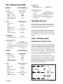
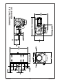
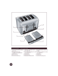
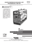
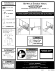
CHASSIS MOUNTED
GENERATOR
EC18000/A
EC22000/A
INSTALLATION AND
OPERATORS MANUAL
WINCO INC.
225 S. CORDOVA AVE.
LECENTER, MN 56057
507-357-6821
SERVICE DEPT.
507-357-6831
SAVE THESE INSTRUCTIONS
This manual contains important instructions that
should be followed during installation and maintenance of the generator and battery. Read and
understand all instructions in the manual before
starting and operating the generator set.
USING THE MANUAL
Congratulations on your choice of a Winco generator set. You have selected a high-quality, precision
engineered generator set designed and tested to
give you years of satisfactory service.
To get the best performance from your new engine
generator set, it is important that you carefully read
and follow the operating instructions in this manual.
Should you experience a problem please follow the
“Troubleshooting Hints” near the end of this manual.
The warranty listed in the manual describes what
you can expect from WINCO should you need service assistance in the future.
COPY YOUR MODEL AND
SERIAL NUMBER HERE
No other WINCO generator has the same serial
number as yours. It is important that you record
the number and other vital information here. If you
should ever need to contact us on this unit it will help
us to respond to your needs faster.
MODEL__________________________________
SERIAL NUMBER_________________________
PURCHASE DATE_________________________
DEALER_________________________________
DEALER PHONE # ________________________
TABLE OF CONTENTS
INTRODUCTION
i
SAFETY INFORMATION1
UNIT SPECIFICATIONS
2
UNIT CAPABILITIES
2
PREPARING THE UNIT
Unpacking the Unit
3
INSTALLATION
4
Ventilation
4
Gas Supply
4
Lubrication
5
Battery Installation
5
INITIAL START UP
5
Basic Operation
6
CONNECTING The LOADS
7
ENGINE CARE
8
GENERATOR CARE
8
TROUBLESHOOTING
9
EC18000 OUTLINE DWG10
EC22000 OUTLINE DWG11
OPTION FUEL TANK INSTALLATION12
WARRANTY INFORMATION18
PROPER USE AND INSTALLATION
You must be sure your new engine generator set is:
* Properly serviced before starting.
* Operated in a well ventilated area.
* Properly exhausted and gases safely
dispersed.
* Operated only for its designed purposes.
* Used only by operators who understand
its operation.
* Properly maintained.
SAFETY INFORMATION
2. FIRE HAZARD - Gasoline and other fuels present
a hazard of possible explosion and/or fire.
This engine generator set has been designed and
manufactured to allow safe, reliable performance.
Poor maintenance, improper or careless use can
result in potentially deadly hazards; from electrical
shock, exhaust gas asphyxiation, or fire. Please read
all safety instructions carefully before installation or
use. Keep these instructions handy for future reference. Take special note and follow all warnings on
the unit labels and in the manuals.
a. Do not refuel when the engine is running or hot.
b. Keep fuel containers out of reach of children.
c. Do not smoke or use open flame near the
generator set or fuel tank.
d. Keep a fire extinguisher nearby and know its
proper use. Fire extinguishers rated ABC by
NFPA are appropriate.
e. Store fuel only in an approved container, and
only in a well ventilated area.
ANSI SAFETY DEFINITIONS
***********************************************************
3. DEADLY EXHAUST GAS - Exhaust fumes from
any gasoline engine contain carbon monoxide, an
invisible, odorless and deadly gas that must be mixed
with fresh air.
DANGER:
DANGER indicates an imminently hazardous situation which, if not avoided, will result in death or
serious injury. This signal word is to be limited to the
most extreme situations.
***********************************************************
a. Operate only in well ventilated areas.
b. Never operate indoors.
c. Never operate the unit in such a way as to
allow exhaust gases to seep back into closed
rooms (i.e. through windows, walls, floors).
***********************************************************
WARNING:
WARNING indicates a potentially hazardous situation
which, if not avoided, could result in death or serious
injury.
***********************************************************
4. NOISE HAZARD - Excessive noise is not only tiring, but continual exposure can lead to loss of hearing.
a Use hearing protection when working around
this equipment for long periods of time.
b. Keep your neighbors in mind when using this equipment.
***********************************************************
CAUTION:
CAUTION indicates a potentially hazardous situation
which, if not avoided, may result in minor or moderate injury. It may also be used to alert against unsafe
practices.
***********************************************************
5. CLEANLINESS - Keep the generator and surrounding area clean.
a. Remove all grease, ice, snow or materials that
create slippery conditions around the unit.
b. Remove any rags or other materials that could
create a potential fire hazard.
c. Carefully clean up any gas or oil spills before
starting the unit.
NOTE:
CAUTION is also used on the unit labels and in this
manual to indicate a situation that could result in
serious damage or destruction of the equipment and
possible personal injury.
1. ELECTRICAL SHOCK - The output voltage present in this equipment can cause fatal electric shock.
This equipment must be operated by a responsible
person.
6. SERVICING EQUIPMENT All service, including the installation or replacement of service parts,
should be preformed only by a qualified technician.
a. Use only factory approved repair parts.
b. Do not work on this equipment when fatigued.
c. Never remove the protective guards, covers, or
receptacle panels while the engine is running.
d. Use extreme caution when working on
electrical components. Voltage from this
equipment can cause serious injury or death.
e. Always avoid hot mufflers, exhaust manifolds,
and engine parts. They can cause severe
burns instantly.
f. The use of the engine-generator set must
comply with all national, state, and local codes.
a. Do not allow anyone to operate the generator
without proper instruction.
b. Guard against electric shock.
c. Avoid contact with live terminals or receptacles.
d. Use extreme care if operating this unit in rain
or snow.
e. Use only three or four pronged grounded
receptacles and extension cords.
f. Be sure the unit is properly grounded
in accordance withapplicable codes.
60706-231
12124-00
UNIT SPECIFICATIONS
MODEL
Complete Unit
Weight (dry)
Dimensions LxWxH
EC18000VE/A
Owner Must Provide
Fuel Supply
Gasoline
Including Tank & Lines
Oil Type
SG SF, SH, SJ or higher
Oil Weight (general use) Synthetic 5W-30
See engine manual for additional information
Oil Capacity
2.5 Quarts
Generator Mecc Alte Spa
Model Number
S20F-230/A,
Surge Watts18000
Continuous Watts15000
Volts120/240
AMPs @ 240 Volts
62.5
AMPs @ 120 Volts125
TESTING POLICY
Engine Briggs & Stratton
Size
895 cc/OHV
Horse Power
31
Model 543477
Type -
2141 G1
Fuel Consumption
Gasoline
2.7 gal/hr
Starting System Electric Key Start
Voltage12V
Low Oil Protection Standard
Complete Unit
Weight (dry)
Dimensions LxWxH
Before any generator is shipped from the factory, it
is fully checked for performance. The generator is
loaded to its full capacity, and the voltage, current
and frequency are carefully checked.
Rated output of generator is based on engineering
tests of typical units, and is subject to, and limited
by, the temperature, altitude, fuel, and other conditions specified by the manufacturer of the applicable
engines.
326 LBS
34” X 21.2 x 24.1
UNIT CAPABILITIES
Owner Must Provide
Fuel Supply
Gasoline
Including Tank & Lines
Oil Type
SG SF, SH, SJ or higher
Oil Weight (general use) Synthetic 5W-30
See engine manual for additional information
Oil Capacity
2.5 Quarts
MODEL
GENERATOR CONNECTIONS
The diagram below represents the 15,000 watt generator. The capability of the unit is shown as follows:
“A” and “B” represent the 120 volt capability of the
generator in this case 7500 watts between both G1
to neutral and G3 to neutral. “C” represent the 240
volt capability of the generator, 15000 watts between
G1 and G3. This generator produces 120 and 240
volt, 60 Hz (Hertz), AC (Alternating Current).
EC22000VE/A
Generator Mecc Alte Spa
Model Number
ECP28-2L/2,
Surge Watts
22000
Continuous Watts19000
Volts120/240
AMPs @ 240 Volts
79
AMPs @ 120 Volts158
Check the appliance or tool nameplates for the current and voltage to ensure compatibility. Remember
that power utilized from C reduces the power available at both A and B and vice versa. The EC22000
utilizes the same format with “A” & “B” being 9500
watts and “C” being 19,000 watts
Engine Briggs & Stratton
Size
993 cc/OHV
Horse Power
35
Model 613477
Type -
0219 G1
Fuel Consumption
Gasoline
3.3 gal/hr
Starting System Electric Key Start
Voltage12V
Low Oil Protection Standard
12124-00
495 LBS
38” X 20.7 x 24.6
60706-231
STARTING ELECTRIC MOTORS
The heavy surge of current required for starting
motors is required for only an instant. The generator will not be damaged if it can bring the motor up
to speed in a few seconds of time. If difficulty is
experienced in starting motors, turn all other electrical loads off and if possible reduce the load on the
electric motor.
Electric motors require much more current (amps) to
start them than to run them. Some motors, particularly low cost split-phase motors, are very hard
to start and require 5 to 7 times as much current
to start them as to run them. Capacitor motors are
easier to start and usually require 2 to 4 times as
much current to start them as to run them. Repulsion Induction motors are the easiest to start and
require 1 1/2 to 2 1/2 times as much to start them as
to run them.
PREPARING THE UNIT
UNPACKING
Most fractional horsepower motors take about the
same amount of current to run them whether they
are Repulsion Induction (RI), Capacitor (Cap), or
Split-Phase (SP) type. The chart below shows the
approximate current required to start and run various
types and sizes of 120 volt 60 cycle electric motors
under average load conditions.
HP
AMPS
RUNNING
CAUTION: EQUIPMENT DAMAGE
THIS UNIT HAS BEEN SHIPPED WITHOUT OIL.
Failure to maintain the engine oil at the proper level
will result in serious engine damage.
When you unpack your new engine-generator set be
sure to remove all the information sheets and manuals from the carton.
STARTING AMPS
SP
CAP
1. This generator-set was in good order when
shipped. Inspect the generator-set promptly after
receiving it. If any damage is noted, notify the transportation company immediately; request proper procedures for filing a “concealed damage” claim. Title
to the equipment and responsibility for filing a claim
rests with you when a generator-set is sent F.O.B.
shipping point. Only you can legally file a claim.
RI
1/6
3.2
16 to 22
6 to 13
5 to 8
1/4
4.5
22 to 32
9 to 18
7 to 12
1/3
5.2
26 to 35
10 to 21
8 to 17
1/2
7.2
not made
14 to 29
11 to 18
1
13.0
not made
26 to 52
20 to 33
The figures given above are an average load such
as a blower or fan. If the electric motor is connected
to a hard starting load such as an air compressor, it
will require more starting current. If it is connected
to a light load, or no load such as a power saw, it will
require less starting current. The exact requirement
will also vary with the brand or design of the motor.
2. Before proceeding with the preparations of your
new generator-set for operation, take a couple of
minutes to ensure the unit you have received is the
correct model and review the specification pages in
this manual to ensure that this unit meets your job
requirements.
Self-exciting generators respond to severe overloading differently than utility power. When overloaded,
the engine is not able to supply enough power to
bring the electric motor up to operating speed. The
generator responds with high initial starting current,
but the engine speed drops sharply. The overload
may stall the engine. If allowed to operate at very
low speeds, the electric motor starting winding will
burn out in a short time. The generator winding
might also be damaged.
CAUTION: EQUIPMENT DAMAGE
RUNNING THE GENERATOR SET UNDER THESE
CONDITIONS MAY RESULT IN DAMAGING THE
GENERATOR STATOR AS WELL AS THE MOTOR
WINDING.
60706-231
12124-00
GASOLINE
INSTALLATION AND UNIT
PREPARATION
When using gasoline always use a good grade of
unleaded fuel. This engine is certified to operate on
unleaded gasoline with a pump octane rating of 86
or higher. Gasoline containing no more than 10%
ethanol (E10) or 5% methanol by volume may be
used. In addition methanol must contain co-solvents
and corrosion inhibitors. Use of fuels with content
of ethanol or methanol greater than shown above
may cause starting and/or performance problems.
Always ensure that the fuel is clean and free of all
impurities.
It is the customer’s responsiblilty to ensure
that all installations comply with all local,
state and national codes, including OHSA,
EPA and NEC.
CAUTION EQUIPMENT DAMAGE
These units must be mounted on a solid surface to
prevent the unit from vibrating and causing damage
to the engine or generator.
WARNING: FIRE DANGER
Gasoline and its fumes are VERY explosive when
proper precautions are not taken.
Before beginning the installation process recheck
the rating of the generator to be certain it can handle
the intended load. Plans for installation should be
prepared with proper attention to mechanical and
electrical engineering detail to assure a satisfactory
system installation. The information in this manual is
offered only as a guide to finalizing your installation
plans. As each installation is different no specifics
are provided in this manual
Never use gasoline that has been stored for an extended period of time as the fuel will lose its volatile
properties and you will be left with only the varnish
residue. This varnish like substance will clog the
carburetor and will not burn properly.
The use of fuel additives, such as STA-BIL, or an
equivalent will minimize the formation of fuel gum
deposits. If a unit has been out of operation for an
extended period of time it is best to drain old fuel
from the engine and replace with fresh fuel before
attempting to start.
VENTILATION
These engine generator sets use large amounts of
fresh air for cooling. When designing plans for your
installation special attention must be paid to the flow
of hot air from both the engine and the generator.
Both the engine and the generator must be supplied
with a constant flow of fresh air from the outside to
ensure they don’t overheat. Some provision must be
made to remove the hot air out of the enclosure. Ambient temperature around the unit should not exceed
1220F. Engine or generator failures resulting from
inadequate ventilation are considered abuse and not
covered by the generator or engine manufacturer’s
warranty.
These units have been designed and shipped without fuel tanks. This allows the customer to utilize
whatever size and type of tank they may desire, with
some limitations.
1. The fuel lift from the bottom of the tank to the
fuel inlet on the generator must not exceed 3 feet.
If a greater lift is required it may be necessary to
provide an additional electric fuel pump to ensure
the engine gets a sufficient flow of fuel.
2. Some states require the installation of a carbon
canister on the tank vent line. This is to prevent the
escape of fuel vapors in to atmosphere.
The engine exhaust from this engine must be vented
to the outside. When venting hot exhaust through
any type of flammable wall be sure to use exhaust
thimbles to prevent fires.
3. You need to have is a primer bulb in the fuel line
to prime the fuel from the tank to the fuel pump.
The vacuum fuel pump on the engine will not draw
the fuel up from the tank until the line has been
properly primed.
WARNING: PERSONAL INJURY
Failure to properly vent the exhaust out of an enclosure can and will kill you. Carbon monoxide is both
invisible and orderless and can build up very rapidly
in any enclosure not properly vented.
12124-00
4. In all cases the minimum fuel line size must be
1/4” or larger line. And the fuel line must be certified
for use with unleaded gasoline.
60706-231
LUBRICATION
BATTERY CHARGING
Before starting the engine, fill the crankcase to the
proper level with a good quality oil. The recommended grade of oil and quantity of oil required is
listed in the engine operator’s manual. The necessity of using the correct oil and keeping the crankcase full cannot be overemphasized. Engine failures
resulting from inadequate or improper lubricant are
considered abuse and not covered by the generator
or engine manufacturer’s warranty.
Units equipped with electric start have a small flywheel charger built into the engine flywheel assembly for recharging the starting battery. This flywheel
charger generates a small AC current that passes
through a diode assembly to produce a DC charging current of about 1 to 3 AMPS. This circuit is not
designed to be used as a battery charging circuit to
recharge dead batteries.
OIL ALERT SYSTEM
BATTERY INSTALLATION
These engine generator sets come equipped
standard with the Briggs & Stratton low oil pressure
shutdown system. The low oil shutdown system is
designed to prevent severe damage caused by an
insufficient amount of oil in the crankcase. However
if the unit is repeatedly allowed to shutdown on low
oil pressure progressive damage will be done to
the engine shortening the engine’s life. The engine
switch will remain in the “ON” position when the unit
is shutdown by the low oil pressure system.
You will need to connect this unit to a battery to
operate it. Cables have not been provided as length
are going to vary depending on your installation.
These engines are all negative ground. The positive battery cable must be connected to the open
large terminal on the start solenoid (This terminal
may have a small 16 GA. wire on it for the charging
circuit). The negative cable should be attached to a
good ground on the engine. This is usually one of
the starter mounting studs.
INITIAL START UP
A twelve volt battery, rated at 300 CCA or larger is
recommended for this electric start engine generator
set. Follow the battery manufacturer’s recommendations for servicing and charging prior to use.
The throttle control on these generators is preset
and locked to operate at 3600 RPM (nominal) with
no load speed set at 3690 RPM. Only a trained
service technician should be allowed to adjust this
speed setting.
CAUTION: EQUIPMENT DAMAGE
These electric start engines are NEGATIVE
GROUND. Use extreme caution when connecting
the battery. Connect the NEGATIVE battery terminal
to GROUND.
NOTICE: ENGINE START LOCKOUT
This unit will not start and run if it is low on oil.
The lubricating oil level must be at the full mark
before the engine will start and run.
For your safety always connect the positive battery
cable to the “BAT+” terminal first. Then connect the
negative battery cable to the “BAT-” terminal. Make
sure all connections are clean and tight. Reverse
the sequence when disconnecting, disconnect the
negative cable first. These engines produce enough
direct current to keep a battery charged under normal operating conditions, but were not intended to
be used as a battery charger.
WARNING: PERSONAL INJURY
Lead acid batteries produce explosive hydrogen gas
when charging. Keep sparks, flames, and burning
cigarettes away from the battery. Ventilate the area
when charging or using the battery in an enclosed
space. Lead acid batteries contain sulfuric acid,
which causes severe burns. If acid contacts eyes,
skin or clothing, flush well with water. For contact
with eyes, get immediate medical attention.
60706-231
12124-00
BASIC OPERATION
STOPPING AND STORAGE
ELECTRIC STARTING
Turn the key to “OFF” position. Before extended
storage (over 30 days) certain precautions must be
taken to ensure the fuel doesn’t deteriorate and clog
the fuel system. Note: The use of a fuel additive,
such as STA-BIL or an equivalent will minimize the
formation of gum deposits during storage. Such an
additive may be added to gasoline in the engine’s
fuel tank or to gasoline in a storage container. If you
are going to store the unit for a long period of time
we recommend the following steps be taken.
CAUTION: EQUIPMENT DAMAGE
Always start the unit with the circuit breaker open,
never start with the load applied.Always keep the
battery charged, especially during cold weather
operation.
1. Turn on the fuel supply.
1. Remove the remaining fuel from the fuel tank
2. Using the primer bulb, make sure that the fuel is
pumped up to the fuel pump on the engine.
2. Start the engine and allow it to run until all the
fuel in the carburetor and the fuel lines has been
used up and the engine stops.
3. Move the choke to the full “ON” position for starting. A warm engine will require less choking than a
cold engine.
3. While the engine is warm, drain the oil and refill
with fresh oil.
4. Turn the key to the start position. The starter life
is improved by using shorter starting cycles with time
to cool off between cranking cycles. Do not operate the starter more than 15 seconds during each
minute. Repeat if necessary.
4. Remove the spark plug, pour approximately 1/2
ounce (15 cc) of engine oil into the cylinder and
crank slowly to distribute the oil. Replace the spark
plug.
5. When the engine starts, release the key and
open the choke gradually.
5. Clean dirt and chaff from cylinders, cylinder head
fins, blower housing, screen and muffler areas.
Store in a clean and dry area.
6. The engine should promptly come up to operating speed.
OPERATING SPEED
CAUTION: EQUIPMENT DAMAGE
The engine-generator must be run at the correct
speed in order to produce the proper electrical voltage and frequency.
Never permit the choke to remain on after the engine
has run for a short time. It is not necessary to choke
the engine when it is warm. Avoid over-choking.
CAUTION: EQUIPMENT DAMAGE
STARTING HINTS
The output voltage should be checked to ensure the
generator is working properly prior to connecting a
load to the generator. Failure to do so could result in
damage to equipment plugged into the unit and possible injury to the individual.
1. Cold weather
a. Use the proper oil for the temperature
expected.
b. Use fresh winter grade fuel. Winter grade
gasoline is blended to improve starting. Do not use summer gasoline.
All engines have a tendency to slow down when
a load is applied. When the electrical load is connected to the generator, the engine is more heavily
loaded, and as a result the speed drops slightly.
This slight decrease in speed, together with the
voltage drop within the generator itself, results in a
2. Hot weather
a. Use the proper oil for the temperature
expected.
b. Use only summer blended gasoline. Using gasoline left over from winter may cause the unit to vapor lock.
12124-00
60706-231
CONNECTING THE LOADS
slightly lower voltage when the generator is loaded
to its full capacity than when running no load. The
slight variation in speed also affects the frequency of
the output current. This frequency variation has no
appreciable effect in the operation of motors, lights
and most appliances. However, electronic equipment and clocks will be affected if correct RPM is not
maintained. See Load vs. Output chart.
CAUTION: EQUIPMENT DAMAGE
Failure to properly limit and balance the load applied
to the generator will cause the generator to produce
low voltage and may damage the engine generator
set. It may also cause severe damage to the loads
connected to the generator at that time. Improper
loading of the generator set constitutes abuse and
will not be covered by warranty.
Although individual units and models vary slightly,
the normal voltage and frequency of the engine-generator described in this manual are approximately as
follows, under varying loads:
A 60 amp receptacle (NEMA 14-60) has been provided to allow the connection of loads to the generator on the EC18000. This receptacle is a 4 wire
full load receptacle protected by a 60 amp breaker
mounted in the control box on top of the generator.
LOAD VS. OUTPUT
Generator
Load
Speed
(RPM)
Frequency
(Hz)
Voltage
None
3690
61.5
125V
Half
3600
60.0
120V
Full
3510
58.5
115V
On the EC22000 the load wiring must be wired
directly in the 80 amp breaker mounted in the control
box on the top of the generator When wiring directly
to the circuit breaker in the box be sure to connect a
neutral wire and ground wire to the appropriate locations in the control box.
The speed of the engine was carefully adjusted at
the factory so that the generator produces the proper
voltage and frequency. For normal usage, the speed
setting should not be changed. If the generator
is being run continuously on a very light load, it is
often advisable to lower the operating speed slightly.
Whenever making any speed adjustments check the
unit with a voltmeter or tachometer and be sure the
speed is correct.
Your individual loads must be protected by individual
circuit breakers mounted in some type of distribution
panel. This location will also be where you will install your neutral to ground bond. You must wire four
separate wires from the generator (2 -hot,1- neutral
and 1-ground) to the distribution panel.
Lower voltage may damage both the generator and
any load connected to it. Running the engine at excessively high speeds results in high voltage, which
may significantly shorten the life of appliances being
used.
APPLYING THE LOADS
Allow the engine to warm up for two or three minutes
before applying any load. This will allow the engine
to reach normal operating temperature and oil to
circulate throughout the engine. A short warm-up
time will permit the engine to work more efficiently
when the load is applied and will reduce the wear in
the engine, extending its life.
Output voltage should be checked periodically to
ensure continued proper operation of the generating plant and appliances. If the generator is not
equipped with a voltmeter, it can be checked with a
portable meter. Frequency can be checked by using
an electric clock with a sweep second hand. Timed
against a wrist watch or a stop watch, the clock
should be correct within +/- 2 seconds per minute.
If a large motor is being started or multiple motors
are being started, they should be started individually
and the largest should be started first.
CAUTION: EQUIPMENT OVERLOAD
Keep the generator load within the generator and
receptacle nameplate rating. Overloading may
cause damage to the generator and/or the loads .
Most electric tools and appliances will have the voltage and amperage requirements on their individual
60706-231
12124-00
nameplates. When in doubt consult the manufacturer
or a local electrician. The nameplate amperage rating for electric motors can be misleading. See “Starting Electric Motors” in Unit Capabilities (page 4).
3. Dual Element Air Filter: Clean and/or replace
foam pre-cleaner and air filter every 12 months or
100 hours. Service more often under dusty conditions.
a. Loosen screws and remove cover and air cleaner assembly from base.
b. Remove foam pre-cleaner by sliding it off the paper cartridge.
c. Wash foam pre-cleaner in liquid detergent and water.
d. Wrap foam pre-cleaner in cloth and squeeze dry.
e. Saturate foam pre-cleaner in engine oil. Squeeze to remove excess oil.
f. Clean Air filter.
g. Install foam pre-cleaner over air filter.
h. Re-install the Air Filter assembly.
Reassemble cover and screw down tight.
These engine-generator sets are inherently self regulating based on engine speed. The engine governor
will automatically adjust itself to the load. No harm
to the generator will result if it is operated with no
load connected. The generator is a limited source of
electrical power, therefore pay special attention to the
generator ratings.
GROUNDING
All units must be properly grounded. Different installations will require different grounding requirements.
Depending on your installation ensure that the
ground meets your governing codes.
Do not use petroleum solvents, such as kerosene,
to attempt to clean the cartridge. They may cause
deterioration of the cartridge. DO NOT OIL CARTRIDGE. DO NOT USE PRESSURIZED AIR TO
CLEAN OR DRY CARTRIDGE.
ENGINE CARE
If major engine service or repair is required contact
an authorized engine service center. The manufacturer of these engines has established an excellent
world-wide engine service organization. Engine service is very likely available from a nearby authorized
dealer or distributor. Check the yellow pages of your
local telephone directory under “Engines-Gasoline”
for the closest engine repair center or ask the dealer
from whom you purchased the power plant.
4. Spark Plug: Clean and reset gap at .030” every
12 months or 100 hours of operation. Do not blast
clean spark plug. Clean by scraping or wire brushing and washing with a commercial solvent. Poor
spark will occur if terminal does not fit firmly on spark
plug. If this happens reform the terminal to fit firmly
on spark plug tip.
1. Change the oil after the first month or 5 hours of
operation and every 12 months or 100 hours thereafter under normal operating conditions. Change
engine oil every 50 hours of operation if the engine
is operated under heavy load, or in high ambient
temperatures.
a. Remove oil drain plug at base of the engine and drain the oil with the engine warm.
b. Replace oil drain plug.
c. Remove oil filler plug and refill with new oil.
Refer to the table in the engine manual for the proper grade of oil based on your
operating temperature.
d. Replace filler plug.
5. Carbon Canister: Designed to collect, store,
and dispose of fuel vapors created in the fuel tank /
fuel system. Remove and clean or replace the filter
on the canister when maintaining your air filter. The
canister will last the life of the unit.
GENERATOR CARE
Proper care and maintenance of the generator is
necessary to ensure a long trouble free life.
1. Exercising The Generator - The generator
should be operated every three to four weeks. It
should be operated for a period of time sufficient to
warm the unit up and to dry out any moisture that
has accumulated in the windings. If left, this moisture can cause corrosion in the winding. Frequent
operation of the engine generator set will also
ensure that the set is operating properly should it be
needed in an emergency.
2. Checking the Oil Level: The oil level must always be checked before the engine is started. Take
care to remove any dirt or debris from around the
oil fill plug before removing. Be sure the oil level is
maintained. Fill to the “FULL” mark on the dipstick.
12124-00
60706-231
2. Generator Maintenance - Any major generator
service including the installation or replacement of
parts should be performed only by a qualified electrical service technician. USE ONLY FACTORY APPROVED REPAIR PARTS.
TROUBLESHOOTING
HINTS
a.
b.
PROBLEM (SYMPTOMS) POSSIBLE CAUSES
———————————————————————
Won’t Start
*Low Oil Level.
*Fouled spark plug.
*Out of fuel.
*Start switch in Off position.
———————————————————————
Voltage too low *Engine speed is too low.
*Generator overloaded.
*Defective stator.
*Defective rotor (field).
———————————————————————
Circuit Breaker *Defective load.
Trips *Defective receptacle.
———————————————————————
Voltage too high *Engine speed is too high.
———————————————————————
Generator *Overloaded.
overheating *Insufficient ventilation.
———————————————————————
No output voltage
*Short in load (disconnect).
*Broken or loose wire.
*Defective receptacle.
*No residual magnetism
(in generator).
*Defective stator.
*Defective rotor (field).
*Shorted capacitor.
*GFCI Receptacle tripped.
———————————————————————
Bearing - The bearing used in these
generators is a heavy duty double sealed ball bearing. They require no maintenance or
lubrication.
Receptacles - Quality receptacles have been
utilized. If a receptacle should become cracked or otherwise damaged, replace it.
Using damaged or cracked receptacles can be both dangerous to the operator and destructive to the equipment.
CLEANING
Remove dirt and debris with a cloth or brush. DO
NOT use high pressure spray to clean either the
engine or the generator. This high pressure spray
could contaminate the fuel system and the generator
components.
1. Keep the air inlet screen on both the engine and
generator free of any dirt or debris to ensure proper
cooling. At least yearly remove the blower housing
on the engine and clean the chaff and dirt out of the
engine cooling fins and flywheel. Clean more often
if necessary. Failure to keep these areas clean may
cause overheating and permanent damage to the
unit.
2. Periodically clean muffler area to remove all
grass, dirt and combustible debris to prevent a fire.
3. On engine mufflers equipped with spark arresters,
the spark arrester must be removed every 50 hours
for cleaning and inspection. Replace if damaged.
60706-231
12124-00
EC18000VE/A
OUTLINE DRAWING
60706-231
10
12124-00
60706-231
11
12124-00
EC22000VE/A
OUTLINE DRAWING
INSTALLATION INSTRUCTIONS
OPTIONAL FUEL TANK KIT
EC18000VE & EC22000VE
3
2
1
4
5
COMPONENT LIST
REF. #
1
2
3
4
5
NOT SHOWN
PART #
81900-001
80900-000
16316-001
62397-001
62391-000
19018-411
DESCRIPTION
Carbon Canister Bracket
Carbon Canister
15 Gallon Fuel Tank
Fuel Cap with Gauge
Primer Bulb
Bag of Parts
QTY.
1
1
1
1
1
1
CUSTOMER SUPPLIED 1/4” AND 5/16” FUEL HOSE CONNECTED TO THE
FUEL TANK IS NOT PROVIDED IN THIS KIT.
12124-00
12
60706-231
STEP 1
•
Account for all components, hardware and fasteners.
FASTENERS & MISC. COMPONENTS
(not shown in actual size)
6
7
11
8
14
13
12
9
15
10
HARDWARE & FASTENER LIST
REF #
PART #
DESCRIPTION
QTY
6
40078-000
1/4” Fuel Hose
36”
7
40077-000
3/16” Fuel Hose
34”
8
62999-004
Black Hose Clamp .69” OD
4
9
62999-001
Red Hose Clamp .5”OD
4
10
62999-005
Green Hose Clamp .41” OD
3
11
98435-001
Hose Fitting Elbow
1
12
62409-000
Bushing
1
13
62173-001
5/16” Self-Tapping Screw
2
14
98590-003
1/8” - 5/16” X 1/4” - 7/16” Hose Reducer
1
15
40079-000
5/16” Fuel Hose
8”
60706-231
13
12124-00
STEP 2
•
•
Attach the carbon canister bracket (ref. 1) using the two self-tapping screws
(ref.13)
Slide the carbon canister (ref. 2) up into the carbon canister bracket (ref.1) and
then slide it down until it is locked in place.
STEP 3
•
•
•
Mount fuel tank (ref. 3) in a suitable location to ensure proper flow of fuel. The
fuel tank must be mounted to a bracket to allow access to the shut-off valve. Bolt
holes are provided on the bottom of the fuel tank for mounting to a stable structure. Use 3/8-16 X ? bolts. The length will vary depending on the mounting structure. NOTE: When mounting the fuel tank below the level of the engine an additional fuel pump may be required for a lift of 3 feet or more from the bottom of the
fuel tank to the fuel pump on the engine. Hose lengths may have to be adjusted
for your application.
Install bushing (ref. 12) and hose fitting elbow (ref. 11) into the top of the fuel tank.
Install fuel cap with gauge (ref.4) on top of the fuel tank.
12124-00
14
60706-231
STEP 4
•
•
Route customer supplied 1/4” fuel line from fuel tank to engine and attach the fuel
line to the primer bulb (ref. 5) with red hose clamps. Attach 1/4” fuel hose (ref. 6)
to the other side of the primer bulb (ref. 5) with red hose clamp (ref. 9) and route to
the fuel filter (ref. A) on the engine. See step 5 below.
Attach 1/4” fuel hose (ref. 6) to the fuel filter (ref. A) on the engine using red hose
clamp (ref. 9).
STEP 5
•
•
•
Below is your fuel supply connection point on the engine. Fuel filter (ref. A) is
where you connect the fuel line (ref. 6) from Step 4.
NOTE: Each installation may vary. Your fuel line lengths may vary depending on
your installation requirements.
DANGER: Do not allow fuel lines to lay directly on “HOT” surfaces! This
may cause a fire.
A
60706-231
15
12124-00
STEP 6
•
Locate the small plastic bag that came with the Briggs & Stratton engine operators
manual. You will use the plastic connector (ref. B) in step 6. You can discard the
other part as it is not needed in this application.
B
STEP 7
•
•
•
Slide black hose clamps (ref. 8) onto 5/16” fuel hose (ref. 15) by compressing
them with a pliers. Push hose (ref. 8) onto carbon canister nipple marked PURGE
and move the clamp into position at the end of the hose.
Twist and push hose reducer (ref. 14) onto hose (ref. 15) and move clamp into
position at the end of the hose. NOTE: You can use a small amount of vegetable
oil on the hoses to ease in their connection.
Repeat process for 3/16” hose (ref. 7). This will connect to the engine hose in step
8.
14
10
B
10
8
8
7
15
2
12124-00
16
60706-231
STEP 8
•
•
•
•
Locate the hose (ref. C) on the left side of the engine that has a plastic ball inserted in the end of it. Use a small screw driver to remove the ball.
Slide green hose clamp (ref. 10) over hose (ref. C) using a pliers.
Route hose assembly (built in step 7) from the carbon canister (ref. 2) to this hose
and insert the connector (ref. B) into hose (ref. C).
Slide green hose clamp down to the end of the hose clamping it to the connector
(ref. B).
C
STEP 9
•
•
Attach customer supplied 5/16” fuel hose to hose fitting elbow (ref. 11) on top of
the fuel tank. See step 4 for illustration.
Route hose (ref. D) to the carbon canister (ref. 2) and connect to the nipple
marked TANK using black hose clamp (ref. 8).
60706-231
17
12124-00
24 MONTH LIMITED WARRANTY
WINCO, Incorporated warrants to the original purchaser for 24 months that goods
manufactured or supplied by it will be free from defects in workmanship and material,
provided such goods are installed, operated and maintained in accordance with WINCO
written instructions.
WINCO’s sole liability, and Purchaser’s sole remedy for a failure under this warranty,
shall be limited to the repair of the product. At WINCO’s option, material found to be
defective in material or workmanship under normal use and service will be repaired or
replaced. For warranty service, return the product within 24 months from the date of
purchase, transportation charges prepaid, to your nearest WINCO Authorized Service
Center or to WINCO, Inc. at LeCenter Minnesota.
THERE IS NO OTHER EXPRESS WARRANTY.
To the extent permitted by law, any and all warranties, including those of merchantability
and fitness for a particular purpose, are limited to 24 months from date of purchase. In
no event is WINCO liable for incidental or consequential damages.
Note: Some states do not allow limitation on the duration of implied warranty and some
states do not allow the exclusion or limitation of incidental or consequential damages, so
the above limitations may not apply in every instance. This warranty gives you specific
legal rights which may vary from state to state.
WINCO reserves the right to change or improve it products without incurring any obligations to make such changes or improvements on products purchased previously.
EXCLUSIONS:
WINCO does not warrant Engines. Engines are covered exclusively by the warranties
of their respective manufacturers.
WINCO does not warrant Batteries, or Other Component Parts that are warranted by
their respective manufacturers.
WINCO does not warrant modifications or alterations which were not made by WINCO
Inc.
WINCO does not warrant products which have been subjected to misuse and/or negligence or have been involved in an accident.
This warranty does not include travel time, mileage or labor for removal or reinstallation
of a Winco product from its application.
12124-00
18
60706-231