1
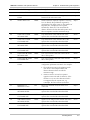
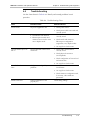
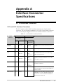
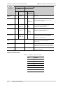
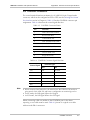
ASMi-52L Installation and Operation Manual
Appendix A Interface Connector Specifications
A.2 CONTROL Connector
The control terminal interface terminates in a V.24/RS-232 9-pin D-type female
connector, which can be configured as DCE or DTE (see the Selecting the Control
Port Interface section in Chapter 4). Table A-3 lists the CONTROL connector pin
assignments. Table A-4 describes the control signal direction.
Table A-3. CONTROL Connector Pinout
Pin
Function
1
Data Carrier Detect (DCD)
2
Receive Data (RD)
3
Transmit Data (TD)
4
Data Terminal Ready (DTR)
5
Ground (GND)
6
Data Set Ready (DSR)
7
Request To Send (RTS)
8
Clear To Send (CTS)
9
Ring Indicator (RI)
Table A-4. CONTROL Connector Signal Direction
Control Signal
Note
Interface Type
DCE
DTE
CTS
Out
Not Used
DCD
Out
Out
DSR
Out
Out
DTR
In
In
RI
Not Used
In
RTS
In
In
• When connected and turned on, the terminal sets the DTR line ON (active) to
gain control of the ASMi-52L and starts a configuration or monitoring session.
• In DTE mode, the DSR signal follows the RI signal
• In DCE mode, the DSR signal follows the DTR signal
When connecting a dial-out modem to the CONTROL port for the alarm
reporting, a cross cable must be used. Table A-5 pinout of a typical cross cable
with two male DB-9 connectors.
CONTROL Connector
A-3