1
Installation and Operation Manual
Egate-100
Channelized Ethernet
Gateway
Version 1.0
Egate-100
Channelized Ethernet Gateway
Version 1.0
Installation and Operation Manual
Notice
This manual contains information that is proprietary to RAD Data Communications Ltd. ("RAD"). No
part of this publication may be reproduced in any form whatsoever without prior written approval by
RAD Data Communications.
Right, title and interest, all information, copyrights, patents, know-how, trade secrets and other
intellectual property or other proprietary rights relating to this manual and to the Egate-100 and any
software components contained therein are proprietary products of RAD protected under international
copyright law and shall be and remain solely with RAD.
Egate-100 is a registered trademark of RAD. No right, license, or interest to such trademark is granted
hereunder, and you agree that no such right, license, or interest shall be asserted by you with respect
to such trademark.
You shall not copy, reverse compile or reverse assemble all or any portion of the Manual or the
Egate-100. You are prohibited from, and shall not, directly or indirectly, develop, market, distribute,
license, or sell any product that supports substantially similar functionality as the Egate-100, based on
or derived in any way from the Egate-100. Your undertaking in this paragraph shall survive the
termination of this Agreement.
This Agreement is effective upon your opening of the Egate-100 package and shall continue until
terminated. RAD may terminate this Agreement upon the breach by you of any term hereof. Upon
such termination by RAD, you agree to return to RAD the Egate-100 and all copies and portions
thereof.
For further information contact RAD at the address below or contact your local distributor.
International Headquarters
RAD Data Communications Ltd.
U.S. Headquarters
RAD Data Communications Inc.
24 Raoul Wallenberg St.
Tel Aviv 69719 Israel
Tel: 972-3-6458181
Fax: 972-3-6498250
E-mail: [email protected]
900 Corporate Drive
Mahwah, NJ 07430 USA
Tel: (201) 529-1100, Toll free: 1-800-444-7234
Fax: (201) 529-5777
E-mail: [email protected]
© 2004-2005 RAD Data Communications Ltd.
Publication No. 405-200-09/05
Limited Warranty
RAD warrants to DISTRIBUTOR that the hardware in the Egate-100 to be delivered hereunder shall be
free of defects in material and workmanship under normal use and service for a period of twelve (12)
months following the date of shipment to DISTRIBUTOR.
If, during the warranty period, any component part of the equipment becomes defective by reason of
material or workmanship, and DISTRIBUTOR immediately notifies RAD of such defect, RAD shall have
the option to choose the appropriate corrective action: a) supply a replacement part, or b) request
return of equipment to its plant for repair, or c) perform necessary repair at the equipment's location.
In the event that RAD requests the return of equipment, each party shall pay one-way shipping costs.
RAD shall be released from all obligations under its warranty in the event that the equipment has been
subjected to misuse, neglect, accident or improper installation, or if repairs or modifications were
made by persons other than RAD's own authorized service personnel, unless such repairs by others
were made with the written consent of RAD.
The above warranty is in lieu of all other warranties, expressed or implied. There are no warranties
which extend beyond the face hereof, including, but not limited to, warranties of merchantability and
fitness for a particular purpose, and in no event shall RAD be liable for consequential damages.
RAD shall not be liable to any person for any special or indirect damages, including, but not limited to,
lost profits from any cause whatsoever arising from or in any way connected with the manufacture,
sale, handling, repair, maintenance or use of the Egate-100, and in no event shall RAD's liability
exceed the purchase price of the Egate-100.
DISTRIBUTOR shall be responsible to its customers for any and all warranties which it makes relating
to Egate-100 and for ensuring that replacements and other adjustments required in connection with
the said warranties are satisfactory.
Software components in the Egate-100 are provided "as is" and without warranty of any kind. RAD
disclaims all warranties including the implied warranties of merchantability and fitness for a particular
purpose. RAD shall not be liable for any loss of use, interruption of business or indirect, special,
incidental or consequential damages of any kind. In spite of the above RAD shall do its best to provide
error-free software products and shall offer free Software updates during the warranty period under
this Agreement.
RAD's cumulative liability to you or any other party for any loss or damages resulting from any claims,
demands, or actions arising out of or relating to this Agreement and the Egate-100 shall not exceed the
sum paid to RAD for the purchase of the Egate-100. In no event shall RAD be liable for any indirect,
incidental, consequential, special, or exemplary damages or lost profits, even if RAD has been advised of
the possibility of such damages.
This Agreement shall be construed and governed in accordance with the laws of the State of Israel.
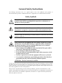
General Safety Instructions
The following instructions serve as a general guide for the safe installation and operation of
telecommunications products. Additional instructions, if applicable, are included inside the manual.
Safety Symbols
Warning
This symbol may appear on the equipment or in the text. It indicates
potential safety hazards regarding product operation or maintenance to
operator or service personnel.
Danger of electric shock! Avoid any contact with the marked surface while
the product is energized or connected to outdoor telecommunication lines.
.
Protective earth: the marked lug or terminal should be connected to the building
protective earth bus.
Warning
Some products may be equipped with a laser diode. In such cases, a label
with the laser class and other warnings as applicable will be attached near
the optical transmitter. The laser warning symbol may be also attached.
Please observe the following precautions:
• Before turning on the equipment, make sure that the fiber optic cable is
intact and is connected to the transmitter.
• Do not attempt to adjust the laser drive current.
• Do not use broken or unterminated fiber-optic cables/connectors or look
straight at the laser beam.
• The use of optical devices with the equipment will increase eye hazard.
• Use of controls, adjustments or performing procedures other than those
specified herein, may result in hazardous radiation exposure.
ATTENTION: The laser beam may be invisible!
In some cases, the users may insert their own SFP laser transceivers into the product. Users are alerted
that RAD cannot be held responsible for any damage that may result if non-compliant transceivers are
used. In particular, users are warned to use only agency-approved products that comply with the local
laser safety regulations for Class 1 laser products.
Always observe standard safety precautions during installation, operation and maintenance of this
product. Only qualified and authorized service personnel should carry out adjustment, maintenance or
repairs to this product. No installation, adjustment, maintenance or repairs should be performed by
either the operator or the user.
Handling Energized Products
General Safety Practices
Do not touch or tamper with the power supply when the power cord is connected. Line voltages may
be present inside certain products even when the power switch (if installed) is in the OFF position or a
fuse is blown. For DC-powered products, although the voltages levels are usually not hazardous,
energy hazards may still exist.
Before working on equipment connected to power lines or telecommunication lines, remove jewelry
or any other metallic object that may come into contact with energized parts.
Unless otherwise specified, all products are intended to be grounded during normal use. Grounding is
provided by connecting the mains plug to a wall socket with a protective earth terminal. If an earth lug
is provided on the product, it should be connected to the protective earth at all times, by a wire with a
diameter of 18 AWG or wider. Rack-mounted equipment should be mounted only in earthed racks
and cabinets.
Always make the ground connection first and disconnect it last. Do not connect telecommunication
cables to ungrounded equipment. Make sure that all other cables are disconnected before
disconnecting the ground.
Connection of AC Mains
Make sure that the electrical installation complies with local codes.
Always connect the AC plug to a wall socket with a protective ground.
The maximum permissible current capability of the branch distribution circuit that supplies power to
the product is 16A. The circuit breaker in the building installation should have high breaking capacity
and must operate at short-circuit current exceeding 35A.
Always connect the power cord first to the equipment and then to the wall socket. If a power switch is
provided in the equipment, set it to the OFF position. If the power cord cannot be readily
disconnected in case of emergency, make sure that a readily accessible circuit breaker or emergency
switch is installed in the building installation. For IT power distribution systems, the switch must
disconnect both holes simultaneously.
Connection of DC Mains
Unless otherwise specified in the manual, the DC input to the equipment is floating in reference to the
ground. Any single pole can be externally grounded. Due to the high current capability of DC mains
systems, care should be taken when connecting the DC supply to avoid short-circuits and fire hazards.
DC units should be installed in a restricted access area, i.e. an area where access is authorized only to
qualified service and maintenance personnel. Make sure that the DC supply is electrically isolated
from any AC source and that the installation complies with the local codes.
The maximum permissible current capability of the branch distribution circuit that supplies power to
the product is 16A. The circuit breaker in the building installation should have high breaking capacity
and must operate at short-circuit current exceeding 35A.
Before connecting the DC supply wires, ensure that power is removed from the DC circuit. Locate the
circuit breaker of the panel board that services the equipment and switch it to the OFF position. When
connecting the DC supply wires, first connect the ground wire to the corresponding terminal, then the
positive pole and last the negative pole. Switch the circuit breaker back to the ON position.
A readily accessible disconnect device that is suitably rated and approved should be incorporated in
the building installation. If the DC mains is floating, the switch must disconnect both poles
simultaneously.
Connection of Data and Telecommunications Cables
Data and telecommunication interfaces are classified according to their safety status.
The following table lists the status of several standard interfaces. If the status of a given port differs from
the standard one, a notice will be given in the manual.
Ports
Safety Status
V.11, V.28, V.35, V.36, RS-530,
X.21, 10 BaseT, 100 BaseT,
Unbalanced E1, E2, E3, STM, DS-2,
DS-3, S-Interface ISDN, Analog voice
E&M
SELV
xDSL (without feeding voltage),
Balanced E1, T1, Sub E1/T1
TNV-1 Telecommunication Network Voltage-1:
FXS (Foreign Exchange Subscriber)
TNV-2 Telecommunication Network Voltage-2:
Safety Extra Low Voltage:
Ports which do not present a safety hazard. Usually
up to 30 VAC or 60 VDC.
Ports whose normal operating voltage is within the
limits of SELV, on which overvoltages from
telecommunications networks are possible.
Ports whose normal operating voltage exceeds the
limits of SELV (usually up to 120 VDC or telephone
ringing voltages), on which overvoltages from
telecommunication networks are not possible. These
ports are not permitted to be directly connected to
external telephone and data lines.
FXO (Foreign Exchange Office), xDSL
(with feeding voltage), U-Interface
ISDN
TNV-3 Telecommunication Network Voltage-3:
Ports whose normal operating voltage exceeds the
limits of SELV (usually up to 120 VDC or telephone
ringing voltages), on which overvoltages from
telecommunication networks are possible.
Always connect a given port to a port of the same safety status. If in doubt, seek the assistance of a
qualified safety engineer.
Always make sure that the equipment is grounded before connecting telecommunication cables. Do
not disconnect the ground connection before disconnecting all telecommunications cables.
Some SELV and non-SELV circuits use the same connectors. Use caution when connecting cables.
Extra caution should be exercised during thunderstorms.
When using shielded or coaxial cables, verify that there is a good ground connection at both ends. The
earthing and bonding of the ground connections should comply with the local codes.
The telecommunication wiring in the building may be damaged or present a fire hazard in case of
contact between exposed external wires and the AC power lines. In order to reduce the risk, there are
restrictions on the diameter of wires in the telecom cables, between the equipment and the mating
connectors.
Caution
Attention
To reduce the risk of fire, use only No. 26 AWG or larger telecommunication line cords.
Pour réduire les risques s’incendie, utiliser seulement des conducteurs de
télécommunications 26 AWG ou de section supérieure.
Some ports are suitable for connection to intra-building or non-exposed wiring or cabling only. In such
cases, a notice will be given in the installation instructions.
Do not attempt to tamper with any carrier-provided equipment or connection hardware.
Electromagnetic Compatibility (EMC)
The equipment is designed and approved to comply with the electromagnetic regulations of major
regulatory bodies. The following instructions may enhance the performance of the equipment and will
provide better protection against excessive emission and better immunity against disturbances.
A good earth connection is essential. When installing the equipment in a rack, make sure to remove all
traces of paint from the mounting points. Use suitable lock-washers and torque. If an external
grounding lug is provided, connect it to the earth bus using braided wire as short as possible.
The equipment is designed to comply with EMC requirements when connecting it with unshielded
twisted pair (UTP) cables. However, the use of shielded wires is always recommended, especially for
high-rate data. In some cases, when unshielded wires are used, ferrite cores should be installed on
certain cables. In such cases, special instructions are provided in the manual.
Disconnect all wires which are not in permanent use, such as cables used for one-time configuration.
The compliance of the equipment with the regulations for conducted emission on the data lines is
dependent on the cable quality. The emission is tested for UTP with 80 dB longitudinal conversion loss
(LCL).
Unless otherwise specified or described in the manual, TNV-1 and TNV-3 ports provide secondary
protection against surges on the data lines. Primary protectors should be provided in the building
installation.
The equipment is designed to provide adequate protection against electro-static discharge (ESD).
However, it is good working practice to use caution when connecting cables terminated with plastic
connectors (without a grounded metal hood, such as flat cables) to sensitive data lines. Before
connecting such cables, discharge yourself by touching earth ground or wear an ESD preventive wrist
strap.
FCC-15 User Information
This equipment has been tested and found to comply with the limits of the Class A digital device,
pursuant to Part 15 of the FCC rules. These limits are designed to provide reasonable protection
against harmful interference when the equipment is operated in a commercial environment. This
equipment generates, uses and can radiate radio frequency energy and, if not installed and used in
accordance with the Installation and Operation manual, may cause harmful interference to the radio
communications. Operation of this equipment in a residential area is likely to cause harmful
interference in which case the user will be required to correct the interference at his own expense.
Canadian Emission Requirements
This Class A digital apparatus meets all the requirements of the Canadian Interference-Causing
Equipment Regulation.
Cet appareil numérique de la classe A respecte toutes les exigences du Règlement sur le matériel
brouilleur du Canada.
Warning per EN 55022 (CISPR-22)
Warning
This is a class A product. In a domestic environment, this product may cause
radio interference, in which case the user will be required to take adequate
measures.
Avertissement
Cet appareil est un appareil de Classe A. Dans un environnement résidentiel, cet
appareil peut provoquer des brouillages radioélectriques. Dans ces cas, il peut
être demandé à l’utilisateur de prendre les mesures appropriées.
Achtung
Dieses ist ein Gerät der Funkstörgrenzwertklasse A. In Wohnbereichen können
bei Betrieb dieses Gerätes Rundfunkströrungen auftreten, in welchen Fällen der
Benutzer für entsprechende Gegenmaßnahmen verantwortlich ist.
Declaration of Conformity
Manufacturer's Name:
RAD Data Communications Ltd.
Manufacturer's Address:
24 Raoul Wallenberg St.
Tel Aviv 69719
Israel
Declares that the product:
Egate-100
Product Name:
Conforms to the following standard(s) or other normative document(s):
EMC:
Safety:
EN 55022:1998 +
A1:2000, A2:2003
Information technology equipment – Radio disturbance
characteristics – Limits and methods of measurement.
EN 55024:1998 +
A1:2001, A2:2003
Information technology equipment – Immunity characteristics
– Limits and methods of measurement.
EN 60950-1:2001
Information technology equipment – Safety – Part 1:
General requirements.
Supplementary Information:
The product herewith complies with the requirements of the EMC Directive 89/336/EEC, the Low
Voltage Directive 73/23/EEC and the R&TTE Directive 1999/5/EC for wired equipment. The product
was tested in a typical configuration.
Tel Aviv, 28 July 2005
Haim Karshen
VP Quality
European Contact: RAD Data Communications GmbH, Otto-Hahn-Str. 28-30,
85521 Ottobrunn-Riemerling, Germany
Quick Start Guide
The installation of Egate-100 should be carried out by an experienced technician
only. If you are familiar with Egate-100, use this quick guide to prepare the unit for
operation.
1.
Installing Egate-100
Connecting the Interfaces
1. Connect the STM-1/OC-3 equipment to the fiber optic front panel connectors.
2. Connect the 1000BaseT or 1000BaseSx LAN to the DATA front panel
connector.
3. Use a straight cable to connect the control terminal to the front panel
CONTROL connector,
– or –
Connect a Telnet host, a PC running a Web-browsing application or a
RADview management station to the ETH MNG port.
Connecting the Power
•
Connect the power cable to the power connector on the Egate-100 front
panel.
The unit has no power switch. Operation starts when the power is applied
to the power connector.
2.
Configuring Egate-100
Configure Egate-100 via an ASCII terminal connected to the front panel CONTROL
port. Alternative configuration tools are described in Chapter 3.
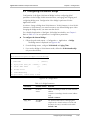
Starting a Terminal Session for the First Time
To start a terminal configuration session:
1. Connect an ASCII terminal to the Egate-100 CONTROL port (default settings
are: 115,200, N, 8, 1, Flow control: None).
2. Set the terminal emulator to VT100 emulation for optimal view of system menus.
3. If you are using Hyper Terminal, set the terminal mode to 132 column mode
for optimal view of system menus
(Properties>Settings>Terminal Setup>132 column mode).
Configuring Egate-100
1
Egate-100 Installation and Operation Manual
Quick Start Guide
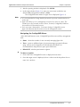
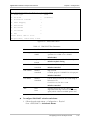
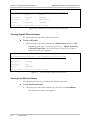
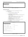
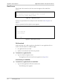
4. Power up Egate-100 and verify that the PWR LED on the front panel is On.
5. Verify the unit's correct startup by observing one of the following:
From the ASCII terminal verify that the Self-Test was successfully completed
Check the ALM LED on the front panel of the unit:
Off: no alarms present
On: device ALM is present.
6. If an alarm is present, check physical connections.
7. Press any key to display the user name and password entry form.
8. Enter your user name and password and proceed with the management
session.
Note
The Egate-100 default user names are su and user, default password is 1234. Only
su has permission to modify configuration parameters and download new software
versions.
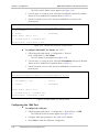
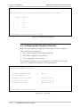
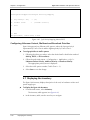
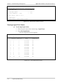
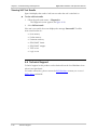
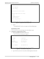
Configuring Egate-100 Elements
To configure Egate-100 elements:
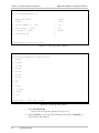
1. From the menu Main > Configuration > System > Management > Host IP,
configure the following parameters:
Host IP address
Host IP mask
Default gateway
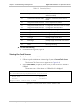
2. From the menu Main > Configuration > System > Management > Host IP >
Encapsulation, configure the following parameters:
•
Host tagging (untagged/tagged)
•
Host VLAN ID (for tagged only)
•
Host VLAN Priority (for tagged only)
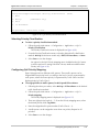
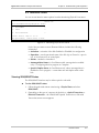
3. From the menu Main > Configuration > Physical Ports > GbE, configure the
following parameters:
•
Activation: Specify whether the network port is enabled or disabled.
•
Alarm: Specify whether to mask or unmask the alarms.
•
Autonegotiation: Enable or disable autonegotiation mode.
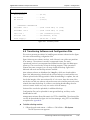
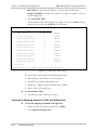
4. From the menu Main > Configuration > Physical Ports > SDH/SONET,
configure the following parameters:
2
•
Activation: Specify whether the network port is enabled or disabled.
•
Transmit Clock Source: Select the source of the system clock: Internal or
Loopback Timing.
•
Alarms: Specify whether to mask or unmask the alarms.
Configuring Egate-100
Egate-100 Installation and Operation Manual
•
Quick Start Guide
Mapping: Specify the E1 framed mode.
5. From the menu Main > Configuration > Logical Ports, define and configure
the required logical ports.
6. From the menu Main > Configuration > Application > Bridge, configure the
following bridge parameters:
•
Bridge mode: VLAN-Aware or VLAN-Unaware
•
Aging time
•
VLAN Membership (VLAN-Aware bridge only)
7. From the same menu, define the relevant bridge ports.
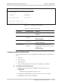
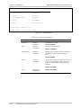
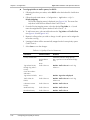
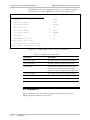
Parameter
Possible Values
Remarks
IP Address
0.0.0.0 to 255.255.255.255
Default: None
IP Mask
0.0.0.0 to 255.255.255.255
Default: None
Default Gateway
0.0.0.0 to 255.255.255.255
Default: None
Host Tagging
Tagged
Untagged
Specifies if the management
station is using tagged or
untagged frames. Egate-100
transmits in the same format,
even if the bridge is in VLANAware mode.
Default: Untagged
Host VLAN ID
1-4094
Sets the VLAN ID of the packets
sent by the host
Default: 1
Host VLAN priority
0-7
Sets VLAN priority for packets
sent by host. Relevant if Host
Tagging is set to Tagged.
Default: 0
Bridge Mode
VLAN-Aware
VLAN-Unaware
Selects Bridge operation mode.
Default: VLAN-Unaware
Configuring Egate-100
3
Quick Start Guide
4
Configuring Egate-100
Egate-100 Installation and Operation Manual
Contents
Chapter 1. Introduction
1.1 Overview..................................................................................................................... 1-1
Versions................................................................................................................................ 1-1
Applications.......................................................................................................................... 1-2
Features................................................................................................................................ 1-2
1.2 Physical Description..................................................................................................... 1-4
1.3 Functional Description................................................................................................. 1-5
Interfaces.............................................................................................................................. 1-5
Ethernet Access (Bridge)........................................................................................................ 1-6
Quality of Service ............................................................................................................... 1-10
Buffer Management ............................................................................................................ 1-12
Management ...................................................................................................................... 1-12
E1/T1 Timing ...................................................................................................................... 1-14
Diagnostics ......................................................................................................................... 1-14
1.4 Technical Specifications............................................................................................. 1-15
Chapter 2. Installation and Setup
2.1
2.2
2.3
2.4
Introduction................................................................................................................. 2-1
Site Requirements and Prerequisites ............................................................................ 2-1
Package Contents ........................................................................................................ 2-2
Equipment Needed ..................................................................................................... 2-2
Hand Tools and Kits.............................................................................................................. 2-2
Power Cable......................................................................................................................... 2-2
Cable and Connectors .......................................................................................................... 2-2
2.5 Connecting the Interfaces ............................................................................................ 2-3
Connecting the SDH/SONET Port ......................................................................................... 2-3
Connecting the GbE Port ...................................................................................................... 2-3
Connecting the Fast Ethernet Port ......................................................................................... 2-3
Connecting the Terminal....................................................................................................... 2-3
2.6 Connecting the Power ................................................................................................. 2-4
Chapter 3. Operation
3.1
3.2
3.3
3.4
Turning Egate-100 On ................................................................................................. 3-1
Controls and Indicators ................................................................................................ 3-1
Default Settings............................................................................................................ 3-2
Configuration Alternatives............................................................................................ 3-4
Managing via the Terminal Port............................................................................................. 3-4
Managing via ConfiguRAD .................................................................................................... 3-6
Managing via RADview-Lite .................................................................................................. 3-8
Obtaining a New Password ................................................................................................... 3-8
3.5 Overview of Menu Operations .................................................................................... 3-9
3.6 Turning Egate-100 Off ............................................................................................... 3-11
Egate-100 Installation and Operation Manual
i
Table of Contents
Chapter 4. Configuration
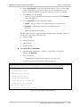
4.1 Configuration Sequence .............................................................................................. 4-1
4.2 Defining System Parameters......................................................................................... 4-1
Selecting the Clock Source.................................................................................................... 4-2
Entering Device Information.................................................................................................. 4-4
Configuring IP Host Parameters............................................................................................. 4-5
Configuring the Network Managers ....................................................................................... 4-7
Controlling User Access......................................................................................................... 4-8
Configuring Terminal Parameters ........................................................................................ 4-10
Configuring Alarm Masking ................................................................................................. 4-10
Entering Date and Time ...................................................................................................... 4-11
Entering Buffer Management Information ............................................................................ 4-11
4.3 Configuring Ports at the Physical Level ....................................................................... 4-14
Configuring the SDH/SONET Port ....................................................................................... 4-14
Configuring the 1GbE Port .................................................................................................. 4-18
Configuring the Fast Ethernet Port ....................................................................................... 4-19
4.4 Configuring the Logical Ports...................................................................................... 4-21
4.5 Configuring the Internal Bridge .................................................................................. 4-23
Using the Static MAC Table................................................................................................. 4-24
Configuring the Bridge Ports................................................................................................ 4-25
Configuring VLAN Membership........................................................................................... 4-27
4.6 Configuring QoS (Quality of Service).......................................................................... 4-30
Selecting Priority Classification ............................................................................................ 4-31
Configuring QoS Priority Mapping....................................................................................... 4-31
Configuring Unknown Unicast, Multicast and Broadcast Priorities........................................ 4-34
4.7 Displaying the Inventory ............................................................................................ 4-34
4.8 Transferring Software and Configuration Files ............................................................ 4-35
4.9 Resetting Egate-100 ................................................................................................... 4-38
Resetting to Factory Defaults ............................................................................................... 4-38
Resetting the Unit ............................................................................................................... 4-38
Chapter 5. Configuring a Typical Application
5.1 Application Requirements............................................................................................ 5-1
5.2 Configuring the System Parameters .............................................................................. 5-2
Configuring Parameters via ASCII Terminal............................................................................ 5-2
5.3 Configuring the Physical Ports ...................................................................................... 5-2
Configuring the SDH/SONET Port ......................................................................................... 5-3
Configuring the GbE Port ...................................................................................................... 5-3
Configuring the Fast Ethernet Port ......................................................................................... 5-3
5.4 Configuring the Logical Layer....................................................................................... 5-3
5.5 Configuring the Bridge ................................................................................................. 5-4
Configuring the Bridge Parameters ........................................................................................ 5-4
Configuring the Bridge Ports..................................................................................................5-4
Configuring the Bridge VLAN Membership ............................................................................ 5-5
ii
Egate-100 Installation and Operation Manual
Table of Contents
Chapter 6. Troubleshooting and Diagnostics
6.1 System Monitoring....................................................................................................... 6-1
Identifying Alarm and Event Sources...................................................................................... 6-2
Viewing Active Alarms .......................................................................................................... 6-2
Viewing the Event Log........................................................................................................... 6-5
Viewing the Clock Sources .................................................................................................... 6-8
6.2 Interface Status ............................................................................................................ 6-9
Viewing SDH/SONET Status.................................................................................................. 6-9
Viewing Gigabit Ethernet Status........................................................................................... 6-10
Viewing Fast Ethernet Status................................................................................................ 6-10
6.3 Logical-Layer Monitoring ........................................................................................... 6-11
Viewing Logical Layer Statistics............................................................................................ 6-11
Viewing Logical Port Status .................................................................................................6-12
6.4 Monitoring the Bridge................................................................................................ 6-13
Viewing the MAC Table ......................................................................................................6-13
Viewing the Mapping between VLANs and Bridge Ports ...................................................... 6-14
Viewing Bridge Statistics......................................................................................................6-15
6.5 Diagnostics ................................................................................................................ 6-16
Running a Ping Test ............................................................................................................ 6-17
Viewing Self Test Results ..................................................................................................... 6-18
6.6 Technical Support...................................................................................................... 6-18
Appendix A. Connector Wiring
Appendix B. Boot Sequence
Index
Egate-100 Installation and Operation Manual
iii
Table of Contents
iv
Egate-100 Installation and Operation Manual
Chapter 1
Introduction
1.1 Overview
Egate-100 is an Ethernet aggregator, grooming Ethernet traffic carried over PDH
(E1/T1) over SDH into a Gigabit Ethernet MAN. Up to 63 E1s or 84 T1s can be
mapped over the CH-STM-1/OC-3 link.
Egate-100 provides full L2 switching (bridge) functionality between the Ethernet
segments beyond the SDH and GbE networks. The bridge supports VLANUnaware and VLAN-Aware bridging modes, and thus can be used for VLAN-based
L2 VPNs.
Egate-100 includes an electrical or optical Gigabit Ethernet (1000BaseTx/Sx) port
and a dual port to the SDH/SONET network. Statistics are collected to enable
performance monitoring and troubleshooting.
The unit supports Telnet and ConfiguRAD (Web-based) for inband configuration
and management, as well as an ASCII terminal for out-of-band management.
Egate-100 is supplied as a compact standalone 1U (19”) enclosure, with an
optional 19” rack mounting kit.
Versions
AC/DC Options
The AC version is connected to AC mains of 100 to 240 VAC, 50 or 60 Hz, using
the supplied power cable.
On the DC version, the terminals on the DC plug are connected to DC mains of
48 VDC.
Single/Dual Power Supply
Single or dual power supply versions are available.
STM-1/OC-3 Port
The STM-1/OC-3 port versions are:
•
Single mode, 1310 nm short haul per G.957-S1.1, LC (SFP) connector
•
Single mode, 1310 nm long haul per G.957-L1.1, LC (SFP) connector
•
Multimode, 1310 nm, LC (SFP) connector.
Overview
1-1
Egate-100 Installation and Operation Manual
Chapter 1 Introduction
Gigabit Ethernet Port
The 1GbE port versions are:
•
1000BaseSx – LC (SFF) connector
•
1000BaseT – RJ-45 connector.
Applications
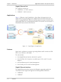
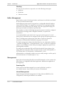
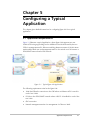
Figure 1-1 illustrates a typical application, where Egate-100 supports two user
VLANs (CPEs using tag stacking) and an additional Host VLAN shared by the two
CPEs for management traffic. Ethernet switching between remotes in VLAN-Aware
mode enables both user and management traffic to be carried over E1s between a
SDH/SONET network and a GbE network.
Figure 1-1. Typical Egate-100 Application
Features
Egate-100 is an Ethernet concentrator grooming Ethernet traffic carried over PDH
(E1/T1) over SDH into a GbE MAN.
The unit includes:
•
One Gigabit Ethernet interface (electrical or optical)
•
One CH-STM-1/OC-3 interface over which up to 63 E1s or 84 T1s can be
mapped
•
One Fast Ethernet port for inband management
•
One Control port for out-of-band management.
Gigabit Ethernet Interface
The Gigabit Ethernet interface operates in full duplex, supporting regular size
(1536 bytes) frames. Egate-100 supports the following Ethernet interfaces:
1-2
•
1000BaseSx
•
1000BaseT
Overview
Egate-100 Installation and Operation Manual
Chapter 1 Introduction
STM-1/OC-3 Interface
Egate-100 supports two CH-STM-1/OC-3 interfaces for SDH mapping (E1s o VC12 o VC4) or SONET mapping (T1s o VT1.5 o STS1 o STS3): either one can be
configured as the active port. The fiber optic interface of the unit uses a singlemode 1310 nm short-haul or long-haul laser diode transmitter, or a multi-mode
1310 nm transceiver.
SDH/SONET mode is user-configurable. Jitter output and tolerance complies with
G.825 requirements.
Ethernet over PDH:
Up to 63 E1s or 84 T1s can be mapped into Egate-100’s CH-STM-1/OC-3
interface: Ethernet over HDLC over E1/T1 (RIC-E1/T1, FCD-E1, FCD-IP
compatible).
Ethernet can be mapped over unframed E1/T1, or over fractional E1/T1. For
fractional E1/T1 – n x 64, where n (number of time slots) = 1-32 for E1 and 1-24
for T1 – up to 128 bundles (associated with up to 128 remote users) are
supported.
Bridging
Egate-100 provides a bridging function between its different bridge ports:
•
Gigabit Ethernet port
•
E1/T1 on SDH/SONET (Ethernet over E1/T1 or fractional E1/T1)
•
Fast Ethernet for management
•
Internal host.
The internal bridge operates in VLAN-Unaware or VLAN-Aware modes (with or
without VLAN double tagging).
The VLAN-Aware bridge mode allows the user to create a subgroup of bridge ports
within the bridge. Each such subgroup is associated with a unique VID. Frames can
be forwarded only between bridge ports that are members of the same VLAN, thus
enabling a total separation between different VLAN users within the same bridge.
In VLAN-Unaware mode the bridge ignores VLAN tags and forwards frames only
according to their source and destination MAC addresses.
Management
Setup, control and monitoring of status and diagnostics information can be
performed using one of the following methods:
• Local and remote management via the Gigabit Ethernet port or the Fast
Ethernet management port
•
Local management via an ASCII terminal connected to the V.24 (RS-232) DCE
control port.
Overview
1-3
Egate-100 Installation and Operation Manual
Chapter 1 Introduction
ConfiguRAD is a user-friendly Web-based element management system for remote
device configuration and maintenance. It is embedded in Egate-100 and provided
at no additional cost. ConfiguRAD can be run from any standard Web browser.
Diagnostics
Egate-100 supports Ping tests and review of self-test results.
Statistics
Egate-100 provides statistics and counter capability at both logical-port and bridgeport levels.
Alarms
Active alarms and log file at the SDH/SONET, GbE, FE and system levels.
Compact Size
E-gate100 is a compact unit, 1U high and half the width of a standard 19” rack. It
can be mounted in a rack or used as a standalone unit.
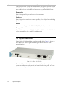
1.2 Physical Description
E-gate100 is a 1U high standalone or rack mountable device. Figure 1-2 shows a
three dimensional view of E-gate100 with Gigabit Ethernet and STM-1/OC-3
network interfaces.
Figure 1-2. Egate-100 3D View
The unit's LEDs, interface and control connectors, and two hot-swappable power
connectors (dual power supply version) are located on the front panel. For more
information see Chapter 2.
1-4
Physical Description
Egate-100 Installation and Operation Manual
Chapter 1 Introduction
1.3 Functional Description
This section describes the major functional features of Egate-100.
Interfaces
SDH/SONET Interface
The SDH/SONET port supports STM-1/OC-3 over optical interface. The optical
interface can be either single mode short haul according to G.957 S 1.1, single
mode long haul according to G.957 L 1.1, or multimode according to ANSI T1
646.
Egate-100 operates in either SONET or SDH mode to support the differences in
framing and mapping parameters.
Two mapping schemes are presented:
•
E1 over STM-1 (SDH path).
•
T1 over OC-3 (SONET path).
STM-1 Mapping
The following figure illustrates the mapping of E1s over SDH.
Figure 1-3. STM-1 / AU-4 / VC-4 / TUG-3s / TUG-2s / TU-12s / VC-12s /E1s
SONET Mapping
The following figure illustrates the mapping of T1s over SONET.
Figure 1-4. Low Order: OC-3 / STS-1 SPEs / VT Group / VT1.5s / T1s
Gigabit Ethernet Interface
The Gigabit Ethernet physical interface is either an optical 1000BaseSx or an
electrical 1000BaseT. The interface supports autonegotiation.
The Gigabit Ethernet interface supports Ethernet and 802.3 standards.
Functional Description
1-5
Egate-100 Installation and Operation Manual
Chapter 1 Introduction
Ethernet Access (Bridge)
Egate-100 has a multi-port bridge with up to two Ethernet bridge ports and up to
128 bridge ports over the CH-STM-1/OC-3 interface. The bridge supports two
modes of operation: VLAN-Aware and VLAN-Unaware.
VLAN-Aware Mode
This mode enables creation of sub-groups of bridge ports within the bridge. Each
sub-group is defined per VLAN and is associated with a unique VID. Frames with
specific VID can be forwarded only between bridge ports that are members of this
specific VLAN, thus enabling a total separation between different VLAN users
within the same bridge.
Bridge Features
•
Full VLAN-Aware bridge as per 802.1q
•
Option for VLAN tag stacking (“double VLAN”) at bridge-port ingress
•
Learning and forwarding according to MAC address and VID
•
Learning of up to 64,000 MAC table entries (MAC-VID pairs)
•
MAC learning limit – can be configured for each bridge port
•
Aging time – can be configured at the bridge level
•
MAC table viewing (learned MACs).
The mechanism of the VLAN-Aware bridge can be described as five different
processes:
•
Ingress – checks each frame entering the bridge to decide if and how this
frame should be passed on to the forwarding process
•
Learning – learns new MAC table entries (MAC only or MAC VID pairs)
•
Aging – checks the forwarding MAC table periodically
•
Forwarding – decides to which bridge port/ports to forward the frame
•
Egress – selects the format of the transmitted frame at the output port, with or
without VLAN.
Ingress Process
The ingress process is composed of three sub-processes: frame admission, ingress
filtering and PVID assignment to untagged/priority only tagged frames.
•
Frame admission – has two modes of operation (configurable per bridge):
Admit all frames – all frames arriving from the port are admitted and
proceed to the Ingress Filtering process.
Admit only VLAN tagged frames – only VLAN-tagged frames are admitted
and allowed to proceed to the ingress filtering process. Untagged or
priority-only tagged frames are discarded.
•
1-6
Ingress filtering – configured per bridge, to one of the following modes:
Functional Description
Egate-100 Installation and Operation Manual
Chapter 1 Introduction
Enabled – perform ingress filtering according to VID. This means that only
frames that share a VID assigned to this bridge port are admitted
Disabled – all frames are forwarded.
Only admitted frames that pass filtering are submitted to the learning and
forwarding processes. Table 1-1 summarizes the behavior of the ingress
process.
Table 1-1. Ingress Process
Frame Admission
Mode
Ingress
Filtering
Mode
Bridge Behavior
Admit all frames
Enabled
VLAN-tagged frames with a VID (or PVID for
untagged/priority tagged frames) that do not
include the bridge port in their VLAN member
set are dropped.
Disabled
All frames pass.
Enabled
VLAN-tagged frames with a VID that do not
include the bridge port in their member set are
dropped. Untagged/priority tagged frames are
dropped.
Disabled
All VLAN-tagged frames pass. Untagged/priority
tagged frames are dropped.
Admit VLAN-tagged
frames
•
PVID assignment – Per bridge port configuration.
In VLAN-Aware mode, each received frame entering the bridge is
associated with a single VID. In case the received frame does not contain
VLAN ID (untagged or priority only tagged frames), a specific PVID is
assigned to these frames before they pass to the forwarding process.
This means that the untagged/priority tagged frames that have passed the
admission are tagged with PVID and proceed to the ingress filtering process.
Tagged frames are double-tagged with the PVID only if Tag Stacking is
enabled.
For untagged frames that were tagged during this process to VID=PVID, a
priority tag of “0” is assigned at the VLAN priority field.
For tagged frames that were double-tagged by PVID (in the case of tagstacking enabled), the VLAN Priority field of the outer VLAN will be copied
from that of the original frame.
Learning Process
The learning process observes the source MAC address (SA) and the VID of the
received frame, and updates the forwarding database with the MAC-VID pair and
with the bridge port that the frame was received from. The Forwarding Data Base
(FDB) is also referred to as the MAC table.
Functional Description
1-7
Egate-100 Installation and Operation Manual
Chapter 1 Introduction
Entries in the MAC table can be dynamic (inserted by the learning process) or static
(inserted by configuration). A dynamic entry has an aging time associated with it.
The Egate-100 VLAN-Aware bridge is an Independent VLAN Learning (IVL) bridge.
The learning process inserts a new dynamic entry to the MAC table. This entry
consists of a MAC-VID pair and bridge port.
•
If the MAC-VID pair already exists for the same port, the aging time is updated
•
If the MAC-VID pair already exists but for a different bridge port (dynamic
entry), the new entry overrides the existing one
•
If the MAC-VID pair already exists for a different bridge port (static entry), the
static entry prevails.
Aging Process
The aging period for a table entry is the time since the last frame for this entry has
entered the bridge.
The aging process checks the forwarding MAC table periodically. Each dynamic
entry for which the aging period has exceeded the configured Aging Time Limit is
deleted. The periodic check of the MAC table (aging time intervals), results in
actual aging time that can reach up to twice the value that was configured by the
user.
Forwarding Process
The forwarding process is performed based on the frame destination MAC-VID
pair. The frame is forwarded to the bridge port that was specified in the MAC table
for this MAC-VID pair entry.
Untagged frames are forwarded according to the PVID that was attached to that
frame during the ingress process.
Frames are forwarded, dropped or flooded according to these guidelines:
•
Forwarded: if the bridge port of the pair entry (DA, VID) in the MAC table is
both an active bridge port and a member of the VLAN, the frame is forwarded
to that bridge port only.
•
Dropped:
Local Filtering: If the bridge port for the pair entry (DA, VID) in the MAC
table is the port on which the frame was received, the frame is dropped.
If there are no active ports associated with the frame’s VID, the frame is
dropped.
•
Flooded:
If the pair (DA, VID) is not learned and does not exist in the MAC table, the
frame is transmitted to all bridge ports that are associated with the frame’s
VLAN ID.
Multicasts and broadcasts are flooded only through the bridge ports whose
VLAN ID is identical to the frame’s VLAN ID.
1-8
Functional Description
Egate-100 Installation and Operation Manual
Chapter 1 Introduction
Egress Process
After the forwarding process identifies the destination bridge port/ports to which
the frame should be transmitted, the transmission process transmits it with the
appropriate format (Egress Tag-handling configuration).
The user can configure per port the frame format to be used at egress:
•
None (Do Not Strip VLAN):
VLAN-tagged frames are transmitted unchanged, or with PVID tag stacking
if this is enabled
Untagged frames are transmitted tagged with priority 0 and VID=PVID of
the port from which they have entered
Priority-tagged frames are transmitted tagged with original priority and
VID = PVID
•
Strip VLAN – in this mode, one level of VLAN is stripped from each frame.
VLAN-Unaware Mode
In this mode the bridge forwarding ignores the VLAN ID of VLAN tagged frames.
Each Ethernet packet received from each bridge port (1GbE, FE or E1s) is
forwarded according to its destination MAC address.
Bridge Features
•
Learning and forwarding according to MAC address only
•
Learning of up to 64,000 MAC addresses
•
MAC learning limit – can be configured for each bridge port
•
Aging time – can be configured at the bridge level
•
VLAN tagged frames transparency (forwarding according to MAC only)
•
MAC table viewing.
Ingress Process
All frames are accepted in this mode: untagged, priority-tagged or VLAN-tagged.
Learning and forwarding is based on the MAC addresses, independent of the
VLAN. This mode is sometimes referred to as transparent mode, due to
“tag transparency”.
Learning Process
The learning process observes the source MAC address (SA) of the received frame
and updates the forwarding database (FDB) with the MAC and the bridge port that
the frame was received from. The FDB is also referred to as the MAC table.
The learning process inserts a new entry into the MAC table. This entry consists of
MAC and bridge port.
•
If the MAC already exists for the same bridge port, the aging time will be
updated
Functional Description
1-9
Egate-100 Installation and Operation Manual
Chapter 1 Introduction
•
If the MAC already exists, but for a different bridge port, (dynamic entry) the
new entry will override the existing one.
Aging Process
The aging process checks the forwarding MAC table periodically. Each dynamic
entry aging time period that has exceeded the configured Aging Time Limit is
deleted. The aging time period is the period of time since the last frame for this
entry has entered the bridge. The periodic check of the MAC table (aging time
intervals), results in an actual aging time that can reach up to twice the value that
was configured by the user.
Forwarding Process
The forwarding process is performed based on the frame MAC Destination
Address (MDA). The frame is forwarded to the Bridge/port specified in the MAC
table for this MAC.
Frames are forwarded, dropped or flooded at this stage for the following reason:
•
Forwarded: A frame will be forwarded according to its DA, to the bridge port
where its DA was learned
•
Dropped: (Local filtering) - If the port for that DA entry in the MAC table is the
port on which the frame was received, the frame will be dropped
•
Flooded:
If there is no information regarding the DA in the MAC table then the frame
is flooded to all ports
Frames with multicast or broadcast address are flooded to all ports.
Egress Process
In this bridge mode (VLAN-Unaware), the frames are transmitted unchanged: No
tags are added or removed.
Quality of Service
Egate-100 supports QoS mapping to up to four strict priority queues at the E1/T1
egress according to one of the following:
•
VLAN priority (available in VLAN-Aware bridge mode only)
•
IP precedence (ToS byte)
•
DSCP (ToS byte)
IP Precedence / DSCP
The IP header is shown in Figure 1-5. TOS byte structure for IP Precedence is
shown in Figure 1-6 and for DSCP in Figure 1-7.
Non-IP frames are mapped to the lowest-priority queue.
1-10
Functional Description
Egate-100 Installation and Operation Manual
0
0
Chapter 1 Introduction
1
1
2
3
4
5
6
7
8
9
0
2
1
2
3
4
5
6
7
8
9
0
3
1
2
3
4
5
6
7
8
9
0
1
IHL
TOTAL LENGTH
TOS
IDENTIFICATION
FLAGS
FRAGMENT OFFSET
TIME TO LIVE
PROTOCOL
HEADER CHECKSUM
SOURCE ADDRESS
DESTINATION ADDRESS
OPTIONS
PADDING
Figure 1-5. IP Header
Bit 0
P2
Bit 1
Bit 2
P1
Bit 3
P0
Bit 4
XX
Bit 5
XX
Bit 6
XX
XX
Bit 7
XX
P2–P0: Precedence value
Figure 1-6. ToS Byte IP Precedence Field
Bit 0
DS5
Bit 1
Bit 2
DS4
Bit 3
DS3
Bit 4
DS2
Bit 5
DS1
Bit 6
DS0
XX
Bit 7
XX
DSCP: six bits (DS5–DS0)
Figure 1-7. ToS Byte DSCP Field
VLAN Priority
VLAN, according to IEEE 802.1p&q, adds four bytes to the MAC layer of the
Ethernet frame. The user can set the contents of these bytes, MAC layer priority
and VLAN ID.
Figure 1-8 shows the VLAN tag format.
user_priority
81
00
8
802.1D Tag Protocol Type
6
Priority
VID
CFI = 0
IP
HEADER
VERSION
5
4
1
8
1
VLAN ID
Figure 1-8. VLAN Tag Format (802.1)
Untagged frames are tagged by the Egate PVID. VLAN priority is set to 0 in this
case, and the frame is mapped accordingly.
In the case of tag stacking, the original VLAN priority is copied to the new VLAN
and the frame is mapped according to this value.
Functional Description
1-11
Egate-100 Installation and Operation Manual
Chapter 1 Introduction
Flooding
The user can choose how to map each one of the following frame types:
•
Multicasts
•
Broadcasts
•
Unknown unicasts.
Buffer Management
Egate-100 has a total of 3050 frame buffers, and frames in each buffer are limited
in size by maximum frame length.
Each bridge port priority queue (at egress) has a configurable threshold. When a
frame enters the bridge, it is assigned for transmission to the appropriate bridge
port based on the functioning of the bridge, and to the appropriate bridge-port
priority queue based on the packet’s priority fields.
If the number of packets in the bridge port priority queue exceeds the configured
threshold, the incoming packet is dropped. Otherwise, it is queued for
transmission.
A second threshold is used at the level of a group of priority queues. For each
priority level, a threshold can be configured for the group of all priority queues (of
the E1/T1 bridge ports) of that priority level. Before a packet is queued for
transmission, both thresholds (individual and group) are checked.
The buffer-management scheme described allows for over-subscription of buffers:
-- Number-of-bridge-ports x Packet-threshold > 3050 – to allow for a high burst
tolerance at the bridge-port level while preventing the high-priority queues from
suffering buffer starvation.
The setting also includes the GbE and FE buffer threshold. Proper design of the
setting will ensure that there will be no buffer starvation for the GbE regardless of
E1/T1 buffer state: E1/T1-threshold + GbE threshold = 3050.
All thresholds are configurable, and the user may modify settings as well as specify
the desired amount of oversubscription, if any.
Management
Egate-100 can be monitored locally from an ASCII terminal, or from a remote site
using Telnet or ConfiguRAD Web based application. RADviewLite application is
also supported.
Event Log File
Events are stored and time-stamped in an event log file that is saved in a
non-volatile memory. Up to 5000 cyclic entries are maintained.
Inband Management
E-gate100 supports inband management via Telnet, Web and RADView-Lite.
Configuration, monitoring and statistics are available.
1-12
Functional Description
Egate-100 Installation and Operation Manual
Chapter 1 Introduction
Out-of-Band Management
Egate-100 enables full configuration and diagnostics via an ASCII terminal. The
ASCII terminal is connected to the Control Port in the Egate-100 front panel.
ASCII terminal activation is provided in Chapter 3 including general instructions for
navigating through the system menus and windows and modifying data.
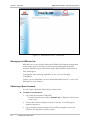
Management Access
E-gate architecture allows access from the GbE network or from the FE
management port to both the E-gate host and remote site devices. In certain
configuration modes, by use of different VLANs a total separation of management
traffic from user traffic can be achieved.
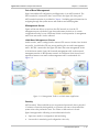
VLAN-Based Management Scheme
In this scenario, traffic coming from the remote CPE uses two VLANs: One VLAN is
user traffic, for which the CPE may use tag stacking; the second is management
traffic. All CPEs connected to the Egate-100 share the same management VLAN.
In VLAN-Aware mode, Egate-100 forwards management traffic to the network
management station in the Ethernet network. As a different VLAN is used, total
separation between user traffic and management traffic is maintained. See
Figure 1-9.
Figure 1-9. Management Traffic in a VLAN-Aware Application
Security
ASCII terminal, Telnet and Web access are password protected. After a period of
15 minutes of inactivity during which no character was sent to the terminal the
system exits to the password screen. The Telnet or Web session is closed.
Egate-100 supports the following access authorization levels:
•
Super-user mode for configuration and monitoring
•
User mode for monitoring and configuration view only.
Functional Description
1-13
Egate-100 Installation and Operation Manual
Chapter 1 Introduction
Statistics and Alarms
Provides statistics and counters capability at the bridge port level.
Active alarms and log file at SDH/SONET, GbE, FE and system level. For more
information, see Chapter 6.
E1/T1 Timing
Egate-100 has a single clock domain and functions as the clock master. All remote
units operate in loopback timing (LBT) mode and use the Egate-100 as their timing
source. The E1/T1 clock source can be driven by an internal oscillator or derived
from the SDH/SONET Rx.
Figure 1-10. E1/T1 Timing
Diagnostics
There are several types of diagnostics and troubleshooting procedures. For more
information see Chapter 6.
•
Ping test and self test
•
Events/Traps
Hierarchically-layered traps/alarms – events resulting from events that were
already reported and are still active – are not sent. For example, LOF event
traps will not be sent if LOS was sent and the physical layer problem persists.
Alarms and traps can be masked, upon user configuration.
1-14
Functional Description
Egate-100 Installation and Operation Manual
Chapter 1 Introduction
1.4 Technical Specifications
Gigabit
Ethernet
Interface
Number of Ports
1
Compatibility
Relevant sections of IEEE 802.3u, 802.3x, 802.1p
and 802.3q
Data Rate
1000 Mbps
Frame Size
Regular (1600 bytes)
Duplex Mode
Full duplex
Interface Connector
1000BaseSx – Optical interface, LC Connector
1000BaseT – Electrical interface, RJ-45 Connector.
Cat. 5 cable
Range
1000BaseSx – 220m/720 ft over 62.5 µm multimode
fiber or 500m/1640 ft over 50 µm multimode fiber
1000BaseT – 100 meters/328 feet on UTP category 5
cables
Fast Ethernet
Management
Interface
STM-1/OC-3
Interface
Wavelength
850 nm
Optical input range
0 to -17 dBm
Optical output
power
0 to -9.5 dBm
Number of Ports
1
Compatibility
Ethernet standards, IEEE 802.3
Data Rate
10/100 Mbps
Frame Size
Regular (1536 bytes)
Electrical Cable Type
Cat. 5 cable
Connector
RJ-45
Range
100 meters/328 feet on UTP category 5 cables
Duplex modes
Full duplex / Half duplex
Autonegotiation
Supported
Number of Ports
1 active, 1 inactive
Connector
LC (SFP)
Data Rate
155 Mbps
Options
Single mode 1310 short haul G.957 S1.1
Single mode 1310 long haul G.957 L1.1
Multimode ANSI T1.646
Range
Long haul: 40 km/25 miles
Technical Specifications
1-15
Egate-100 Installation and Operation Manual
Chapter 1 Introduction
Short haul: 15 km/9.4 miles
Wavelength
1310 nm
Optical input range
Long haul: -10 to -34 dBm
Short haul: -8 to -28 dBm
Internal Bridge
Optical output
power
Long haul: 0 to -5 dBm
Number of Ports
Up to 131 including:
Short haul: -8 to -15 dBm
• Gigabit Ethernet
• Fast Ethernet for management
• Local host
• ETH o E1/T1s o STM-1/OC-3 (up to 128)
Control Port
Monitoring
LAN Table
Up to 64,000 MAC addresses (learned)
Operation Mode
VLAN-Aware, VLAN-Unaware
Buffer
3050 frame buffer
Filtering and
forwarding
Up to 220,000 pps (Full CH-STM-1 capacity)
Interface
RS-232/V.24 (DTE asynchronous)
Data Rate
9.6, 19.2, 38.4, 57.6, 115.2 kbps
Connector
9-pin, D-type, female (DB9)
Statistics
System and physical layer alarms
ETH o E1 frame counters
FE and GbE physical layer alarms and frame counters
Indicators
PWR (green)
On: Egate-100 is powered on
Off: Egate-100 is off
ALM (red)
On: Interface (FE, GbE, SDH/SONET)) or system
alarm exists
Off: No Alarm
ACT (yellow)
Blinking: Ethernet frame received or sent within the
last second
Off: No frame received or sent within the last second
SYNC (green)
On: STM-1 port is synchronized
Off: LOS, LOF
Power
1-16
AC Source
100 to 240 VAC (±10%), 50 to 60 Hz
DC Source
48 VDC
Power Consumption
30W max
Technical Specifications
Egate-100 Installation and Operation Manual
Physical
Environment
Chapter 1 Introduction
Height
43 mm / 1.7 in (1U)
Width
430 mm / 19 in
Depth
240 mm / 9.4 in
Weight
Single power supply: 3.5 kg / 7.7 lb
Dual power supply: 4.0 kg / 8.8 lb
Temperature
0°–50°C / 32°–122°F
Humidity
Up to 90%, non–condensing
Technical Specifications
1-17
Chapter 1 Introduction
1-18
Technical Specifications
Egate-100 Installation and Operation Manual
Chapter 2
Installation and Setup
This chapter includes the following topics:
•
Site requirements and specifications
•
Package contents
•
Equipment needed
•
Installation and setup.
2.1
Introduction
Egate-100 is delivered completely assembled. It is designed for installation as a
desktop unit or for mounting in a 19-inch rack. For rack installation instructions,
refer to the Rack Mounting Kit for 19-inch Racks guide that comes with the RM kit.
After installing the unit, configure Egate-100 using an ASCII terminal connected to
the Egate-100 control port. The Egate-100 configuration procedures are described
in Chapter 3 and Chapter 4.
If problems are encountered, refer to Chapter 6.
Warning
No internal settings, adjustment, maintenance and repairs should be
performed by either the operator or the user. Such activities must be
performed only by skilled personnel who are aware of the hazards involved.
Always observe standard safety precautions during installation, operation and
maintenance of this product.
2.2
Note
Site Requirements and Prerequisites
See also the sections Connection of AC Mains and Connection of DC Mains in the
safety instructions at the beginning of this document.
AC-powered Egate-100 units should be installed within 1.5 meters (5 feet) of an
easily accessible and grounded AC outlet, capable of furnishing the required
supply voltage in the range of 100 to 240 VAC, at 50 or 60 Hz.
DC-powered Egate-100 units should be connected to -48 or -60 VDC mains in
accordance with the DC Connection supplement.
Site Requirements and Prerequisites
2-1
Egate-100 Installation and Operation Manual
Chapter 2 Installation and Setup
Allow at least 90 cm (36 in) of frontal clearance for operator access. For
continuous product operation allow at least 10 cm of frontal clearance, and at
least 15 cm at rear of the unit, for cable connections and ventilation. For proper
ventilation, keep at least 2.5 cm clearance from the sides and top of the product.
The ambient operating temperature of Egate-100 is 0° to 50° C (32° to 122°F), at a
relative humidity of up to 90%, non-condensing.
2.3
Package Contents
The Egate-100 package contains:
•
Egate-100 unit
•
AC power cord
•
DC adapter plug (for DC option)
•
Technical documentation CD
•
RM-34 installation kit (optional).
2.4
Equipment Needed
Hand Tools and Kits
Egate-100 needs no special tools for installation. You need a screwdriver to mount
Egate-100 in a 19-inch rack.
Power Cable
Egate-100 comes equipped with an appropriate (country or region dependent)
power cord to be connected from the power socket on the rear panel to the
mains.
Cable and Connectors
Refer to the following table to determine what cables and connectors are required
for installation. Appendix A specifies the wiring of all connector pinouts.
Table 2-1. Required Connection Media
2-2
Interface
Cable/Connector
Control port
Straight RS-232/V.24 cable with DB-9 female connector
for ASCII terminal
SDH/SONET interface
LC (SFP) fiber optic connection media
Equipment Needed
Egate-100 Installation and Operation Manual
Chapter 2 Installation and Setup
Table 2-1. Required Connection Media (Cont.)
Interface
Cable/Connector
Fast Ethernet interface
RJ-45, 8-pin connection media
GbE interface
Electrical: RJ-45, 8-pin connection media
Optical: LC (SFF) fiberoptic connection media
2.5
Connecting the Interfaces
Connect the Egate-100 network and user interfaces using the ports on the front
panel.
Refer to Appendix A for all connector pinouts.
Connecting the SDH/SONET Port
The Egate-100 SDH/SONET network port terminates in a fiber optic interface with
LC connectors (SDH/SONET).
To connect the SDH/SONET interface:
•
Connect the SDH/SONET equipment to the fiber optic front panel
connectors.
Connecting the GbE Port
The Egate-100 GbE interface terminates with an 8-pin RJ-45 (electrical) or LC
(optical) connector.
To connect the GbE interface:
•
Connect the GbE equipment to the relevant connector on the front panel:
•
Electrical: Connect using the RJ-45, 8-pin connector.
•
Optical: Connect using the fiber optic LC (SFF) front panel connectors.
Connecting the Fast Ethernet Port
The Egate-100 user Fast Ethernet interface terminates in an 8-pin RJ-45 connector.
To connect the Fast Ethernet interface:
•
Connect the 100BaseT cable to the ETH-MNG RJ-45 front panel connector.
Connecting the Terminal
To connect the terminal:
Use a straight cable to connect the control terminal to the front panel 9-pin
CONTROL connector,
– or –
Connecting the Interfaces
2-3
Chapter 2 Installation and Setup
Egate-100 Installation and Operation Manual
Connect the CONTROL port to an ASCII terminal using a straight RS-232 cable.
2.6
Connecting the Power
Egate-100 can be ordered with either AC power or DC power (for more
information, refer to the Egate-100 data sheet).
Connecting the AC Power
AC power is supplied to Egate-100 via a standard 3-prong plug with an integral
fuse holder.
AC power should be supplied through the 1.5m (5 ft) standard power cable
terminated by a 3-prong plug. The cable is provided with the unit.
Warning
Before switching on this unit and connecting or disconnecting any other cable,
the protective earth terminals of this unit must be connected to the protective
ground conductor of the mains power cord. If you are using an extension cord
(power cable) make sure it is grounded as well.
Any interruption of the protective (grounding) conductor (inside or outside the
instrument) or disconnecting of the protective earth terminal can make this
unit dangerous. Intentional interruption is prohibited.
If the Egate-100 unit is equipped with two hot-swappable power supplies,
DO NOT install AC and DC power supplies together in the same unit.
To connect AC power:
1. Connect the power cable to the power connector on the Egate-100 front
panel.
2. Connect the power cable to mains outlet.
The unit turns on automatically upon connection to the mains.
Connecting the DC Power
To connect DC power:
•
2-4
Refer to the DC power supply connection supplement, located on the
Technical Documentation CD, and the safety instructions at the beginning of
this document.
Connecting the Power
Chapter 3
Operation
This chapter:
•
Explains power-on and power-off procedures
•
Provides a detailed description of the front panel controls and indicators and
their functions
•
Provides instructions for using a terminal connected to the Egate-100 control
port
•
Describes how to navigate menus
•
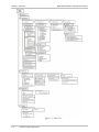
Illustrates the management menu tree.
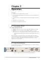
3.1 Turning Egate-100 On
To turn on the Egate-100 unit:
•
AC unit: Connect the unit to AC mains using a RAD-supplied power cable.
•
DC unit: Use the circuit breaker in the building installation to turn the
Egate-100 unit on, connecting the terminals on the DC plug to the DC mains.
The PWR indicator lights up and remains lit as long as Egate-100 receives
power.
Egate-100 requires no operator attention once installed, with the exception of
occasional monitoring of the front panel indicators. Intervention is only required
when the unit must be configured to its operational requirements, or when
diagnostic tests are performed.
3.2 Controls and Indicators
The unit's LEDs are located on the front panel (see Figure 3-1). Table 3-1 lists the
functions of the LED indicators.
Figure 3-1. Egate-100 Front Panel (Dual Power Supply Version)
Controls and Indicators
3-1
Egate-100 Installation and Operation Manual
Chapter 3 Operation
Table 3-1. Egate-100 LEDs and Controls
Name
Color
Function
PWR (single power
supply version)
Green
On: Egate-100 is powered on
Off: Egate-100 is off
RDY
Green
On: Self test has been completed
successfully
Blinking: Self test has failed
ALM
Red
On: Interface (FE, GbE, SDH/SONET) or
system alarm exists
Off: No Alarm
LINK (FE)
Green
On: Ethernet connection is up
Off: Ethernet connection is down
Yellow
Blinking: Ethernet frame was received or
sent within the last second
Green
On: STM-1 port is synchronized
Off: LOS, LOF
PS1 / PS2 (dual power
supply version)
LINK (GbE)
ACT (FE)
ACT (GbE)
SYNC 1
SYNC 2
3.3 Default Settings
Table 3-2 lists the default settings of the Egate-100 configuration parameters.
Table 3-2. Default Settings
3-2
Component
Parameter
Default Value
System
Device Name
EGATE100
Location
The Location of this Device
Contact Person
Name of Contact Person
Host IP address
0.0.0.0
Host IP mask
0.0.0.0
Host default gateway
0.0.0.0
Read community
Public
Write community
(null)
Trap community
(null)
Host Tagging
Untagged
Host VLAN ID
1
Host Priority Tag
0
Default Settings
Egate-100 Installation and Operation Manual
Chapter 3 Operation
Table 3-2. Default Settings (Cont.)
Component
Parameter
Default Value
Baud rate
115,200 bps
Master Clock Source
Rx Clock (SONET/SDH Rx)
Fallback Clock
Source
Rx Clock (SONET/SDH Rx)
Max Buffers
100
Activity
Up
Alarm
Unmasked
Frame type
SDH
Tx clock
Loopback Timing
SOH Alarms
Unmasked
HVC Alarms
Unmasked
LVC Alarms
Unmasked
APS
Port 1
STM-1 Mapping
Activation
Enabled
E1/T1 Frame Type
Unframed
E1/T1 Idle Code
0
E1/T1 Alarms
Unmasked
Activity
Up
Alarm
Unmasked
Autonegotiation
Enabled
Activity
Up
Alarm
Unmasked
Autonegotiation
Enabled
Speed
100BaseT
Mode
Full-duplex
Logical Ports
Type
HDLC
Bridge
VLAN-Mode
VLAN-Unaware
Aging Time
300
Activation
Enabled
Ingress Filtering
Disabled
Accept Frame Type
All
Port VID
1
SDH/SONET Port
GbE Port
Fast Ethernet Port
Bridge Ports
Default Settings
3-3
Egate-100 Installation and Operation Manual
Chapter 3 Operation
Table 3-2. Default Settings (Cont.)
Component
Parameter
Default Value
Egress Tag Handling
None
Ingress Tag Handling
None
Maximum Learning
MAC Address
64000
3.4 Configuration Alternatives
Configuration and monitoring operations are performed locally from an ASCII
terminal connected to the control port or from a PC running a Web browser,
Telnet, or RADview-Lite over the GbE network or via the FE MNG port.
The SU account has permission to view and to change all configuration
parameters. The User account has permission only to view parameters.
The following functions are supported by the Egate-100 management software:
•
Viewing system information
•
Modifying configuration and mode of operation, including setting system
default values and resetting the unit
•
Monitoring Egate-100 performance
•
Upgrading software.
Managing via the Terminal Port
Egate-100 includes a V.24/RS-232 asynchronous DCE port, designated CONTROL
and terminated in a 9-pin D-type female connector. The control port continuously
monitors the incoming data stream and immediately responds to any input string
received through this port.
The Egate-100 control port can be configured to communicate at the following
rates: 9.6, 19.2, 38.4, 57.6 or 115.2 kbps.
To start a terminal control session:
1. Make sure all Egate-100 cables and connectors are properly connected.
2. Connect Egate-100 to a PC equipped with an ASCII terminal emulation
application (for example, Windows Hyper Terminal or Procomm).
3. Turn on the control terminal PC and set its default port parameters to
19,200 baud, 8 bits/character, 1 stop bit, no parity, no flow control.
4. Set the terminal emulator to ANSI VT100 emulation (for optimal view of
system menus).
5. Press any key to display the login screen.
3-4
Configuration Alternatives
Egate-100 Installation and Operation Manual
Chapter 3 Operation
Logging In via an ASCII Terminal
To log in via an ASCII terminal:
1. Enter SU as the user name. SU (super user) has full read/write permissions.
2. Enter 1234 for (default) password.
Note
It is recommended to change default passwords to prevent unauthorized access to
the unit.
Choosing Terminal Options
To choose an option:
1. Type the number corresponding to the option, and press <Enter>.
2. When any change is made in the menu, the Save option appears as the last
option in the menu.
3. Type the number corresponding to the Save option in the current menu, and
press <Enter> to save your change.
Egate-100 updates its database with a new value or displays a new menu
for the selected option.
4. If you press <ESC> to exit the menu without saving your changes, the
following message appears:
“Do you want to save changes (Y/N/C)?”
Type the appropriate letter to save or not save your changes
(Yes/No/Cancel).
Navigating Terminal Tables
Some of the Egate-100 management software screens are tables, which are larger
than standard menus and require scrolling to navigate between parameters.
Use the following keys (case-sensitive) for table navigation:
•
<Ctrl>+L – scroll left
•
<Ctrl>+R – scroll right
•
<Ctrl>+U – scroll up
•
<Ctrl>+D – scroll down
•
Right/Left Arrows – move right/left (editable tables only)
•
Up/Down Arrows – move up/down (editable tables only)
•
<Tab> – select next editable cell
•
G<row number>,<col number> – go to a specific cell
•
<Ctrl>+G – go to top of table (log file, MAC table)
Configuration Alternatives
3-5
Egate-100 Installation and Operation Manual
Chapter 3 Operation
Note
You can display these navigation keys by typing <?> from a table.
Managing via ConfiguRAD
ConfiguRAD is a Web-based remote access terminal management software. It
provides a user-friendly interface for configuring, collecting statistics and
monitoring the Egate-100 unit.
Web Browser Requirements
The following Web browsers can be used to access Egate-100 ConfiguRAD
supervision utility from any location using Internet protocols.
•
Internet Explorer 6.0, running on Windows™ 98, Windows™ 2000 or
Windows™ XP
•
Netscape Communicator 7.1, running on Windows™ NT or Unix.
Figure 3-2. Web Browser Access – Login Window
Logging In via ConfiguRAD
To login via Web browser:
1. Connect the Ethernet port of Egate-100 to the LAN.
2. Open the Web browser.
3. Disable any pop-up blocking software, such as Google Popup Blocker.
4. Enter the IP address of the Egate-100 in the address field of the browser in the
following format: http://IP address and then press <Enter> to command the
browser to connect (IP address stands for the actual Egate-100 IP address
which has to be assigned via an ASCII terminal).
3-6
Configuration Alternatives
Egate-100 Installation and Operation Manual
Chapter 3 Operation
5. After the opening window is displayed, click LOGIN.
6. In the Login window (Figure 3-2), enter your user name (read/write user
default is SU) and password (default is 1234).
The ConfiguRAD Main Menu for Egate-100 is displayed (Figure 3-3).
Note
• It is recommended to change default passwords to prevent unauthorized access
to the unit.
• Egate-100 allows up to six management sessions to be active at a time. This
includes up to five network sessions (Telnet, Terminal, ConfiguRAD, RADviewLite) and one ASCII terminal session.
• If no user input is detected for 15 minutes during a ConfiguRAD session,
Egate-100 automatically disconnects from the management station.
Navigating the ConfiguRAD Menus
At the left-hand bottom corner, ConfiguRAD provides some auxiliary management
tools:
•
Status – shows the number of users currently managing Egate-100.
•
Trace – opens an additional pane for system messages, progress indicators
(ping, software and configuration file downloads) and alarms. It is
recommended to keep the trace pane open all the time.
•
Refresh All – refreshes performance registers.
To choose an option:
1. Click a link in the ConfiguRAD screen to display the next menu.
2. Once the target screen is displayed, select a value from the drop-down box or
enter it in a text box.
Configuration Alternatives
3-7
Egate-100 Installation and Operation Manual
Chapter 3 Operation
Figure 3-3. Web Browser Access – Main Menu
Managing via RADview-Lite
RADview-Lite is a user-friendly and powerful SNMP-based element management
system (EMS), used for planning, provisioning and managing heterogeneous
networks. RADview-Lite provides monitoring of RAD products and networks via
their SNMP agents.
Configuration and monitoring capabilities are via a GUI-cut-through to
ConfiguRAD.
Contact your local distributor for more details about RADview-Lite, or refer to the
RADview-Lite User's Manual.
Obtaining a New Password
If a user forgets a password, follow the procedure below.
To obtain a new password:
1. Log in with the username CHNGPASS.
A random identification number (Dynamic Key) is displayed at the bottom
of the screen.
2. Contact RAD Technical Support and refer to this key. You will be given a
temporary password.
3. Log in using the temporary password. You will be prompted to enter and
confirm a new password for future sessions.
3-8
Configuration Alternatives
Egate-100 Installation and Operation Manual
Chapter 3 Operation
3.5 Overview of Menu Operations
Egate-100’s management software includes tools for configuring, operating and
monitoring the system. The Main Menu options (see Figure 3-4) are:
•
Inventory – displays information on the functional blocks of the unit
•
Configuration – defines parameters for the Egate-100 system, physical layer
(SDH/SONET, GbE and FE ports), bridge and quality of service.
•
Monitoring – displays port connection status; a log file; active alarms; Ethernet
status and physical characteristics; bridge port statistics; and a MAC table for
running applications.
•
Diagnostics – initiates diagnostic tests – ping and displaying self-test results.
•
Utilities – manages transfer of updates to/from a remote server: upload of
software and download/upload of the configuration file.
You can use this menu tree as a reference aid when performing configuration and
control functions.
EGATE-100
Main Menu
1. Inventory
>
2. Configuration
>
3. Monitoring
>
4. Diagnostics
>
5. Utilities
>
Please select item <1 to 5>
ESC-prev.menu; !-main menu; &-exit
Figure 3-4. Egate-100 Main Menu
Overview of Menu Operations
3-9
Chapter 3 Operation
Egate-100 Installation and Operation Manual
Figure 3-5. Menu Tree
3-10
Overview of Menu Operations
Egate-100 Installation and Operation Manual
Chapter 3 Operation
3.6 Turning Egate-100 Off
To power off the Egate-100 unit:
•
Remove the power cord from the power source.
Turning Egate-100 Off
3-11
Chapter 3 Operation
3-12
Turning Egate-100 Off
Egate-100 Installation and Operation Manual
Chapter 4
Configuration
This chapter explains the Egate-100 configuration, utility and inventory screens
and provides guidance on the parameter options. Although examples are given
from a terminal screen, the information is relevant for Telnet and ConfiguRAD as
well, as their menus are the same as those of the terminal.
The following three Main Menu options are presented in this chapter:
•
Inventory – displays information on the functional blocks of the unit (see
Section 4.7)
•
Configuration – defines parameters for the Egate-100 system, physical layer
bridge and quality of service (see Section 4.1)
•
Utilities – manages transfer of software updates from a remote server: upload
of software and download/upload of the configuration file (see Section 4.8).
The complete menu tree of Egate-100’s management software is shown in
Chapter 3. Monitoring and diagnostics menus are presented in Chapter 6.
4.1 Configuration Sequence
The configuration procedure for Egate-100 includes the following stages:
1. Defining system parameters (IP and terminal access settings) (see Section 4.2)
2. Configuring the physical layer (SDH/SONET, GbE and FE ports) (see Section
4.3)
3. Configuring the logical layer (see Section 4.4)
4. Configuring the internal bridge (see Section 4.5) and Quality of Service (see
Section 4.6).
Egate-100 must be defined by the user at each stage, as many of the parameters
do not have default settings. If a parameter is not defined correctly, an error
message appears.
4.2 Defining System Parameters
The Egate-100 management software allows you to do the following via the System
menu (see Figure 4-1):
• Select the system master and fallback clock sources
•
Configure the management environment, including:
Defining System Parameters
4-1
Egate-100 Installation and Operation Manual
Chapter 4 Configuration
Assign a name and give a description for the device, and enter information
regarding device location and a contact person
Define IP parameters of the Egate-100 host (network management station)
Configure management access
Control user access
•
Configure terminal baud rate
•
Mask or unmask the system alarms
•
Set the internal system data and time
•
Reset Egate-100 to factory default settings (see Section 4.9)
•
Define buffer management thresholds.
EGATE-100
Main Menu>Configuration>System
1. Clock Source
>
2. Management
>
3. Control Port
>
4. Alarms
>
5. Date and Time
>
6. Factory Default
7. Buffer Management
>
Please select item <1 to 7>
ESC-prev.menu; !-main menu; &-exit
Figure 4-1. System Menu
Selecting the Clock Source
Egate-100’s system clock is used for E1/T1 tributary timing. Egate-100 is assigned a
master system clock, and a fallback clock that goes into action in case the master
clock fails (e.g. when the link supplying the timing fails).
The master and fallback clock can be assigned as the internal clock of the
Egate-100 unit, or as the SDH/SONET (active link) Rx clock. It is recommended to
have different settings for the master clock and fallback clock: for example,
SDH/SONET for the master clock and Internal for the fallback clock.
In the event that both Master and Fallback clocks (set to Rx) fail, the system clock
is automatically set to Internal.
To select the Clock Source:
1. Follow the path: Main Menu > Configuration > System > Clock Source
The Clock Source menu appears:
4-2
Defining System Parameters
Egate-100 Installation and Operation Manual
Chapter 4 Configuration
EGATE-100
Main Menu>Configuration>System>Clock Source
1. Master Clock
>
2. Fallback Clock
>
Please select item <1 to 2>
ESC-prev.menu; !-main menu; &-exit
Figure 4-2. Clock Source Menu
2. From the Clock Source menu, select Master Clock.
The Master Clock menu appears:
Main Menu>Configuration>System>Clock Source>Master Clock
1. Source
>
(Rx Clock)
2. Wait to Restore (sec)[0 - 720]
Port
>
(SDH/SONET)
Please select item <1 to 2>
ESC-prev.menu; !-main menu; &-exit
Figure 4-3. Master Clock Menu
3. Choose one of the following to indicate the first-priority source of timing for
the Egate-100:
Internal, if you want the master clock to be the internal clock of the
Egate-100 unit.
Rx Clock, if you want the master clock source to be the Rx clock from the
SDH/SONET active link. This is the default value.
4. If you choose Rx Clock, enter a Wait to Restore value: the number of seconds
(between 0 and 720) to wait before an attempt for the Master clock to be
restored.
5. Select Save.
6. From the Clock Source menu, select Fallback Clock.
The Fallback Clock menu appears (see Figure 4-4).
EGATE-100
Main Menu>Configuration>System>Clock Source>Fallback Clock
1. Source
>
(Internal)
Please select item <1 to 1>
ESC-prev.menu; !-main menu; &-exit
Figure 4-4. Fallback Clock Menu
Defining System Parameters
4-3
Egate-100 Installation and Operation Manual
Chapter 4 Configuration
7. Choose one of the following, to indicate the second-priority source of timing:
Internal, if you want the fallback clock to be the internal clock of the
Egate-100 unit.
Rx CLock, if you want to set the fallback clock as the Rx clock from the
SDH/SONET active link. This is the default value.
8. If you choose Rx Clock, enter a Wait to Restore value (between 0 and 720
seconds).
9. Select Save.
Note
It is not recommended to set both the Master and the Fallback clock sources to the
same Rx clock.
Entering Device Information
The Egate-100 management software allows you to assign a name to the unit, and
specify its location to distinguish it from the other devices installed in your
organization. A contact person can also be assigned. Each of these fields can hold
up to 50 characters.
To enter device information:
1. Follow the path: Main Menu > Configuration > System >Management >
Device Information
The Device Info menu appears (see Figure 4-5).
2. From the Device Info menu, select Device Name and enter a desired name
for the Egate-100 unit. The default name is EGATE100.
3. Select Location, and enter a description of the Egate-100’s current location.
4. Select Contact Person, and enter the name of a contact person for this unit.
5. Select Save.
EGATE-100
Main Menu>Configuration>System>Management>Device Information
Description
... (EGATE100 HW Version:0.00/A, SW Version:1.00)
1. Name
... (EGATE100)
2. Location
... (The location of this device)
3. Contact
... (Name of contact person)
Please select item <1 to 3>
ESC-prev.menu; !-main menu; &-exit
Figure 4-5. Device Information Menu
4-4
Defining System Parameters
Egate-100 Installation and Operation Manual
Chapter 4 Configuration
Configuring IP Host Parameters
Egate-100 can be managed by a network management station connected to the
unit’s Fast Ethernet port, or via the 1GbE network. In order to establish a proper
connection, it is necessary to configure the following: Host IP address, subnet
mask, default gateway, its trap, read and write communities. In addition, by
selecting forwarding mode and VLAN parameters, it is possible to create a separate
management VLAN.
To define the IP parameters:
1. From the Management menu, select Host.
The Host menu appears:
EGATE-100
Main Menu>Configuration>System>Management>Host
1. IP Address
... (0.0.0.0)
2. IP Mask
... (0.0.0.0)
3. Default Gateway
... (0.0.0.0)
4. Read Community
... (public)
5. Write Community
... ()
6. Trap Community
... ()
7. Encapsulation
>
Please select item <1 to 7>
ESC-prev.menu; !-main menu; &-exit
Figure 4-6. Host Menu
2. From the Host menu, perform the following (refer to Table 4-1):
Select IP Address to define the IP address of the host.
Select IP Mask to define the host IP subnet mask.
Select Default Gateway and set the default gateway IP address to that of
the host IP subnet.
Select Read Community to enter the name of a community with ReadOnly authorization.
Select Write Community to enter the name of a community with Write
authorization.
Select Trap Community to enter the name of a community to which
Egate-100 should send traps.
Table 4-1. Host Parameters
Parameter
Possible Values
Remarks
IP Address
0.0.0.0 to
255.255.255.255
Host IP address
IP Mask
0.0.0.0 to
255.255.255.255
Host IP subnet mask
Default: 0.0.0.0
Default: 0.0.0.0
Defining System Parameters
4-5
Egate-100 Installation and Operation Manual
Chapter 4 Configuration
Table 4-1. Host Parameters (Cont.)
Parameter
Possible Values
Remarks
Default
Gateway
0.0.0.0 to
255.255.255.255
Default gateway IP address : Should be
set to that of the host IP subnet
Default: 0.0.0.0
Read
Community
public
Write
Community
public
Trap
Community
public
Default: public
private
Default: (none)
private
Default: (none)
private
3. Select Encapsulation to define VLAN tagging performed by the host
The Encapsulation menu appears:
EGATE-100
Main Menu>Configuration>System>Management>Host>Encapsulation
1. Host Tagging
>
(Tagged)
2. Host VLAN ID[1 - 4094]
... (1)
3. Host Priority Tag[0 - 7]
... (0)
Please select item <1 to 3>
ESC-prev.menu; !-main menu; &-exit
Figure 4-7. Encapsulation Menu
4. From the Encapsulation Menu, perform the following (refer to Table 4-2):
Select the Host Tagging mode: Tagged or Untagged.
Select Host VLAN ID to specify the host VLAN ID (1–4094).
Displayed only when Tagged mode is selected for Host Tagging.
Select Host Priority Tag to specify the priority level for the host VLAN (0–
7).
Displayed only when Tagged mode is selected for Host Tagging.
5. Select Save.
6. Return to the Host IP menu and save again.
4-6
Defining System Parameters
Egate-100 Installation and Operation Manual
Chapter 4 Configuration
Table 4-2. Host Encapsulation Parameters
Parameter
Possible Values
Remarks
Host Tagging
Untagged
Tagged
Untagged: The host transmits and receives
only untagged frames. In VLAN-Aware mode,
the host bridge port must be set to Stripping.
Tagged: The host transmits VLAN-tagged
frames and receives only frames tagged with
the same VLAN ID as that of the host.
Default: Untagged
Host VLAN ID
1–4094
Sets the VLAN ID of the packets sent by the
host. (Displayed only when Host Tagging is
set to Tagged.)
Default: 1
Host Priority Tag
0–7
Quality of Service priority tag for packets sent
by the host. (Displayed only when Host
Tagging is set to Tagged.)
Default: 0
Configuring the Network Managers
Define or modify the network management stations to which the SNMP agent of
Egate-100 sends traps. Up to 16 managers can be defined. The IP address defines
each management station. In addition, you can temporarily prevent a manager
station from receiving traps by masking the network manager.
To add a network manager:
1. From the Management menu, select Managers List.
The Managers List menu appears (see Figure 4-8).
2. Enter a sequential number, corresponding to the manager you wish to specify.
3. Specify IP Address and Trap (masked/unmasked).
To edit the managers list:
1. From the Management menu, select Managers List.
The Managers List menu appears (see Figure 4-8).
Defining System Parameters
4-7
Egate-100 Installation and Operation Manual
Chapter 4 Configuration
EGATE-100
Main Menu>Configuration>System>Management>Managers List
Num
IP address
Trap
1
0.0.0.0
Unmask
2
0.0.0.0
Unmask
|
3
0.0.0.0
Unmask
v
4
0.0.0.0
Unmask
5
0.0.0.0
Unmask
6
0.0.0.0
Unmask
7
0.0.0.0
Unmask
1. Change cell
... (0.0.0.0)
Please select item <1 to 1>
C - Clear
ESC-prev.menu; !-main menu; &-exit; ?-help
Figure 4-8. Managers List Menu
2. From the Managers List menu, move the cursor to the Manager IP cell you
wish to change by pressing <Tab>.
The selected cell is highlighted and the value is displayed in the Change
cell field.
3. Select Change cell, and enter a new IP address for the selected network
manager.
4. Move the cursor to the Trap field and toggle between Mask and Unmask to
mask or unmask traps for the selected management station.
Controlling User Access
From the User Access menu you can change the current user’s password. Egate100 supports only two user names (SU and User). The unit is supplied with the
following default user settings:
•
Superuser name – SU, Password – 1234.
•
User name – User, Password: 1234.
The SU account has permission to view and to change all configuration
parameters. The User account has permission only to view parameters.
To change the current user name and password:
1. Follow the path: Main Menu>Configuration>System>Management>User
Access>Change Password.
The Change Password screen is displayed (see Figure 4-9).
2. From the Change Password screen, confirm that the current user name is
displayed: User or SU.
3. Select Password, and enter the current password (default is 1234).
4-8
Defining System Parameters
Egate-100 Installation and Operation Manual
Chapter 4 Configuration
4. Select New Password and assign a new password of up to eight characters to
the current user.
The password is case sensitive.
5. Select Confirm new Password to confirm the new password.
If the new password and confirmation do not match then an Illegal confirm
password error message is displayed.
Reassign the new password.
6. Select Save.
EGATE-100
Configuration>System>Management>User Access>Change Password
1. User Name
... (USER)
2. Password
... (********)
3. New Password
... (********)
4. Confirm new Password
... (********)
5. Save
> Please select item from 1 to 5
ESC-Previous menu; !-Main menu; &-Exit
1 user(s)
Figure 4-9. Change Password Menu
To view users with permission to access the system:
•
Follow the path: Main Menu>Configuration>System>Management>User
Access>User info
The User Info table appears (see Figure 4-10). It shows users with
permission to access Egate-100 and their access level (Read Only or
Read/Write). Note that the device supports only permanent accounts.
EGATE-100
Main Menu>Configuration>System>Management>User Access>User Info
User Name
Access level
Dynamic/Permanent
1
USER
RO
Permanent
2
SU
RW
Permanent
ESC-prev.menu; !-main menu; &-exit; ?-help
Figure 4-10. User Info Table
Defining System Parameters
4-9
Egate-100 Installation and Operation Manual
Chapter 4 Configuration
Configuring Terminal Parameters
Egate-100 allows you to configure the terminal baud rate.
Note
The Baud Rate parameter is masked during a Telnet or Web-based session, as the
baud rate is used for the session communication.
To change the terminal baud rate:
1. Follow the path: Main Menu > Configuration > System >Control Port.
The Control Port menu appears:
EGATE-100
Main Menu>Configuration>System>Control Port
1. Baud Rate
>
(19200 bps)
Please select item <1 to 1>
ESC-prev.menu; !-main menu; &-exit
Figure 4-11. Control Port Menu
2. From the Control Port menu, select Baud Rate.
The Baud Rate menu appears.
3. Select the desired baud rate (9600, 19200, 38400, 57600, 115200). The default
baud rate is 115200.
Table 4-3. Terminal Parameters
Parameter
Possible Values
Remarks
Baude Rate
9600 bps
Communication speed
19200 bps
Default: 19200
38400 bps
57600 bps
115200 bps
Configuring Alarm Masking
To mask/unmask system alarms:
1. Follow the path: Main Menu > Configuration > System > Alarms
The Alarms configuration screen appears (see Figure 4-12).
2. Configure system alarms: Masked or Unmasked. (By default they are
Unmasked.)
4-10
Defining System Parameters
Egate-100 Installation and Operation Manual
Chapter 4 Configuration
EGATE-100
Main Menu>Configuration>System>Alarms
1. Alarms
> (Unmasked)
ESC-prev.menu; !-main menu; &-exit
Figure 4-12. Alarm Configuration Screen
Entering Date and Time
To enter date and time information:
1. Follow the path: Main Menu > Configuration > System > Date and Time
The Date and Time screen appears (see Figure 4-13).
2. Select Date to update the date in the format illustrated.
3. Select Time to update the time in the format illustrated.
EGATE-100
Main Menu>Configuration>System>Date and Time
1. Date
[YYYY-MM-DD]
2. Time [HH:MM:SS]
... (2005-03-31)
... (13:14:15)
Please select item <1 to 2>
ESC-prev.menu; !-main menu; &-exit
Figure 4-13. Date and Time Screen
Entering Buffer Management Information
Buffers are used to hold frames in the event of a burst of traffic. Egate-100’s
management software allows you to customize Egress drop thresholds (maximum
burst supported) for individual logical port queues – each of four priority levels –
and for the total of all logical-port queues of each priority level. Drop thresholds
can also be specified for the GbE, Fast Ethernet (ETH 1) and Host ports. See
Chapter 1 for additional information.
To configure buffer management:
1. Follow the path: Main Menu > Configuration > System > Buffer
Management
The Buffer Management menu appears (see Figure 4-14).
2. From the Buffer Management menu, select a logical-port priority level (for
example, Traffic Class 1 Max) and specify the maximum number of buffers
allowed for each logical-port queue at this Quality-of-Service priority level.
3. Repeat the previous step for any additional priority levels you wish to
customize at the individual queue level (Max).
Defining System Parameters
4-11
Egate-100 Installation and Operation Manual
Chapter 4 Configuration
4. From the Buffer Management menu, select a logical-port priority level (for
example, Traffic Class 1 Total) and specify the total maximum number of
buffers for all logical port queues at this Quality-of-Service priority level.
5. Repeat the previous step for any additional priority levels you wish to
customize at the queue group level (Total).
6. Select GbE Max to change the maximum number of buffers for the GbE port.
7. Select ETH 1 Max to change the maximum number of buffers for the Fast
Ethernet port.
8. Select HOST Max to change the maximum number of buffers for host
management.
To reset buffer management parameters:
1. Follow the path: Main Menu > Configuration > System > Buffer
Management
The Buffer Management menu appears (see Figure 4-14).
2. From the Buffer Management menu, select Set to Default.
The default configuration is restored.
EGATE-100
Configuration>System>Buffer Management
1. Traffic Class 0 Max[1 - 3000]
... (100)
2. Traffic Class 1 Max[1 - 3000]
... (100)
3. Traffic Class 2 Max[1 - 3000]
... (100)
4. Traffic Class 3 Max[1 - 3000]
... (100)
5. Traffic Class 0 Total[1 - 3000]... (600)
6. Traffic Class 1 Total[1 - 3000]... (600)
7. Traffic Class 2 Total[1 - 3000]... (600)
8. Traffic Class 3 Total[1 - 3000]... (2500)
9. GbE Max [1 - 3000]
... (50)
10. ETH 1 Max[1 - 3000]
... (100)
11. HOST Max[1 - 3000]
... (100)
12. Set To Default
>
Please select item <1 to 12>
ESC-prev.menu; !-main menu; &-exit
1 M/ 1 C
-----------------------------------------------------------------------------
Figure 4-14. Buffer Management Menu
4-12
Defining System Parameters
Egate-100 Installation and Operation Manual
Chapter 4 Configuration
Table 4-4 Buffer Management Parameters
Parameter
Possible Values
Remarks
Traffic Class 0
Max
1–3000
Maximum burst supported for a bridge port
priority queue of traffic class 0
Default: 100
Traffic Class 1
Max
1–3000
Maximum burst supported for a bridge port
priority queue of traffic class 1
Default: 100
Traffic Class 2
Max
1–3000
Maximum burst supported for a bridge port
priority queue of traffic class 2
Default: 100
Traffic Class 3
Max
1–3000
Maximum burst supported for a bridge port
priority queue of traffic class 3
Default: 100
Traffic Class 0
Total
1–3000
Total burst supported for all bridge port
priority queues of traffic class 0
Default: 600
Traffic Class 1
Total
1–3000
Total burst supported for all bridge port
priority queues of traffic class 1
Default: 600
Traffic Class 2
Total
1–3000
Total burst supported for all bridge port
priority queues of traffic class 2
Default: 600
Traffic Class 3
Total
1–3000
GbE Max
Buffers
1–3000
ETH 1Max
Buffers
1–3000
Total burst supported for all bridge port
priority queues of traffic class 3
Default: 2500
Maximum burst supported for GbE port
Default: 50
Maximum burst supported for Fast Ethernet
port
Default: 100
HOST Max
Buffers
1–3000
Maximum burst supported for Fast Ethernet
port
Default: 100
Set to Default
Restores the default buffer mangement
configuration.
Defining System Parameters
4-13
Egate-100 Installation and Operation Manual
Chapter 4 Configuration
4.3 Configuring Ports at the Physical Level
Egate-100 has SDH/SONET, GbE and Fast Ethernet ports. The SDH/SONET, GbE
and Fast Ethernet configuration menus are accessed from the Physical Ports menu.
If you need to make a change to the configuration of SDH/SONET physical ports,
you must first clear any mapping of these ports to the logical ports.
Configuring the SDH/SONET Port
To configure SDH/SONET ports:
1. Follow the path: Main Menu > Configuration > Physical Ports.
The Physical Ports menu appears:
EGATE-100
Main Menu>Configuration>Physical Ports
1. SDH/SONET
>
2. 1GbE
>
3. Fast Ethernet
>
Please select item <1 to 3>
ESC-prev.menu; !-main menu; &-exit
Figure 4-15. Physical Ports Menu
2. From the Physical Ports menu, select SDH/SONET.
The SDH/SONET menu appears (see Figure 4-16).
3. Configure SDH/SONET Frame type and Tx CLock. (See Table 4-5 for details)
4. Configure SDH/SONET APS (setting Port 1 or Port 2 as the in-force port).
5. Configure Activation and Alarms (see below).
6. Configure STM-1 Mapping (see below).
7. Configure SOH, HVC and LVC Alarms (see below).
4-14
Configuring Ports at the Physical Level
Egate-100 Installation and Operation Manual
Chapter 4 Configuration
EGATE-100
Main Menu>Configuration>Physical Ports>SDH/SONET
1. Frame Type
>
(SDH)
2. Tx Clock
>
(Internal)
3. Activation & Alarms
>
4. STM-1 Mapping
>
5. SOH Alarms
>
6. HVC Alarms
>
7. LVC Alarms
>
8. APS
>
Please select item <1 to 8>
ESC-prev.menu; !-main menu; &-exit
Figure 4-16. SDH/SONET Menu
Table 4-5. SDH/SONET Port Parameters
Parameter
Possible Values
Remarks
Frame type
SDH
SONET
This parameter sets the Egate-100 mode of
operation: E1s o SDH or T1s o SONET.
Default: SDH
Tx clock
Loopback Timing
Internal
Transmit clock source of the SDH/SONET port
Default: Loopback Timing
SOH Alarms
Masked
Section-level Alarms, per port
Unmasked
Default: Unmasked
Masked
High VC level.
Unmasked
For SDH: per port. For SONET: Per VC3 per port.
HVC Alarms
Default: Unmasked
LVC Alarms
Masked
Unmasked
Low VC level, per VC12 or VT1.5 link. Range of
links may be set.
For VC12: 1-63; For VT1.5: 1-84
Default: Unmasked
APS
Port 1
Port 2
Specifies which port is in use. (APS is not
supported at this stage. However, the user may
specify which of the two available ports to use.)
To configure SDH/SONET activation and alarms:
1. Follow the path: Main Menu > Configuration > Physical
Ports >SDH/SONET > Activation & Alarms.
Configuring Ports at the Physical Level
4-15
Egate-100 Installation and Operation Manual
Chapter 4 Configuration
The Activation & Alarms screen appears (see Figure 4-17).
EGATE-100
Main Menu>Configuration>Physical Ports>SDH/SONET>Activation & Alarms
1. Port Number
>
(1)
2. Activation
>
(Enabled)
3. Alarms
>
(Unmasked)
Please select item <1 to 3
ESC-prev.menu; !-main menu; &-exit
Figure 4-17. Activation & Alarms Screen
2. Select the Port Number (1 or 2) and specify Activation (Enabled or Disabled)
and Alarms (Masked or Unmasked).
Note
When SDH/SONET Activation is set to Disabled, the SYNC indicator (LED) will be
turned off.
To configure SDH/SONET port mapping:
1. Follow the path: Main Menu > Configuration > Physical
Ports >SDH/SONET > STM-1 Mapping .
The STM-1 Mapping menu appears (see Figure 4-18.
EGATE-100
Main Menu>Configuration>Physical Ports>SDH/SONET>STM-1 Mapping
1. Port Number [1-63]
... (5-12)
2. Type
>
(E1 over VC12)
3. Activation
>
(Enabled)
4. E1 Frame Type
>
(Unframed)
5. E1 Idle Code [0-ff]
... (0)
6. E1 Alarms
>
(Unmasked)
7. Save
Please select item <1 to 7>
F - Forward Port; B - Backward Port
ESC-prev.menu; !-main menu; &-exit
Figure 4-18. SDH/SONET STM-1 Mapping Menu
2. Select an individual E1/T1 Port Number or a range of ports. You can map up
to 63 E1s or 84 T1s (E1 over VC12 only, or T1 over VT1.5 only).
3. Configure STM-1 Mapping parameters for E1 (refer to Table 4-6 ) or T1 (refer
to Table 4-7).
4. Enter F (forward) to move to the next port and B (back) to return to the
previous port.
4-16
Configuring Ports at the Physical Level
Egate-100 Installation and Operation Manual
Chapter 4 Configuration
Table 4-6. SDH/SONET STM-1 Mapping Parameters (E1)
Parameter
Possible Values
Remarks
Port Number
1–63
Parameters may be specified for an
individual or range of ports.
Type
E1 over VC12
This parameter shows the type of mapping
of PDH over SDH. Determined by frame
type (SDH or SONET).
Default: E1 over VC12 (Read-only)
Activation
Enabled
Default: Enabled
Disabled
E1 Frame Type
Unframed
Framed-CRC4
Framed-NoCRC4
E1 Idle Code
0 – FF
Specifies framing mode, including for
Ethernet o fractional E1, if E1 is defined
here as Framed.
Default: Unframed
(For E1 Framed only)
Default: 0
E1 Alarms
Masked
Default: Unmasked
Unmasked
Table 4-7. SDH/SONET STM-1 Mapping Parameters (T1)
Parameter
Possible Values
Remarks
Port Number
1–84
Parameters may be specified for an
individual or range of ports.
Type
T1 over VT1.5
This parameter shows the encapsulation of
PDH over SDH. Determined by frame type
(SDH or SONET).
Default: T1 over VT1.5 (Read-only)
Activation
Enabled
Default: Enabled
Disabled
T1 Frame Type
Unframed
Framed-ESF
Framed-D4
T1 Alarms
Masked
Specifies framing mode, including for
Ethernet o fractional T1, if T1 is defined
here as Framed.
Default: Unframed
Default: Unmasked
Unmasked
To configure SDH/SONET SOH or HVC alarms:
1. Follow the path: Main Menu > Configuration > Physical
Ports >SDH/SONET > SOH/HVC Alarms.
Configuring Ports at the Physical Level
4-17
Egate-100 Installation and Operation Manual
Chapter 4 Configuration
The SOH or HVC Alarms screen appears (see Figure 4-19).
2. For each port, or a range of ports, select the Port Number and specify whether
alarms are to be Masked or Unmasked. Refer to Table 4-5.
3. Enter F (forward) to move to the next port and B (back) to return to the
previous port.
EGATE-100
Main Menu>Configuration>Physical Ports>SDH/SONET>SOH/HVC Alarms
1. Port Number
... (1)
2. Alarms
>
(Unmasked)
Please select item <1 to 2>
F - Forward Port; B - Backward Port
ESC-prev.menu; !-main menu; &-exit
Figure 4-19. SDH/SONET SOH/HVC Alarms Screen
To configure SDH/SONET LVC alarms: {XE “LVC”}
1. Follow the path: Main Menu > Configuration > Physical
Ports >SDH/SONET > LVC Alarms.
The LVC Alarms screen appears (see Figure 4-20).
2. For each port, or a range of ports, select the Port Number and specify whether
alarms are to be Masked or Unmasked. Refer to Table 4-5.
3. Enter F (forward) to move to the next port and B (back) to return to the
previous port.
EGATE-100
Main Menu>Configuration>Physical Ports>SDH/SONET>LVC Alarms
1. LVC Number[1 - 63]
... (10-13)
2. Alarms
>
(Unmasked)
Please select item <1 to 2>
F - Forward Port; B - Backward Port
ESC-prev.menu; !-main menu; &-exit
Figure 4-20 SDH/SONET LVC Alarms Screen
Configuring the 1GbE Port
To configure the 1GbE port:
1. Follow the path: Main Menu > Configuration > Physical Ports > 1GbE.
The 1GbE Physical Ports menu appears (see Figure 4-21).
2. Configure 1GbE port parameters. (See Table 4-8 for details).
3. Select Save to finish the 1GbE port configuration.
4-18
Configuring Ports at the Physical Level
Egate-100 Installation and Operation Manual
Chapter 4 Configuration
EGATE-100
Main Menu>Configuration>Physical Ports>1GbE
1. Port Number
>
(1)
2. Activation
>
(Enabled)
3. Alarms
>
(Unmasked)
4. Auto Negotiation
>
(Disabled)
Please select item <1 to 4>
ESC-prev.menu; !-main menu; &-exit
Figure 4-21. 1GbE Physical Ports Menu
Table 4-8. 1GbE Port Parameters
Parameter
Possible Values
Remarks
Port number
1
GbE port number
Default: 1
Activation
Enabled
Disabled
Set the administrative status of the 1GbE
port
Default: Enabled
Alarms
Masked
Unmasked
Mask 1GbE alarms.
Enabled
Disabled
Enabling autonegotiation allows for
automatic determination of the speed and
duplex mode.
Auto Negotiation
Default: Unmasked
Default: Enabled
Configuring the Fast Ethernet Port
The following parameters can be configured for the Ethernet ports at the physical
level:
•
Activation
•
Alarm masking
•
Autonegotiation
•
Data rate and duplex mode (only when autonegotiation is disabled.)
To configure the Fast Ethernet port:
1. Follow the path: Main Menu>Configuration>Physical Ports menu>
Fast Ethernet.
Fast Ethernet menu appears (see Figure 4-22).
2. Configure the Fast Ethernet port parameters. (See Table 4-9 for details)
3. Select Save to finish the port configuration.
Configuring Ports at the Physical Level
4-19
Egate-100 Installation and Operation Manual
Chapter 4 Configuration
EGATE-100
Main Menu>Configuration>Physical Ports>Fast Ethernet
1. Activation
>
(Enabled)
2. Alarms
>
(Unmask)
3. Auto Negotiation
>
(Disabled)
4. Speed
>
(100 Mbps)
5. Mode
>
(Full Duplex)
Please select item <1 to 5>
ESC-prev.menu; !-main menu; &-exit
Figure 4-22. Ethernet Menu
Table 4-9. Fast Ethernet Parameters
Parameter
Possible Values
Remarks
Activation
Enabled
Disabled
Fast Ethernet activation
Default: Enabled
Alarms
Masked
Unmasked
Mask Fast Ethernet alarms.
Enabled
Disabled
Enabling autonegotiation allows for automatic
determination of the speed and duplex
mode.
Autonegotiation
Default: Unmasked
Default: Enabled
Speed
10 Mbps
100 Mbps
The Speed & Duplex parameter specifies the
static speed and duplex mode that the port
will use. (Available when autonegotiation is
disabled.)
Default: 100 Mbps
Mode
4-20
Half Duplex
Full Duplex
Configuring Ports at the Physical Level
Default: Full Duplex
Egate-100 Installation and Operation Manual
Chapter 4 Configuration
4.4 Configuring the Logical Ports
One or more logical ports can be bound to each of the E1/T1 ports.
In order to change or delete any logical ports, you must first erase any associations
with a bridge port.
To configure the logical ports:
1. From the Configuration menu (Main Menu>Configuration), select Logical
Layer.
The Logical Layer menu (E1 or T1) appears:
EGATE-100
Main Menu>Configuration>Logical Layer
1. Port Number[1 - 126]
... (2-10)
2. Port Name
... (Central)
3. Type
>
4. Physical Port Number[1 - 63]
... (2-10)
(HDLC)
Please select item <1 to 4>
F - Forward Port; B - Backward Port; R - Remove Port
ESC-prev.menu; !-main menu; &-exit
Figure 4-23. Logical Layer Menu (E1)
EGATE-100
Main Menu>Configuration>Logical Layer
1. Port Number[1 - 126]
... (4)
2. Port Name
... (HDLC Logical Port 4)
3. Type
>
4. Physical Port Number[1 - 84]
... (4)
5. Active Timeslots
>
(HDLC)
(1-3,15-20,24)
Please select item <1 to 5>
F - Forward Port; B - Backward Port; R - Remove Port
ESC-prev.menu; !-main menu; &-exit
Figure 4-24. Logical Layer Menu (T1)
2. From the Logical Layer menu, configure the following:
Port Number: Select a number between 1 and 126
Port Name: Select a descriptive name for the logical port.
Type : HDLC only.
Configuring the Logical Ports
4-21
Egate-100 Installation and Operation Manual
Chapter 4 Configuration
Physical Port Number: Select a number between 1 and 63 (E1) or
between 1 and 84 (T1).
Active Timeslots (see the procedure below). This option is displayed only
when the selected Physical Port is framed.
3. Select Save to finish the logical layer port configuration.
To configure the active timeslots for framed physical ports:
1. From the Configuration>Logical Layer menu, after specifying one or more
framed physical ports, select Active Timeslots.
The Active Timeslots menu appears:
EGATE-100
Main Menu>Configuration>Logical Layer>Active Timeslots (1-3,15-26,30)
1. [1 - 31]... (1-3)
2. [1 - 31]... (15-26)
3. [1 - 31]... (30)
4. Delete Range...
Please select item <1 to 4>
ESC-prev.menu; !-main menu; &-exit; A-add
Figure 4-25. Active Timeslots Screen (E1)
2. To add a new range, enter a, and specify a range.
3. Select a set of timeslots. Individual values or ranges of up to ten can be
entered.
4. To delete a range, select Delete Range and enter a range for deletion: for
example, 15-26.
Table 4-10 Logical Port Parameters
Parameter
Possible Values
Remarks
Port Number
1–126
Logical port number
Port Name
String of up to 20
characters
Descriptive name for the logical port.
HDLC only
Traffic protocol type. Only HDLC is available.
Type
Default: Logical Port [port #]
Default: HDLC
Physical Port
Number
1–63 (E1)
Active
Timeslots
1–31 (E1) or range
1–84 (T1)
1–24 (T1) or range
Number of the physical port to which the logical
port is mapped.
The fractional E1 active timeslots that carry
traffic regarding the logical port
Displayed only when the selected Physical Port
is framed.
Default: (none)
4-22
Configuring the Logical Ports
Egate-100 Installation and Operation Manual
Chapter 4 Configuration
4.5 Configuring the Internal Bridge
Configuration of the Egate-100 internal bridge involves configuring global
parameters for the bridge (VLAN-Aware/unaware, and aging) and assigning and
configuring bridge ports. Configuration of the bridge is performed via the
Applications menu.
In order to change a bridge from VLAN-Aware to VLAN-Unaware (or from VLANUnaware to VLAN-Aware), you must first remove any defined bridge ports. After
changing the bridge mode, you must reset the device.
For a detailed explanation of the Egate-100 bridge functionality, see Chapter 1.
Refer to Table 4-11 for an explanation of configuration parameters.
To configure the internal bridge:
1. Follow the path: Main Menu > Configuration > Applications > Bridge.
The Bridge menu is displayed (see Figure 4-26).
2. From the Bridge menu, configure VLAN Mode and Aging Time.
3. If you set the bridge to VLAN-Aware mode, define the VLAN Membership
(see procedure below).
EGATE-100
Main Menu>Configuration>Applications>Bridge
1. VLAN Mode
>
(Aware)
2. Aging Time (Sec)[30 - 10000]... (300)
3. Static MAC Table
[]>
4. Bridge Ports
>
5. VLAN Membership
>
ESC-prev.menu; !-main menu; &-exit
Figure 4-26. Bridge Menu
Table 4-11 Bridge Parameters
Parameter
Possible Values
Remarks
VLAN Mode
Unaware
Aware
Aware: forwarding is based on VLAN and MAC
address.
Unaware: forwarding is based on MAC address
only.
Default: Unaware
Aging Time
30–10000
seconds
For dynamic table entries. If the aging time
elapses and no frame has been received with
this MAC, the entry is erased from the table.
Default: 300
Configuring the Internal Bridge
4-23
Egate-100 Installation and Operation Manual
Chapter 4 Configuration
Using the Static MAC Table
Static MAC addresses are stored in the MAC table. The column for VLAN ID
appears in a VLAN-Aware bridge only.
To add a static MAC address:
1. From the Bridge menu (Main Menu>Configuration>Applications>Bridge),
select Static MAC Table.
The Static MAC Table appears:
E-GATE-100
Configuration>Applications>Bridge>Static MAC Table
VLAN ID
MAC Address
Receive Bridge Port
1
1
11-11-11-11-11-11
1
| 2
2
22-22-22-22-22-22
2
v 3
3
33-33-33-33-33-33
3
4
4
44-44-44-44-44-44
4
5
5
55-55-55-55-55-55
5
1. MAC address … (11-11-11-11-11-11)
S/s – Save ; A/a – Add entry
ESC-prev menu; !-main menu; &-exit; ?-help
Figure 4-27. Static MAC Table
2. From the Static MAC Table type a.
The Static MAC Table display changes, entering the Add mode
(see Figure 4-28).
EGATE-100
Configuration>Applications>Bridge>Static MAC Table
1. VLAN Number
> ()
2. MAC Address
> (0.0.0.0)
3. Bridge Port Number
> ()
Please select item <1 to 3>
ESC-prev.menu; !-main menu; &-exit
Figure 4-28. Static MAC Table, Add Screen (Aware Bridge)
4-24
Configuring the Internal Bridge
Egate-100 Installation and Operation Manual
Chapter 4 Configuration
3. When in Add mode, refer to Table 4-12 to perform the following:
Select VLAN Number, and choose a VLAN Number for the MAC address,
between 0-4094 (VLAN-Aware mode only).
Select MAC Address, and enter a MAC address.
Select Bridge Port Number, and choose a Bridge Port Number for the
MAC address, between 2 and 128.
Table 4-12 MAC Table Parameters
Parameter
Possible Values
Remarks
VLAN Number
1–4094
VLAN of the traffic for this table entry
This parameter can be set in VLAN-Aware mode
only.
MAC Address
MAC address from which traffic is received
Default: 00 00 00 00 00 00
Bridge Port
Number
2–128
Number of the bridge port used for traffic of this
table entry
To remove a static address from the table:
• From the Static MAC Table (Figure 4-27), select a row containing a MAC
address that you want to remove and type r.
The MAC address is deleted from the table.
To clear the MAC table:
1. In the Static MAC Table (Figure 4-27), type c.
Egate-100 displays the following message: Are you sure (Y/N)?
2. Type Y to confirm deletion of all MAC addresses from the table.
Configuring the Bridge Ports
A bridge port can be bound to the GbE port (GIGA), the FE port (ETH), or a logical
port, as well as the Host port. Bridge Port 1 is always bound to the Host port.
To configure the bridge port:
1. From the Bridge menu, select Bridge Ports.
The Bridge Port menu appears (see Figure 4-29).
Configuring the Internal Bridge
4-25
Egate-100 Installation and Operation Manual
Chapter 4 Configuration
EGATE-100
Main Menu>Configuration>Applications>Bridge >Bridge Ports
Bind to
>
(GIGA)
1. Port Number [1 - 128]
... (3)
2. Activation
>
(Enabled)
3. Ingress Filtering
>
(Disabled)
4. Accept Frame Types
>
(All)
5. Port VID [1 - 4094]
... (1)
6. Egress Tag Handling
>
(None)
7. Ingress Tag Handling
>
(None)
8. Maximum Learning MAC Address[1 - 64000]
... (64000)
F - Forward Port; B - Backward Port; R - Remove Port
ESC-prev.menu; !-main menu; &-exit
Figure 4-29. Bridge Port Configuration Menu
2. In the Bridge Ports menu, configure the Bridge Ports parameters (see
Table 4-13). The settings pertain to the port to which you bound the bridge
port previously.
3. Select F (for Forward) or B (for Backward) to navigate among the defined
bridge ports.
4. To remove the bridge port, select R (Remove Port).
5. Select Save to complete the bridge ports configuration.
Table 4-13. Bridge Port Parameters
Parameter
Possible Values
Remarks
Bridge Port
Number
1–128
Bridge port number
Bridge port number 1 is reserved for the host
bridge port.
Bind to
Host
Specifies the physical or logical port to which
this bridge port is bound.
GIGA
ETH
Logical Port
Activation
4-26
Configuring the Internal Bridge
Disabled
Specifies if this port is part of the bridge or
not.
None
Default: Enabled
Enabled
Egate-100 Installation and Operation Manual
Chapter 4 Configuration
Table 4-13. Bridge Port Parameters (Cont.)
Parameter
Possible Values
Remarks
Ingress Filtering
Enabled
When Enabled, the device discards incoming
frames for VLANs which do not include this
port in its member set.
When Disabled, the port accepts all
incoming frames.
Disabled
Appears in a VLAN-Aware bridge only.
Default: Disabled
Accept Frame
Type
All
Tag Only
Tag Only specifies that the device discards
untagged frames at ingress.
All specifies that untagged frames received on
this port are accepted and assigned to the
PVID for this port.
Appears in a VLAN-Aware bridge only.
Default: All
Port VID
1–4094
This is the PVID, the VLAN ID assigned to
untagged frames received on this port. If
Stacking is enabled, this is the tag to be
added.
Appears in VLAN-Aware bridge only.
Default: 2
Egress Tag
Handling
Stripping
None
Stripping: removes the first VLAN tag from
every transmitted frame, on the egress of the
port (pop).
Appears in VLAN-Aware bridge only.
Default: None
Ingress Tag
Handling
Stacking
None
Stacking: adds the PVID to every frame
received on the ingress of the port (push).
None: Adds PVID only to untagged frames
received at the port’s ingress .
Appears in VLAN-Aware bridge only.
Default: None
Maximum
Learning MAC
Address
1–12000
Maximum number of MAC addresses that
can be learned from this port.
Default: 12000
Configuring VLAN Membership
To configure VLAN Membership (VLAN-Aware bridge only):
1. Follow the path: Main Menu > Configuration > Applications > Bridge >
VLAN Membership.
The VLAN Membership menu is displayed (see Figure 4-30).
Configuring the Internal Bridge
4-27
Egate-100 Installation and Operation Manual
Chapter 4 Configuration
2. Select VLAN ID,
The VLAN ID definition screen appears (see Figure 4-31).
3. Enter a VLAN ID or range of VLAN IDs you wish to configure and select Save
All.
4. To remove the displayed VLAN or range of VLANs from the VLAN table, select
Delete Range.
5. In the VLAN Membership menu, select Egress Transparent Ports.
The Egress Transparent Ports definition screen appears (see Figure 4-31).
6. Define the set of ports that should be members of this VLAN (see Figure 4-32)
and select Save All.
7. To remove the displayed port or range of ports from the VLAN membership,
select Delete Range.
8. In the VLAN Membership menu, select View VLAN ID to Bridge Ports or
View Bridge Ports to VLAN ID.
A table is displayed showing mapping of VLAN IDs to bridge ports, or
mapping of bridge ports to VLAN IDs. See Figure 4-33 and Figure 4-34.
Use <Ctrl>+D and <Ctrl>+U arrow keys to navigate down and up
within the tables.
9. Press <ESC> to return to the VLAN Membership menu.
EGATE-100
...Configuration>Applications>Bridge>VLAN Membership
1. VLAN ID
>
(-)
2. Egress Transparent Ports
>
(-)
3. View VLAN ID to Bridge Ports
[]
4. View Bridge Ports to VLAN ID
[]
ESC-prev.menu; !-main menu; &-exit
Figure 4-30. VLAN Membership Menu
EGATE-100
...Configuration>Bridge >VLAN Membership>VLAN ID (-)
1. [1 - 4094]... (1-10)
2. Delete Range...
3. Save All
>
ESC-prev.menu; !-main menu; &-exit; A-add
Figure 4-31. VLAN Membership- VLAN ID
4-28
Configuring the Internal Bridge
Egate-100 Installation and Operation Manual
Chapter 4 Configuration
EGATE-100
...Configuration>Bridge >VLAN Membership>Egress Transparent Ports (-)
1. [1 - 128]... (4-7)
2. Delete Range...
3. Save All
>
ESC-prev.menu; !-main menu; &-exit; A-add
Figure 4-32. VLANMembership- Egress Transparent Ports
EGATE-100
Configuration>Bridge >VLAN Membership>View VLAN ID to Bridge Ports
VLAN ID
Egress Transparent Ports
1
1
4-7
2
2
4-7
3
3
4-7
4
4
4-7
5
5
4-7
6
6
4-7
7
7
4-7
8
8
4-7
9
9
4-7
10
10
4-7
->>
>
ESC-prev.menu; !-main menu; &-exit; ?-help
Figure 4-33. VLAN ID to Bridge Ports
Configuring the Internal Bridge
4-29
Egate-100 Installation and Operation Manual
Chapter 4 Configuration
EGATE-100
Configuration>Bridge >VLAN Membership>View Bridge Ports to VLAN ID
E-Port
VLAN ID
1
4
1-10
2
5
1-10
3
6
1-10
4
7
1-10
->>
>
ESC-prev.menu; !-main menu; &-exit; ?-help
Figure 4-34. Bridge Ports to VLAN ID
4.6 Configuring QoS (Quality of Service)
Egate-100’s QoS mapping is configurable at the bridge level. Three methods of
traffic classification are supported:
•
802.1 priority mapping (VLAN-Aware bridge only)
•
DSCP priority mapping, using tag values
•
Priority mapping per IP precedence.
The classification method is chosen using the Priority Classification menu. See
Table 4-14 for explanation of Quality of Service parameters.
EGATE-100
*Configuration>Applications>QoS
1. Priority Classification
>
(802.1p)
2. Priority Mapping
>
3. Unknown Unicast Priority
>
(Traffic Class 0)
4. Multicast Priority
>
(Traffic Class 0)
5. Broadcast Priority
>
(Traffic Class 0)
>
ESC-prev.menu; !-main menu; &-exit
Figure 4-35. QoS Menu
4-30
Configuring QoS (Quality of Service)
Egate-100 Installation and Operation Manual
Chapter 4 Configuration
EGATE-100
Configuration>Applications>QoS >Priority Classification
(None)
1. None
2. 802.1p
[VLAN-Aware only]
3. DSCP
4. IP Precedence
>
ESC-prev.menu; !-main menu; &-exit
Figure 4-36. QoS Priority Classification Menu
Selecting Priority Classification
To select a priority classification method:
1. Follow the path: Main Menu > Configuration > Applications > QoS >
Priority Classification.
The Priority Classification menu is displayed (see Figure 4-36).
2. From the Priority Classification menu, select the desired traffic classification
method: 802.1p (VLAN-Aware mode only), DSCP, IP Precedence, or None.
3. Select Save to save the changes
An option for the QoS Priority Mapping menu is added to the QoS menu,
as well as options for setting Unknown Unicast, Multicast and Broadcast
Priority (see Figure 4-35).
Configuring QoS Priority Mapping
Egate-100 supports four different traffic queues. These traffic queues can be
assigned different priority levels, according to the level of service represented by
each queue, where the lowest priority is represented by Traffic Class 0 and the
highest priority by Traffic Class 3.
To assign priorities to traffic queues, for 802.1p and IP Precedence:
1. Following the above procedure, select 802.1p or IP Precedence as the desired
traffic classification method.
2. Follow the path: Main Menu > Configuration > Applications > QoS >
Priority Mapping.
The Priority Mapping menu is displayed (see Figure 4-37).
3. There are eight priority levels (0 – 7). From the Priority Mapping menu, select
the desired priority level (Tag Value).
4. Enter the assigned traffic queue number (Traffic Class 0 – 3).
5. A traffic queue can be assigned to more than one priority. Repeat for all
priorities.
6. Select Save to save the changes.
Configuring QoS (Quality of Service)
4-31
Egate-100 Installation and Operation Manual
Chapter 4 Configuration
To assign priorities to traffic queues, for DSCP:
1. Following the above procedure, select DSCP as the desired traffic classification
method.
2. Follow the path: Main Menu > Configuration > Applications > QoS >
Priority Mapping.
The Priority Mapping menu is displayed (see Figure 4-38). The menu lists
only those values that are different from Traffic Class 0.
3. From the Priority Mapping menu, select the desired Tag Value (0 – 63) and
enter the assigned traffic queue number (Traffic Class 0 – 3).
4. To add a new entry, select a (add) and enter the Tag Value and Traffic Class
(see Figure 4-39 and Figure 4-40.)
5. Repeat for all tag values you wish to change. A traffic queue can be assigned to
more than one tag.
6. Unassigned values will be automatically mapped to the lowest priority queue
(Traffic Class 0).
7. Select Save to save the changes.
Table 4-14. Quality of Service Parameters
Parameter
Possible Values
Remarks
Priority Classification
802.1
IP Precedence
DSCP
None
Traffic Class 0–3
Method by which to assign priority.
802.1 option is for VLAN-Aware bridge
only.
Tag Value (for DSCP)
0–63
Default: Tag Value 0 displayed
Traffic Class (for
DSCP)
Traffic Class 0–3
Default: Traffic Class 0 for each Tag
Value 0–63
Unknown Unicast
Priority
Traffic Class 0–3
Default: Traffic Class 0
Multicast Priority
Traffic Class 0–3
Default: Traffic Class 0
Broadcast Priority
Traffic Class 0–3
Default: Traffic Class 0
Tag Value 0 Priority
through Tag Value 7
Priority
(for IP Precedence
and 802.1)
4-32
Configuring QoS (Quality of Service)
Default: Traffic Class 0 for each Tag
Value 0–7
Egate-100 Installation and Operation Manual
Chapter 4 Configuration
EGATE-100
Configuration>Applications>QoS >Priority Mapping
1. Tag Value 0
>
(Traffic Class 1)
2. Tag Value 1
>
(Traffic Class 2)
3. Tag Value 2
>
(Traffic Class 1)
4. Tag Value 3
>
(Traffic Class 3)
5. Tag Value 6
>
(Traffic Class 1)
6. Tag Value 7
>
(Traffic Class 1)
>ESC-prev.menu; !-main menu; &-exit
Figure 4-37. QoS Priority Mapping Menu (802.1 and IP Precedence)
EGATE-100
Configuration>Applications>QoS >Priority Mapping
1. Tag Value[0 - 63]
... (0)
2. Traffic Class
>
(Traffic Class 0)
>
A - Add
ESC-prev.menu; !-main menu; &-exit
Figure 4-38. QoS Priority Mapping Initial Menu (DSCP)
EGATE-100
...>Applications>QoS >Priority Mapping>Traffic Class (Traffic Class 0)
1. Traffic Class 0
2. Traffic Class 1
3. Traffic Class 2
4. Traffic Class 3
>
ESC-prev.menu; !-main menu; &-exit
Figure 4-39. QoS Priority - Traffic Classes (DSCP)
Configuring QoS (Quality of Service)
4-33
Egate-100 Installation and Operation Manual
Chapter 4 Configuration
EGATE-100
*Configuration>Applications>QoS >Priority Mapping
1. Tag Value[0 - 63]
... (2)
2. Traffic Class
>
(Traffic Class 1)
3. Save
>
A - Add
ESC-prev.menu; !-main menu; &-exit
Figure 4-40. QoS Priority Mapping Menu (DSCP)
Configuring Unknown Unicast, Multicast and Broadcast Priorities
Egate-100 supports four different traffic queues, where the lowest priority is
represented by Traffic Class 0 and the highest priority by Traffic Class 3.
To assign priorities to traffic queues:
1. Following the above procedure, select the desired traffic classification method
(802.1p, DSCP, or IP Precedence).
2. Follow the path: Main Menu > Configuration > Applications > QoS >
Unknown Unicast Priority, Multicast Priority or Broadcast Priority.
The appropriate priority menu is displayed.
3. Select the traffic queue number (Traffic Class 0 – 3).
4. Select Save to save the change.
4.7 Displaying the Inventory
The Egate-100 inventory displays description of the unit, its hardware revision and
power supply type.
To display the Egate-100 inventory:
•
From the Main menu, select Inventory.
The Inventory table appears (see Figure 4-41).
•
4-34
In the Inventory table, use the arrow keys to navigate.
Displaying the Inventory
Egate-100 Installation and Operation Manual
Chapter 4 Configuration
EGATE-100
Main Menu>Inventory
Boot Version
... (E1.00)
SW Version
... (1.00)
HW Version
... (0.00/A)
INTERFACES INFORMATION
SDH/SONET link 1
... (155M 1310nm SM/L, LC (SFP))
SDH/SONET link 2
... (155M 1310nm SM/L, LC (SFP))
1Gbe link 1
... (UTP (1000BaseT),RJ-45)
Fast Eth link
... (10/100BaseT, RJ-45)
Power supply 1
... (PS-AC HW - 1.00/A)
Figure 4-41. Inventory Screen
4.8 Transferring Software and Configuration Files
This section presents procedures for installing new software releases into the Egate100 units and transferring configuration files.
Egate-100 stores two software versions, each of them in one of the two partitions
of its memory. The software is stored in compressed format. The main
(operational) version is uncompressed and loaded into the Egate-100 RAM upon
power-up. The second version is kept for backup purposes. If the operational
software becomes corrupted, you can swap it with the backup. Egate-100 is
delivered with main and backup software installed.
New software releases are distributed as *.img files, which are downloaded to
Egate-100. When starting a download, the current backup is erased and the new
software placed in the backup partition. When downloading is complete, the unit
checks the integrity of the new software file. If it is correct, then after reset of the
unit by the user the new software release becomes active and the previously active
software becomes the backup. If a failure occurs during downloading, the new
version is erased. In this case, only one version is left in memory.
Software files can also be uploaded, for additional backup.
Configuration files can be uploaded for storage and backup, and they can be
downloaded as well.
Management software allows file transfer via TFTP or XMODEM. The software files
can also be downloaded to Egate-100 via Boot Manager, using TFTP or XMODEM,
as explained in Appendix B.
To delete a backup version:
1. Follow the path: Main Menu > Utilities > File Utilities > File System.
The File System screen appears:
Transferring Software and Configuration Files
4-35
Egate-100 Installation and Operation Manual
Chapter 4 Configuration
EGATE-100
Main Menu>Utilities>File Utilities>File System
1. SW Files
2. SWAP SW Files
3. Delete Backup Version
Please select item <1 to 3
ESC-prev.menu; !-main menu; &-exit
Figure 4-42. File System Screen
2. Select Delete Backup Version. You are asked to confirm your action.
To swap files:
This action is available only if there is a backup version of the software.
1. Follow the path: Main menu > Utilities > File Utilities > File System.
The File System screen appears (see Figure 4-42).
2. Select SWAP SW Files. You are asked to confirm your action.
3. Perform a reset of the device in order to activate the version that was formerly
the backup (see Section 4.9).
To transfer files via TFTP:
1. Follow the path: Main Menu > Utilities > File Utilities > SW & File
Transfer > TFTP.
The File Transfer menu appears (see Figure 4-43).
EGATE-100
Main Menu>Utilities>File Utilities>SW & File Transfer>TFTP
1. Server IP
... (172.171.40.123)
2. Remote File Name
... (e-gate.img)
3. Total Timeout (sec) [1 - 1000]... (60)
4. Command
Transfer Status
>
(No operation)
Transfer Error
>
(No error)
Please select item <1 to 4>
ESC-prev.menu; !-main menu; &-exit
Figure 4-43. File Transfer Menu
2. Select Server IP, and enter IP address of TFTP server.
3. Select Remote File Name, and enter a file name:
When downloading, specify name of the file, which is to be downloaded to
Egate-100.
When uploading, specify a name, under which the file is going to be saved
on the remote server.
4-36
Transferring Software and Configuration Files
Egate-100 Installation and Operation Manual
Chapter 4 Configuration
4. Select Total Timeout, and choose a duration between 1 and 1,000 seconds
for file transfer timeout. In case of a failure in the download process, the
process will be reinitialized as long as this timeout period has not elapsed.
5. Select Save to save the changes.
If Host IP, Server IP and Remote File Name are specified, the Command
menu item appears.
6. Select Command to start the desired procedure:
Upload – saving a software or configuration file on a remote server.
Download – transferring a software or configuration file to
Egate-100.
Egate-100 starts the file transfer.
The file transfer process is logged using the following system messages, which are
stored in the event log file (see Chapter 6):
•
Starting Upload
•
Starting Download
•
Upload Failed
•
Download Failed.
To transfer files via XMODEM:
1. Follow the path: Main menu > Utilities > File Utilities > SW & File
Transfer > X-MODEM.
2. Select Command.
The XMODEM Command menu appears (see Figure 4-44).
3. Perform the necessary download or upload operations.
EGATE-100
Main Menu>Utilities>File Utilities>SW & File Transfer>X-Modem>Command
1. No Operation
2. SW download to main
3. SW download to backup
4. SW upload from main
5. SW upload from backup
6. Configuration file download
7. Configuration file upload
Please select item <1 to 7>
ESC-prev.menu; !-main menu; &-exit
Figure 4-44. XMODEM Command Menu
Transferring Software and Configuration Files
4-37
Egate-100 Installation and Operation Manual
Chapter 4 Configuration
4.9 Resetting Egate-100
Egate-100 supports two types of reset:
•
Reset to the factory-default settings
•
Overall reset of the device.
Resetting to Factory Defaults
You can reset Egate-100 to its default configuration settings. For a complete list of
the configuration defaults, see Chapter 3.
To reset Egate-100 to the default settings:
1. Follow the path: Main Menu > System > Set Factory Defaults.
Egate-100 displays the following message:
The device parameters will be set to defaults. Unit must
be reset. Do you want to proceed? (Y/N)
2. Type Y to confirm the reset of parameters.
After you reset the device (see procedure below), Egate-100 resets all
parameters to their default settings.
Resetting the Unit
When necessary, you can perform an overall reset of Egate-100 unit.
To reset Egate-100:
1. Follow the path: Main Menu > Utilities > Reset.
The following confirmation message appears:
The device will restart. Do you want to proceed? (Y/N).
2. Type Y to confirm the device reset.
Note
4-38
Resetting the unit does not affect configuration settings.
Resetting Egate-100
Chapter 5
Configuring a Typical
Application
This chapter gives detailed instructions for configuring Egate-100 for a typical
application.
5.1 Application Requirements
Figure 5-1 illustrates a typical application, where Egate-100 supports two user
VLANs (CPEs using tag stacking) and an additional Host VLAN shared by the two
CPEs for management traffic. Ethernet switching between remotes in VLAN-Aware
mode enables both user and management traffic to be carried over E1s between a
SDH/SONET network and a GbE network.
Figure 5-1. Typical Egate-100 Application
The following requirements exist for the Egate-100:
•
1000 BaseT/BaseSx connection to the GbE where an Ethernet NTU is used for
each of two LANs.
•
E1 links to the SDH/SONET network where a RIC-E1 is installed for each of the
two LANs.
•
GbE connection
•
Network management station for management via Telnet or Web.
Application Requirements
5-1
Chapter 5 Configuring a Typical Application
Egate-100 Installation and Operation Manual
The Egate-100 unit is initially configured via an ASCII terminal connection. The
configuration procedure is divided into four main stages:
1. Defining system parameters
2. Configuring physical port parameters (SDH/SONET, 1000BaseT, and 10/100
BaseT)
3. Configuring the logical layer
4. Configuring the bridge.
Procedures entailed for each of these stages are included below. Refer to
Chapter 4 for further details about the relevant configuration parameters.
5.2 Configuring the System Parameters
Make sure that the Egate-100 is properly installed and connected to an ASCII
terminal.
Configuring Parameters via ASCII Terminal
To configure the Egate-100 system parameters:
1. Configure an ASCII terminal to: 115,200 bps, one start bit, eight data bits, no
parity, one stop bit, no flow control, and VT100 emulation.
2. Connect the terminal to the local Egate-100 DB-9 CONTROL port.
3. Press <Esc> to initiate the control session and then enter the user name and
password.
4. Configure the system parameters necessary for IP management (Host IP
address and mask, and SNMP read/write communities (Main Menu >
Configuration > System > Management > Host IP).
5. Define the manager(s) (Main Menu > Configuration > System > Management
> Manager List).
5.3 Configuring the Physical Ports
Configure the following physical ports:
5-2
•
SDH/SONET port
•
Gigabit Ethernet port
•
Fast Ethernet port.
Configuring the Physical Ports
Egate-100 Installation and Operation Manual
Chapter 5 Configuring a Typical Application
Configuring the SDH/SONET Port
To configure the SDH/SONET port parameters:
•
Display the SDH/SONET Physical Port menu (Main Menu > Configuration >
Physical Ports > SDH/SONET) and configure the parameter values for the
port:
Frame type: SDH or SONET
Tx clock: Internal or Rx
Alarm masking for SOH, LVC and HVC levels: masked or unmasked
STM-1 mapping for the E1 lines (two in the application illustrated).
Configuring the GbE Port
To configure the GbE port parameters:
•
Display the GbE Physical Port menu (Main Menu > Configuration > Physical
Ports > GbE) and configure the autonegotiation parameter for the port.
Configuring the Fast Ethernet Port
To configure the Fast Ethernet port parameters:
•
Display the Ethernet Physical Port menu (Main Menu > Configuration >
Physical Ports > Ethernet) and configure the Ethernet parameter values
according to the requirements of the deployment:
Autonegotiation: Enabled or disabled.
Speed & Duplex (only if autonegotiation is disabled).
5.4 Configuring the Logical Layer
In the typical application illustrated here, two logical ports are required.
To configure the logical layer:
1. Display the Logical Layer menu (Main Menu > Configuration > Logical Layer)
and configure the logical port:
Specify a number (and optionally a name) for the logical port.
Assign the relevant (E1) physical port number.
2. For a framed E1 port, configure the relevant active timeslots in Main Menu >
Configuration > Logical Layer > Active Timeslots.
3. Repeat this process for any additional E1 ports.
Configuring the Logical Layer
5-3
Chapter 5 Configuring a Typical Application
Egate-100 Installation and Operation Manual
5.5 Configuring the Bridge
The internal bridge must be configured to properly process the VLAN tags in order
to maintain priority of the data flows.
The following steps must be performed:
1. Configure the bridge parameters
2. Configure the bridge ports
3. Defining VLAN membership for the bridge ports.
Configuring the Bridge Parameters
To configure the bridge parameters:
•
Display the Bridge menu (Main Menu > Configuration > Applications >
Bridge) and configure the following:
VLAN mode: Aware, so that forwarding is based on VLAN as well as MAC
address
Aging time: 30 to 10000 seconds.
Configuring the Bridge Ports
In the typical application illustrated here, four bridge ports are required.
To configure the bridge ports:
1. Display the Bridge Port menu (Main Menu > Configuration > Applications >
Bridge > Bridge Ports) and configure the Bridge Port parameter values:
Activation: Enabled
Ingress Filtering: Enabled
Accept Frame Types: Tag only
Port VID: Not relevant here, as frames arrive tagged
Egress Tag Handling: Stripping for Host port, None for other ports
Ingress Tag Handling: None
Max Learning MAC Address: Between 1 and 64000.
2. Bind the bridge port to the underlying layer: Logical port (first E1).
3. Repeat this process for the remaining logical E1 ports (one additional port in
this example), and for the GbE and Host ports.
5-4
Configuring the Bridge
Egate-100 Installation and Operation Manual
Chapter 5 Configuring a Typical Application
Configuring the Bridge VLAN Membership
In the typical application illustrated here, three VLANs are required.
To define VLANs:
•
Display the VLAN Membership menu (Main Menu > Configuration >
Applications > Bridge > VLAN Membership) and define the VLANs for the
application:
The management VLAN: This is VLAN A in Figure 5-1 (brown-coded in
color displays). Add the Host port, as well as both E1 bridge ports and GbE,
to VLAN A’s membership.
User VLAN B: This is VLAN B in Figure 5-1 (blue-coded in color displays).
Add the relevant “LAN” E1 bridge port and GbE to VLAN B’s membership.
User VLAN C: This is VLAN C in Figure 5-1 (red-coded in color displays).
Add the relevant “LAN” E1 bridge port and GbE to VLAN C’s membership.
Configuring the Bridge
5-5
Chapter 5 Configuring a Typical Application
5-6
Configuring the Bridge
Egate-100 Installation and Operation Manual
Chapter 6
Troubleshooting and
Diagnostics
This chapter describes the unit's monitoring and diagnostics functions:
•
Displaying device information, alarms and events
•
Checking the current master and fallback clock sources
•
Displaying status of the physical interfaces
•
Displaying statistics for the logical layer
•
Displaying MAC table and bridge statistics
•
Performing Ping tests and view self-test results.
6.1 System Monitoring
You can view device information as well as alarms, the event log, and clock
sources.
To view the system settings:
•
Follow the path: Main Menu>Monitoring>System.
The System Monitoring screen appears (see Figure 6-1). The system’s MAC
address, system up time, date and time are displayed.
EGATE-100
Main Menu>Monitoring>System
MAC address
(00-20-D2-21-C6-00)
System Up Time
(00:15:12)
Date
(2005-03-31)
Time
(13:09:18)
1. Active Alarms
[]
2. Event Log
>
3. Current Clock Source>
Please select item <1 to 3>
ESC-prev.menu; !-main menu; &-exit
Figure 6-1. System Monitoring Screen
System Monitoring
6-1
Chapter 6 Troubleshooting and Diagnostics
Egate-100 Installation and Operation Manual
Identifying Alarm and Event Sources
Alarms and events are triggered from a variety of sources. Table 6-1 summarizes
the sources of Egate-100’s alarms and events.
Table 6-1. Sources for Alarms and Events
Alarm/Event Source
Description
DEVICE
System alarms and events
P1 SDH
SDH/SONET port 1 alarms
P2 SDH
SDH/SONET port 2 alarms
P1 SOH
SDH/SONET port 1 SOH-level alarms
P2 SOH
SDH/SONET port 2 SOH-level alarms
P1 HVC
P1 HVC 1.. 3
SDH port 1 HVC-level alarms
SONET port 1 HVC 1-3 level alarms
P2 HVC
P2 HVC 1.. 3
SDH port 2 HVC-level alarms
SONET port 2 HVC 1-3 level alarms
LVC 1..63
LVC 1..84
SDH LVC 1-63 level alarms
SONET LVC 1-63 level alarms
CH 1..63(84)
E1-/T1-level alarms (63 for SDH / 84 for SONET)
FETH
Fast Ethernet port alarms
P1 GIGA
1GBE port 1 alarms
EVENT
Non- alarm events
Viewing Active Alarms
To access the active alarms list:
1. Follow the path: Main Menu>Monitoring>System>Active Alarms.
The Active Alarms screen appears (see Figure 6-2).
2. Type <Ctrl+G> to go to the top of the list, and <Ctrl+D> to move down in
the list.
6-2
System Monitoring
Egate-100 Installation and Operation Manual
Chapter 6 Troubleshooting and Diagnostics
EGATE-100
Main Menu>Monitoring>System>Active Alarms
Source
Description
Status
1 P2 SOH
LOS
Unmasked
2 CH-2
AIS
Unmasked
|
3 CH-3
AIS
Unmasked
v
4 CH-4
AIS
Unmasked
5 CH-5
AIS
Unmasked
6 CH-6
AIS
Unmasked
7 CH-7
AIS
Unmasked
8 CH-8
AIS
Unmasked
9 CH-9
AIS
Unmasked
10 CH-10
AIS
Unmasked
ESC-prev.menu; !-main menu; &-exit; ^D-down; ^G-start
Figure 6-2. Active Alarms Screen
Table 6-2 presents the alarm types that appear in the active alarms screen:
Table 6-2. Active Alarms List
Code
Alarm
Description
3
Self test failure
Error detected in the device HW
component
4
PS1 failure
No voltage in PS1
5
PS2 failure
No voltage on PS2
6
Fan1 failure
Failure detected in FAN 1
7
Fan2 failure
Failure detected in FAN 2
12
Master clock failure
Master clock failed. Applicable when
Master clock is set to Rx clock
13
Fallback clock failure
Fallback clock failed. Applicable when
Fallback clock is set to Rx clock
70
SDH/SONET SFP Tx
SFP passed Tx threshold
71
SDH/SONET SFP Rx
SFP passed Rx threshold
72
SDH/SONET SFP shut down
SFP shutdown received
80
SOH LOS
Detecting loss of signal at SOH level
81
SOH LOF
Detecting loss of frame at SOH level
82
SOH AIS
Detecting line alarm indication signal at
SOH level
83
SOH OOF
Detecting out of frame at SOH level
System Monitoring
6-3
Chapter 6 Troubleshooting and Diagnostics
Egate-100 Installation and Operation Manual
Table 6-2. Active Alarms List (Cont.)
6-4
Code
Alarm
Description
84
SOH EED
Detecting EED at SOH level
86
SOH RDI
Detecting line remote defect indication
at SOH level
87
SOH SD
Detecting signal degrading at SOH level
100
HVC LOP
Loss of pointer on path level
101
HVC AIS
Detecting path alarm indication signal
102
HVC EED
Detecting path EED
104
HVC PLM
Detecting signal lable payload mismatch
105
HVC LOM
Detecting loss of multiframe
106
HVC RDI
Detecting remote defect indication at
path level
107
HVC SD
Detecting signal degrading at path level
120
LVC LOP
Detecting loss of pointer at tributary level
121
LVC AIS
Detecting alarm indication signal at
tributary level
122
LVC EED
Detecting EED at tributary level
124
LVC PLM
Detecting signal lable payload mismatch
at tributary level
125
LVC RDI
Detecting remote defect indication at
tributary level
126
LVC SD
Detecting signal degrading at tributary
level
140
CH LOF
Detecting loss of frame on E1/T1
141
CH AIS
Detecting alarm indication signal on
E1/T1
142
CH RDI
Detecting remote defect indication on
E1/T1
160
1GBE Link integrity fail
Fail in 1GBE port integrity
161
1GBE SFP Tx
SFP passed Tx threshold
162
1GBE SFP Rx
SFP passed Rx threshold
163
1GBE SFP shut down
SFP shut down received
180
FETH Link integrity fail
Fail in FETH port integrity
System Monitoring
Egate-100 Installation and Operation Manual
Chapter 6 Troubleshooting and Diagnostics
Viewing the Event Log
Egate-100 maintains a log file, which can hold up to 5000 system messages. All
events are time-stamped.
To access the event log:
1. Follow the path: Main Menu>Monitoring>System>Event Log.
The Event Log screen appears (see Figure 6-3).
2. In the Event Log screen, use filtering if you wish to limit the view to a subset of
the events:
•
Source – All sources or a specific source: see Table 6-1 for the complete listing
of sources.
•
LVC Number, when the selected source is LVC
Channel Number, when the selected source is CH
•
From Event and To Event, to specify a range of log file entries.
EGATE-100
Main Menu>Monitoring>System>Event Log
Number Of Events
(5000)
1. Source
>
(All)
2. From Event[1 - 5000]
... (1)
3. To Event[2 - 5000]
... (5000)
4. View Event Log
[]
ESC-prev.menu; !-main menu; &-exit
Figure 6-3. Event Log Screen
EGATE-100
Monitoring>System>Event Log
Number Of Events
(2434)
1. Source
>
(LVC)
2. LVC Number [1 - 63]
... (1)
3. From Event[1 - 5000]
... (1)
4. To Event[2 - 5000]
... (5000)
5. View Event Log
[]
>
ESC-prev.menu; !-main menu; &-exit
Figure 6-4. Event Log Screen – LVC
System Monitoring
6-5
Egate-100 Installation and Operation Manual
Chapter 6 Troubleshooting and Diagnostics
EGATE-100
Monitoring>System>Event Log
Number Of Events
(2434)
1. Source
>
(LVC)
2. Channel Number [1 - 63]
... (1)
3. From Event[1 - 5000]
... (1)
4. To Event[2 - 5000]
... (5000)
5. View Event Log
[]
>
ESC-prev.menu; !-main menu; &-exit
Figure 6-5. Event Log Screen- Channel
EGATE-100
Monitoring>System>Event Log>Source (All)
1. DEVICE
2. P1 SDH
3. P2 SDH
4. P1 SOH
5. P2 SOH
6. P1 HVC
7. P2 HVC
8. LVC
9. CH
10. FETH
11. P1 GIGA
12. EVENT
13. All
>
ESC-prev.menu; !-main menu; &-exit
Figure 6-6. Event Log Source Menu
3. Select View Event Log.
The View Event Log screen appears (see Figure 6-7).
4. Type <Ctrl+G> to go to the top of the table, and use the <Ctrl+D> to
move down in the event list.
6-6
System Monitoring
Egate-100 Installation and Operation Manual
Chapter 6 Troubleshooting and Diagnostics
EGATE-100
Main Menu>Monitoring>System>Event Log>View Event Log
Source
Alarm
Status
Date
Time
1 1GbE-1
Link integrity fail
OFF
2005-04-13
07:22:58
2 P1 SOH
SD
OFF
2005-04-13
06:54:10
|
3 1GbE-1
Link integrity fail
ON
2005-04-13
06:54:05
v
4 CH-63
AIS
ON
2005-04-13
06:54:05
5 CH-60
AIS
ON
2005-04-13
06:54:05
6 CH-57
AIS
ON
2005-04-13
06:54:05
7 CH-54
AIS
ON
2005-04-13
06:54:05
8 CH-51
AIS
ON
2005-04-13
06:54:05
9 CH-48
AIS
ON
2005-04-13
06:54:05
10 CH-45
AIS
ON
2005-04-13
06:54:05
C - Clear All
ESC-prev.menu; !-main menu; &-exit; ^D-down; ^G-start
Figure 6-7. View Event Log Screen
Table 6-3 presents the event types that appear in the event log:
Table 6-3. Event List
Code
Event
Description
30
SW download to main started
Start software download main version
31
SW download to main ended
Software download to main version ended
successfully
32
SW download to main failed
Software download to main version failed
33
SW download to backup
started
Start software download backup version
34
SW download to backup
ended
Software download to backup version
ended successfully
35
SW download to backup failed
Software download to backup version
failed
36
SW upload from main started
Start upload main version
37
SW upload from main ended
Software upload from main version ended
successfully
38
SW upload from main failed
Software upload from main version failed
39
SW upload from backup
started
Start upload backup version
System Monitoring
6-7
Egate-100 Installation and Operation Manual
Chapter 6 Troubleshooting and Diagnostics
Table 6-3. Event List (Cont.)
Code
Event
Description
40
SW upload from backup ended
Software upload from backup version
ended successfully
41
SW upload from backup failed
Software upload from backup version
failed
42
Configuration download started
Start configuration download
43
Configuration download ended
Configuration download ended successfully
44
Configuration download failed
Configuration download failed
45
Configuration upload started
Start configuration upload
46
Configuration upload ended
Configuration upload ended successfully
47
Configuration upload failed
Configuration upload failed
48
Local login
Attempt to login to the device
49
Invalid login
Attempt to login with invalid user name or
password
50
Restart
Device powered up
To clear the event log
•
From the Event Log screen, type c.
Viewing the Clock Sources
To check what the current clock sources are:
1. Follow the path: Main Menu>Monitoring>System>Current Clock Source.
The Current Clock Source screen appears (see Figure 6-8).
2. Select Nodal Mode, and specify which clock you wish to monitor: Master or
Fallback.
The current source of the Master or Fallback clock is displayed.
EGATE-100
Main Menu>Monitoring>System>Current Clock Source
Nodal Mode
>
(Master)
Source
>
(Internal)
ESC-prev.menu; !-main menu; &-exit
Figure 6-8. Current Clock Source Screen – Master Clock
6-8
System Monitoring
Egate-100 Installation and Operation Manual
Chapter 6 Troubleshooting and Diagnostics
6.2 Interface Status
You can access interface status options from the Monitoring Physical Ports menu:
EGATE-100
Main Menu>Monitoring>Physical Ports
1. SDH/SONET
>
2. 1GbE
>
3. Fast Ethernet
>
Please select item <1 to 3>
ESC-prev.menu; !-main menu; &-exit
Figure 6-9. Monitoring Physical Ports Menu
Each of the port status screens (illustrated below) includes the following
information:
Activation – activation of the link (Enabled or Disabled) via configuration
Operation – actual operational status of the link (Up or Down for a port in
use, or Not Present for an unused port)
Alarms – Masked or Unmasked
Autonegotiation Status (for Fast Ethernet with autonegotiation enabled
only) – Configuring (when in progress) or Complete
Speed & Duplex Status (for Fast Ethernet only, when autonegotiation is
disabled or not in progress) – current data rate and duplex mode of the
link.
Viewing SDH/SONET Status
The SDH/SONET interface may be either optical or electrical.
To view SDH/SONET status:
1. Follow the path: Main Menu>Monitoring >Physical Ports and select
SDH/SONET.
2. Depending on the type of connector in the device – Optical Transceiver or
Electrical Transceiver – the SDH/SONET Optical Transceiver (or Electrical
Transceiver) status screen appears:
Interface Status
6-9
Egate-100 Installation and Operation Manual
Chapter 6 Troubleshooting and Diagnostics
EGATE-100
Main Menu>Monitoring>Physical Ports>SDH/SONET>Optical Transceiver
Port 1
Port 2
Activation
Enabled
Enabled
Operation
Down
Not present
Alarms
Unmasked
Unmasked
ESC-prev.menu; !-main menu; &-exit; ?-help
Figure 6-10. SDH/SONET Port Status (Optical Transceiver)
Viewing Gigabit Ethernet Status
The GbE interface may be either optical or electrical.
To view 1GbE status:
•
Follow the path: Main Menu>Monitoring >Physical Ports and select 1GbE.
Depending on the type of connector in the device – Optical Transceiver
or Electrical Transceiver – the 1GbE Electrical Transceiver (or Optical
Transceiver) status screen appears:
EGATE-100
Main Menu>Monitoring>Physical Ports>1GbE>Electrical Transceiver
Port 1
Activation
Enabled
Operation
Down
Alarms
Unmasked
ESC-prev.menu; !-main menu; &-exit; ?-help
Figure 6-11. 1GbE Port Status (Electrical Transceiver)
Viewing Fast Ethernet Status
From the Ethernet menu you can display the Ethernet status data.
To view Fast Ethernet status:
•
Follow the path: Main Menu>Monitoring >Physical Ports>Fast Ethernet.
The Fast Ethernet status screen appears:
6-10
Interface Status
Egate-100 Installation and Operation Manual
Chapter 6 Troubleshooting and Diagnostics
EGATE-100
Main Menu>Monitoring>Physical Ports>Fast Ethernet
Activation
>
(Enabled)
Operation
>
(Up)
Alarms
>
(Unmasked)
Autonegotiation Status
>
(Complete)
Speed & Duplex Status
>
(100Mbps Full Duplex)
ESC-prev.menu; !-main menu; &-exit
Figure 6-12. Fast Ethernet Status
6.3 Logical-Layer Monitoring
You can perform the following monitoring functions for the logical layer (see
Figure 6-13):
•
Display statistical data for the logical layer
•
View status information for the logical ports, including the logical-physical port
mapping.
EGATE-100
Main Menu>Monitoring>Logical Layer
1. Statistics
>
2. View Logical Ports
[]
Please select item <1 to 2>
ESC-prev.menu; !-main menu; &-exit
Figure 6-13. Logical Layer Menu
Viewing Logical Layer Statistics
To view logical layer statistics:
1. Follow the path: Main Menu>Monitoring >Logical Layer.
2. Select Statistics.
The Logical Layer Statistics screen appears (see Figure 6-14).
3. Select Port number and enter a port number between 1 and 126.
Rx statistics (HDLC FCS and Abort) for the specified port are displayed.
4. Type F (Forward) to proceed to the next logical port, and B (Back) to return to
the previous port.
Logical-Layer Monitoring
6-11
Egate-100 Installation and Operation Manual
Chapter 6 Troubleshooting and Diagnostics
EGATE-100
Main Menu>Monitoring>Logical Layer>Statistics
Rx HDLC FCS
... (0)
Rx HDLC Abort
... (0)
1. Port number[1 - 126]
... (1)
Please select item <1 to 1>
F - Next port
ESC-prev.menu; !-main menu; &-exit
Figure 6-14. Logical Layer Statistics Screen
Viewing Logical Port Status
To view logical port status:
1. Follow the path: Main Menu>Monitoring >Logical Layer
2. Select View Logical Ports.
The View Logical Ports screen appears:
EGATE-100
Main Menu>Monitoring>Logical Layer>View Logical Ports
Logical
Physical
Mode
Timeslots
1
1
1
Unframed
All
2
2
2
Unframed
All
3
3
3
Unframed
All
4
4
4
Unframed
All
5
5
5
Unframed
All
6
6
6
Unframed
All
7
7
7
Unframed
All
8
8
8
Unframed
All
9
9
9
Unframed
All
10
10
10
Unframed
All
ESC-prev.menu; !-main menu; &-exit; ?-help
Figure 6-15. View Logical Ports Screen
6-12
Logical-Layer Monitoring
Egate-100 Installation and Operation Manual
Chapter 6 Troubleshooting and Diagnostics
6.4 Monitoring the Bridge
You can access the following information for bridge monitoring from the Bridge
Monitoring menu (see Figure 6-16):
•
MAC Table
•
Mapping of VLAN-to-Bridge Port and Bridge Port-to-VLAN
•
Bridge Statistics.
EGATE-100
Main Menu>Monitoring>Bridge
1. MAC Table
>
2. View VLAN ID to Bridge Ports
[]
3. View Bridge Ports to VLAN ID
[]
4. Statistics
>
Please select item <1 to 4>
ESC-prev.menu; !-main menu; &-exit
Figure 6-16. Bridge Monitoring Screen
Viewing the MAC Table
To view the MAC table:
1. Follow the path: Main Menu>Monitoring >Bridge.
2. Select MAC Table.
The MAC table screen appears, and the size of the table (MAC Table
Entries) is displayed:
EGATE-100
Main Menu>Monitoring>Bridge>MAC Table
MAC Table Entries
... (1)
1. VLAN Number[0 - 4094]
... (2)
2. MAC Address
... (00-00-00-00-00-00)
3. Bridge Port Number[0 - 128]
... (44)
4. View MAC Table
[]
Please select item <1 to 4>
ESC-prev.menu; !-main menu; &-exit
Figure 6-17. MAC Table Screen
3. Create a filter to specify the subset of MAC table entries you wish to view, or
skip this step to view the entire table:
VLAN Number (for an aware-mode bridge only) – Specify a VLAN ID or a
range (for example, 2-5), or 0 for all VLANs.
Monitoring the Bridge
6-13
Egate-100 Installation and Operation Manual
Chapter 6 Troubleshooting and Diagnostics
MAC Address – Specify a MAC address, or 00’s for all MAC addresses.
Bridge Port Number –a Bridge Port number or a range (for example, 3-10). Or
0 for all bridge ports.
4. Select View MAC Table.
The View MAC Table screen appears (see Figure 6-18). Press <Ctrl+G> to go
to the top of the table and <Ctrl+D> to scroll down.
EGATE-100
Monitoring>Bridge>MAC Table>View MAC Table
MAC address
Bridge port
Status
1 00-03-47-17-0C-C7
3
Dynamic
2 00-03-47-48-70-94
3
Dynamic
|
3 00-0A-F4-62-44-80
3
Dynamic
v
4 00-0D-65-AD-51-07
3
Dynamic
5 00-11-11-0F-2C-0A
3
Dynamic
6 00-20-D2-16-7F-B5
3
Dynamic
7 00-20-D2-21-C6-00
1
Static
8 00-20-D2-22-BD-5F
3
Dynamic
9 00-60-E0-03-4A-FE
3
Dynamic
10 00-90-27-1A-2E-F5
3
Dynamic
C - Clear All
ESC-prev.menu; !-main menu; &-exit; ^D-down; ^G-start
Figure 6-18. View MAC Table Screen
The MAC Table screen includes the following information:
•
MAC Address – MAC address of incoming frame
•
VLAN ID (for an aware-mode bridge only)
•
Bridge Port – Bridge port paired with the MAC address
•
Status – Static or Dynamic entry.
To clear the MAC Table:
•
From the View MAC Table screen, type c.
Viewing the Mapping between VLANs and Bridge Ports
To view the mapping of VLAN IDs to Bridge Ports:
1. Follow the path: Main Menu>Monitoring >Bridge.
2. Select VLAN ID to Bridge Ports.
6-14
Monitoring the Bridge
Egate-100 Installation and Operation Manual
Chapter 6 Troubleshooting and Diagnostics
The VLAN ID to Bridge Ports screen appears:
EGATE-100
Main Menu>Monitoring>Bridge>View VLAN ID to Bridge Ports
VLAN ID
Egress Transparent Ports
1
1
1-2
2
2
1-2
|
3
3
1-2
v
4
4
1-2
5
5
1-2
6
6
1-2
7
7
1-2
8
8
1-2
9
9
1-2
10
10
1-2
->>
ESC-prev.menu; !-main menu; &-exit; ?-help
Figure 6-19. VLAN ID to Bridge Ports
To view the mapping of Bridge Ports to VLAN IDs:
1. Follow the path: Main Menu>Monitoring >Bridge.
2. Select Bridge Ports to VLAN ID.
The Bridge Ports to VLAN ID screen appears:
EGATE-100
Main Menu>Monitoring>Bridge>View Bridge Ports to VLAN ID
E-Port
VLAN ID
1
1
1-10,12-13
2
2
1-10,12-13
->>
ESC-prev.menu; !-main menu; &-exit; ?-help
Figure 6-20. Bridge Ports to VLAN ID
Viewing Bridge Statistics
To view bridge statistics:
1. Follow the path: Main Menu>Monitoring >Bridge.
2. Select Statistics.
Monitoring the Bridge
6-15
Egate-100 Installation and Operation Manual
Chapter 6 Troubleshooting and Diagnostics
The Bridge Statistics screen appears (see Figure 6-21). Type F (Forward) to
proceed to the next port, and B (Back) to return to the previous port.
EGATE-100
Main Menu>Monitoring>Bridge>Statistics
Bind To
... (FETH)
Rx Correct Frames
... (543)
Rx Correct Octets
... (36969)
Rx FCS Errors
... (0)
Tx Correct Frames
... (210)
Tx Correct Octets
... (14686)
Tx Drop
... (0)
1. Port Number[2 - 128]
... (3)
Please select item <1 to 1>
F - Forward Port; B - Backward Port
ESC-prev.menu; !-main menu; &-exit
Figure 6-21. Bridge Statistics Screen – Bind to Fast Ethernet
Table 6-4. Bridge Statistics Parameters
Parameter
Description
Rx Correct Frames
The total number of correct frames received
Rx Correct Octets
The total number of octets (bytes) received
Rx FCS Errors
Total number of frames received with a valid
length, but with invalid FCS and an integral
number of octets (not applicable for logical ports)
Tx Correct Frames
The number of frames successfully transmitted
Tx Correct Octets
The number of octets successfully transmitted
Tx Drop
The number of congested dropped frames.
6.5 Diagnostics
Egate-100 allows you to check network integrity by running Ping tests and
displaying self-test results (see Figure 6-22).
6-16
Diagnostics
Egate-100 Installation and Operation Manual
Chapter 6 Troubleshooting and Diagnostics
EGATE-100
Main Menu>Diagnostics
1. PING
>
2. Self test result
>
Please select item <1 to 2>
ESC-prev.menu; !-main menu; &-exit
Figure 6-22. Diagnostics Menu
Running a Ping Test
You can ping the remote IP host to check the Egate-100 IP connectivity.
To ping an IP host:
1. Follow the path: Main menu > Diagnostics > Ping
The Ping menu appears (see Figure 6-23).
2. From the Ping menu, configure the following:
Remote IP address (IP address of the host that you intend to ping, 0.0.0.0
to 255.255.255.255).
Number of packets to send: Select 0 to send a continuous stream of
packets, or 1-50 to send a specified number of packets.
Packet Length: Select parameter between 64 and 1450.
Delay Between Packets: Select a delay in seconds.
Packets Receive Timeout: Select a limit before timeout in seconds.
3. Select Send Ping and set it to On to start sending pings.
4. Select Send Ping and set it to Off to stop the ping test.
EGATE-100
Main Menu>Diagnostics>PING
Packets Success Count
... (0)
Packets Failure Count
... (0)
1. Remote IP Address
... (123.12.123.111)
2. Number of Packets to Send
... (0)
3. Packet Length [64 - 1450]
... (64)
4. Delay Between Packets (sec)
... (1)
5. Packets Receive Timeout (sec) ... (5)
6. Send Ping
>
(Off)
Please select item <1 to 5>
ESC-prev.menu; !-main menu; &-exit
Figure 6-23. Ping Menu
Diagnostics
6-17
Chapter 6 Troubleshooting and Diagnostics
Egate-100 Installation and Operation Manual
Viewing Self Test Results
Egate-100 displays the results of self tests run when the unit is switched on.
To view self test results:
1. Follow the path: Main menu > Diagnostics
The Diagnostics menu appears (see Figure 6-22).
2. Select Self test result.
If the test is successful, the screen displays the message “Successful”. Possible
unsuccessful results are:
Host memory
Packet memory
Parameter memory
SDH/SONET framer
SDH/SONET mapper
TOD access
Logic access
6.6 Technical Support
Technical support for this product can be obtained from the local distributor from
whom it was purchased.
For further information, please contact the RAD distributor nearest you or one of
RAD's offices worldwide.
6-18
Technical Support
Appendix A
Connector Wiring
This appendix describes the Egate-100 connector pinouts.
A.1 Control Connector
The control terminal interface terminates in a V.24/RS-232 9-pin D-type female
DCE connector. Table A-1 lists the control connector pin assignments.
Table A-1. CONTROL Connector Pinout
Pin
Function
1
-
2
Receive Data (RD)
3
Transmit Data (TD)
4
-
5
Ground (GND)
6
-
7
-
8
-
9
-
A.2 Interface Connectors
SDH/SONET Connector
The SDH/SONET network interface requires an SC fiber optic connection media.
Fast Ethernet Interface Connector
The 10/100BaseT Ethernet electrical interface terminates in an 8-pin RJ-45
connector, wired in accordance with Table A-2.
Interface Connectors
A-1
Egate-100 Installation and Operation Manual
Appendix A Connector Wiring
Table A-2. 10/100BaseT Ethernet Connector Pinouts
Pin
Function
1
Tx+
2
Tx–
3
Rx+
4, 5
–
6
Rx–
7, 8
–
Gigabit Ethernet Interface Connector (Cx)
Egate-100 Gigabit Ethernet interfaces require an RJ-45, 8 pin connection media.
Table A-3. Gigabit Ethernet Port Pinout
Pin
Function
1
B+
2
B−
3
A+
4
D+
5
D−
6
A−
7
C+
8
C−
Optical Gigabit Ethernet Interface Connector (LC)
The Gigabit Ethernet optical connector is LC, 850 nm multimode.
A-2
Interface Connectors
Appendix B
Boot Sequence
B.1
Introduction
This appendix describes the Egate-100 boot procedure via an ASCII terminal for
downloading software.
The Egate-100 software is stored in flash memory in two sections: in the boot
sector and in the file system. The boot sector holds a boot program that calls up
the rest of the program from the file system.
The file system contains two compressed copies of the Egate-100 code. One copy
is called the operating file, and the other is called the backup file. The operating
file is the default-executable Egate-100 code. The backup file is used whenever
the operating file is absent or corrupted.
B.2
Booting Egate-100
Egate-100 boots up automatically. After powering up, no user intervention is
required, except when the user wishes to access the file system to modify or
update the Egate-100 application software.
Boot Sequence
The following is a description of the boot sequence. If the system is working
normally, the entire process is completed within two minutes.
•
The boot program searches for the operating file in the file system. If the file
exists, the program continues.
If the file does not exist, the boot program searches for the backup file. If the
backup file is found, it is used instead of the operating file and the boot
process continues.
If there is no backup file, you must download a file via the XMODEM protocol
or via TFTP. The received file is saved as the operating file in the file system.
•
Files in the file system are compressed and automatically decompressed into
the RAM before execution begins.
•
After decompression, the software starts to execute and the user can begin
working.
Booting Egate-100
B-1
Egate-100 Installation and Operation Manual
Appendix B Boot Sequence
Boot Process
When Egate-100 is turned on, the first screen that appears is the Main Boot
screen.
RAD DATA COMMUNICATIONS
Boot software version E1.00 MAR 10 2005, 10:29:00
Press Ctrl-A to enter debug screen
Figure B-1. Main Boot Screen
If Ctrl-A is not pressed, the boot will proceed as described in Boot Sequence on
page B-1.
If Ctrl-A is pressed, the Boot Option screen appears.
BOOT WP 747-Rev-B1 - FILE MENU
1. File Download
2. File Utility
Select mode: 2
Figure B-2. Boot Option Screen
File Download
In this mode the user is able to perform a download of a new application file. In
order to use this mode two conditions apply:
•
No application file was found
•
Option 1 was selected after Ctrl-A was pressed.
To download an application file:
•
Type 1 in the Boot Option screen.
The Application File Not Found screen appears (see Figure B-4).
Downloading via XMODEM
To download an application file via XMODEM:
1.
Type 1 in the Application File Not Found screen.
The following screen appears:
B-2
Booting Egate-100
Egate-100 Installation and Operation Manual
Appendix B Boot Sequence
BOOT WP 747-Rev-B1 - FILE MENU
1. File Download
2. File Utility
Application file was not found
Download application file using:
0. Exit
1. Xmodem Protocol
2. TFTP Protocol
Select one protocol: 1
Downloading application file using XMODEM (Y/N)
Figure B-4. Application File Not Found Screen
2.
Type Y.
The XMODEM File Transfer screen appears and downloading begins.
Downloading via TFTP
TFTP server must be connected to Egate-100 via the Ethernet 1 port.
To download an application file via TFTP:
1.
Type 2 in the Application File Not Found screen.
The TFTP Parameters Setting screen appears:
BOOT WP 747-Rev-B1 - TFTP PARAMETERS SETTING
FILE NAME:
e-gate.img
HOST IP:
172.17.140.123
HOST MASK:
255.255.255.0
DEFAULT GATEWAY:
172.17.140.1
TFTP IP SERVER:
192.168.238.173
Press S to start transferring the file (N to cancel).
Figure B-6. TFTP Parameters Setting Screen
2.
Type in the file name, host IP, host mask and default gateway information.
Booting Egate-100
B-3
Egate-100 Installation and Operation Manual
Appendix B Boot Sequence
3.
Type s.
The downloading begins. Once the downloading is completed, Egate-100
is reset automatically.
File Utility (Accessing the File Menu)
The File Menu is an option that allows the user to perform basic file transfer
operations. These operations are all optional.
To access the File Menu:
1.
Type 2 in the Boot Option screen.
The File Menu appears:
RAD BOOT
FILE MENU
0. Reset the System
1. File swap: Operating backup
2. Delete Operating file (existing backup will be saved as operating)
3. Delete Configuration file
9. Delete ALL file system (Software and Configuration files)
Select operating mode:
Figure B-7. File Menu
From the File menu, you can:
Caution
•
Exchange the operating and backup files
•
Delete the operating file. The backup file becomes the operating file
•
Delete all the configuration files
•
Format the files system.
Formatting the file system means deleting all files in the system, including the
software-operating main, backup and configuration files.
If you choose to exchange or delete a file, a confirmation message is displayed.
B-4
Booting Egate-100
Index
—A—
AC power
connecting, 2-4
connectors, 1-1
Active alarms list, 6-3
Active timeslots, 4-22
Alarms, 1-4, 6-3, 6-7
Configuration, 4-14
Fast Ethernet, 4-19
GbE, 4-18
Masking, 4-10
Application, 5-1
bridge ports, 5-4
internal bridge, 5-4
logical ports, 5-3
physical ports, 5-2
VLAN membership, 5-5
Autonegotiation
Fast Ethernet, 1-16
—B—
Boot sequence, B-1
Boot sequence
description, B-1
process, B-2
Bridge, 1-3, 1-6
monitoring, 6-13
parameters, 4-23
statistics, 6-15
Bridge ports
configuring, 4-25
mapping to VLAN ID, 6-15
parameters, 4-26
Buffer
internal bridge, 1-17
Buffer management, 1-12, 4-11
parameters, 4-13
—C—
Cables, 2-2
Clock source
Fallback clock, 4-3
Master clock, 4-3
Clock Source
configuring, 4-2
Compatibility
1GbE, 1-16
Fast Ethernet, 1-16
ConfiguRAD, 3-6
Configuration, 4-1
Reset to factory defaults, 4-38
Configuring
1GbE port, 4-18
active timeslots, 4-22
ASCII terminal, 3-4, 5-2
bridge port, 4-25
clock source, 4-2
device information, 4-4
drop thresholds, 4-11
Fast Ethernet port, 4-19
Internal bridge, 4-23
IP host parameters, 4-5, 5-2
logical port, 4-21
network managers, 4-7
physical ports, 4-14
QoS priorities, 4-30
SDH/SONET ports, 4-14
system parameters, 4-1
terminal baud rate, 4-10
typical application, 5-1
VLAN Membership, 4-27
Connector
Fast Ethernet, 1-16
STM-1/OC-3, 1-16
Connector
1GbE, 1-16
control port, 1-17
Connectors, 2-2
AC power, 1-1
DC power, 1-1
Control port, 2-3, 4-10
interface, 3-4
interface pinouts, A-1
specifications, 1-17
Control session, 3-4
Controls, 3-1
I-1
Index
—D—
Data, 1-17
Data rate
1GbE, 1-16
Fast Ethernet, 1-16
STM-1/OC-3, 1-16
Date, 6-1
DC power
connecting, 2-4
connectors, 1-1
Downloading files, B-2
Default settings, 3-2
Device information
configuring, 4-4
Diagnostics, 1-4, 6-1, 6-16
overview, 1-15
ping, 6-17
self test, 6-18
Drop thresholds, 4-11
DSCP (QoS), 1-10
Duplex mode
1GbE, 1-16
Fast Ethernet, 1-16
—E—
E1
STM-1/OC-3, 1-3
typical application, 5-3
E1/T1
Timing, 1-15
EED, 6-3
Electrical cable
Fast Ethernet, 1-16
Encapsulation, 4-6
Environment, 1-18
humidity, 1-18
temperature, 1-18
Equipment
cables, 2-2
connectors, 2-2
hand tools, 2-2
interface connectors, A-1
power cable, 2-2
Ethernet. See also Fast Ethernet
access, 1-6
Event log, 6-7
Event Log File, 1-12
—F—
Factory defaults, 4-38
Fast Ethernet
interface pinouts, A-1
interface status, 6-10
PDH, 1-3
I-2
Egate-100 Installation and Operation Manual
port, 2-3
port parameters, 4-20
specifications, 1-16
Typical application, 5-3
Fast Ethernet port, 4-19
Features, 1-2
Files
downloading, B-2
File Menu, B-4
File transfer, 4-35
Filtering and forwarding
internal bridge, 1-17
Frame size
Fast Ethernet, 1-16
Frame size
1GbE, 1-16
Front panel, 3-1
LEDs, 3-2
Functional description, 1-5
—G—
GbE
interface pinouts, A-2
interface status, 6-10
port, 2-3
Port parameters, 4-19
specifications, 1-16
typical application, 5-3
GbE port, 4-18
—H—
Host IP
configuring, 4-5
Host Parameters, 4-5
encapsulation, 4-7
Host tagging
tagged, 4-7
untagged, 4-7
HVC, 6-3
Alarm configuration, 4-14
—I—
Indicators, 1-17, 3-1
ACT (yellow), 1-17
ALM (red), 1-17
PWR (green), 1-17
SYNC (green), 1-17
Installation, 2-1
Interface
1GbE, 1-2, 1-5
Connecting, 2-3
control port, 1-17
SDH/SONET, 1-5
STM-1/OC-3, 1-3
Egate-100 Installation and Operation Manual
Interfaces
statistics, 6-11
Internal bridge
configuring, 4-23
specifications, 1-17
Inventory, 4-34
IP precedence (QoS), 1-10
—L—
LAN table
internal bridge, 1-17
LEDs, 3-2
Logical layer
configuring, 4-21
statistics, 6-11
status, 6-12
Logical port
configuring, 4-21
parameters, 4-22
Login
terminal, 3-5
Web browser, 3-6
LVC, 6-3
Alarm configuration, 4-14
—M—
MAC table, 4-24
monitoring, 6-13
parameters, 4-25
Main menu, 3-9
Management
functions, 3-4
inband, 1-12
out-of-band, 1-13
terminal control session, 3-4
via terminal port, 3-4
via Web browser, 3-6
Manager List, 4-7
Menu tree, 3-9
Menus
navigating, 3-6
reference, 3-9
Monitoring, 1-17, 6-1
1GbE status, 6-10
bridge ports, 6-15
bridge statistics, 6-15
Ethernet status, 6-10
log file, 6-1
logical layer statistics, 6-11
logical layer status, 6-12
MAC table, 6-13
SDH/SONET status, 6-9
statistics, 1-17, 6-11
system messages, 6-1
Index
VLAN ID, 6-14
—N—
Number of ports
1GbE, 1-16
Fast Ethernet, 1-16
internal bridge, 1-17
OC-3/STM-1, 1-16
—O—
Operation, 3-1
Operation mode
internal bridge, 1-17
Optical input
1GbE, 1-16
STM-1/OC-3, 1-17
Optical output
1GbE, 1-16
STM-1/OC-3, 1-17
—P—
Package contents, 2-2
Password, 4-8
default, 3-5
Physical description, 1-4, 1-18
3-D View, 1-4
depth, 1-18
height, 1-18
size, 1-4
weight, 1-18
width, 1-18
Physical ports, 4-14
typical application, 5-2
Ping, 6-17
Pinouts
control connector, A-1
Fast Ethernet, A-1
Gigabit Ethernet, A-2
Port versions
STM-1/OC-3, 1-16
Ports
Control port, 2-3
Fast Ethernet port, 2-3
GbE, 1-2
GbE port, 2-3
SDH/SONET port, 2-3
STM-1/OC-3, 1-1
Power
AC source, 1-17
Consumption, 1-17
DC source, 1-17
specifications, 1-17
Power cable, 2-2
Power supply
I-3
Index
AC, 2-4
AC/DC, 2-4
DC, 2-4
Powering down, 3-11
Powering up, 3-1
—Q—
QoS, 1-10, 4-30
broadcast, 4-34
multicast, 4-34
parameters, 4-32
priority classification, 4-31
traffic classes, 4-31
unknown unicast, 4-34
—R—
RADview-Lite, 3-8
Range
1GbE, 1-16
Fast Ethernet, 1-16
STM-1/OC-3, 1-16
Resetting
device, 4-38
to factory defaults, 4-38
RS-232 port, 3-4
—S—
SDH/SONET
connector, A-1
interface status, 6-9
LVC alarms, 4-18
port, 2-3
port configuration, 4-14
port mapping, 4-16
port parameters, 4-15
SOH alarms, 4-17
STM-1 mapping parameters
E1, 4-17
T1, 4-17
typical application, 5-3
Security, 1-13
Self test, 6-18
Setup, 2-1
Site requirements, 2-1
Software
new releases, 4-35
updates, 4-35
versions, 4-35
SOH, 6-3
Alarm configuration, 4-14
SONET mapping, 1-5
Static MAC table, 4-24
Statistics, 1-4
bridge, 6-15
I-4
Egate-100 Installation and Operation Manual
logical layer, 6-11
Status
logical layer, 6-12
Status
1GbE, 6-10
Ethernet, 6-10
SDH/SONET, 6-9
STM-1 mapping, 1-5, 4-16
STM-1/OC-3
specifications, 1-16
System messages, 6-1
System parameters, 4-1
—T—
T1
STM-1/OC-3, 1-3
Tables
navigating, 3-5
Technical specifications, 1-16
Technical Support, 6-18
Terminal, 3-4
baud rate, 4-10
configuring, 3-4
control port, 2-4
control session, 3-4
login, 3-5
parameters, 4-10
TFTP, 4-36
parameters, B-3
Time, 6-1
Timing, 1-15
Troubleshooting, 6-1
Typical application, 1-2, 5-1
—U—
User access, 4-8
User name, 4-8
User Priority, 4-30
Utilities
factory defaults, 4-38
file transfer, 4-36
reset device, 4-38
—V—
VLAN ID
mapping to bridge ports, 6-14
VLAN membership, 4-27
VLAN priority (QoS), 1-11, 1-12
VLAN-Aware mode, 1-6
Aging process, 1-8
bridge features, 1-6
Egress process, 1-9
Forwarding process, 1-8
Ingress process, 1-6
Learning process, 1-7
Egate-100 Installation and Operation Manual
VLAN-Unaware mode, 1-9
Aging process, 1-10
bridge features, 1-9
Egress process, 1-10
Forwarding process, 1-10
Ingress process, 1-9
Learning process, 1-9
Index
1GbE, 1-16
STM-1/OC-3, 1-17
Web browser, 3-6
login, 3-6
requirements, 3-6
—X—
X-Modem, 4-37
—W—
Wavelength
I-5
Index
I-6
Egate-100 Installation and Operation Manual
24 Raoul Wallenberg St., Tel Aviv 69719, Israel
Tel: +972-3-6458181, Fax: +972-3-6483331, +972-3-6498250
E-mail: [email protected], Web site: www.rad.com
Customer Response Form
RAD Data Communications would like your help in improving its product documentation.
Please complete and return this form by mail or by fax or send us an e-mail with your
comments.
Thank you for your assistance!
Egate-100 Version 1.0
Manual Name: ______________________________________________________________
405-200-09/05
Publication Number: __________________________________________________________
Please grade the manual according to the following factors:
Installation instructions
Operating instructions
Manual organization
Illustrations
The manual as a whole
Excellent
Good
Fair
Poor
Very Poor
❒
❒
❒
❒
❒
❒
❒
❒
❒
❒
❒
❒
❒
❒
❒
❒
❒
❒
❒
❒
❒
❒
❒
❒
❒
What did you like about the manual?
___________________________________________________________________________
___________________________________________________________________________
___________________________________________________________________________
___________________________________________________________________________
___________________________________________________________________________
Error Report
Type of Error(s)
❒
Incompatibility with product
or Problem(s):
❒
Difficulty in understanding text
❒
Regulatory information (Safety, Compliance, Warnings, etc.)
❒
Difficulty in finding needed information
❒
Missing information
❒
Illogical flow of information
❒
Style (spelling, grammar, references, etc.)
❒
Appearance
❒
Other _________
Please list the exact page numbers with the error(s), detail the errors you found (information missing,
unclear or inadequately explained, etc.) and attach the page to your fax, if necessary.
_________________________________________________________________________________________
_________________________________________________________________________________________
_________________________________________________________________________________________
_________________________________________________________________________________________
Please add any comments or suggestions you may have.
_________________________________________________________________________________________
_________________________________________________________________________________________
_________________________________________________________________________________________
You are:
❒
Distributor
❒
End user
❒
VAR
❒
Other ________________________
Who is your distributor?
_______________________________
Your name and company: ___________________________________________________________
Job title: __________________________________________________________________________
Address: __________________________________________________________________________
Direct telephone number and extension: _______________________________________________
Fax number: ______________________________________________________________________
E-mail: _____________________________________________________________________
www.rad.com
INTERNATIONAL HEADQUARTERS:
24 Raoul Wallenberg Street, Tel Aviv 69719, Israel, Tel: 972-3-6458181
Fax: 972-3-6498250, 972-3-6474436, Email: [email protected]
NORTH AMERICA HEADQUARTERS:
900 Corporate Drive, Mahwah, N.J. 07430, Tel: (201) 529-1100
Toll Free: 1-800-444-7234, Fax: (201) 529-5777, Email: [email protected]
Publication No. 405-200-09/05