1
Installation and Operation Manual
ASMi-52
2/4-Wire SHDSL Modem
ASMi-52
2/4-Wire SHDSL Modem
Installation and Operation Manual
Notice
This manual contains information that is proprietary to RAD Data Communications Ltd. ("RAD"). No
part of this publication may be reproduced in any form whatsoever without prior written approval by
RAD Data Communications.
Right, title and interest, all information, copyrights, patents, know-how, trade secrets and other
intellectual property or other proprietary rights relating to this manual and to the ASMi-52 and any
software components contained therein are proprietary products of RAD protected under international
copyright law and shall be and remain solely with RAD.
ASMi-52 is a registered trademark of RAD. No right, license, or interest to such trademark is granted
hereunder, and you agree that no such right, license, or interest shall be asserted by you with respect
to such trademark.
You shall not copy, reverse compile or reverse assemble all or any portion of the Manual or the ASMi52. You are prohibited from, and shall not, directly or indirectly, develop, market, distribute, license,
or sell any product that supports substantially similar functionality as the ASMi-52, based on or derived
in any way from the ASMi-52. Your undertaking in this paragraph shall survive the termination of this
Agreement.
This Agreement is effective upon your opening of the ASMi-52 package and shall continue until
terminated. RAD may terminate this Agreement upon the breach by you of any term hereof. Upon
such termination by RAD, you agree to return to RAD the ASMi-52 and all copies and portions thereof.
For further information contact RAD at the address below or contact your local distributor.
International Headquarters
RAD Data Communications Ltd.
U.S. Headquarters
RAD Data Communications Inc.
24 Raoul Wallenberg St.
Tel Aviv 69719 Israel
Tel: 972-3-6458181
Fax: 972-3-6498250
E-mail: [email protected]
900 Corporate Drive
Mahwah, NJ 07430 USA
Tel: (201) 529-1100, Toll free: 1-800-444-7234
Fax: (201) 529-5777
E-mail: [email protected]
© 1989–2004 RAD Data Communications Ltd.
Publication No. 148-201-08/04
Limited Warranty
RAD warrants to DISTRIBUTOR that the hardware in the ASMi-52 to be delivered hereunder shall be
free of defects in material and workmanship under normal use and service for a period of twelve (12)
months following the date of shipment to DISTRIBUTOR.
If, during the warranty period, any component part of the equipment becomes defective by reason of
material or workmanship, and DISTRIBUTOR immediately notifies RAD of such defect, RAD shall have
the option to choose the appropriate corrective action: a) supply a replacement part, or b) request
return of equipment to its plant for repair, or c) perform necessary repair at the equipment's location.
In the event that RAD requests the return of equipment, each party shall pay one-way shipping costs.
RAD shall be released from all obligations under its warranty in the event that the equipment has been
subjected to misuse, neglect, accident or improper installation, or if repairs or modifications were
made by persons other than RAD's own authorized service personnel, unless such repairs by others
were made with the written consent of RAD.
The above warranty is in lieu of all other warranties, expressed or implied. There are no warranties
which extend beyond the face hereof, including, but not limited to, warranties of merchantability and
fitness for a particular purpose, and in no event shall RAD be liable for consequential damages.
RAD shall not be liable to any person for any special or indirect damages, including, but not limited to,
lost profits from any cause whatsoever arising from or in any way connected with the manufacture,
sale, handling, repair, maintenance or use of the ASMi-52, and in no event shall RAD's liability exceed
the purchase price of the ASMi-52.
DISTRIBUTOR shall be responsible to its customers for any and all warranties which it makes relating
to ASMi-52 and for ensuring that replacements and other adjustments required in connection with the
said warranties are satisfactory.
Software components in the ASMi-52 are provided "as is" and without warranty of any kind. RAD
disclaims all warranties including the implied warranties of merchantability and fitness for a particular
purpose. RAD shall not be liable for any loss of use, interruption of business or indirect, special,
incidental or consequential damages of any kind. In spite of the above RAD shall do its best to provide
error-free software products and shall offer free Software updates during the warranty period under
this Agreement.
RAD's cumulative liability to you or any other party for any loss or damages resulting from any claims,
demands, or actions arising out of or relating to this Agreement and the ASMi-52 shall not exceed the
sum paid to RAD for the purchase of the ASMi-52. In no event shall RAD be liable for any indirect,
incidental, consequential, special, or exemplary damages or lost profits, even if RAD has been advised of
the possibility of such damages.
This Agreement shall be construed and governed in accordance with the laws of the State of Israel.
General Safety Instructions
The following instructions serve as a general guide for the safe installation and operation of
telecommunications products. Additional instructions, if applicable, are included inside the manual.
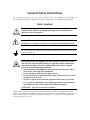
Safety Symbols
Warning
This symbol may appear on the equipment or in the text. It indicates
potential safety hazards regarding product operation or maintenance to
operator or service personnel.
Danger of electric shock! Avoid any contact with the marked surface while
the product is energized or connected to outdoor telecommunication lines.
.
Protective earth: the marked lug or terminal should be connected to the building
protective earth bus.
Warning
Some products may be equipped with a laser diode. In such cases, a label
with the laser class and other warnings as applicable will be attached near
the optical transmitter. The laser warning symbol may be also attached.
Please observe the following precautions:
• Before turning on the equipment, make sure that the fiber optic cable is
intact and is connected to the transmitter.
• Do not attempt to adjust the laser drive current.
• Do not use broken or unterminated fiber-optic cables/connectors or look
straight at the laser beam.
• The use of optical devices with the equipment will increase eye hazard.
• Use of controls, adjustments or performing procedures other than those
specified herein, may result in hazardous radiation exposure.
ATTENTION: The laser beam may be invisible!
Always observe standard safety precautions during installation, operation and maintenance of this
product. Only qualified and authorized service personnel should carry out adjustment, maintenance or
repairs to this product. No installation, adjustment, maintenance or repairs should be performed by
either the operator or the user.
Handling Energized Products
General Safety Practices
Do not touch or tamper with the power supply when the power cord is connected. Line voltages may
be present inside certain products even when the power switch (if installed) is in the OFF position or a
fuse is blown. For DC-powered products, although the voltages levels are usually not hazardous,
energy hazards may still exist.
Before working on equipment connected to power lines or telecommunication lines, remove jewelry
or any other metallic object that may come into contact with energized parts.
Unless otherwise specified, all products are intended to be grounded during normal use. Grounding is
provided by connecting the mains plug to a wall socket with a protective earth terminal. If an earth lug
is provided on the product, it should be connected to the protective earth at all times, by a wire with a
diameter of 18 AWG or wider. Rack-mounted equipment should be mounted only in earthed racks
and cabinets.
Always make the ground connection first and disconnect it last. Do not connect telecommunication
cables to ungrounded equipment. Make sure that all other cables are disconnected before
disconnecting the ground.
Connection of AC Mains
Make sure that the electrical installation complies with local codes.
Always connect the AC plug to a wall socket with a protective ground.
The maximum permissible current capability of the branch distribution circuit that supplies power to
the product is 16A. The circuit breaker in the building installation should have high breaking capacity
and must operate at short-circuit current exceeding 35A.
Always connect the power cord first to the equipment and then to the wall socket. If a power switch is
provided in the equipment, set it to the OFF position. If the power cord cannot be readily
disconnected in case of emergency, make sure that a readily accessible circuit breaker or emergency
switch is installed in the building installation.
Connection of DC Mains
Unless otherwise specified in the manual, the DC input to the equipment is floating in reference to the
ground. Any single pole can be externally grounded.
Due to the high current capability of DC mains systems, care should be taken when connecting the DC
supply to avoid short-circuits and fire hazards.
DC units should be installed in a restricted access area, i.e. an area where access is authorized only to
qualified service and maintenance personnel.
Make sure that the DC supply is electrically isolated from any AC source and that the installation
complies with the local codes.
The maximum permissible current capability of the branch distribution circuit that supplies power to
the product is 16A. The circuit breaker in the building installation should have high breaking capacity
and must operate at short-circuit current exceeding 35A.
Before connecting the DC supply wires, ensure that power is removed form the DC circuit. Locate the
circuit breaker of the panel board that services the equipment and switch it to the OFF position. When
connecting the DC supply wires, first connect the ground wire to the corresponding terminal, then the
positive pole and last the negative pole. Switch the circuit breaker back to the ON position.
A readily accessible disconnect device that is suitably rated and approved should be incorporated in
the building installation.
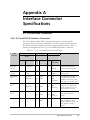
Connection of Data and Telecommunications Cables
Data and telecommunication interfaces are classified according to their safety status.
The following table lists the status of several standard interfaces. If the status of a given port differs from
the standard one, a notice will be given in the manual.
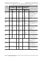
Ports
Safety Status
V.11, V.28, V.35, V.36, RS-530,
X.21, 10 BaseT, 100 BaseT,
Unbalanced E1, E2, E3, STM, DS-2,
DS-3, S-Interface ISDN, Analog voice
E&M
SELV
xDSL (without feeding voltage),
Balanced E1, T1, Sub E1/T1
TNV-1 Telecommunication Network Voltage-1:
FXS (Foreign Exchange Subscriber)
TNV-2 Telecommunication Network Voltage-2:
Safety Extra Low Voltage:
Ports which do not present a safety hazard. Usually
up to 30 VAC or 60 VDC.
Ports whose normal operating voltage is within the
limits of SELV, on which overvoltages from
telecommunications networks are possible.
Ports whose normal operating voltage exceeds the
limits of SELV (usually up to 120 VDC or telephone
ringing voltages), on which overvoltages from
telecommunication networks are not possible. These
ports are not permitted to be directly connected to
external telephone and data lines.
FXO (Foreign Exchange Office), xDSL
(with feeding voltage), U-Interface
ISDN
TNV-3 Telecommunication Network Voltage-3:
Ports whose normal operating voltage exceeds the
limits of SELV (usually up to 120 VDC or telephone
ringing voltages), on which overvoltages from
telecommunication networks are possible.
Always connect a given port to a port of the same safety status. If in doubt, seek the assistance of a
qualified safety engineer.
Always make sure that the equipment is grounded before connecting telecommunication cables. Do
not disconnect the ground connection before disconnecting all telecommunications cables.
Some SELV and non-SELV circuits use the same connectors. Use caution when connecting cables.
Extra caution should be exercised during thunderstorms.
When using shielded or coaxial cables, verify that there is a good ground connection at both ends. The
earthing and bonding of the ground connections should comply with the local codes.
The telecommunication wiring in the building may be damaged or present a fire hazard in case of
contact between exposed external wires and the AC power lines. In order to reduce the risk, there are
restrictions on the diameter of wires in the telecom cables, between the equipment and the mating
connectors.
Caution
Attention
To reduce the risk of fire, use only No. 26 AWG or larger telecommunication line cords.
Pour réduire les risques s’incendie, utiliser seulement des conducteurs de
télécommunications 26 AWG ou de section supérieure.
Some ports are suitable for connection to intra-building or non-exposed wiring or cabling only. In such
cases, a notice will be given in the installation instructions.
Do not attempt to tamper with any carrier-provided equipment or connection hardware.
Electromagnetic Compatibility (EMC)
The equipment is designed and approved to comply with the electromagnetic regulations of major
regulatory bodies. The following instructions may enhance the performance of the equipment and will
provide better protection against excessive emission and better immunity against disturbances.
A good earth connection is essential. When installing the equipment in a rack, make sure to remove all
traces of paint from the mounting points. Use suitable lock-washers and torque. If an external
grounding lug is provided, connect it to the earth bus using braided wire as short as possible.
The equipment is designed to comply with EMC requirements when connecting it with unshielded
twisted pair (UTP) cables. However, the use of shielded wires is always recommended, especially for
high-rate data. In some cases, when unshielded wires are used, ferrite cores should be installed on
certain cables. In such cases, special instructions are provided in the manual.
Disconnect all wires which are not in permanent use, such as cables used for one-time configuration.
The compliance of the equipment with the regulations for conducted emission on the data lines is
dependent on the cable quality. The emission is tested for UTP with 80 dB longitudinal conversion loss
(LCL).
Unless otherwise specified or described in the manual, TNV-1 and TNV-3 ports provide secondary
protection against surges on the data lines. Primary protectors should be provided in the building
installation.
The equipment is designed to provide adequate protection against electro-static discharge (ESD).
However, it is good working practice to use caution when connecting cables terminated with plastic
connectors (without a grounded metal hood, such as flat cables) to sensitive data lines. Before
connecting such cables, discharge yourself by touching earth ground or wear an ESD preventive wrist
strap.
FCC-15 User Information
This equipment has been tested and found to comply with the limits of the Class A digital device,
pursuant to Part 15 of the FCC rules. These limits are designed to provide reasonable protection
against harmful interference when the equipment is operated in a commercial environment. This
equipment generates, uses and can radiate radio frequency energy and, if not installed and used in
accordance with the Installation and Operation manual, may cause harmful interference to the radio
communications. Operation of this equipment in a residential area is likely to cause harmful
interference in which case the user will be required to correct the interference at his own expense.
Canadian Emission Requirements
This Class A digital apparatus meets all the requirements of the Canadian Interference-Causing
Equipment Regulation.
Cet appareil numérique de la classe A respecte toutes les exigences du Règlement sur le matériel
brouilleur du Canada.
Warning per EN 55022 (CISPR-22)
Warning
This is a class A product. In a domestic environment, this product may cause
radio interference, in which case the user will be required to take adequate
measures.
Avertissement
Cet appareil est un appareil de Classe A. Dans un environnement résidentiel, cet
appareil peut provoquer des brouillages radioélectriques. Dans ces cas, il peut
être demandé à l’utilisateur de prendre les mesures appropriées.
Achtung
Dieses ist ein Gerät der Funkstörgrenzwertklasse A. In Wohnbereichen können
bei Betrieb dieses Gerätes Rundfunkströrungen auftreten, in welchen Fällen der
Benutzer für entsprechende Gegenmaßnahmen verantwortlich ist.
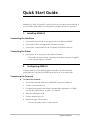
Quick Start Guide
Installation of ASMi-52 should be carried out only by an experienced technician. If
you are familiar with ASMi-52, use this guide to prepare the units for operation.
1.
Installing ASMi-52
Connecting the Interfaces
1. Connect the line to the RJ-45 rear panel connector dedicated SHDSL.
2. Connect the DTE to the appropriate rear panel connector.
3. Connect the control terminal to the rear panel CONTROL connector.
Connecting the Power
•
Connect the AC or DC power to the ASMi-52 modem.
The unit has no power switch. Operation starts when the power is applied
to the rear panel power connector.
2.
Configuring ASMi-52
Configure ASMi-52 to the desired operation mode via an ASCII terminal
connected to the rear panel CONTROL port directly or via a modem link.
Connecting the Terminal
To connect the terminal:
1. Connect the terminal cable to the CONTROL connector of ASMi-52.
2. Turn the control terminal on.
3. Configure the terminal to the default communication parameters: 9.6 kbps,
one start bit, eight data bits, no parity, one stop bit.
4. Select the full-duplex mode.
5. Turn the terminal echo off.
6. Disable any type of flow control.
You are now ready to start a control session.
Configuring ASMi-52
1
ASMi-52 Installation and Operation Manual
Quick Start Guide
Configuring the Master Clock
To configure the master clock:
•
From the System Configuration menu (Main menu > Configuration >
System Configuration > Master Clock), configure the central ASMi-52 clock
to external or internal and remote ASMi-52 clock to the receive clock.
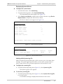
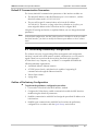
Configuring the SHDSL Interface
To configure the SHDSL interface:
•
From the SHDSL Configuration menu (Main menu > Configuration > Port
Configuration > SHDSL Configuration), configure the following SHDSL
parameters:
SHDSL compatibility
Power backoff
Snext margin, if line probing is set to adaptive
Current margin, if line probing is set to adaptive
Power spectral density (for ASMi-52 with 2-wire line interface and line
probing set to fixed).
Line probing
Line type (for 4-wire ASMi-52 units only)
Loop attenuation threshold
SNR margin threshold.
Configuring the DTE Interface
ASMi-52 includes a serial, E1, T1 or 10/100BaseT DTE interface.
Configuring the Serial Interface
To configure the serial interface:
•
From the DTE Port Configuration (Main menu > Configuration > Port
Configuration > DTE Configuration), select the required data rate.
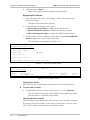
Configuring the E1 Interface
When configuring an E1 interface, you have to select the modem’s framing mode
and assign each E1 timeslot to carry data or idle code.
If in your application, an ASMi-52 unit with an E1 interface operates opposite
another ASMi-52 unit, the E1 settings of the remote device are automatically
matched to those of the local modem (the Units Identical Setting value is set to YES
by default). The Units Identical Setting value of the local modem overrides the
management commands of the remote supervisory terminal.
2
Configuring ASMi-52
ASMi-52 Installation and Operation Manual
Quick Start Guide
To configure E1 parameters:
•
From the E1 Port Configuration menu (Main menu > Configuration > Port
Configuration > E1 Port Configuration), configure the following E1
parameters:
Framing mode
Timeslot assignment.
Note
•
You can configure timeslot 0 to be looped or transparent:
Looped – timeslot 0 is sent back to the E1 interface, when operating
opposite remote units with a serial data interface.
Transparent – timeslot 0 is transmitted to the remote modem.
•
If you operate ASMi-52 with the G732S framing, timeslot 0 is always
transparent and timeslot 16 is always connected.
•
When operating a 2-wire ASMi-52 with E1 interface opposite ASMi-52 with
V.35 interface (not in LS mode), assign at least three timeslots, excluding
timeslot 0, to carry data.
•
When operating a 4-wire ASMi-52 with E1 interface opposite ASMi-52 with
V.35 interface (not in LS mode), assign at least six timeslots, excluding timeslot
0, to carry data.
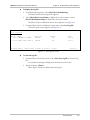
Configuring the T1 Interface
To configure T1 parameters:
•
From the T1 Port Configuration menu (Main menu > Configuration > Port
Configuration > T1 Port Configuration), configure the following T1 parameters:
Framing mode
Line coding
Receive gain
Interface type
Transmit signal mask
Timeslot assignment.
Configuring the 10/100BaseT Interface
To configure 10/100BaseT parameters:
•
From the LAN Configuration menu (Main menu > Configuration > System
Configuration > LAN Configuration), configure the following LAN parameters:
Operation mode
Bridge static table
Aging timeout
LAN rate.
Configuring ASMi-52
3
Quick Start Guide
4
Configuring ASMi-52
ASMi-52 Installation and Operation Manual
Contents
Chapter 1. Introduction
1.1 Overview..................................................................................................................... 1-1
Versions................................................................................................................................ 1-1
Applications.......................................................................................................................... 1-2
Features................................................................................................................................ 1-2
1.2 Physical Description..................................................................................................... 1-6
1.3 Functional Description................................................................................................. 1-7
1.4 Technical Specifications............................................................................................... 1-8
Chapter 2. Installation and Setup
2.1 Site Requirements and Prerequisites ............................................................................ 2-1
2.2 Package Contents ........................................................................................................ 2-2
2.3 Installation and Setup .................................................................................................. 2-2
Connecting the Interfaces ..................................................................................................... 2-3
Connecting the Power .......................................................................................................... 2-4
Chapter 3. Operation
3.1 Indicators..................................................................................................................... 3-1
3.2 Operating ASMi-52...................................................................................................... 3-2
Turning On ASMi-52 ............................................................................................................ 3-2
Normal Indications ............................................................................................................... 3-3
Turning Off ASMi-52 ............................................................................................................ 3-3
3.3 Default Settings............................................................................................................ 3-3
Chapter 4. Managing ASMi-52 via a Terminal
4.1 Preparing for a Control Session .................................................................................... 4-1
Managing ASMi-52 via Terminal Port .................................................................................... 4-1
Managing ASMi-52 via Ethernet Port ..................................................................................... 4-2
Managing ASMi-52 via Dedicated Timeslot ...........................................................................4-3
4.2 Navigating the Management Menus............................................................................. 4-4
Choosing Options ................................................................................................................. 4-4
Correcting Entries ................................................................................................................. 4-4
Navigating Data Forms..........................................................................................................4-4
Navigating the ConfiguRAD Menus ....................................................................................... 4-5
Logging Out.......................................................................................................................... 4-5
4.3 Entering the User Name and Password ........................................................................ 4-5
4.4 Displaying the ASMi-52 Inventory................................................................................ 4-7
4.5 Configuring ASMi-52 System Parameters ..................................................................... 4-8
Configuring the Master Clock ................................................................................................4-9
Configuring Low Speed Operation ...................................................................................... 4-10
Configuring Management Parameters.................................................................................. 4-10
Configuring the LAN Port .................................................................................................... 4-15
Configuring Control Port Parameters ................................................................................... 4-19
Changing the Terminal Parameters ...................................................................................... 4-20
4.6 Configuring the Physical Ports .................................................................................... 4-24
ASMi-52 Installation and Operation Manual
i
Table of Contents
Configuring the SHDSL Interface......................................................................................... 4-25
Configuring the Serial DTE Interface.................................................................................... 4-29
Configuring the E1 Interface................................................................................................ 4-31
Configuring the T1 Interface................................................................................................ 4-36
4.7 Displaying the ASMi-52 Status ................................................................................... 4-37
Displaying the System Status ...............................................................................................4-38
Displaying the Port Status....................................................................................................4-38
4.8 Accessing the Remote ASMi-52 ................................................................................. 4-39
4.9 Updating Software Releases ....................................................................................... 4-40
Installing a New Software Release via TFTP ......................................................................... 4-40
Installing a New Software Release via XMODEM ................................................................. 4-41
Displaying the Software Version .......................................................................................... 4-41
Switching the Software Versions .......................................................................................... 4-42
4.10 Resetting ASMi-52 ..................................................................................................... 4-43
Resetting to Default Settings................................................................................................ 4-43
Resetting the ASMi-52 Modem ........................................................................................... 4-44
Resetting the SHDSL Repeater ............................................................................................ 4-44
4.11 Exiting the Control Session......................................................................................... 4-45
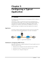
Chapter 5. Configuring a Typical Application
5.1 Overview..................................................................................................................... 5-1
Application ........................................................................................................................... 5-1
Guidelines for Configuring ASMi-52 Units ............................................................................. 5-1
5.2 Configuring the ASMi-52 units ..................................................................................... 5-2
Setting the ASMi-52 System .................................................................................................. 5-2
Setting the Line Interface ...................................................................................................... 5-3
Setting the E1 port ................................................................................................................ 5-4
Chapter 6. Troubleshooting and Diagnostics
6.1 Error Detection ............................................................................................................ 6-1
Power-Up Self-Test ............................................................................................................... 6-1
Front Panel LEDs .................................................................................................................. 6-1
Displaying Alarms ................................................................................................................. 6-1
6.2 Displaying SHDSL Statistics.......................................................................................... 6-9
Displaying the Current SHDSL Statistics................................................................................. 6-9
Displaying the SHDSL Statistics for all Intervals .................................................................... 6-11
Clearing the SHDSL Statistics ..............................................................................................6-12
6.3 Displaying E1/T1 Statistics.......................................................................................... 6-12
Displaying the Current E1/T1 Statistics................................................................................. 6-13
Displaying E1 Statistics for all Intervals ................................................................................. 6-15
Clearing the E1 Statistics ..................................................................................................... 6-16
6.4 Performing the Diagnostic Tests ................................................................................. 6-16
Running Loopback Tests ..................................................................................................... 6-16
Running the LEDs Test ........................................................................................................ 6-20
6.5 Technical Support...................................................................................................... 6-20
Appendix A. Interface Connector Specifications
Appendix B. IR-IP Interface Module
Appendix C. Configuration Menus
ii
ASMi-52 Installation and Operation Manual
Chapter 1
Introduction
1.1 Overview
ASMi-52 is an SHDSL modem, which operates in full duplex over 2/4-wire lines
and offers a cost-effective solution for delivering digital data to customer premises
over the existing copper cables. ASMi-52 handles multiple data rates in the range
of 64–4608 kbps. The modem supports X.21, V.35, RS-530, E1 and T1 interfaces.
In addition, ASMi-52 may contain an Ethernet/Fast Ethernet bridge with VLAN
support (via management LAN port) or an IP router (IR-IP).
ASMi-52 uses TC-PAM coding and complies with the ITU-T G.991.2 requirements.
Versions
Line Interface
•
ASMi-52 for operation over 2-wire line
•
ASMi-52 for operation over 4-wire line.
Unit Enclosure
ASMi-52 is available in a plastic or metal enclosure.
Overview
1-1
ASMi-52 Installation and Operation Manual
Chapter 1 Introduction
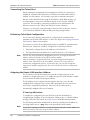
Applications
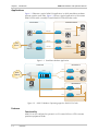
Figure 1-1 illustrates a typical ASMi-52 application, in which standalone modems
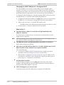
operate opposite each other. Figure 1-2 shows a typical application of the remote
ASMi-52 units with a centrally located ASMi-52CD dual modem cards.
Central Office
Customer Premises
Fast Ethernet
SNMP
Management
Station
2048 kbps
E1
ASMi-52
ASMi-52
E1
10/100BT LAN
PBX
PBX
768 kbps
ASMi-52
Public
Network
V.35
ASMi-52
Router
1152 kbps
SNMP
Management
Station
Fast Ethernet
Multiplexer
ASMi-52
ASMi-52
10/100BT LAN
Figure 1-1. Standalone Modem Application
Remote Site A
Central Site
LRS-24
4-wire
V.35
ASMi-52
Public
Network
Router
4-wire
V.35
ASMi-52CD ASMi-52CD/4
ASMi-52
Router
Remote Site B
SNMP
Management
Station
2-wire
Ethernet
ASMi-52
2-wire
Ethernet
ASMi-52
Figure 1-2. ASMi-52 Modems Operating opposite ASMi-52CD Cards
Features
Functionality
ASMi-52 can be configured to operate in a CO (central office) or CPE (customer
premises equipment) mode.
1-2
Overview
ASMi-52 Installation and Operation Manual
Chapter 1 Introduction
Line Interface
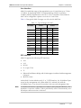
ASMi-52 extends the range of data transmission over 2/4-wire lines up to 7.0 km
(4.3 miles), by employing SHDSL TC-PAM technology. ASMi-52 operation
complies with the requirements of the ITU-T G.991.2 standard. 4-wire ASMi-52
units can be configured to operate over 4-wire or 2-wire lines.
Table 1-1 lists typical ASMi-52 ranges over 2/4-wire 26 AWG line.
Table 1-1. Typical Ranges (26 AWG)
Data Rate
2-wire
4-wire
[kbps]
[km]
[miles]
[km]
[miles]
64
7.5
4.6
–
–
128
7.0
4.3
7.1
4.4
256
6.7
4.1
6.8
4.2
384
6.5
4.0
6.7
4.1
512
6.3
3.9
6.6
4.1
1024
5.3
3.3
6.0
3.7
1536
5.0
3.1
5.6
3.5
2048
4.5
2.8
4.7
2.9
2304
4.2
2.6
4.5
2.8
4096
–
–
3.7
2.3
4608
–
–
3.0
1.8
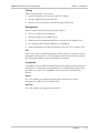
DTE Interface
ASMi-52 supports the following DTE interfaces:
• X.21
•
V.35
•
RS-530
•
E1, as per G.704
•
T1
•
Ethernet/Fast Ethernet bridge with VLAN support (combined with management
LAN port)
•
IR-IP (IP router).
In the ASMi-52 units with the serial, E1 or T1 DTE interface, the 10/100BaseT port
serves for the management only. When ASMi-52 is ordered only with the
10/100BaseT port, it can be used for transfer of the user and management data.
Note
E1 unbalanced interface is provided via an adapter cable (CBL-RJ45/2BNC/E1). The
impedance conversion (120Ω to 75Ω) is performed by ASMi-52 automatically, once
the adapter cable connection is detected.
Overview
1-3
ASMi-52 Installation and Operation Manual
Chapter 1 Introduction
ASMi-52 supports multiple data rates in the range between 64 kbps and
4608 kbps. Data rate depends on the following factors:
• Unit rate mode (regular or low speed)
•
Line interface type (2-wire or 4-wire)
•
DTE interface type of the local and remote units (serial or E1)
•
Clock mode (internal or external).
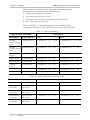
Table 1-2 and Table 1-3 detail the ASMi-52 data rates with all possible
combinations of rate mode types, line/DTE interface types, and clock modes.
Table 1-2. ASMi-52 Data Rates
DTE Interface & Clock Mode
Line Interface
Local ASMi-52
Remote ASMi-52
2-wire
4-wire
Serial DTE
interface, internal
clock
Serial DTE interface
N × 64 kbps (N = 1, 2, … 32, 36)
N × 128 kbps (N = 1, 2, …32, 36)
Serial DTE interface
Serial DTE
interface, external
clock
N × 64 kbps (N = 1, 2, …, 36)
N × 128 kbps (N = 1, 2, …, 36)
Serial DTE
interface
E1 DTE interface
N × 64 kbps (N = 3, 4, …, 32)
N × 128 kbps (N = 3, 4, …, 16)
E1 DTE interface
Serial DTE interface
N × 64 kbps (N = 3, 4, …, 32)
N × 128 kbps (N = 3, 4, …, 16)
E1 DTE interface
E1 DTE interface
N × 64 kbps (N = 1, 2, …, 32)
N × 64 kbps (N = 1, 2, …, 32)
Serial DTE
interface
T1 DTE interface
N × 64 kbps (N = 3, 4, …, 24)
N × 128 kbps (N = 3, 4, …, 12)
T1 DTE interface
Serial DTE interface
N × 64 kbps (N = 3, 4, …, 24)
N × 128 kbps (N = 3, 4, …, 12)
T1 DTE interface
T1 DTE interface
N × 64 kbps (N = 1, 2, …, 24)
N × 64 kbps (N = 1, 2, …, 24)
Table 1-3. ASMi-52 Data Rates (Low Speed Mode)
Unit and DTE Interface Type
Line Interface
Local Unit
Remote Unit
2-wire
4-wire
ASMi-52 in low
speed mode
ASMi-52 in low
speed mode
N × 64 kbps (N = 1, 2, …, 32)
N × 64 kbps (N = 1, 2, …, 32)
ASMi-52 in low
speed mode
ASMi-52 with serial
DTE interface
N × 64 kbps (N = 3, 4, …, 32)
N × 128 kbps (N = 3, 4, …, 16)
ASMi-52 in low
speed mode
ASMi-52 with E1
DTE interface
N × 64 kbps (N = 1, 2, …, 32)
N × 64 kbps (N = 1, 2, …, 32)
ASMi-52 in low
speed mode
ASMi-52 with T1
DTE interface
N × 64 kbps (N = 1, 2, …, 24)
N × 64 kbps (N = 1, 2, …, 24)
1-4
Overview
ASMi-52 Installation and Operation Manual
Chapter 1 Introduction
Timing
ASMi-52 supports three clock modes:
• Internal, derived from its internal oscillator (CO mode)
•
External, supplied by the attached DTE
•
Receive, recovered from the received line signal (CPE mode).
Management
ASMi-52 supports the following management options:
•
SLIP via V.24 (RS-232) terminal port
•
Telnet via dedicated 10/100BaseT port
•
SNMP network management (RADview) via dedicated 10/100BaseT port
•
PC, running a Web browsing application (ConfiguRAD)
•
Inband management via dedicated timeslot (units with E1/T1 interface only).
EOC
ASMi-52 provides an inband management channel (EOC) for end-to-end system
management and supervision. This management channel uses SHDSL overhead
bits and operates without interfering with data transmission.
ConfiguRAD
ConfiguRAD is user-friendly Web-based terminal management system serving for
remote device configuration and maintenance. It is embedded in ASMi-52 and
provided at no extra cost. ConfiguRAD can be run from any standard Web
browser.
Dial-In
The V.24 terminal port supports dial-up modem connection for remote
management of ASMi-52 over telephone lines.
Dial-Out
The V.24 terminal port supports alarm dial-out.
Overview
1-5
ASMi-52 Installation and Operation Manual
Chapter 1 Introduction
Diagnostics
ASMi-52 supports activation of the following:
• Local loopback
•
Remote loopback
•
Remote loopback at SHDSL repeater (activated from the local unit).
All tests can be activated from the local unit or from the remote unit.
Real time alarms provide information on the system status, indicating management
failure, synchronization loss and other conditions.
Statistic Collection
ASMi-52 supports SHDSL and E1/T1 statistics collection.
Alarm Reporting
ASMi-52 alarms are relayed via dedicated 6-pin terminal block connector.
SHDSL Repeaters
Up to eight SHDSL repeaters can be installed in line to increase the operation
range of the modem. ASMi-52 provides basic management of the repeaters.
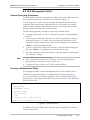
1.2 Physical Description
Figure 1-3 shows a 3D view of the ASMi-52 unit in the plastic enclosure.
Figure 1-3. ASMi-52, 3D View
The front panel includes several LEDs, which display the status of power, data flow
and provide diagnostics. For a detailed description of the front panel, see Chapter 3.
The rear panel includes AC/DC power connector, a DTE connector, a line
connector, 10/100BT port, V.24 terminal connector and alarm relay port. The
ASMi-52 rear panel is described in greater detail in Chapter 2.
1-6
Physical Description
ASMi-52 Installation and Operation Manual
Chapter 1 Introduction
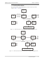
1.3 Functional Description
This section provides a functional description of ASMi-52 in the form of block
diagrams (Figure 1-4 and Figure 1-5).
Internal
Oscillator
Data & Clock
DTE
Interface
Control Signals
Modem Glue
Logic
SHDSL
Line Interface
CPU Data Bus
Power
Supply
CPU
10/100BaseT
Management
Port
LEDs and Terminal Interface
Figure 1-4. ASMi-52/4W with V.35 Interface and 10/100BaseT Management Port
Internal
Oscillator
DTE
Interface
Data, Clock, Sync
Modem Glue
Logic
SHDSL
Line Interface
CPU Data Bus
Power
Supply
10/100BaseT
Management
Port
CPU
LEDs and Terminal Interface
Figure 1-5. ASMi-52/4W with Framed E1 Interface and 10/100BaseT Management Port
Functional Description
1-7
ASMi-52 Installation and Operation Manual
Chapter 1 Introduction
The ASMi-52 modem consists of the following major modules:
DTE interface – Prepares the digital data coming from the DTE into a data stream for the
modem glue logic. In addition it translates the data from the modem glue
logic into digital data to be sent to the DTE.
Internal oscillator – Serves as a source of internal clock for the ASMi-52 unit.
Modem glue logic module – Processes the data from/to the SHDSL interface module.
SHDSL line interface – Translates the received and transmitted data from the line to the
DTE interface.
Power supply – Provides 2.5V, 3.3V, 5V and -5V voltage to the ASMi-52 internal
elements.
CPU – Controls the ASMi-52 operation.
10/100BaseT management port – Provides LAN connection to the SNMP management
station or Telnet host.
LEDs and terminal interface – Provides modem status information via LED indicators on
the front panel, and communicates with the supervisory terminal.
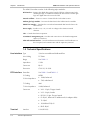
1.4 Technical Specifications
Line Interface Type
2/4-wire unconditioned dedicated line
Line Coding
TC-PAM
Range
See Table 1-1
Impedance
135Ω
Connector
RJ-45
Protection
ITU K.21, UL1950
DTE Interface Data Rate
See Table 1-2 and Table 1-3
E1 Coding
HDB3
E1 Line Impedance
• 120Ω, balanced
• 75Ω, unbalanced
T1 Coding
AMI
T1 Line Impedance
100Ω, balanced
Connector
• X.21: 15-pin, D-type, female
• V.35: 34-pin, female
• RS-530: 25-pin, D-type, female
• E1: RJ-45, balanced or unbalanced (via adapter cable)
• T1: RJ-45
• 10/100BaseT: RJ-45
• IR-IP: RJ-45
Terminal
1-8
Interface
Technical Specifications
V.24 (RS-232)
ASMi-52 Installation and Operation Manual
Control Port
Ethernet
Control Port
Chapter 1 Introduction
Type
DTE/DCE
Format
8 bits, no parity
Baud Rate
9.6, 19.2, 38.4, 57.6, 115.2 kbps
Connector
9-pin, D-type female
Interface
10/100BaseT
Protocol
MAC
Connector
RJ-45
Derived from three alternative sources:
Timing
• Internal oscillator
• External, from the attached DTE
• Receive, derived from the received signal
Diagnostics
Loopbacks
ITU V.54:
• Local loopback, activated via management software or by
the DTE interface signal (V.35 and RS-530 only)
• Remote loopback, activated via management software or
by the DTE interface signal (V.35 and RS-530 only)
• Remote loopback at SHDSL repeater
Statistics Collection
• E1 with CRC-4 or T1 with ESF framing: per ITU G.706
• E1 without CRC-4 or T1 with SF framing: bipolar
violations (BPV)
• SHDSL performance
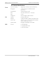
Alarm Relay
Indicators
Operation
Normally Open and Normally Closed, using different pins
Connector
Terminal block, 6-pin
PWR (green)
Power
TEST (red)
Test
SYNC A/B
(green/red)
Synchronization of DSL line
DATA (yellow)
Data Transfer (except E1 and T1 options)
E1/T1 SYNC (red)
Loss of E1/T1 synchronization (E1 and T1 options only)
AIS (yellow)
“All 1s string” is received at the E1 interface
(E1 option only)
YELLOW (yellow)
“All 1s string” is received at the T1 interface
(T1 option only)
ALM (red)
Alarm
Technical Specifications
1-9
ASMi-52 Installation and Operation Manual
Chapter 1 Introduction
Physical
Plastic Enclosure
Height
43.7 mm / 1.7 in
Width
240 mm / 9.4 in
Depth
170.5 mm / 6.7 in
Weight
0.5 kg
/ 1.1 lb
Metal Enclosure
Height
47.3 mm / 1.8 in
Width
215 mm / 8.4 in
Depth
147 mm / 5.8 in
Weight
0.7 kg
Power Source AC/DC Voltage
Power Consumption
/ 1.5 lb
Wide range power supply:
100–240 VAC or -40/60 VDC
DC only:
24 VDC
2-wire: 6W max
4-wire: 7W max
Environment Temperature
Humidity
1-10
Technical Specifications
0–50°C / 32–122°F
Up to 90%, non–condensing
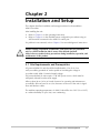
Chapter 2
Installation and Setup
This chapter describes installation and setup procedures for the standalone
ASMi-52 modem.
After installing the unit:
• Refer to Chapter 3 for the operating instructions.
•
Refer to Chapter 4 for the detailed system configuration procedures using an
ASCII terminal connected to the ASMi-52 control port.
If a problem is encountered, refer to Chapter 5 for test and diagnostic instructions.
Warning
Internal settings, adjustment, maintenance, and repairs may be performed
only by a skilled technician who is aware of the hazards involved.
Always observe standard safety precautions during installation, operation, and
maintenance of this product.
2.1 Site Requirements and Prerequisites
AC-powered ASMi-52 units should be installed within 1.5m (5 ft) of an
easily-accessible grounded AC outlet capable of furnishing the voltage in
accordance with ASMi-52 nominal supply voltage.
DC-powered ASMi-52 units require a -48 VDC power source, which must be
adequately isolated from the main supply.
Allow at least 90 cm (36 in) of frontal clearance for operating and maintenance
accessibility. Allow at least 10 cm (4 in) clearance at the rear of the unit for signal
lines and interface cables.
The ambient operating temperature of ASMi-52 should be 0 to 50°C (32 to 122°F),
at a relative humidity of up to 90%, non-condensing.
Site Requirements and Prerequisites
2-1
Chapter 2 Installation and Setup
ASMi-52 Installation and Operation Manual
2.2 Package Contents
The ASMi-52 package includes the following items:
• One ASMi-52 unit
•
Technical documentation CD
•
Power connection accessories (depending on which power option was
ordered):
Power cord (VAC) and AC/DC plug (-48 VDC)
Terminal block kit (24 VDC)
•
CBL-RJ45/2BNC/E1 adapter cable for unbalanced E1 interface (if ordered)
•
RM-33 rack mount kit for the plastic case unit (if ordered)
•
RM-35 rack mount kit for the metal case unit (if ordered).
2.3 Installation and Setup
The ASMi-52 standalone unit is designed for desktop or bench installation and is
delivered as a fully assembled unit. No provisions are made for bolting the unit to
a tabletop.
To install ASMi-52:
1. Determine the required configuration of ASMi-52, in accordance with your
application.
2. Connect the line (see Connecting the Line below).
3. Connect the DTE (see Connecting the DTE below).
4. Connect power to the unit (see Connecting the Power below).
2-2
Installation and Setup
ASMi-52 Installation and Operation Manual
Chapter 2 Installation and Setup
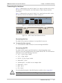
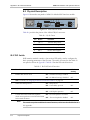
Connecting the Interfaces
Figure 2-1 illustrates the rear panel of ASMi-52 in a plastic enclosure with a 4-wire
line interface, E1 DTE interface, user LAN interface, alarm relay port and the
control port.
Figure 2-2 illustrates the rear panel of ASMi-52 in a metal enclosure with a 4-wire
line interface, the user LAN interface, and the control port.
ALARM
LINK
TX
12
RX
45
LINE LINE
B
A
1 2 4 5
DCE
SHDSL
V.35
ACT
CONTROL
E1/T1
Figure 2-1. ASMi-52 Rear Panel (Plastic Enclosure)
LINE LINE
B
A
12 45
LINK
ACT
CONTROL
SHDSL
Figure 2-2. ASMi-52 Rear Panel (Metal Enclosure)
Connecting the Line
The ASMi-52 line interface terminates in an 8-pin RJ-45 connector.
To connect the line connector:
•
Connect the line cable to the RJ-45 connector designated SHDSL.
Connecting the DTE
The ASMi-52 DTE interface provides interface for input/output data, clock
reference and control signals between the modem and the DTE. The DTE interface
terminates in one of the following connectors:
•
X.21 – 15-pin, D-type, female
•
V.35 – 34-pin, female
•
RS-530 – 25-pin, D-type, female
•
Balanced E1 – RJ-45
•
Unbalanced E1 – two BNC coax via adapter cable
•
Balanced T1 – RJ-45
•
IR-IP – RJ-45
•
ETH – RJ-45.
For the detailed description of the IR-IP interface module, refer to Appendix B.
Warning
The E1/T1 port is intended for intra-building non-exposed plant only.
Installation and Setup
2-3
Chapter 2 Installation and Setup
ASMi-52 Installation and Operation Manual
To connect the DTE:
•
Connect the DTE to the appropriate rear panel DTE interface connector of the
ASMi-52 modem.
Appendix A specifies the DTE connector pinouts.
Connecting the Alarm Relay Connector
To connect the alarm relay:
•
Connect external alarm device to the rear panel terminal block connector
designated ALARM. Refer to Appendix A for the connector pinout and alarm
functions.
Connecting the Power
ASMi-52 is equipped with a dual input AC/DC power supply. AC or DC power is
supplied to ASMi-52 via a standard 3-prong power input connector on the rear
panel (see Figure 2-1).
Warning
Before connecting this unit to power and connecting or disconnecting any
other cable, the protective earth terminals of this unit must be connected to
the protective ground conductor of the mains (AC or DC) power cord. If you
are using an extension cord (power cable) make sure it is grounded as well.
Any interruption of the protective (grounding) conductor (inside or outside the
instrument) or disconnecting of the protective earth terminal can make this
unit dangerous. Intentional interruption is prohibited.
Connecting AC Power
AC power should be supplied through the 1.5m (5 ft) standard power cable
terminated by a standard 3-prong plug. The cable is provided with the unit.
To connect AC power:
1. Connect the power cable to the power connector on the ASMi-52 rear panel.
2. Connect the power cable to the mains outlet.
The unit turns on automatically upon connection to the mains.
Connecting DC Power
DC power is supplied to ASMi-52 via compatible AC/DC plug for attaching DC
power supply lines.
To connect DC power:
•
2-4
Refer to the DC power supply connection supplement.
Installation and Setup
Chapter 3
Operation
This chapter provides the following information for the ASMi-52 modem:
•
ASMi-52 front-panel indicators
•
Operating procedures (turn-on, front-panel indications, performance
monitoring and turn-off).
•
ASMi-52 default settings.
Installation procedures given in Chapter 2 must be completed and checked before
attempting to operate ASMi-52.
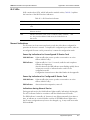
3.1 Indicators
The front and rear panels of ASMi-52 include a series of LED indicators that show
the current operating status of the unit.
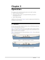
Figure 3-1 shows the front panel of the 2-wire ASMi-52 unit in a plastic enclosure
with an E1 interface. Figure 3-2 illustrates front panel of the 4-wire ASMi-52 unit a
plastic enclosure with a V.35 interface.
Table 3-1 lists and describes the front panel indicators. Table 3-2 lists and describes
the rear panel indicators
ASMi-52
Figure 3-1. ASMi-52 Front Panel, E1 Interface
ASMi-52
Figure 3-2. ASMi-52 Front Panel, V.35 Interface
Indicators
3-1
ASMi-52 Installation and Operation Manual
Chapter 3 Operation
Table 3-1. ASMi-52 Front Panel LEDs
Name
Function
PWR (green)
On – Power is ON
TST (red)
On – A loopback test is active in local or remote unit
SYNC A
(red/green)
On (red) – Link A is not synchronized
On (green) – Link A is synchronized
Blinks – The line is connected properly and the
synchronization process is taking place
SYNC B
(red/green)
On (red) – Link B is not synchronized
On (green) – Link B is synchronized
Blinking – The line B is connected properly and the
synchronization process is taking place
AIS (yellow)
On – “All 1s string” is received at the E1 interface
YELLOW (yellow)
On – “All 1s string” is received at the T1 interface
E1/T1 SYNC (red)
On – Loss of E1 or T1 synchronization
DATA (yellow)
Blinking – Data is being transferred
ALM (red)
On – An alarm enters the buffer of local or remote unit
Table 3-2. ASMi-52 Rear Panel LEDs
Name
Function
ACT (yellow)
Blinks according to Ethernet traffic activity (10/100BaseT
connector)
LINK (green)
On – Good link integrity (10/100BaseT connector)
3.2 Operating ASMi-52
Turning On ASMi-52
To turn on ASMi-52:
• Connect the power cord to the mains.
The PWR indicator lights up and remains lit as long as ASMi-52 receives
power.
ASMi-52 requires no operator attention once installed, with the exception of
occasional monitoring of front panel indicators. Intervention is only required when
ASMi-52 must be configured to its operational requirements, or diagnostic tests are
performed.
3-2
Operating ASMi-52
ASMi-52 Installation and Operation Manual
Chapter 3 Operation
Normal Indications
Upon turning on ASMi-52, the PWR LED in the front panel lights to indicate that
ASMi-52 is on. Table 3-3 shows the correct status of the indicators a few seconds
after the units were synchronized.
Table 3-3. ASMi-52 Indicator Status
Indicator
Status
PWR
ON
TST
OFF
ALM
OFF
SYNC
ON (green)
If the above LED indications do not appear following initial power turn-on, refer to
Chapter 5 for the diagnostic test instructions.
Turning Off ASMi-52
To turn off ASMi-52:
•
Remove the power cord from the power source.
3.3 Default Settings
ASMi-52 is managed by an ASCII terminal or PC running a terminal emulation
program via menu-driven embedded software. Table 3-4 lists the default settings of
the ASMi-52 configuration parameters.
Table 3-4. Default Settings
Parameter
Default Value
System
Clock
Internal
Sys contact
–
Sys location
–
Sys name
–
Host IP address
0.0.0.0
Host IP mask
0.0.0.0
Host default gateway
0.0.0.0
Read community
public
Write community
public
Trap community
public
SNMP allowed
Access allowed
Default Settings
3-3
ASMi-52 Installation and Operation Manual
Chapter 3 Operation
Table 3-4. Default Settings (Cont.)
3-4
Parameter
Default Value
Telnet allowed
Access allowed
WEB allowed
Access allowed
Bootp state
OFF
DTS IP address
0.0.0.0
DTS IP mask
0.0.0.0
LAN operation mode
Transparent
Encapsulation CRC
No
Bridging Mode
Access only
Aging Timeout
10
Autonegotiation
Enable
Max AutoNeg Capability
100BASE_T-full duplex mode
Control port rate
9600 bps
Data
8
Parity
None
Interface
DCE
CTS
=RTS
DSR
ON
Port control mode
Terminal
User name
–
Password
1234
Pop alarm
OFF
Security timeout
10 min
Call Out Mode
None
Number of retries
1
Wait for connect
30 sec
Dial mode
Tone
Alternate number mode
Disable
Primary number
–
Alternate number
–
Default Settings
ASMi-52 Installation and Operation Manual
Chapter 3 Operation
Table 3-4. Default Settings (Cont.)
Parameter
Default Value
SHDSL Interface
Transmission mode
Annex B
Power backoff
Enable
Snext margin
Disable
Current margin
Disable
Asym PSD
Symmetrical
Line prob
Fixed rate
Note: ASMi-52 units with 4-wire line interface support only fixed rate.
Configured wire
4w
Loop attenuation threshold
0
SNR margin threshold
0
Serial DTE Interface
Rate
ASMi-52, 2-wire and V.35 – 192 kbps
ASMi-52, 4-wire and V.35 – 384 kbps
LLB from DTE
Disable
RLB from DTE
Disable
E1 Interface
Framed mode
Unframed
Sync
CCITT
CRC-4
No
Idle Code
ff
Units identical settings
Yes
T1 Interface
Framed mode
Unframed
Line code
B8ZS
Receive gain
Long
Interface
DSU
Transmit signal mask
0 feet
Fbit configuration
Transparent
Sync mode
Fast (after 1 sec)
Idle code
ff
Units identical set
Yes
Default Settings
3-5
Chapter 3 Operation
3-6
Default Settings
ASMi-52 Installation and Operation Manual
Chapter 4
Managing ASMi-52 via a
Terminal
The configuration of ASMi-52 is performed via menu-driven embedded software,
using a standard ASCII terminal or a PC running a terminal emulation application
connected to the rear panel CONTROL port. Alternatively, ASMi-52 can be
managed from a Telnet host connected to the 10/100BASE-T port on the rear
panel.
4.1 Preparing for a Control Session
This section describes how to prepare ASMi-52 and the supervisory terminal for a
control session.
Managing ASMi-52 via Terminal Port
Control Port Interface Characteristics
ASMi-52 includes a V.24 (RS-232) asynchronous DCE port, designated CONTROL
and terminated in a 9-pin D-type female connector. The control port continuously
monitors the incoming data stream and immediately responds to any input string
received through this port.
The terminal can be connected either directly to the ASMi-52 control port, or
through a modem or any other type of full-duplex data link. The ASMi-52 control
port interface type must be set in accordance with the connection method, as
follows:
•
DCE – direct connection to terminals. Since terminals usually have DTE
interfaces, the connection to the port is made by means of a straight-through
cable.
•
DTE – connection through a modem or data link. In this case, you need a cross
cable (also called a null modem cable) to connect to the CONTROL connector.
The ASMi-52 control port can be configured to communicate at the following rates:
9.6, 19.2, 38.4, 57.6 or 115.2 kbps.
The word format consists of one stop bit, 8 data bits, and no parity.
Preparing for a Control Session
4-1
Chapter 4 Managing ASMi-52 via a Terminal
ASMi-52 Installation and Operation Manual
Preparing the Terminal
Any standard ASCII terminal (a “dumb” terminal or a personal computer running
a terminal emulation application) equipped with a V.24 (RS-232) communication
interface can be used to configure ASMi-52. Appendix A details the pin assignment
and control signal directions of the ASMi-52 control connector.
Data Terminal Ready (DTR)
When connected and turned on, the terminal sets the DTR line ON (active) to gain
control over ASMi-52 and starts a configuration or monitoring session.
Initiating a Control Session
To initiate a control session:
1. Connect the terminal cable to the CONTROL connector of ASMi-52.
2. Turn the control terminal on.
3. Configure the terminal to the default communication parameters: 9.6 kbps, one
start bit, eight data bits, no parity, one stop bit, VT100 emulation.
4. Select the full duplex mode.
5. Turn the terminal echo off.
6. Disable any type of flow control.
You are now ready to start a control session.
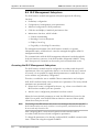
Managing ASMi-52 via Ethernet Port
ASMi-52 is equipped with an Ethernet/Fast Ethernet port (10/100BASE-T) which
enables communication with ASMi-52 management subsystem using the IP protocol
(see Figure 4-2). The Ethernet management port is configured for LAN cross-over
connection.
To prepare ASMi-52 for network management:
1. Connect a LAN network management station to the ASMi-52 Ethernet port
designated 10/100BASE-T.
2. Configure the host IP parameters of the ASMi-52 unit via an ASCII terminal.
3. Run an SNMP management application, such as RAD’s RADview, open Telnet
session, or manage ASMi-52 via ConfiguRAD.
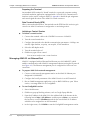
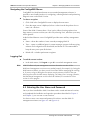
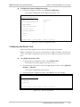
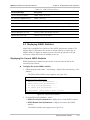
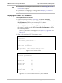
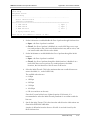
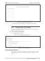
To start ConfiguRAD session:
1. Start a Web browser.
2. Disable any pop-up blocking software, such as Google Popup Blocker.
3. Enter the IP address of the ASMi-52 in the address field of the browser in the
following format: http://<IP address> and then press <Enter> to command
the browser to connect (IP address stands for the actual ASMi-52 IP address
which has to be assigned via an ASCII terminal).
4. In the Login screen, click LOGIN to start the ConfiguRAD management session.
4-2
Preparing for a Control Session
ASMi-52 Installation and Operation Manual
Chapter 4 Managing ASMi-52 via a Terminal
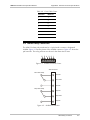
Figure 4-1. ConfiguRAD Login
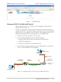
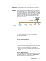
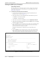
Managing ASMi-52 via Dedicated Timeslot
ASMi-52 modems with E1 or T1 interface can be managed via dedicated E1/T1
timeslot (DTS) (see Figure 4-2).
The DTS is a management channel that connects directly to ASMi-52 host using a
separate IP interface, i.e. separate IP address and IP mask. If the LAN and dedicated
timeslot services are configured to have the same IP, the management session over
dedicated timeslot has priority over management via 10/100BaseT port.
1. Connect E1/T1 line to the ASMi-52 E1 or T1 port.
2. Start a terminal management session and do the following:
Assign IP address and IP mask to the dedicated timeslot interface
Enable DTS management
Assign E1/T1 timeslot for the management traffic
3. Run an SNMP management application, such as RAD’s RADview, open Telnet
session, or manage ASMi-52 via ConfiguRAD.
Network
Management Station
Management Traffic
over IP
10/100BaseT
Management Port
Management Traffic
over IP
E1 Port on
DE1B Module
DXC
10/100BaseT
Management Port
E1
Port
Management Traffic over
Dedicated Timeslot
ASMi-52
SHDSL Link
Network
Management Station
Figure 4-2. Managing ASMi-52 via LAN Port and Dedicated Timeslot
Preparing for a Control Session
4-3
Chapter 4 Managing ASMi-52 via a Terminal
ASMi-52 Installation and Operation Manual
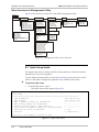
4.2 Navigating the Management Menus
This section provides a general description of the software menu operation and
conventions for navigating the menus.
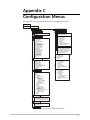
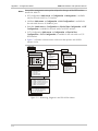
Appendix C shows a map of the management menus in the ASMi-52 embedded
software.
Choosing Options
To choose an option (terminal session):
•
Type the number corresponding to the option, and press <Enter>.
The screen for the selected option is displayed.
Note
When a menu option has only two values, typing the option number and pressing
<Enter> will scroll between the available values.
Some of the ASMi-52 menus have a 'Save' option. When choosing options from these
menus, you must confirm your choice by typing the number corresponding to the
'Save' option, otherwise your entry will be ignored.
To choose an option (ConfiguRAD session):
1. Click a link in the ConfiguRAD screen to display the next menu.
2. Once the target screen is displayed, select a value from the drop-down box.
Correcting Entries
To correct an erroneous entry:
•
Press <Backspace> to clear the error, then enter the correct characters.
or
Press <Esc> to exit the current menu, and then return to the menu to re-enter
the required value.
Navigating Data Forms
Some of the ASMi-52 management software screens are data forms, which are
bigger than regular menus and require scrolling to navigate between parameters.
For example, the Inventory screen (Figure 4-7) or Manager List menu (Figure 4-11)
are considered data forms.
Use the following keys (case-sensitive) for the data form navigation:
Note
4-4
•
L – move left, l – scroll left,
•
R – move right, r – scroll right
•
U – move up, u – scroll up
•
D – move down, d – scroll down
•
<Tab> – select next changeable cell.
You can display these navigation keys by typing <?> from a data form.
Navigating the Management Menus
ASMi-52 Installation and Operation Manual
Chapter 4 Managing ASMi-52 via a Terminal
Navigating the ConfiguRAD Menus
ConfiguRAD is a Web-based remote access terminal management software. It
provides a user-friendly interface for configuring, collecting statistics and performing
diagnostic tests on the ASMi-52 units.
To choose an option:
1. Click a link in the ConfiguRAD screen to display the next menu.
2. Once the target screen is displayed, select a value from the drop-down box or
enter it in a text box.
Some of the ASMi-52 menus have a 'Save' option. When choosing options from
these menus, you must confirm your choice by selecting 'Save', otherwise your entry
will be ignored.
At the left-hand bottom corner ConfiguRAD provides some auxiliary management
tools:
•
Status – shows the number of users currently managing ASMi-52
•
Trace – opens an additional pane for system messages, progress indicators (ping,
software and configuration file downloads) and alarms. It is recommended to
keep the trace pane open all the time.
•
Refresh All – refreshes performance registers.
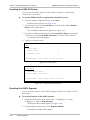
Logging Out
To end the current session:
•
Note
In the Main menu, click Logout or type & in a terminal management screen.
ASMi-52 allows only one management session to be active at a time. If the
Web-based management session was not ended properly (for example, by closing the
Web browser window), you have to wait five minutes before attempting the next login. If you try to log in during the five-minute security timeout, ASMi-52 does not
allow to proceed to the Main menu, displaying ‘Too Many Users’ message. Likewise,
the Web-based management session cannot be initiated, if a terminal or Telnet
session is still in progress.
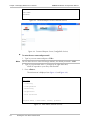
4.3 Entering the User Name and Password
Once you have installed the ASMi-52 modems at the central and remote locations,
and completed the installation and operation procedures described in Chapter 2
and Chapter 3, you can start a control session.
You have to enter a user name and password in order to start the ASMi-52
management software (see Figure 4-3 and Figure 4-4).
Entering the User Name and Password
4-5
ASMi-52 Installation and Operation Manual
Chapter 4 Managing ASMi-52 via a Terminal
ASMi-52
USER NAME:
PASSWORD:
Figure 4-3. Password Request Screen (Terminal Session)
Figure 4-4. Password Request Screen (ConfiguRAD Session)
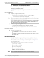
To enter the user name and password:
1. Type in your user name and press <Tab>.
Note
You can leave the user name field empty (default), the default password is 1234.
2. Type in your password at the > prompt (up to eight characters).
ASMi-52 responds to your entry with asterisks.
3. Press <Enter>.
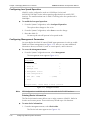
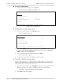
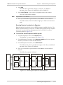
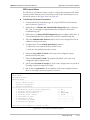
The Main menu is displayed (see Figure 4-5 and Figure 4-6).
ASMi-52
Main Menu
1. Inventory
2. Configuration
3. Monitoring
4. Diagnostics
5. File Utilities
>
ESC-prev.menu; !-main menu; &-exit; @-scroll
Figure 4-5. Main Menu (Terminal Session)
4-6
Entering the User Name and Password
ASMi-52 Installation and Operation Manual
Chapter 4 Managing ASMi-52 via a Terminal
ASMi-52
Main menu
ConfiguRAD
utilities
Figure 4-6. Main Menu (ConfiguRAD Session)
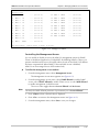
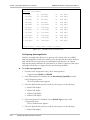
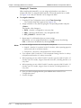
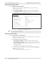
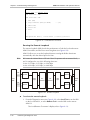
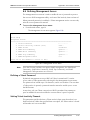
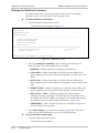
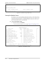
4.4 Displaying the ASMi-52 Inventory
The ASMi-52 inventory displays information on the functional blocks of the local or
remote modem.
ASMi-52 consists of the following components:
•
SHDSL unit
•
DTE unit
•
Terminal control port
•
10/100BASE-T port
•
Alarm relay port
•
Power supply.
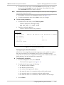
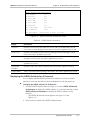
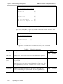
To display the ASMi-52 inventory:
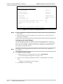
1. From the Main menu, select Inventory.
The Inventory screen appears (see Figure 4-7).
2. Use the following keys to move around the indexs.
•
L – move left, l – scroll left,
•
R – move right, r – scroll right
•
U – move up, u – scroll up
•
D – move down, d – scroll down
•
<Tab> – select next changeable cell.
Displaying the ASMi-52 Inventory
4-7
ASMi-52 Installation and Operation Manual
Chapter 4 Managing ASMi-52 via a Terminal
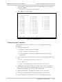
ASMi-52
Inventory
1
Index
1001
Description
RAD-local ASMi-52_M shdsl modem
Vendor type
Contained in
0
Class
3
Rel pos
0
Name
shdsl modem
HW ver
0.00
SW ver
1.00E54
->>
>
ESC-prev.menu; !-main menu; &-exit; @-scroll; ?-help
Figure 4-7. Inventory Screen
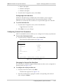
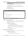
4.5 Configuring ASMi-52 System Parameters
This section describes the procedures for configuring system parameters of
ASMi-52.
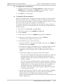
To access the Configuration menu:
•
From the Main menu, select Configuration.
The Configuration menu appears (see Figure 4-8).
ASMi-52
Configuration >
1. System configuration >
2. Physical ports configuration >
>
ESC-prev.menu; !-main menu; &-exit; @-scroll
Figure 4-8. Configuration Menu
The ASMi-52 management software allows you to perform the following:
• Configuring master clock
4-8
•
Enabling or disabling low speed operation
•
Defining management parameters (IP parameters, system information etc)
•
Configuring 10/100Base-T port
•
Defining control port parameters
•
Resetting ASMi-52 to the defaults
•
Performing the overall reset of the device or resetting its SHDSL interface.
Configuring ASMi-52 System Parameters
ASMi-52 Installation and Operation Manual
Chapter 4 Managing ASMi-52 via a Terminal
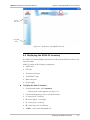
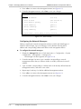
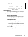
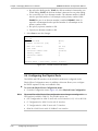
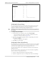
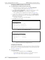
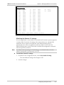
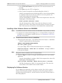
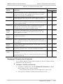
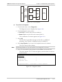
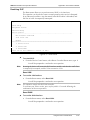
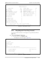
To display the System Configuration menu:
• From the Configuration menu, select System Configuration.
The System Configuration menu appears (see Figure 4-9).
ASMi-52
System Configuration >
1. Master clock
>(Internal)
2. Low Speed Operation
(No)
3. Management
>
4. LAN Configuration
>
5. Control port
>
6. Factory default
>
7. Reset
>
8. Save
>
ESC-prev.menu; !-main menu; &-exit; @-scroll
Figure 4-9. System Configuration Menu
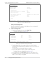
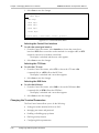
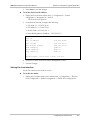
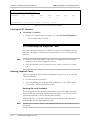
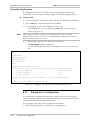
Configuring the Master Clock
ASMi-52 modems support receive, external and internal clock modes.
When configured to the internal or external clock, ASMi-52 modem operates as an
STU-C unit. When configured to the receive clock, ASMi-52 operates as an STU-R
unit.
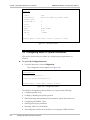
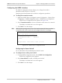
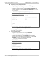
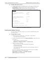
To configure the master clock:
1. From the System Configuration menu, select Master Clock.
The Master Clock menu appears (see Figure 4-10).
2. From the Master Clock menu, select the appropriate clock by choosing Receive,
Internal, or External.
The System Configuration menu returns.
3. From the System Configuration menu, select Save to save the changes.
ASMi-52
Master clock (Internal)
1. Receive
2. Internal
3. External
>
ESC-prev.menu; !-main menu; &-exit; @-scroll
Figure 4-10. Master Clock Menu
Configuring ASMi-52 System Parameters
4-9
ASMi-52 Installation and Operation Manual
Chapter 4 Managing ASMi-52 via a Terminal
Configuring Low Speed Operation
ASMi-52 can be configured to work at 64/128 kbps (2-wire) and
64/128/192/256 kbps (4-wire) when operating opposite devices with E1 DTE
interface. The maximum data rate of ASMi-52 working in the low speed mode is
2048 kbps.
To enable the low speed operation:
1. From the System Configuration, select Low Speed Operation.
The option value changes to Yes or No.
2. From the System Configuration, select Save to save the change
3. Reset the ASMi-52.
On start up the unit will operate in low speed mode.
Configuring Management Parameters
You must define the ASMi-52 internal SNMP agent parameters in order to enable
SNMP and Telnet management (see Figure 4-11). Also you can enter additional
information about your ASMi-52, such as contact person, unit location etc.
To access the Management menu:
•
From the System Configuration menu, select Management.
The Management menu appears (Figure 4-11).
ASMi-52
Management
1. Device Info
>
2. Host IP
>
3. Manager List
>
4. Management access
>
5. DTS Configuration
>
6. MTU (64 - 1540)
...(1540)
7. Save
>
ESC-prev.menu; !-main menu; &-exit; @-scroll
Figure 4-11. Management Menu
Note
DTS Configuration is available only for the units with the E1/T1 DTE interfaces.
Entering Device Information
The Device Information menu allows you to assign a name to ASMi-52, define its
location and contact person. These entries may include up to 20 characters.
To enter device information:
1. From the Management menu, select Device Info.
The Device Info menu appears (see Figure 4-12).
4-10
Configuring ASMi-52 System Parameters
ASMi-52 Installation and Operation Manual
Chapter 4 Managing ASMi-52 via a Terminal
2. From the Device Info menu, select Sys Contact and enter name of a contact
person; select Sys Location and enter description of the ASMi-52 location;
select Sys Name and enter a name of the unit.
Note
Information entered into the Sys Name field appears at the top of the configuration
screens after the product name.
3. Press <Esc> to return to the Management menu (see Figure 4-11).
4. From the Management menu, select Save to save your changes.
To clear system parameters:
1. From the Device Info menu, select Clear sys param.
ASMi-52 displays the following message:
Are you sure !!! Clear (Y/N)
2. Type Y to confirm the deletion.
ASMi-52 deletes all device info parameters.
ASMi-52
Device Info
Sys description
ASMi-52
HW Version: 0.00, SW Version: 1.00E54)
1. Sys contact
()
2. Sys location
()
3. Sys name
(ASMi-52)
4. Clear sys params
>
ESC-prev.menu; !-main menu; &-exit; @-scroll
Figure 4-12. Device Information Menu
Configuring the Host Parameters
ASMi-52 can be managed by a network management station, which is located on
the LAN connected to the 10/100BaseT port. In order to establish a proper
connection, it is necessary to configure the following: host IP address, subnet mask,
default gateway, its trap, read and write communities.
To define the IP parameters:
1. From the Management menu, select Host IP.
The Host IP menu appears (see Figure 4-13).
2. From the Host IP menu, type the following:
1 to define the host IP address
2 to define the subnet mask
3 to set the default gateway IP address
4 to enter the name of a community with read-only authorization
5 to enter the name of a community with write authorization
6 to enter the name of a community to which ASMi-52 will send traps.
3. Press <Enter>.
Configuring ASMi-52 System Parameters
4-11
ASMi-52 Installation and Operation Manual
Chapter 4 Managing ASMi-52 via a Terminal
4. Press <Esc> to return to the Management menu (see Figure 4-11).
5. From the Management menu, select Save to save your changes.
ASMi-52
Host IP
1. Host IP address
(0.0.0.0)
2. Host IP mask
(255.255.255.0)
3. Host default gateway
(0.0.0.0)
4. Read community
(public)
5. Write community
(public)
6. Trap community
(public)
>
ESC-prev.menu; !-main menu; &-exit; @-scroll
Figure 4-13. Host IP Menu
Configuring the Network Managers
Define or modify the network management stations to which the SNMP agent of
ASMi-52 will send traps. Up to ten managers can be defined. Entering the IP
address and corresponding subnet mask defines each management station.
To configure the network managers:
1. Display the Manager List menu. (Path: Main menu > Configuration > System
Configuration > Management > Manager List)
The Manager List menu appears (see Figure 4-14).
2. From the Manager List menu, type a number corresponding to network
management station that you intent to define or modify, and enter its new IP
address.
3. Type a number corresponding to a subnet mask of the already defined network
management station, and enter a new value.
4. Repeat step 2 and step 3 to define additional management stations.
5. Press <Esc> to return to the Management menu (see Figure 4-11).
6. From the Management menu, select Save to save your changes.
4-12
Configuring ASMi-52 System Parameters
ASMi-52 Installation and Operation Manual
Chapter 4 Managing ASMi-52 via a Terminal
ASMi-52
Manager List
1. MNG 1
IP
... (0.0.0.0)
12. MNG 2
MASK
... (0.0.0.0)
2. MNG 2
IP
... (0.0.0.0)
13. MNG 3
MASK
... (0.0.0.0)
3. MNG 3
IP
... (0.0.0.0)
14. MNG 4
MASK
... (0.0.0.0)
4. MNG 4
IP
... (0.0.0.0)
15. MNG 5
MASK
... (0.0.0.0)
5. MNG 5
IP
... (0.0.0.0)
16. MNG 6
MASK
... (0.0.0.0)
6. MNG 6
IP
... (0.0.0.0)
17. MNG 7
MASK
... (0.0.0.0)
7. MNG 7
IP
... (0.0.0.0)
18. MNG 8
MASK
... (0.0.0.0)
8. MNG 8
IP
... (0.0.0.0)
19. MNG 9
MASK
... (0.0.0.0)
9. MNG 9
IP
... (0.0.0.0)
20. MNG 10 MASK
... (0.0.0.0)
10. MNG 10 IP
... (0.0.0.0)
11. MNG 1
>
... (0.0.0.0)
MASK
ESC-prev.menu; !-main menu; &-exit; @-scroll
Figure 4-14. Manager List Menu
Controlling the Management Access
You can enable or disable access to the ASMi-52 management system via SNMP,
Telnet or Web-based application (ConfiguRAD). By disabling SNMP or Telnet, you
prevent unauthorized access to the system when security of the ASMi-52 IP address
has been compromised. When SNMP, Telnet and Web access is disabled,
ASMi-52 can be managed via an ASCII terminal only.
To define the management access method:
1. From the Management menu, select Management Access.
The Management Access menu appears (see Figure 4-15).
2. From the Management Access menu, select SNMP Allowed to enable SNMP
access, select TELNET Allowed to enable Telnet access, or select WEB Allowed
to enable management via Web browser.
The access value toggles between Access Allowed and No Access.
Note
Currently the SNMP Allowed parameter is permanently set to Access Allowed.
3. Press <Enter> when a desired value is displayed.
4. Press <Esc> to return to the Management menu (see Figure 4-11).
5. From the Management menu, select Save to save your changes.
Configuring ASMi-52 System Parameters
4-13
ASMi-52 Installation and Operation Manual
Chapter 4 Managing ASMi-52 via a Terminal
ASMi-52
Management Access
1. SNMP allowed
(access allowed)
2. TELNET allowed
(access allowed)
3. WEB allowed
(access allowed)
>
ESC-prev.menu; !-main menu; &-exit; @-scroll
Figure 4-15. Management Access Menu
Configuring Dedicated Timeslots
ASMi-52 units with E1 or T1 port support management via a dedicated timeslot.
A remote E1 device can be managed via DTS if the DTS mode is enabled in both
the CO unit and the CPE unit. The MNG timeslot is transferred over the SHDSL to
the E1 CPE, the CPE forwards the MNG timeslot over the E1 line to the next device
in the chain.
Note
Allocate the same timeslot number for MNG in all devices in the chain. With DTS
mode enabled in all devices, then the chain can be managed remotely from one NMS.
In T1 systems, the DTS is manages the local unit only, it is not forwarded over SHDSL.
To configure dedicated timeslots:
1. From the Management menu, select DTS Configuration.
The DTS Configuration menu is displayed (see Figure 4-16).
2. From the DTS Configuration menu, configure the dedicated timeslot in the
following order:
Assign DTS IP address
Assign DTS IP mask
Enable DTS mode.
3. Check the status of the DTS configuration in the Rem Agent Table (see Figure 4-17).
4. From the Management menu, select Save to save the changes.
In the Map Timeslot menu (Figure 4-38), the dedicated timeslot value
changes to MNG (management).
ASMi-52
DTS Configuration
1. DTS Mode
(Enable)
2. DTS IP Address
(1.1.1.1)
3. DTS IP Mask
(255.255.255.0)
4. Rem Agent Table
[]>
>
ESC-prev.menu; !-main menu; &-exit; @-scroll
Figure 4-16. DTS Configuration Menu
4-14
Configuring ASMi-52 System Parameters
ASMi-52 Installation and Operation Manual
Chapter 4 Managing ASMi-52 via a Terminal
ASMi-52
Rem Agent Table
SOURCE IP
DESTINATION IP
PORT
172.17.161.30
255.255.255.255
DTS
172.17.161.34
224.0.0.9
DSL
172.17.161.182
224.0.0.9
DSL
172.17.160.104
172.17.161.186
DTS
>
ESC-prev.menu; !-main menu; &-exit; @-scroll; ?-help
Figure 4-17. Rem Agent Table
Configuring the LAN Port
ASMi-52 includes a 10/100BaseT port that can be used as a user or management
port. The LAN port operates in a self-learning bridge or transparent mode, with or
without autonegotiation.
Note
If the LAN port serves as a management port only, it operates in transparent mode
with autonegotiation enabled.
Configuring LAN Port Operation Mode
In the transparent mode the LAN port operates with disabled filter, passing all
frames transparently. When operating as a self-learning bridge, the LAN port filters
the packets received from the local LAN and transfers through the link only frames
destined to another LAN.
To configure the LAN operation mode:
1. From the System Configuration menu, select LAN Configuration.
The LAN Configuration menu appears (see Figure 4-18).
2. From the LAN Configuration menu, select Operation Mode.
The Operation Mode menu appears.
3. From the Operation Mode menu, select Transparent to enable transparent
mode, or select Bridge to enable bridge mode.
Note
Currently for the units with the serial, E1 or T1 DTE interfaces the Operation Mode is
permanently set to Transparent. For the modems with the 10/100BaseT user LAN
interface it is set to Bridge.
The LAN Configuration menu appears.
4. From the LAN Configuration menu, select Save to save your changes.
Configuring ASMi-52 System Parameters
4-15
ASMi-52 Installation and Operation Manual
Chapter 4 Managing ASMi-52 via a Terminal
ASMi-52
LAN Configuration
Operation Mode
(Bridge)
Bridging Mode
(Switching)
1. Bridge Table
[]>
2. Aging Timeout(sec)[10 - 1000000]
(10)
3. Auto negotiation
(Enable)
4. Max AutoNeg Capability
(100BASE_T-full duplex mode)
5. Fault indication
(Yes)
6. LAN rate
(2304)
7. Save
>
ESC-prev.menu; !-main menu; &-exit; @-scroll
Figure 4-18. LAN Configuration Menu
Filling out the Bridge Table
When the 10/100BaseT port operates in the bridge mode, you can assign MAC
addresses to the local or remote LAN.
To fill out the bridge table:
1. From the LAN Configuration menu, select Bridge Table.
The Bridge Table appears (see Figure 4-19).
ASMi-52
Bridge Table
MAC Address
1. 0010b340500
Port
LAN
Type
Static
2. 0040e108070
DSL
Static
3. 00000000000
Static
>
ESC-prev.menu; !-main menu; &-exit; ?-help
Figure 4-19. Bridge Static Table, Normal Mode
2. From the Bridge Table, select an empty cell (the one with MAC address
0000000000 and unassigned port) by typing D to move the cursor down or U
to move it up.
You can also select an existing MAC address to reassign it.
3. Once the MAC address is selected, type m to enable editing mode.
The Bridge Table enters editing mode (see Figure 4-20).
4. In the editing mode, select MAC Address and enter a MAC address value.
5. Select Port and assign the current MAC address to the local LAN by entering
LAN or to remote LAN by entering DSL.
4-16
Configuring ASMi-52 System Parameters
ASMi-52 Installation and Operation Manual
Chapter 4 Managing ASMi-52 via a Terminal
6. Select Save All to save the changes.
7. Press <Esc> to exit the editing mode.
To remove MAC address from the table:
1. From the Bridge Table, select MAC address that you intend to remove from the
static table.
2. Enter editing mode, as explained above.
3. Enter all zeros for the MAC address value and save the change.
ASMi-52
Bridge Table
1.
Type
(Static)
MAC Address ... (00000000000)
2.
Port
... ()
>
ESC-prev.menu; !-main menu; &-exit; ?-help
Figure 4-20. Bridge Table, Editing Mode
Configuring Aging Timeout
The aging time is the timeout period in seconds for aging out dynamically learned
forwarding information. When the timeout period is over, the bridge removes all
inactive nodes from its database.
To configure aging timeout:
1. From the LAN Configuration menu, select Aging Timeout.
2. Enter a new aging timeout value in seconds and press <Enter>.
3. Select Save to save the change.
Setting the LAN Rate
When the LAN port of ASMi-52 is used for the DTE connection, the DTE rate is
configured via the LAN rate menu. The LAN rate depends on the rate mode (regular
or low speed, see Configuring Low Speed Operation above) and the line interface
(2-wire or 4-wire).
Note
ASMi-52 units operating in the receive clock mode automatically detect LAN rate of
the central units and configure themselves accordingly.
To set the LAN rate:
1. From the LAN Configuration menu, select LAN Rate.
The LAN Rate menu appears (see Figure 4-21).
2. From the LAN Rate menu, select the desired data rate.
The LAN Configuration menu appears.
3. From the LAN Configuration menu, select Save to save the new value.
Configuring ASMi-52 System Parameters
4-17
ASMi-52 Installation and Operation Manual
Chapter 4 Managing ASMi-52 via a Terminal
ASMi-52
Data Rate (2304 Kbps)
1. 64 Kbps
12.
768 Kbps
23.
1472 Kbps
2. 128 Kbps
13.
832 Kbps
24.
1536 Kbps
3. 192 Kbps
14.
896 Kbps
25.
1600 Kbps
4. 256 Kbps
15.
960 Kbps
26.
1664 Kbps
5. 320 Kbps
16.
1024 Kbps
27.
1728 Kbps
6. 384 Kbps
17.
1088 Kbps
28.
1792 Kbps
7. 448 Kbps
18.
1152 Kbps
29.
1856 Kbps
8. 512 Kbps
19.
1216 Kbps
30.
1920 Kbps
9. 576 Kbps
20.
1280 Kbps
31.
1984 Kbps
10. 640 Kbps
21.
1344 Kbps
32.
2048 Kbps
11. 704 Kbps
22.
1408 Kbps
33.
2304 Kbps
>
ESC-prev.menu; !-main menu; &-exit; @-scroll
Figure 4-21. LAN Rate Menu (2-WireVersion)
Configuring Autonegotiation
ASMi-52 autonegotiation allows you to operate at the fastest data rate available.
With autonegotiation enabled, the ASMi-52 unit automatically determines between
itself and the DTE the fastest data rate and duplex mode that they can operate.
With autonegotiation disabled, the LAN interface of ASMi-52 operates at the speed
and duplex mode that is configured by the Max AutoNeg capability.
To set the autonegotiation:
1. From the LAN Configuration menu, select Autonegotiation.
Toggle between Enable and Disable.
2. If the autonegotiation is enabled, choose Max AutoNeg Capability from the
LAN Configuration menu.
The Set Capability menu appears.
3. Select the desired LAN operation mode by choosing one of the following:
10BaseT half duplex
10BaseT full duplex
100BaseT half duplex
100BaseT full duplex.
4. If the autonegotiation is disabled, choose Default Type from the LAN
Configuration menu.
The Set Default menu appears.
5. Select the desired LAN operation mode by choosing one of the following:
10BaseT half duplex
4-18
Configuring ASMi-52 System Parameters
ASMi-52 Installation and Operation Manual
Chapter 4 Managing ASMi-52 via a Terminal
10BaseT full duplex
100BaseT half duplex
100BaseT full duplex.
6. From the LAN Configuration menu, select Save.
Configuring Fault Indication
If ASMi-52 fault indication is enabled and a fault condition or loss of signal is
detected on the line, the Ethernet link is disconnected by ASMi-52. If fault
indication is not selected, fault conditions are not passed through to the LAN side.
To set the fault indication:
1. From the LAN Configuration menu, select fault indication.
Toggle between Yes and No.
2. Select Save to save your changes
Configuring Control Port Parameters
ASMi-52 embedded software enables you to configure the Control port parameters.
To access the Control port menu:
•
From the System Configuration menu, select Control Port.
The Control Port menu appears (see Figure 4-22)
ASMi-52
Control Port
1. Rate
>(9600)
2. Interface
(DCE)
3. CTS
(=RTS)
4. DSR
(DTR)
5. Port Control
>
6. Save
>
ESC-prev.menu; !-main menu; &-exit; @-scroll
Figure 4-22. Control Port Menu
Changing the Control Port Data Rate
The control port of ASMi-52 supports different data rates that can be configured via
the Rate menu (see Figure 4-23).
To configure the control port data rate:
1. From the Control Port menu, select Rate.
The Rate menu appears (see Figure 4-23).
2. Select the terminal rate by typing the number corresponding to the desired
value, and press <Enter>.
Configuring ASMi-52 System Parameters
4-19
ASMi-52 Installation and Operation Manual
Chapter 4 Managing ASMi-52 via a Terminal
3. Select Save to save the changes.
ASMi-52
Rate (9600 kbps)
1. 9600 kbps
2. 19200 kbps
3. 38400 kbps
4. 57600 kbps
5. 115200 kbps
>
ESC-prev.menu; !-main menu; &-exit; @-scroll
Figure 4-23. Control Port Rate Menu
Selecting the Control Port Interface
To select the control port interface:
1. From the Control Port menu, select Interface to choose the control port
interface: DCE (direct connection to the terminal via a straight cable) or DTE
(terminal connection via modem or data link).
The display is refreshed and the new value appears.
2. Select Save to save the changes.
Selecting the CTS State
To select the CTS state:
1. From the Control Port menu, select CTS to choose the CTS state: ON
(constantly ON) or =RTS (follows the RTS line).
The display is refreshed and a new value appears.
2. Select Save to save the changes.
Selecting the DSR State
To select the DSR state:
1. From the Control Port menu, select DSR to choose the DSR state: ON
(constantly ON) or DTR (follows the DTR line).
The display is refreshed and a new value appears.
2. Select Save to save the changes.
Changing the Terminal Parameters
The Port Control menu allows you to do the following:
4-20
•
Setting port mode (terminal, dial out or SLIP)
•
Managing user name and password
•
Enabling or disabling pop-up alarms
•
Defining security timeout
•
Configuring dial-out parameters.
Configuring ASMi-52 System Parameters
ASMi-52 Installation and Operation Manual
Chapter 4 Managing ASMi-52 via a Terminal
To access the Port Control menu:
•
Path: Main Menu > Configuration > Control Port > Port Control.
The Port Control menu appears (see Figure 4-24).
ASMi-52
Port Control
1. Port Control Mode
> (Terminal)
2. Terminal
>
3. Dial out
>
4. Save
>
ESC-prev.menu; !-main menu; &-exit; @-scroll
Figure 4-24. Port Control Menu
Configuring Port Control Mode
CONTROL port of ASMi-52 operates in one of the following modes:
Note
•
Terminal – direct connection to the control terminal (DCE mode) or to modem
(DTE mode)
•
Dial-out – connection to dial-out modem for alarm reporting
•
SLIP – connection to management station via Serial Line Internet Protocol.
Currently connection to ASMi-52 via SLIP is disabled.
To configure port control mode:
1. From the Port Control menu, select Port Control.
The Port Control Mode menu appears (see Figure 4-25).
ASMi-52
Port Control Mode (Terminal)
1. Terminal
2. Dial out
3. SLIP
>
ESC-prev.menu; !-main menu; &-exit; @-scroll
Figure 4-25. Port Control Mode Menu
2. From the Port Control Mode menu, select desired operation mode.
The Port Control menu appears.
3. From the Port Control menu, select Save to save the change.
Configuring User Name, Password, Pop-up Alarms and Security
Timeout
User name, password, pop-up alarms and security timeout are configured via
Terminal menu.
Configuring ASMi-52 System Parameters
4-21
ASMi-52 Installation and Operation Manual
Chapter 4 Managing ASMi-52 via a Terminal
To access Terminal menu:
•
From the Port Control menu, select Terminal.
The Terminal menu appears (see Figure 4-26).
ASMi-52
Terminal
1. Change access
>
2. POP ALARM
(OFF)
3. Security timeout
(10 min)
4. Save
>
ESC-prev.menu; !-main menu; &-exit; @-scroll
Figure 4-26. Terminal Menu
To change the user name and password:
1. From the Terminal menu, select Change Access.
The following dialog appears:
ASMi-52
Change Access
1. User name
...()
2. Password ...
3. Clear User Name
...
4. Clear Password
>
...
ESC-prev.menu; !-main menu; &-exit; @-scroll
2. Select User Name to enter a new user name, select Password to enter a new
password, select Clear User Name to delete the current user, or Clear User
Name to delete the current password.
3. Enter a new user name or password and press <Enter>.
The Terminal menu appears.
4. From the Terminal menu, select Save to save the changes.
To enable or disable the pop-up alarms:
When the pop-up function is enabled, ASMi-52 displays the active alarms at the
bottom of the terminal screen. When the fault condition that caused the alarm is
cleared, the alarm is removed from the screen
1. From the Terminal menu, select Pop Alarm to choose the pop-up alarms mode:
ON (pop-up alarms are enabled) or OFF (pop-up alarms are disabled).
The display is refreshed and the new value appears.
2. Select Save to save the changes.
4-22
Configuring ASMi-52 System Parameters
ASMi-52 Installation and Operation Manual
Chapter 4 Managing ASMi-52 via a Terminal
To configure the security timeout:
1. From the Terminal menu, select Security Timeout to configure the timeout:
FOREVER (timeout is disabled) or 10 MIN (idle disconnect time – 10 min).
The display is refreshed and a new value appears.
2. Select Save to save the changes.
To change the dial-out parameters:
When the CONTROL port is configured to the dial out mode, you must specify the
dial-out parameters of the port. This enables ASMi-52 to build the call command
that is sent to the dial-out modem. When connecting the dial-out modem, you must
use a cross cable (see Appendix A for the cross cable pinout).
The modem connected to the CONTROL connector must be set up as follows (for
convenience, the Hayes commands required to select the specified parameters are
listed in brackets):
• Auto-answer mode (AT S0=1 and AT S1=1)
•
Call set up in response to the CONNECT string (AT X0)
•
No echo (AT E0)
•
Verbose mode (no codes, e.g., CONNECT string instead of 0) (AT V1).
1. From the Port Control menu (see Figure 4-24), select Dial out.
The Dial Out menu appears (see Figure 4-27).
2. From the Dial Out menu, type the following:
1 to instruct ASMi-52 to report all alarms (ALL), only major ones (MAJOR), or
disable alarm reporting (NONE).
2 to specify the number of dialing retries. 0, no redialing attempts are made
if the call is not established on the first attempt. 1–8, if the call is not
established on the first attempt, ASMi-52 makes the specified number of
redials.
This parameter applies to both primary and alternate numbers:
If the call is not established after dialing the primary directory number the
specified number of times, ASMi-52 attempts to establish the call by
dialing the alternate directory number (provided the use of an alternate
number is enabled).
If the call cannot be established within the specified number of redialing
attempts on neither of the two directory numbers, ASMi-52 stops the call
attempts. When a new alarm report must be sent, the call attempts are
started again. The user is notified that the call attempts failed by a
message recorded in the alarm log file (separate messages are provided
for each directory number).
3 to specify the time (in sec) ASMi-52 waits for an answer after each dialing
attempt. If the called station does not answer within the specified time,
ASMi-52 disconnects. If additional call attempts are allowed,
ASMi-52 redials immediately after disconnecting. The available selections are
30, 45, or 60 seconds.
Configuring ASMi-52 System Parameters
4-23
Chapter 4 Managing ASMi-52 via a Terminal
ASMi-52 Installation and Operation Manual
4 to select the dialing mode. TONE, the dial-out modem is instructed to use
DTMF dialing. PULSE, the dial-out modem is instructed to use pulse dialing.
5 to control the use of an alternate number. The alternate number is dialed
after the specified number of call attempts on the primary number failed.
ENABLE, the use of an alternate number is enabled. DISABLE, ASMi-52
stops the call attempts after the specified number of call attempts on the
primary number failed.
6 to specify a primary number to dial.
7 specify an alternate number to dial.
3. Select Save to save the changes.
ASMi-52
Dial out
1. Call Out Mode
(None)
2. Number of Retries [0-8]
(1)
3. Wait for connect
(30 sec)
4. Dial mode
(Tone)
5. Alternate number mode
(Disable)
6. Primary number
()
7. Alternate number
()
8. Save
>
ESC-prev.menu; !-main menu; &-exit; @-scroll
Figure 4-27. Control Port Dial Out Menu
4.6 Configuring the Physical Ports
The SHDSL and DTE interfaces of the ASMi-52 modem are configured via the
Physical Ports Configuration menu. In addition, this menu allows you to configure
the SHDSL repeaters (if they are installed in line).
To access the Physical Ports Configuration menu:
•
Note
4-24
From the Configuration menu (Figure 4-8), select Physical Ports Configuration.
The second line of the Physical Port configuration menu changes according to the
DTE interface installed in ASMi-52. The possible options are:
• DTE Configuration for ASMi-52 units with a serial interface (V.35, X.21 or RS-530)
•
E1 Configuration for ASMi-52 units with E1 interface
•
T1 Configuration for ASMi-52 units with T1 interface
•
Blank for ASMi-52 units with 10/100BaseT user interface.
Configuring the Physical Ports
ASMi-52 Installation and Operation Manual
Chapter 4 Managing ASMi-52 via a Terminal
Configuring the SHDSL Interface
The ASMi-52 configuration software allows you to change the modem’s
transmission mode (Annex A or Annex B).
Examples given below illustrate the local device configuration procedures.
To change the transmission mode:
1. Display the SHDSL Device Configuration menu (Configuration > Physical Ports
Configuration > SHDSL Configuration menu > SHDSL Device Configuration).
SHDSL Device Configuration menu appears (see Figure 4-28).
2. Select Transmission Mode to choose transmission mode: Annex A or Annex B.
The display is refreshed and a new value appears.
3. Select Save to save the changes.
Note
ASMi-52 units operating in the receive clock mode automatically detect standard
compatibility value of the central units and configure themselves accordingly.
ASMi-52
SHDSL local device configuration
1. Transmission mode :
(Annex B)
2. Save
>
ESC-prev.menu; !-main menu; &-exit; @-scroll
Figure 4-28. SHDSL Device Configuration Menu
Configuring the Power Backoff
You can determine if the transmitted power backoff is used.
To configure the use of the power backoff:
1. From the SHDSL Configuration menu, select SHDSL Port Configuration.
SHDSL Port Configuration menu appears.
2. Select Power backoff to enable or disable power backoff.
The display is refreshed and a new value appears.
3. Select Save to save the changes.
Configuring the Physical Ports
4-25
ASMi-52 Installation and Operation Manual
Chapter 4 Managing ASMi-52 via a Terminal
ASMi-52
SHDSL local port configuration
1. Power backoff
(Enable)
2. Snext margin
(Disable)
3. Current margin
(Disable)
4. Asym PSD
(Symmetrical)
5. Line prob
(Adaptive rate)
6. Configured wire
(2W)
7. Loop attenuation threshold (dB) [0-127]
(0)
8. SNR margin threshold (dB) [0-15]
(0)
9. Save
>
ESC-prev.menu; !-main menu; &-exit; @-scroll
Figure 4-29. SHDSL Port Configuration Menu
Notes
• After changing the Configured Wire option, ASMi-52 must be reset to implement
the change.
• When operating in Line prob. Adaptive rate, and the clock is internal, the rate is
limited up to 2048 bps.
Configuring the Snext Margin
The Snext margin indicates the minimum desired target margin with a worst-case
self next noise model given current loop insertion (49 SHDSL next is considered the
worst case). This setting is available only if the rate adaptation is enabled (see the
line probing configuration below).
Note
Disabling the Snext margin parameter allows the use of all line rates, regardless of
line condition.
To configure the Snext margin:
1. From the SHDSL Port Configuration menu, select Snext margin.
The Snext Margin menu appears (see Figure 4-30).
2. Select the Snext margin by typing the number corresponding to the desired
value.
SHDSL Port Configuration menu appears.
3. Select Save to save the changes.
4-26
Configuring the Physical Ports
ASMi-52 Installation and Operation Manual
Chapter 4 Managing ASMi-52 via a Terminal
ASMi-52
Snext margin (Disable Snext margin)
1.
-10
12.
1
2.
-9
13.
2
3.
-8
14.
3
4.
-7
15.
4
5.
-6
16.
5
6.
-5
17.
6
7.
-4
18.
7
8.
-3
19.
8
9.
-2
20.
9
10. -1
21.
10
11. 0
22.
Disable Snext margin
>
ESC-prev.menu; !-main menu; &-exit; @-scroll
Figure 4-30. Snext Margin Menu
Configuring the Current Margin
The current margin indicates the minimum desired target margin for the local line
conditions during the startup sequence. This setting is available only if the rate
adaptation is enabled (see the line probing configuration below).
Note
Disabling the current margin parameter allows the use of all line rates, regardless of
line condition.
To configure the current margin:
1. From the SHDSL Port Configuration menu, select Current margin.
The Current Margin menu appears. The display is identical to the Snext
Margin menu, except for its title (see Figure 4-30).
2. Select the current margin by typing the number corresponding to the desired
value, and press <Enter>.
SHDSL Port Configuration menu appears.
3. Select Save to save the changes.
Configuring the Power Spectral Density
By configuring the power spectral density, you define the amount of power applied
to the spectrum of frequencies that carry the information signal in order to achieve
a satisfactory level of signal strength at the receiving end of the circuit.
The power spectral density can be configured for the ASMi-52 units with the line
probing set to fixed.
The power spectral density value depends on the selected modems compatibility:
Annex A or Annex B. The possible values are:
•
Symmetric, supported in both Annex A and Annex B modes.
•
Asymmetric, supported in Annex A at 768 kbps and in Annex B at 2048 kbps.
Configuring the Physical Ports
4-27
Chapter 4 Managing ASMi-52 via a Terminal
ASMi-52 Installation and Operation Manual
To configure the power spectral density:
1. From the SHDSL Port Configuration menu, select Asym PSD to choose the
power spectral density value: symmetrical or asymmetrical.
The display is refreshed and a new value appears.
2. Select Save to save the changes.
Note
Remote ASMi-52 units automatically detect the line power density. This parameter is
permanently set to Sym/Asym Enable and cannot be changed.
Configuring the Line Probing
By configuring this parameter, you force ASMi-52 to perform line probing in order
to find the best possible rate of transmission – adaptive rate. Or you command the
modem to skip the rate adaptation phase – fixed rate.
Only central ASMi-52 units with the 2-wire line interface support fixed and adaptive
rates, remote units operate with adaptive rate only.
ASMi-52 units with the 4-wire line interface support only fixed rate.
To configure the line probing:
1. From the SHDSL Port Configuration menu, select Line Prob.
The display is refreshed and a new value appears.
2. Select Save to save the changes.
Configuring the Line Interface Type
You can configure the ASMi-52 units with 4-wire interface to operate over 2-wire
lines. Selecting the 2-wire operation mode disables pin 1 and pin 2 of the RJ-45 line
connector.
To configure the line interface type for ASMi-52 units:
1. From the SHDSL Port Configuration menu, select Configured wire
The display is refreshed and a new value appears (2W or 4W).
2. Select Save to save the changes
3. Reset ASMi-52 in order to active the change.
Setting the Loop Attenuation Threshold
Loop attenuation is difference (in dB) between the power transmitted from the
ASMi-52 modem and the power received by the unit operating at the other side of
the application. By setting the threshold, you instruct the modem to generate minor
alarm (LOOP ATTN. OVER LINE A/B), if selected loop attenuation threshold value is
exceeded.
To set the loop attenuation threshold:
1. From the SHDSL Port Configuration menu, select Loop attenuation threshold.
2. Enter the desired value (0 dB to 127 dB).
3. Select Save to save the changes.
4-28
Configuring the Physical Ports
ASMi-52 Installation and Operation Manual
Chapter 4 Managing ASMi-52 via a Terminal
Setting the SNR Margin Threshold
You can set signal-to-noise ratio threshold. ASMi-52 generates minor alarm (SNR
MARGIN OVER LINE A/B), if the signal-to-noise ratio on the line exceeds the
threshold value.
To set the SNR margin threshold:
1. From the SHDSL Port Configuration menu, select SNR margin threshold.
2. Enter the desired value (0 dB to 15 dB).
3. Select Save to save the changes.
Configuring the SHDSL Repeater
Configuration parameters of the SHDSL repeaters are similar to those of the SHDSL
device, except for the following:
•
Selecting repeater that you intend to configure
•
Selecting power backoff for the customer and network sides of the repeater.
The SHDSL repeaters are configured via the SHDSL Repeater Configuration menu.
To access the SHDSL Repeater Configuration menu:
•
From the SHDSL Configuration menu (Configuration > Physical Ports
Configuration > SHDSL Configuration menu), select SHDSL repeater
configuration.
The SHDSL Repeater Configuration menu is displayed (see Figure 4-31).
ASMi-52
SHDSL repeater configuration
1. Power backoff Network side
(Disable)
2. Power backoff Customer side
(Disable)
3. Loop Attenuation threshold (dB)[0 - 127]
(0)
4. SNR margin threshold (dB)[0 – 15]
(0)
5. Repeater number
>
(1)
6. Save
>
ESC-prev.menu; !-main menu; &-exit; @-scroll
Figure 4-31. SHDSL Repeater Configuration Menu
Configuring the Serial DTE Interface
If the ASMi-52 modem is equipped with a serial data interface, the configuration
software allows you to enable/disable the LLB/RLB activation from the DTE (except
for X.21) and select the modem’s data rate.
Configuring the Physical Ports
4-29
ASMi-52 Installation and Operation Manual
Chapter 4 Managing ASMi-52 via a Terminal
Configuring LLB/RLB Activation from the DTE
To enable/disable the LLB/RLB activation from the DTE:
1. From the Physical Ports Configuration menu, select DTE Configuration.
The DTE Configuration menu appears (see Figure 4-32).
2. Select DTE local port configuration to configure the local DTE port or select
DTE remote port configuration for the remote port configuration.
DTE Local/Remote Port Configuration menu appears (see Figure 4-33).
3. From the DTE Local/Remote Port Configuration menu, select LLB from DTE to
enable the LLB activation from the DTE or select RLB from DTE to enable the
RLB activation from the DTE.
The display is refreshed and a new value appears.
4. Select Save to save the changes.
ASMi-52
DTE configuration >
Port number:
(1)
1. DTE local port configuration
2. DTE remote port configuration
>
ESC-prev.menu; !-main menu; &-exit; @-scroll
Figure 4-32. DTE Configuration Menu
ASMi-52
DTE local port configuration >
1. LLB from DTE :
(Disable)
2. RLB from DTE :
(Disable)
3. Data rate > >
(192 Kbps)
4. Save
>
ESC-prev.menu; !-main menu; &-exit; @-scroll
Figure 4-33. DTE Local Port Configuration Menu
Configuring the Data Rate
ASMi-52 supports multiple data rates in the range between 64 kbps and 4608 kbps,
depending on the clock mode and line/DTE interface of the local and remote units
(see Table 1-2 and Table 1-3).
To select the data rate:
1. From the DTE Port Configuration menu, select Data Rate.
The Data Rate menu appears (see Figure 4-34). The ASMi-52 screen in
Figure 4-34 is with a 2-wire, internal clock configuration.
4-30
Configuring the Physical Ports
ASMi-52 Installation and Operation Manual
Chapter 4 Managing ASMi-52 via a Terminal
2. Select the data rate by typing the number corresponding to the desired value,
and press <Enter>.
The DTE Port Configuration menu appears.
3. Select Save to save the changes.
ASMi-52
Data Rate (384 Kbps)
1. 64 Kbps
13.
2. 128 Kbps
14.
3. 192 Kbps
15.
4. 256 Kbps
16.
5. 320 Kbps
17.
6. 384 Kbps
18.
7. 448 Kbps
19.
8. 512 Kbps
20.
9. 576 Kbps
21.
10. 640 Kbps
22.
11. 704 Kbps
23.
12. 768 Kbps
24.
832 Kbps
896 Kbps
960 Kbps
1024 Kbps
1088 Kbps
1152 Kbps
1216 Kbps
1280 Kbps
1344 Kbps
1408 Kbps
1472 Kbps
1536 Kbps
25.
26.
27.
28.
29.
30.
31.
32.
33.
1600
1664
1728
1792
1856
1920
1984
2048
2304
Kbps
Kbps
Kbps
Kbps
Kbps
Kbps
Kbps
Kbps
Kbps
>
ESC-prev.menu; !-main menu; &-exit; @-scroll
Figure 4-34. Data Rate Menu
Configuring the E1 Interface
When ASMi-52 includes a G.704 E1 port, you can configure the following
parameters:
•
Selecting framing mode
Unframed – Stream of bits at 2.048 Mbps
G732N – Timeslot 0 contains sync word
G732S transparent – 16 frames per multiframe, timeslot 16 is passed
transparently.
•
Selecting time required for the E1port to return to normal operation after sync
loss:
CCITT – As per requirements of ITU-T Rec.G.732
Fast – After 1 sec
62411 – As per requirements of AT&T TR-62411 (after 10 sec).
•
Enabling generation and checking of check bits for the frames transmitted on
the E1 port (as per CRC-4 polynomial specified by ITU G.704). Check bits
generation is available only for the G732N framing mode.
•
Mapping E1 timeslots – Assigning each timeslot to carry user’s data.
•
Selecting a code transmitted to fill unused timeslots in the E1 frames.
The E1 port configuration is performed via the E1 Port Configuration menu.
Configuring the Physical Ports
4-31
ASMi-52 Installation and Operation Manual
Chapter 4 Managing ASMi-52 via a Terminal
To access the E1 Port Configuration menu:
1. From the Physical Ports Configuration menu, select E1 Configuration.
The E1 Configuration menu appears.
2. From the E1 Configuration menu, select E1 local port configuration for the
local port configuration or select E1 remote port configuration for the remote
port configuration.
The E1 Port Configuration menu appears (see Figure 4-35).
ASMi-52
E1 Local Port Configuration
1. Framed mode
(G732N)
2. Sync mode
(CCITT(complies with G732))
3. CRC-4
(NO)
4. Idle code
(ff)
5. Time slots assign
6. Units identical setting
(Yes)
7. Save
>
ESC-prev.menu; !-main menu; &-exit; @-scroll
Figure 4-35. E1 Port Configuration Menu
Selecting E1 Framing Mode
To select E1 framing mode:
1. From the E1 Port Configuration menu, select Framed Mode.
The Framed Mode menu appears (see Figure 4-36).
2. From the Framed Mode menu, select Unframed to choose unframed
operation, type G732N to select G732N framing mode, or select G732S
transparent to choose G732S transparent framing mode.
The E1 Port Configuration menu appears.
3. Save the changes.
ASMi-52
Framed mode (Unframed)
1. Unframed
2. G732N
3. G732S transparent
>
ESC-prev.menu; !-main menu; &-exit; @-scroll
Figure 4-36. Framed Mode Menu
4-32
Configuring the Physical Ports
ASMi-52 Installation and Operation Manual
Chapter 4 Managing ASMi-52 via a Terminal
Selecting Resynchronization Time
You can define time required for the E1 port operating in the framed mode to
normal operation after loss of synchronization:
• CCITT – As per requirements of ITU-T Rec.G.732
•
Fast – After 1 sec
•
62411 – As per requirements of AT&T TR-62411 (after 10 sec).
To select resynchronization time:
1. From the E1 Port Configuration menu, select Sync Mode.
The Sync Mode menu appears (see Figure 4-37).
2. From the Sync Mode menu, select CCITT to choose CCITT mode, select FAST
to choose FAST mode, or select 62411 to choose 62411 mode.
The E1 Port Configuration menu appears.
3. Save the changes.
ASMi-52
Sync mode (CCITT (complies with G732))
1. CCITT (complies with G732)
2. FAST (after 1 sec)
3. 62411 (after 10 sec)
>
ESC-prev.menu; !-main menu; &-exit; @-scroll
Figure 4-37. Sync Mode Menu
Enabling CRC-4 Code Generation
You have to enable the CRC-4 code generation if you intend to gather statistics on
the E1 performance. CRC-4 code generation is available for ASMi-52 units
configured to G732N framing mode.
To enable CRC-4 code generation:
1. From the E1 Port Configuration menu, select CRC-4.
The CRC-4 value changes.
2. Save the changes.
Defining Idle Code
You can define the code transmitted to fill idle (unused) timeslot in the E1 frames.
To define idle code:
1. From the E1 Port Configuration menu, select Idle Code
2. Enter desired code in the range of 00 to FF, press <Enter>.
3. Save the changes.
Configuring the Physical Ports
4-33
Chapter 4 Managing ASMi-52 via a Terminal
ASMi-52 Installation and Operation Manual
Mapping E1 Timeslots
When working with framed E1, you can assign each timeslot to carry data or
transmit idle code. To assign the MNG timeslot, DTS mode must be set to enable
(see Figure 4-16). Only one timeslot can be assigned to MNG.
To assign E1 timeslots:
1. From the E1 Port Configuration menu, select Time slots assign.
The Timeslots Map menu appears (see Figure 4-38).
2. Assign a timeslot to carry data by typing the corresponding number and press
<Enter>.
The timeslot value changes to:
DATA – timeslot is configured to carry user data
MNG – timeslot is dedicated to carry management traffic
NOT_CONNECT – timeslot is idle.
3. Repeat step 2 for all timeslots that you want to assign.
Alternatively, you can assign all timeslots to carry data at once by selecting
FULL, or disconnect all timeslots by selecting CLEAR.
Notes
•
You can configure timeslot 0 to be looped or transparent:
Looped – timeslot 0 is sent back to the E1 interface, when operating opposite
remote units with a serial data interface.
Transparent – timeslot 0 is transmitted to the remote modem.
•
If you operate ASMi-52 with the G732S transparent framing, timeslot 0 is always
transparent and timeslot 16 is always connected.
•
When operating a 2-wire ASMi-52 with E1 interface opposite ASMi-52 with V.35
interface (not in LS mode), assign at least three timeslots, excluding timeslot 0, to
carry data.
•
When operating a 4-wire ASMi-52 with E1 interface opposite ASMi-52 with V.35
interface (not in LS mode), assign at least six timeslots, excluding timeslot 0, to
carry data.
4. Once you finish assigning timeslots, press <Esc> return to the E1 Port
Configuration menu.
5. Save the changes.
4-34
Configuring the Physical Ports
ASMi-52 Installation and Operation Manual
Time slot
1. TS0
2. TS1
3. TS2
4. TS3
5. TS4
6. TS5
7. TS6
8. TS7
9. TS8
10. TS9
11. TS10
12. TS11
13. TS12
14. TS13
15. TS14
16. TS15
map
TRANS
MNG
DATA
DATA
DATA
DATA
DATA
DATA
DATA
DATA
DATA
DATA
DATA
DATA
DATA
DATA
Chapter 4 Managing ASMi-52 via a Terminal
ASMi-52
17.
18.
19.
20.
21.
22.
23.
24.
25.
26.
27.
28.
29.
30.
31.
32.
TS16
TS17
TS18
TS19
TS20
TS21
TS22
TS23
TS24
TS25
TS26
TS27
TS28
TS29
TS30
TS31
DATA
DATA
DATA
DATA
DATA
DATA
DATA
DATA
DATA
DATA
DATA
DATA
DATA
DATA
DATA
DATA
33.
34.
FULL
CLEAR
ESC-prev.menu; !-main menu; &-exit; @-scroll
Figure 4-38. Map Timeslot Menu
Matching the Remote E1 Settings
If in your application a central ASMi-52 unit with the E1 interface operates opposite
a remote ASMi-52 unit, the E1 settings of the remote device are automatically
matched to those of the local modem (the Units Identical Setting value is
permanently set to YES). For applications with two ASMi-52 units, the Units
Identical Setting value of the local modem overrides the management commands
from the supervisory terminal.
Note
For ASMi-52 units operating in G732S framing or in unframed mode, the Units
Identical Setting value is permanently set to YES.
To match the remote E1 settings:
1. From the E1 Port Configuration menu, select Units Identical Setting.
The Units Identical Setting value changes to YES.
2. Save the changes.
Configuring the Physical Ports
4-35
Chapter 4 Managing ASMi-52 via a Terminal
ASMi-52 Installation and Operation Manual
Configuring the T1 Interface
ASMi-52 units with T1 interface require configuration of the following parameters:
•
Framing mode:
Unframed – Stream of bits at 1.544 Mbps
ESF – 24 frames per multiframe
SF – 12 frames per multiframe
•
Line coding:
B8ZS – B8ZS coding
AMI – AMI coding
•
Receive gain (sensitivity of the receive equalizer):
Long – -36 dB
Short – 15 dB
•
Interface:
DSU – DSU interface
CSU – CSU interface
•
Transmit signal mask (DSU mode) – length of a cable in feet between the
ASMi-52 T1 port connector and the network access point:
0 feet – 0 to 133 ft
133 feet – 133 to 266 ft
266 feet – 266 to 399 ft
399 feet – 399 to 533 ft
533 feet – 533 to 655 ft.
•
Transmit signal mask (CSU mode) – relative T1 output transmit level:
7.5 dB – attenuation of 7.5 dB relative to the nominal transmit level)
15 dB – attenuation of 15 dB relative to the nominal transmit level)
22.5 dB – attenuation of 22.5 dB relative to the nominal transmit level)
•
Fbit configuration – F-bit transmission mode:
Transparent – F bits are sampled at TSER
Internally Source – F bits are sourced internally.
Note
Configuration of the sync mode, idle code, timeslot assignment and matching of T1
setting of the local and remote units is identical of that of the E1 interface. Refer to
Configuring the E1 Interface section above.
To access the T1 Configuration menu:
1. From the Physical Ports Configuration menu, select T1 Configuration.
The T1 Configuration menu appears.
2. From the T1 Configuration menu, select T1 local port configuration for the
local port configuration or select T1 remote port configuration for the remote
port configuration.
4-36
Configuring the Physical Ports
ASMi-52 Installation and Operation Manual
Chapter 4 Managing ASMi-52 via a Terminal
The T1 Port Configuration menu appears (see Figure 4-39).
ASMi-52
T1 Local Port Configuration
1. Framed Mode
2. Line Code
3. Receive Gain
4. Interface
5. Fbit Configuration
6. Sync Mode
7. Idle code
8. Time slots assign
9. Units identical setting
10.
Save
>(UNFRAMED)
(B8ZS)
(LONG)
>
(Transparent)
> (FAST (after 1 sec))
(ff)
>
(Yes)
>
ESC-prev.menu; !-main menu; &-exit; @-scroll
Figure 4-39. T1 Port Configuration
4.7 Displaying the ASMi-52 Status
The ASMi-52 software allows you to display the modem system and physical port
information.
The status information is available via the Monitoring menu.
To access the Monitoring menu:
•
From the Main menu, select Monitoring.
The Monitoring menu appears (see Figure 4-40).
ASMi-52
Monitoring
1. Total Alarms
2. System monitoring
3. Physical ports monitoring
4. Open Virtual Connection
[]>
>
>
>
ESC-prev.menu; !-main menu; &-exit;
Figure 4-40. Monitoring Menu
Displaying the ASMi-52 Status
4-37
ASMi-52 Installation and Operation Manual
Chapter 4 Managing ASMi-52 via a Terminal
Displaying the System Status
To display the system information:
1. Display the system status menu. (Path: Monitoring >System monitoring >
System local/remote status)
2. Select System local status to display the local device status information or
select System remote status to display the remote device status information.
The System Status screen appears (see Figure 4-41).
ASMi-52
System Status
Device Type
(ASMi-52_M (PLASTIC) - STU_C-2W)
Clock Source
(INT)
Software Version
(1.00E54)
Hardware Version
(0.00)
FPGA Version
(0.05)
Hardware Status
(NO HARDWARE FAILURE)
PS
(WIDE RANGE)
MAC address
(0 00 10 40 00 0)
IP address
(1.1.1.1)
Alarm Indication
(MAJOR)
Test Indication
(OFF)
>
ESC-prev.menu; !-main menu; &-exit;
Figure 4-41. System Status Screen
Note
Alarms are described in Chapter 5.
Displaying the Port Status
To display the port status information:
1. Display the Physical Port Status menu. (Path: Monitoring menu > Physical Port
Monitoring > Physical Port Status)
2. From the Physical Port Status menu select:
Physical Port Local Status to display the local port status information
Physical Port Remote Status to display the remote port status information
Physical Port Repeater Status to display repeater alarms (see Chapter 5 for a
detailed description).
The Physical Port Local/Remote Status menu appears.
3. From the Physical Port Local/Remote Status menu, select Port Local/Remote
Status to display the port status.
The Port Status screen appears (see Figure 4-42).
4-38
Displaying the ASMi-52 Status
ASMi-52 Installation and Operation Manual
Chapter 4 Managing ASMi-52 via a Terminal
ASMi-52
Port local status
SHDSL
(Standard ANNEX UNKNOWN, Wire mode 2W)
SHDSL Line
(Status: NOT SYNC, State: IDLE mode)
Framer Type
(SLOTTED T1)
EOC compatible
(STANDARD)
Actual PSD
(PSD UNKNOWN)
Line rate
(not applicable)
T1 interface
(IR-G704/BALANCE Data rate: 1536 kbps)
HW status
(NO HARDWARE FAILURE)
Test status
(NONE)>
(N)
ESC-prev.menu; !-main menu; &-exit;
Figure 4-42. Port Status Screen
Note
The physical port alarms are described in Chapter 5.
4. Type N to display the next page.
4.8 Accessing the Remote ASMi-52
Accessing the remote ASMi-52 is performed using a virtual connection with your
terminal physically connected to the local unit.
To access the remote ASMi-52
1. From the Monitoring menu (Figure 4-40), select Open Virtual Connection
2. The Login screen of the second ASMi-52 appears.
3. Login to the second ASMi-52
You now have access to the second ASMi-52 menus.
Note
If no key press is sensed for a period of 10 minutes, the virtual connection closes and
you are returned to the initial ASMi-52.
To close a virtual terminal
•
From the Monitoring menu (of the second ASMi-52), select Close Virtual
Connection
The Main menu of the first ASMi-52 is displayed.
Accessing the Remote ASMi-52
4-39
ASMi-52 Installation and Operation Manual
Chapter 4 Managing ASMi-52 via a Terminal
4.9 Updating Software Releases
This section presents procedures for installing new software releases into the
ASMi-52 units, as well as swapping existing software versions in a local or remote
unit.
ASMi-52 stores two software versions, each of them in one of the two 512-byte
partitions of its flash memory, which also contains a boot program. The software is
stored in compressed format. The active version is decompressed and loaded into
the ASMi-52 RAM upon power-up. The passive software is kept for the backup
purposes. By default, ASMi-52 is delivered with the active software only.
The new software releases are distributed on diskettes as an *.img file, which is
downloaded to the local ASMi-52 using the TFTP or XMODEM protocol. Upon
downloading, the new software release becomes active, the former active software
turns into backup, and the former backup is erased.
If a failure occurs during downloading or decompression, the new version is erased
from the flash and the backup version becomes active. In this case, only one version
is left stored in the flash memory. If active software becomes corrupted, you can
replace it with the backup one.
Installing a New Software Release via TFTP
To install a new software release via TFTP:
1. Display the TFTP menu (Figure 4-43) (Main menu > File Utilities S&W & File
Transfer > TFTP)
TFTP
TFTP status
TFTP error
1. TFTP IP server
2. TFTP file name
3. TFTP retry timeout
4. TFTP total timeout
5. Save
6. Transfer command
>
ASMi-52
(No operation)
(No error)
(0.0.0.0)
(asmi52.img)
(15)
(60)
ESC - prev. menu ; ! – main menu ; & – exit
Figure 4-43. TFTP Menu
2. From the TFTP menu, perform the following steps:
Select TFTP IP Server and enter the IP address of the TFTP server
Select TFTP File Name and enter the name of the software file (for example,
asmi52.img).
Select TFTP Retry Timeout and specify intervals between connection retries
(in seconds).
4-40
Updating Software Releases
ASMi-52 Installation and Operation Manual
Chapter 4 Managing ASMi-52 via a Terminal
Select TFTP Total Timeout and specify the TFTP connection timeout (in
seconds).
Select Save to save the TFTP configuration.
Select Transfer Command to start downloading file to ASMi-52.
ASMi-52 automatically erases the backup partition. Once the downloading
is completed, ASMi-52 saves the new release as an active partition, the
former active partition becomes backup.
Once the downloading is complete, ASMi-52 decompresses the release file,
displaying the following message:
Final process download. Reset
After the decompression, ASMi-52 saves the new release as an active
partition, the former active partition becomes backup. Then the unit resets
itself. This causes the new software to be loaded into the modem's RAM.
Installing a New Software Release via XMODEM
Notes
• Installation of the new software releases via XMODEM is not possible over Telnet.
• To minimize the software downloading time, it is recommended to configure the
CONTROL port to the highest available data rate, see Changing the Control Port
Data Rate section above.
To install a new software release via XMODEM:
1. Follow the path: Main menu > File Utilities S&W & File Transfer > XMODEM.
ASMi-52 responds with the following string:
PLEASE OPEN XMODEM APPLICATION.
For exit press Q(uit)
If you press <Q>, ASMi-52 aborts the download process and displays
Download failure. Press Esc to continue. message in addition
to the previous display.
Note
During the software installation, the TST indicator blinks.
2. Send the *.img file to ASMi-52 using the XMODEM protocol of your terminal
application.
Once the downloading is complete, ASMi-52 decompresses the release file,
displaying the following message:
Final process download. Reset device after 5 seconds
After the decompression, ASMi-52 is automatically reset. This causes the
new software to be loaded into the modem's RAM.
Displaying the Software Version
You can display the information on the software revision of the local or remote
modem. The information includes a description of the active program, which is
currently being used by ASMi-52, and also details on the passive software kept for
the backup purposes.
Updating Software Releases
4-41
Chapter 4 Managing ASMi-52 via a Terminal
ASMi-52 Installation and Operation Manual
To display the software version:
1. From the SW Files menu, (File Utilities menu > File System > SW files), select
Local SW Files to display software revision of the local ASMi-52, or select
Remote SW Files to display software revision of the remote device.
The Local or Remote Software Version screen appears (see Figure 4-44).
SW files
Software active version:
Software active partition:
Code size:
Date:
1.00A05
0
683027
17-7-3
Software backup version:
Software backup partition:
Code size:
Date:
0.00n00
1
0
0-0-0
Boot version:
Boot mng version:
1.20
6.00
Press any key to continue...
ESC-prev.menu; !-main menu; &-exit
Figure 4-44. Local Software Version Screen
Switching the Software Versions
If an active software becomes corrupted, you can switch it with the backup in the
local ASMi-52 units.
To swap software versions:
1. Follow the path: File Utilities menu > File System > Swap SW files.
The Swap SW Files menu appears.
2. From the Swap SW Files menu, select Swap Local SW Files to switch files in the
local ASMi-52.
ASMi-52 displays the following message:
Request to swap SW files!!! Confirm Y/N
3. Type Y to confirm the file swap.
ASMi-52 performs the swap and sends the following string:
Program Switching
Active software becomes backup and vice versa. At this stage, ASMi-52 is
automatically reset.
If you try to switch the software versions when only one version is available,
ASMi-52 responds with the following message:
Impossible to switch – no other program
Press any key to continue
4-42
Updating Software Releases
ASMi-52 Installation and Operation Manual
4.10
Chapter 4 Managing ASMi-52 via a Terminal
Resetting ASMi-52
ASMi-52 supports four types of reset:
• Reset to the default setting
•
SHDSL interface reset
•
SHDSL repeater line reset.
•
Overall reset
Resetting to Default Settings
You can reset the local or remote ASMi-52 to default settings. Resetting to the
factory default does not affect the master clock setting. In addition, you can reset
the local ASMi-52 without affecting its management parameters (IP address, mask
and default gateway).
To reset ASMi-52 to the factory default:
1. Display the Factory Default menu. (Path: Main menu > Configuration >
System Configuration > Factory default)
Factory Default menu is displayed (Figure 4-45).
ASMi-52
Factory default
1. Local factory default
...
2. Remote factory default
...
3. Local factory default W/O MNG ...
4. Remote factory default W/O MNG ...
>
ESC - prev. menu ; ! – main menu ; & – exit
Figure 4-45. Factory Default Menu
2. From the Factory Default menu, perform one the following steps:
Select Local Factory Default to reset the local ASMi-52.
Select Remote Factory Default to reset remote device.
Select Local Factory Default W/O MNG to reset all parameters, except for
IP address, mask, default gateway and manager list of the local ASMi-52.
Select Remote Factory Default W/O MNG to reset all parameters, except
for IP address, mask, default gateway and manager list of the remote
ASMi-52.
Note
Local/Remote Factory Default W/O MNG parameters are available only for the units
equipped with the management LAN port.
ASMi-52 displays the following message:
Request to factory default !!! Confirm Y/N
3. Type Y to confirm the reset.
ASMi-52 resets all configuration parameters, except for the master clock
(and IP values), to their default settings and restarts the system.
Resetting ASMi-52
4-43
ASMi-52 Installation and Operation Manual
Chapter 4 Managing ASMi-52 via a Terminal
Resetting the ASMi-52 Modem
You can reset the SHDSL interface of the modem or repeater, or perform the
overall reset of the modem.
To reset the SHDSL interface or perform the overall device reset:
1. From the System Configuration menu, select Reset.
The Reset menu appears (see Figure 4-46).
2. From the Reset menu, select Local Reset to reset the local modem, Remote
Reset to reset remote device.
The Local/Remote Reset menu appears (see Figure 4-47).
3. From the Local/Remote Reset menu, select Local Device Reset to perform the
overall reset or select Local SHDSL Line Reset to reset the SHDSL interface.
A confirmation message appears.
4. Type Y to confirm the reset.
ASMi-52
Reset
1. Local reset
>
2. Remote reset
>
3. Repeater reset
>
>
ESC-prev.menu; !-main menu; &-exit; @-scroll
Figure 4-46. Reset Menu
ASMi-52
Local Reset
1. Local device reset
2. Local SHDSL line reset
>
ESC-prev.menu; !-main menu; &-exit; @-scroll
Figure 4-47. Local/Remote Reset Menu
Resetting the SHDSL Repeater
You can reset line interface of the SHDSL repeater from the local ASMi-52 via the
Reset menu.
To reset line interface of the SHDSL repeater:
1. Display the Reset menu. (Path: Main menu > Configuration > System
configuration > Reset > Repeater Reset)
The Repeater Reset menu appears (see Figure 4-48).
2. From the Repeater Reset menu, select Repeater Number.
The Repeater Number menu appears.
4-44
Resetting ASMi-52
ASMi-52 Installation and Operation Manual
Chapter 4 Managing ASMi-52 via a Terminal
3. From the Repeater Number menu, select repeater that you intend to reset.
4. From the Repeater Reset menu, select Repeater SHDSL Line Reset to reset the
SHDSL line interface of the repeater.
A confirmation message appears.
5. Type Y to confirm the reset.
ASMi-52
Repeater Reset
1. Repeater SHDSL line reset...
2. Repeater number
>
(1)
>
ESC-prev.menu; !-main menu; &-exit; @-scroll
Figure 4-48. Repeater Reset Menu
4.11
Exiting the Control Session
You can exit the terminal control session at any time by typing & + Enter from any
management menu.
The software returns to the login screen.
Exiting the Control Session
4-45
Chapter 4 Managing ASMi-52 via a Terminal
4-46
Exiting the Control Session
ASMi-52 Installation and Operation Manual
Chapter 5
Configuring a Typical
Application
5.1 Overview
This chapter provides detailed instructions for setting up two ASMi-52 modems in
a typical application.
Configuration of ASMi-52 is performed via menu-driven embedded software,
using a standard ASCII terminal or a PC running a terminal emulation application
connected to the rear panel CONTROL port. Alternatively, ASMi-52 can be
managed from a Telnet host connected to the 10/100BASE-T port on the rear
panel. Read Chapter 4 to familiarize yourself with operation from a terminal.
Application
Two ASMi-52 modems operating opposite each other. One in the central office,
the second the customer premises equipment. User traffic is E1 unframed.
ASCII
Terminal
E1
Unframed
Router
CO
CPE
ASMi-52
Internal Clock
123.456.78.90
ASMi-52
Receive Clock
123.456.78.91
E1
Unframed
Router
Figure 5-1. Typical ASMi-52 Application
Guidelines for Configuring ASMi-52 Units
Each ASMi-52 unit must be configured individually. This typical application has the
following configuration steps:
1. Setting the system: Setting the clock mode and the device Host IP address
2. Setting the line interface: Setting the Wire mode (2W or 4W)
3. Setting the E1 port: Setting the framing mode.
Overview
5-1
ASMi-52 Installation and Operation Manual
Chapter 5 Configuring a Typical Application
5.2 Configuring the ASMi-52 units
Two ASMi-52 units must be configured for this application. Both units have the
same configuration parameters, except for the host IP address and the master clock
mode.
To prepare a control session:
1. Connect the terminal cable to the CONTROL connector of ASMi-52.
2. Turn the control terminal on.
3. Configure the terminal to the default communication parameters: 9.6 kbps,
one start bit, eight data bits, no parity, one stop bit, VT100 emulation.
4. Select the full duplex mode.
5. Turn the terminal echo off.
6. Disable any type of flow control.
You are now ready to start a control session.
To enter the user name and password:
1. Type in your user name and press <Tab>.
Note
You can leave the user name field empty (default), the default password is 1234.
2. Type in your password at the > prompt (up to eight characters).
ASMi-52 responds to your entry with asterisks.
3. Press <Enter>.
The Main menu is displayed.
Setting the ASMi-52 System
To configure the master clock.
1. Display the Master Clock menu (Main menu > Configuration > System
configuration > Master Clock)
The Master Clock menu appears.
ASMi-52
Master clock (Internal)
Receive
Internal
External
>
ESC-prev.menu; !-main menu; &-exit; @-scroll
2. From the Master Clock menu, three clock modes are given Receive, Internal,
or External.
Set the CO ASMi-52 unit clock to Internal
Set the CPE ASMi-52 unit clock to Receive
5-2
Configuring the ASMi-52 units
ASMi-52 Installation and Operation Manual
Chapter 5 Configuring a Typical Application
3. Select Save to save the changes.
To set the device host IP address:
4. Display the host IP menu (Main menu > Configuration > System
configuration > Management > Host IP.
The host IP screen appears.
5. From the host IP menu, configure the following:
CO ASMi-52 – 123.456.78.90
CPE ASMi-52 – 123.456.78.91
Host IP mask – 255.255.255.1
Host default gateway IP address – 255.255.255.2
ASMi-52
Host IP
Host IP address
Host IP mask
Host default gateway
Read community
Write community
Trap community
(123.456.78.90)
(255.255.255.1)
(255.255.255.2)
(public)
(public)
(public)
>
ESC-prev.menu; !-main menu; &-exit; @-scroll
6. Press ESC to return to previous menu (Management screen).
7. Save the changes.
Setting the Line Interface
Set the line interface wire mode to 4-wire.
To set the wire mode:
1. Display the Configured wire screen (Main menu > Configuration > Physical
Ports Configuration > SHDSL Configuration > SHDSL Port Configuration).
Configuring the ASMi-52 units
5-3
ASMi-52 Installation and Operation Manual
Chapter 5 Configuring a Typical Application
ASMi-52
SHDSL local port configuration
1. Power backoff
2. Snext margin
3. Current margin
4. Asym PSD
5. Line prob
6. Configured wire
7. Loop attenuation threshold (dB) [0-127]
8. SNR margin threshold (dB) [0-15]
9. Save
>
ESC-prev.menu; !-main menu; &-exit; @-scroll
(Enable)
(Disable)
(Disable)
(Symmetrical)
(Adaptive rate)
(4W)
(0)
(0)
2. Select Configured wire
The display is refreshed and a new value appears (4W).
3. Select Save to save the change
4. Reset ASMi-52 in order to activate the change.
Setting the E1 port
To select E1 framing mode:
1. Display the Framed Mode screen (Main menu > Configuration > Physical
Ports Configuration > E1 Port Configuration menu > Framed Mode)
The Framed Mode menu appears.
ASMi-52
Framed mode (Unframed)
1. Unframed
2. G732N
3. G732S transparent
>
ESC-prev.menu; !-main menu; &-exit; @-scroll
2. From the Framed Mode menu, select Unframed to choose unframed
operation.
The E1 Port Configuration menu appears.
3. Save the changes.
After performing these configuration procedures, the ASMi-52 units are ready to
be connected.
5-4
Configuring the ASMi-52 units
Chapter 6
Troubleshooting and
Diagnostics
This chapter describes the ASMi-52 diagnostic functions, which include:
•
Status indications, alarms, power-up self-test
•
Statistics collection
•
Diagnostic tests (loopbacks and LEDs test).
6.1 Error Detection
Power-Up Self-Test
ASMi-52 performs a hardware self-test upon turn-on. The self-test sequence
checks the critical circuit functions of the modem.
The results of the hardware self-test for the local or remote ASMi-52 are displayed
in the System Status and Physical Status Port screens (see Chapter 4).
Front Panel LEDs
The status of ASMi-52 is indicated by the ALM, TST and SYNC LED indicators
located on the front panel. For the description of LEDs and their functions, refer to
Chapter 3.
Displaying Alarms
ASMi-52 detects fault conditions and initiates alarms to alert the user. ASMi-52
supports the following alarm types:
•
System alarms, relating to the ASMi-52 chassis
•
Port alarms, relating to a specific interface (SHDSL or DTE)
•
Information messages (warnings)
•
Events that trigger alarm activation.
ASMi-52 maintains two separate displays for the system and port alarms. In
addition, the modem supports a local log file, holding up to 100 alarms.
An alarm or warning enters simultaneously both the alarms display and the log file,
and the ALM LED turns on to indicate the condition. When the fault condition that
caused the alarm is cleared, the alarm is removed from the alarm screen, but it
Error Detection
6-1
ASMi-52 Installation and Operation Manual
Chapter 6 Troubleshooting and Diagnostics
remains in the log file, enabling you to view the alarm history. Events enter only
the log file.
Displaying All Alarms
ASMi-52 allows you to display all alarms, irrespective of their origin (system or
port).
To display all alarms:
1. From the Main menu, select Monitoring.
The Monitoring menu appears (see Figure 6-1).
2. From the Monitoring menu, select Total Alarms.
The Total Alarms Screen appears (see Figure 6-2).
The display of the alarms screen includes the source of alarm (local or remote
device), name of the alarm, its number, severity (major or minor) and status
(always ON), see Figure 6-2.
Once the event that caused the alarm is cleared, the ALM indicator turns off.
3. Press <Enter> to refresh the display.
ASMi-52
Monitoring
1. Total alarms
>
2. System monitoring
>
3. Physical ports monitoring
[]>
>
ESC-prev.menu; !-main menu; &-exit; @-scroll
Figure 6-1. Monitoring Menu
ASMi-52
Total alarms
Source
Local 1
Local 1
Name
PSD NOT COMPATIBLE
CRC ERROR OVER LINE A
Num
16
21
Figure 6-2. Total Alarms Screen
6-2
Error Detection
Severity
MINOR
MINOR
Status
ON
ON
ASMi-52 Installation and Operation Manual
Chapter 6 Troubleshooting and Diagnostics
Displaying System Alarms
To display the system alarms:
1. From the Main menu, select Monitoring.
2. From the Monitoring menu, select System Monitoring.
The SystemMonitoring menu appears (see Figure 6-3).
3. Select Device Local Alarms to display the local device alarms or type Device
Remote Alarms to display the remote device alarms.
The Device Alarms screen appears (see Figure 6-4).
ASMi-52
System Monitoring
System local status
>
System remote status
>
Device local alarms
[]>
Device remote alarms
[]>
System log file
System clear log file
...
>
ESC-prev.menu; !-main menu; &-exit; @-scroll
Figure 6-3. System Monitoring Menu
ASMi-52
Device local alarms
Source
Local 1
Alarm name
SELF TEST ERROR
Alarm num
1
Severity
MAJOR
Status
ON
Figure 6-4. Device Alarms Screen
Working With System Log File
ASMi-52 maintains system alarm buffer, which can store up to 100 system alarm
messages. The system log file specifies alarm or event name, severity (major or
minor), status (ON or OFF), and time elapsed since the last ASMi-52 reset.
To display the system log file:
•
From the System Monitoring menu (Figure 6-3), select System Log File.
The System Log File screen appears.
To clear the system log file:
1. From the System Monitoring menu (Figure 6-3), select System Clear Log File
to clear the log file.
A confirmation message is displayed at the bottom of the screen.
Error Detection
6-3
ASMi-52 Installation and Operation Manual
Chapter 6 Troubleshooting and Diagnostics
2. Type Y and press <Enter>.
All the system log file entries are deleted from the log file.
Displaying Port Alarms
1. Follow the path: Main menu > Monitoring > Physical Port Monitoring >
Physical Port Status
The Physical Port Status menu appears.
2. From the Physical Port Status menu, select:
Physical Port Local Statistics to display the local port status
Physical Port Remote Statistics to display the remote port status
Physical Port Repeater Status to display the SHDSL repeater alarms.
3. From the Physical Port Local/Remote Status menu, select Port Local/Remote
Alarms to display the local or remote port alarms.
The Port Alarms screen appears (see Figure 6-6).
ASMi-52
Physical port local status
1. Port local status
2. Port local alarms
3. Line mask
(NO_MASK)
4. Port log file
5. Port clear log file
>
ESC-prev.menu; !-main menu; &-exit; @-scroll
Figure 6-5. Physical Port Status Menu
ASMI 52
Port local alarms
Source
Local 1
Alarm name
E1 SIGNAL LOSS
Alarm num
27
Severity
MAJOR
Status
ON
Figure 6-6. Port Alarms Screen
Masking Port Alarms
ASMi-52 allows you to mask alarms generated by local and remote devices.
To mask ASMi-52 alarms:
•
From the Physical Port Local Status menu (Figure 6-5), select Line mask.
The Line Mask value changes to Mask. ASMi-52 starts ignoring all alarms
generated devices connected to the modem.
Working With Port Log File
ASMi-52 maintains port alarm buffer, which can store up to 100 alarm messages.
The port log file specifies alarm or event name, severity (major or minor), status
(ON or OFF), and time elapsed since the last ASMi-52 reset.
6-4
Error Detection
ASMi-52 Installation and Operation Manual
Chapter 6 Troubleshooting and Diagnostics
To display the log file:
1. From the Monitoring menu, select Physical Ports Monitoring.
The Physical Ports Monitoring menu appears.
2. Select Physical Port Local Status to display the local port status or select
Physical Port Remote Status to display the remote port status.
The Physical Port Local/Remote Status menu appears (see Figure 6-5).
3. From the Physical Port Local/Remote Status menu, select Port Log File.
The Port Log File screen appears (see Figure 6-7).
ASMI 52
Port log file
Source Name
1 Local MNGMNT IS DOWN
2
Local SYNC LOSS LINE A
severity
MAJOR
Status
ON
time
: 0:0:0
MAJOR
ON
: 0:0:1
ESC-prev.menu; !-main menu; &-exit; @-scroll; ?-help
1 user(s)
Figure 6-7. Port Log File Screen
To clear the log file:
1. From the Physical Port Status menu, select Port Clear Log File to clear the log
file.
A confirmation message is displayed at the bottom of the screen.
2. Type Y and press <Enter>.
All the log file entries are deleted from the log file.
Error Detection
6-5
ASMi-52 Installation and Operation Manual
Chapter 6 Troubleshooting and Diagnostics
Table 6-1. ASMi-52 Alarms and Warnings
Number
Terminal Message
Port
Description
Severity
1
SELF TEST ERROR
–
Failure occurred during self-test
Major
2
SOFTWARE
DOWNLOAD
–
Software download is in progress
Warning
4
LLB FROM DTE
DTE
Local loopback has been activated by physical
connector (units with V.35 DTE interface only)
Warning
5
RLB FROM DTE
DTE
Remote loopback has been activated by physical
connector (units with V.35 DTE interface only)
Warning
6
PROP PROT FAIL
SHDSL
FE Management by EOC failed
Warning
8
LAN NOT
CONNECTED
DTE
The Ethernet interface is not connected to LAN
Major
9
LOOP ATTN. OVER
LINE A
SHDSL
Line A loop attenuation has exceeded the alarm
threshold
Minor
10
LOOP ATTN. OVER
LINE B
SHDSL
Line B loop attenuation has exceeded the alarm
threshold (4-wire units only)
Minor
11
SNR MARGIN OVER
LINE A
SHDSL
Line A signal-to-noise margin has exceeded the
alarm threshold
Minor
12
SNR MARGIN OVER
LINE B
SHDSL
Line B signal-to-noise margin has exceeded the
alarm threshold (4-wire units only)
Minor
13
LOSW FAILURE OVER
LINE A
SHDSL
Loss of Sync Word is detected on line A
Minor
14
LOSW FAILURE OVER
LINE B
SHDSL
Loss of Sync Word is detected on line B
(4-wire units only)
Minor
15
DATA RATE NOT
COMPATIBLE
DTE
Mismatch in the line rate and data rate.
Applicable for the ASMi-52 units with V.35
interface, operating in adaptive rate mode
Major
16
PSD NOT
COMPATIBLE
SHDSL
Mismatch between PSD mode selected by the
user and PSD mode used by the line
Minor
17
SYNC LOSS LINE A
SHDSL
SHDSL line A is nor synchronized
Major
18
SYNC LOSS LINE B
SHDSL
SHDSL line B is nor synchronized
(4-wire units only)
Major
19
MNGNT IS DOWN
SHDSL
The management link between local and remote
units is down
Major
21
CRC ERROR OVER
LINE A
SHDSL
Excessive CRC-6 errors have been detected on
SHDSL line A
Minor
22
CRC ERROR OVER
LINE B
SHDSL
Excessive CRC-6 errors have been detected on
SHDSL line B (4-wire units only)
Minor
23
NO DTE INTERFACE
DTE
No DTE interface is detected
Major
25
E1 REMOTE FAILURE
DTE
Red alarm is detected at the remote E1 or T1 port
Major
T1 REMOTE FAILURE
6-6
Error Detection
ASMi-52 Installation and Operation Manual
Chapter 6 Troubleshooting and Diagnostics
Table 6-1. ASMi-52 Alarms and Warnings (Cont.)
Number
Terminal Message
Port
Description
Severity
26
E1-TS NOT RATE
COMP
DTE
Current line rate does not support the number of
assigned E1 or T1 timeslots
Major
DTE
E1 or T1 loss is detected at the DTE port
Major
DTE
E1 or T1 bipolar violation errors exceed threshold
Minor
T1-TS NOT RATE
COMP
27
E1 SIGNAL LOSS
T1 SIGNAL LOSS
28
E1 BPV ERR EXC
T1 BPV ERR EXC
29
E1 FRAME SLIP EXC
DTE
E1 frame slips exceed the threshold
Minor
30
E1 EXCECIVE BPV
DTE
Bipolar violations rate exceeds 1×10⁻⁶ during the
last 1000 seconds
Major
T1 EXCECIVE BPV
31
E1 CRC-4 EXC
DTE
CRC-4 errors exceed the threshold
Minor
32
E1 EXCESIVE ERR
RATIO
DTE
The bit error rate of the link exceeds 10-3
Major
DTE
AIS is detected at the E1 or T1 port
Major
DTE
AIS and loss of frame alignment are detected at
the E1 or T1 port
Major
DTE
E1 or T1 loss of frame synchronization occurred
Major
T1 EXCESIVE ERR
RATIO
33
E1 AIS OCCURED
T1 AIS OCCURED
34
E1 AIS AND SYNC
LOSS
T1 AIS AND SYNC
LOSS
35
E1 SYNC LOSS
T1 SYNC LOSS
36
E1 CRC MF EXC
DTE
CRC errors detected in the frame synchronization
signal exceeded the threshold
Minor
37
E1 REMOTE SYNC
LOSS
DTE
Remote loss of frame synchronization occurred
Major
T1 REMOTE SYNC
LOSS
38
E1 MF SYNC LOSS
DTE
Local loss of frame synchronization
Major
39
E1 MF REMOTE SYNC
LOSS
DTE
Remote loss of frame synchronization
Major
40
E1 TS NOT X128
DTE
Number of timeslots assigned for the ASMi-52
unit with 4-wire line interface is not n×128
Major
DTE
Number of timeslots assigned for the local unit
does not match the number of timeslots assigned
for the remote unit.
Major
T1 TS NOT X128
41
E1 TS NOT COMP
T1 TS NOT COMP
Error Detection
6-7
ASMi-52 Installation and Operation Manual
Chapter 6 Troubleshooting and Diagnostics
Table 6-1. ASMi-52 Alarms and Warnings (Cont.)
Number
Terminal Message
Port
Description
Severity
42
WIRE MODE NOT
COMP
SHDSL
Mismatch between line interface types (2/4-wire)
between local and remote units
Major
43
SPAN IS NOT FULL
SHDSL
Distance between adjacent repeaters is too long.
You can identify the problematic segment by
checking the Port Status screen. In the Number of
Repeaters line, it displays the last repeater
identified by ASMi-52. This means that the
distance between the last detected repeater and
the next repeater exceeds it maximum range.
Major
44
LOOP ATTN. OVER
NETWORK SIDE
SHDSL
Loop attenuation at the network side of the
repeater has exceeded the alarm threshold
Minor
45
LOOP ATTN. OVER
CUSTOMER SIDE
SHDSL
Loop attenuation at the customer side of the
repeater has exceeded the alarm threshold
Minor
46
SNR MARGIN OVER
NETWORK SIDE
SHDSL
Signal-to-noise margin at the network side of the
repeater has exceeded the alarm threshold
Minor
47
SNR MARGIN OVER
CUSTOMER SIDE
SHDSL
Signal-to-noise margin at the customer side of the
repeater has exceeded the alarm threshold
Minor
48
LOSW FAILURE OVER
NETWORK SIDE
SHDSL
Loss of Sync Word is detected at the network
side of the repeater
Minor
49
LOSW FAILURE OVER
CUSTOMER SIDE
SHDSL
Loss of Sync Word is detected at the customer
side of the repeater
Minor
50
LINE PARAMERS NOT
COMP
SHDSL
Modems fail to synchronize due to the
configuration parameters mismatch. For example:
Major
• The modems operate in the adaptive mode
(Line Prob is set to Adaptive Rate) and
distance between them exceeds the
maximum range.
• ASMi-52 with V.35 interface operates
opposite remote unit with E1 interface. If the
modem V.35 is set to the data rate which is
not supported by the remote unit, e.g.
2304 kbps, the units will not synchronize.
51
EXTERNAL TO
INTERNAL CLOCK
DTE
Device is in External clock, but clock is not
connected
Table 6-2. ASMi-52 Events
Terminal Message
Description
CRC EVENT LINE A
CRC errors are detected on line A
CRC EVENT LINE B
CRC errors are detected on line B
SW DOWNLOAD FAIL
Software download failed
BUFFER OVERFLOW
More than 100 entries registered in the log file
WD RESET FROM GS
Watchdog error from the SHDSL chipset
6-8
Error Detection
Major
ASMi-52 Installation and Operation Manual
Chapter 6 Troubleshooting and Diagnostics
Table 6-2. ASMi-52 Events (Cont.)
Terminal Message
Description
GS OUT OF SYNC ABORT
SHDSL framer out of sync
GS LOSS OF CARRIER DETECT
SHDSL carrier loss
GS SQ ERROR DETECT
SHDSL signal quality value is more than 22.7 dB
GS CRC ERROR DETECT
More than three SHDSL CRC errors were detected during last second
REP SEGD ERROR DETECT
SEGD error from repeater: sync fail on another part of the span
TRAINING MODE STACK
CPE Training state timeout is exceeded (3 min)
DEVICE PRIMARY CALL FAIL
Primary number dial attempt has failed
DEVICE DIAL CALL FAIL
Dial out call cycle has failed
6.2 Displaying SHDSL Statistics
ASMi-52 has capabilities for collection of the SHDSL performance statistics. The
statistics data is collected for the current 15-minute interval or current day. In
addition ASMi-52 displays a statistics report for the last 96 intervals or the last
seven days, elapsed since the last modem power-up.
Displaying the Current SHDSL Statistics
SHDSL performance statistics for the current 15-minute interval and for the
current 24-hour interval.
To display the current SHDSL statistics:
1. Follow the path: Main menu > Monitoring > Physical Ports Monitoring > Port
Statistics.
The Physical Port Statistics menu appears (see Figure 6-8).
ASMi-52
Physical Port Statistics
1. SHDSL local port performances ...
2. SHDSL remote port performances ...
3. E1 local port performances ...
4. E1 remote port performances ......
>
ESC-prev.menu; !-main menu; &-exit; @-scroll
Figure 6-8. Physical Port Statistics
2. From the Physical Port Statistics, select:
SHDSL Local Port Performances to display the local unit SHDSL statistics
SHDSL Remote Port Performances to display the remote unit SHDSL
statistics.
The SHDSL Statistics menu appears (see Figure 6-9).
Displaying SHDSL Statistics
6-9
ASMi-52 Installation and Operation Manual
Chapter 6 Troubleshooting and Diagnostics
ASMi-52
SHDSL statistics
1. SHDSL current performances ...
2. SHDSL all intervals performances ...
3. SHDSL current day performances ...
4. SHDSL all days performances ...
5. SHDSL clear performances
>
ESC-prev.menu; !-main menu; &-exit; @-scroll
Figure 6-9. SHDSL Statistics Menu
3. From the SHDSL Statistics menu, select:
SHDSL Current Performances to display the current SHDSL statistics
SHDSL Current Day Performances to display the current day statistics.
The SHDSL Performance screen appears (see Figure 6-10 and Figure 6-11).
4. Press <Enter> to refresh the display or press <Esc> to exit the SHDSL
Performance screen.
ASMi-52
SHDSL current local performance
Port number
(1)
Current ES
(0)
Current UAS
(0)
Current SES
(0)
Current LOSWS
(0)
Current CRC anomalies
(0)
Current Timer
(540 sec)
Cur. noise margin
(2 dB)
Cur. line attenuation
(0 dB)
Cur. receive gain
(0 dB)
Cur. transmit power
(0.0 dBm)
Cur. actual power
(0 dB)
Current Day Interval
(13)
Day Intervals
(0)
>
ESC-prev.menu; !-main menu; &-exit; @-scroll
Figure 6-10. SHDSL Performance Screen
6-10
Displaying SHDSL Statistics
ASMi-52 Installation and Operation Manual
Chapter 6 Troubleshooting and Diagnostics
ASMi-52
SHDSL current day performance
Port number
(1)
24 hour ES
(0)
24 hour UAS
(0)
24 hour SES
(0)
24 hour LOWS
(0)
24 hour CRC
(0)
Cur. Day Timer
(10 hour)
Day Intervals
(10)
ESC-prev.menu; !-main menu; &-exit; @-scroll
Figure 6-11. SHDSL current day Performance Screen
Table 6-3. SHDSL Statistics Parameters
Display
Description
Current ES
Number of errored seconds in which one or more CRC (Cyclic Redundancy Check)
error events occurred during the current interval. This value is updated every second.
Current UAS
Number of unavailable seconds in which a failed signal occurred during the current
interval. This value is updated every second.
Current SES
Number of severely errored seconds in which 832 or more CRC error events occurred
during the current interval. This value is updated every second.
Current LOSWS
Number of seconds with loss of sync word during the current interval. This value is
updated every second.
Current CRC
anomalies
Number of CRC error events recorded since the last time the register was cleared.
Current TIMER
Time in seconds from the beginning of the interval. This value is updated every second.
Displaying the SHDSL Statistics for all Intervals
You can display detailed SHDSL performance statistics for 96 last 15-minute
intervals or seven last day(24 hour) intervals elapsed since the last power-up.
To display the SHDSL statistics for all intervals:
1. From the SHDSL Statistics menu (see Figure 6-9), select SHDSL All Intervals
Performances to display the SHDSL statistics for 15-minute intervals or select
SHDSL All Days Performances to display the SHDSL statistics for day
intervals.
The SHDSL All Intervals screen appears (see Figure 6-10 and
Figure 6-11).
2. Press any key to return to the SHDSL Statistics menu.
Displaying SHDSL Statistics
6-11
ASMi-52 Installation and Operation Manual
Chapter 6 Troubleshooting and Diagnostics
ASMi-52
SHDSL all intervals performances ...
INTERVAL
1
CRC
0
LOSWS
0
ES
0
SES
0
UAS
0
ESC-prev.menu; !-main menu; &-exit; ?-help; @-scroll
Figure 6-12. SHDSL all Intervals Performances
SHDSL all days performances ...
DAY
1
CRC
0
ASMi-52
LOSWS
0
ES
0
SES
0
UAS
0
ESC-prev.menu; !-main menu; &-exit; ?-help; @-scroll
Figure 6-13. SHDSL all Days Performances
Clearing the SHDSL Statistics
To clear the SHDSL statistics:
•
From the SHDSL Statistics menu (see Figure 6-9), select SHDSL Clear
Performances, and press <Enter>.
All SHDSL statistics data is cleared.
6.3 Displaying E1/T1 Statistics
When ASMi-52 includes G.704 E1 port configured to the G732N framing, the
modem has capabilities for collection of the E1 performance diagnostics. Statistics
collection depends on the use of the CRC-4 function for E1 and T1 framing mode
for T1:
•
CRC-4 Enabled (E1), ESF framing (T1)
When the CRC-4 functions is enabled, it is possible to monitor end-to-end the
data transmission performance. The error detection is derived from the data
payload by performing a cyclic redundancy check (CRC). The resulting CRC
checksum is transmitted in addition to the raw data bits. The receiving end
recalculates the checksum and compares the results with the received
checksum: any difference between the two checksums indicates that one or
more bits are contained in the current data block being evaluated.
•
CRC-4 Disabled (E1), SF framing (T1)
When the CRC-4 option is disabled, ASMi-52 does not support the capabilities
listed above. However, the modem is capable of providing statistics of the
bipolar violations.
6-12
Displaying E1/T1 Statistics
ASMi-52 Installation and Operation Manual
Note
Chapter 6 Troubleshooting and Diagnostics
•
For the details on enabling the CRC-4 function, refer to Enabling CRC-4 Code
Generation in Chapter 4.
•
For the details on configuring T1 framing, refer to Configuring T1 Interface in
Chapter 4.
Displaying the Current E1/T1 Statistics
To display the current E1 statistics:
1. From the Physical Port Statistics (Figure 6-8), select E1/T1 Local Port
Performances to display the local unit E1/T1 statistics or select E1/T1 Remote
Port Performances to display the remote unit E1/T1 statistics.
The E1/T1 Statistics menu appears (see Figure 6-14).
2. From the E1/T1 Statistics menu, select E1/T1 Current Performances to display
the current E1 statistics or select E1/T1 Current Day Performances to display
the current day statistics.
The E1/T1 Performance screen appears (see Figure 6-15, Figure 6-16 and
Figure 6-17).
3. Press any key to exit the E1/T1 Performance screen.
ASMi-52
E1 statistics
1. E1 current performances ...
2. E1 all intervals performances ...
3. E1 current day performances ...
4. E1 clear performances
>
ESC-prev.menu; !-main menu; &-exit; @-scroll
Figure 6-14. E1 Statistics Menu
ASMi-52
E1 current performances
Current ES
Current UAS
Current SES
Current BES
Current LOFC
Current CSS
CRC error events
CRC avg error events
Current TIMER
(0)
(0)
(0)
(1)
(0)
(0)
(0)
(0)
(72)
ESC-prev.menu; !-main menu; &-exit; @-scroll
Figure 6-15. E1 Current Performances Screen, CRC-4 Enabled
Displaying E1/T1 Statistics
6-13
ASMi-52 Installation and Operation Manual
Chapter 6 Troubleshooting and Diagnostics
ASMi-52
E1 current day performance
Current ES
Current UAS
Current SES
Current BES
Current LOFC
Current CSS
24 hour degrade min
24 hour last degrade min
24 intervals
(0)
(0)
(0)
(1)
(0)
(0)
(0)
(0)
(2)
ESC-prev.menu; !-main menu; &-exit; @-scroll
Figure 6-16. E1 Current Day Current Performances Screen, CRC-4 Enabled
If the CRC-4 is disabled, a typical E1 Current Performance screen will include only
BPV statistics, as shown in Figure 6-17.
ASMi-52
E1 current performances
BPV last minute
BPV max minute
(0)
(0)
ESC-prev.menu; !-main menu; &-exit; @-scroll
Figure 6-17. Local/Remote E1 Performance Screen, CRC-4 Disabled
Table 6-4. E1 Statistics Parameters
Display
Description
CRC errors
Range
15 min
24 hour
Number of CRC error events recorded since the last time the register was
cleared.
–
–
CRC avrg
errors
The average number of CRC events per second. This value is updated
every second.
–
–
Current ES
Number of errored seconds in which one or more CRC (Cyclic
Redundancy Check) error events occurred during the current interval. This
value is updated every second for 15-minute interval or every 15 minute
for 24-hour interval.
0–900
0–65535
Current SES
Number of severely errored seconds in which 832 or more CRC error
events occurred during the current interval. This value is updated every
second for 15-minute interval or every 15 min. for 24-hour interval.
0–900
0–65535
6-14
Displaying E1/T1 Statistics
ASMi-52 Installation and Operation Manual
Chapter 6 Troubleshooting and Diagnostics
Table 6-4. E1 Statistics Parameters (Cont.)
Display
Description
Current UAS
Range
15 min
24 hour
Number of unavailable seconds in which a failed signal occurred during
the current interval. This value is updated every second for 15-minute
interval or every 15 min. for 24-hour interval.
0–900
0–65535
Current BES
Number bursty errored seconds, in which 2 to 831 CRC error events
occurred during the current interval. This value is updated every second.
0–900
0–65535
Current LOFC
Number of loss of frame alignment events measured during the current
interval. This value is updated every second for 15-minute interval or every
15 min. for 24-hour interval.
0–255
0–255
Current CSS
Number of seconds with one or more controlled slip events measured
during the current interval. This value is updated every second for
15-minute interval or every 15 min. for 24-hour interval.
0–255
0–255
24 hour
degrade
minute
Total number of degraded minutes in the current 24-hour interval. A
degraded minute is a minute in which the BER exceeded 1×10⁻⁶. This
value is updated every minute.
–
0–1440
24 hour last
degrade
minute
Total number of degraded minutes in the last 24-hour interval. This value
is updated every 24 hours.
–
0–1440
Current DM
Number of degraded minutes in which the BER exceeded 1×10⁻⁶. This
value is updated every minute for 15-minute interval or every 24 hours. for
24-hour interval.
0–1440
0–1440
BPV last
minute
Number of bipolar violation events detected in the last minute. This value
is updated every minute.
0–1000
0–1000
BPV max
minute
Number of bipolar violation events detected in the worst minute since the
last resetting of the BPV counter. This value is updated every minute.
0–1000
0–1000
Current
TIMER
Time in seconds from the beginning of the interval. This value is updated
every second.
0–900
0–96
For 24-hour interval – number of 15 minutes intervals the device has been
working after power up
Displaying E1 Statistics for all Intervals
You can display detailed E1 performance statistics for 96 last 15-minute intervals
elapsed since the last power-up.
To display E1 statistics for all intervals:
1. From the E1 Statistics menu, select E1 All Intervals Performances to display
the E1 statistics for all 15-minute intervals.
The E1 All Intervals Performances screen appears (see Figure 6-18).
2. Press any key to exit the E1 All Intervals Performances screen.
Displaying E1/T1 Statistics
6-15
ASMi-52 Installation and Operation Manual
Chapter 6 Troubleshooting and Diagnostics
E1 all intervals performances ...
INTERVAL
1
ES
0
SES
0
ASMi-52
UAS
0
BES
0
LOFC
0
CSS
0
DM
0
ESC-prev.menu; !-main menu; &-exit; @-scroll; ?-help
Figure 6-18. E1 All Intervals Performances
Clearing the E1 Statistics
To clear the E1 statistics:
•
From the E1 Statistics menu (see Figure 6-9), select E1 Clear Performances.
All E1 statistics data is cleared.
6.4 Performing the Diagnostic Tests
The user-controlled test functions of ASMi-52 consists of the loopback tests and
LEDs test. The purpose of these tests is to determine the source of a break in the
data flow.
Note
•
Both local and remote ASMi-52 units must be configured and synchronized
properly to allow remote loopback activation.
•
Only one loopback can be activated at a time, either on the local or remote
unit.
Running Loopback Tests
ASMi-52 supports the local and remote loopbacks as per ITU V.54, by using the
following methods:
•
From the supervisory terminal.
•
Via corresponding pins of the synchronous interface, for the ASMi-52 with
V.35 interface and RS-530 interfaces only.
Running the Local Loopback
The local loopback (LLB) checks the performance of the local ASMi-52 modem,
the local DTE and connection between them (see Figure 6-19). The LLB can be
performed separately on the local and remote modems.
ASMi-52 allows you to set the loopback timeout causing the LLB to deactivate
automatically after the desired period of time.
Note
6-16
Timeout set to 0 (zero) is forever. Avoid setting timeout to 0 as local control is lost
during LLB
Performing the Diagnostic Tests
ASMi-52 Installation and Operation Manual
Chapter 6 Troubleshooting and Diagnostics
Local ASMi-52
Data
Clock
Transmit
Local
DTE
Glue
Logic
Line
Interface
Data
Clock
Receive
Figure 6-19. Local Loopback
To run the local loopback:
1. From the Main menu, select Diagnostics.
The Diagnostics menu is displayed (see Figure 6-20).
2. From the Diagnostics menu, select:
Local Test to run the LLB on the local ASMi-52
Remote Test to run the LLB on the remote ASMi-52.
The Local/Remote Test menu appears (see Figure 6-21).
3. Select LLB.
The LLB value in parenthesis changes to ON. Also, an additional
parameter, Loop Timeout, is displayed for the local ASMi-52.
4. Select Loop Timeout, if you want to set loopback timeout (in minutes).
The Loop Timeout value changes.
Note
Avoid setting timeout to 0 as local control is lost during LLB. 0=Forever
5. Once you selected the loopback timeout, select Save to activate the LLB.
The LLB is initiated. The TST indicator lights up and the ASMi-52 units lose
synchronization.
Diagnostics
1. Local Test
2. Remote Test
3. Repeater Test
>
ASMi-52
>
>
>
ESC-previous menu ; !–main menu ; &–exit terminal
Figure 6-20. Diagnostics Menu
Performing the Diagnostic Tests
6-17
ASMi-52 Installation and Operation Manual
Chapter 6 Troubleshooting and Diagnostics
ASMi-52
Local Test or Remote Test
LLB from DTE: OFF
RLB from DTE: OFF
1.
2.
3.
4.
5.
LLB (ON)
Loop Timeout (min)(0-4095)
LEDs test
Clear all
Save
...(5)
>
ESC-previous menu ; !–main menu ; &–exit; @-scroll
Figure 6-21. Local/Remote Test Menu
Running the Remote Loopback
The remote loopback (RLB) checks the performance of both the local and remote
ASMi-52 modems, and the lines connecting them (see Figure 6-22).
ASMi-52 allows you to set the loopback timeout causing the RLB to deactivate
automatically after the desired period of time.
Note
RLB cannot be initiated from a CPE unit if the CO operates with an external clock,
and is configured to one of the following data rates:
2-wire: 2112 kbps, 2176 kbps, or 2240 kbps
4-wire: 4224 kbps, 4352 kbps, or 4480 kbps
Local ASMi-52
Remote ASMi-52
Data
Clock
Transmit
Receive
Glue
Logic
Local
DTE
Line
Interface
Line
Interface
Glue
Logic
Remote
DTE
Data
Clock
Transmit
Receive
Figure 6-22. Remote Loopback
To activate the remote loopback:
1. From the Diagnostics menu (see Figure 6-20), select Local Test to run the RLB
on the local ASMi-52, or select Remote Test to run the RLB on the remote
ASMi-52.
The Local/Remote Test menu is displayed (see Figure 6-21).
6-18
Performing the Diagnostic Tests
ASMi-52 Installation and Operation Manual
Chapter 6 Troubleshooting and Diagnostics
2. Select RLB.
The RLB value in parenthesis changes to ON. Also, an additional
parameter, Loop Timeout, is displayed for the local ASMi-52.
3. Select Loop Timeout, if you want to set loopback timeout (in minutes).
The Loop Timeout value changes.
Note
Loop timeout = 0 is forever!
4. Once you selected the loopback timeout, select Save to activate the RLB.
The RLB is initiated. The TST indicators light up on both local and remote
units.
Running Remote Loopback at a Repeater
Remote loopback can also be run at an SHDSL repeater installed in the line. The
RLB is activated from the CO unit only. The RLB checks performance the repeater
at which it is activated, all preceding repeaters, the local ASMi-52 and lines
connecting them (see Figure 6-23).
To activate the remote loopback at SHDSL repeater:
1. From the Diagnostics menu, select Repeater Test.
The Repeater Test menu appears (see Figure 6-24).
2. From the Repeater Test menu, select Repeater Number and choose repeater
at which you intend to activate the RLB Network.
3. From the Repeater Test menu, select RLB Network.
The RLB Network value in parenthesis changes to ON. Also, an additional
parameter, Loop Timeout, is displayed.
4. Once you selected the loopback timeout, select Save to activate the RLB
Network.
The RLB at the repeater is initiated.
Local ASMi-52
Repeater 1
Repeater 2
Data
Clock
Transmit
Glue
Logic
Local
DTE
Line
Interface
Network
Interface
Customer
Interface
Network
Interface
Customer
Interface
Data
Clock
Receive
Figure 6-23. Remote Digital Loopback at SHDSL Repeater
Performing the Diagnostic Tests
6-19
ASMi-52 Installation and Operation Manual
Chapter 6 Troubleshooting and Diagnostics
ASMi-52
Repeater Test
1. RLB Network
(ON)
2. Loop Timeout(min)[0 - 4095]
3. Repeater number
4. Save
... (5)
> (1)
>
ESC-previous menu ; !–main menu ; &–exit
Figure 6-24. Repeater Test Menu
Deactivating the Loopbacks
To deactivate a running loopback:
•
From the Local or Remote Test menu, type the number corresponding to the
loopback in progress to change its value from ON to OFF and choose Save.
The TST indicator turns off.
To deactivate multiple loopbacks:
•
From the Local or Remote Test menu, select Clear All.
The TST indicator turns off.
Running the LEDs Test
The user can perform the front-panel LED test to verify that the local unit
indicators are functioning properly.
To run the LEDs test:
1. From the Diagnostics menu (see Figure 6-20), select Local Test to run the LEDs
test on the local ASMi-52.
The Local Test menu is displayed (see Figure 6-21).
2. Select LEDs Test.
All the front-panel LED indicators light up for two seconds.
6.5 Technical Support
Technical Support for this product can be obtained from the local distributor from
whom it was purchased.
For further information, please contact the RAD distributor nearest you or one of
RAD's offices worldwide.
6-20
Technical Support
Appendix A
Interface Connector
Specifications
A.1 DTE Interface Connectors
V.35, X.21 and RS-530 Interface Connectors
The V.35 interface of the ASMi-52 modem terminates in a 34-pin female
connector. The X.21 interface terminates in a 15-pin, D-type female connector.
The RS-530 interface terminates in 25-pin, D-type female connector. Table A-1
lists the pin assignment of the V.35, X.21 and RS-530 interface connectors.
Table A-1. V.35, X.21 and RS-530 Connector Pinouts
Signal
Function
Pin
V.35
RS-530
X.21
34-Pin
DB-25
DB-15
Circuit
Pin
Circuit
Description
Pin
Circuit
(Function)
1
---(Shield)
Chassis Ground. It may be
isolated from Signal Ground.
Protective
Ground
A
Frame 101
1
Signal
Ground
B
Signal 102
GND
7
AB
8
---(GND)
Common signal and DC power
supply ground.
Transmitted
Data
P
TD(A) 103
2
BA(A)
2
T(A)
S
TD(B) 103
14
BA(B)
9
T(B)
(Transmit)
Serial digital data from DTE. In
sync applications, the data
translations must occur on the
rising edge of the transmit clock.
Received
Data
R
RD(A) 104
3
BB(A)
4
T
RD(B) 104
16
BB(B)
11
R(A)
R(B)
(Receive)
Serial output from the modem
receiver. In sync applications,
the data translations occur on
the rising edge of the clock.
Request to
Send
C
RTS 105
4
CA(A)
3
C(A)
19
CA(B)
10
C(B)
(Control)
A positive level to ASMi-52
when data transmission is
desired.
Clear to Send
D
5
CB(A)
13
CB(B)
CTS 106
A positive level from
ASMi-52 with delay, after
receipt of Request to Send, and
when ASMi-52 is ready to
transmit.
DTE Interface Connectors
A-1
ASMi-52 Installation and Operation Manual
Appendix A Interface Connector Specifications
Table A-1. V.35, X.21 and RS-530 Connector Pinouts (Cont.)
Signal
Function
V.35
RS-530
X.21
34-Pin
DB-25
DB-15
Pin
Circuit
Pin
Data Set
Ready
E
DSR 107
6
CC(A)
22
CC(B)
Data
Terminal
Ready
H
20
CD(A)
23
CD(B)
Carrier
Detect
F
8
CF(A)
5
I(A)
10
CF(B)
12
I(B)
(Indication)
External
Transmit
Clock
U
SCTE(A) 113
24
DA(A)
7
(A)
W
SCTE(B) 113
11
DA(B)
14
(B)
Transmit
Clock
Y
SCT(A) 114
15
DB(A)
6
S(A)
a
SCT(B) 114
12
DB(B)
13
S(B)
(Signal
Timing)
Receive
Clock
V
SCR(A)
115
SCR(B)
115
17
DD(A)
DD(B)
A receive data rate clock output
used by an external data sink.
Positive clock translations
correspond to data translations.
Local Analog
Loop
L and j
18
LL
A control signal input, which,
when on, sets ASMi-52 into
Local Analog Loopback
(V.54 Loop 3).
Remote
Digital Loop
N and h
21
RL
A control signal input which,
when on, commands
ASMi-52 to send a remote
Loopback command (V.54 Loop
2) to the remote ASMi-52.
Test
Indicator
n and k
25
TM
A Control Signal output from
ASMi-52; positive during any
test mode.
A-2
X
DTR 108
DCD 109
DTE Interface Connectors
9
Circuit
Pin
Description
Circuit
(Function)
A positive level from
ASMi-52 when power is on, and
ASMi-52 is (a) not in DIGITAL
LOOP mode, or (b) has not
received a REMOTE
LOOPBACK signal from the
remote unit.
Not used
A positive level from
ASMi-52, except when a loss of
the received signal is detected or
when Data Set Ready is
negative.
A serial data rate clock input
from the data source. Positive
clock translations must
correspond to data
transmissions.
A transmit data rate clock for
use by an external data source.
Positive clock translations
correspond to data translations.
ASMi-52 Installation and Operation Manual
Appendix A Interface Connector Specifications
E1 and T1 Interface Connector
The balanced E1 and T1 interfaces terminate in RJ-45 connector. Table A-2 lists
the balanced connector pin assignment.
Table A-2. E1/T1 Connector Pinout
Pin
Function
1, 2
Transmit (output)
4, 5
Receive (input)
7
CPU ID for unbalanced interface detection
8
Earth GND
Ethernet Connector
Table A-3. Ethernet Connector Pinout
Pin
Function
1
Tx+
2
Tx–
3
Rx+
4, 5
–
6
Rx–
7, 8
–
DTE Interface Connectors
A-3
ASMi-52 Installation and Operation Manual
Appendix A Interface Connector Specifications
A.2 CONTROL Connector
The control terminal interface terminates in a V.24/RS-232 9-pin D-type female
connector which can be configured as DCE or DTE (see the Selecting the Control
Port Interface section in Chapter 4). Table A-4 lists the CONTROL connector pin
assignments. Table A-5 describes the control signal direction.
Table A-4. CONTROL Connector Pinout
Pin
Function
1
Data Carrier Detect (DCD)
2
Receive Data (RD)
3
Transmit Data (TD)
4
Data Terminal Ready (DTR)
5
Ground (GND)
6
Data Set Ready (DSR)
7
Request To Send (RTS)
8
Clear To Send (CTS)
9
Ring Indicator (RI)
Table A-5. CONTROL Connector Signal Direction
Control Signal
Note
Interface Type
DCE
DTE
CTS
Out
Not Used
DCD
Out
Out
DSR
Out
Out
DTR
In
In
RI
Not Used
In
RTS
In
In
When connected and turned on, the terminal sets the DTR line ON (active) to gain
control over ASMi-52 and starts a configuration or monitoring session.
When connecting a dial-out modem to the CONTROL port for the alarm
reporting, a cross cable must be used. Table A-6 pinout of a typical cross cable
with two male DB-9 connectors.
A-4
CONTROL Connector
ASMi-52 Installation and Operation Manual
Appendix A Interface Connector Specifications
Table A-6. Cross Cable Pinout
DB-9 Pin
DB-9 Pin
2
3
3
2
4
6
5
5
6
4
7
8
8
7
A.3 Alarm Relay Connector
The ASMi-52 alarm relay terminates in a 9-pin female connector, designated
ALARM. Figure A-1 lists the pinout of the ALARM connector. Figure A-2 shows the
pin functions. The relay positions are shown in the Alarm Active state.
6 5 4 3 2 1
Figure A-1. ALARM Connector Pinout
Alarm Connector
Minor Alarm Relay
1
2
3
Major Alarm Relay
4
5
6
Minor-NO
Minor-COM
Minor-NC
Major-NO
Major-COM
Major-NC
Figure A-2. ALARM Pin Functions
Alarm Relay Connector
A-5
Appendix A Interface Connector Specifications
A-6
Alarm Relay Connector
ASMi-52 Installation and Operation Manual
Appendix B
IR-IP Interface Module
Table of Contents
B.1 INTRODUCTION ..............................................................................................................B-1
Overview.................................................................................................................B-1
Application ..............................................................................................................B-2
B.2 TECHNICAL SPECIFICATIONS ..............................................................................................B-2
B.3 PHYSICAL DESCRIPTION ....................................................................................................B-3
IR-IP DIP Switch ......................................................................................................B-3
IR-IP LEDs ...............................................................................................................B-4
Normal Indications ..................................................................................................B-4
B.4 IR-IP MANAGEMENT SUBSYSTEM .......................................................................................B-5
Accessing the IR-IP Management Subsystem.............................................................B-5
Default IP Communication Parameters.....................................................................B-6
B.5 PERFORMING PRELIMINARY CONFIGURATION .......................................................................B-6
Outline of Preliminary Configuration........................................................................B-6
Connecting the Telnet Host .....................................................................................B-7
Preliminary Telnet Host Configuration ........................................................................B-7
Assigning the Router LAN Interface Address .............................................................B-7
B.6 IR-IP MANAGEMENT UTILITY ...........................................................................................B-10
General Operating Procedures ...............................................................................B-10
Starting a Management Utility ................................................................................B-10
Menu Structure of Management Utility...................................................................B-11
B.7 QUICK SETUP GUIDE......................................................................................................B-11
B.8 DEFINING MANAGEMENT ACCESS .....................................................................................B-14
Defining a Telnet Password ....................................................................................B-14
Setting Telnet Inactivity Timeout ............................................................................B-14
B.9 ADVANCED SETUP .........................................................................................................B-15
Defining the Device Identification..........................................................................B-15
Defining the Interface Parameters ..........................................................................B-15
Defining the WAN Protocol Parameters .................................................................B-17
Defining the Multicast Parameters ..........................................................................B-19
B.10 USING THE DEVICE CONTROL MENU ................................................................................B-20
Downloading New Software ..................................................................................B-20
Viewing the Error Log.............................................................................................B-21
Erasing Configuration .............................................................................................B-21
Resetting IR-IP .......................................................................................................B-22
B.11 VIEWING IR-IP CONFIGURATION DATA .............................................................................B-23
Viewing Configuration and Connection ..................................................................B-23
Viewing the ARP Tables .........................................................................................B-24
Viewing the Multicast Groups Table .......................................................................B-24
Viewing the Statistics Screen ..................................................................................B-25
B.12 USING DIAGNOSTIC TOOLS (PING TERMINAL) ....................................................................B-26
Using the Ping Function .........................................................................................B-27
B.13 ERASING USER’S CONFIGURATION ...................................................................................B-27
B.14 ERASING IR-IP SOFTWARE...............................................................................................B-28
Erasing Application Software ....................................................................................B-28
Downloading New Software ..................................................................................B-29
Introduction
B-1
ASMi-52 Installation and Operation Manual
Appendix B IR-IP Interface Module
B.1 Introduction
Overview
IR-IP is a high-performance, miniature IP router based on RAD's unique IP router
chip, the ChipRouter. IR-IP has a 10BaseT (UTP) interface and complies with
IEEE 802.3. The router interface operates in either half-duplex or full-duplex
mode.
IR-IP filters the traffic, in accordance with the IP address of each packet, and
forwards only packets with foreign addresses through the WAN link. IP packets
received from the link are automatically forwarded to the LAN connected to the
local Ethernet interface if the IP net matches.
IR-IP includes hardware filters which handle all filtering operations at wire speed
from both LAN-to-WAN and WAN-to-LAN, without dropping a single packet.
Filtering and forwarding are performed at the maximum rate of 35,000 and
30,000 frames per second (wire speed), respectively. The buffer can hold
256 frames of maximum size of 1534 bytes and a throughput latency of one
frame.
ASMi-52 equipped with IR-IP interface module can be used as a Frame Relay
Access Device (FRAD) with an integral IP router. RFC 1490 is supported for a
single DLCI on the WAN link. Detection of the DLCI and the maintenance
protocol is performed automatically. This allows the IR-IP to be used as the
termination unit of IP services over Frame Relay at the customer premises,
opposite a Frame Relay switch in the backbone.
Alternatively, Point-to-Point Protocol (PPP) can be run on the WAN link with
automatic negotiation on power-up, as well as support for PAP and CHAP
authentication. With this feature, IR-IP can operate opposite any PPP compliant
access server or backbone router.
IR-IP supports HDLC-like framing, which is especially important for broadcast and
multicast applications where bandwidth overhead is critical.
IR-IP supports IP multicast at wire speed, making it suitable for any multicast
environment including high speed downstream environments, such as satellite and
xDSL. Users on the LAN who register with IR-IP for an IP multicast group using the
IGMP protocol filter IP multicast packets at wire speed.
Management and advanced configuration are performed via Telnet.
Application
Figure B-1 shows a typical application of the ASMi-52 unit equipped with the IR-IP
interface module.
SHDSL
ASMi-52
with IR-IP
ASMi-52 with
V.35 Interface
Router
Figure B-1. Typical Application of the ASMi-52 Unit with IR-IP
B-2
Introduction
ASMi-52 Installation and Operation Manual
Appendix B IR-IP Interface Module
B.2 Technical Specifications
Router
LAN
WAN
Local IP Net Capacity
Supports up to 256 hosts on the local LAN IP net
Filtering Rate
35,000 packets per second IR-IP:technical
specifications
Forwarding Rate
30,000 packets per second
Buffer
256 frames (maximum size – 1534 bytes)
Delay
1 frame
Configuration
Telnet, through the 10BaseT interface
Standard
Conforms to IEEE 802.3
Data Rate
10 Mbps (20 Mbps for 10BaseT in full duplex mode)
Interface Type
10BaseT for use on UTP and STP media, terminated
in RJ-45 shielded 8-pin connector
Operation Mode
Full duplex or half duplex user-selectable
Protocols
• PPP (PAP/CHAP)
• Frame Relay (RFC 1490)
• HDLC-like framing
Technical Specifications
B-3
ASMi-52 Installation and Operation Manual
Appendix B IR-IP Interface Module
B.3 Physical Description
Figure B-2 shows the rear panels of ASMi-52 with the IR-IP interface module.
TX
12
ALARM
LINK
RX
45
LINE LINE
B
A
1 2 4 5
1 2 3 4
ACT
SETUP
CONTROL
E1/T1
LINK
ERR
SHDSL
ACT
IR-IP
Figure B-2. IR-IP Ethernet Router
Table B-1 provides the pinout of the 10BaseT RJ-45 connector.
Table B-1. RJ-45 Pinout
Pin
Name
Function
1
TD (+)
Transmit data positive
2
TD (-)
Transmit data negative
3
RD (+)
Receive data positive
6
RD (-)
Receive data negative
IR-IP DIP Switch
IR-IP interface module contains a four-section DIP switch, used to configure the
basic operating parameters of the IP router. The switch is located on the ASMi-52
rear panel as shown in Figure B-2. Table B-2 lists the DIP switch functions.
Table B-2. IR-IP DIP Switch Functions
No
Function
Values
1
Enables IR-IP to learn its IP
ON – IP address learning is enabled
OFF – IP address learning is disabled
Default
Setting
OFF
Note: For details, see Assigning the Router LAN Interface Address on page B-8.
2
Selects the WAN protocol
ON – PPP protocol
OFF – Frame Relay protocol
3
Selects the LAN mode
ON – Full duplex operation
OFF – Half duplex operation
4
Controls the remote WAN test loopback,
which returns packets received from the WAN
back toward the WAN
Note
B-4
OFF
OFF
ON – The test loopback is activated
OFF – The test loopback is disabled
OFF
The switch can perform additional control functions, which are described below in
this appendix.
Physical Description
ASMi-52 Installation and Operation Manual
Appendix B IR-IP Interface Module
IR-IP LEDs
IR-IP contains three LEDs, which indicate the module activity. Table B-3 explains
the functions of the IR-IP interface indicators.
Table B-3. IR-IP Interface Indicators
LED Name
Function
Color
LINK
Lights when the Ethernet interface is connected to an active
LAN
Green
ACT
Flashes when transmit and/or receive activity is present on the
Ethernet interface
Yellow
ERR
Indicates erroneous events, such as collisions, buffer overflows,
etc. Also provides additional indications, described below in
this section
Red
Normal Indications
The IP router card can start normal service only after it has been configured for
operation in the user’s network. To simplify the configuration procedure, when an
unconfigured IP router card is powered on, it enters the configuration mode.
Power-Up Indications for Unconfigured IP Router Card
LINK indicator
Lights steadily after power up when connected to an active
station (10BaseT only).
ERR indicator
Lights steadily for 12 to 15 seconds, until the card completes
software decompression.
After this interval, the ERR indicator starts flashing rapidly (about
3 times per second), to indicate that the card is in the
configuration mode.
Configuration instructions are described further in the appendix.
Power-Up Indications for Configured IP Router Card
LINK indicator
Lights steadily after power up when connected to an active
station (10BaseT only).
ERR indicator
After software decompression, turns off.
Indications during Normal Service
During normal service, the LINK indicator lights steadily, indicating LAN integrity.
The ACT indicator flashes in accordance with the Ethernet interface traffic.
The ERR indicator is normally off, however it may light momentarily from time to
time, to indicate an occasional buffer overflow. If the ERR indicator lights often,
the IP router configuration may have to be changed, e.g., it may need more main
link bandwidth.
Physical Description
B-5
Appendix B IR-IP Interface Module
ASMi-52 Installation and Operation Manual
B.4 IR-IP Management Subsystem
The IR-IP interface module management subsystem supports the following
functions:
• Preliminary configuration
•
Configuration of management access parameters
•
Advanced configuration of IR-IP parameters
•
Collection and display of statistical performance data
•
Maintenance functions, which include:
Software downloading
Resetting of various subsystems
Display of error log
Ping utility, for checking IP connectivity.
The management subsystem of the IR-IP interface module is a separate,
independent entity, and therefore it cannot be managed through the ASMi-52
management subsystem.
The communication with the IR-IP management subsystem is made through the
local LAN interface connector of the IR-IP module, designated 10BASE-T, using
the Telnet protocol. Passwords can be used to prevent unauthorized access.
Accessing the IR-IP Management Subsystem
The IR-IP interface module must be configured in accordance with the specific
requirements of the user’s application before it can be used in the user’s network.
As a result, it is not possible to supply default parameters to enable IR-IP to start
service without any preliminary configuration.
Therefore, to enable the user to establish Telnet communication and configure
IR-IP, IR-IP is delivered with a factory-default set of parameters. The factory-default
parameters are automatically used:
•
Before the IP router is configured by the user, e.g., when a new ASMi-52 with
IR-IP interface module is put into operation
•
After the user’s configuration parameters have been erased.
When the factory-default parameters are used, the ERR indicator located on the
ASMi-52 rear panel, near the IR-IP Ethernet interface connector flashes rapidly
(about three times per second).
Note
The flashing of the ERR indicator also serves as a warning to the user that the IR-IP
WAN interface does not send, nor does it receive packets, and therefore IR-IP can
be accessed only from the LAN.
After configuring IR-IP, it starts normal operation and routes the traffic in
accordance with the user-selected configuration parameters.
To change the parameters of an already-configured IR-IP, establish communication
from a Telnet host using the assigned IP address.
B-6
IR-IP Management Subsystem
ASMi-52 Installation and Operation Manual
Appendix B IR-IP Interface Module
Default IP Communication Parameters
The factory-default IP communication parameters of the interface module are:
•
The default IP address of the IR-IP Ethernet port is 192.168.205.1, and the
default IP subnet mask is 255.255.255.252.
•
The port will accept IP communication only from the IP address
192.168.205.2. Therefore, as long as the factory defaults are in effect, you
must assign this address to the Telnet host used to configure IR-IP.
Using the IP learning mechanism, as explained below you can change the default
parameters.
Note
In the default configuration, the IR-IP WAN interface is disabled. In order to enable
the WAN interface, you have to modify the Ethernet port address or the IP subnet
mask.
B.5 Performing Preliminary Configuration
The software necessary for performing all the management and configuration
functions is stored in the IR-IP interface module, and therefore you only need a
regular Telnet host to perform all the activities described in this appendix.
A Telnet host is any computer, e.g., an IBM PC or compatible that fulfills the
following minimum requirements:
• A standard 10BaseT Ethernet interface
•
A TCP/IP protocol stack, and therefore is capable of supporting IP
communication through the Ethernet interface
•
Telnet client software
•
A ping utility.
Outline of Preliminary Configuration
To perform the preliminary configuration procedure:
1. Connect the Telnet host to the IR-IP interface module.
2. Configure the Telnet host to enable communication with the IR-IP interface
module using the default IP parameters.
3. Establish communication with IR-IP and assign the prescribed IP address to its
LAN interface.
4. Establish again communication with IR-IP and continue the preliminary
configuration in accordance with the Quick Setup section below.
Performing Preliminary Configuration
B-7
Appendix B IR-IP Interface Module
ASMi-52 Installation and Operation Manual
Connecting the Telnet Host
Before starting the management and configuration activities, it is necessary to
establish IP communication between your Telnet host and the IR-IP interface
module. For this purpose, it is necessary to provide a communication path.
Because of the method used to assign an IP address to IR-IP Ethernet port, it is
recommended to connect the Telnet host directly to the IP router 10BASE-T
connector. This is made by connecting an Ethernet cross cable between the
Ethernet connector of the Telnet host and the IP router connector.
However, you may also connect through a common LAN: in this case, connect
your Telnet host and IR-IP to Ethernet hub ports using straight cables.
Preliminary Telnet Host Configuration
You can use the IP learning mechanism to configure the IP communication
parameters of the IR-IP LAN interface. In this case, skip to the Assigning the Router
LAN Interface Address section below.
If you prefer to use the factory-default parameters to establish IP communication
between your Telnet host and IR-IP, configure the Telnet host as follows:
1. Temporarily configure the host IP address as 192.168.205.2.
2. The initial destination IP address to be used by the host is 192.168.205.1.
Note
The first step in the preliminary configuration process is to assign the desired IP
address to the LAN interface of the IR-IP interface module.
After an IP address is assigned and saved, you must change the destination IP
address of the Telnet host to the new address, otherwise it is not possible to
continue the configuration process. At the same time, you can also change the
temporary IP address assigned to the host (192.168.205.2) back to its permanent
address.
Assigning the Router LAN Interface Address
The IP address of the IR-IP LAN interface must be configured as part of the
preliminary configuration process. To simplify this process, IR-IP includes a simple
and convenient IP address learning mechanism.
The IP address can be configured and changed at any time, even after the
complete IR-IP configuration process has been performed, because it does not
affect other configuration parameters. Moreover, the IP subnet mask is
automatically adapted to the new IP address.
IP Learning Mechanism
To simplify the configuration process, IR-IP has a special mechanism for
configuring the IP address of its LAN interface. Setting section 1, called IP address
learning, of the IR-IP DIP switch (see Table B-2) to ON enables this mechanism.
Note
B-8
The IP learning mechanism enables IR-IP to learn its LAN interface IP address by
receiving frames sent by a ping utility to the prescribed LAN IP address.
To use the IP learning mechanism, you do not need to know the current address of
IR-IP LAN interface, but only the prescribed IP address.
Performing Preliminary Configuration
ASMi-52 Installation and Operation Manual
Appendix B IR-IP Interface Module
The IP address is actually retrieved from the ARP frames sent during pinging to
locate the ping destination, not from the ping frames.
To ensure that the process is correctly performed, it is recommended to check the
contents of the ARP table before starting the ping utility, to make sure that it does
not contain the address to be assigned to the IP router LAN interface.
To view and edit the ARP table contents:
If the Telnet host you are using runs under Microsoft Inc. Windows™ 95, 98 or
NT, use the following procedure to view and edit the ARP table contents:
1. Display the table using the arp -a command.
2. If the table includes the intended IP address, remove it from the table using
the arp -d command.
If for some reason the IP learning process does not succeed, before repeating it
make sure to remove the IP address from the table.
Assigning a LAN IP Address to a New IR-IP
The following procedure enables you to configure the LAN IP address of a new
IR-IP router, i.e., a router using the default parameters (see the Accessing the IR-IP
Management Subsystem section above).
If ASMi-52 is already operating, skip Step 2 in the following procedure.
To configure the IP router LAN address:
1. Make sure the preparations described above have been completed, including
the configuration of the ping utility.
2. Turn ASMi-52 on and monitor the IP router indicators:
The LINK indicator turns on
The ERR indicator lights steadily for approx. 15 seconds, and then starts
flashing at a rapid rate (about three times per second).
If the ERR indicator turns off, skip to the What to Do If ... section below.
3. Set section 1 of IR-IP DIP switch to ON.
The ERR indicator starts flashing faster (approximately four times a second).
4. Send a ping to the new address to be used by IR-IP. A confirmation should be
received after the third ping: after the confirmation, the flashing will slow
down to approximately twice a second.
If your host does not begin to receive ping replies after three unsuccessful
attempts, skip to the What to Do If ... section below.
5. Return section 1 of the IR-IP DIP switch to the OFF position.
The ERR indicator must turn off.
At this stage, the communication with IR-IP router is lost, because its IP address
has been changed. Therefore, you must reconfigure the destination IP address of
the Telnet host. If you wish, you may also change the temporary IP address
assigned to the host (192.168.205.2) back to its permanent address.
Performing Preliminary Configuration
B-9
Appendix B IR-IP Interface Module
ASMi-52 Installation and Operation Manual
Changing the LAN IP Address of a Configured IR-IP
The LAN IP address of an already-configured IR-IP can be changed while it
operates. This means it is not necessary to turn ASMi-52 off before starting the
configuration procedure. Note however that the IP traffic flow through IR-IP will
be disrupted until the other stations in the IP network learn the new address.
To change the LAN IP address of an already-configured IR-IP, use the procedure
described above for a new IR-IP with the following differences:
•
Configure the destination address of the ping utility to the new LAN interface
IP address. It is not necessary to change the Telnet host source address.
•
When ready, set section 1 of the IR-IP DIP switch to ON.
The ERR indicator starts flashing faster (approximately four times a second).
•
Perform steps 4, 5 of the procedure used for a new IR-IP.
What to Do If ...
The LINK indicator (10BaseT version) does not light immediately after
ASMi-52 is turned on
The IR-IP interface module does not receive power from the ASMi-52 power
supply. Service is required.
Note
After the power-up process ends, the LINK indicator shows LAN integrity. It may
stay turned off without indicating power supply failure.
The ERR indicator does not light immediately after ASMi-52 is turned on
IR-IP is faulty and must be replaced.
After turn-on, the ERR indicator lights for 15 seconds, and then turns off. ACT
lights from time to time, but there is no response from IR-IP
One of the following:
•
No software loaded into IR-IP. Download software using the procedure
described in the Downloading New Software section below.
•
IR-IP has been configured. If you do not know the current IP address of the
LAN interface, erase IR-IP router configuration using the procedure given in
the Erasing User’s Configuration section below.
No ping replies from IR-IP
If your host does not begin to receive ping replies after three unsuccessful
attempts, check the physical connection path between the Telnet host Ethernet
interface and the IR-IP 10BASE-T connector.
The IP learning process is not successful
Check that the prescribed IP address does not appear in the ARP table.
B-10
Performing Preliminary Configuration
ASMi-52 Installation and Operation Manual
Appendix B IR-IP Interface Module
B.6 IR-IP Management Utility
General Operating Procedures
The IR-IP interface module is managed via a simple, menu-driven utility that uses a
basic terminal user interface. A typical screen is shown in Figure B-3.
As seen in Figure B-3, each screen has a header that identifies the device being
configured and its logical name, assigned by the user, followed by the running
software revision and date. The bottom line of the screen displays prompts that
guide you in the execution of the various activities.
Use the following general procedures to perform the desired activity:
• To change a parameter or to select a menu item, type the corresponding line
number.
Note
•
For a parameter, which has a discrete set of values, the parameter values are
enclosed in brackets [ ]. To select a new value, press the spacebar to scroll
among the available values until the desired value is displayed, and then press
<Enter> to select the displayed value.
•
To enter a value which requires free text entry, type in the desired string and
then press <Enter>. Use backspace to erase the current string.
•
After all the parameters have been selected, a prompt appears, requesting that
you confirm the changes.
For proper display of the screens, you must:
• Select a fixed-pitch system font for the display. Use your operating system
documentation to find how to select a proper font.
• Configure the Telnet utility to use VT-100 terminal emulation.
Starting a Management Utility
The management utility is started automatically when Telnet communication is
established. If password protection is enabled (see the Defining Management
Access section below), you will be prompted to enter the Telnet password. The
opening screen, which appears after the Telnet session activation, is the IR-IP Main
menu (see Figure B-3).
IR_IP
1.
2.
3.
4.
5.
6.
<IR-IP>
S/W Ver. 1.21 (date)
Quick Setup
Management Access
Advanced Setup
Device Control
View
Diagnostic Tool (PING terminal)
Press one of the numbers to select or ESC:
Figure B-3. IR-IP Main Menu
To end the utility, press <Esc> when the Main menu is displayed. This will also
end the Telnet session.
IR-IP Management Utility
B-11
ASMi-52 Installation and Operation Manual
Appendix B IR-IP Interface Module
Menu Structure of Management Utility
Figure B-4 shows the menu structure of the IR-IP management utility.
Main Menu
1. Quick Setup
2. Management
Access
3. Advanced Setup
1.Telenet Password
2. Telenet Activity Timeout
3. SNMP Access
4. SNMP Read Community
5. SNMP Write Community
6. SNMP Trap Community
7. SNMP Management Table
1. LAN IP Address
2. LAN IP Mask
3. WAN IP Address
4. WAN IP Mask
5. Default Gateway
6. DHCP Server IP Address
7. Read Protocol From DIP Switches
8. Protocol
1. Device Identification
1. Device Name
2. Contact Person
3. System Location
2. Interface Parameters
1. LAN Status
2. WAN Status
3. WAN Throttle
4. Aging Timeout
3. Protocol Parameters (FR)
1. Self Learn
2. Maintenance Protocol
3. DLCI
4. CIR
5. EIR
4. Device Control
1. New Software Download
1. Server IP Address
2. File Name
3. Total Timeout
4. Start Operation
5. View
1. Configuration and Connection
2. ARP Tables
3. Multicast Groups Table
4. Statistics
6. Diagnostic Tool
PING Terminal
1. Ping IP Address
2. Start Pinging
3. Stop Pinging
2. View Error Log
3. Erase Configuration
4. Resets
1. Reset Device
2. Reset LAN
3. Reset WAN
3. Protocol Parameters (PPP)
1. Header and Control Field Compression
2. Protocol Field Compression
3. Authentication Protocol
4. Security Host/Guest
5. User Name To Send
6. Password To Send
7. User Name To Accept
8. Password To Accept
4. Multicast
1. Multicast Forwarding
2. Static Groups
Figure B-4. Management Utility, Menu Structure
B.7 Quick Setup Guide
The Quick Setup menu is used to select the main parameters’ values that must be
defined before you start using IR-IP.
Use the Advanced Setup menu (see the Advanced Setup section below) to specify
values for other IR-IP configuration parameters not included in this menu.
To perform quick setup:
1. From the Main menu, type 1.
The Quick Setup menu appears (Figure B-5).
IR_IP
<IR-IP>
S/W Ver. 1.21 (date)
Quick Setup
=====================================================================
1. LAN IP Address
:192.168.100.001
2. LAN IP Mask
:255.255.255.000
3. WAN IP Address (empty for unnumbered)
:...............
4. WAN IP Mask (empty for unnumbered)
:...............
5. Default Gateway (empty - WAN interface)
:...............
6. DHCP Server IP address (empty for relay disabled) :...............
7. Read Protocol From DIP Switches
:[ Yes ]
8. Protocol
:[ Frame Relay ]
Press one of the numbers to select or ESC:
Figure B-5. Quick Setup Menu
B-12
Quick Setup Guide
ASMi-52 Installation and Operation Manual
Appendix B IR-IP Interface Module
2. Enter addresses for LAN IP, LAN IP Mask, WAN IP, WAN IP mask, default
gateway and DHCP server.
LAN IP Address – The LAN IP address for the IP router LAN interface, is the address to
which nodes connected to the local LAN send packets that are addressed
to the WAN.
LAN IP Mask – Used to enter the IP subnet mask. The IP router supports a maximum of
254 hosts on the LAN, therefore you must use Class C subnet masks. The
basic subnet IP mask for Class C addresses, which supports the maximum
possible number of hosts, 254, is 255.255.255.0. To help you understand
the selection of IP subnet masks, Figure B-6 provides a configuration
example for a LAN with 6 nodes: the IP subnet mask for a 6-node IP
network is 255.255.255.248.
ASMi-52 with IR-IP
LAN IP Address: 192.168.1.2
Mask: 255.255.255.248
IP Address
192.168.1.2
Mask
255.255.255.248
Default Gateway
192.168.1.1
.3
.248
192.168.1.1
.4
.248
192.168.1.1
.5
.248
192.168.1.1
.6
.248
192.168.1.1
Figure B-6. Selecting the IP Subnet Mask
WAN IP Address – Used to enter the IP address for the IR-IP WAN interface, i.e., the IP
address to be used by IP hosts on the WAN to reach this IR-IP interface
module.
If the WAN IP Address field remains blank, IR-IP operates in the
Unnumbered Router Mode.
WAN IP Mask – Used to enter the IP subnet mask for the WAN interface.
Default Gateway:
Operation without Default Gateway
The IP interface module is intended to enable the extension of LANs
through the
ASMi-52 link. Therefore, its default routing operation is different from the
default routing operation of standard IP routers:
IR-IP forwards packets with destinations not located on the local LAN
through the WAN interface
Packets received from the WAN interface and destined to hosts
located on the local LAN are forwarded to the LAN; other packets are
discarded.
The default operation is used when the Default Gateway field is blank.
Operation with Default Gateway
You can instruct IR-IP to send packets with destinations not located on the
local LAN to a specific router, which is called the default gateway. The
default gateway must be connected to the local LAN.
Quick Setup Guide
B-13
ASMi-52 Installation and Operation Manual
Appendix B IR-IP Interface Module
To use this option, enter the IP address of another router attached to the
local LAN in the Default Gateway field.
Note
It is very important to obtain the correct parameters from the system administrator
or ISP. The most common problem when establishing an IP connection is incorrect
configuration of IP parameters and default gateway. Do not try to guess these
parameters.
DHCP Relay – IR-IP can operate as a DHCP relay for computers on its LAN. In this
mode, the user does not need to configure the IP addresses and other
related parameters for the PCs on the LAN: they receive the configuration
from the DHCP server via the IR-IP module.
IP Network
DHCP Server
LAN IP Address: 192.168.1.2
Mask: 255.255.255.248
ASMi-52 with IR-IP
Figure B-7. Selecting the IP Subnet Mask
Note
Leaving the DHCP Server IP Address field blank disables the DHCP relay.
3. Set the protocol requirements.
Reading Protocol from DIP Switches –
Selecting YES for this parameter (Quick Start Menu) forces IR-IP router
card to use the WAN protocol selected by section 2 of its DIP switch: PPP
or Frame Relay.
If you want to be able to select the WAN protocol by means of the
Protocol field (parameter 7) of the Quick Setup menu, select NO.
Protocol –
Used to select the WAN protocol to be used by the IP router card: PPP,
HDLC or Frame Relay.
This parameter is available only if the Read Protocol from DIP Switches
parameter is set to NO.
B-14
Quick Setup Guide
ASMi-52 Installation and Operation Manual
Appendix B IR-IP Interface Module
B.8 Defining Management Access
The Management Access menu is used to enable the use of passwords to protect
the access to IR-IP management utility, and control the inactivity time-out interval.
When password protection is enabled, a Telnet management session can start only
after the correct password is entered.
To access the Management Access menu:
•
From the Main menu, type 2.
The Management Access menu appears (Figure B-8).
IR_IP
<IR-IP>
S/W Ver. 1.21 (date)
Quick Setup
Management Access
=====================================================================
1. Telnet Password
:..........
2. Telnet Inactivity Timeout (min)
:300..
3. SNMP Access
:Disabled
4. SNMP Read Community
:public....
5. SNMP Write Community
:public....
6. SNMP Trap Community
:public....
7. SNMP Management Table
:>>>
Press one of the numbers to select or ESC:
Figure B-8. Management Access Menu
Note
Since the IP router card does not support SNMP management, the SNMP Read
Community, SNMP Write Community, SNMP Trap Community, and SNMP
Management Table parameters are not used.
Defining a Telnet Password
By default, management access to IR-IP via Telnet is unrestricted. To restrict
access, enter a Telnet password by selecting 1 in the Management Access menu.
The password can include up to 10 characters, and is case-sensitive. The next time
a Telnet session is opened, a password must be entered to enable you to access
the IR-IP menus.
At any time, only one Telnet connection to IR-IP is permitted. Any attempt to
open an additional connection while the current session is open is rejected.
Setting Telnet Inactivity Timeout
This parameter specifies the time a Telnet session is kept open when there is no
keyboard activity. When the specified time-out expires, the Telnet session is closed
and another user can access IR-IP.
Defining Management Access
B-15
ASMi-52 Installation and Operation Manual
Appendix B IR-IP Interface Module
B.9 Advanced Setup
The Advanced Setup menu is used to select the desired group of IR-IP
configuration parameters.
The parameters accessed through Advanced Setup menu supplement the
parameters available on the Quick Setup screen, by providing control over all the
other IR-IP parameters.
To perform advanced setup:
•
From the Main menu, press 3.
The Advanced Setup menu appears (Figure B-9).
IR_IP
<IR-IP>
S/W Ver. 1.21 (date)
Quick Setup
Management Access
Advanced Setup
=====================================================================
1. Device identification
2. Interface Parameters
3. Protocol Parameters
4. Multicast IP
Press one of the numbers to select or ESC:
Figure B-9. Advanced Setup Menu
Defining the Device Identification
The Device Identification menu is used to define and store in the IR-IP logistic
information: the logical name of IR-IP, information on the contact person and
device location.
To define the device identification:
1. From the Advanced Setup menu, type 1.
The Device Identification menu appears.
2. Assign a device name for identification by the system manager (up to eight
characters). The assigned name is displayed in the screen header.
3. Enter the name of the person to be contacted with matters pertaining to this
equipment unit.
4. Enter the physical location of the device.
Defining the Interface Parameters
The Interface Parameters menu is used to control the operation of IR-IP interfaces.
To define the Interface Parameters:
1. From the Advanced Setup menu, type 2.
The Interface Parameters menu appears (Figure B-10).
B-16
Advanced Setup
ASMi-52 Installation and Operation Manual
Appendix B IR-IP Interface Module
IR_IP
<IR-IP>
S/W Ver. 1.21 (date)
Quick Setup
Management Access
Advanced Setup
.................................................................
Device identification
Interface Parameters
=================================================================
1. LAN Status
:[ Open ]
2. WAN Status
:[ Open ]
3. WAN Throttle
:[ Full ]
4. Aging Timeout (min)
:5.
Press one of the numbers to select or ESC:
Figure B-10. Interface Parameters Menu
2. Set the LAN status to enable/disable the flow of packets through LAN interface:
Open – the flow of packets is enabled.
Closed – the flow of packets is disabled. As a result, IR-IP does not accept,
nor sends packets to the LAN, but its WAN interface may still be active, and
can interact with other IP hosts on the WAN.
3. Set the WAN status to enable/disable the flow of packets through the WAN
interface:
Open – the flow of packets is enabled.
Closed – the flow of packets through the WAN interface is disabled. As a
result, IR-IP does not accept from, nor sends packets to the WAN.
However, the LAN interface of the IP router is still active.
4. Select the WAN Throttle. This is the maximum data rate at which frames are
sent to the WAN (i.e., to the SHDSL link).
The available selections are:
64 kbps
128 kbps
256 kbps
512 kbps
1024 kbps
Full (no restriction on the rate).
Since the IP router buffers have a limited capacity (256 frames), it is
recommended to select the WAN Throttle parameter in accordance with the
line rate.
5. Specify the Aging Timout. This is the time after which inactive LAN stations are
removed from the IR-IP ARP table.
A station is defined as inactive when no IP traffic is received from it by the
IR-IP LAN interface.
Advanced Setup
B-17
ASMi-52 Installation and Operation Manual
Appendix B IR-IP Interface Module
Defining the WAN Protocol Parameters
Frame Relay Protocol
The Frame Relay Protocol Parameters menu is used to configure the parameters
Frame Relay WAN for protocol (the WAN protocol is selected by means of the
Quick Setup ) in Figure B-5.
To define the Frame Relay protocol parameters:
1. From the Advanced Setup menu, type 3. (A typical Frame Relay Protocol
Parameters menu is shown in Figure B-11.)
2. Specify the Self Learn for the Frame Relay DLCI and maintenance protocol
ENABLED = learned automatically
DISABLED = manually entered
3. If the Self Learn parameter is DISABLED, specify the Maintenance Protocol
4. If the Self Learn parameter is DISABLED, specify the DLCI used for exchanging
maintenance protocol messages.
5. Specify the CIR. This is the maximum amount of data, in bits, which the Frame
Relay network guarantees to transfer during the measurement interval (the
measurement interval is usually one second).
The value of this parameter is obtained from your Frame Relay service
provider.
6. Specify the EIR. This is the maximum amount of data, in bits, that the Frame
Relay network will attempt to deliver during the measurement interval. The
value of this parameter is obtained from the Frame Relay service provider.
IR_IP
<IR-IP>
S/W Ver. 1.21 (date)
Quick Setup
Management Access
Advanced Setup
.....................................................................
Device identification
Interface Parameters
Protocol Parameters
=====================================================================
1. Self Learn
:[ Enabled ]
2. Maintenance Protocol
:[ ANSI T1.617 ANNEX D ]
3. DLCI (0-None)
:0..
4. CIR
:0.......
5. EIR
:64000...
Press one of the numbers to select or ESC:
Figure B-11. Frame Relay Protocol Parameters Menu
B-18
Advanced Setup
ASMi-52 Installation and Operation Manual
Appendix B IR-IP Interface Module
PPP Protocol Menu
The PPP Protocol Parameters menu is used to configure the parameters PPP WAN
for protocol (the WAN protocol is selected by means of the (the WAN protocol is
selected by means of the Quick Setup ) in Figure B-5.
To define the PPP Protocol Parameters:
1. From the Advanced Setup menu, type 3. A typical PPP Protocol Parameters
menu is shown in Figure B-12.
2. Define the use of Header and Control Field Compression type according to
RFC 1661. It is strongly recommended that this compression be used for
troubleshooting only.
3. Define the use of Protocol Field Compression type according to RFC 1661. It
is recommended that this compression be used for troubleshooting only.
4. Select the Authentication Protocol used by an IP router configured as host to
validate incoming connections.
5. Configure the IP router Security Host/Guest parameter.
Guest unit, to be authenticated by another router
Host unit, that authenticates other routers.
6. Define the User Name To Send. An IP router card configured as guest
identifies itself by this name.
7. Define the Password To Send. The password by which an IP router card
configured as guest identifies itself.
8. Specify the User Name to Accept, by an IP router configured as host, when an
incoming connection request is received.
9. Specify the user password to be accepted by an IP router configured as host,
when an incoming connection request is received.
IR_IP
<IR-IP>
S/W Ver. 1.21 (date)
Quick Setup
Management Access
Advanced Setup
.....................................................................
Device identification
Interface Parameters
Protocol Parameters
=====================================================================
1. Header and Control Field Compression
:[ No ]
2. Protocol Field Compression:
:[ No ]
3. Authentication Protocol
:[ NONE/NONE ]
4. Security Host / Guest
:[ Guest ]
5. User Name To Send
:.................
6. Password To Send
:.................
7. User Name To Accept
:.................
8. Password To Accept
:.................
Press one of the numbers to select or ESC:
Figure B-12. PPP Protocol Parameters Menu
Advanced Setup
B-19
ASMi-52 Installation and Operation Manual
Appendix B IR-IP Interface Module
Defining the Multicast Parameters
The Multicast IP menu is used to specify the IP multicast frame forwarding
parameters, and to access the static multicast groups’ table.
To define the Multicast Parameters:
1. From the Advanced Setup menu, press 4.
The Multicast IP menu appears (Figure B-13).
IR_IP
<IR-IP>
S/W Ver. 1.21 (date)
Quick Setup
Management Access
Advanced Setup
.....................................................................
Device identification
Interface Parameters
Protocol Parameters
Multicast IP
=====================================================================
1. Multicast forwarding
:[ Disable ]
2. Static groups
:>>>
Press one of the numbers to select or ESC:
Figure B-13. Multicast IP Menu
2. Specify the Multicast Forwarding. Used to control the forwarding of IP
multicast frames. The following selections are available:
DISABLED – Disables multicast forwarding in both directions.
LAN to WAN – Enables forwarding of IP multicast frames addressed to
groups appearing in the Static Multicast Groups table, from the LAN to the
WAN.
WAN to LAN – Enables forwarding of IP multicast frames addressed to
groups appearing in the Static Multicast Groups table, from the WAN to the
LAN.
BIDIRECTIONAL – Enables forwarding of IP multicast frames addressed to
groups appearing in the Static Multicast Groups table, in both directions.
WAN to LAN + IGMP – Enables forwarding of IP multicast frames
addressed to groups appearing in the Static Multicast Groups table, from
the WAN to the LAN. In addition, more groups can be added dynamically
(the additional can be viewed using the View menu – Figure B-18).
TRANSPARENT – All the IP multicast frames are forwarded, irrespective of
the Static Multicast Groups table.
3. Select Static Groups to access the static multicast groups table. The table is
used to specify the IP addresses for up to 10 IP multicast groups.
To access the Static Groups menu:
1. From the Multicast IP menu, type 2.
The following screen appears:
B-20
Advanced Setup
ASMi-52 Installation and Operation Manual
IR_IP
Appendix B IR-IP Interface Module
<IR-IP>
Group IP Address
1. ................
2. ................
3. ................
4. ................
5. ................
6. ................
7. ................
8. ................
9. ................
10. ...............
S/W Ver. 1.21 (date)
Static Multicast Groups Table
-----------------------------
Press 'A'-add, 'E'-edit, 'D'-delete, 'C'-clear all, 'ESC'-exit:
Figure B-14. Static Multicast Groups Table
2. Add, change, or delete IP addresses in the table (see the prompt line).
B.10
Using the Device Control Menu
The Device Control menu is used to download software from TFTP servers and
perform interface and device resets.
To access the Device Control menu:
•
From the Main menu, type 4.
The Device Control menu appears (Figure B-15).
IR_IP
<IR-IP>
S/W Ver. 1.21 (date)
Quick Setup
Management Access
Advanced Setup
Device Control
---------------------------------------------------------1. New Software Download
2. View error LOG
3. Erase configuration
4. Resets
Press one of the numbers to select or ESC:
Figure B-15. Device Control Menu
Downloading New Software
IR-IP operates as a TFTP client, and therefore it is possible to update its software
by downloading new software from another computer that operates as a TFTP
server.
Using the Device Control Menu
B-21
ASMi-52 Installation and Operation Manual
Appendix B IR-IP Interface Module
The New Software Download menu is used to specify the software downloading
parameters.
To download new software:
1. From the Device Control submenu, type 1.
New Software Download menu appears (Figure B-16).
IR_IP
<IR-IP>
S/W Ver. 1.21 (date)
Quick Setup
Management Access
Advanced Setup
Device Control
.....................................................................
New Software Download
=====================================================================
1. Server IP Address
:...............
2. File Name
:...................
3. Total Timeout (sec)
:..
4. Start operation
:>>>
Press one of the numbers to select or ESC:
Figure B-16. New Software Download Menu
2. Define the Server IP Address of the TFTP server.
3. Enter the File Name and path of the file to be transferred from the TFTP
server.
4. Enter the Total Timeout time the IP router should wait for an
acknowledgment from the TFTP server, for example 60 seconds.
5. After defining all the necessary parameters, select Start Operation on the New
Software Download screen and then press <Enter> to start the downloading.
You can follow the progress of the downloading process (indicated by arrows).
Upon completion of the download process, the unit performs a reset. The Telnet
connection is lost and must be restarted if required.
Viewing the Error Log
This item of the Device Control submenu is used to view the error log file. This file
logs errors detected in IR-IP for debug and technical support purposes.
Erasing Configuration
Selecting Erase Configuration allows you to reset all the configuration parameters
to their default values.
Note
B-22
• Do this only if you need to reconfigure the module anew (all the parameters).
• After erase confirmation all connections with the IR-IP module will be lost. For
instructions on further configuration, refer to Performing Preliminary
Configuration on page B-7.
Using the Device Control Menu
ASMi-52 Installation and Operation Manual
Appendix B IR-IP Interface Module
Resetting IR-IP
The Reset menu allows you to perform reset of IR-IP, or its interfaces.
This operation can be used to restore normal operation after service is disrupted
by an abnormal condition. Any data stored in the IR-IP buffers is discarded, and
the flow of traffic is temporarily interrupted.
IR_IP
<IR-IP>
S/W Ver. 1.21 (date)
Quick Setup
Management Access
Advanced Setup
Device Control
.....................................................................
New Software Download
View error LOG
Resets
=====================================================================
1. Reset Device
2. Reset LAN
3. Reset WAN
Press one of the numbers to select or ESC:
Figure B-17. Resets Menu
To restart IR-IP:
•
From the Device Control menu, select Resets. From the Resets menu, type 1.
You will be prompted to confirm the reset operation.
Note
Resetting the device will restart the IR-IP interface module, and therefore traffic flow
is temporarily interrupted, and the Telnet connection is lost.
Reset LAN
To reset the LAN interface:
•
From the Resets menu, select Reset LAN.
You will be prompted to confirm the reset operation.
Note
This operation restarts the IR-IP LAN controller.
To continue your Telnet session, press any key within 15 seconds following the
confirmation of the reset operation.
Reset WAN
To reset the WAN interface:
•
From the Resets menu, select Reset WAN.
You will be prompted to confirm the reset operation.
Using the Device Control Menu
B-23
ASMi-52 Installation and Operation Manual
Appendix B IR-IP Interface Module
Note
Resetting the WAN interface causes the WAN controller to be restarted. This results
in renegotiation of the WAN protocol parameters.
To continue your Telnet session, press any key within 15 seconds following the
confirmation of the reset operation.
B.11
Viewing IR-IP configuration Data
The View menu is used to view the IR-IP configuration data, and display
information on its ARP tables, multicast Groups tables and statistics.
To view the IR-IP configuration data:
•
From the Main menu, select View.
The View menu appears (Figure B-18).
IR_IP
<IR-IP>
S/W Ver. 1.21 (date)
Quick Setup
Management Access
Advanced Setup
Device Control
View
---------------------------------------------------------1. Configuration and Connection
2. ARP Tables
3. Multicast Groups Table
4. Statistics
Press one of the numbers to select or ESC:
Figure B-18. View Menu
Viewing Configuration and Connection
This screen is used to view the configuration parameters of IR-IP. In addition, you
can also view the current status of the LAN and WAN interface.
To access the Configuration and Connection screen:
• From the View menu, select Configuration and Connection.
The View Configuration screen appears (Figure B-19).
B-24
Viewing IR-IP configuration Data
ASMi-52 Installation and Operation Manual
IR_IP
Appendix B IR-IP Interface Module
<IR-IP>
S/W Ver. 1.21 (date)
BOOT Version
Device Name
System Location
Contact Person
VIEW CONFIGURATION
-----------------:1.06 18.03.1999
:IP router card
:The location of this device
:Name of contact Person
MAC Address
Default Gateway
: 00-20-D2-16-3F-9B
: WAN
Intrf Type
Baud(Kbps) Prot
IP Address
IP Mask
Status
.....................................................................
LAN
UTP
------Ethr
192.168.205.005
255.255.255.000
Connected
WAN
V.110
FR
Not Conn.
Press any key to continue:
Figure B-19. View Configuration Screen
Viewing the ARP Tables
This screen is used to display the IR-IP ARP table. This table shows the IP address
assigned to each station on the LAN (the stations are identified by their MAC
addresses).
To access the ARP Tables screen:
•
From the View menu, select ARP Tables.
The ARP Tables screen appears (Figure B-20).
IR_IP
<IR-IP>
S/W Ver. 1.21 (date)
ARP Table
--------IP Address
MAC Address
192.168.205.003
00-40-33-20-C8-3C
IP Address
MAC Address
Press any key for exit
Figure B-20. ARP Tables Screen
Viewing the Multicast Groups Table
This screen is used to display information about the multicast group IP addresses
and their status.
To access the multicast groups table screen:
•
In the View menu, select Multicast Groups Table.
The Multicast Groups Table screen appears (Figure B-21).
Viewing IR-IP configuration Data
B-25
ASMi-52 Installation and Operation Manual
Appendix B IR-IP Interface Module
IR_IP
<IR-IP>
S/W Ver. 1.21 (date)
Multicast Groups Table
---------------------Group IP Address Status
Group IP Address Status
Press any key for exit
Figure B-21. Multicast Groups Table Screen
Viewing the Statistics Screen
The Statistics screen is used to display statistical information on the traffic between
the networks connected by IR-IP. The data displayed on this screen enables you to
evaluate the IR-IP performance. Two different Statistics screens are used, one for
the LAN side and the other for the WAN side.
To access the Statistics menu:
•
In the View menu, select Statistics.
The LAN and WAN Statistics screens appear (Figure B-22 and Figure B-23).
IR_IP
LAN
LAN
LAN
LAN
LAN
LAN
LAN
LAN
LAN
LAN
LAN
LAN
LAN
LAN
<IR-IP>
S/W Ver. 1.21 (date)
SYSTEM STATISTICS
----------------Val
Counter Name
83504
LAN IP Header Errors
1
LAN IP Address Errors
9
LAN Alignment Errors
83504
LAN CRC Errors
3560
LAN Single Collisions
0
LAN Multiple Collisions
1698
LAN Late Collisions
2638
LAN Excessive Collisions
0
LAN Frames Too Long Errors
0
LAN RX FIFO Overrun Error
0
LAN SQE Transmitted
0
LAN Deferred Frames
0
LAN Carrier Sense Lost
0
LAN FIFO Underrun
Counter Name
in Octets
Unicast Frames In
Non-Unicast Frames In
Out Octets
Unicast Frames Out
Non-Unicast Frames Out
to WAN Frames Passed
IP Datagram Received
to CPU Frames Discarded
to WAN Frames Discarded
Out Errors
RX Frames Errors
MAC Receive Errors
MAC TX Errors
N - Next Screen. ESC - Back To Previous Menu.
R - Refresh Page. C - Clear The Counters Of This Page.
Figure B-22. LAN Statistics Screen
B-26
Viewing IR-IP configuration Data
Val
0
0
0
0
0
0
0
0
0
0
0
1
0
0
ASMi-52 Installation and Operation Manual
IR_IP
WAN
WAN
WAN
WAN
WAN
WAN
WAN
WAN
WAN
Appendix B IR-IP Interface Module
<IR-IP>
Counter Name
in Octets
Out Octets
Out Frames
to LAN Frames Transfer
IP Datagram Received
to CPU Discarded
to LAN Discarded
Out Errors
CRC Errors
S/W Ver. 1.21 (date)
SYSTEM STATISTICS
----------------Val
Counter Name
83504
WAN Alignment Errors
1950
WAN Aborted Frames
1723
WAN Short Frames
1698
WAN RX FIFO Overrun Error
1723
WAN to CPU Frames Errors
0
WAN Frame Too Long Errors
0
WAN IP Header Errors
0
WAN IP Addres Errors
0
PPP Address Error
PPP Control Error
DLCI Unrecognized Error
Frame Relay Forward Conge
Frame Relay Backward Conge
Val
0
0
0
0
0
0
0
0
0
0
0
0
0
P - Previous Screen. ESC - Back To Previous Menu.
R - Refresh Page. C - Clear The Counters Of This Page.
Figure B-23. WAN Statistics Screen
B.12
Using Diagnostic Tools (Ping Terminal)
This section provides information on the diagnostic tool provided with IR-IP (the
ping utility).
To access the Diagnostic Tools menu:
•
In the Main menu, select Diagnostic Tool.
The Diagnostic Tools menu appears (Figure B-24).
IR_IP
<IR-IP>
S/W Ver. 1.21 (date)
Quick Setup
Management Access
Advanced Setup
Device Control
View
Diagnostic Tools (PING terminal)
=====================================================================
1. Ping IP Address
:192.168.100.011
2. Start Pinging
:>>>
3. Stop Pinging
:>>>
Press one of the numbers to select or ESC:
Figure B-24. Diagnostic Tools Menu
Using Diagnostic Tools (Ping Terminal)
B-27
ASMi-52 Installation and Operation Manual
Appendix B IR-IP Interface Module
Using the Ping Function
The Ping option is used to confirm IP connectivity by pinging other IP hosts.
Connectivity is confirmed by receiving a reply from the remote (pinged) IP host.
To ping a host:
1. From the Diagnostic Tools menu, type 1 and enter the desired host IP address.
2. Press <Enter> to confirm the destination IP address.
3. To start pinging, type 2 on the Diagnostic Tools screen.
After pinging starts, you can monitor the ping status. A typical screen is
shown in Figure B-25.
Note
After pinging is started, it continues in the background even if you exit the
Diagnostics Tools screen. In this case, a Ping Running message appears in the top
upper left-hand corner of the screen.
4. To stop pinging, type 3 from the Diagnostic Tools menu.
A Ping Stopped message is displayed.
To clear the message and return to the Diagnostic Tools screen, press any
key.
IR_IP
<IR-IP>
S/W Ver. 1.21 (date)
Quick Setup
Management Access
Advanced Setup
Device Control
View
Diagnostic Tools (PING terminal)
=====================================================================
1. Ping IP Address
:192.168.100.011
2. Start Pinging
:>>>
3. Stop Pinging
:>>>
Pinging 192.168.212.001 Sent 27 Recvd 25
Lost 2
Resp.Time 60 ms
Press one of the numbers to select or ESC:
Figure B-25. Diagnostic Tools Menu after Receiving Pinging Response
B.13
Erasing User’s Configuration
The user-defined configuration parameters are stored in the IP router card flash
memory. After the user-defined configuration parameters are erased, the IP router
card automatically loads the default parameters.
You may want to erase the current configuration parameters:
• Before IR-IP is prepared for operation in a new application.
B-28
Erasing User’s Configuration
ASMi-52 Installation and Operation Manual
•
Appendix B IR-IP Interface Module
When you cannot configure IR-IP because its current LAN-interface IP address
and/or the Telnet password, are not known.
To erase the user’s configuration:
1. Turn ASMi-52 off.
2. Set all the four sections of the IR-IP DIP switch (see Table B-2) to ON.
3. Turn ASMi-52 on and monitor the ERR and LINK indicators: they must blink
alternately.
4. While ERR and LINK are blinking (within 15 seconds), set sections 1 and 2 of
the DIP switch to OFF.
Note
The IP router configuration is erased. During the process of erasing, the
ERR indicator turns on and lights steadily.
If you do not set sections 1 and 2 to OFF within 15 seconds of power-up, the IP
router card ignores the setting of all the four sections to ON and starts normal
operation. In this case, it is recommended to turn ASMi-52 off and then back on.
To abort the whole operation, turn ASMi-52 off, return all the four-switch section to
the desired positions, and then turn ASMi-52 on again.
5. Turn ASMi-52 off, and then return all the four sections of the DIP switch to the
desired positions.
B.14
Erasing IR-IP Software
You may erase the IR-IP application software, without erasing the user-defined
parameters.
After the application software is erased, IR-IP starts its TFTP server application, and
waits for the downloading of software by a TFTP client connected to its LAN
interface. The procedure to be used to download the application software in this
case is also described below.
You may want to erase the application software if the downloading of new
software using the Device Control menu (see Figure B-15) fails, and the IP router
card does not function properly.
Erasing Application Software
To erase the application software:
1. Turn ASMi-52 off.
2. Set all the four sections of IR-IP DIP switch to ON.
3. Turn ASMi-52 on and monitor the ERR and LINK indicators: they must blink
alternately.
4. While ERR and LINK are blinking (within 15 seconds), set sections 3 and 4 of
the DIP switch to OFF.
The IP router application software is erased. During the process of erasing,
the ERR indicator turns on and lights steadily.
Erasing IR-IP Software
B-29
ASMi-52 Installation and Operation Manual
Appendix B IR-IP Interface Module
Note
If you do not set sections 3 and 4 to OFF within 15 seconds of power-up, IR-IP
ignores the setting of all the four sections to ON and starts normal operation. In this
case, it is recommended to turn ASMi-52 off and then back on.
Alternately, to abort the whole operation, turn ASMi-52 off, return all the four
switches to the desired positions, and then turn ASMi-52 on again.
5. Turn ASMi-52 off, and then return all the four sections of the DIP switch to the
desired positions.
Downloading New Software
After erasing the application software, you can download new software from any
computer that can serve as a TFTP client.
To enable the downloading, IR-IP automatically activates its TFTP server
application with the following factory-default IP parameters:
• IP address:
192.168.205.1
•
Subnet mask:
255.255.255.252.
Connect the computer serving as a TFTP client to the IR-IP 10BASE-T connector in
the way as a Telnet host used for preliminary configuration (see the Performing
Preliminary Configuration section). The computer IP parameters must be
configured as follows:
• IP address
192.168.205.2
•
Subnet mask
255.255.255.252
•
Default gateway
192.168.205.1
To download new software:
1. If necessary, turn ASMi-52 off.
2. Set all the four sections of the IR-IP DIP switch to OFF.
3. Turn ASMi-52 on.
4. Connect the computer to the IP router LAN interface (for the 10BaseT version,
verify that the LINK indicator lights steadily) and configure its IP parameters as
explained above.
5. Run a standard TFTP client application on the Telnet host, and download the
appropriate software file.
If the download is successful, IR-IP starts using the new software.
If the downloading fails, repeat the download process.
B-30
Erasing IR-IP Software
ASMi-52 Installation and Operation Manual
Appendix B IR-IP Interface Module
Erasing IR-IP Software
B-31
Appendix C
Configuration Menus
This appendix lists all menus of the ASMi-52 management software.
Main menu
1. Inventory
2. Configuration
1. System Configuration
1. Master Clock
1. Receive
2. Internal
3. External
2. Management
1. Device info
1. Sys contact
2. Sys location
3. Sys name
4. Clear sys params
2. Host IP
1. Host IP address
2. Host IP mask
3. Host default gateway
4. Read community
5. Write community
6. Trap community
3. Manager list
4. Management access
1. SNMP allowed
2. Telnet allowed
3. WEB allowed
5. DTS configuration
1. DTS mode
2. DTS IP address
3. DTS IP mask
6. Save
3. LAN Configuration
Operation mode
Bridging mode
1. Bridge Table
2. Aging timeout
3. Auto negotiation
5. Max AutoNeg Capability
6. Fault indication
7. LAN rate
8. Save
4. Control port
1. Rate
2. Interface
3. CTS
4. DSR
5. Port control
1. Port control mode
2. Terminal
1. Change access
1. User name
2. Password
3. Clear user name
4. Clear password
2. POP alarm
3. Security timeout
4. Save
3. Dial out
1. Call out mode
2. Number of retries
3. Wait for connect
4. Dial mode
5. Alternate number mode
6. Primary number
7. Alternate number
8. Save
4. Save
2. Physical Ports Configuration
1. SHDSL configuration
1. SHDSL device configuration
1. Transmission mode
2. SHDSL port configuration
1. Power backoff
2. Snext margin
3. Current margin
4. Asym PSD
5. Line prob
6. Configured wire
7. Loop attenuation threshold
8. SNR margin threshold
3. SHDSL repeater configuration
1. Power backoff network side
2. Power backoff customer side
3. Loop attenuation threshold
4. SNR margin threshold
5. Repeater number
2. DTE configuration
1. LLB from DTE
2. RLB from DTE
3. Data rate
4. Save
3. E1 configuration
1. Framed mode
2. Sync mode
3. CRC-4
4. Idle code
5. Time slot assign
6. Units identical settings
7. Save
3. T1 configuration
1. Framed mode
2. Line code
3. Receive gain
4. Interface
1. Interface
2. Transmit signal mode
5. Time slot assign
6. Units identical settings
7. Save
5. Factory default
1. Local factory default
2. Remote factory default
3. Local factory default W/O MNG
4. Remote factory default W/O MNG
6. Reset
1. Local reset
2. Remote reset
3. Repeater reset
7. Save
Figure C-1. Inventory and Configuration Menus
C-1
ASMi-52 Installation and Operation Manual
Appendix C Configuration Menus
Notes
Some of the management menu options depend on the type of the DTE interface
installed in ASMi-52:
• DTS Configuration (Main menu > Configuration > Management) is available
only for the units with E1 or T1 interface.
• LAN Rate (Main menu > Configuration > LAN Configuration) is available for
the units with the user 10/100BaseT port.
• Data Rate (Main menu > Configuration > Physical Port Configuration > DTE
Configuration) is available for the units with a serial DTE interface.
• E1/T1 Configuration (Main menu > Configuration > Physical Port
Configuration > E1/T1 Configuration) is available for the units with an E1/T1
DTE interface.
• Figure C-1 illustrates software menus of the unit that operates with SHDSL
repeater in line.
Main menu
3. Monitoring
4. Diagnostics
1. Total alarms
2. System Monitoring
1. Local test
1. LLB
2. RLB
3. Loop timeout
4. LED test
2. Remote test
1. LLB
2. RLB
3. Loop timeout
3. Physical ports monitoring
1. Physical port status
1. Port local status
2. Port local alarms
3. Line mask
4. Port local log file
5. Port clear log file
3. Repeater test
1. RLB network
2. Repeater number
5. File utilities
1. File system
1. SW files
1. Local SW files
2. Remote SW files
2. Swap SW files
1. Swap local SW files
2. SW & file transfer
1. TFTP
1. TFTP IP Server
2. TFTP file name
3. TFTP retry timeout
4. TFTP total timeout
2. XMODEM
2. Physical port statistics
1. SHDSL local port performances
1. SHDSL current performances
2. SHDSL all intervals performances
3. SHDSL current day performances
4. SHDSL all days performances
5. SHDSL clear performances
3. E1 local port performances
1. E1 current performances
2. E1 all intervals performances
3. E1 current day performances
4. E1 clear performances
4. Open Virtual Connection
Figure C-2. Monitoring, Diagnostics and File Utilities Menus
C-2
Index
—A—
Adapter cable, 1-3
Aging timeout, 4-17
Alarm Relay, 1-9
connecting, 2-4
Alarms
clearing, 6-3
displaying, 6-2
index of, 6-6
masking, 6-4
ASMi-52 Menu map, C-1
Autonegotiation, 4-18
—B—
Baud Rate, 1-9
Bridge Table, 4-16
—C—
Clock modes, 1-5, 4-9
ConfiguRAD, 1-5
Connector
DTE, A-1
E1/T1, A-3
Ethernet, A-3
Control port
CTS state, 4-20
DSR state, 4-20
interface, 4-20
parameters, 4-19
—D—
Data Rates, 1-4
Dedicated timeslot, 4-3, 4-14
configuration, 4-14
Default gateway, 4-11
Default settings, 3-3
Device information, 4-10
Dial-out, 4-21
Dial-out modem configuration, 4-23
DTE
Configuration, 4-30
connecting, 2-4
connector, A-1
data rate, 4-30
interfaces, 1-3
specifications, 1-8
—E—
E1
configuration, 4-31
CRC-4 code generation, 4-33
framing mode, 4-31
idle code, 4-33
index of statistics, 6-14
mapping timeslots, 4-34
resynchronization time, 4-33
statistics, 6-12
unbalanced interface, 1-3
Units Identical Setting, 4-35
Events
index of, 6-8
Exit, 4-45
—F—
Fault indication, 4-19
—H—
Host IP address, 4-11
Host IP parameters, 4-11
—I—
Inband management channel, 1-5
Indicators, 1-9
Inventory, 4-7
IP Paramters, 4-11
IR-IP
application, B-2
ARP table, B-25
data port, B-4
default parameters, B-7
device control, B-21
device identification, B-16
DHCP relay, B-14
diagnostics, B-27
DIP switch, B-4
erase current configuration, B-28
frame relay protocol parameters, B-18
interface parameters, B-16
learning mechanism, B-8
LEDs, B-5
management access, B-15
management subsystem, B-6
management utility, B-12
menu map, B-12
multicast forwarding, B-20
multicast IP, B-20
new software, B-30
PPP protocol parameters, B-19
preliminary configuration, B-7
quick setup menu, B-12
reset, B-23
Reset LAN, B-23
reset to default values, B-22
I-1
ASMi-52a Installation and Operation Manual
Index
Reset WAN, B-23
static groups, B-20
statistics, B-26
technical specifications, B-3
—L—
LAN
Aging timeout, 4-17
autonegotiation, 4-18
Configuration, 4-15
fault indication, 4-19
operation mode, 4-15
rate, 4-17
LED test, 6-20
Line Interface, 1-3, 1-8
Log file, 6-3
Logging out, 4-5
Loopback, 1-9
activating, 6-16
clearing, 6-20
local, 1-9, 6-16
remote, 1-9, 6-18
repeater test, 6-19
Low speed mode, 4-10
—M—
Management, 1-5, 4-2
ConfiguRAD, 1-5, 4-2
RADview, 1-5
Management access, 4-13
Manager list, 4-12
Map Timeslot, 4-14
Menu
configuration, 4-8
control port, 4-19
device information, 4-11
E1 Port Configuration, 4-32
E1 Sync. mode, 4-33
factory default, 4-43
framed mode, 4-32
host IP, 4-12
inventory, 4-8
LAN Configuration, 4-16
main, 4-6
management, 4-10
management access, 4-13
manager list, 4-12
master clock, 4-9
monitoring, 4-37
physical port status, 4-38
SHDSL Repeater Configuration, 4-29
software files, 4-42
system configuration, 4-9
system status, 4-38
T1 Configuration, 4-36
T1 Port Configuration, 4-37
TFTP, 4-40
timeslot mapping, 4-35
I-2
—O—
Operating temperature, 2-1
—P—
Password, 4-5
changing, 4-22
default, 4-6
—R—
Rem Agent Table, 4-15
Reset
factory default, 4-43
SHDSL interface, 4-44
SHDSL repeater, 4-44
—S—
Setting communities, 4-11
SHDSL
clearing statistics, 6-12
current margin, 4-27
displaying statistics, 6-11
line interface, 4-28
line probing, 4-28
loop attenuation, 4-28
Power backoff, 4-25
power spectral density, 4-27
Signal-to-noise ratio, 4-29
Snext margin, 4-26
statistics parameters, 6-11
SLIP, 4-21
Software
swapping, 4-42
update, 4-40
version, 4-42
Statistics, 1-9
Subnet mask, 4-11
—T—
T1
configuration, 4-36
CSU mode, 4-36
DSU mode, 4-36
F-bit configuration, 4-36
framing mode, 4-36
line coding, 4-36
receive gain, 4-36
statistics, 6-12
transmit signal mask, 4-36
Technical Support, 6-20
Terminal
change access, 4-22
pop-up alarms, 4-22
preparation, 4-2
rate, 4-19
security timeout, 4-23
Timing, 1-5
—V—
Virtual connection, 4-39
24 Raoul Wallenberg St., Tel Aviv 69719, Israel
Tel: +972-3-6458181, Fax: +972-3-6483331, +972-3-6498250
E-mail: [email protected], Web site: www.rad.com
Customer Response Form
RAD Data Communications would like your help in improving its product documentation.
Please complete and return this form by mail or by fax or send us an e-mail with your
comments.
Thank you for your assistance!
ASMi-52
Manual Name: ______________________________________________________________
148-201-08/04
Publication Number: __________________________________________________________
Please grade the manual according to the following factors:
Installation instructions
Operating instructions
Manual organization
Illustrations
The manual as a whole
Excellent
Good
Fair
Poor
Very Poor
❒
❒
❒
❒
❒
❒
❒
❒
❒
❒
❒
❒
❒
❒
❒
❒
❒
❒
❒
❒
❒
❒
❒
❒
❒
What did you like about the manual?
___________________________________________________________________________
___________________________________________________________________________
___________________________________________________________________________
___________________________________________________________________________
___________________________________________________________________________
Error Report
Type of Error(s)
❒
Incompatibility with product
or Problem(s):
❒
Difficulty in understanding text
❒
Regulatory information (Safety, Compliance, Warnings, etc.)
❒
Difficulty in finding needed information
❒
Missing information
❒
Illogical flow of information
❒
Style (spelling, grammar, references, etc.)
❒
Appearance
❒
Other _________
Please list the exact page numbers with the error(s), detail the errors you found (information missing,
unclear or inadequately explained, etc.) and attach the page to your fax, if necessary.
_________________________________________________________________________________________
_________________________________________________________________________________________
_________________________________________________________________________________________
_________________________________________________________________________________________
Please add any comments or suggestions you may have.
_________________________________________________________________________________________
_________________________________________________________________________________________
_________________________________________________________________________________________
You are:
❒
Distributor
❒
End user
❒
VAR
❒
Other ________________________
Who is your distributor?
_______________________________
Your name and company: ___________________________________________________________
Job title: __________________________________________________________________________
Address: __________________________________________________________________________
Direct telephone number and extension: _______________________________________________
Fax number: ______________________________________________________________________
E-mail: _____________________________________________________________________
www.rad.com
INTERNATIONAL HEADQUARTERS:
24 Raoul Wallenberg Street, Tel Aviv 69719, Israel, Tel: 972-3-6458181
Fax: 972-3-6498250, 972-3-6474436, Email: [email protected]
U.S. HEADQUARTERS:
900 Corporate Drive, Mahwah, N.J. 07430, Tel: (201) 529-1100
Toll Free: 1-800-444-7234, Fax: (201) 529-5777, Email: [email protected]
Publication No. 148-201-08/04