1
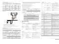
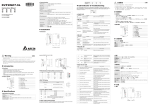
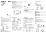
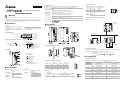
Input and Output Image Tables The mapping of the scanner input and output image (the 1st scanner): Output image D register D6250 – D6281 Explicit message program request D6282 - D6476 DeviceNet output data D6477 – D6497 Length D register Image mapping Length 32 words D6000 – D6031 Explicit message program response 32 words D6032 – D6226 DeviceNet input data 195 words Reserved for other function (do not use these devices in user program) 21 words D6227 – D6247 NS & MS LED DNET scanner identifies the response message by this ID. Therefore, the user has to change the ID value NS LED when completing an explicit message communication for the next transmission. Input image Image mapping ReqID: When sending every explicit message, the user has to assign a Request ID for this explicit message. OFF OFF GREEN No power How to correct Make sure the scanner is powered. Duplicate ID check has not completed Size: The size of message data (starting from D6253); Unit: byte. Service code: The service code of this explicit message. RED MAC ID: The node address of target devices. Reserved for other function (do not use these devices in user program) OFF Indication Command code: Fixed to 01 for every message transmission. Port: Reserved as 0 for every message transmission. 195 words MS LED Words Message Header Using Explicit Message in Application Program DNET scanner can use PLC application program to send the explicit message request and receive explicit Input explicit response Flashing No 24V DC power from RED DeviceNet network D6000 ReqID Status D6001 Port Size D6002 Service code RED RED RED GREEN MAC ID communicating in the network and the baud rate is the same as the setting in DVPDENT. The format of explicit message response: 21 words Make sure at least 1 node or more are Check if the network cable is correctly connected to DVPDNET. Check the 24V DC network power. Hardware error and no Go to your manufacturer or distributor for network power problem-solving. MAC ID detection failure or Change the MAC ID setting and re-power Bus-off DVPDNET. message response. Message Data D6003-D6031 Service response data A Exp Request(PLC->DNET) Status code: D Exp Response (DNET->PLC) DVPDNET RUN STOP DNET Code Status code DVP28SV 28SV Digit-Indicator LED Description 0-63 0 No request transmission 1 Explicit message communication is successful 2 Explicit message communication is in progress 3 Error: Cannot get response from target device 4 Error: Command code is invalid 5 Error: The request data size is invalid 6 Error: The response data size is invalid 7 Error: Cannot connect to target device 8-255 Reserved Indication How to correct Node address of scanner, normal operation None F0 Duplicate MAC ID check failure Change the address and re-power DNET scanner. F1 No scan list is active in the module F2 Low voltage is detected F3 Entering Test Mode F4 Bus-off detected F5 No network power PORT1 PORT2 Slave's explicit response Troubleshooting C F6 Internal error; Flash or Ram check error NS LED F7 Internal error; GPIO check error NS LED status Indication F8 Error in factory manufacturing normal. Switch IN1 from ON to OFF and re-power the scanner. Re-power the scanner. Step A: PLC transfers the explicit message data to DNET scanner. OFF No power or duplicate ID check has not completed Step B: DNET scanner sends the explicit request to target devices. Step C: The target devices process the request and send the response to DNET scanner. Step D: PLC receives the explicit response data. The explicit message is controlled by explicit message program request area and explicit message program response area. The two areas are mapped to D registers in PLC. D register GREEN Normal operation No correction is needed. Flashing RED Error in communication Refer to digit-indicator. D6250 – D6281 Explicit message program request Length D register Image mapping 32 words D6000 – D6031 duplicate ID; Bus-off (please refer to D register 32 words Output explicit request D6250 ReqID Command D6251 Port Size D6252 Service code MAC ID D6253 Class id D6254 Instance id D6256 – D6281 Service data (optional) 1. Make sure all the devices have their unique address. 2. Check the network for correcting media E0 MS LED status Indication Internal error; EEPROM access failure Device key parameter does not match scan list table. OFF No power Flashing GREEN The master is not configured. GREEN Flashing RED RED Make sure the scanner is powered. E2 Salve device in scan list does not exist. E3 Module fails to transmit a message E5 Error detected in sequence of fragmented I/O messages from device. Slave device returns error response when the scanner attempts to communicate with it. Configure the scan list and re-download it to the scanner. E6 Data size returned is bigger than expected. Normal operation No correction is needed. E7 Device is checking MAC ID. Some slaves encounter Refer to digit-indicator and check the scanner communication error. setup. Internal fault in the scanner module (please refer to digit-indicator) If the error still exists after re-power, replace the scanner with a new one. If the error still exists after re-power, replace the scanner with a new one. Make sure that the device parameter in scan list matches the desired key parameter, including vendor ID, product code, device type and version. Data size returned does not match scan list. How to correct scanner with a new one. scanner with a new one. E1 E4 If the error still exists after re-power, replace the If the error still exists after re-power, replace the installation and baud rate. MS LED Explicit message program response response data into D6000 – D6031. The explicit message request format is shown in the table below. Message Data RED check if the network power is normal. Length The user can move the data of explicit request message to D6250 – D6281 and DNET scanner will fill the Message Header Network error; cannot check F9 communicating in the network. No correction is needed, or refer to digit-indicator. Input image Image mapping 2. Make sure at least 1 node or more are No communication digit-indicator) Output image 1. Make sure the scanner is powered. Flashing GREEN Explicit Message Structure Make sure the cable is correctly connected and How to correct DNA02 VFD-B scanner and download it to the scanner. Check if the power of the scanner and PLC MPU is Master's explicit request B No slave device in the scan list. Configure the Re-configure scan list using correct data size. The desired slave device does not exist in the network. Add device to the network. Make sure that the connection is valid and check if the baud rate is correct. Fragmented I/O data is invalid from slave device. None Check slave device configuration and scan list configuration. None Check if the configuration is valid. If the internal error still exists, replace the scanner with a new one. The content of this instruction sheet may be revised without prior notice. Please consult our distributors or download the most updated version at http://www.delta.com.tw/industrialautomation