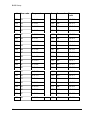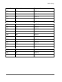
1
BEETLE POS Motherboard With Intel Celeron Processor / Intel Pentium III Processor (D2-CPU-Basic) User Manual POS Motherboard With Intel Celeron Processor / Intel Pentium III Processor (D2-CPU-Basic) User Manual Edition September 2003 All brand and product names mentioned in this document are trademarks of their respective owners. The reproduction, transmission or use of this document or its contents is not permitted without express authority. Offenders will be liable for damages. All rights, including rights created by patent grant or registration of a utility model or design, are reserved. Delivery subject to availability; technical modifications possible. Copyright ©Wincor Nixdorf International GmbH, 2003 Contents Introduction..........................................................................................................1 Overview .............................................................................................................1 Block Diagram .....................................................................................................3 Technical Data ....................................................................................................5 Mechanical Arrangement ....................................................................................9 Onboard Components .......................................................................................11 Processor ..........................................................................................................11 System Memory ................................................................................................11 Graphic System.................................................................................................13 Jumper Settings ................................................................................................14 Audio System ....................................................................................................14 IDE Interface .....................................................................................................15 Floppy Interface.................................................................................................15 Changing the CPU Battery ................................................................................16 Plugin Modules..................................................................................................17 CRT Adapter .....................................................................................................17 PanelLink Adapter .............................................................................................17 LAN 10/100 Adapter..........................................................................................17 PCI Onboard LAN .............................................................................................17 PCI Onboard VGA/4 Controller .........................................................................17 POS Board ........................................................................................................18 Fixed I/O Address Ranges ................................................................................19 Interrupt Assignments .......................................................................................21 DMA Channel Assignments...............................................................................22 PCI-Interface .....................................................................................................23 Devices and Functions ......................................................................................23 Additional onboard Components .......................................................................23 Restrictions........................................................................................................24 Plug and Play ....................................................................................................25 Operating Modes...............................................................................................26 General .............................................................................................................26 Normal Mode/Standby Mode.............................................................................26 Switching on ................................................................................................. 26 Switching Off................................................................................................. 26 Power Failure................................................................................................ 26 Power save Mode..............................................................................................27 Connecting Peripherals .....................................................................................28 Connectors for external Connections ................................................................29 PIN-Assignment COM1*, COM2* ................................................................. 29 CRT .............................................................................................................. 29 CRT .............................................................................................................. 30 TFT Panel Link ............................................................................................. 30 LAN 10/100 .................................................................................................. 31 Microphone................................................................................................... 31 Line Out........................................................................................................ 31 Line In........................................................................................................... 32 CD-Audio...................................................................................................... 32 Speaker Out ................................................................................................. 32 USB1/USB2 (on board) ................................................................................ 32 KYBD............................................................................................................ 33 PS/2 Mouse.................................................................................................. 33 LPT1............................................................................................................. 33 LPT1............................................................................................................. 34 BIOS Setup....................................................................................................... 35 BIOS Menu Bar................................................................................................. 36 Legend Bar ....................................................................................................... 36 General Help..................................................................................................... 37 Scroll Bar .......................................................................................................... 37 Sub-Menu ......................................................................................................... 37 Main screen ...................................................................................................... 38 8086/1130 Rev. ID, 8086/2440 Rev. ID........................................................ 38 System Time [XX:XX:XX] ............................................................................. 38 System Date [XX/XX/XXXX]......................................................................... 38 Legacy Diskette A [Disabled], Legacy Diskette B [Disabled] ....................... 39 Primary & Secondary Master/Slave.............................................................. 39 Installed Memory [XXX MB].......................................................................... 41 Advanced Menu ................................................................................................ 42 Reset Configuration Data [No]...................................................................... 42 Speaker Volume [High]................................................................................. 42 Local Bus IDE adapter [Both] ....................................................................... 42 SMART Device Monitoring [Disabled] .......................................................... 43 PS/2 Mouse [Enabled].................................................................................. 43 Large Disk Access Mode [DOS] ................................................................... 43 Legacy USB Support [Disabled] ................................................................... 43 ISA graphics device installed [No] ................................................................ 43 Boot-Video device [Onboard] ....................................................................... 43 Onboard LAN BootProm [Enabled] .............................................................. 43 QuickBoot Mode [Disabled] .......................................................................... 44 I/O Device Configuration .............................................................................. 44 PCI/PNP ISA UMB Region Exclusion........................................................... 46 PCI/PNP ISA IRQ Region Exclusion ............................................................ 46 DMI Event Logging....................................................................................... 47 Security Menu ................................................................................................... 48 Set Supervisor Password ............................................................................. 48 Processor Serial Number [Disabled] ............................................................ 48 Power Menu...................................................................................................... 48 Power State [Stay off]................................................................................... 49 Power Savings [Disabled] ............................................................................. 49 Resume On Time [Disabled]......................................................................... 49 Wake Up On LAN [Disabled] ........................................................................ 49 HardWare Monitor ........................................................................................ 49 Boot Menu.........................................................................................................50 Exit Menu ..........................................................................................................50 Exit Saving Changes..................................................................................... 51 Exit Discarding Changes............................................................................... 51 Load Setup Defaults ..................................................................................... 51 Discard Changes .......................................................................................... 51 Save Changes .............................................................................................. 51 Test points codes ..............................................................................................52 POS Motherboard: BEEP Codes .................................................................. 61 Abbreviations.....................................................................................................66 Introduction Introduction This manual describes the features of the Central Processing Unit (CPU) for the TM BEETLE systems based on the Intel Celeron Processor family and the Intel TM Pentium III processor. With a frequency of 566 MHz up to 1.2 GHz (Celeron) and of 600 MHz up to 1.26 GHz (Pentium III), second level cache up to 512 KB and many other features, these processors guarantee an increased performance of your BEETLE system. Overview Microprocessor Support for the following processors: R • R Intel Pentium III processor with 100 MHz or 133 MHz host bus speed R TM Intel Celeron processor with 66 MHz or 100 MHz host bus speed • Main Memory Two 168-pin dual in line memory module (DIMM) sockets Supports up to 512MB of PC100 (100MHz) or PC133 (133MHz) Modules Chipset Intel Chipset 815E, consisting of: R • • R Intel FW82815 R Intel 82801 BA PCI-ISA Bridge ITE Bridge IT8888F I/O Controller ITE I/O Cntrl. IT8712F, consisting of: • • • • • • Floppy controller Parallel port 2 Serial Ports Keyboard Interface PS/2 Mouse Interface HW-Monitor 1 Introduction Video system Video Memory part of main memory (max. 10MB under Windows) including 4MB pixel memory CRT resolution up to: • 1600 x 1200 pixel / 8 bit color • 1280 x 1024 pixel / 24 bit color • 1024 x 768 pixel / 24 bit color TFT resolution up to: • 1280 x 1024 pixel / 24 bit color Audio system Chrystal Audio Codec CS4299 Mono Microphone Input Stereo Speaker Output (2 x 1,25W @ 8Ohm) BIOS Firmware Hub: 4 Mbit Flash Memory Phoenix BIOS 4.0 Release 6.0 Peripheral Interfaces • • PS/2 keyboard and mouse shared interface (y-cable optional) Two serial ports One parallel port Two (Four) Universal Serial (USB) ports Two IDE interfaces with Ultra DMA support One FD interface PlugIn Modules • • • • • • • POS Board CRT adapter Sec. Display Controller LAN adapter Panellink TFT adapter VGA/4 PCI controller LAN PCI controller Additional Features • • Wake On LAN technology Wake On Time • • • • 2 Block Diagram Block Diagram The block diagram shows all of the functional units of the D2 Basic - CPU. The physical plug-in connections to the system and external peripherals are shown at the bottom of the diagram. Only the most important internal connectors are part of the block diagram (see next page). 3 4 Panellink Interface 2x22 pol. Serial Interface RS232 Parallel Interface COM1* 9pol. CRT Interface Parallel Interface 2x8 pol. 2x13 pol. Voltage Regulator SMBus System Bus USB 2x4 pol. USB2 1x100pol. PCIInterface PCI Bus PCI Onboard Interface 1x80pol. Graphics & Memory Controller Hub GMCH Memory Bus Synthesizer Loudspeaker 1x4pol. Status Display 1x4pol. SMB 1x4pol. SDRAM 2 Banks 32MB....512MB 2x17 pol. FD Interface Secondary 26pol. Foil Floppy Interface 2x22 pol. Primary 2x22 pol. EIDE Interface I/O Controller Hub ICH2 82801BA Pentium III Processor >=600MHz <=1.26GHz or Celeron Processor >=566MHz <=1.2GHz USB3,USB4 Interface 2x4 pol. USB3,USB4 Interface Firmware Hub FWH 82802 3V Lithium 2x9 pol. Super I/O IT8712F WOLN 1x3pol. ATX 2x10pol. PowerSupply Connector Speaker Mic 2.5mm Stereo 2.5mm Mono Line In 1x3 pol. Stereo Amplifier TEA2025B Audio Codec ‘ 97 CS4299 CD-Audio 1x4pol. FAN 1x3pol. PON 1x4pol. Block Diagram Technical Data Technical Data Supported Systems BEETLE/NetPOS Basic, BEETLE /iPOS Architecture PC-AT compatible Technology TTL,CMOS,LVT; SMD + 5V, +3.3V, AGTL+ technology Operating Modes Normal Mode, Power Save Mode Power Management APM 1.2 Operating Systems WIN 98SE, WIN Me, WIN NT 4.0, WIN2000, LINUX Microprocessor INTEL Celeron (566 MHz – 1.2 GHz) 32 KB L1 Cache, 128/256 KB L2 Cache 370 Pin FC-PGA package R INTEL Pentium III (600 MHz – 1.26 GHz) 32 KB L1 Cache, 256/512 KB L2 Cache 370 Pin FC-PGA package Chipset Intel Chipset 815E, consisting of: TM R • • R Intel FW82815 (GMCH) R Intel 82801 BA (ICH2) Max. Resolution CRT 1600 x 1200 pixel/ 8 color bit 1280 x 1024 pixel/ 24 color bit 1024 x 768 pixel/ 24 color bit Max. Resolution TFT 1280 x 1024 pixel/ 24 color bit Super I/O IT8712F with the following functions: Floppy Cntrl., Parallel Port, 2 Serial Ports, Keybd. Interface, PS/2 Mouse Interface, HW- Monitor 5 Technical Data Sound Controller CS4299 Audio Codec controller with the following AC‘ 97 functions: 20 Bit Stereo DAC and 18 Bit Stereo ADC Analog Line-Level Input (CD) Mono Mic Input (MIC) Stereo Line-Level Output Sound Connection Mono Microphone Input, Stereo Speaker Output (2 x 1,25 W@ 8 Ohm) Main Memory 2 DIMM - sockets (168 pin), 3.3 V SDRAM technology, unbuffered, PC100/PC133 - Standard DIMM Height up to 35 mm 32MB to 512MB, Combinations of different modules are possible PCI Interface PCI-Bus (32 bit interface, 33MHz) BIOS >=4 MBit Flash Memory, Phoenix BIOS, PnP ISA/PCI Rev.1.0A DMI-Support Battery 3 V Lithium for RTC and NVRAM Type: CR1/3 N , 160 mAh SDRAM Bus Frequency 100 MHz, 133MHz System BUS Frequency 66 MHz, 100 MHz, 133 MHz PCI Bus Frequency 33 MHz Wake On feature Wake On LAN, Wake On Time Keyboard Connection PC-AT compatible PS/2-Mouse Connection via Y-cable together with keyboard Serial Interfaces COM1*, COM2* Parallel Interface IEEE1284 compatible (ECP, EPP, PS/2 compatible) 6 Technical Data Loudspeaker AT-compatible, Volume Control defined by BIOS Setup in 3 steps: high-, medium-, low volume Floppy disk Connection Standard interface CMOS, NEC 765 compatible, foil connector and 2.54 mm connector Hard disk Connection Local Bus IDE interface, Primary/Secondary for 4 drives, PIO Mode 0 - Mode 4, ULTRA DMA Mode 0 – Mode 2, 2mm connector for primary and secondary each USB Connection Version 1.1 USB1, 2: Standard 2 port connector, series A USB3,4: 2 x 4 pin connector for separate adapter PCI Plug-in card Interface 32 bit interface, 33 MHz Status display Connection Support for LEDs: Power On and HD activity Current Consumption Celeron/566MHz 256MB RAM, POS Board 3.2 A @ +5V 2.0 A @ +3.3V 0,5 A @ +5V Standby 60 mA @ +12V 50 mA @ -12V Current Consumption Celeron/51.2 GHz 256MB RAM, POS Board 4.6 A @ +5V 2.1 A @ +3.3V 0,5 A @ +5V Standby 60 mA @ +12V 50 mA @ -12V Current Consumption Pentium III/1.26 GHz 256MB RAM, POS Board 4.3 A @ +5V 2.2 A @ +3.3V 0,5 A @ +5V Standby 60 mA @ +12V 50 mA @ -12V 7 Technical Data Max. Current for keyboard +5V: 500 mA Max. Current per port (for COM1*,2*) +12V: 600 mA Max. Current in total (for COM1*,2*) +12V: 900 mA Max. Current per port (for COM1*,2*) +5V: 300 mA Max. Current in total (for COM1*,2*) +5V: 500 mA Max. Current per port Standard USB1,USB2, USB3, USB4 +5V: 500 mA Fuses (Polyswitches) 8 +5V COM1*, COM2*, USB1, USB2, Keyboard, Mouse USB3, USB4 – polyswitches on separate adapter +12V COM1*, COM2* Board Dimensions 192 mm x 209 mm Mechanical Arrangement Mechanical Arrangement The CPU comprises the printed circuit board with connectors for all external peripheral connections and for installing the optional plug-in cards. PCI-INTERFACE 1 LPT PT PCI-ONBOARD ICH2 Quarz AC97 COM1* PWON USB1/ USB2 ATXPOWER FD/F FD MS/INT KYB/ MSE SuperI/O SuperI/O IT8712F IT8712F BIOS FWH IDE2 MIC USB3,4 VGA/CRT CS4299 COM2* IDE1 CELERON LINE IN CD-AUDIO PENTIUM III VGA/TFT DIMM0 DIMM1 L12V L5V SPK OUT or LED SP LAN GMCH 9 Mechanical Arrangement In the following configuration examples the POS –Board is assembled and contains the logic for COM3, COM4, COM5, COM6 and the cashdrawer. COM5: Internally used; COM6: Not used iPOS Configuration /w internal PLINK TFT connection, LPT1 and LAN adapter COM4 LPT COM1* COM2* COM3 LAN MIC Cashdrw. Keyb/Mouse USB SPK iPOS Configuration /w internal PLINK TFT connection, LPT1, LAN adapter and secondary Display (CRT) connection CRT Display LPT COM1* COM2* COM3 LAN MIC Cashdrw. Keyb/Mouse USB SPK iPOS Configuration /w internal PLINK TFT connection, LPT1, LAN adapter and secondary Display (CRT) connection CRT Display COM 4 COM1* MIC Cashdrw. Keyb/Mouse USB 10 COM2* COM3 LAN SPK Onboard Components Onboard Components Processor The D2- CPU Basic supports Pentium III processors as well as Celeron processors in FC-PGA package. The released types are: Processor type Celeron Celeron Pentium III Pentium III Pentium III Processor speed 566 MHz 1.2 GHz 600 MHz 866 1.26 Host Bus frequency 66MHz 100 100 MHz 133 133 Cache size 128 KB 256 256 KB 256 512 Memory Bus frequency 100 MHz 100 MHz 100 MHz 133 MHz 133 MHz The frequency selection is automatically selected . Also the core voltage – which depends on processor type and revision version – are defined automatically by the processors VID pins. Attention: The passive heatsink has to be installed correctly. The heatsink paste is absolutely necessary. The processor fan – if installed – has to be controlled whether it works properly, thus avoiding malfunctions of the CPU!. System Memory On the D2-CPU Basic two DIMM sockets are provided for connecting memory modules in SDRAM technology up to 512 MByte ( 2x 256 MB). DIMMs with different sizes can be used. One or both DIMM modules can be assembled. The DIMMs are unbuffered 3.3V memory modules. 11 Onboard Components Main Memory Socket 1 Socket 2 Total capacity 8MBx64 (8MBx64) 64 MB(128 MB) 16MBx64 (16MBx64) 128 MB(256 MB) 32MBx64 (32MBx64) 256 MB(512 MB) Î Any combinations of these three DIMMs are allowed. The following table shows possible combinations of processors, PC100 modules and PC133 modules. Celeron 566 MHz Celeron 1.2 GHz PentiumIII 600 MHz PentiumIII 866 MHz PentiumIII 1.26 GHz PC100 Module s FSB 66MHz SDRAM 100MHz FSB 100MHz SDRAM 100MHz FSB 100MHz SDRAM 100MHz FSB 133MHz SDRAM 100MHz FSB 133MHz SDRAM 100MHz PC133 Module s FSB 66MHz SDRAM 100MHz FSB 100MHz SDRAM 100MHz FSB 100MHz SDRAM 100MHz FSB 133MHz SDRAM 133MHz FSB 133MHz SDRAM 133MHz FSB: Front Side Bus (Processor frequency) SDRAM: Ram Frequency 12 Onboard Components Graphic System The main part of the graphic system is the Graphic Memory Controller Hub (GMCH) – part of the chipset. It contains the complete graphic system as well as the memory controller. The Video memory is part of the main memory (max. 10 MB under Windows) including 4MB pixel memory. The Graphic Controller supports 2D and 3D graphics. The maximum resolution depends on the connected monitor type: Max. Resolution CRT: 1600 x 1200 pixel / 8 colors bit 1280 x 1024 pixel / 24 color bit 1024 x 768 pixel / 24 color bit Max. Resolution TFT: 1280 x 1024 pixel / 24 color bit Because the different Flatpanels from Wincor Nixdorf are optimized for a special resolution, every Flatpanel has its own jumper setting. The following jumpersetting is defined; unused combinations are reserved for the future. 13 Onboard Components Jumper Settings VIDEO Mode DISPLAY Size Display Type / Clock Freq. closed closed closed SVGA TFT 12" BA 72A (30 MHz) closed closed open XGA TFT 15" BA 73A (65 MHz) closed open SVGA TFT 12" BA 72A–1 (38 MHz) TFT 10" 640 x 480 PT 3 open PT 2 PT 1 open closed closed VGA 1 12” Monitor BA72A PT: used in BEETLE/ iPOS 1 15” Monitor BA73A PT: used in BEETLE/ iPOS 1 12” Monitor BA72A-1 PT: 1 10” Monitor 640 x 480 PT: Audio System The audio systems contains on the AC`97 compatible Sound controller – part of the chipset - , the CODEC ( CS4299 from Chrystal) and the audio amplifier . The stereo output is 1.25W at 8 Ohm for each channel. 14 Onboard Components IDE Interface For connecting IDE drives there are 2 connectors on the CPU available. The connectors are 2mm header, 44 pin with +5V power supply. 2.5” hard disc drives and CDROM/DVD drives are connected without additional power lines. 3.5” drives are connected via an adapter cable, which differs between the various BEETLE models. The interface may be driven in PIO mode 0 – mode 4 or in UDMA mode 0 – 2. Floppy Interface For connecting Floppy drives there are two different connectors on the CPU available. These are a 2.54mm standard header for 1” drives and a foil cable connector for ½” drives. Standard 1.44MB and 720KB Floppy Discs are supported. 15 Changing the CPU Battery Changing the CPU Battery The BEETLE POS systems are equipped with a lithium battery on the CPU board to ensure data retention, the time and the setup parameters. The battery should be changed approximately every five years. Î When inserting the new battery, make sure the polarity is correct. This is visibly marked in the socket. Incorrect replacement of the battery may lead to the danger of explosion. The battery is located in a socket in the CPU (see page 9). To gain access to the battery, proceed as described in the according chapters of your BEETLE User Manual. The lithium battery must be replaced only by identical batteries or types recommended by Wincor Nixdorf. You can return the used batteries to your Wincor Nixdorf sales outlet. Batteries containing harmful substances are marked accordingly. The chemical denotations are as follows: CD = Cadmium; Pb = Lead, Li = Lithium. This symbol on a battery tells you that batteries containing harmful substances must not be disposed of as household waste. Follow the country specific laws and regulations. Within the European Union you are legally bound to return these batteries to the service organisation where you purchased the new battery. Î The setup parameters must be reset each time the battery is changed. 16 Plugin Modules Plugin Modules CRT Adapter If a CRT adapter is installed, you can connect any VGA monitor (e.g. the MO34) to the BEETLE system via the 15-pin D-sub jack on the CRT adapter. Power is supplied to the monitor via the rubber connector on the BEETLE, located on the back of the housing. PanelLink Adapter The PanelLink adapter serves as interface for connecting BA72A, BA72A-1 or BA73A to the D2- CPU Basic. The TFT adapter (C2-CPU) and the PanelLink adapter (D1-CPU) must not be used on the D2- CPU Basic. LAN 10/100 Adapter While the LAN controller is part of the INTEL chipset the LAN adapter contains the physical layer including Ethernet address. The LAN adapter was developed for the D2- CPU and may be used on D2-CPU Basic as well. PCI Submodule LAN A PCI Onboard LAN controller (3Com; Realtek) may be used alternatively to the LAN adapter. PCI Submodule VGA/4 Controller The PCI Onboard VGA/4 controller may be assembled alternatively to any other PCI Onboard controller. It supports 2 monochrome displays, e.g. BA69 (5.7”) and BA70 (10.4”). 17 Plugin Modules POS Board The POS Board contains the logic for optional four further serial interfaces COM3 to COM6. While COM3 and COM4 are available on 9pin DSUB connectors, COM5 is used for internal Touch function. COM6 is not used (see also page 10). The cash drawer logic is also a part of the POS Board. 18 Fixed I/O Address Ranges Fixed I/O Address Ranges The following table contains all of the I/O address lines of the CPU. The access type and the bit width are specified alongside the port address and the function performed by the command. PORT ADDRESS FUNCTION 0000h-001Fh 0020h-002Dh DMA controller Interrupt controller 002Eh-002Fh 0030h-003Dh 0040h-0043h 004Eh-004Fh 0050h-0053h 0060h-0066h, even 0061h-0067h, odd 0070h-0076h, even 0071h-0077h 0080h-0091h 0092h 0093h-009Fh LPC SIO Interrupt controller Timer/Counter LPC SIO Timer/Counter LPC NMI NMI/RTC RTC DMA controller Reset DMA controller 00A0h-00B1h 00B2h-00B3h 00B4h-00BDh 00C0h-00DFh 00F0h 0170h-0177h 01F0h-01F7h 0230h-0270h Interrupt controller Power Management Interrupt controller DMA controller FERR#/IGNNE#/Interrupt controller Hard disk, primary Hard disk, secondary Serial interface COM4 (w/ POS board Type2) Serial interface COM4 (w/ POS board Type1) Hardware Monitor Serial interface COM5 (w/ POS board) 0270h-0277h 0290h-029Fh 2E0h-2E8h 19 Fixed I/O Address Ranges PORT ADDRESS 20 02F8h-02FFh 0300h-030Fh FUNCTION Serial interface COM2* Reserved for testing 0310h-031Fh 0328h-032Fh 0376h 03C0h-03CFh 03D4h-03D5h 03DAh 03E8h-03EFh 03F0h-03F7h 03F6h 03F8h-03FFh 04D0h-04D1h 0CF9h POSboard Serial interface COM6 (w/ POS board) Hard disk, primary Graphic system Graphic system Graphic system Serial interface COM3 (w/ POS board) FDC primary Hard disk, secondary Serial interface COM1* Interrupt controller Reset F80h-FFFh 1000h-1FFFh GPIO addressing 815E chipset addressing Interrupt Assignments Interrupt Assignments The interrupt assignments correspond to the standard AT assignments plus POS- specific characteristics. Interrupt no. IRQ0 IRQ1 IRQ2 IRQ3 IRQ4 IRQ5 IRQ6 IRQ7 IRQ8 IRQ9 IRQ10 IRQ11 IRQ12 IRQ13 IRQ14 IRQ15 Cause of interrupt Timer output 0 Keyboard Cascade COM2* COM1* LAN / available Floppy disk LPT/available Realtime clock Power failure / available available available PS/2Mouse/available (Coprocessor) HD(Primary HD(Secondary)/available “Available” means the availability of PCI and/or PnP components. Î One Interrupt of IRQ9, IRQ10 and IRQ11 will be used by the BIOS system manager. 21 DMA Channel Assignments DMA Channel Assignments The DMA channel assignments correspond to the assignments in the AT standard. DMA channel DMA0 DMA1 DMA2 DMA3 DMA4 DMA5 DMA6 DMA7 Assignment spare spare Floppy disk spare Cascade for Ctlr 1 spare spare spare DMA1 or DMA3 will be used by LPT in EPP mode. 22 PCI-Interface PCI-Interface Devices and Functions The ICH2 incorporates a variety of PCI functions as shown in the table below. These functions are divided into three logical devices: (Bus0, Device30 ; Bus0, Device31 and Bus1, Device8). BUS: DEVICE:FUNCTION FUNCTION DESCRIPTION Bus 0: Device 30: Function 0 Hub Interface to PCI Bridge Bus 0: Device 31: Function 0 PCI to LPC Bridge Bus 0: Device 31: Function 1 IDE Controller Bus 0: Device 31: Function 2 USB Controller #1 Bus 0: Device 31: Function 3 SMBus Controller Bus 0: Device 31: Function 4 USB Controller #2 Bus 0: Device 31: Function 5 AC´97 Audio Controller Bus 0: Device 31: Function 6 AC´97 Modem Controller Bus 1: Device 8: Function 0 LAN Controller Additional onboard Components There are two Onboard PCI connectors assembled on the D2 BASIC- CPU. A complete PCI–Bus is implemented on the Onboard PCI connector for assembling a POSboard. The second Onboard PCI connector may be used to assemble alternatively one Plug In Module with up to two PCI-Slot functionalities (double sided). 23 PCI-Interface Available are the LAN modules (3COM and Realtek); an Onboard VGA/4Submodule and a second CRT controller. Bus 1: Device 10: Function 0 Bus 1: Device 12: Function 0 Onboard LAN- Submodule Onboard VGA/4- Submodule Restrictions The implementation of PCI is based on the specification 2.0. No support of PCI cacheable memory (SBO# and SDONE signals are not on the interface connector). No support of 64 bit bus extension. No support of JTAG/Boundary Scan pins. 24 Plug and Play (PnP) Plug and Play (PnP) The BIOS supports PnP capabilities by managing the system resources. All I/Oaddresses, IRQ-channels and DMA channels, which are used by the system are marked as reserved and the remaining resources are available for the PnP – OS. See also BIOS specification (page 35ff). Î COM3, COM4, COM5, COM6 are no PnP devices. They have to be set manually in the BIOS setup (see also table on page 19ff). 25 Operating Modes Operating Modes General The D2 BASIC- CPU provides power management functions dependent on the installed Operating System (OS). Normal Mode/Standby Mode Switching on Normal Flex ATX Power Supply will be used in D2 BASIC- CPU based systems. Connecting the PSU via AC line the Standby voltage P5VSB is supplied and the system is ready to be switched on (Standby mode). There are several possibilities to switch on the system. The “regular” way to switch on the system is to activate the temporary switch at the frontside of the system. Î Short pressing the temporary switch will switch on the system. For powering up the system via LAN the Onboard PCI connector is provided with the “Wake up” signal and the Standby voltage P5VSB. Last not least the RTC can be used to switch on the system. Switching Off The system may be switched off either by activating the temporary switch at the frontside of the system or under Software Control. Î Pressing the temporary switch longer than 4 seconds will switch off the system. Power Failure If the main power fails (AC input) for longer than 20 msec, the loss of Standby Voltage results in powering down the system. After the main power returns the system responds depending on the BIOS Setup setting. If in the BIOS Setup “Restore” is chosen, the system enters the state before Power failure. If in the BIOS Setup “Stay Off” is chosen, the system stays off. 26 Operating Modes Power save Mode The Power Save Mode supports the following items: Processor enters the “Toggle Mode” Harddiscs are switched off after defined time Monitor is switched off after defined time 27 Connecting Peripherals Connecting Peripherals Î When connecting peripherals always make sure that the system is switched off! The motherboard offers a total of four serial interfaces: COM1 - COM4* and interfaces for connecting displays, modular printers, keyboards, USB-devices, loudspeaker and for the network connection. 28 Connecting Peripherals Connectors for external Connections PIN-Assignment COM1*, COM2* COM1* and COM2* are BEETLE standard RS232 interfaces with +5V and +12V power lines on a 9 pin D-SUB connector, type female. PIN # 1 2 3 4 5 6 7 8 9 COM1* P12VFS RXD1 TXD1 DTR1 GNDF DSR1 RTS1 CTS1 P5VFS COM2* P12VFS RXD2 TXD2 DTR2 GNDF DSR2 RTS2 CTS2 P5VFS CRT You have the choice of using several adapters for connecting different types of displays. CRT Adapter If a CRT adapter is installed, you can connect any VGA monitor (like the MO34) to the BEETLE system via the 15-pin D-sub jack on the CRT adapter. Power is supplied to the monitor via the rubber connector on the BEETLE, located on the back of the housing. The CRT interface connector is a standard 15 pin HDD-SUB connector, type female. PIN # 1 2 3 4 5 6 7 8 SIGNALS VID RED GREEN BLUE NC GND GND GND GND 29 Connecting Peripherals CRT PIN # 9 10 11 12 13 14 15 SIGNALS VID 5VFU GND NC DDCSDA FHSYNC FVSYNC DDCSCL TFT Panel Link With a TFT Panel Link adapter you can also connect the displays BA72A (12”) or BA73A (15”) via the 40 pin ITDR-connector. If one of these displays is connected, the internal loudspeaker of the system must be disconnected! The panellink interface connector is a 40 pin Mini Delta Ribbon connector, type female. PIN # 1 3 5 7 9 11 13 15 17 19 21 23 25 27 29 31 33 35 37 39 30 SIGNALS TFT GND TX2 Shield P12V TX1+ TX1P12V P12V Touch Shield FPEN TX0 Shield P5V TXC+ TXCNC NC NC NC NC NC NC PIN # 2 4 6 8 10 12 14 16 18 20 22 24 26 28 30 32 34 36 38 40 SIGNALS TFT TX2+ TX2GND TX1 Shield GND P12V Shield TXD RXD TX0+ TX0P5V TXC Shield Speaker Out NC NC NC NC NC NC NC Connecting Peripherals LAN 10/100 If a network adapter or controller board is installed, the system can be connected to a network (LAN 10/100 Mbit) from the POS terminal back panel. If a LAN adapter or controller board is not installed, this location on the back panel is closed by a dummy cover. The connector for the LAN10/100 interface is a 8 pin RJ45 connector, type female. PIN # 1 2 3 4 5 6 7 8 SIGNALS TD + TD RD + NC NC RD NC NC Microphone The Microphone connector is a 5 pin 3.5 mm female connector. PIN # 1 2 3 4 5 SIGNALS MIC AGND MICF NC MICF VREFOUT Line Out The Line Out connector is a 5 pin 3.5 mm female connector . PIN # 1 2 3 4 5 SIGNALS OUT AGND LOR NC LOL NC 31 Connecting Peripherals Line In The Line In connector is a 3 pin header. PIN # 1 2 3 SIGNALS CD LIL LIR AGND CD-Audio The CD-Audio connector is a 4 pin header. PIN # 1 2 3 4 SIGNALS CD AGND CDIL AGND CDIR Speaker Out The connector for the speaker is a 5 pin 3.5 mm connector, type female. PIN # 1 2 3 4 5 SIGNALS Out AGND LOLAF NC LORAF NC USB1/USB2 (on board) The USB interface contains 2 downstream ports providing the data rates of 12 MHz for high speed USB peripherals and 1.5 MHz for low speed USB peripherals. Only devices equipped with a shielded cable must be connected to the USB interface. USB1, USB2 are standard USB ports, connector series A, male PIN # 1 2 3 4 32 USB1 P5VFUS1F U1DU1D+ GNDF1 USB2 P5VFUS2F U2DU2D+ GNDF2 Connecting Peripherals KYBD Your BEETLE system has a 6-pin mini-DIN jack for connecting a keyboard. Make sure that the connector is plugged firmly into the socket to prevent malfunctioning. Power is supplied to the keyboard via this socket. If you wish to connect a standard PC keyboard with DIN connector, you must use a special adapter cable, obtainable from the Wincor Nixdorf International branch office responsible for your area. BEETLE keyboards with PS/2 interface may be connected. PIN # 1 2 3 4 5 6 KYB/E KD MSD GND P5VF KC MSC PS/2 Mouse You may connect a PS/2 Mouse via an y-cable to the keyboard connector. The cable is obtainable from the Wincor Nixdorf International branch office reponsible for your area. PIN # 1 2 3 4 Signals PS/2 GNDFKYHL MSCKF MSDAF P5VFKYHL LPT1 The standard parallel interface LPT1 is intended for connecting a modular printer. You will find more information on how to connect other POS printers and more POS peripherals (e.g. Cash Drawers) to your BEETLE system in the User Manuals that come along with your BEETLE system. Î This LPT1 connector is not a part of the D2 Basic CPU. It is a part of the LPT adapter cable and available at the rearside of the cabinet. The LPT1 port is provided with a standard 25 pin D-Sub connector (LPT), female. 33 Connecting Peripherals LPT1 PIN # 1 2 3 4 5 6 7 8 9 10 11 12 13 34 LPT STRBEN CEN D0 CEN D1 CEN D2 CEN D3 CEN D4 CEN D5 CEN D6 CEN D7 ACKN PBUSY PE SLCT PIN # 14 15 16 17 18 19 20 21 22 23 24 25 LPT AUTOFN ERRORN INITN SLCTIN GND GND GND GND GND GND GND GND BIOS Setup BIOS Setup The Celeron / Pentium III mainboard comes with a Phoenix BIOS chip that contains the ROM Setup information of your system. This chip serves as an interface between the processor and the rest of the mainboard’s components. This section explains the information contained in the Setup program and tells you how to modify the settings according to your system configuration. Even if you are not prompted to use the Setup program, you might want to change the configuration of your system in the future. For example, you may want to enable the Security Password Feature or make changes to the power management settings. It will then be necessary to reconfigure your system using the BIOS Setup program so that the system can recognize these changes and record them in the CMOS RAM or the FLASH ROM. The BIOS ROM of the system holds the Setup utility. When you turn on the system, it will provide you with the opportunity to run this program. This appears during the Power-On Self Test (POST). Press <F2> to call the Setup utility. If you are a little bit late pressing the mentioned key, POST will continue with its test routines, thus preventing you from calling Setup. If you still need to call Setup, reset the system by pressing <Ctrl> + <Alt> + <Delete>. You can also restart by turning the system off and then on again. But do so only if the first method fails. The Setup program has been designed to make it to use as easy as possible. It is a menu-driven program, which means you can scroll through the various submenus and make your selections among the predetermined choices. When you invoke Setup, the main program screen will appear. On the following pages you will read more information about the Setup entries. Î NOTE: Because the BIOS software is constantly being updated, the following BIOS screens and descriptions are for reference purposes only and may not reflect your BIOS screens exactly. 35 BIOS Setup BIOS Menu Bar The top of the screen has a menu bar with the following sections: MAIN ADVANCED SECURITY POWER BOOT EXIT Use this menu to make changes to the basic system configuration. Use this menu to enable and make changes to the advanced features. Use this menu to enable a supervisor password. Use this menu to configure and enable Power Management features. Use this menu to configure the default system device used to locate and load the Operating System. Use this menu to exit the current menu or specify how to exit the Setup program. To access the menu bar items, press the right or left arrow key on the keyboard until the desired item is highlighted. Legend Bar At the bottom of the Setup screen you will notice a legend bar. The keys in the legend bar allow you to navigate through the various setup menus. The following table lists the keys found in the legend bar with their corresponding alternates and functions. Navigation Key(s) <F1> <Esc> ← or → (keypad arrows) ↑ or ↓ (keypad arrows) - (minus key) + (plus key) or spacebar 36 Function (Description) Displays the General Help screen from anywhere in the BIOS Setup. Jumps to the Exit menu or returns to the main menu from a submenu. Select the menu item to the left or right. Moves the highlight up or down between fields. Scrolls backward through the values for the highlighted field. Scrolls forward through the values for the highlighted field. BIOS Setup Navigation Key(s) <Enter> <Home> or <PgUp> <End> or <PgDn> <F9> <F10> Function (Description) Brings up a selection menu for the highlighted field. Moves the cursor to the first field. Moves the cursor to the last field. Loads the default configuration into Setup. Saves changes and exits Setup. General Help In addition to the Item Specific Help window, the BIOS setup program also provides a General Help screen. This screen can be called from any menu by simply pressing <F1> or the <Alt> + <H> combination. The General Help screen lists the legend keys with their corresponding alternates and functions. Scroll Bar When a scroll bar appears to the right of a help window, it indicates that there is more information to be displayed that will not fit in the window. Use <PgUp> and <PgDn> or the up and down keys to scroll through the entire help document. Press <Home> to display the first page, press <End> to go to the last page. To exit the help window, press <Enter> or <Esc>. Sub-Menu Note that a right pointer symbol appears to the left of certain fields. This pointer indicates that a sub-menu can be launched from this field. A sub-menu contains additional options for a field parameter. To call a sub-menu, simply move the highlight to the field and press <Enter>. The sub-menu then will appear immediately. Use the legend keys to enter values and move from field to field within a sub-menu just as you would do within a menu. Use the <Esc> key to return to the main menu. Take some time to familiarize yourself with each of the legend keys and their corresponding functions. Practice navigating through the various menus and sub-menus. If you accidentally make unwanted changes to any of the fields, use the set default hot key <F9>. While moving around through the Setup program, note that explanations appear in the Item Specific Help window located to the right of each menu. This window displays the help text for the currently highlighted field. 37 BIOS Setup Main screen When the Setup program is accessed, the following screen appears: ¾ ¾ ¾ ¾ 8086/1130 Rev. ID: 8086/2440 Rev. ID: 04 05 System Time: System Date: [08:14:46] [12/20/1999] Legacy Diskette A: Legacy Diskette B: [1.44 MB 31/2“] [Disabled] Primary Master Primary Slave Secondary Master Secondary Slave [1090MB] [None] [None] [None] Extended Memory: 125 MB 8086/1130 Rev. ID, 8086/2440 Rev. ID This field displays the revision of the i815E chipset. This is a display only field. System Time [XX:XX:XX] Sets your system to the time that you specify (usually the current time). The format is hour, minute, second. Valid values for hour, minute, and second are: Hour: (00 to 23), Minute: (00 to 59), Second: (00 to 59). Use the <Tab> or <Shift> + <Tab> keys to move between the hour, minute, and second fields. System Date [XX/XX/XXXX] Sets your system to the date that you specify (usually the current date). The format is month, day, year. Valid values for month, day, and year are: Month: (1 to 12), Day (1 to 31), Year: (up to 2079). Use the <Tab> or <Shift> + <Tab> keys to move between the month, day, and year fields. 38 BIOS Setup Legacy Diskette A [Disabled], Legacy Diskette B [Disabled] These fields record the types of floppy disk drives installed in your system. Configuration options: [Disabled] [720K, 3.5 in.] [1.44M, 3.5in.] Primary & Secondary Master/Slave Î Note: Before attempting to configure a hard disk drive, make sure you have the configuration information supplied by the manufacturer of the drive. Incorrect settings my cause your system to not recognize the installed hard disk. To allow the BIOS to detect the drive type automatically, select [Auto]. Type: [Auto] CHS Format Cylinders: Heads: Sectors: Maximum Capacity [ 2112] [16] [63] 1090MB LBA Format Total Sectors Maximum Capacity 2128896 1090MB Multi-Sector Transfers: LBA Mode Control: 32 Bit I/O: Transfer Mode: Ultra DMA Mode SMART Monitoring: [8 Sectors] [Enabled] [Disabled] [Fast PIO 4] [Disabled] Disabled Type [Auto] Select [Auto] to automatically detect an IDE hard disk drive. If automatic detection is successful, the correct values will be filled in for the remaining fields on this sub-menu. If automatic detection fails, your hard disk drive may be too old or too new. You can try updating your BIOS or enter the IDE hard disk drive parameters manually. Î Note: After the IDE hard disk drive information has been entered into BIOS, new IDE hard disk drives must be partitioned (such as with FDISK) and then formatted before data can be read from and write on. Primary IDE hard disk drives must have its partition set to active(also possible with FDISK). 39 BIOS Setup Other options for the Type field are: [None] to disable IDE devices. Î IMPORTANT: If your hard disk was already formatted on an older previous system, incorrect parameters may be detected. You will need to enter the correct parameters manually or use low-level format if you do not need the data stored on the hard disk. If the parameters listed differ from the ones used when the disk was formatted, the disk will not be readable. If the auto detected parameters do not match the ones that should be used for your disk you should enter the correct ones manually by setting [User]. [User] Manually enter the number of cylinders, heads and sectors per track for your drive. Refer to your drive documentation or look on the drive for this information. If no drive is installed or if you are removing a drive and not replacing it, select [None]. Cylinders This field configures the number of cylinders. Refer to your drive documentation to determine the correct value to enter into this field. Î Note: To make changes to this field, the Type field must be set to [User]. Heads This field configures the number of read/write heads. Refer to your drive documentation to determine the correct value to enter into this field. Î Note: To make changes to this field, the Type field must be set to [User]. Sector This field configures the number of sectors per track. Refer to your drive documentation to determine the correct value to enter into this field. Î Note: To make changes to this field, the Type field must be set to [User]. Maximum Capacity This field shows the drive’s maximum capacity calculated automatically by the BIOS from the drive information you entered. Multi-Sector Transfers [Maximum] This option automatically sets the number of sectors per block to the highest number supported by the drive. This field can also be configured manually. Note 40 BIOS Setup that when this field is configured automatically, the value set may not always be the fastest value for the drive. Refer to the documentation that came with your hard drive to determine the optimal value and set it manually. Î Note: To make changes to this field, the Type field must be set to [User]. Configuration options: [Disabled] [2 Sectors] [4 Sectors] [8 Sectors] [16 Sectors]. LBA Mode Control [Enabled] Select the hard disk drive type in this field. When Logical Block Addressing is enabled, 28-bit addressing of the hard drive is used without regard for cylinders, heads, or sectors. Note that Logical Block Access may decrease the access speed of the hard disk. However, LBA Mode is necessary for drives with greater than 504MB in storage capacity. Configuration options: [Enabled] [Disabled]. 32 Bit I/O [Disabled] This field setting enables or disables the 32 Bit IDE data transfers. Configuration options: [Disabled] [Enabled]. PIO Mode This option lets you set a PIO (Programmed Input/Output) mode for the IDE device. Modes 0 through 4 provide successively increased performance. Configuration options: [Standard] [Fast PIO 1] [Fast PIO 2] [Fast PIO 3] [Fast PIO 4] [FPIO 3 / DMA 1] [FPIO 4 / DMA 2]. Other options for Type are: [CD-ROM] – for IDE CD-ROM drives After using the legend keys to make your selections on this sub-menu, press the <Esc> key to exit back to the Main menu. When the Main menu appears, you will notice that the drive size appear in the field for the hard disk drive that you just configured. SMART Monitoring This field informs about the enabling of the S.M.A.R.T. (Slef-Monitoring, Analysis and Reporting Technology) system which utilizes internal hard disk drive monitoring technology. This field is read only. Installed Memory [XXX MB] This field displays the amount of extended memory detected by the system during bootup. You do not need to make changes to this field. This is a display only field. 41 BIOS Setup Advanced Menu Reset Configuration Data: Speaker Volume: Local Bus IDE adapter: SMART Device Monitoring: PS/2 Mouse: Large Disk Access Mode: Legacy USB Support ISA graphics device Boot-Video device Onboard LAN BootProm: QuickBoot Mode: ¾ ¾ ¾ ¾ [No] [High] [Both] [Disabled] [Enabled] [DOS] [Disabled] [No] [Onboard] [Enabled] [Disabled] I/O Device Configuration PCI/PNP ISA UMB Region Exclusion PCI/PNP ISA IRQ Resource Exclusion DMI Event Logging Reset Configuration Data [No] [Yes] erases all configuration data in a section of memory for ESCD (Extended System Configuration Data) which stores the configuration settings for non-PnP Plug-in devices. Configuration options: [No] [Yes] Î If you are facing problems after adding or removing any hardware components to the system it might be wise to select the [Yes] option once. This allows the BIOS to reconfigure available hardware resources. Speaker Volume [High] This field is for the volume control of the installed speaker. Configuration Options: [High] [Middle] [Low]. Local Bus IDE adapter [Both] You can select to enable the primary IDE channel, secondary IDE channel, both, or disable both channels. Configuration options: [Both] [Primary] [Secondary] [Disabled]. 42 BIOS Setup SMART Device Monitoring [Disabled] This field controlls the enabling of the S.M.A.R.T. (Self-Monitoring, Analysis and Reporting Technology) system which utilizes internal hard disk drive monitoring technology. Configuration options: [Disabled] [Enabled]. PS/2 Mouse [Enabled] With the default setting [Disabled] IRQ12 will be available for installed expansion cards. [Enabled] will always reserve IRQ12, regardless whether a PS/2 mouse is detected or not. Configuration options: [Disabled] [Enabled] Large Disk Access Mode [DOS] For UNIX, Novell Netware, or other operating systems you have to select [Other]. For DOS or Windows use the value of default [DOS]. Configuration options: [DOS] [Other]. Legacy USB Support [Disabled] This motherboard supports Universal Serial Bus (USB) devices. Selecting the default of [Disabled], the USB controller is disabled no matter whether you are using a USB device or not. The enabling of the controller will run with the help of a USB compliant operating system like Windows 98 or else. If the point stands on [Enabled] the legacy USB support from the BIOS is started. Now it is possible to use a USB keyboard to start this setup or with the standard DOS environment. If you like to use a USB-Floppy disk or a USB CD-ROM device for booting, you have to enable this setup point and after detecting of this USB device from the BIOS, you have to switch the Boot order to the appropriate device. Configuration Options: [Disabled] [Enabled] ISA graphics device installed [No] Some nonstandard VGA cards may not show colors properly. The settings [Yes] should correct this problem. Otherwise, leave this on the default setting of [No]. Configuration options: [No] [Yes]. Boot-Video device [Onboard] The mainboard has an Onboard graphic adapter. If your computer has additionally installed a PCI VGA card, this field allows you to select which of the cards will act as your primary display card. The default, [Onboard], allows your PCI card to take precedents only when no onboard bridge is detected. [PCI-Slot] uses the PCI VGA adapter card as primary card. Configuration options: [Onboard] [PCI-Slot]. Onboard LAN BootProm [Enabled] This point switches on or off the PXE PROM from the onboard LAN submodul if it is installed. Configuration options: [Disabled] [Enabled]. 43 BIOS Setup QuickBoot Mode [Disabled] This setup node speeds up the process of booting the system a lot. Configuration options: [Disabled] [Enabled]. I/O Device Configuration Serial port A: Base I/O address/IRQ: Serial port B: Base I/O address/IRQ: Parallel port: Mode: Base I/O address: Floppy disk controller: [Enabled] [3F8/IRQ 4] [Enabled] [2F8/IRQ 3] [Enabled] [Bi-directional] [378] [Enabled] TouchScreenRouting: IRQ for COM3+4: IRQ for COM5: IRQ for COM6: [Route to COM5] [IRQ 10] [IRQ 12] [None] Serial port A [Enabled], Serial port B [Enabled] These fields configure the Serial ports directly. With [Disabled] the port is switched off. Configuration options: [Disable] [Enable] Base I/O address/IRQ This field sets the address with fixed IRQ for the onboard serial connectors in combination with the interrupt used. Serial port A and Serial port B must have different addresses. Configuration options: [3F8/IRQ 4] [2F8/IRQ 3] [3E8/IRQ 4] [2E8/IRQ 3]. Parallel port [Enabled] This filed has the same configuration options like the two serial ports. Configuration options: [Disabled] [Enabled]. Mode [Bi-directional] This field allows you to set the operation mode of the parallel port. Configuration options: [Bi-directional] [EPP] [ECP] Base I/O address This field sets the address for the onboard parallel connector. Configuration options: [378] [278] [3BC]. 44 BIOS Setup Floppy disk controller [Enabled] This field allows you to activate or deactivate the floppy interface. Configuration options: [Enabled] [Disabled]. TouchScreen Routing [No Routing] Using a TouchScreen you may select routing the touch interface to a serial interface port using hardware lines instead of COM1, COM2 or COM5. Configuration Options: [No Routing] [Route to COM1] [Route to COM2] [Route to COM5]. BASE 10 address COM [230] Configuration options: [210] [230] [250] [270] IRQ-for COM3+4 [IRQ 10] This Field is available only if the POS board is installed. The interrupt lines of the serial Interfaces COM3 (I/O address 3E8h) and COM4 (I/O address 270h) are both shared and routed to IRQ10 via software configuration. You have the options to route to IRQ10 or None. Configuration Options: [None] [IRQ 10]. Î Refer to “PCI/PNP ISA IRQ Resource Exclusion” for appropriate IRQReserving IRQ-for COM5 [IRQ 12] This Field is available only if the POS board is installed. The interrupt line of the serial Interface COM5 (I/O address 2E8h) can be routed to IRQ5 or IRQ10 via software configuration. Configuration Options: [None] [IRQ 5] [IRQ 12]. Î Refer to “PCI/PNP ISA IRQ Resource Exclusion” for appropriate IRQReserving IRQ-for COM6 [None] This Field is available only if the POS board is installed. The interrupt line of the serial Interface COM6 (I/O address 328h) can be routed to IRQ11 via software configuration. Configuration Options: [None] [IRQ 11]. Î Refer to “PCI/PNP ISA IRQ Resource Exclusion” for appropriate IRQ-Reserving 45 BIOS Setup PCI/PNP ISA UMB Region Exclusion These fields allow you to set some memory areas as [Reserved] for a legacy ISA card that uses a memory segment within the CC00 and DFFF address range. If you have such a card and you are not using an ICU to specify its address range, select one or more memory address from the five available options. Configuration options: [Available] [Reserved]. CC00 – CFFF: D000 – D3FF: D400 – D7FF: D800 – DBFF: DC00 – DFFF: [Available] [Available] [Available] [Available] [Available] PCI/PNP ISA IRQ Region Exclusion These fields indicate whether or not the displayed IRQ for each field is being used by a legacy (non-PnP) ISA card. The default value indicates either that the displayed IRQ is not used or that ISA Configuration Utility (ICU) is being used to determine if an ISA card is using that IRQ. If you install a legacy ISA card that requires a unique IRQ and you are not using an ICU, you must set the field for that IRQ to [Reserved]. Configuration options: [Available] [Reserved]. Î As the BEETLE System needs one IRQ from IRQ9...11 for his own internal needs, you are NOT allowed to reserve all three IRQ9 AND IRQ10 AND IRQ11. At least one of these three IRQs must be set to [Available]. If you are facing problems configuring the system after selecting [Reserved] / [Available], use the ´Reset Configuration Data´ function in the Advanced Menu to clean up the system. IRQ 3 IRQ 4 IRQ 5 IRQ 7 IRQ 9 IRQ 10 IRQ 11 IRQ 12 46 [Available] [Available] [Available] [Available] [Available] [Reserved] [Available] [Reserved] BIOS Setup DMI Event Logging Event log capacity: Event log validity Space Available Valid View DMI event log [Enter] Clear all DMI event logs Event Logging [No] [Enabled] Mark DMI events as read [Enter] Desktop Management Interface (DMI) is a method of managing computers in an enterprise. Using DMI, a system administrator can obtain the types, capabilities, operational status, installation date, and other information about the system components. An event log is a fixed-length area within a non-volatile storage element. View DMI event log [Enter] This setup point is usefull to display the recorded DMI events like a defect floppy disk controller or anything else. If there is an error stored, the BIOS will display a message everytime the system is starting up. Clear all DMI event logs [No] With this point is it possible to clear all the recorded DMI events manualy. Event Logging [Enabled] If you don’t use the DMI event logging, it is possible to shut off the recording mechanism of errors. Mark DMI events as read [Enter] If you dislike the BIOS error message at system starting up but you like to have the errors recorded, mark all DMI events as read. With the next start up of the system, the BIOS wouldn’t display a message. 47 BIOS Setup Security Menu Supervisor Password Is: Clear Set Supervisor Password [Enter] Processor Serial Number [Disabled] Set Supervisor Password This field allows you to set the password. Highlight the field and press <Enter>. Type a password and press <Enter>, you can type up to eight alphanumeric characters. Symbols and other keys are ignored. To confirm the password, type the password again and press <Enter>. The password is now set to [Enabled]. This password allows full access to the BIOS Setup menu. To clear the password, highlight this field and press <Enter>. The same dialog box as above will appear. Press <Enter> and the password will be set to [Disabled]. Processor Serial Number [Disabled] This setup point is displayed only if a Pentium Cpu is installed in the mainboard. Some software packagess would like to read the serial number of such a processor for protecting their software. Power Menu The Power menu allows you to reduce power consumption. This feature turns off the video display and shuts down the hard disk after a period of inactivity. ¾ 48 Power State: [Stay Off] Power Savings: Standby Timeout: [Disabled] [Disabled] Resume On Time: Resume Time: [Disabled] [00:00:00] Wake Up On LAN: HardWare Monitor: [Disabled] BIOS Setup Power State [Stay off] This allows you whether you want your system to reboot after the power has been interrupted. [Stay off] leaves your system off and [Restore] reboots your system if it was active before power loss. Configuration options: [Stay off] [Restore] [Follow AC / Power] Power Savings [Disabled] This field acts as the master control for the power management modes. [Disabled] disables the power saving features. [Enabled] allows you to set power Standby Timeout from Disabled to 8 minutes. Configuration options: [Disabled] [Enabled] Resume On Time [Disabled] This allows an unattended or automatic system power up. You may configure your system to power up at a certain time. The Wakeup Time is to setup in the next field down of this field. Configuration options: [Disabled] [Enabled] Wake Up On LAN [Disabled] Wake-Up-On-LAN allows your BEETLE to be booted from another computer via a network by sending a wake-up frame or signal. Configuration options: [Disabled] [Enabled]. HardWare Monitor CPU Temperature: 44 Û& CPU Fan Speed PowerSupply Fan Speed 4448 rpm 2766 rpm +VCC DUA -12V +12V +VCC +3.3V +3.3V DUA +1.8V +VCC ID +VBatt 5.29 V 13.66 V 12.67 V 5.29 V 3.20 V 3.45 V 1.90 V 1.85 V 3.13 V Voltage Voltage Voltage Voltage Voltage Voltage Voltage Voltage Voltage 49 BIOS Setup CPU Temperature [xxC] The onboard hardware monitor is able to detect the motherboard and CPU temperatures (for supported processors only). CPU Fan Speed, PowerSupply Fan Speed (xxxxrpm] The onboard hardware monitor is able to detect the CPU fan speed and power supply speed in rotations per minute (rpm). The presence of the fans is automatically detected. Several Voltages [xx.xxV] The onboard hardware monitor is able to detect the volatge output by the onboard voltage regulators. Boot Menu +Removable Devices +Hard Drive CD-ROM Drive Network Boot The Boot menu allows you to select from the four possible types of boot devices listed using the up and down arrow keys. By using the <+> or <Space> key, you can promote devices and by using the <-> key, you can demote devices. Promotion or demotion of devices alters the priority which the system uses to search for a boot device on system power up. Î Booting from an USB device: Set “USB support” = ENABLED Exit Menu Exit Saving Changes Exit Discarding Changes Load Setup Defaults Discard Changes Save Changes 50 BIOS Setup Once you have made all of your selections from the various menus in the Setup program, you should save your changes and exit Setup. Select Exit from the menu bar to display the following menu: Î Pressing <Esc> does not exit this menu. You must select one the options from this menu or <F10> from the legend bar to exit this menu. Exit Saving Changes Once you have finished making selections, choose this option from the Exit menu to ensure the values you selected are saved to the CMOS RAM. The CMOS RAM is sustained by an onboard backup battery and stays on even when the BEETLE is turned off. Once this option is selected, a confirmation is asked. Select [Yes] to save changes and exit. Exit Discarding Changes This option should only be used if you do not want to save the changes you have made to the Setup program. If you have made changes to fields other than system date, system time, and password, the system will ask for confirmation before exiting. Load Setup Defaults This option allows you to load the default values for each of the parameters on the Setup menu. When this option is selected or if <F9> is pressed, a confirmation is requested, Select [Yes] to load default values. You can now select Exit Saving Changes or make other changes before saving the values to the non-volatile RAM. Discard Changes This option allows you to discard the selections you made and restore the values you previously saved. After selecting this option, a confirmation is requested. Select [Yes] to discard any changes and load the previously saved values. Save Changes This option saves your selections without exiting the Setup program. You can then return to other menus to make changes. After selecting this option, all selections are saved and a confirmation is requested. Select [Yes] to save any changes to the non-volatile RAM. 51 BIOS Setup Test points codes At the beginning of each POST routine, the BIOS outputs the test point error code to I/O port address 80h. Use this code during trouble shooting to establish at what point the system failed and what routine was being performed. If the BIOS detects a terminal error condition, it halts POST after issuing a terminal error beep code and attempting to display the error code on the port 80h LED display (diagnostic card). If the system hangs before the BIOS can process the error, the value displayed at the port 80h is the last test performed. In this case, the screen does not display the error code. The routine derives the beep code from the test point error as follows: 1. The 8-bit error code is broken down to four 2-bit groups. 2. Each group is made one-based (1 through 4) by adding 1. 3. Short beeps are generated for the number in each group. Example: Testpoint 1Ah = 00 01 10 10 = 1-2-3-3 beeps The following is a list of the checkpoint codes written out to the diagnostic port at the start of each test. The first beep code inside of the BIOS has 1-long and 2-short beeps. This means that there is a problem with the graphic adapter. POST Code (Hex) 02h 52 Name Description VERIFY_REAL IF <in port mode> THEN Turn on A20 Reset Processor ENDIF Disable non-maskable Interrupts IF <cold boot> THEN Store reset DX value in CMOS Determine CPU manufacturer and type Store CPU manufacturer and type in CMOS ENDIF Reset all DMA controllers. Disable all video controllers. Clear any pending interrupts from the RTC Set up port 61h to speaker off and timer gate enabled. 03h 04h DISABLE_NMI GET_CPU_TYPE 06h HW_INIT BIOS Setup POST Code (Hex) 08h Name Description CS_INIT Set DRAM controller registers to values that are needed for DRAM discovery and testing. Set CPU configuration registers. Turns on the CPU cache. Set L2 cache controller registers to values needed for SRAM discovery and testing. IF <onboard super I/O exists> THEN Turn Off LPT and COM ports in super I/O. Set I/O controller registers to default values. ENDIF IF <secondary IDE controllers exists> THEN Set secondary IDE controller configuration registers to default values. ENDIF IF <power management enabled> THEN Set the power management configuration registers to default values. ENDIF Set Cx5520 configuration registers to default values. Set any other configuration registers to default values. Return to real mode. Early reset of PCI devices required to disable bus masters. Assumes the presence of a stack and running from decompressed shadow memory. Verify 8742 (keyboard controller) is responding. Improper connections/timing to the 8742. Send self test command to 8742. Checksum the system BIOS ROM IF <checksum is incorrect> THEN Halt. ENDIF 0Ah 0Bh 0Ch CPU_INIT CPU_CACHE_ON CACHE_INIT 0Eh IO_INIT 0Fh FDISK_INIT 10h PM_INIT 11h REG_INIT 12h 13h RESTORE_CR0 PCI_BM_RESET 14h 8742_INIT 16h CHECKSUM 53 BIOS Setup POST Code (Hex) 17h Description PRE_SIZE_RAM Initialize external cache before autosizing memory. Initialize all three of the 8254 timers. Initialize the DMA command register and all 8 DMA channels. Initialize the 8259 interrupt controller. Copy test code to RAM and execute that code looking for refresh bit in port 61h to toggle. IF <refresh test failed> THEN Halt. ENDIF Read 8742 self-test results. IF <self-test failed> THEN Halt. ELSE Read system info from 8742 Set 8742 command byte. ENDIF Go into protected mode. Set ES, DS, SS, FS, and GS to 4Gb. Determine the size of each DRAM bank. Set DRAM controller configuration registers to enable DRAM. Initialize the POST Memory manager. Clear the 512k of DRAM. 18h 1Ah TIMER_INIT DMA_INIT 1Ch 20h RESET_PIC REFRESH 22h 8742_TEST 24h SET_HUGE_ES 28h SIZE_RAM 29h 2Ah 2Ch MEM_MGR_INIT ZERO_BASE_RA M ADDR_TEST 2Eh BASERAML 2Fh PRE_SYS_SHAD OW COMPUTE_SPEE D 32h 54 Name Test for stuck address line in lower 1M of address space, IF <test failed> THEN Halt. ENDIF Test for stuck DRAM data line by walking a 1 throug all bit locations of address 0 and then walking a 0 through. IF <test failed> THEN Halt. ENDIF Clears the cache before shadowing the system. Determine the CPU core speed by timing the execution of a loop. BIOS Setup POST Code (Hex) 33h 34h Name Description PDM_INIT CMOS_TEST Initialize the Phoenix Dispatch Manager. Clear CMOS diagnostic byte. IF <CMOS battery is dead> THEN Set “bad battery” flag in CMOS IF <CMOS checksum is bad> THEN Set “bad CMOS check” flag in CMOS Checksum CMOS ENDIF ENDIF Vector to proper shutdown routine (reset). Copy system BIOS ROM to shadow RAM. Detect the amount of SRAM for the L2 cache. Set L2 cache controller configuration registers to enable SRAM. IF <CMOS is valid (checksum good and battery good) THEN Load DRAM controller configuration registers with values from CMOS fields. ENDIF IF <CMOS is valid> THEN Load ISA controller configuration registers with values from CMOS fields and load any other configuration registers with values from CMOS fields. ENDIF Set interrupt vectors 0-77h to BIOS general interrupt handler. Set interrupt vectors 0-20h to correct BIOS interrupt handlers. Initialize all motherboard devices. 36h 38h CHK_SHUTDOWN SYS_SHADOW 3Ah CACHE_AUTO 3Ch ADV_CS_CONFIG 3Dh ADV_REG_CONFI G 42h VECTOR_INIT 44h SET_BIOS_INT 45h 46h CORE_DEVICE_IN IT COPYRIGHT 47h 48h PCI_OP_INIT CONFIG Verify that the Phoenix BIOS copyright message is correct. Initialize PCI option ROM manager. Determine video type to be used and store. 55 BIOS Setup POST Code (Hex) 49h 56 Name Description PCI_INIT Initialize PCI to PCI bridges. Reset all PCI devices. Send self test command to all PCI devices. Configure base registers of all PCI devices. Initialize all MDA video adapters. Initialize all CGA video adapters. Execute VGA option ROMs to initialize VGA adapter. Initialize VSA. Initialize Quietboot if installed. Enable IRQ0 and IRQ1. IF <video shadow enabled in setup> THEN IF <CMOS valid and last boot successfule> THEN Shadow video BIOS ROM. ENDIF ENDIF Display the CPU type and speed on the screen. IF <EISA support is enabled> THEN Checksum EISA data NVRAM locations. IF <checksum good> THEN Initialize each slot. ELSE Display bad config message. ENDIF ENDIF Check for return code of AA from keyboard self-test, IF <return code not AA> THEN Set keyboard error flag ENDIF IF <keyclick enabled and keyboard good> THEN Initialize key stroke clicker ENDIF Send command to keyboard controller to enable the keyboard. 4Ah VIDEO 4Bh 4Ch QUIETBOOT_STA RT VID_SHADOW 4Eh CR_DISPLAY 51h EISA_INIT 52h KB_TEST 54h KEY_CLICK 56h ENABLE_KB BIOS Setup POST Code (Hex) 58h Name Description HOT_INT 59h PDS_INIT 5Bh 5Ch CPU_CACHE_OFF MEMORY_TEST 60h EXT_MEMORY 62h EXT_ADDR 64h USERPATCH 66h CACHE_ADVNCD 68h CACHE_CONFIG 6AH DISP_CACHE 6Ch DISP_SHADOW Check for unexpected interrupts. Check for unexpected NMI. Enable parity checkers and check for unexpected NMI. Register POST display services with POST Dispatch Manager. Disable and WB invalidate CPU cache. Determine amount of memory below 1M. Walk a1 through data bus at 80000h. walk a 0 through data bus at 80000h. Check for stuck address line from 80000h to 8FFFFh. Determine total amount of memory by doing a read/write test. For each 1M block oh memory: Walk a 1 through data bus at first location of block. Walk a 0 through data bus at first location of block. Check for stuck address line in the block. Do an extended address line test on the entire memory range. Code that is patched into the ROM can be set up to execute at this point. Load L2 cache controller configuration registers with values from setup screens. Set non-cacheable regions. Enable L1 and L2 caches. IF <cache RAM size not zero> THEN Display L2 cache RAM size on screen. ENDIF IF <system BIOS ROM shadowed> THEN Display message indicating that the system BIOS ROM is shadowed. ENDIF IF <video BIOS ROM shadowed> THEN Display message indicating that the video BIOS ROM is shadowed. ENDIF 57 BIOS Setup POST Code (Hex) 6Eh Name Description DISP_NONDISP 70h ERROR_MSGS 72h TEST_CONFIG 74h RTC_TEST 76h KEYBOARD 7Ch HW_INTS 7Dh ISM_INIT 80h IO_BEFORE 81h 82h 83h 84h 85h 86h CORE_LATE_INIT RS232 CONFIG_IDE LPT PCI_PCC IO_AFTER 87h POST_CONFIG_M CD BIOS_INIT Display the starting address of the nondisposable (run time) BIOS. Display error messages for any errors found. IF <system connfiguration error found> THEN Display message indicating configuration error detected. ENDIF Verify that the RTC is running. IF <RTC not running> THEN Set bit in RTC indicating that the time is invalid. ENDIF IF <keyboard failure detected> THEN Display message indicating keyboard failure. ENDIF Initialize hardware interrupt vectors 08h0Fh Initialize Intelligent System Monitoring Support. IF <integrated super I/O exists> THEN Disable LPT and COM ports on integrated super I/O. ENDIF. Late initialization of devices. Identify and test all COM ports. Configure Fdisk controller. Test and ID parallel ports. Initialize PnP ISA devices. IF <integrated super I/O exists> THEN Set integrated super I/O configuration to match setup. ENDIF Initialize Mother Board Configurable devices. Initialize timeouts, key buffer, soft reset flag. 88h 58 BIOS Setup POST Code (Hex) 8Ah 8Bh Name Description INIT_EXT_BDA MOUSE Initialize the extended BIOS data area. IF <mouse support enabled> THEN Setup interrupt vector for mouse. Add mouse support to equipment installed flag. ENDIF Test both floppy drives. IF <error detected> THEN Display floppy error message. ENDIF Count and store the number of ATA drives in the subsystem. Initialize the hard disk subsystem and test. IF <error detected> THEN Display hard disk error message. ENDIF Set timing based on drives attached. Code that is patched into the ROM can be steup to execute at this point. Create the CPU feature table. Disable the A20 address line. Validate bootable CD ROM. Prepare CD for CD ROM boot. Store an 8 in the shutdown code byte in CMOS. Reset the processor. Create pointer to MP table in Extended BDA. Scan through the ISA option ROM space and jump to each option ROM found. Shadow PCI option ROMs and initialize cards. Shadow expansion ROM areas that are enabled from setup. Setup power management if enabled. Initialize Security Engine. Enable IRQ 0, 1, 2, and 6. Check and store the total number of Fast Disks (ATA and SCSI). 8Ch FLOPPY 8Fh 90h FDISK_FAST_PRE INIT FDISK 91h 92h FDISK_FAST_INIT USERPATCH2 93h 94h 95h MP_INIT DISABLE_A20 CD 96h CLEAR_HUGE_ES 97h MP_FIXUP 98h ROM_SCAN 9Ah MISC_SHADOW 9Ch 9Dh 9Eh 9Fh PM_SETUP SECURITY IRQS FDISK_FAST_INIT 2 59 BIOS Setup POST Code (Hex) A2h 60 Name Description KEYBOARD_TEST Set NumLock indicator. IF <keylock set> THEN Print error message on screen. ENDIF Initialize keyboard typematic rate. IF <2 key was pressed during POST> THEN Set flag indicating key press. Display “Entering Setup” message. ENDIF IF <2 was pressed> THEN Enter Setup. ELSE IF <errors were found> THEN Display “Press 7 or 2” prompt. IF <2 is pressed> THEN Enter Steup. ELSE IF <7 is pressed> THEN Boot. ENDIF ELSE Boot. ENDIF Clear CMOS bit indicating POST is in progress. IF <error were found> THEN Beep twice. Display “Press 7 or 2” message. IF <2 is pressed> THEN Enter Setup. ELSE IF <7 is pressed> THEN Boot. ENDIF ENDIF Change BIOS data ares flag to indicate POST is complete. Beep once. Reset video: Clear screen, reset cursor, reload DAC. Clear the GDT. Prepare to boot, clear the screen. Initialize DMI header and substructures. Do INT 19h to load OS. A4h AAh KEY_RATE SCAN_FOR_F2 ACh SETUP_CHECK AEh CLEAR_BOOT B0h ERROR_CHECK B2h POST_DONE B4h B5h ONE_BEEP QUIETBOOT_END B8h B9h BAh C0h SYSTEM_INIT PREPARE_BOOT DMI INT19 BIOS Setup POS Motherboard: BEEP Codes # Hex code Beep code # Hex code Beep code 1 01 1-1-1-2 22 16 1-2-2-3 2 02 1-1-1-3 23 17 1-2-2-4 3 03 1-1-1-4 24 18 1-2-3-1 4 04 1-1-2-1 25 19 1-2-3-2 5 05 1-1-2-2 26 1A 1-2-3-3 6 06 1-1-2-3 27 1B 1-2-3-4 7 07 1-1-2-4 28 1C 1-2-4-1 8 08 1-1-3-1 29 1D 1-2-4-2 9 09 1-1-3-2 30 1E 1-2-4-3 10 0A 1-1-3-3 31 1F 1-2-4-4 11 0B 1-1-3-4 32 20 1-3-1-1 12 0C 1-1-4-1 33 21 1-3-1-2 13 0C 1-1-4-2 34 22 1-3-1-3 14 0E 1-1-4-3 35 23 1-3-1-4 15 0F 1-1-4-4 36 24 1-3-2-1 16 10 1-2-1-1 37 25 1-3-2-2 17 11 1-2-1-2 38 26 1-3-2-3 18 12 1-2-1-3 39 27 1-3-2-4 19 13 1-2-1-4 40 28 1-3-3-1 20 14 1-2-2-1 41 29 1-3-3-2 21 15 1-2-2-2 42 2A 1-3-3-3 61 BIOS Setup # Hex code Beep code 43 2B 1-3-3-4 44 2C 45 Hex code Beep code 65 41 2-1-1-2 1-3-4-1 66 42 2-1-1-3 2D 1-3-4-2 67 43 2-1-1-4 46 2E 1-3-4-3 68 44 2-1-2-1 47 2F 1-3-4-4 69 45 2-1-2-2 48 30 1-4-1-1 70 46 2-1-2-3 49 31 1-4-1-2 71 47 2-1-2-4 50 32 1-4-1-3 72 48 2-1-3-1 51 33 1-4-1-4 73 49 2-1-3-2 52 34 1-4-2-1 74 4A 2-1-3-3 53 35 1-4-2-2 75 4B 2-1-3-4 54 36 1-4-2-3 76 4C 2-1-4-1 55 37 1-4-2-4 77 4D 2-1-4-1 56 38 1-4-3-1 78 4E 2-1-4-3 57 39 1-4-3-2 79 4F 2-1-4-4 58 3A 1-4-3-3 80 50 2-2-1-1 59 3B 1-4-3-4 81 51 2-2-1-2 60 3C 1-4-4-1 82 52 2-2-1-3 61 3D 1-4-4-2 83 53 2-2-1-4 62 3E 1-4-4-3 84 54 2-2-2-1 63 3F 1-4-4-4 85 55 2-2-2-2 64 40 2-1-1-1 86 56 2-2-2-3 62 # BIOS Setup # Hex code Beep code 87 57 2-2-2-4 88 58 89 # Hex code Beep code 109 6D 2-3-4-2 2-2-3-1 110 6E 2-3-4-3 59 2-2-3-2 111 6F 2-3-4-4 90 5A 2-2-3-3 112 70 2-4-1-1 91 5B 2-2-3-4 113 71 2-4-1-2 92 5C 2-2-4-1 114 72 2-4-1-3 93 5D 2-2-4-2 115 73 2-4-1-4 94 5E 2-2-4-3 116 74 2-4-2-1 95 5F 2-2-4-4 117 75 2-4-2-2 96 60 2-3-1-1 118 76 2-4-2-3 97 61 2-3-1-2 119 77 2-4-2-4 98 62 2-3-1-3 120 78 2-4-3-1 99 63 2-3-1-4 121 79 2-4-3-2 100 64 2-3-2-1 122 7A 2-4-3-3 101 65 2-3-2-2 123 7B 2-4-3-4 102 66 2-3-2-3 124 7C 2-4-4-1 103 67 2-3-2-4 125 7D 2-4-4-2 104 68 2-3-3-1 126 7E 2-4-4-3 105 69 2-3-3-2 127 7F 2-4-4-4 106 6A 2-3-3-3 128 80 3-1-1-1 107 6B 2-3-3-4 129 81 3-1-1-2 108 6C 2-3-4-1 130 82 3-1-1-3 63 BIOS Setup # 64 Hex code Beep code # Hex code Beep code 131 83 3-1-1-4 153 99 3-2-3-2 132 84 3-1-2-1 154 9A 3-2-3-3 133 85 3-1-2-2 155 9B 3-2-3-4 134 86 3-1-2-3 156 9C 3-2-4-1 135 87 3-1-2-4 157 9D 3-2-4-2 136 88 3-1-3-1 158 9E 3-2-4-3 137 89 3-1-3-2 159 9F 3-2-4-4 138 8A 3-1-3-3 160 A0 3-3-1-1 139 8B 3-1-3-4 161 A1 3-3-1-2 140 8C 3-1-4-1 162 A2 3-3-1-3 141 8D 3-1-4-2 163 A3 3-3-1-4 142 8E 3-1-4-3 164 A4 3-3-2-1 143 8F 3-1-4-4 165 A5 3-3-2-2 144 90 3-2-1-1 166 A6 3-3-2-3 145 91 3-2-1-2 167 A7 3-3-2-4 146 92 3-2-1-3 168 A8 3-3-3-1 147 93 3-2-1-4 169 A9 3-3-3-2 148 94 3-2-2-1 170 AA 3-3-3-3 149 95 3-2-2-2 171 AB 3-3-3-4 150 96 3-2-2-3 172 AC 3-3-4-1 151 97 3-2-2-4 173 AD 3-3-4-2 152 98 3-2-3-1 174 AE 3-3-4-3 BIOS Setup # Hex code Beep code 175 AF 3-3-4-4 176 B0 3-4-1-1 177 B1 3-4-1-2 178 B2 3-4-1-3 179 B3 3-4-1-4 180 B4 3-4-2-1 181 B5 3-4-2-2 182 B6 3-4-2-3 183 B7 3-4-2-4 184 B8 3-4-3-1 185 B9 3-23-4- 186 BA 3-4-3-3- 187 BB 3-4-3-4 188 BC 3-4-4-1 189 BD 3-4-4-2 190 BE 3-4-4-3 191 BF 3-4-4-4 192 C0 4-1-1-1 65 Abbreviations Abbreviations AGTL+ APC PM AT ATA BGA BIOS CPLD CPU ECP EEPROM E-IDE EMS EPP FSB GTL IDE LAN NA NVRAM POS PCI PnP RI RS SMI SMM SMRAM SPGA UPS USB VGA WOL 66 Assisted Gunning Transceiver Logic Advanced Power Control Advanced Power Management Advanced Technology AT Attachment Ball Grid Array Basic Input and Output System Complex Programmable Logic Device Central Processing Unit Extended Capabilities Port Electrical Erasable Read Only Memory Enhanced Integrated Drive Electronics Expanded Memory System Enhanced Parallel Port Front Side Bus Gunning Transceiver Logic Integrated Drive Electronics Local Area Network Power failure Non-volatile Random Access Memory Point of Sales Peripheral Component Interconnect Plug and Play Ring Indicator Retail Systems System Management Interrupt System Management Mode System Management RAM Staggered Pin Grid Array Uninterruptable Power Supply Universal Serial Bus Video Graphics Array Wake On Lan Published by Wincor Nixdorf International GmbH, 2003 D-33094 Paderborn Printed in Singapore Order-No.: 01750050912C