1
__S
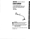
Operator's Manual
CRAFTSMRN
32cc 2-Cycle Engine
18 Inch Cutting Path / .080 In. Line
GASOLINE BRUSHWACKER _
Model No.
358.798461
Read and follow all Safety Rules and Operating
DANGER:
Instructions before first use of this product.
i_)
•
For
to your
questions
this product:
Call answers
7 am-7 pm,
Mon-Sat;
Sun,about
10 arn-7
pm
1-800-235-5878
Sears, Roebuck and Co., Hoffman Estates, IL 60179 USA
530-084336
05/06/96
Warranty Statement
Safety Rules
Assembly
Operation
Maintenance
Service & Adjustments
2
2
5
9
13
14
Storage
TroubleshootingChart
Parts List
Spanish
Parts and Ordering
FULL ONE YEAR
WARRANTY
ON CRAFTSMAN
GAS POWERED
BLADED TRIMMER.
17
18
19
22
Back
BRUSHWACKER
®
For one year from the date of purchase, when this Craftsman Gas Powered
Brushwacker is maintained, lubricated, and tuned up according to the operating
and maintenance instructions in the Operator's Manual, Sears will repair, free of
charge, any defect il_ materials or workmanship.
This warranty excludes the blade, nylon line, spark plug, anci air filter, which are
expendable parts and become worn during normal use.
If this Brushwacker is used for commercial purposes, this warranty applies for only
90 days from the date of purchase. If this Brushwacker is used for rental purposes,
this warranty applies for only 30 days from the date of purchase. This warranty applies only while this product is in use in the United States.
WARRANTY SERVICE IS AVAILABLE BY RETURNING THE BRUSHWACKER'
TO THE NEAREST SEARS SERVICE CENTER IN THE UNITED STATES.
This warranty gives you specific legal rights, and you may also have other rights
which vary from state to state.
Sears, Roebuck and Co., D/817 WA Hoffman Estates, IL 60179
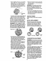
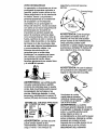
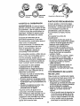
SAFETY NOTICE
DANGER:
This power tool can be
dangerous! This unit can cause serious
injury including amputation or blindness
to the operator and others. The warnings and safety instructions in this manual must be followed to provide reasonable safety and efficiency in using the
unit. The operator is responsible for following the warnings and instructions in
this manual and on the unit. Read the
entire Operator's Manual before assembling and using the unit! Restrict the use
of this unit to persons who read, understand, and follow the wamings and instructions in this manual and on the unit.
Never allow children to use this unit.
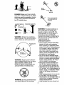
WarningDecal
Exposure to vibrations through prolonged use of gasoline powered hand
tools could cause blood vessel or
nerve damage in the fingers, hands,
and joints of people prone to cimulation disorders or abnormal swellings.
Prolonged use in cold weather has
been linked to blood vessel damage in
otherwise healthy people. If symptoms
occur such as numbness, pain, loss of
strength, change in skin color or texture, or loss of feeling in the fingers,
hands or joints, discontinue the use of
this tool and seek medical attention.
An anti-vibration system does not
guarantee the avoidance of these
problems. Users Who operate power
tools on a continual and regular basis
must monitor closely their physical
condition and the condition of this tool.
Z_
on Tube __f
WARNING: Follow all wamings and
instructions. Failure to do so can result
in serious injury.
2
®
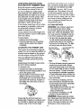
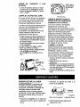
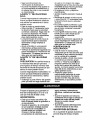
Blade
Coasts
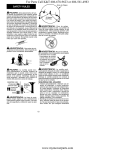
DANGER:
Blade can thrust violently
away from material it fails to cut. Blade
thrust can result in amputation of arms
or legs. Keep people and animals 50
feet (15 meters) away.
ALWAYS WEAR
_
Protection
Eye
II
Leg
II I
Guards
_
Boots
Stop coasting blade
by contact with cut
material.
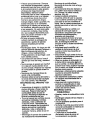
THROWN OBJECTS
WARNING:
Trimmer line can throw
objects violently. You can be blinded or
injured. Wear eye and leg protection.
WARNING: The blade continues to
spin (coast) after the throttle is released or engine is tumed off. The
coasting blade can throw objects or
seriously cut you if accidentally
touched. Stop blade by contacting the
left-hand side of coasting blade with
material already cut.
OPERATOR
Hazard Zone
WARNING:
Hazard zone for thrown
objects. Blade/Trimmer line can throw
objects violently. Others can be
blinded or injured. Keep people and
animals 50 feet (15 meters) away.
WARNING: Do not use trimmer head
as a fastening device for the blade.
SAFETY
• Dress properly. Always wear safety
glasses or similar eye protection
when operating, or performing maintenance on your unit. (Safety glasses
are available.) Always wear face or
dust mask if operation is dusty. Always wear heavy, long pants, long
sleeves, boots, and gloves. Do not
go barefoot or wear sandals.
• Secure hair above shoulder length.
Secure or remove loose clothing and
jewelry or clothing with loosely hanging ties, straps, tassels, etc. They
can be caught in moving parts.
• Being fully covered also helps protect you from debris and pieces of
toxic plants thrown by spinning line.
• Stay Alert. Do not operate unit when
you are tired, ill, or under influence of
alcohol, drugs, or medication. Watch
what you are doing; use common
sense.
• Wear hearing protection if you use unit
for more than 1-1/2 hours per day.
• Never start or run the engine inside a
closed room or building. Breathing
exhaust fumes can kill.
• Keep handles free from oil and fuel.
3
° Always use the handlebar and a
properly adjusted shoulder strap with
a blade. See "Assembly."
UNIT/MAINTENANCE
SAFETY
• Look for and replace damaged or
loose parts before each use. Look for
and repair fuel leaks before use. Keep
the unit in good working condition.
• Throw away blades that are bent,
warped, cracked, broken, or damaged in any other way. Replace trimmer head parts that are cracked,
chipped, broken, or damaged in any
other way before using the unit.
• Maintain the unit according to recommended procedures. Keep the blade
sharp. Keep the cutting line at the
proper length.
• Use only .080" (2 mm) diameter
Craftsman © Pro Trimmer brand line.
Never use wire, rope, string, etc.
• Install the required shield properly before using the unit. Use the metal
shield for all metal blade use. Use the
plastic shield for all line trimmer use.
• Use only specified blade or trimmer
head; make sure it is properly installed and securely fastened.
• Never start engine with clutch shroud
removed. The clutch can fly off and
cause serious injury.
• Be sure blade or trimmer head stops
turning when engine idles.
• Disconnect the spark plug before
performing maintenance (except carburetor adjustments).
• Make carburetor adjustments with
the lower end supported to prevent
the blade or trimmer line from contacting any object. Hold the unit by
hand; do not use the shoulder strap
for support.
• Keep others away when making carburetor adjustments.
• Use only recommended Sears accessories and replacement parts.
• Have all maintenance and service not
explained in this manual performed by
your Sears Service Center.
FUEL SAFETY
• Do not smoke or allow smoking near
fuel or the unit or while using the unit.
• Wipe up all fuel spills before starting
engine.
• Move at least 10 feet (3 meters) away
from fueling site before starting engine.
• Stop engine and allow it to cool before removing fuel cap.
• Empty the fuel tank before storing
the unit. Use up fuel left in the carburetor by starting the engine and letting it run until it stops.
• Store unit and fuel in an area where
fuel vapors cannot reach sparks or
open flames from water heaters, electric motors or switches, furnaces, etc.
CUTTING SAFETY
• Inspect the area to be cut before
each use. Remove objects (rocks,
broken glass, nails, wire, string, etc.)
which can be thrown or become entangled in the blade or trimmer head.
• Keep others including children, animals, bystanders, and helpers at
least 50 feet (15 meters) away. Stop
the engine immediately if you are approached.
• Always keep engine on right-hand
side of your body.
• Hold the unit firmly with both hands.
• Keep firm footing and balance. Do
not overreach.
• Keep blade or trimmer head below
waist level.
• Do not raise the engine above your
waist.
• Keep all parts of your body away
from blade, trimmer head, and muffler when engine is running.
• Cut from your right to your left.
• Use only for jobs explained in this
manual.
TRANSPORTING
AND STORAGE
• Stop the unit before carrying.
• Keep muffler away from your body.
• Allow engine to cool and secure unit
before storing or transporting it in a
vehicle.
• Empty the fuel tank before storing or
transporting the unit. Use up fuel left
in the carburetor by starting the engine and letting it run until it stops.
• Store unit and fuel in an area where
fuel vapors cannot reach sparks or
• Mix and pour fuel outdoors.
• Keep away from sparks or flames.
• Use a container approved for fuel.
4
open flamesfromwater heaters,electric motorsor switches,fumaces,etc.
cannot accidentally cause injury. The
unit can be hung by the tube.
• Store unit out of reach of children.
• Store unit so the blade or line limiter
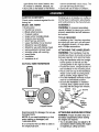
CARTON
CONTENTS
Finding fuel or oil residue on muffler is
normal due to carburetor adjustments
and testing done by the manufacturer.
ASSEMBLY
Check carton contents against the following list.
Model: 358.798461
• Brushwacker
* 2 handle bar screws
• 4 Blade shield screws
• 1 Cupped washer
• 1 large nut for installing blade
• 1 long hex key (wrench)
• 1 short hex key (wrench)
• 1 upper handlebar_over
bracket
• 1 Shield for use with blades
• 1 Shield for use with trimmer head
• 1 semi-automatic
trimmer head
•
•
•
•
WARNING: If received assembled,
repeat all steps to ensure your unit is
properly assembled and all fasteners
are secure.
TOOLS
In addition to
provided with
an adjustable
and a Phillips
the 2 hex key wrenches
your unit, you will need
wrench, or large pliers,
screwdriver.
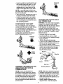
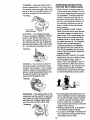
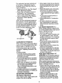
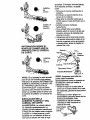
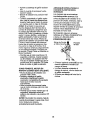
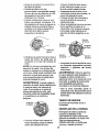
ATTACHING THE HANDLEBAR
WARNING: The handlebar must be
1 shoulder strap with warning
1 weed blade
1 handlebar
1 container of oil
ACTUAL
REQUIRED
installed as shown to provide a barrier
between operator and spinning blade.
• Align the handlebar with the straight
barrier portion to the left and the
curved portion to the right as shown.
• Position the short, straight section of
the handlebar in the mounting block.
• Place cover on top of the handlebar.
Attach cover to the mounting block
with 2 screws; finger tighten only.
• Pivot the handlebar forward or backward to a comfortable position.
• Be sure the handlebar is installed
correctly; then, tighten each screw
securely with the large hex wrench.
SIZE HARDWARE
Screw
Blade
Handlebar
Shield
Screw
Curved
Portion
Large nut for
installing
Blade
1_
_'_'
Grip
_. //.d_
"_--------"_S
Ci_:t r
._,'_-'_._
Cupped Washer
MountingF
ATTACHING
Examine parts for damage. Do not use
damaged parts.
NOTE: If you need assistance or find
parts missing or damaged, call
1-800-235-5878.
It is normal for the fuel filter to rattle in
the empty fuel tank.
Screws
Str "g
_on
SHOULDER
STRAP
WARNING: Proper shoulder strap and
handlebar adjustments before starting
the engine are required.
• Try on shoulder strap and adjust for fit
and balance before starting the engine
or beginning a cutting operation.
5
TRIMMER
HEAD
• Insert your nght arm and head through
the shoulder strap and allow it to rest
on your left shoulder. Make sure the
danger sign is on your back and the
hook is to the right side of your waist.
NOTE: A one-half twist is built in the
shoulder strap to allow the strap to rest
flat on the shoulder.
• Adjust the strap, allowing the hook to
be about 6 inches below the waist.
• Fasten the strap hook to the clamp
located between the foam grip and
the mounting block and lift the tool to
the operating position.
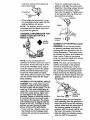
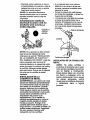
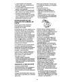
ATTACHING THE PLASTIC SHIELD
AND TRIMMER HEAD
WARNING: The shield must be properly
installed. The shield provides partial
protection from the risk of thrown objects
to the operator and others and is
equipped with a line limiter which cuts
excess line to the proper length. The line
limiter (on underside of shield) is sharp
and can cut you.
CONFIGURING YOUR UNIT
You can configure your unit using a
cutting head for grass and light weeds,
or a weed blade for cutting heavy
weeds and similar size material. Go to
the section for the desired
configuration and follow the instructions for assembling your unit.
• Remove wing nut from shield.
• Insert bracket into slot on shield.
• Pivot shield until bolt passes through
hole in bracket.
TRIMMER
HEAD
• Tighten the wing nut securely.
• If your unit has a plastic cover over the
threads on the threaded shaft, remove
the coveting to expose threads.
• Make sure the dust cup and retaining
washer are positioned on the gearbox as shown below, before installing the trimmer head.
BLADE
WEED
Slot
Bracket
Wing Nut
Gearbox
Shield
DustCup
ASSEMBLY
INFORMATION
USING YOUR UNIT WITH
TRIMMER
HEAD
FOR
A
RetainingWasher
NOTE: If your unit has been assembled for weed blade use, refer to
the section "ASSEMBLY INFORMATION
FOR USING YOUR UNIT WITH A WEED
BLADE" and reverse the steps to remove the metal shield and blade before you mount the plastic shield and
trimmer head.
_j
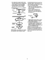
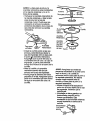
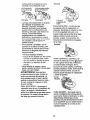
NOTE: Make sure all parts are properly installed as illustrated in the illustration before installing the trimmer head.
• Align hole in the dust cup with the
hole in the side of the gearbox by rotating the dust cup.
• Insert a small screwdriver into
aligned holes. This will keep the
6
shaft from turning while tightening
the trimmer head.
• Place the metal shield under the
gearbox, and align the screw holes.
• Insert the 4 mounting screws through
the bottom of the shield. Thread
them into the gearbox. Tighten evenly and securely with one of the hex
key wrenches provided.
Screwdriver
• While holding the screwdriver in position, thread the trimmer head onto the
shaft and tighten until secure.
NOTE: The retaining washer must be
positioned with the raised section facing toward the gearbox.
Shiel6_,
ASSEMBLY INFORMATION
FOR
USING YOUR UNIT WITH A
WEED BLADE.
_IIN
Gearb°x
Mounting
Screws
BLADE
WEED
ASSEMBLY
OF THE METAL BLADE
WARNING: Do not use any blades,
or fastening hardware other than the
washers and nuts illustrated in the following illustrations. These parts must
be provided by Sears, and installed as
shown below. Failure to use proper
parts can cause the blade to fly off and.
seriously hurt you or others.
NOTE: If your unit has been assembled for trimmer head use, refer to
the section "ATTACHING THE PLASTIC
SHIELD AND TRIMMER HEAD" and reverse the steps to remove the plastic
shield and trimmer head before you
mount the metal shield and blade.
Store these parts for future use. Never
use the trimmer head with the metal
blade installed.
NOTE: The dust cup and retaining
washer are located on the gearbox
and not in the parts bag. It may be
necessary to remove a plastic protective covering from the threaded shaft
before removing the retaining washer.
• Remove the retainer washer from the
gearbox, and leave the dust cup on
the gearbox.
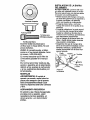
ASSEMBLY OF THE METAL SHIELD
DANGER: The metal shield must be
properly installed on the tool anytime
the tool is used with the blade. The forward top of the metal shield helps to
reduce the occurrence of blade thrust
which can cause serious injury such
as amputation to the operator or by
standers, Failure to install the shield in
the position shown can result in serious injury to the operator. The length
of the shield must be aligned with the
length of the tube. The blade is sharp
and can cut you. Be sure to wear
gloves while working with blades.
• "If your unit has a plastic cover over
the threads on the threaded shaft,
remove the covering to expose the
threads.
Retaining
Washer
Dust Cup _(______..,J"_"
• Install the blade over the threaded
shaft extending from the gearbox between the dust cup and the retaining
washer. Make sure the raised part of
the retaining washer is facing the
gearbox, and the raised area fits into
the hole in the center of the blade.
• Slide the blade and retaining washer
onto the shaft of the gearbox.
7
• Now place the cupped washer onto
wiched between the dust cup and the
retaining washer. There should be no
space between the blade and the dust
cup or the retaining washer.
• Align hole in the dust cup with the
hole in the side of the gearbox by rotating the blade.
• Insert a small screwdriver into
aligned holes. This will keep the
shaft from turning while tightening
the blade nut.
the shaft. Make sure the cupped side
of the washer is toward the blade.
• Install the blade nut by threading
onto the shaft counterclockwise.
_
Threaded _
._D_Dust
Cup _
Shaft
Screwdriver
Reatsa_ne
rng_l"
_
•"l]ghten blade nut firmly witl_ a wrench
while holding screwdriver in position.
• Remove the screwdriver.
• Tum blade by hand. If the blade binds
against the shield, or appears to be
uneven, the blade is not centered, and
you must reinstall the blade.
NOTE: To remove the blade, insert
screwdriver into the aligned holes. Unthread the nut and remove parts. Be
sure to store parts and instructions for
future use.
_
co,,ed
Washer Nut j
NOTE: Make sure all parts are in place
as illustrated, and the blade is sand-
8
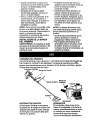
KNOW
YOUR
BRUSHWACKER
READ THIS OPERATOR'S MANUAL AND SAFETY RULES BEFORE OPERATING YOUR
UNIT.Compare the illustrationswith your unit to familiarize yourself with the locationof
the various controls and adjustments. Save this manual for future reference.
On/Stop Switch
Starter
Handle
Throttle Grip
#,
-_
Choke
Handlebar
Primer Bulb
Shield
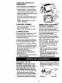
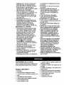
ON/STOP SWITCH
The On/Stop switch is located on the
engine and is used to stop the engine.
Push the switch to the stop position to
stop the unit.
PRIMER BULB
The primer bulb removes air from the
fuel lines and fills them with fuel. This
allows you to start the engine with fewer pulls on the starter rope. Activate
the primer bulb by pressing it and allowing it to return to its original form.
CHOKE
BEFORE STARTING ENGINE
IMPORTANT
WARNING:
Be sure to read the fuel
information in the safety rules before
you begin. If you do not understand
the safety rules, do not attempt to fuel
your unit. Call 1-800-235-5878.
Experience indicates that alcohol
blended fuels (called gasohol or using
ethanol or methanol) can attract moisture which leads to separation and
formation of acids during storage.
Acidic gas can damage the fuel system of an engine while in storage.
FUELING
The choke helps to supply fuel to the
carburetor during starting. This allows
you to start a cold engine. Activate the
choke by moving the choke lever to the
Full pos'_on. After engine has started,
move the choke to the Off position.
ENGINE
This engine is certified to operate on
unleaded gasoline. Before operation,
gasoline must be mixed with a good
quality 2-cycle air-cooled engine oil.
We recommend Craftsman brand oil.
Mix gasoline and oil at a ratio of 40:1
(A 40:1 ratio is obtained by mixing 3.2
ounces of oil with 1 gallon of unleaded
gasoline). DO NOT USE automotive oil
or boat oil. These oils will cause
engine damage. When mixing fuel,
follow instructions printed on container.
To avoid engine problems, empty the
fuel system before storage for 30 days
or longer. Drain the gas tank, start the
engine and let it run until the fuel lines
and carburetor are empty. Use fresh
fuel next season.
Never use engine or carburetor cleaner products in the fuel tank or permanent damage may occur.
See the STORAGE section for additional information.
9
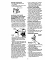
STOPPINGYOUR ENGINE
• Move the On/Stop switch to the
STOP position.
• If engine does not stop, move choke
to the Full Choke position.
On/Stop Switch
STARTING
YOUR
ENGINE
COLD ENGINE OR WARM ENGINE
AFTER RUNNING OUT OF FUEL
WARNING: The blade or trimmer
head will turn while starting the engine.
Avoid any contact with the muffler. A
hot muffler can cause serious burns.
• Rest engine and shield on ground,
supporting trimmer head off ground.
• Move the switch to the On position.
• Slowly press the primer bulb 6 times.
• Move choke to Full Choke position.
Starter
Handle_-_
Choke
• Allow the engine to run 10 seconds,
then move the choke lever to Off
Choke. Allow the unit to run for 30
more seconds at Off Choke before
releasing the throttle trigger.
STARTING A WARM ENGINE
• Move the switch to the on position,
and choke to Half Choke position.
• Squeeze and hold the throttle trigger.
Keep throttle trigger fully squeezed
until the engine runs smoothly.
• Pull starter rope sharply until engine
runs, but no more than 5 pulls.
• Allow engine to run 15 seconds, then
move the choke lever to Off Choke.
NOTE: If engine has not started, pull
starter rope 5 more pulls. If engine still
does not run, it is probably flooded.
DIFFICULT
STARTING
STARTING OR
A FLOODED ENGINE
Flooded engines can be started by
placing the choke lever in the Off
Choke position; then, pull the rope to
clear the engine of excess fuel. This
could require pulling the starter handle
many times depending on how badly
the unit is flooded.
If the unit still doesn't start, refer to the
TROUBLESHOOTING
chart or call
1-800-235-5878.
OPERATING
Throttle
Trigger
Operating
Position
Primer Bulb
• Squeeze and hold the throttle trigger.
• Pull starter rope sharply 5 times.
• Move the choke to the Half Choke
position.
• Continue to hold throttle trigger; pull
starter rope sharply until engine runs,
but no more than 6 pulls.
NOTE: If the engine has not started
after 6 pulls (at half choke), check to
make sure the choke lever is in the
proper position. Then, move the choke
to the Full Choke position and press
the primer bulb 6 times. Squeeze and
hold the throttle trigger and pull the
starter rope 2 more times. Move the
choke lever to Half Choke and pull the
starter rope until the engine runs, but
no more than 6 more pulls. If the engine still has not started, it is probably
flooded. Proceed to "Starting a
Flooded Engine."
POSITION
Right Hand on
Throttle Grip
• Left arm extended with hand holding
the handlebar grip.
• Right hand on throttle grip with fingers on throttle trigger.
• Engine below waist level.
• Shoulder strap pad centered on left
shoulder, danger sign centered on
your back.
• Full weight of unit on left shoulder.
• Without operator bending over, the
blade or semi-automatic head is near
and parallel to the ground and easily
contacts material to be cut.
10
OPERATING INSTRUCTIONS
FOR USE WITH TRIMMER HEAD
Bring the engine to cutting speed before entering the material to be cut.
Do not run engine at a higher speed
than necessary. The cutting line will cut
efficiently when the engine is run at less
than full throttle. At lower speeds, there
is less engine noise and vibration. The
cutting line will last longer and will be
less likely to "weld" onto the spool.
If the trimmer head does not turn when
the engine is in operation, make sure
the drive shaft housing is properly
seated in engine shroud.
Always release the throttle trigger and
allow the engine to return to idle speed
when not cutting.
To stop engine:
• Release the throttle trigger.
• Push and hold down the momentary
switch until the engine has stopped
completely.
ADVANCING
THE TRIMMER
LINE
The trimmer line will advance approximately 2 in. (5 cm) each time bottom of
trimmer head is tapped on the ground
with the engine running at full throttle.
The most efficient line length is the
maximum length allowed by the line
limiter.
Always keep the shield in place when
the tool is being operated.
To Advance Line:
• Operate the engine at full throttle.
• Hold the trimmer head parallel to and
above the grassy area.
• Tap the bottom of the trimmer head
lightly on the ground one time. Approximately 2 in. (5 cm) of line will be
advanced with each tap. A blade on
the shield will cut the line to the correct length.
Always tap the trimmer head on a
grassy area. Tapping on surfaces such
as concrete or asphalt can cause excessive wear to the trimmer head.
If the line is wom down to 2 in. (5 cm) or
less, more than one tap will be required
to obtain the most efficient line length.
WARNING:
Use only .080" (2 mm)
diameter line. Other sizes of line will
not advance properly and can cause
serious injury. Do not use other materials such as wire, string, rope, etc. Wire
can break off during cutting and become a dangerous missile that can
cause serious injury.
CUTTING
METHODS
WARNING:
Use minimum speed and
do not crowd the Finewhen cutting
around hard objects (rock, gravel, fence
posts, etc.), which can damage the trimmer head, become entangled in the Fine,
or be thrown causing a serious hazard.
• The tip of the line does the cutting.
You will achieve best performance and
minimum line wear by not crowding
the line into the cutting area. The right
and wrong ways are shown below.
Line Crowded Into
Tip of the Line
Work Area
Does The Cutting
:i"!':::::
Right
Wrong
• The line will easily remove grass and
weeds from around walls, fences,
trees and flower beds, but it also can
cut the tender bark of trees or shrubs
and scar fences. To help avoid damage especially to delicate vegetation
or trees with tender bark, shorten line
to 4-5 in. (10-13 cm) and use at less
than full throttle.
• For trimming or scalping, use less
than full throttle to increase line life
and decrease head wear, especially:
• During light duty cutting.
• Near objects around which the line
can wrap such as small posts,
trees or fence wire.
• For mowing or sweeping, use full
throttle for a good clean job.
WARNING: Always wear eye protection. Never lean over the trimmer head.
Rocks or debris can ricochet or be
thrown into eyes and face and cause
blindness or other serious injury.
11
TRIMMING - Hold the bottom of the
trimmer head about 3 in. (8 cm) above
the ground and at an angle. Allow only
the tip of the line to make contact. Do
not force trimmer line into work area.
Trimming
3 ibnov(8(_rmo)un_;_
_.._;_i' _ t_
SCALPING - The scalping technique
removes unwanted vegetation. Hold the
bottom of the trimmer head about 3 in.
(8 cm) above the ground and at an angle. Allow the tip of the line to strike the
ground around trees, posts, monuments,
etc. This technique increases line wear.
Scalping
MOWING - Your trimmer is ideal for
mowing in places conventional lawn
mowers cannot reach. In the mowing
position, keep the line parallel to the
ground. Avoid pressing the head into
the ground as this can scalp the
ground and damage the tool.
Mowing
,.
• Blade Thrust is a reaction that only
occurs when using a blade. This reaction can cause serious injury such
as amputation. Carefully study this
section. It is important that you understand what causes blade thrust,
how you can reduce the chance of
its occurring, and how you can remain in control of the unit if blade
thrust occurs.
• WHAT CAUSES BLADE THRUST
Blade Thrust can occur when the spinning blade contacts an object that it
does not cut. This contact causes the
blade to stop for an instant .and then
suddenly move or "thrust" away from
the object that was hit. The "thrusting"
reaction can be violent enough to
cause the operator to be propelled in
any direction and lose control of the
unit. The uncontrolled unit can cause
serious injury if the blade contacts the
operator or others.
• WHEN BLADE THRUST OCCURS.
Blade thrust can occur without waming if the blade snags, stalls, or
binds. This is more likely to occur in
areas where it is difficult to see the
material being cut. By using the unit
properly, the occurrence of blade
thrust will be reduced and the operator will be less likely to lose control.
-....
SWEEPING - The fanning action of the
rotating line can be used for a quick and
easy clean up. Keep the line parallel to
and above the surfaces being swept
and move the tool from side to side.
Sweeping
OPERATING INSTRUCTIONS
FOR USE WITH WEED BLADE
• Cut only grass and weeds up to 1/2
inch in diameter with the weed blade.
Do not let the blade contact material
it cannot cut such as stumps, rocks,
fences, metal, etc., or clusters of
hard, woody brush having a diameter
greater than 1/2 inch.
• Keep the blade sharp. A dull blade i_
more likely to snag and thrust.
• Cut only at full throttle. The blade will
have maximum cutting power and is
less likely to bind or stall.
12
• "Feed" the blade deliberately and not
too rapidly. The blade can thrust
away if it is fed too rapidly.
* Cut only from your right to your left.
Swinging the unit in the same direction as the blade spins increases the
cutting action.
• Use the shoulder strap and keep a
firm grip on the unit with both hands.
A properly adjusted shoulder strap
will support the weight of the unit,
freeing your arms and hands to control and guide the cutting motion.
• Keep feet comfortably spread apart
and braced for a possible sudden,
rapid thrust of unit. Do not overreach.
Keep firm footing and balance.
• Keep blade below waist level; it will
be easier to maintain control of unit.
• Do not raise the engine above your
waist as the blade can come dangerously close to your body.
• Do not swing the unit with such force
that you are in danger of losing your
balance.
Bring the engine to cutting speed before entering the material to be cut.
If the blade does not tum when you
squeeze throttle trigger, make sure drive
MAINTENANCE
shaft tube is fully inserted into engine.
Always release the throttle trigger and
allow engine to return to idle speed
when not cutting. The blade should not
turn while the engine is running at idle.
If the blade turns at idle, do not use
your unit. Refer to the Carburetor adjustment section or contact your Sears
Service Center.
• Maintain firm footing while using the
unit. Firmly plant feet comfortably
apart.
• Cut while swinging the upper part of
your body from right to left.
• As you move forward to the next
area to cut, be sure to maintain your
balance and footing.
10 o'clock
Cut using the 8 o'clock
to 10 o'clock
the blade
WARNING: To avoid serious injury,the
operator or others must not try to clear
away cut material with the engine running or the blade tuming. Stop engine
and blade before removing materials
wrapped around the blade or tube.
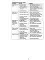
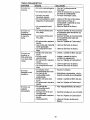
SCHEDULE
CARE & MAINTENANCE
TASK
WHEN TO PERFORM
Check for Loose fasteners
and parts
Before each use
Before each use
Check for damaged or worn parts
Clean unit and labels
After each use
Clean air filter
Every 5 hours of operation
Inspect and clean spark arrestor
Replace spark plug
Every 25 hours of operation
Yearly
GENERALRECOMMENDATIONS
The warranty on this unit does not cover items that have been subjected to
operator abuse or negligence. To receive full value from the warranty, the
operator must maintain unit as instructed in this manual. Various adjustments
will need to be made periodically to
propedy maintain your unit.
CHECK FOR LOOSE
FASTENERS AND PARTS
•
•
•
•
•
13
Spark Plug Boot
Air Filter
Housing Screws
Assist Handle Screws
Shield
CHECK FOR DAMAGED OR
WORN PARTS
Air Filter
Refer replacement or damaged/worn
parts to your Sears Service Center.
Cover
\
• On/Stop Switch - Ensure On/Stop
switch functions properly by moving
the switch to the "Stop" position.
Make sure engine stops; then restart
engine and continue.
• Fuel Tank - Discontinue use of unit if
fuel tank shows signs of damage or
leaks.
• Shield- Discontinue use of unit if
shield is damaged.
Screws
Back
view of
Air Filter
Cover
J
Air Filter
CLEAN UNiT & LABELS
• Clean the unit usin_g a damp cloth
with a mild detergent.
• Wipe off unit with a clean dry cloth.
CLEAN AIR FILTER
Do not clean filter in gasoline or other
flammable solvent; doing so can
create a fire hazard or produce harmful
evaporative emissions.
A dirty air filter decreases engine perforrnance and increases fuel consumption and harmful emissions. Always
clean after every 5 hours of operation.
• Clean the cover and the area around
it to keep dirt and debris from falling
into the carburetor chamber when
the cover is removed.
• Remove parts as illustrated.
• Wash the filter in soap and water.
• Allow filter to dry.
• Replace parts, making sure the filter
is seated completely.
REPLACING
THE LINE
WARNING: Trimmer head parts that
are chipped, cracked, broken, or damaged in any other way can fly apart and
cause serious injury.Do not use. Replace damaged parts before using unit.
• Press the tab on the side of the trimmer head and twist the lock ring.
• Remove the lock ring and tap button.
• Pull spool out of the trimmer head.
• Clean dirt and debris from all parts.
INSPECT
AND CLEAN SPARK
ARRESTOR (if equipped)
As the unit is used, carbon deposits
build up on the muffler and spark
arrestor screen, and must be removed
to avoid creating a fire hazard or affecting engine performance.
Remove the spark arrestor screen
from the muffler and clean. Replace
spark arrestor screen if breaks occur.
REPLACE
SPARK PLUG
Replace the spark plug each year to
ensure the engine starts easier and
runs better. Set spark plug gap at
.025 in. Ignition timing is fixed and
nonadjustable.
• Twist, then pull off spark plug boot.
• Remove spark plug from cylinder
and discard.
• Replace with Champion RCJ-8Y
spark plug and tighten with a 3/4 in.
socket wrench (10-12 ft.-Ibs).
• Reinstall the spark plug boot.
• Replace with a pre-wound spool, or
replace line using 40 feet of .080" (2
ram) diameter Craftsman ® Pro Trimmet line.
Trimmer
Tap Button
14
Lock Ring
• When installing new line on an existing
spool, insert 1116" of the line into the
anchoring hole in the bed of the spool,
and wrap the line evenly and firmly
around the spool in the direction of the
arrow found on the spool.
• Make sure the lock ring is securelytastened by pulling on it and twisting in
both directions.
WARNING: All catches must be fastened and the lock tab latched in the
lock ring. If installed incorrectly, the
lock ring can fly off and become a dangerous missile.
• Pull the line extending from the trimmer head. This will allow the spool in
side the trimmer head to release from
the locked position.
• Insert the end of the linethrough the exit
hole in the side of the trimmer head.
NOTE: A metal insert is located in the
exit hole. As your unit wears from use,
you can re-install this insert upside
down to provide a new surface for the
exit of the line from the trimmer head.
WARNING:
When installing the metal
insert, you must install from the inside of
the trimmer head. If installed on the outside of the trimmer head, this insert can
fly off and become a dangerous missile.
IGNITION
TIMING
Ignition timing is fixed and non-adjustable.
SPOOL REPLACEMENT
Replace the spool when the square
comers on the lugs are rounded off,
reduced in size, or broken. Follow
instructions under REPLACING THE
LINE for removing and installing spool.
Metal Insert
• Once the line is passing through exit
hole, place spool in the trimmer head.
Press the spool down and turn the
spool until it locks down and does not
pop up when you release it.
• Make sure.the line is not caught between the rim of the spool and the
wall of the trimmer head.
• Replace the tap button, and place
the lock ring onto the trimmer head.
• Align lock ring over the catches on the
trimmer head. Push the ring down and
turn until the catches lock into place.
Catch
Catch
Lock
Tab
Catch
Catch
_ormal
lug
CARBURETOR
ADJUSTMENT
WARNING: The trimmer head will be
spinning during most of this procedure.
Wear your protective equipment and
observe all safety precautions. After
making mixture adjustments, recheck
idle speed.
Carburetor adjustment is critical and if
done improperly can permanently
damage the engine as well as the carburetor. If you require further assistance or are unsure about performing
this procedure, call our customer assistance help line at 1-800-235-5878.
Old fuel, a dirty air filter, a dirty fuel filter, or flooding may give the impression of an improperly adjusted carburetor. Check these conditions before
adjusting the carburetor.
15
The carburetor has been carefully set
at the factory. Adjustments may be
necessary if you noticeany of the following conditions:
• Engine will not idle. See "Idle Speed"
under adjusting procedure.
• Engine dies or hesitates instead of
accelerating. See "Acceleration
Check" under adjusting procedure.
• Loss of cutting power. See "Mixture
Adjustment" under adjusting
procedure.
There are three adjustment screws on
the carburetor. The low speed adjustment screw is marked with the letter L,
and the high speed adjustment screw
is marked with the letter H. The third
screw is the idle adjustment screw.
L Screw
H Screw
Idle Adjustment
CARBURETOR
PRESETS
When making carburetor preset adjustments, do not force plastic limiter caps
beyond stops or damage will occur.
If carburetor presets are not needed,
proceed to "Adjusting Procedure, Idle
Speed."
To adjust presets:
• Turn both mixture screws counterclockwise to the midpoint between
the limiter cap stops.
•Tum the idle speed screw clockwise
until it stops. Now turn counterclockwise 4-1/2 turns.
• Start motor, cut grass for 3 minutes,
and proceed to the adjustment section. If engine does not start,
refer to troubleshooting chart or call
1-800-235-5878.
• If engine performance is acceptable
at the preset positions, no further adjustment is necessary.
ADJUSTING
PROCEDURE
Idle Speed Adjustment
Allow engine to idle. Adjust speed until
engine runs without stalling.
• Allow engine to idle. Be sure the trimmer line is extended to the maximum
length allowed by the blade on the
shield.
• Adjust idle speed screw until engine
continues to run without stalling.
• Turn screw clockwise to increase
engine speed if the engine stalls or
dies.
• Turn screw counterclockwise to
slow engine down.
• Follow instructions in "Acceleration
Check".
• No further adjustments are necessary if performance is satisfactory
and the trimmer head does not turn
at idle.
Low Speed Adjustment "L"
When making carburetor adjustments,
do not force plastic limiter caps beyond
stops or damage will occur.
• Allow the engine to idle.
• Turn screw "L" slowly clockwise until
the speed begins to drop. Note the
position of the screw. Do not attempt
to adjust beyond the stops as damage can occur.
• Slowly turn the screw counterclockwise until the speed increases and
then begins to drop.
• Adjust the screw to the midpoint between the two positions.
• Check the acceleration by following
the steps outlined under ACCELERATION CHECK. The trimmer head must
not turn at idle speed.
High Speed
Adjustment
"H"
CAUTION: Do not operate engine at
full speed for prolonged periods while
making mixture adjustments as damage to the engine can occur.
When making carburetor adjustments,
do not force plastic limiter caps beyond
stops or damage will occur.
• Support the lower end of the unit off
the ground so cutting attachment will
not make contact with any objects.
Be sure the trimmer line is extended
to maximum length allowed by the
blade on the shield.
• Start the engine and allow to idle.
• Squeeze the throttle trigger fully.
• Keep the unit running a full speed,
and turn the screw "H" very slowly
1R
clockwise until the speed begins to
slow down.
• Do not let go of the throttle trigger,
and turn screw counterclockwise
until the engine begins to run roughly.
• Still holding the throttle trigger, turn
the screw slowly a small amount until
the engine begins to run smoothly.
• Check the acceleration by following
the steps outlined under ACCELERATION CHECK. The trimmer head must
not turn at idle speed.
Acceleration
Check
• Allow engine to idle. Be sure the trim-
Prepare unit for storage at end of season or if it will not be used for 30 days
or more.
WARNING:
• Allow engine to cool, and secure the
unit before storing or transporting.
• Store unit and fuel in a well ventilated area where fuel vapors cannot
reach sparks or open flames from
water heaters, electric motors or
switches, furnaces, etc.
• Store unit with all guards in place.
Position unit so that any sharp object
cannot accidentally cause injury.
• Store unit and fuel well out of the
reach of children.
EXTERNALSURFACES
If your unit is to be stored for a period
of time, clean it thoroughly before storage. Store in a clean dry area.
• Lightly oil external metal surfaces.
FUEL
SYSTEM
Under Fueling Engine in the Operating
Section of this manual, see message
labeled IMPORTANT regarding the use
of gasohol in your engine.
Fuel stabilizer is an acceptable alternative in minimizing the formation of
fuel gum deposits during storage. Add
mer line is extended to the maximum
length allowed by the blade on the
shield.
• Squeeze trigger fully: If the engine
does not accelerate smoothly, turn
screw "rE_"
counterclockwise a sma]l
amount (no more than the width of the
slot in the adjusting screw). Do not attempt to adjust the screws beyond the
stops as damage can occur.
• Repeat above steps until smooth acceleration is obtained. Do not attempt to adjust the screw beyond the
stops as damage can occur.
stabilizer to the gasoline in the fuel
tank or fuel storage container. Follow
the mix instructions found on stabilizer
container. Run engine at least 5 minutes after adding stabilizer.
CRAFTSMAN 40:1,2-cycle
engine oil
(air cooled) is already blended with
fuel stabilizer. If you do not use this
Sears oil, you can add a fuel stabilizer
to your fuel tank.
INTERNAL
ENGINE
• Remove spark plug and pour 1 teaspoon of 40:1, 2-cycle engine oil (air
cooled) through the spark plug opening. Slowly pull the starter rope 8 to
10 times to distribute oil.
• Replace spark plug with new one of
recommended type and heat range.
• Clean air filter.
• Check entire unit for loose screws,
nuts, and bolts. Replace any damaged, broken, or worn parts.
• At the beginning of the next season,
use only fresh fuel having the proper
gasoline to oil ratio.
OTHER
• Do not store gasoline from one season to another.
• Replace your gasoline can if it starts
to rust.
17
TROUBLESHOOTING
TROUBLE
Enginewillnot
stad.
Engine will not
idle properly.
CHART
REMEDY
CAUSE
_-Engineflooded.
•Fueltankempt_
• Spark plug not firing.
• Fuel not reaching
carburetor.
•
•
•
•
i • Compression low.
• Idle speed set too low.
• Idle speed set too high.
• Carburetor requires
adjustment.
• Crankshaft seals worn.
,• _Compression low.
Engine will not
accelerate,
lacks power,
or dies under
a load.
Engine smokes
excessively.
See "Starting Instructions."
Fill tank with correct fuel mixture.
Install new spark plug.
Check for dirty fuel filter; replace.
Check for kinked or split fuel line;
repair or replace.
• Contact Sears Service.
• Adjust idle speed screw
clockwise to increase speed.
• Adjust idle speed screw counterclockwise to reduce speed.
• See "Carburetor Adjustments."
• Contact Sears Service.
• Contact Sears Service:
• Clean or replace air filter.
• Clean or replace spark plug
and re-gap.
• See "Carburetor Adjustments."
i" Air filter dirty.
I • Spark plug fouled.
• Carburetor requires
adjustment.
• Carbon build up.
• Compression low.
• Contact Sears Service.
• Contact Sears Service.
• Choke partially on.
• Fuel mixture incorrect.
• Air filter dirty.
• Carburetor requires
adjustment.
Engine runs hot. • Fuel mixture incorrect.
• Spark plug incorrect.
• Carburetor requires
adjustment
• Carbon build up.
18
• Adjust choke.
• Empty fuel tank and refill with
correct fuel mixture.
• Clean or replace air filter.
• See "Carburetor Adjustments."
• See "Fueling Your Unit."
• Replace with correct spark plug.
• See "Carburetor Adjustments."
• Contact Sears Service.
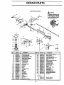
REPAIR PARTS
SEARS MODEL 358.798461
A
All repairs, adjustments and
maintenance not descrlped
In the Operator's
Manual
32
•
4O
WARNING
/_
13
37
3
6
_L__
23
31
_
16---I1
17--111
18.---_
rv
42
44
Raf.
1,
2.
•
3.
4,
5.
6,
7.
8,
9.
10,
11.
12.
13.
14.
15.
16,
17,
18,
19.
20.
21.
241
25,
26.
Pllrl NO.
830037497
530069781
STD541025
830069674
530016107
7185807
830O277O6
530069252
530069779
530015808
53O095387
530016166
534235S01
530016119
530093896
53O093898
53O34O007
530O92O68
530095121
7185787
530401183
53(X_2133
530095409
530094585
530015820
530049211
Description
Ref.
Throttle Cable Ass'y.
Ddve Shaft Housing
Nut-Shoulder Ham. Clamp
Handlebar w/Decal
• Screw-Clamp Handlebar
Cutting Head Ass'y,
27.
28.
29,
30.
31.
32,
DriveShaft Pad
Handle ASS'),.
ShieldKitAss'y.
(IncL10, 11)
Umiter
Une Umiter
DustCup
I.oc_ut
Knob
HubAss'y,(Incl.16)
33,
34.
35.
36,
37.
38.
39.
40.
41.
42.
43,
44.
45.
46,
47.
Une Saver
Spdng
Cad-Spring
Drive Gear
Spoot w/Une
Release Button
Cover
Gear Box Ass')'.
Drive Shaft
Bolt
Decal--81ade Direction
Part No.
53OO27884
530016140
530015328
530047469
530015650
530015775
530047468
530092086
530094572
530012207
530O94666
530094417
530016141
530047329
530069780
530031159
7185729
530031098
530016167
530015492
530015793
Dee¢dptlon
Decal-Handlebar Wsmlng
Scmw=Locator
Lockwacher-Loc_ztor
Decal-Shaft Warning Lower
Screw-Pinch Clamp
Screw
Dec,aI-Shaft Waming Upper
Grip-Handlebar
Handlebar Bracket
Handlebar Clamp
Clamp Hsmess Ass'y.
Shoulder Strap
Scmw
Throttle Lever Ass'),.
Shield-Metal
Hex Wrench (5/32)
WeedBlade
HexWrench(3/16)
Wacher-Blade Retaining
Washer,--B
ellavillaBalde
Nut-Blade
Not Shown
53O084336
952O30139
19
Operator Manual
Shaft Lubrication
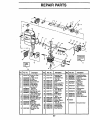
REPAIR PARTS
51
20
43
30
47
42
44
26
48
Fief,
1.
Part No.
530015773
3.
4.
5.
6.
7.
8.
530027529
530027530
530015849
530015852
530015254
530038915
53003793O
g"
530069247
10,
11.
530069571
530014362
530069651
12,
13,
14.
15,
530019156
530014347
530047538
530019154
16.
17.
18.
530027593
530027594
530014015
19.
530010960
2.
Oascdptlon
Scraw-Air Rlter Cover
Air Fitter Cover
Air Fitter
Screw-Carb.
Spacer-Air Fitter
Wave Washer
Choke Shutter
Air Fitter Plate
Fuel Line Kit
! Fuel Une
Return Une
Fuel Pick-up Ass'y.
Carburetor Kit
(Incl. Llmtter Caps)
Carburetor Gasket
Fuel Cap Asa'y.
Shroud & Tank Ass'y.
Crankcase/Shroud
Gasket
Reed Valve
Reed Stop
C'cese/Crankahaft
Ass'y, (Incl. 20, 21,
28, & 36-39)
Connecting Rod
Ass'),.
Raf.
Part No,
20.
530015789
21,
530010934
22.
23.
24.
25.
26.
27.
28,
530015126
530015771
530015780
530027546
530015239
530015772
530014016
; 2g.
530015717
i 30.
31.
530047541
STD610603
32.
33,
34.
35.
530015162
530025875
530019178
53O_69275
36.
37.
38.
39.
530032103
530015787
530019158
530032102
Deacflptlon
Retaining RingCrankshaft
Crankshaft Ass'y.
(Incl. 36)
Ftywheel Kay
Screw
Screw-Lead Wire
Switch Insulator
Scmw-Cycfinder
Screw
Crankcase Ass'y.
(Incl. 36-39)
Scraw-Muffler
Guard
Muffler Guard
Scraw-Rued
Valve
Piston Pin Rat.
piston Ring
Cytlnder Gasket
Piston Kit
(Incl. 32, 33 & Pin)
Inner Bearing
Retaining Ring
I Crankshaft Seal
i Outer Beadng
2O
Ref.
Part No.
40.
41.
42.
43.
530038874
530016091
530069257
530036409
44.
45.
5.30(_9626
Champion
46.
530039134
47.
530015128
48,
530069276
49.
50.
51.
530027547
530027545
530047319
Description
Primer Bulb Ass'),.
Screw-Primer Bulb
Muffler Kit
Muffler Attachment
Spring
Cylinder Kit
Spad_ Plug
(RCJ.-aY)
Ignition Module
Kit
Screw.Ignition
Module
Engine Gasket Kit
(Irml,
12,15& 34)
Lead Wire
SwitchRamp
SwitchSpringAss'y,
Not Shown
530038919
Instructk_nDecal
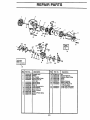
REPAIR PARTS
6
21
10
12
19
18
15
17
16
14
24
KIT
KIT
15
KIT
22
KIT
Repair Kit
Carburetor
(KIT=
Contents) I
KIT
KIT
KIT
\
23
ReL
Part No.
2.
3.
4.
5.
530039189
53O347987
53OO47997
53OO16O80
530069291
6.
7.
8,
9,
10.
11.
12,
13,
14,
15,
530029395
530027569
53006_32
530_69784
530094189
530_9254
530069785
530015767
530015768
530015770
I,
Detmdptlon
Ref.
Part No.
FIp,,h_ A_s'y,
16,
17.
18.
19.
20.
21.
22,
23.
STD541137
530015796
530_7523
530015496
530015769
530027511
952701612
530069623
24.
25.
530038318
530038317
Washer
Fan Housing
Screw-Starter Pulley
Starter Pulley Kit
(Incl. 45)
Starter Spring
Starter Handle
Rope KIt
Pulley Housing Ass'y.
Clutch Washer
Clutch Ass'y. Kit
Clutch Housing
Screw
Locknut.-Rnch Clamp
Screw
21
Detw.,rlptlofl
Nut
Washer-Belleville
Retainer-Starter Pulley
Screw
Screw
Specer.-.Flywhee[
Spark Arrestor Kit
Carburetor Repair Kit
(KiT=Contents)
Um_tar Cap-High Speed
LimitarCap-Low Speed
Declaraci6n de Garantfa
Reglas de Seguridad
Montaje
Uso
Mantenimiento
22
22
25
30
36
Servicio y Ajustes
AImacenaje
Tabla Diagn6stica
Piezas de Repuesto y
Encomiendas
37
40
42
Contratapa
GARANTIA COMPLETA DE UN AI_IO PARA LA CORTADORA DE
MALEZA A GASOLINA, BRUSHCUTTER DE CRAFTSMAN.
Durante un aSo completo, a partir de la fecha de compra, siempre que
se haga el mantenimiento, la lubdcacibn y los ajustes, a esta Cortadora
de Maleza a Gasolina Brushcutter de Craftsman segun las instrucciones
de uso y mantenimiento en el manual del usuario, Sears reparard
cualquier defecto de matedales o de mano de obra gratuitamenteo
Esta garantfa excluye la cuchilla, la Ifnea de nil6n, la bujfa y el filtro del
aire, que son piezas fungibles que se gastan con el uso normal.
Si se usa esta Cortadora de Maleza a Gasolina Brushcutter de Craftsman
para fines cornerciales, esta garantfa tendr_, validez solamente por 90 dfas
a partir de la fecha de compra. Si se usa esta Cortadora de Maleza a
Gasolina Brushcutter de Craftsman para fines de alquiler, esta garantfa
tendr_, validez solamente por 30 dlas a partir de la fecha de compra. Esta
garantfa tendrd validez 0nicamente mientras se use este producto dentro
de los Estados Unidos.
SE OBTENDRA SERVICIO BAJO GARANTIA DEVOLVIENDO LA
CORTADORA DE MALEZA BRUSHCU'I-I'ER DE CRAFTSMAN AL
CENTRO DE SERVICIO DE SEARS MAS CERCANO EN LOS
ESTADOS UNIDOS.
Esta garantfa confiere derechos legales especfficos al propietario, que
tal vez tenga asimismo otros derechos que varfan entre estados.
Sears, Roebuck y Co. Dept. D/817WAHoffman States, IL 60179
ADVERTENCIA:
i Esta herramienta
de fuerza puede ser peligrosa] Este
aparato puede causar accidentes muy
serios, incluyendo ceguera o la
amputaci6n de alguno de los
miembros del cuerpo al usuario o a
otras personas. Los avisos de peligro
y las reglas de seguddad en este
manual deberdn ser seguidos para asf
proveer seguridad razonable y
eficiencia al usar el aparato. El usuario
es responsable de seguir las
advertencias e instrucciones en este
manual y en el aparato, iLea el
Manual del Usuario en su totalidad
antes de montar o de usar el aparato!
Limite el uso de este aparato a
aquellas personas que hayan lefdo y
comprendido, y que vayan a seguir
todas las advertencias e instrucciones
tanto en et aparato como en el
manual. No permita nunca a los niSos
que usen este aparato.
Calcomania
con SeSal de
.,_.,_.,_.,_.,_.,_._,_/
Advertencia _
ADVERTENClA: Siga todas las
advertencias e instrucciones, de no
hacedo asf, podrfan ocurrir accidentes
lamentables.
AVISO DE SEGURIDAD
La exposici6n a vibraciones por el uso
prolongado de aparatos manuales a
gasolina, podrfa causar dafios en los
vasos sangufneos o en los nervios de
los dedos, manos y coyunturas a
personas propensas a los trastomos
de circulaci6n o a hinchazones
anormales. El uso prolongado en
tiempo de clima frfo, ha sido asociado
con dafios a los vasos sangufneos de
personas que por otra parte se
encuentran en perfecto estado de
salud. Si ocurrieran sfntomas tales
como entumecimiento, dolor, falta de
fuerza, cambios de color o textura de
la piel o falta de sentido en los dedos,
las manos o en las coyunturas, deje
de usar esta mdquina inrnediatamente
y procure atenci6n m_lica. Los
sistemas de antivibraci6n no
garantizan que se eviten tales
problemas. Los usuados que hacen
uso continuo y prolongado de las
herramientas de fuerza, deben
fiscalizar atentamente su estado ffsico
y el est=di_'del aparato.
seguddad y protecci6n para las
piernas.
Zona de Peligro
ADVERTENClA:
Zona de peligro
para objetos arrojados al aire. La
cuchilla o la Ifnea de corte pueden
armjar objetos al aire violentamente.
Otras personas podrfan sufrir
accidentes o quedar ciegos. Mantenga
a personas y animales 15 metros (50
pies) alejados de la zona de trabajo.
ADVERTENCiA:
No use el cabezal
de la podadora como disp0sitivopara
regular la velocidad de la cuchilla.
®
ADVERTENCIA:
La cuchilla puede
moverse violentamente en sentido
contrario de materiales que no puede
cortar. Este movimiento podrfa causar
la amputaci6n de los brazos y las
piemas. Mantenga alejadas a otras
personas y animales por Io menos 15
metros (50 pies) de la zona de trabajo.
SIEMPRE USE I OBJETOS ARROJADOS
Paradetener la cuchilla
cuando esta se encuentra
rodandosin impulso,p6ngala
en contacto con el matedal
que ya se ha cortado
ADVERTENClA:
La cuchilla
continuard girando despuds de soltar
el acelerador o despuds de apagar el
motor. La cuchilla girante puede
_
Protscci6nparaOjosParapiemasPmtecci6nlaslOS
[mill
AL AI_E_.
arrojar objetos al aire o si
accidentalmente se toca podrfa causar
serias cortaduras, detenga la cuchilla
ADVERTENCIA:
La Ifnea de corte
poniendo en contacto la parte
izquierda de la cuchilla girante con el
puede arrojar objetos al aire
material que ya se ha cortado.
violentamente. Usted podrfa quedar
SEGURIDAD DEL USUARIO
ciego o herido. Use anteojos de
8o= I
• Vistase apropiadamente.
Siempre
use anteojos de seguridad o similar
protecci6n para los ojos cuando use
o d6 mantenimiento
a este aparato.
(Anteojos de Seguridad estdn
disponibles). Siempre utilize
mascarilla para la cara o mascadlla a
prueba de polvo si se va a trabajar
en condiciones donde hay polvo.
Siempre use pantalones largos,
mangas largas, botas y guantes. No
trabaje descalzo ni en sandalias.
• Mantenga el cabello pot encima de
los hombros, atdndolo para tal efecto
si es necesario. No use ropa suelta
ni ropa con corbatas, tiras, borlas,
etc. que cuelguen libremente pues
estas se pueden enredar en las
piezas en movimiento.
• El tener el cuerpo totalmente
cubierto tambi_n le protegerd de
escombros y partes de plantas
t6xicas arrojadas pot la I_nea
giratoria.
• Mant_ngase alerta. No haga uso del
aparato estando cansado, enfermo o
bajo la influencia del alcohol, de
drogas u otros medicamentos.
Ponga atenci6n a Io que haga y use
buen sentido com6n.
• Use protecci6n de oidos si usa el
aparato por m&s de hora_ y media al
dia.
__ ,• Nunca ponga el aparato en mar€ha"
ni Io deje en marcha dentro de un
recinto cerrado. Respirar los vapores
de combustible le puede causar la
muerte.
• Mantenga los mangos libres de
aceite y de combustible.
• Siempre utilize la barra del manto y
la banda del hombro bien ajustada
con una cuchilla. Vea =Montaje'.
SEGURIDAD
DEL APARATO Y EN
EL
• Inspeccione el aparato y cambie las
piezas daSadas o flojas antes de
cada uso. Repare toda fuga de
combustible antes de usar el
aparato. Mantenga el aparato en
buenas condiciones de uso.
• "13rea la basura las cuchiUas que se
encuentren dobladas, torcidas,
astilladas, rotas o daSadas de
cualquier forma. Reemplaze las
partes del cabezal de la podadora
que se encuentren quebradas,
astilladas, rotas o daSadas de
cualquier manera, antes de uar el
aparato.
• Mantenga el aparato de acuerdo con
las indicaciones recomendadas.
Mantenga la cuchilla afilada.
Mantenga la Iinea de corte el largo
apropiado.
• Use solamente Ifnea de di_,metro 2
mm (.080") de la marca Craftsman
Pro Trimmer. No utilize cuerda,
alambre, hilo, etc,
• Instale la cubierta protectora
requerida antes de usar su aparato.
Use la cubierta protectora de metal
para todo el uso con cuchUlas de
metal. Use la cubierta protectora de
pldstico para todo el uso con I_nea
de corte.
• Utilize solamente la cuchilla o el
cabezal de corte que aqul se
especifican; asegurese que estdn
instalados apropiadamente y
ajustados con seguridad.
• Nunca encienda el motor si la tapa
del embrague no se enctmntra en su
sitio. El embrague poddd ser
arrojado al aire y causar accidentes
muy serios.
• Asegemse que la cuchilla o el
cabezal de corte paren de girar
cuando el motor se enouentra en
marcha lenta.
• Desconecte la bujia antes de hacer
cualquier mantenimiento (menos los
ajustes al carburador).
• Haga los ajustes al carbura(_or con
la parte inferior apoyada d_'modo
que la cuchilla o la Ifnea d_code no
puedan tocar nada. Sujete el aparato
con su mano; no utilize la banda del
hombro como soporte.
• Mantenga a otras personas alejadas
cuando se encuentre haciendo
ajustes al carburador,
o Use solamente accesorios y partes
de repuesto recomendadas de la
marca Sears,
• Haga .cluetodo mantenimiento y
serv=clo no especificado en este
manual sea desempefiado por un
Centro de Servicio Sears,
SEGURIDAD CON EL
COMBUSTIBLE
• Mezcle y vierta el combustible al alre
libre.
• Mantdngalo alejado de las chispas y
de las llamas.
• Use un recipiente aprobado para el
combustible,
• No fume ni permit.a:,,
que otros fumen
cerca del combustible ni mientras el
aparato se encuentre en
funcionamiento,
• Limpie todo el combustible
derramado antes de poner en
funcionamiento su aparato,
• Alejese por Io menos 3 metros (10
pies) del lugar de abastecimiento
antes de poner en marcha el motor.
• Pare el motor y permita que el
aparato enfrie antes de retirar la tapa
del tanque de combustible.
• Vacie el tanque de combustible
antes de almacenar su aparato. Use
el combustible qu equeda en el
carburador poniendo en marcha el
motor y dej&ndolo en marcha hasta
que este pare.
• Almacene el aparato y el
combustible en un &rea donde los
vapores del combustible no puedan
alcanzar chispas o llamas de
calentadores de agua, motores
el_ctricos, interruptores, hornos, etc.
SEGURIDAD
AL CORTAR
la podadora por debajo del nivel de
la cintura.
• No levante el motor por encima de
su cintura.
• Mantenga todas las partes del
cuerpo alejadas de la cuchilla, del
silenciador y de la Ifnea girante
cuando el motor se encuentre en
marcha.
• Corte de derecha a izauierda.
• Utilize solamente pare trabajos
descritos en este manual.
TRANSPORTE
Y ALMACENAJE
• Inspeccione el drea antes de cada
uso. Retire objetos (piedras, vidrio
roto, ctavos, alambre, etc.) que se
pueden enredar en la linea o que
_sta pueda arrojar al aire. Los
objetos s61idos pueden dafiar el
cabezal y dste los puede arrojar al
aire causando graves heridas.
• Mantenga a otras personas
incluyen@ nifios, animales,
espect'a(_Sres y ayudantes por Io
menos :1'5 metros (50 pies) alejados
de! &rea de trabajo.
• Siempre mantenga el motor en el
lado derecho de su cuerpo.
• Sujete el aparato firmemente con
sus dos manos.
• Mantenga el equilibrio, con los pies
en una supefficie estable. No se
extienda demasiado.
• Mantenga la cuchilla o el cabezal de
• Pare el aparato antes de movedo de
un sitio a otto.
• Mantenga el silenciador alejado de
su cuerpo.
• Espere que el motor se enfrfe y fije
bien el aparato antes de guardado o
de transportado en un vehfculo.
• Vacfe el tanque de combustible
antes de guardar el aparato o de
transportado. Consuma todo el
combustible restante poniendo el
motor en marcha y dejdndolo en
marcha hasta que el motor se pare
solo.
• Guarde el aparato y el combustible
en un !ugar donde los vapores de
combustible, no puedan alcanzar
chispas ni llamas provenientes de
calentadores de agua, motores o
interrupotores
electdcos,
calefactores Centrales, etc.
• Guarde el aparato de modo que el
limitador de la Ifnea no pueda causar
heridas accidentales. Se puede
colgar el aparato por el tubo.
• Guarde el aparato fuera del alcance
de los nifios.
CONTENIDO
DE LA CAJA
Use la siguiente lista para verificar que
todas las piezas hayan sido incluidas.
• 1 soporte pare la cubierta superior del
mango de la barra
• 1 cubierta de metal a ser usada con las
Modelo: 358.798471
• 1 cubierta de pldstlco a ser usada con la
li'nea de corte
• Cortadora
• 1 cabezal de podadora semi-autom&tico
cuchillas
• 2 tomillos para el mango de la barra
• 4 tomillos pare la cubierta protectora de
metal
• 1 arandela de hueco peque_o
• 1 tuerca grande pare instalar le cuchilla
• 1 llave hexagonal larga
• 1 llave hexagonal corta
• 1 banda para el hombro con advertencia
• 1 cuchilla para mala hierba
• 1 mango de barra
• 1 recipiente para aceite
)
Arandela Acopada
Tomillospara
Montaje protector
Tomillosdel Barra
Examine todas las piezas para
verificar que no haya daSos. No use
piezas daSadas.
AVISO: Si necesita ayuda, si faltan
piezas o si hay piezas da_adas, Ilame
al n0mero 1-800-235-587_8.
Es normal escuchar que el filtro de
combustible golpetee en el tanque
INSTALAClON
DE LA BARRA
DEL MANGO
ADVERTENClA:
La barra del mango debe ser instalada corno se rouesira para que provea una barrera entre
el usuario y la cuchilla girante.
• Alinee la barra del mango con la pieza recta de la barrera a la izquierda y
la pieza curvihnea a la derecha
como se muestra a continuaci6n.
• Ponga la pieza recta y corta del
mango de la barra en la polea de la
montura.
• Ponga la cubierta en la parte superior o encima del mango de la barra.
Sujete la cubierta a la polea de la
montura con 2 tornillos; apret&ndolos
con laas manos 0nicamente.
• Gire el mango de la barra hacia delante o hacia detr&s hasta aicanzar
una posici6n confortable.
• Aseg0rese de que el mango de la
barra se encuentre instalado correctamente; entonces, apriete firmemente los tornillos con la Ilave hexagonal grande.
Pieza
Asidero
Tomillos
Curvilinea
_ _ ,i_-
vac_o.
Es normal encontrar reslddos de,.
aceite o gasolina en el silenciador,
debido
a los ajustes
PiZza Recta
y Corta
al carburador
y a los ex_menes efectuados por
el fabricante.
MONTAJE
ADVERTENClA:
Si recibi6 el
aparato ya armado, repita todos los
pasos para asegurar que el aparato
est_ correctamente armado y que
todos los fijadores est_n bien cerrados
y fijos.
HERRAMIENTA REQUERIDA
En adici6n a las 2 Ilaves hexagonales
provistas con su aparato, usted
necesitar_, una Ilave ajustable, un
alicate grande, y un destomUlador
phillips.
Polea de
la Montura
CABEZAL
DE
CORTE
CUCHILLA
MALF__Z.A
CPRTA-
INFORMACION SOBRE EL
MONTAJE CUANDO USE SU
APARATO CON EL CABEZAL
DE CORTE
t_.
apropiado,Ellimitador de Ifnea (debajo
de la cubierta)es filosoy Io puede
cortar.
• Remueva la tuerca madposa de la
cubierta.
• Introduzca el sopor e dentro de la
ranura en la cubierta.
• Haga girar la cubieda hasta que el
tomillo pase a travds del hueco en el
sopor e.
• Apdete la tuerca mariposa
fuedemente.
• Si su unidad tiene una cubierta
pldstica sobre la rosca en el eje que
enrosca, remueva la cubierta para
exponer la rosca.
• Aseg(Jrese que la taza para el polvo
y la arandel aretenedora esten en la
caja de engranaje como se muestra
a continuaci6n, antes de instalar el
cabezal de code.
Soporte \
,
DE
CABE7-.AL
CORTE
Arandela Retenedor'a//_
AVISO: Si su aparato ha sido armado
para el uso de cuchilla corta maleza,
refi6rase a la secci6n "INFORMACION
SOBRE EL MONTAJE CUANDO USE
SU APARATO CON CUCHILLA
CORTA MALEZA" y siga los pasos
cpuestos para remover la cubfeda de
metal y la cuchilla antes de armar con
la cubierta de pldsticoy el cabezal de
code.
INSTALACION DE LA
CUBIERTA PLASTICA Y DEL
CABEZAL DE CORTE
ADVERTENCIA:
La cubierta deberd
ser instalada apmpiadamente. La
cubierta provee pmtecci6n parcial para
el riesgo de que objetoa sean arrojados
al usuario o aotras personas y est_
equipada con un limitador de Ifnea el
cual corta el exceso de linea al largo
I
AVISO: AsegOrese que todas las
pares est6n instaladas
apropiadamente como se muestra en
la ilustracidn, antes de instalar el
cabezal de code.
• Alfnee el hueco en la taza para el
polvo con el hueco dentro de la caja
de engranaje, girando la taza para el
polvo.
• Introduzca un clavo largo o un
destronillador pequefio dentro de los
huecos ya alineados. Esto
mantendrd el eje sin moverse
mientras se est_ instalando el
cabezal de code.
Destomillador
ounclave
gmnde
_,-/)"-/i
• Mientras enste sujetando el clavo o
el destomillador en posici6n, meta el
cabezal de corte en el eje y apriete
hasta que quede seguro.
AVISO: La arandela retenedora
deberd encontrarse con la secci6n
elevada mirando hacia la caja de
engranaje.
INFORMAClON
SOBRE.EL
MONTAJE
CUANDO
USE SU
APARATO
CON CUCHILLA
CORTA MALEZA
CUCHILLA
CORTAMILEZA
• Si su aparato tiene una cubierta
pl&stica en la rosca en el eje que
enrosca, remueva la cubierta para
exponer la rosca.
• Ponga la cubierta de metal debajo
de la caja de engranaje, y al{nee los
huecos de los tomillos.
• Introduzca los 4 tomillos de montaje
a traves de la parte infedor de la
cubierta. Enr6squelos en la caja de
engranaje. Apri_telos fuertemente
con una de las Ilaves hexagonales
provistas.
Cubie_a_Caja
AVISO: Si su aparato ha sido armado
para el uso de cabezal de corte,
refi@rasea la secci6n =INSTALACION
DE LA CUBIERTA DE PLASTICO Y
DEL CABEZAL DE CORTE" y siga Iospasos opuestos para rem6ver-la
cubierta pldstica y el cabezal de c0rte
antes de montar la cubierta de metal y
la cuchiUa.Almacene estas piezas
para uso futuro. Nunca use el cabezal
de corte con la cuchilla de metal
instalada.
INSTALACION
DE LA
CUBIERTA
DE METAL
ADVERTENClA:
La cubierta de metal
deberd ser instalada apropiadamente
en la herramienta cada vez que _sta
sea usada con la cuchilla. La parte
superior delantera de la cubierta de
metal ayuda a reducir que la cuchilla
se levante bruscamente Io que puede
causar sedos accidentes como la
amputaci6n del usuado o de
espectadores. De no instalar la
cubierta apropiadamente y como se
muestra, podr, a resultar en serias
heridas al usuario. El largo de la
cubierta debe estar alineado con el
largo del tubo. La cuchiUa es filosa y le
puede causar cortaduras. Asegt_rese
de usar guantes mientras est&
trabajando con las cuchillas.
de engranaje
/
TomiUosde Montate
•INSTALACION DE LA CUCI'ULLA DE
METAL
AVISO:
No utilize cu_chillas o
productos de ferreteda que no sean
otros que las arandelas y las tuercas
que se ilustran a continuaci6n.
Estas piezas deben ser provistas
por Sears e instaladas como se
ilustra a continuaci6n. De no usarse
las piezas
apropiadas,
podda
causar que la cuchilla se desprenda
y sedamente
hiera a laguna
persona.
/
AVISO: La taza para el polvo y la
arandela retenedora estan Iocalizadas
en la caja de engranaje y no en la
bolsa de las piezas.
o Remueva la arandela retenedora de
la caja de engranaje, y deje la taza
para el polvo en la caja de
engranaje. Aviso: Puede que sea
necesario el remover la cubierta
protectora de pl_stico de la msca de
eje antes de remover la arandela
retenedora.
Taza para el Polvo_
_
Su cuchillaj_'-k"---.'_
lucir_.
L_,.,,._ V
diferente "_=.-_
Arandela /
Enrosca
_
Cuchill=
._
L__
Retenedora
Taza
para
el Polvo
(_"
Arandela
Retenedora
• Instale la cuchilla sobre el eje que
enrosca, extendi(_ndose desde la
caja de engranaje entre la taza para
el polvo _Ja arandela retenedora.
AsegeTe_
que la parte elevada de
la arandela est6 de cara a la caja de
engranaje, y que ta parte elevada
encaje en el hueco en el centro de la
cuchilla.
• Meta la cuchilta y la arandela
retenedora dentro del eje que
enrosca en la caja de engranaje.
• Ahora ponga la arandela de hueco
pequeRo en el eje. Aseg_rese que la
parte de la arandela que tiene forma
de taza se encuentre de cara a la
cuchilla.
en
forma
pequei_o
.,€_
de taza Tuerca
AVISO: AsegOreseque todas las
piezas se encuentren en su sitio como
aquf se ilustra, y la cuchillase
encuentre entre la taza para el polvo y
la arandela retenedora. No deber8
quedar ningdnespacio entre la
cuchillay la taza para et polvo o la
amndela retenedora.
• Alinee el hueco en la taza para el
polvo con el hueco dentro de ta caja
de engranaje, haciendo que la
cuchilla gire.
• Introduzca un davo gmnde o un
destomilladorpequeRo en los
huecos ya alineados. Esto
mantendr8 el eie inmovible mientras
se est6 apretando la tuerca de la
cuchilla.
Destomillador
ounclavo
grande
_-/)'-/1
• Apriete firrnemente
la tuerca de la
cuchilla con la Ilave mientras sujete
el clavo o el destornillador en la
posici6n correcta.
• Despu_s que la tuerca quede
fuertemente ajustada, remueva el
clavo o el destornillador.
• Gire la cuchiUa manualmente. Si la
cuchilla choca con la cubierta, o
parece estar desigual, la cuchita no
est& centralizada,
usted deber&
reinstalar la cuchilla.
• Pruebese la banda del hombro y
aj0stela si asi es necesario antes de
porter en marcha el motor y
comenzar a cortar.
• Introduzca su brazo derecho y su
cabeza a trav6s de la banda del
hombro y deje que descance en su
hombro izquierdo. Aseg_irese que la
seSal de advertencia se encuentre a
sus espaldas y que el gancho se
encuentre en el lado derecho de su
cintura.
AVISO: Para remover la cuchilla, meta
el clavo o el destronillador dentro de
los huecos alineados. Desenrosque la
tuerca y remueva las piezas.
Aseg0rese de almacenar las piezas e
instrucciones para uso futuro.
INSTALAClON
DE LA BANDA
DEL HOMBRO
AVISO: La banda del hombro tiene
una media trenza que permite que la
banda descanse f_jamente en su
hombro.
ADVERTENCIA:
Es requeddo el ajuste
apropiado de la banda del hombro y del
mango de la barra antes de poner en
marcha el motor.
• Ajuste la banda permitiendo que el
gancho quede por Io menos 6
pulgadas por debajo de larcinutra.
• Fije el gancho de la banda en la
abrazadera que se encuentra entre
el asidero de goma y la polea de
montaje y levante la herramienta a la
posici6n de trabajo.
CONOZCA SU APARATO
LEA ESTE MANUAL DEL USUARIO YLAS REGLAS DE.SEGURIDAD_ITES
DE PONER EL APARATO EN' MARC__A. Compare las ilustraciones co_su
aparato para familiarizarse
con la ubicaci6n de los diversos controles y ajustes.
Guarde este manual para uso futuro.
Interruptor On/Stop Mango de Control
Mango de
Mango de Barra Arranque
INTERRUPTOR ON/STOP
El interruptor On/Stop se encuentra
Iocalizado en el mango de control y es
utilizado para parar el motor. Empuje
el interruptora la posici6n Stop para
detener su aparato.
Cebadir
Bombeador
BOMBEADOR
El bombeador retira el aire de las
Ifneas de combustible y las Ilena de
mezcla, permitidndole poner el motor
en marcha con menor cantidad de
tirones de la soga de arranque.
Accione el bombeador apretdndolo y
dejando que vuelva a su forma
original.
CEBADOR
El cebador ayuda a suministrar
combustible al carburador durante el
arranque. Esto perrnite la puesta en
marcha del motor cuando estd fifo.
Accione el cebador colocando la
palanca en la posici6n Full. Cuando el
motor haya arrancado, ponga la
palanca del cebadoren la posici6n
OFF.
ANTES DE PONER EL MOTOR
EN MARCHA
combustible antes de almacenar el
aparato por 30 dfas o mds. Vacfe el
tanque de combustible, ponga el
motor en marcha y ddjelo en marcha
hasta que las Ifneas de combustible y
el carburador queden vacfos. Cuando
vaya a usar el aparato nuevamente,
use combustible fresco.
ADVERTENCIA:
Lea atentarnente
la informaci6n sobre el combustible en
las reglas de seguddad antes de
cornenzar. Si no comprende las reglas
de seguddad, no intente abastecer el
aparato con cornbustible. Marne al
nOmero 1-800-235-5878.
ABASTECIMIENTO
DEL MOTOR
Este motor estd habilitado para
funcionar con gasolina sin ;Iomo.
Antes de usar, se deberd mezclar la
gasolina con un aceite de buena
calidad para motores de 2 tiempos
enfriados a aire. Recomendamos el
aceite marca Craftsman. Mezcte la
gasolina con el aceite en la pmpomi6n
de 40:1. (-S_bbtiene una proporci6n
de 40:1 m_'zclando 3.2 onzas de
aceite con cada gal6n de gasolina sin
plomo). NO USE aceite para
autorn6viles ni para barcos. Estos
aceites dafiardn el motor. AI mezclar
combustible, siga las instruccioens
impresas en el recipiente. Una vez
que haya afiadido el aceite a la
gasolina, agite el recipiente
brevemente para asegurar que el
combustible estd completamente
rnezclado. Siempre lea y siga las
reglas de seguddad que tienen que
ver con el combustible antes de
abastecer el aparato.
IMPORTANTE
La experiencia indica que los
combustibles mezclados con alcohol
(los Ilamados gasohol o los que
contienen etanol o metanol) pueden
atraer hurnedad, Io que puede causar
la separaci6n y la formaci6n de dcidos
durante el almacenaje. La gasolina
.dcida puede dafiar el sistema de
combustible del motor durante el
almacenaje.
•Para evitar problemas con el motor,
deber_ vaciarse el sistema de
Nunca utilize productos de limpieza de
motor o de carburador en el tanque de
combustible y aque de hacerlo podrfa
provocar dafios permanent_ls.
Vea la secci6n de ALMACENAJE para
rods informaci6n.
PARA PARAR EL MOTOR
• Empuje el interruptorOn/Stop a la
posici6n Stop.
• Si el motor no se detiente, mueva el
ce"b_dora la posici6n FULL CHOKE.
COMO PONER EL MOTOR
EN MARCHA
FRIO O CALIENTE CUANDO SE HA
AGOTADO EL COMBUSTIBLE
ADVERTENClA:
La cuchilla o el cabezal de corte girardn mientras est_ poniendo en marcha el motor.
Evite todo contacto con el silenciador.
Un silenciador caliente podrfa causar
quemaduras rnuy serias.
• Ponga el motor y la cubierta en el
suelo, manteniendo el cabezal de
corte alejado del suelo.
• Mueva el interruptor a la posici6n On,
• Lentarnente apriete el bombeador 6
veces.
• Mueva el cebador a la posici6n Full
Choke.
Mango de _
Arranque "_
Cebador
Gati!lo
Acelerador
Bombeador
• Apriete y sostenga el gatillo acelerador.
• Hale la cuerda de arranque fuertemente 5 veces.
• Mueva el cebador a la posici6n Half
Choke.
• Continue sosteniendo el gatillo acelerador;, hale la cuerda de arranque fuertemente hasta que el motor se ponga
en marcha, pero no m&s de 6 tirones.
AVISO: Si el motor no se pone en
marcha despu_s de 6 tirones (de la
cuerda de arranque), aseg_rese que
la patanca del cebador este en la posoci6n Full Choke y presione el bombeador 6 veces. Apriete y sostenga el
gatillo acelerador y hale la cuerda de
arranque otros dos veces. Mueva la
palanca del cebador a la posici6n Half
Choke y hale la cuerda de arranque
hasta que el motor se ponga en marcha, pero no m&s de 6 tirones. Si el
motor sigue sin arrancar, seguramente
se encuentre inundado. Proceda con
la secci6n "Como Poner en Marcha un
Motor Inundado".
• Permita que el motor mar(_he por 10
segundos, entonces, mueva la palanca del cebador a la posici6n Off. Permita que e! aparato marche.por 30 se.
gundos mas en la posicion Off Choke
antes de soltar el gatillo acelerador.
COMO PONER EL MOTOR EN
MARCHA CUANDO ESTA CALIENTE
• Mueva la planca del cebador a la
posici6n Half Choke.
• Apdete y sostenga el gatillo
acelerador. Mantenga el gatillo
acelerador completamente apretado
hasta que el motor marcha
suavemente.
• Hale la cuerda de arranque hasta
_ue el motor arranque, pero no m&s
e 5 veces.
• Permite que el motor marche pot 15
segundos, entonces mueva la
palanca del cebador a la posici6n Off
Choke.
ARRANQUE
DIFICULTUOSO
CUANDO
EL MOTOR ESTA
INUNDADO
O
Los motores que se encuentran
inundadospueden arrancar si se
coloca la palanca del cebador en la
posiciSn Off Choke; entonces, hale la
cuerda para despejar el motor del
exceso de combustible.Esto puede
requerir et halar la cuerda de arranque
muchas veces dependiendo cuan
inundado el motor est,.
Si el aparato sigue sin arrancar,
refi_rase al la TABLA DIAGNOSTICA
o llame al 1-800-235-5878.
POSITION DE USO
Mango de Control
en Mano Derecha
Posici6n
de Uso
• El brazo izquierdo extendid_ con las
manos sujetando el asidero del
mango de barra.
• La mano derecha sujetando el
mango de control, con los dedos en
el gatillo acelerador.
• El motor por debajo del nivel de la
cintura.
AVISO: Si el motor no arranca, hale la
cuerda de arranque 5 veces m&s. Si el
motor todavia no arranca,
probablemente est_ inundado.
32
• La almohadilla de la banda del
hombro debe estar centralizada en
el hombro izquierdo.
• La calcomania de advertencia debe
quedar a sus espaldas.
• E! peso completo de la herramineta
debe recaer en su hombro izquierdo.
• Sin que el usuario tenga que
inclinarse hacia adelante, la cuchilla
o el cabezal semi-autom&tico
estar&
cerca y paralelo al suelo y tocar&
f&cilmente el material a cortar.
INSTRUCClONES
DE USO
PARA USO CON CABEZAL
CORTE
Mantenga el protector en el lugar que
le corresponde siempre que el aparato
est6 en uso.
Para avanzar la linea:
• Acelere el motor a fondo.
• Sostenga el cabezal paralelo al
suelo, por encima de un &rea con
c_sped.
• Toque el cabezal contra el suelo
levemente una vez. Con cada toque,
la Iinea avanzar& aproximadamente
5 cm (2 pulgadas).
DE
Permita que el motor alcance la
velocidad para cortar antes de
empezar con el corte.
No permita que el motor marcha a una
velocidad m&s alta que la necesaria.
La Ifnea de corte cortar_ eficazmente
cuando el motor marche a una
velocidad menor que la velocidad m&s
alta. Mantener el motor a velocidades
m&s lentas tendr_ como resultado un
motor men_s ruidoso _/con menos
vibraci6_,L'alfnea
de corte dutar_
m&s y ten'dr_, menor probabilidad de
enredarse en la bobina.
Si el cabezal de corte no gira cuando
el motor se encuentra en marcha,
aseg_rese de que todas las piezas se
encuentren armadas en la posici6n
correcta y como se indica.
Suelte siempre el gatillo acelerador
deje que el motor vuelva a marcha
lenta cuando no est& cortando.
y
Para parar el motor:
..
• Suelte el gatillo acelerador.
• Coloque el interruptor en la posici6n
Stop y mant_ngalo en esta posici6n
hasta que el motor se haya detenido
completamente.
AVANCE DE LA LINEA DE CORTE
La Ifnea de corte avanza
aproximadamente
5 cm (2 pulgadas)
cada vez que se toca el cabezal
contra el suelo con el motor acelerado
a fondo.
El largo m_.s eficiente de la Ifnea es el
largo m&ximo permitido por el limitador
de la linea.
Siempre toque el cabezal contra el
suelo en un &rea con c6sped. Si se
hace tocar contra las superficies como
son el cemento o el asfalto, puede
ocasionar desgastes excesivos al
cabezal como resultado.
Si la Ifnea se ha gastado hasta los 5
cm'(2*pulgadas) o menos, har& falta
mas de un toque para obtener el largo
de la lfnea m&s eficiente.
ADVERTENCIA:
Use enicamente
Ifnea con di&metro de 2 mm (.080 de
pulgada). Las Ifneas de otros
di&metros no avanzar&n debidamente
y pueden causar graves heridas. No
use otros materiales, tales como el
alambre, el hilo, la soga, etc. El
alambre se puede quebrar al cortar,
convirti_ndose en un misil peligroso
que puede causar graves heridas.
METODOS
DE CORTE
ADVERTENClA:
Use la velocidad
mfnima y no acerque el aparato
demasiado al cortar cerca de los
objetos s61idos (piedra, graviUa,
postes, etc.), los cuales pueden dafiar
el cabezal, pueden enredarse en la
linea y la linea y la linea los puede
arrojar al aire violentamente causando
serio peligro.
• La punta de la linea es la que corta.
Se conseguir_ mejor rendimiento y
el minimo desgaste si no se mete la
lines dentro del material que se est,.
cortando. La ilustraci6n a
'_':t
Recortar
continuaci6n le muestra la forma
correcta e incorrecta de cortar.
La Punta de la
Linea es la que
Corta
La Linea est._metida
dentro del Material
de Trabajo.
•
Correcto
.
.
Incorrecto
• La Ifnea retira facilmente el c6sped y
las malezas de alrededor de
paredes, cercados, &rboles y
macizos de flores; pero tambien
puede cortar la corteza tierna de
_rboles y arbustos y de marcar las
cercas. Para evitar da5os,
especialmente a la vegetaci6n
delicada o a los _.rbolescon corteza
fina, acorte la linea a unos 10 a 13 cm (4
a 5 pulgadas) y use el aparato sin
acelerar a fondo.
• Para recortar o escalpar, use el
aparato sin acelerar a fondo, para
incrementar la vida t_til de la linea y
disminuir el desgaste del cabezal,
especialmente:
• AI hacer trabajos Ijvianos.
• Cerca de los objetos con los cuales
la linea se puede enredar, como
son los postes o &rboles de poco
di&metro y el alambre de las
cercas.
• Para recortar el c_sped y para
barrer, acelere el motor a fondo para
' Iograr un buen trabajo.
ADVERTENClA:
Use siempre
protecciSn para los ojos. Nunca se
incline por encima del cabezal. La
linea puede arrojar o hacer rebotar
piedras o escombros hacia los ojos y
la cara, causando ceguera u otras
graves heridas.
PARA RECORTAR - Sostenga el
cabezal a unos 8 cm (3 pulgadas) del
suelo yen dngulo. Unicarnente la
punta de la linea es la que debe hacer
el contacto. No meta la linea dentro
del drea que se estd cortando.
A 8 cm (3
._'-f_-_,._ •
pulgadas) del
_'---";'_
Suelo
PARA ESCALPAR - La t_cnica del
escalpado retira la vegetacion no
deseada. Sostenga el cabezal a unos
8 cm (3 pulgadas) del suelo yen
&ngulo. Deje que la punta de la linea
golpee contra el suelo cerca de
&rboles, postes, monumentos, etc.
Esta tecnica incrementa el desgaste
de la iinea.
Escalpar
PARA CORTAR EL CESPED -= El
aparato es ideal para cortar._rcesped
en los lugares donde las cort&doras
convencionales
no Ilegan. En la
posici6n de cortar cesped, mantenga
la linea paralela al suelo. Evite tocar el
cabezal contra la tierra, ya que de
hacerlo puede escalpar la vegetaci6n
y daSar el aparato.
Cortar
C_sped
PARA BARRER - Se puede usar la
acci6n ventiladora de la linea girante
para barrer rdpida y f,_cilmente un &tea
determinada. Mantenga la linea
paralela al suelo directamente encima
de la superficie que se quiera barrer y
mueva el aparato de un lado a otro
repetidamente.
34
Barrer
• Code solamente c_sped, mala
hierba y maleza lefiosa a no rnds de
2 pulgadas en didmetro con la
cuchilla. No permita que la cuchilla
entre en contacto con material que
no se puede cortar corno Io son las
piedras, cercas, metal, troncos, etc.,
o racirnos de fruta muy gruesos,
maleza lefiosa con diametro mas
alto del de 2 pulgadas.
• Mantenga la cuchilla bien afilada.
Una cuchilla desafilada es rnds
propensa a tropezar y al
levantamiento brusco.
• Code solamente con el acelerador a
fondo. La cuchilla tendr& rnejor
rendimiento cuando se corte a
m_xima velocidad y a esta velocidad
ser& menos propable que la cuchiUa
se enrede o tenga tropiezos.
° "C0"de" con la cuchilla
deliberadamente y no rnuy r&bido.
La cuchilla podria levantarse
bn_scarnente si se trata de cortar
muy rdpido con la misma.
• Code solarnente de derecha a
izquierda. Gire el aparato en la
misma direcci6n que la cuchilla gira
para incrernentar la acci6n de code.
• Use la banda del hombro y
mantenga el aparato bien sujeto con
las dos manos. El ajuste apropiado
de la banda del hornbro le ayudard a
sostener el peso del aparato,
liberando sus manos y brazos para
contrloar y guiar la acci6n de code.
• Mantenga los pies confortablemente
separados y reforzados para
mantenerse alerta a un repentino
levantamineto brusco de la cuchilla.
No se extienda demasiado.
Mantenga el pie firme yen equilibrio.
• Mantenga la cuchilla bajo el nivel de
la cintura. Asf se facilitar& el control
del aparato.
• No levante el motor m&s arriva del
nivel de su cintura pues la cuchilla
podrfa peligrosarnente acercarse
dernasiado a su cuerpo.
• No gire la cuchilla con demasiada
fuerza, pues podrfa peligrar de
quedarse sin balance.
INSTRUCCIONES
DE USO CON
CUCHILLA CORTA MALEZA
• Cuando el aparato estd utilizando la
cuchilla como medio para trabajo es
cuando _nico se puede notar la
reacci6n de Levantamiento Brusco
de la cuchilla. Esta reacci6n puede
ocasionar sedos accidentes como es
la amputaci6n. Estudie esta secci6n
con mucho cuidado. Es bien
importante el que usted entienda 1o
que puede causar el levantamiento
brusco della cuchilla, como reducir
la posibilidad de que esto ocurra y
como mantener el control del
aparato si esto ocurriera.
• QUE CAU,_v_ EL LEVARTAMIENTO
BRUSCQ._E
LA CUCHILLA. El
lavantamrento brusco de la cuchilla
puede ocurrir cuando la cuchilla este
en rnovimiento giratorio y dsta toca
un objeto que no puede cortar. Este
contacto hace que la cuchilla se
pare por un instante y luego de
repente se rnueve o se levanta
bruscamente alejdndose del objeto
que golpe6. Este levantarniento
brusco puede ser Io bastante
violento para empujar al usuario en
cualquier direcci6n y perder el
control del aparato. El aparato sin
control podria ocasionar serios
accidentes si la cuchilla toca al
usuario o a otras personas.
• CUANDO EL LEVANTAMIENTO
BRUSCO ACONTECE El
levantamiento brusco de la cuchilla
pueder acontecer sin previo aviso si
la cuchilla tropieza, se cala o se
enreda. Esto es mds probable que
ocurra en dreas donde es
dificultuoso el vet el material que se
estd cortando. Usando el aparato
apropiadamente, reducird la
probabilidad de que un
levantamiento brusco de la cuchilla
ocurra y serd rnenos probable que el
usuario pierda el control del aparato.
35
Permita que el motor marcha a la
velocidad apropiada para el corte
antes de comenzar a cortar. Si la
cuchilla no gira al apretar el gatillo
acelerador, asegL_rese que el tubo
este completamente
metido dentro del
motor.
Cuando no se este cortando, suelte
siempre el gatiUo acelerador y permita
que el motor regrese a la marcha
lenta. La cuchilla no debe girar cuando
el motor este en marcha lenta. Si la
cuchilla gira en marcha lenta, no utilize
su aparato. Vea la seccion de Ajustes
al Carburador o Itame a su Centro de
Servicio de Sears.
• Mantenga buen balance de los pies
cuando este usando su aparato.
Haga esto manteniendo los pies
firmes y apartados en una posici6n
confortable.
• Corte mientras gire la parte superior
de su cuerpo de derecha a
izquierda.
• Cuando se vaya moviendo de una
parte a otra, asegt_rese de mantener
buen balance en los pies yen todo
el cuerpo.
10 en punto
Corte usando la posici6n
de la cuchilla de 8 en
punto a 10 en punto
8 en punto
ADVERTENCIA:
El usuario u otras
personas no deben tratar de limpiar o
recoger el material ya cortado con el
motor del aparato en marcha o con la
cuchilla girando ya que podrian
crearse accidentes muy serios. Pare el
motor y la cuchilla antes de remover el
material que se haya enredado en la
cuchilla o en el tubo.
CRONOGRAMA
DE
MANTENIMIENTQ
SERVICIO
DE CUIDADO
Y MANTENIMIENTO
Verificar que no haya piezas da_adas ni gastadas
CUANDO HACEB
Antes de cada _o
'
I
Antes de cada uso
Limpiar el aParato y las placas
Limpiar el filtro del aire
Despu_s de cada use
Cada 5 horas de uso
Inspeccionar y limpiar el receptor de chispas
Cada 25 horas de uso
Anualmente
Verificar que no haya piezas ni fijadores
Cambiar
la bujia
RECOMENDACIONES
GENERALES
La garantfa de este aparato no cubre
los artfculos que han sido sometidos al
abuso o a la negligencia por parte del
usuario. Para recibir el valor completo
de la garantfa, el usuario deber_.
mantener el aparato segt_n las
instruccioens en este manual. Har_
falta hacer varios ajustes
peribdicamente para mantener el
aparato de forma debida.
VERIFIQUE
FIJADORES
SUELTAS
•
•
•
•
Cubierta
Filtro del
Tornillos
Tornillos
sueltos
QUE NO HAYA
N! OTRAS
PIEZAS
de la bujia
aire
de la caja
del mango auxiliar
• Cubierta protectora
VERIFIQUE
QUE NO HAYA
PIEZAS DANADAS
NI
GASTADAS
Haga que el Centro de Servicio Sears
efectt_e el cambio de piezas daSadas
o gastadas.
• Interruptor OrYStop-AsegL_rese que
el interruptor On/Stop, funcione
correctamente colocandolo en la
posici6n Stop. Asegdrese de que el
motor se haya detenido por
completo y despues ponga el motor
en marcha nuevamente y continde.
• Tanque de Combustible-Deje
de
usar el aparato si hay seSales de
daSos o p_rdidas en el tanque de
combustible.
• Cubierta Protectora-Deje de usar el
aparato si la cubierta protectora se
encuentra da5ada.
36
LIMPIE
EL
PLACAS
APARATO
Y
LAS
Vista Trasera
de la Cubierta
del Filtro del
Aire
• Limpie el aparato usando un trapo
h6medo con un detergente suave.
• Seque el aparato usando un trapo
seco y limpio.
J
LIMPIE EL FILTRO DEL AIRE
No limpie el filtro del aire con gasolina
ni cualquier otro solvente inflamable
para evitar peligro de incendio y de
emisiones evaporativas nocivas.
Los filtros de aire sucios disminuyen la
vida 0til y el rendimiento del motor e
incrementan el consumo de
combustible y de emisiones nocivas.
Limpie siempre el filtro del aire
despu_s de 5 horas de use.
• Limpie la tapa y el drea alrededor de
la tapa para evitar que caiga tierra o
escombros en el carburador cuando
se saque la tapa.
• Saque las piezas como se muestra
en la ilustraci6n.
• Limpie el filtro con agua y jab6n.
• Deje que el filtro se seque.
• Reponga |as piezas, asegurdndose
que el fi[Itr_r,se encuentre
apropiad,_mente Iocalizado en su
sitio,
Cubierta del
Filtro de! Aire
\
Tomillos
REEMPLAZO
DE LA LINEA
ADVERTENClA:
Las piezas del
cabezal de corte que esten rotas,
quebradas, astUladas o daRadas de
cualquier manera, pueden salir
expedidas al aire y causar graves
accidentes. No las use. Cambie todas
las piezas daRdas antes de usar el
• aparato.
• Presione la leng0eta en un lado del
cabezal de corte y gire la argolla de
cierre.
Filtro del Aire
LIMPIE E INSPECCIONE
EL
RECEPTOR
DE CHISPAS (si
equipado
con el mismo)
Con el uso continue del aparato,
dep6sitos de carb6n se van
almacenando en el silenciador yen la
tela metdlica del receptor de chispas, y
deben ser removidos para evitar
peligro de incendio o evitar que se
afecte el funcionamiento del motor.
Remueva la tela metdlica del receptor
de chispas del silenciador y Ifmpiela.
Cambie la tela metdlica del receptor
de chispas siesta se rompe.
CAMBIE LA BUJIA
Deber_ cambiarse la bujl'a cada are
para asegurar que el motor arranque
f&cit_'nente y tenga un mejor
o
• funcionamienfo-. Ajuste la separacion
de los electrodos a .025 de pulgada.
El encendido es fijo e inalterable.
• Tuerza y despu_s saque la cubierta
de la bujia.
• Retire la bujia del cilindro y
des_chela.
• Reepldcela por una buj,_aChampion
RCJ-8Y y ajuste la bujla nueva con
una Ilave de cubo de 3/4 de pulgada
(10 a 12 libras/pie).
• Instale nuevamente la cubierta de la
bujfa.
• Remueva la argolla de cierre y el
bot6n de la lengt3eta.
Cabezal
e Cone
Bot6n de la Leng0eta
LengOeta
Argollade Cierre
• Halela bobina hacia afuera del
cabezalde code.
37
• Limpie la suciedad y los escombros
de todas las piezas.
• Cambie la bobina con una
pre-enrollada o reempldcela usando
40 pies de linea de di&metrode .080
de pulgada (2 mm) de la marca
Craftsman Pro Trimmer.
• Cuando instale Iinea nueva en una
bobina ya existente, introduzca 1/16
de pulgada en el hueco de agarre en
la parte donde se enrolla la Iinea, y
enr6Uela en la bobina siguiendo
direcci6n de la flecha que se
encuentra en la bobina
la
Presione la bobina hacia abajo y
g/rela hasta que encaje y no se
levante cuando usted la suelte.
• Aseg_rese de que la Ifnea no se
meta entre el bor.de de la bobina y la
pared del cabezal de corte.
• Coloque el bot6n de la lengQeta y
ponga la argolla de cierre en el
cabezal de corte.
• Alinee la argolla de cierre por encima
de los ganchos de cierre en el
cabezal de code. Empuje la argolla
hacia abajo y gire hasta que los
ganchos de cierre engachen en su
sitio.
Gancho
de Cierre
_Hueco
de
Ganche....._
de Cierre
Leng0eta
de Cierre
Agarre
• Introduzca la punta final de la I{nea a
trav_s del hueco de .salida que se
encuentra en el lado del cabezal de
corte
AVISO: En el hueco de sa]ida hay una
inserci6n de metal. Con el tOaiSodel .,,
tiempo su aparato se ird deteriorando
con el uso, usted puede reinstalar esta
inserci6n al reves para proveer una
nueva superficie para la salida de la
Ifnea del cabezal de corte.
ADVERTENClA:
Cuando instale la
inserci6n de metal, debe instalarse por
la parte de dentro del cabezal de
corte. Si se instala en la parte de
afuera del cabezal de corte, esta
inserci6n podr& salir despedida al aire
y convertirse en un misil muy
peligroso.
Gancho
de Cierre
Gancho
de Ciem
• AsegOrese de que la argolla de cierre
se encuentre seguramente,ajustada
haland01a y gir&ndola eil_-"ambas
direcciones.
ADVERTENCIA"
Todos los ganchos
de cierre deber_.n estar ajustados y la
leng_3etade cierre cerrada en la
argolla de cierre. Si se instala de forma
incorrecta, la argoUa de cierre podr&
salir despedida hacia afuera y
covertirse en un misil muy peligroso.
• Hale la Ifnea extendida desde el
cabezal de corte. Esto permitir& que la
bobina dentro del cabezal de corte se
desencaje.
TIEMPO
DE IGNIClON
El tiempo de encendido es fijo e
inalterable.
REEMPLAZO
• Una Vez la Ifnea haya pasado el
hueco de salida, ponga la bobina
dentro del cabezal de corte.
DE LA BOBINA
Reemplace la bobina cuando las
esquinas cuadradas en las
agarraderas se hayan redondeado,
reducido en tamaSo o se hayan roto.
Siga las instrucciones en
REEMPLAZO DE LA LINEA para
remover e instalar la bobina.
38
Tornillo F
Normal
Gastada
Tornillo L
Ajuste de la Marcha Lenta
PUNTOS DE PRECALIBRACION
AJUSTES
AL CARBURADOR
ADVERTENClA:
El cabezal estar&
girando durante la mayor parte de este
procedimiento. Use el equipo protector
y observe todas las precauciones de
seguridad. Verifique la marcha lenta
despu_s de cada ajuste de mezcla.
El ajuste del carburador es de
primordial importancia. Si se hace
incorrectamente, puede dafiar tanto el
motor como el carburador
permanentemente. Si necesita mas
ayuda o no est_ seguro de como
hacer el procedirniento, Ilame al
nt_mero _ _i_uda y servicio al
consumido_ 1-800-235-58_8.
El combustible vencido, el filtor del aire
sucio, el filtro del combustible sucio o
el motor ahogado, pueden dar la
impresi6n de carburaci6n desajustada.
Verifique estas condiciones antes de
hacer cualquier ajuste al carburador.
El carburador ha sido ajustado
cuidadosamente
en la f&brica.
Posiblemente se hagan necesarios
ajustes si se nota cualquiera de las
siguientes condiciones:
• El motor no anda en marcha lenta.
Vea Marcha Lenta bajo el
procedimiento
de ajuste.
• El motor se para o se ahoga cuando
debe acelerar. Vea Verifioaci6n de la
Aceleraci6n bajo el prooedimiento de
ajuste.
• P_rdida de potencia al cortar. Vea
Ajuste de la Mezcla bajo el
procedimiento de ajsute.
Hay tres tornillo de ajuste en el
carburador. El tornillo de ajuste de
baja aceleraci6n est& marcado con la
"letra L, y el tornillo de ajuste de alta
aceleraci6n est_ marcado con la letra
H. El tercer tornillo es el tornillo de
-ajuste de la marcha lenta.
AI hacer ajustes no fuerce las tapas
limitadoras de pldstico mds alia de los
retenedores o puede haber dafios. Si
no se necesitan los puntos de
precalibracibn, pase a la secci6n
Procedimiento de Ajuste, Marcha
Lenta.
Para ajustar los puntos de
precalibraci6n:
• Gire ambos tornillos de ajuste de
mezcla hacia la izquierda (en sentido
contrario al de las agujas del retoj)
hasta un punto medio entre el
limitador y los retendedores.
• Gire el tornillo de marcha lenta a la
de1'eoha (en el sentido de las agujas
del reloj) l_asta que se detenga.
Ahora gfrelo hacia la izquierda 4
vueltas y media.
• Ponga el motor en marcha y d_jelo
en marcha por 3 minutes, luego
proceda a la secci6n de ajustes. Si
el motor no arranca, yea la Tabla
Diagn6stica o llame al nt_mero
1-800-235-5878.
• Si el funcionamientodel
motor es
aceptabte con elas posiciones
antedores, no bar& falta hacer m&s
ajustes.
PROCEDIMIENTO
DE AJUSTE
Marcha Lenta
Deje el motor en marcha lenta. Ajsute
las revoluciones hasta que el motor se
mantenga en marcha sin ahogarse.
• Deje el motor en maroha |enta.
Asegerese que la Ifnea de corte est_
extendida el largo m&ximo permitido
per la cuchilla en la cubierta.
• Ajuste el tomillo de marcha lenta
hasta que el motor marche sin
calarse.
• Gire el tornillo hacia la derecha (en
el sentido de las agujas del reloj)
para incrementar la velocidad del
motor si este se detiene o se cala.
• Gire el tornillo hacia la izquierda
para bajar la velocidad del motor.
_,q
• Siga las instruccioens de
"Verificaci6n de Aceleraci6n".
• No ser,_n necesarios mas ajustes si
el funcionamiento es satisfactorio y
el cabezal de corte no se enciende
en marcha lenta.
AJUSTE
"L" DE VELOCIDAD
BAJA
Cuando haga ajustes al carburador, no
fuerce las tapas limitadoras pl_.sticas
m_s alia de los retenedores o dafios
podr_an ocurrir.
• Deje el motor en marcha lenta.
• Gire el tornillo "L" lentamente hacia
la derecha hasta que la velocidad
comience a disminuir. Haga nota de
la posici6n del tornillo. No intente
ajustar m&s all& de los retenedores
pues dafios podrfan ocurrir.
• Lentamente gire el tornillo hacia la
izquierda hasta que la velocidad
incremente y luego empieze a
disminuir.
• Ajsute el tornillo en una posici6n
intermedia a ambas posiciones.
• Verifique la aceleraci6n siguiendo los
pasos resumidos en "Vedficaci6n de
Aceleraci6n". El cabezal de corte no
debe girar en marcha I_e-nta.
AJUSTE
"H" DE VELOCIDAD
ALTA
PRECAUCION:
No opere'et motor a
la velocidad mds alta por periodos" "
prolongados de tiempo mientras este
haciendo la mezcla de ajustes ya que
danos al motor pueden ocurrir.
Cuando haga ajustes al carburador, no
fuerce las tapas limitadoras pl&sticas
m,_s all_. de los retenedores o dafios
podrian ocurrir.
• Sostenga la parte inferior del aparato
para que esta no haga contacto con
Prepare el aparato para guardarlo al
final de la temporada o si no Io va a
usar por mds de 30 dfas o rods.
ADVERTENCIA:
• Deje que el motor se enfrie y fije
bien el aparato antes de guardarlo o
de transportarlo.
• Guarde el aparato y el combustible
en un local bien ventilado dodnde
los vapores de combustible no
puedan entrar en contacto con
chispas ni llamas abiertas
provenientes de calentadores de
el suelo o con ning6n otto objeto.
Aseg03rese que la linea de corte este
extendida el largo mdximo permitido
por la cuchilla en la cubierta.
• Arrangque el motor y d_jelo en
marcha lenta.
• Apriete el gatiUo acelerador hasta el
fondo.
• Mantenga el aparato a toda marcha
y gire el tornillo "H" lentamente hacia
la derecha hasta que la velocidad
aminore.
• No suelte el gatillo acelerador y gire
el el torniilo hacia la izquierda hasta
que el motor comience a marchar
toscamente.
• Con el gatillo todavia a fondo, gire el
tornillo poco a poco hasta que el
motor empiece a marchar
suavemente.
• Verifique la aceleraci6n siguiendo los
pasos resumidos en Verificaci6n de
Aceleraci6n. El cabezal de corte no
debe girar en marcha lenta.
VERIFICAClON
DE
ACELERACION
• Deje el motor en marcha lenta.
Aseg6rese que la I_nea de corte est&
extendida el largo m_.ximo permitido
por la cuchilla en la cubierta.
• Apriete el gatillo a fondo. Si el motor
no acelera suavemente, gir_bl
tornillo "L" haciala izquierc_ una
pequefia cantidad (no rods de el
ancho de la ranura del tomillo de
ajuste), no intente ajustar los tornillos
m&s alld de los retenedores ya que
dafios podr_an ocurrir.
• Repita los pasos arriba
mencionados hasta que el motor
acelere suavemente. No intente
ajustar el tornillo m_.s all& de los
retenedores ya que dafios podrian
ocurrir.
agua, motores o interruptores
el_ctricos, calefactores centrales,
etc.
• Guarde el aparato con todos los
protectores en su lugar y coloque el
aparato de modo que las piezas
filosas no puedan causar
accidentes.
• Guarde el aparato definitivamente
fuera del alcance de los nifios.
SUPERFICIES
EXTERNAS
Siva a guardar el aparato durante un
periodo largo de tiempo, Ifmpielo
4O
• rigurosamente
primero. Gu_rdelo en
un lugar limpio y seco.
• Aplique una cantidad pequefia de
aceite en las superficies externas
" met_licas.
SISTEMA
DE COMBUSTIBLE
Vea el mensaje marcado
"IMPORTANTE",
que se refiere al uso
de combustibles con mezcla de
alcohol en su aparato, en la secci6n
de Uso, bajo Abastecimiento del
Motor.
Los estabilizadores de combustible
son una alternativa aceptable para
minimizar la formaci6n de dep6sitos
de goma durante el almacenaje.
ASada estabilizador a la gasolina en el
tanque de combustible o en el
recipiente de almacenado de
combustible. Siga las instruccioens de
mezcla que se encuentran en los
envases del estabilizador. Ponga el
motor en marcha y d_jelo en marcha
unos 5 minutos despues de ponerle el
estabilizador.
El aceite Craftsman 40:1 para motores
de 2 tiempol_,(enfriados a aire) viene
mezclado don estabilizador de
combustible. Si no usa este aceite de
Sears, entonces puede afiadir un
estabilizador al tanque de
combustible•
INTERIOR
DEL MOTOR
• Retire la bujfa y vierta una
cucharadita de aceite 40:1 para
motores de 2 tiempos (enfriados a
aire) por la abertura para la bujfa.
Tire lentamente de la cuerda de
arranque 8 a 10 veces para distribuir
el acelte.
• Reemplace la bujfa con otra de tipo
y de la gama de calor
recomendados.
• Limpie el filtro del aire.
• Examine todo el aparato para
verificar que no haya tomillos,
tuercas ni pemos sueltos. Cambie
todas las piezas daSadas,
quebradas o gastadas.
• AI principio de la pr6xima temporada,
use exclusivamente combustible
fresco con la proporci6n correcta de
gasolina y aceite.
OTROS
• No guarde la gasolina de una
temporada a la otra.
• Cambie el recipiente de la gasolina
si se empieza a oxidar.
41
TABLA
DIAGNOSTICA
SINTOMA
CAUSA
SOLUClON
El motor no
arranca,
• El motor esta ahogado.
• Vea las "instrucciones de
Arranque".
• Llene el tanque con la mezcla
correcta de combustible.
• Coloque una bujfa nueva.
• El tanque est& vacio.
• La bujfo no esta
haciendo chispa.
• El combustible no est&
Ilegando al carburador.
El motor no
mantiene
debidamente
la marcha
lenta.
El motor no
acelera, le
falta potencia,
o se para bajo
carga.
El motor
despide humo
excesivo.
• Limpie el filtro de combustible;
inspeccione la Ifnea de
combustible y rep_rela siesta
partida o torcida.
• Llame al Serivio de Sears.
• La compresi6n est&
baja.
• La marcha lenta est&
muy baja.
• Ajuste el tornillo de marcha lenta
a la derecha para aumentar las
revoluciones.
• Ajuste el tomillo de marcha lenta
a la izquierda para bajar las
revoluciones.
• Vea los "Ajustes al Carburador".
• La marcha lenta esta
muy alta.
• El carburador requiem
ajuste.
• Las juntas del cigt3eSal
estan gastadas.
• La compresi6n est,_
baja.
• El filtro del aire est&
SUCiO.
• La bujfa est..
carbonizada.
• El carburador requiere
ajuste.
• Carbonizaci6n.
"
• La comprensi6n esta
baja.
• El cebador est_l
parcialmente activado.
• La mezcla de
combustible est&
equivocada.
• El filtro del aire esta
• Llame al Servicio de Sears.
• Llame al Servicio de Sears.
• Limpie o cambie el filtro del aire.
•
•
Limpie o cambie la bujia y
recalibre la separaci6n.
• Vea los "Ajsutes al Carbu_dor".
• Llame al Servicio de Sears.
Llame al Servicio de Sears.
• Ajuste el cebador.
• Abastezca nuevamente, con la
mezcla correcta de combustible.
• Limpie o cambie el filtro del aire.
sucio.
El motor se
calienta
demasiado.
• El carburador requiere
ajuste.
• La mezcla de
combustible est&
equivocada.
• La bujfa no es la que
corresponde.
• el carburador requiere
ajuste.
• Carbonizaci6n.
• Vea los "Ajustes al Carburador".
• Vea "Abastecimiento
del Motor".
• Cambie la bujia por una correcta.
• Vea los "Ajustes al Carburador".
• Llame al Centre de Servicio
Sears.
42
For in-home major brand repair service:
Call 24 hours a day,7 days a week
1-800-4-MY-HOME"
(1-s00-469-4663)
Para pedir servicio de reparaci6n a domicilio -- 1-800-676-5811
In Canada for all your service and parts needs call
Au Canada pour tout le service ou les pi_ces "" 1-800-665.4455
For the repair or replacement parts you need:
Call6 am - 11 prnCST, 7 days a week
PartsDirect
1-800-366-PART (1-800.366.7278)
Para ordenar picas con entrega a domicilio -- 1-800-659-7084
For the location of a Sears Parts and Repair Center in your a_ea:
call24 hoursaday, 7 daysa week"
1-800-488-1222
For informationon purchasinga SearsMaintenanceAgreement
orto inquireaboutan existingAgreement:
Call9 am - 5 pro,Monday- Saturday
1-800-827-6655
SF.AR8
HomeCentral=