1
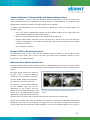
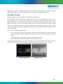
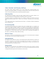
Nextiva Edge Device
Parameters
Configuring Video Encoders, Decoders, and
Cameras for Optimal Video System
Performance
VERINT SYSTEMS INC.
April 2008
Table of Contents
Preface ....................................................................................................... 1
Video Encoder Settings.................................................................................. 3
Target Bit Rate ................................................................................................................... 3
Target Frame Rate .............................................................................................................. 3
Image Resolution................................................................................................................ 3
Quantization (Minimum and Maximum Quantizer).................................................................... 4
Compression Mode.............................................................................................................. 5
Input Filter and Noise Reduction Filter ................................................................................... 5
Rate Control Mode .............................................................................................................. 6
Multiplying Factor for Storage ............................................................................................... 6
Maximum Output Rate per Stream (Traffic Shaper).................................................................. 6
Intra Interval ..................................................................................................................... 7
Bandwidth Control .............................................................................................................. 7
Remote IP Address ............................................................................................................. 7
UDP Data Port .................................................................................................................... 7
Initial Streaming and Current Streaming States ...................................................................... 8
Transport Protocol .............................................................................................................. 8
Energy Vector (EV) Transmission Rate ................................................................................... 8
Web Multicast IP Address and Port ........................................................................................ 8
Target VSIP GUID ............................................................................................................... 8
Video Input Settings ..................................................................................... 9
Video Standard................................................................................................................... 9
Horizontal Position .............................................................................................................. 9
Vertical Position.................................................................................................................. 9
Frame Format .................................................................................................................... 9
Video Rotation.................................................................................................................... 9
Number of Encoders per Video Input ..................................................................................... 9
Max Video Payload Size ....................................................................................................... 9
Brightness ........................................................................................................................10
Contrast ...........................................................................................................................10
Saturation ........................................................................................................................10
Hue .................................................................................................................................10
Video Sensor Settings ................................................................................. 11
Sensor Type: Interlaced and Progressive Scan .......................................................................11
Sensor Preset....................................................................................................................11
White Balance Bias.............................................................................................................12
Lens Type.........................................................................................................................12
Metering Zone ...................................................................................................................13
Gamma Adjustment (Gamma Mode and Gamma Manual Value) ................................................14
Support NTSC in 50 Hz Environment.....................................................................................14
Maximum Slow Shutter Speed Limit .....................................................................................14
Day/Night Settings.............................................................................................................15
Video Decoder and Display Settings .............................................................. 16
Deblocking Filter................................................................................................................16
De-Interlacing Mode...........................................................................................................16
Wait for I-Frame................................................................................................................16
Delay Adjustment ..............................................................................................................16
Receiver Mode...................................................................................................................16
Unauthorized use, duplication, or modification of this document in whole or in part without the written consent of
Verint Systems Inc. is strictly prohibited.
By providing this document, Verint Systems Inc. is not making any representations regarding the correctness or
completeness of its contents and reserves the right to alter this document at any time without notice.
Features listed in this document are subject to change. Please contact Verint for current product features and
specifications.
All marks referenced herein with the ® or TM symbol are registered trademarks or trademarks of Verint Systems Inc.
or its subsidiaries. All rights reserved. All other marks are trademarks of their respective owners.
© 2008 Verint Systems Inc. All rights reserved worldwide.
VINED020408U
Version 1.0
Preface
This document provides information you can use to get optimal performance from Nextiva video
encoders, decoders, and cameras. While many of the default parameters for Nextiva edge devices are
suitable for most applications, knowing how to fine-tune these settings can help make deployment and
operation of video surveillance solutions faster, easier, and more effective.
For your reference, a table on the next page briefly describes each offering in the Nextiva edge device
portfolio. The remainder of the document is presented in four parts:
•
Video Encoder Settings: Optimize video encoding performance; includes Target Bit Rate and
Bandwidth Control
•
Video Input Settings: Capture clear, high-resolution images; includes Horizontal Position,
Saturation, and Hue
•
Video Sensor Settings: Make the most of Nextiva IP cameras; includes Interlaced vs.
Progressive Scan, White Balance Bias, and Day/Night Settings
•
Video Decoder and Display Settings: Render high-quality video for proactive security
operations; includes Deblocking Filter and Receiver Mode
Verint. The Leader in IP Video.
Verint® Systems Inc. is the worldwide leader in networked video, a “single source” for virtually every
facet of video surveillance operations: from cameras, encoders, and intelligent DVRs to video
management, viewing, and analytic software.
Designed to enhance any video network ― large or small, wired or wireless, mostly analog or mostly
IP, and everywhere in between ― Verint solutions help organizations realize the benefits of IP video
using their legacy video investments. With multi-tiered support programs, expert services, and the
award-winning Nextiva® video portfolio, Verint transforms video into value for our partners and their
customers.
1
Nextiva Intelligent Edge Devices
SINGLE-PORT ENCODERS AND DECODERS
S1900e
Compact, high-resolution encoder with on-board analytics capability
S1950e
Compact, high-resolution encoder for affordable CCTV migration to enterprise IP networks
S1970e
DVD-quality encoder for optimal image quality, with optional Power over Ethernet
S1970e-R
Compact decoder for delivering DVD-quality video to analog monitors, with single, quad, or
guard tour display
MULTI-PORT ENCODERS
S1704e
4-port encoder with 4CIF/30fps video on all 4 ports, optional bi-directional audio channel,
and optional on-board analytics
S1708e
8-port encoder with 4CIF/30fps video on all 8 ports, optional bi-directional audio channel or
12 audio inputs, and optional on-board analytics
S1712e
12-port, high-resolution encoder with optional bi-directional audio channel or 12 audio inputs
S1724e
24-port, high-resolution encoder with optional bi-directional audio channel
WIRELESS EDGE DEVICES
S4100
Video encoder/transmitter and receiver (two units) for point-to-point wireless applications,
delivering MPEG-4 based video up to 4CIF/30fps; options include second video input/output
S4200
Video encoder/transmitter for point-to-point or point-to-multipoint wireless applications, with
SSL-based authentication, 802.11a/g and WPA2 support, dual-stream, MPEG-4 based video
up to 4CIF/30fps, optional connection to second analog camera, and available on-board
analytics
S4300
Wireless access point for aggregating traffic from multiple S4200 devices in point-tomultipoint applications; includes Power over Ethernet
S4300-RP
Wireless repeater for retransmitting signals from Nextiva wireless devices to a wired LAN in
point-to-point or point-to-multipoint applications
S4300-BR
Two units that act as a wireless bridge for transferring video between two LANs or
transmitting video from IP cameras
IP CAMERAS
S2600e
Super wide dynamic range (102dB) IP camera with on-board analytics capability and
software-programmable support for both interlaced and progressive scan video
S2610e
Super wide dynamic range (102dB) IP camera designed for day-to-night use, with on-board
analytics capability and software-programmable support for both interlaced and progressive
scan video
S2700e
IP mini-dome camera for day-to-night use, built to deliver DVD-quality video in a variety of
lighting conditions; features triple axis rotation system for flexible camera
placement/adjustment
S2700e-VR
IP66 vandal-resistant, IP mini-dome camera with waterproof/dustproof housing designed to
deliver DVD-quality video in indoor or outdoor, day-to-night applications; features triple axis
rotation system for flexible camera placement/adjustment and optional extended
temperature support
S2750e
IP mini-dome camera with excellent image quality and a robust feature set at an attractive
price
2
Video Encoder Settings
Target Bit Rate
The Target Bit Rate is the maximum number of bits per second generated by the device. It is
calculated over an average of 5 seconds, so it is possible to see some peaks if you look at the target
over a period of 1 second or less. You should set the Target Bit Rate to fit your storage requirements
and network settings. If the amount of motion is low, the encoder could generate fewer bits than the
target, which could lead to long-term storage under the target. This is why the target is, in fact, a
maximum. For best-quality video, you can set the Target Bit Rate to its maximum value (6,000 Kbits
per second). The encoder will not be exceeding the target if the unit is set in Constant Bit Rate (CBR)
mode. In Constant Frame Rate (CFR) mode, the encoder could exceed the target once it reaches the
Maximum Quantizer. (See Quantization on the next page.)
Target Frame Rate
The Target Frame Rate is the number of frames per second encoded and transferred by the encoder.
This parameter can be set for 1 to 7, 10, 15, or 30 fps in NTSC (1 to 6, 8, 12, or 25 fps in PAL). A
higher frame rate will produce more fluid video, but will require a higher bit rate and more processing
power.
Image Resolution
Image Resolution refers to the level of detail in an image. A higher resolution means a greater number
of pixels and therefore a more detailed image. Each resolution corresponds to a specific number of
pixels (columns X lines) in each image of a video sequence. All CIF-defined formats result in images
with an aspect ratio of 4:3, and these are not square.
3
4CIF is the highest resolution, providing the maximum level of detail and resulting in the crispest,
clearest images. For NTSC and PAL images that come from an interlaced source, the QCIF, CIF, and
2CIF resolutions will use only one of the two fields from a typical video signal, avoiding potential
artifacts that result from interlacing. See the table below for the number of columns and lines for each
resolution.
Resolution
Number of
Columns
Number of Lines
NTSC/PAL
NTSC
PAL
QCIF
176
128
144
CIF
352
240
288
2CIFH
704
240
288
4CIF
704
480
576
All Lines (HD1)
352
480
576
2/3 D1
480
480
576
VGA
640
480
576
Quantization (Minimum and Maximum Quantizer)
Quantization is the process of approximating a continuous range of values. Quantization plays a major
role in data compression, reducing the amount of data needed to represent a signal. Together, the
Minimum and Maximum Quantizers establish the “quality” boundaries of a video codec rate controller.
A low quantizer setting will generate high-quality video, resulting in bigger files. A high quantizer
setting will generate low-quality video, resulting in smaller files. Quantizer values range from 2 to 31.
The Minimum Quantizer establishes the high-quality boundary, while the Maximum Quantizer
establishes the low-quality boundary:
•
A minimum of 2 is recommended for optimum quality. You can increase the minimum if you
want to reduce the required bandwidth and storage when there is no motion. Normally, the
Minimum Quantizer should not be set at more than 6.
•
A maximum of 6 is recommended if high-quality video is a priority. The maximum should be
30 if maintaining frame rate is important.
•
If you want consistent quality, use the same settings for both the Minimum and Maximum
Quantizers.
NOTE: In 95% of the cases, when the encoder does not sustain its Target Frame Rate, it is because
the Maximum Quantizer is not set high enough. Set it higher or, if you do not mind exceeding the
Target Bit Rate, set the rate control mode to CFR.
4
Compression Mode
This setting controls the algorithm that is used to compress the video before sending it over the
network. You can choose among the following compression modes:
•
SM4: This is a proprietary compression standard developed by Verint and based on MPEG-4. It
is as good as MPEG-4 in terms of quality and efficiency, and it is a bit more computing
efficient, so use it if you cannot sustain 30 fps with MPEG-4. SM4 requires a lower bit rate,
while maintaining high-quality video and reducing storage costs.
•
MPEG4 Compliant Simple Profile: This is one of the most widely used compression standards
for surveillance video. Use it if you do not have access to Verint decoder tools or if it is
required. You can also use MPEG-4 Compliant Simple Profile if you need to reduce I-Frame
sizes. MPEG-4 and SM4 are similar, but they do not produce exactly the same artifacts, so you
may want to try both and see if you prefer one over the other.
•
MJPEG: This mode compresses each frame individually, so you will have to set the Target Bit
Rate much higher if you want video quality that is comparable to what you would get with SM4
or MPEG-4. Also, use when required.
Input Filter and Noise Reduction Filter
All video content contains some noise, which makes encoding more time-consuming. Two different
filters help decrease encoding time by reducing the amount of noise in a video signal before encoding
takes place. Reducing noise diminishes the overall packet size of the video, but also reduces the
amount of information available to describe the image. When using filters, it is always a trade-off
between bit rates and video quality.
The Input Filter is a spatial filter applied to the video signal before it is encoded, removing high
frequencies in the image.
•
Set the Input Filter to None for optimum quality in 4CIF, 2CIF, or VGA.
•
Set the Input Filter to Low in CIF, All Lines (HD1), or 2/3 D1.
•
Set the Input Filter to Low or Medium to maintain a lower bit rate.
The Noise Reduction Filter is a second filter applied to the video signal that further reduces noise
before encoding. It is very effective in reducing noise and keeping the bit rate low when there is no
motion, because almost no video degradation is detectable.
•
Set the Noise Reduction Filter to Low for optimum quality and bit rate. By doing this, you can
reduce the amount of storage used by about 30%.
•
Set the Noise Reduction Filter to None if you have difficulty achieving 30 fps with a single-port
encoder.
NOTE: The Noise Reduction Filter is available by default on the Nextiva S2600-AS and S2610-AS. It is
available on the non-AS models as well, but only if the second encoder is disabled. The number of
encoders per video input in the CLI menu must be changed from the default setting of 2 to 1. After
the new setting is saved, the Noise Reduction Filter will be available.
5
Rate Control Mode
The Rate Control Mode helps determine the video quality produced by the encoder. The Verint Rate
Control Mode, along with the Target Bit Rate, Target Frame Rate, and Minimum and Maximum
Quantizers provide maximum flexibility in configuring Nextiva encoders.
•
The default value, which is most frequently used, is CBR. In this mode, the encoder will do
everything to keep the bit rate equal or under the target. To do that, it will adjust the
quantizer level within the minimum and maximum ranges that have been set. Once the
Maximum Quantizer (minimum quality) level has been reached, the encoder will reduce video
frame rate.
•
If you want to maintain frame rate, no matter what adjustments to bit rate might be
necessary, set the Rate Control Mode to CFR. The encoder will not increase bit rate over the
target until the Maximum Quantizer level has been reached.
•
If you want a true variable bit rate mode, wherein you set the video quality and the bit rate
can vary, you must set the Rate Control Mode to CFR and set the Minimum and Maximum
Quantizers to the same value.
•
The Constant Storage Rate (CSR) mode (formerly called the Constant Nextiva Rate, or CNR)
works much like the CBR mode, with one difference. With CSR, if the bit rate is lower than the
target for a certain period of time, the bit rate can then be raised above the target value. The
CSR mode is useful in cases where there is no movement for long periods of time (requiring a
very low bit rate), then a lot of fast movement (requiring a high bit rate). This mode must be
used with Nextiva enterprise video management software to make optimal use of storage
capacity.
•
The Advanced Constant Bit Rate (ACBR) mode is similar to CBR in that it maintains the target
bit rate, but it is more precise. As a result, frame rate may decrease and video quality may be
compromised. This mode is preferred for high-frame-rate contexts where it is desirable to
maintain the bit rate.
Multiplying Factor for Storage
If the Rate Control Mode is set to CSR (see above), this parameter specifies the amount by which the
bit rate can exceed the target. The value is expressed as a percentage of the Target Bit Rate. For
example, if the Target Bit Rate is set to 4,000, and the Multiplying Factor for Storage is set to 125, the
actual bit rate, over a certain period of time, could go as high as 5,000 (125% of 4,000).
Maximum Output Rate per Stream (Traffic Shaper)
This setting, under the Test and Debug Menu, should generally not be modified. But if your network
equipment does not support data rate peaks, which occur when there is no memory in the switches,
routers, etc., you might want to shape the video traffic. The Maximum Output Rate per Stream will
shape the traffic to avoid sending to many packets within a few milliseconds. You can set this value
from 10 to 50,000 Kbits per second. The shaper is not related to the Codec Rate Control (CRC), and
the value should be at least 20% over the Target Bit Rate.
6
Intra Interval
This is the interval, in frames, at which the encoder will send an I-Frame (Key Frame). I-Frames
require significantly more memory than their counterparts — P-Frames — so lowering this value can
increase the bit rate or lower the video quality. On the other hand, I-Frames are necessary to
resynchronize the output video when searching for a specific video event. Generally, a value between
30 and 120 should be appropriate. For some networks, setting this value at 0 will help avoid data rate
peaks.
Bandwidth Control
This option permits you to dynamically modify the encoding bit rate and frame rate in relation to the
number of packets lost between a transmitter and receiver. If set to 1 (enabled), this option will work
only if:
•
The video is transmitted from a Verint transmitter to a Verint receiver.
•
The connection has been established properly with SConfigurator, with the proper GUID and IP
addresses in the configuration.
This option is useful for wired or wireless links that do not always have the same available throughput.
Instead of losing a lot of packets over a long period of time, the transmitter will reduce the bit rate up
to 1/8 of the original and the frame rate up to 1/2. The quality will be affected, but at least the video
will be acceptable.
NOTE: This option is available only in single/dual input edge devices. In single-input edge devices,
when the option (menu) is not present, the default setting is 1, but it can be reset by changing the
Target Bit Rate or target file size.
Remote IP Address
This is the IP address of the device (VRU, PC) to which the encoder is sending a static (non-volatile)
stream. You can set a Multicast IP address if required.
UDP Data Port
This is the port used by the User Datagram Protocol, or UDP. The receiver must tune into this same
port in order to get the stream. In TCP mode, the unit will use the VSIP port.
7
Initial Streaming and Current Streaming States
These two parameters control the static (non-volatile) streaming state of the encoder, both actual and
after boot-up.
•
The Current Streaming State controls whether the encoder is actually encoding and sending
video over the network. The stream controlled by this parameter is always non-volatile.
(Volatile streams cannot be seen or controlled in the CLI.) The Current Streaming State
parameter is never saved in the configuration, so set the Initial Streaming State parameter if
a constant setting is desired.
•
The Initial Streaming State setting determines the value of the Current Streaming State after
boot-up. If this is enabled, the Current Streaming State will be enabled as well, and the unit
will start streaming immediately.
Transport Protocol
This parameter specifies both the Internet protocol that will be used to transmit the video stream over
the network and the video protocol that will be used to decode the stream.
•
For the Internet protocol, you have a choice between TCP and UDP — two well-known and
widely used protocols.
•
For the video protocol, you have a choice between VSIP, a proprietary video and audio
protocol, and RTP, an accepted industry standard.
It is suggested that you set this parameter to RTP/UDP. Use TCP only in setups where UDP is not
accepted or if you have occasional packet loss.
Energy Vector (EV) Transmission Rate
The energy vector represents a measurement of movement in the image. Its value can range from 0
(no movement) to 255 (a lot of movement). The Energy Vector (EV) Transmission Rate is the
frequency, in frames, at which the energy vector is computed and sent over the RTP/UDP stream. A
value of -1 means there is no video signal going to the encoder. This setting is used by video
management software only.
Web Multicast IP Address and Port
These are the Multicast IP address and port that will be used only if the Multicast streaming method is
chosen for live viewing on a Web page. To stream Multicast to one or multiple receivers, you must set
the target IP address to a valid Multicast group.
Target VSIP GUID
Useful for TCP streaming, this is very hard to set manually. It is used by SConfigurator or other
software to create non-volatile video TCP connections.
8
Video Input Settings
Video Standard
This is the video standard of the input video, which can be either NTSC or PAL. Generally, the NTSC
standard is used in North America, and the PAL standard is used in Europe and Asia. This setting will
affect both the video resolution and the frame rate. Modifying the video standard requires a reboot of
the encoder to take effect.
Horizontal Position
Use this setting to apply a horizontal translation to the video. This is useful in removing artifacts from
the camera borders.
Vertical Position
Use this setting to apply a vertical translation to the video. This is useful in removing artifacts from
the camera borders.
Frame Format
This parameter determines how video frames are represented in memory. This can be set to field over
field (default), interlaced, or de-interlaced. Set it to interlaced or de-interlaced if you are streaming
video to a non-Verint MPEG-4 decoder (codec). If you want to get rid of interlacing artifact at the
source, you can set the video to be de-interlaced. If the same image appears twice, one overlapping
the other, the settings on the encoder and decoder do not match, and one setting needs to be
changed.
Video Rotation
This setting is available only with some S2600e camera models. It indicates whether the video must
be rotated 180 degrees because the camera has been installed upside down.
Number of Encoders per Video Input
This sets the number of available video encoders — one or two. Setting this value to 2 allows you to
use two different logical encoders — for example, one for video that will be viewed live (high quality)
and another for video that will be stored (low quality). Be aware, though, that some product options,
such as the Noise Reduction Filter, are available only if the number of encoders is set to 1. If this
number is changed, the unit must be rebooted for the new setting to take effect.
Max Video Payload Size
This parameter controls the maximum packet size that can be sent over the network. It has no impact
on the size of each frame or on the bit rate of the video.
9
Brightness
For a brighter (whiter) signal, increase the Brightness. Decreasing it can help reduce storage
requirements.
Contrast
This setting allows you to increase or decrease image contrast. Increasing it makes whites whiter and
blacks blacker. Decreasing it can help reduce storage requirements.
Saturation
Use this setting to increase or decrease the color intensity of images. Increase it for a wider range of
colors in the image. Decreasing it can help reduce storage requirements.
Hue
This setting is used to adjust the relative amounts of red, green, and blue in images.
10
Video Sensor Settings
Sensor Type: Interlaced and Progressive Scan
There are two ways to read image information from a camera sensor: interlaced scanning and
progressive scanning. Which to select depends on the purpose of the video system and whether the
video will be played back on analog monitors or on computer monitors.
•
Use Interlaced Scan if the video is compressed at 30 fps and will be displayed on an analog
monitor. This will result in fluid video at 60 fields per second.
•
Use Progressive Scan if the video will be viewed on a PC monitor.
Using Progressive Scan for video
that
is
viewed
on
an
analog
monitor will result in movement
that is less fluid. Using Interlaced
Scan for video that is viewed on a
PC monitor will introduce some
artifact in video with motion.
NOTE: This setting is important
only if you are using 480 x 576
lines of resolution (NTSC/PAL):
4CIF, 2/3 D1, All Lines (HD1), or VGA.
Interlaced Scan video (left) appears blurry on a PC monitor, whereas
Progressive Scan video yields a clear, undistorted image (right).
Sensor Preset
To adjust image brightness, first use the appropriate predefined Sensor Preset based on the lighting
conditions in which a camera is being used. These presets are groupings of low-level parameters
relative to the luminosity and level of detail in the image.
Since these presets affect image brightness, they also influence dynamic range. The dynamic range of
a camera determines its ability to operate in variable light conditions and display very bright and dark
areas in one scene without missing important details.
The Sensor Presets:
•
Normal: For interior or exterior scenes with a lot of detail and low contrast. This preset will
offer a medium level of dynamic range and should be appropriate for most environments.
•
Indoor: For scenes with less luminosity and detail than Normal. This preset will offer a low
level of dynamic range, which means that image details will be unclear if a camera is aimed at
a window or in any other high-contrast luminosity condition.
•
Outdoor: For scenes with more luminosity and detail than Normal. This preset will offer a high
level of dynamic range and can be used both indoors and outdoors effectively.
Another available setting is Fluorescent 2, but this is used only with interior tungsten fluorescent
lighting, when the electrical network frequency is 50 Hz and the video standard is NTSC. (Make sure
“Support NTSC in 50 Hz Environment” is set to On.) To activate the Fluorescent 2 setting, you must
11
set the Lens Type to Auto-Iris (DC). (See Lens Type below.) NOTE: This setting will result in a low
level of dynamic range.
White Balance Bias
White Balance allows for the adjustment of the relative amounts of red, green, and blue in an image,
such that neutral colors are reproduced more accurately. White Balance changes the overall mixture of
colors to render colors and whites as true as possible.
To adjust colors based on lighting conditions and compensate for ambient light color, use the White
Balance Bias. The best way to adjust
this setting is to place a white piece of
paper over 25% of the image center
and tweak the White Balance Bias to
reproduce as closely as possible the
color of the paper. Possible values
range
from
-2,000
to
2,000.
A
negative offset adds a blue tint to the
image, whereas a positive value adds
red.
Left: with White Balance in incandescent lighting;
Lens Type
right: without Light Balance
The Lens Type determines how the sensor’s iris is adjusted. The iris of a camera, much like the iris of
the human eye, controls the quantity of light that penetrates the camera. The wider the iris is open,
the more light is allowed to go through and the brighter the image will be. There are two lens types:
•
Auto-Iris: In this mode, the sensor will automatically adjust the iris to produce an ideal level of
light.
•
Manual: In this mode, the user will have to adjust the sensor manually for the desired amount
of light to penetrate the iris.
12
Metering Zone
The Metering Zone adjustment forces the IP camera to use the
brightness level in a specific area of an image to determine the
appropriate exposure. Exposure, defined as the amount of light
the sensor gets, will determine the brightness of captured
video.
If images are too dark, try adjusting the Metering Zone, which
has two settings: Normal, for most lighting conditions, and
Backlight, for when objects are illuminated from the back. For
each, the following settings are available:
•
Safe Area (Averaging): Measures the light evenly from
all areas in the frame and sets the exposure to suit the
Metering Zone: The IP camera uses the
brightness level in a specific area of an image to
determine the appropriate exposure.
average light value.
•
Center Spot (Center Weighted): The meter will use a concentrated region around the center of
the focused image. This type of metering technique works well for close-ups of buildings and
people, but poorly for landscapes and in the vicinity of the light source.
•
Custom (Spot): If not used properly, this setting can result in the metered area being well
exposed while the rest of the frame is either underexposed or overexposed. For example, if
the main subject fills only a relatively small portion of a frame and/or reflects significantly
more or less light than the surrounding area — a black cat on a bright white sheet, for
instance — the average exposure for the whole frame may not be ideal.
The Custom Metering Zone is defined as a set of four coordinates (in pixels, always an even number)
representing a rectangle and using the following format:
Coordinate
Description
Range (in pixels)
X
The x coordinate of the upper right corner
0–704
Y
The y coordinate of the upper right corner
0–524
W
The width of the rectangle
16–720
H
The height of the rectangle
16–540
13
Gamma Adjustment (Gamma Mode and Gamma Manual Value)
Gamma Adjustment is used to code and decode luminosity information in video and controls the
overall brightness and color component ratio of an image. It compensates for the nonlinear tonal
reproduction of intensity and colors of output devices such as monitors.
To adjust overall brightness, you can also introduce a signal gain using the Gamma Mode. The
available modes:
•
Auto: The camera automatically chooses the best gamma setting. If this setting does not
produce optimal brightness, use the Manual mode.
•
Manual: Set the gamma correction in the Gamma Manual Value box.
•
Gamma Manual Value: The value can be set from 25 to 100 and will correct the mid-tone
contrast and brightness of the image: The lower the value, the more brightness and contrast
is added to the image.
•
Off: No gamma correction.
Support NTSC in 50 Hz Environment
This parameter must be set to On when the electrical network frequency is 50 Hz and the video
standard is set to NTSC. Also, if this is the case, the Sensor Preset parameter should be set to
Fluorescent 2. (See Sensor Preset.)
Maximum Slow Shutter Speed Limit
The shutter allows light to pass through the lens for a determined period of time. The shutter speed
will determine the exposure time and therefore the overall amount of light that will be collected by the
sensor.
With high shutter speeds, the exposure
to light is brief — ideal for capturing
movement. In the example to the right,
a higher shutter speed (short exposure)
was used for the picture on the left.
The amount of time required depends
on
the
available
light
and
will
be
determined by the camera, but the
Maximum Slow Shutter Speed can be set
A higher shutter speed (left) is ideal for capturing action or
by the user. The Maximum Slow Shutter
motion.
Speed Limit is equivalent to the maximum
exposure time. The sensor will not increase the exposure time if there is enough light.
Another way to improve the low light capability of a camera is to increase the Maximum Slow Shutter
Speed Limit from 2X to 4X, 8X, or higher. The higher the value, the longer the exposure time allowed
by the shutter and the greater the image luminosity, even if the surrounding lighting is low. But it is
14
important to note that a longer exposure time will introduce visual artifacts to images of moving
objects: Movement may not be captured as clearly, and colors might appear washed out.
Day/Night Settings
Day/Night Settings are only available on the S2610e and S2610e-AS.
The Day/Night function switches the camera between day and night modes according to the
brightness level in a scene. When scene illumination is reduced, the IR-Cut filter used to produce color
images is removed so that the camera can make use of IR light and capture images even in very low
light. In this case, the camera will often switch to black and white (monochrome) mode to avoid
distortions introduced by IR light. The Nextiva S2600e offers automatic detection from day to night
mode and automatic switching to black and white; however, it is possible to capture images in color
even in night mode.
These are the Day/Night Control modes:
•
Auto: The camera switches automatically between both modes. Make sure there is enough
light for good-quality video at night, but that the light is low enough so the camera makes the
switch.
•
Forced Night Mode: The camera remains in night mode all the time.
•
Forced Day Mode: The camera remains in day mode all the time.
The Day/Night Gain Boost will increase the video gain by 6 dB when entering night mode to increase
contrast. It will boost existing video signals, but also amplify the internal noise, so use carefully.
Without gain boost
With gain boost
15
Video Decoder and Display Settings
This section outlines settings available on the video receiving side, including decoding, postprocessing, and rendering (display). The settings for streaming states are the same as they are for the
encoder. (See Initial Streaming and Current Streaming States on page 8.)
Deblocking Filter
The deblocking filter attempts to reduce the blocky artifacts present at the edge of blocks (8 x 8
pixels) and created by the DCT/Quantization compression process in the encoder.
On a Nextiva S1970e-R, the deblocking filter can be enabled or disabled, but internally, the level of
deblocking dynamically adjusts itself in relation to the resolution, compression ratio, and decoding
time.
For the SDK decoder library or Microsoft Direct Show filters, it is possible to adjust the Deblocking
Filter to a different level.
De-Interlacing Mode
De-Interlacing Mode determines how interlaced video will be managed before it is rendered. The
setting can be enabled or disabled. Typically, if it is enabled, the unit will apply a de-interlacing filter
prior to rendering the frame. However, with an S1970e-R, if De-Interlacing Mode is enabled and the
incoming video is compressed at 30 or 25 fps, it will not be de-interlaced. In such cases, the video will
be displayed as is. If at some point video is sent at 15 fps or lower, de-interlacing will be applied. For
this reason, it is preferable to always enable this setting.
Wait for I-Frame
This means an I-Frame will be decoded before any frame from a new IP video stream is displayed.
This will prevent you from seeing incomplete video frames.
Delay Adjustment
This setting is used to adjust the number of extra buffered frames allowed between the decoder and
the renderer. The lower it is, the less delay in the complete setup. The higher it is, the smaller are the
chances for a skipped frame effect created by the rendering process. Currently, on an S1970e-R, the
Delay Adjustment can be set between 0 and 2.
Receiver Mode
This applies only to the S1970e-R, and it establishes the way the receiver works, whether in [0]=Solo
(Single View), [1]=Quad View, or [2]=Guard Tour. The unit needs to be rebooted whenever this mode
is changed from Solo to Quad or Solo to Guard Tour, and vice versa.
16