1
Owner's Manual
£RRFfSMR#
19.5HP
ELECTRIC START
42" MOWER
6 SPEED TRANSAXLE
LAW
TRACTOR
Model No.
917.2708t3
• Safety
• Assembly
° Operation
o Maintenance
• Repair Parts
CAUTION:
For answers to your questions
Read and follow all Safety
Rules and Instructions before
operating this equipment.
about this product, CaEI:
1-800-659-5917
Sears Craftsman Help Line
5 am - 5 pro, Mon- Sat
Sears, Roebuck and Co., Hoffman Estates, II 60179
Visit
our Craftsman
website:wwwsearscom/craftsman
Warranty........................................................
2
Maintenance..................................................
17
Safety Rules .............................................
2
Serviceand Adjustments.....................
21
Product Specifications..............................
5
Storage............................................................
27
Assembly...................................................
8
Troubleshooting..........................................
28
Operation.......................................................
11
Repair Parts..................................................
32
MaintenanceSchedule......................17
PartsOrdering.....................Back Cover
LIMITEDTWOYEARWARRANTYONCRAFTSMANRIDINGEQUIPMENT
Fortwo (2) years fromthe date of purchase,if this CraftsmanRidingEquipmentis
maintained,lubricatedand tuned up accordingto the instructionsin the owner's
manual,Searswilt repairor replace,free of charge,any partsfoundto be defectivein
materialor workmanship.
This Warrantydoes not cover:
• Expendableitems which becomeworn during normaluse, such as blades,spark
plugs,air cleaners,belts, etc.
• Tire replacementor repair causedby puncturesfrom outsideobjects,such as nails,
thorns,stumps,or glass.
- Repairsnecessarybecauseof operator abuse,negligence,improperstorage or
accidentor the failure to maintainthe equipmentaccordingto the instructions
containedin the owner's manual.
• Ridingequipmentused for commercialor rentalpurposes_
LIMITED90 DAYWARRANTYON BATTERY
Forninety (90)days fromdate of purchase,if any batteryincludedwith this riding
equipmentprovesdefectivein materialor workmanshipand our testingdeterminesthe
batterywill not hold a charge,Sears will replacethe batteryat no charge.In-home
warrant,]serviceon your Craftsmanridingequipmentis availableat no chargefor 30
daysfrom the date of purchase.Pleasecontactyour nearestservicecenter.After 30
daysfrom the date of purchase,warrantyserviceis availableby takingyour Craftsman
ridingequipmentto your nearestSearsServiceCenter:(In-homewarrantyservicewill
still be availableafter 30 daysfrom the date of purchasebut a standardtrip chargewill
apply)..This warrantyappliesonlywhilethis productis in the UnitedStates.This
Warrantygivesyou specificlegal rights,and you may alsohave other rightswhich may
vary fromstateto state.
SEARS,ROEBUCKANDCO..,D/817WA, HOFFMANESTATES,IL 60179
IMPORTANT:This cuttingmachineis
capableof amputatinghands and feet
and throwingobjects Failureto observe
the followingsafety instructionscould
result in seriousinjuryor death.
GENERA[.
• Clear the area of objects such as
rocks, toys, wire, etc., which could be
picked up and thrown by the blade..
• Be sure the area is clear of other
people before mowing. Stop machine
if anyone enters the area..
• Never carry passengers.
• Do not mow in reverse unless abso-
OPERATION
, Read, understand, and follow all
instructions in the manual and on the
machine before starting.
• Only allow responsible
adults, who are
familiar with the instructions,
to
operate the machine.
2
lutely necessary. Always look down
and behind before and while backing.
• Be aware of the mower discharge
direction and do not point it at anyone°
Do not operate the mower without
either the entire grass catcher or the
guard in place..
, Slowdown beforeturning.
• Never leave a runningmachine
unattended.Alwaysturn off blades,set
parkingbrake,stop engine, and
blades and proceed
down the slope.,
DO NOT:
suddenly turn over if a wheel is over
the edge of a cliff or ditch, or if an edge
caves in.
drugs..
• Watch for traffic when operating near
or crossing roadways..
• Use extra care when loading or
unloading the machine into a trailer or
truck.
• Do not
traction
• Do not
putting
• Do not
slopes.
• Data indicates that operators, age 60
years and above, are involved in a
large percentage
of riding mowerrelated injuries. These operators
should evaluate their ability to operate
the riding mower safely enough to
protect themselves and others from
serious injury°
CHILDREN
machine and the mowing activity. Never
assume that children will remain where
you last saw them.
• Keep children out of the mowing area
and under the watchful care of another
Slopes are a major factor related to lossof-control and tipover accidents, which
can result in severe injury or death. All
slopes require extra caution. If you
cannot back up the slope or if you feel
uneasy on it, do not mow it.
DO:
responsible
aduIL
, Be alert and turn machine
children enter the area..
off if
• Before and when backing, look behind
and down for small children.
o Never carry children° They may fall off
and be seriously injured or interfere
with safe machine operation.
• Never allow children to operate the
machine.
• Mow up and down slopes, not across.
• Remove obstacles such as rocks, tree
limbs, etc
• Watch for holes, ruts, or bumps°
Uneven terrain could overturn the
, Use extra care when approaching
blind corners, shrubs, trees, or other
objects that may obscure vision.
Tall grass can hide ob-
SERVICE
• Use slow speed. Choose a low gear
so that you will not have to stop or shift
while on the slope.
• Follow the manufacturer's
recommendations for wheel weights or counterweights to improve stability.
• Use extra care with grass catchers or
other attachments,
These can change
the stability of the machine.
° Keep all movement on the slopes slow
and gradual.. Do not make sudden
changes in speed or direction.,
• Avoid starting or stopping on a slope. If
tires lose traction, disengage the
mow on wet grass. Reduced
could cause sliding..
try to stabilize the machine by
your foot on the ground_
use grass catcher on steep
Tragic accidents can occur if the operator
is not alert to the presence of children_
Children are often attracted to the
OPERATION
machine.
stacles,
straight
• Do not turn on slopes unless necessary, and then, turn slowly and
gradually downhill, if possible.
• Do not mow near drop-offs, ditches, or
embankments,
The mower could
remove keys before dismounting
• Stop engine before removing grass
catcher or unclogging chute.
• Mow only in daylight or good artificial
light°
• Do not operate the machine white
under the influence of alcohol or
SLOPE
slowly
, Use
and
and
,
,
•
•
extra care in handling gasoline
other fuels. They are flammable
vapors are explosive.
Use only an approved container..
Never remove gas cap or add fuel
with the engine running_ Allow engine to cool before refueling. Do
not smoke.
Never refuel the machine indoors°
Never store the machine or fuel
container inside where there is an
open flame,
er.
3
such as a water heat-
, Neverrun a machineinsidea closed
area.
• Keep nuts and bolts, especiallyblade
attachmentbolts, tight and keep
equipmentin good condition°
• Nevertamperwith safetydevices.
Check their proper operationregularly°
• Keepmachinefree of grass, leaves,or
other debris build-up,Clean oil or fuel
spillage_Allow machineto cool before
storing
• Stop and inspectthe equipmentif you
strikean object..Repair,if necessary,
before restarting.
. Nevermake adjustmentsor repairs
with the enginerunning.
• Grasscatchercomponentsare subject
to wear, damage,and deterioration,
which could exposemoving parts or
allow objectsto be thrown.Frequently
check componentsand replacewith
manufacturer'srecommendedpads,
when necessary.
• Mowerbladesare sharpand can cut.
Wrap the bl&de(s)or wear gloves,and
use extra caution when servicing
them°
• Checkbrake operationfrequently°
Adjust and serviceas required,,
• Be sure the areais clear of other
peoplebefore mowing.Stop machine
if anyoneentersthe area.
• Nevercarry passengers.
• Do not mow in reverseunless absolutelynecessary°Always look down
and behind beforeand while backing°
• Nevercarry children..They mayfall off
and be seriouslyinjuredor interfere
with safe machineoperation..
, Keepchildrenout of the mowingarea
and under the watchful care of another
. Before and when backing, look behind
and down for small children,
responsible
adufL
• Be alert and turn machine
children enter the area,
• Mow up and down slopes (15 ° Max),
not across.
• Remove obstacles such as rocks, tree
limbs, etco
• Watch for holes, ruts, or bumps. Uneven terrain could overturn the machine, Tall grass can hide obstacles°
. Use slow speed Choose a low gear so
that you will not have to stop or shift
while on the slope.
• Avoid starting or stopping on a slope. If
tires lose traction, disengage the
blades and proceed slowly straight
down the slope.
• Do not turn on slopes unless necessary, and then, turn slowly and gradually downhill, if possible.
off if
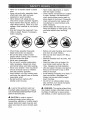
Look for this symbol to point out
important safety precautions.
It means
CAUTtON!!t BECOMEAWARE!!!
YOUR
SAFETY IS INVOLVED,.
CAUTION:
WARNING:
The engine exhaust from
this product contains chemicals known to
the State of California to cause cancer,
birth defects, or other reproductive
harm_
In order to prevent
accidental starting when setting up,
transporting,
adjusting or making repairs
always disconnect spark plug wire and
place wire where it cannot contact spark
plug_
4
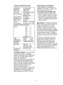
PRODUCT
MAINTENANCE
SPECIFICATIONS
A Sears Maintenance
Agreement
is
available on this product,. Contact your
nearest Sears store for details
GASOLINE
CAPACITY
AND TYPE:
3°5 GALLONS
UNLEADED
REGULAR
OIL TYPE
'API-SFISG/SH):
SAE 30(ABOVE
SAE 5W-30
(BELOW 32°F)
OIL CAPACITY:
3,5 PINTS
SPARK PLUG:
CHAMPION
'GAP: ,030")
RC 12YC
VALVE
INTAKE:
CLEARANCE:
EXHAUST:,004"-.006"
GROUND
CUSTOMER
32°F
rules_
maintaintractor°
"Mainteof this
,004"-,006"
1ST
1_,2
2ND
1,5
3RD
2,.3
4TH
3.5
5TH
4.8
6TH
REVERSE:
5.4
1.5
TIRE
PRESSURE:
FRONT:
REAR:
14 PSI
10 PSI
CHARGING
SYSTEM:
t6AMPS @ 3600RPM
BATTERY:
AMP/HR:
30
MfN, CCA:
240
CASE SIZE:U 1R
BLADE BOLT
TORQUE:
27-35 FT_ LBS
CONGRATULATIONS
of a Craftsman Tractor.,
RESPONSIBILITIES
• Read and observe the safety
• Follow a regular schedule in
ing, caring for and using your
• Follow the instructions
under
nance" and "Storage" sections
owner's manual,
,_ WARNING:
This tractor is equipped
with an internal combustion
engine and
should not be used on or near any
unimproved
forest-covered,
brushcovered or grass-covered
land unless
the engine's exhaust system is equipped
with a spark arrester meeting applicable
local or state laws (if any)_ tf a spark
arrester is used, it should be maintained
in effective working order by the operator.
In the state of California the above is
SPEED FORWARD:
(MPH):
AGREEMENT
required by law (Section 4442 of the
California
Public Resources
Code)..
Other states may have similar laws.
Federal laws apply on federal lands. A
spark arrester for the muffler is available
through your nearest Sears Authorized
Service Center/Department
(See
REPAIR PARTS section of this manual)°
on your purchase
It has been
designed,
engineered
and manufactured
to give you the best possible dependability and performance..
Should you experience
any problem you
cannot easily remedy, please contact
your nearest Sears Authorized
Service
Center_ We have competent, well-trained
technicians
and the proper tools to
service or repair this tractor,
Please read and retain this manual. The
instructions will enable you to assemble
and maintain your tractor properly_
Always observe the "SAFETY RULES".
5
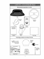
Parts Bag contents
shown
full size
, ,ill
i
1,,, = =
i,,i,
(1) Hex Bolt
3/8-16 x 1
/
_
(1) Lockwasher
Locknut
3f8
5/16-18
(1) Hex Bolt
5/16-18 x 1-1/4
(1) Large Fiat Washer
(1) Shoulder
Bolt 5/16-18
(1) Knob
(I) Washer
17/32 x 1-3/16 x 12 Gauge
(2) Screws
#10 x 5/8
(2) Lock Washers
(2) Weld
(2) Washers
3/16 x 3/4x
16 Gauge
6
Nuts
#10
_
#10
Parts packed separately
in carton
Seat
Mulcher
Plate
Steering
Wheel
Video
Cassette
t
Steering
Boot
Manual
Parts Bag contents
,
I
Parts Bag
not shown full size
Steering
Wheel
Insert
_k
Assemblies
(2) Keys
5
=
Slope Sheet
Steering Wheel
Adapter
7
0
Steering
Extension
Shaft
Your new tractor has been assembled at the factory with exception of those parts left
unassembled
for shipping purposes. To ensure safe and proper operation of your
tractor all parts and hardware you assemble must be tightened securely_ Use the
correct tools as necessary to insure proper tightness., Review the video cassette before
you begin.
TOOLS
REQUIRED
FORASSEIVlBLY
A socket wrench set will make assembly
easier,. Standard wrench sizes you need
are listed below,.
(1) 9/16"wrench
(2) 1/2" wrench
(1) 3/4" socket with
drive ratchet
(1) Tire
pressure
(1)
(1)
Utility knife
Phillips
screwdriver
gauge
Extension
When right or left hand is mentioned in
this manual, it means, from your point of
view, when you are in the operating
position (seated behind the steering
wheel)..
__
Shaft ...._
5t16
Adapter
Locknut
___
/ 5/16 Hex Bolt
_
TO REMOVE "TRACTOR FROM
CARTON
UNPACK
CARTON
Shaft
• Remove all accessible
loose parts and
parts boxes from shipping carton,,
• Cut, from top to bottom, along lines on
ali four corners of shipping carton, and
lay panels flaL
• Check for any additional loose parts or
boxes and remove.
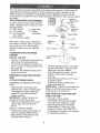
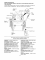
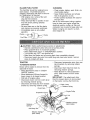
BEFORE
SKID
ROLLING
ATTACH
TRACTOR
STEERING
ASSEMBLE
BOOT
• Position steering wheel so cross bars
are horizontal (left to right) and slide
inside boot and onto adapter
• Assemble large flat washer 318 lock
washer, 318 hex bolt and tighten
securely.
• Snap steering wheel insert into center
of steering wheel
• Remove protective materials from
tractor hood and grill
IMPORTANT:
Check for and remove any
staples in skid that may puncture tires
where tractor is to roll off skid
OFF
WHEEL
EXTENSION
SHAFT AND
• Slide extension shaft onto lower
steering shaft. Align mounting holes
in extension and lower shafts and
install 5/16 hex bolt and IocknuL
Tighten securely°
IMPORTANT:
Tighten bolt and nut
securely to 18-22 ft. Ibso torque.
. Place tabs of steering boot over tab
slots in dash and push down to
secure°
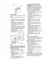
INSTALL
• Position
STEERING
HOWTO
CHECK
SET UPYOUR
TRACTOR
BATTERY
• Lift hood to raised position°
• If this battery is put into service after
month and year indicated on label
(label located between terminals)
charge battery for minimum of one
hour at 6-10 amps. (See "BATTERY"
in Maintenance
section of this manual
for charging instructions),
WHEEL
front wheels
, t'. , ,, ,--_--_/ j_._c.ma
7 ,_'h
r ....
' , Slots
of the tractor so
they are pointing straight forward,
° Slide steering wheel adapter onto
steering shaft extension_
8
.._+,;+:::_, ._"
TO DRIVE
._ 7_ _ .
INSTALL
Adjust
knob.
clear of other people and objects.
• Be sure all the above assembly steps
have been completed.
• Check engine oil level and fill fuel tank
with gasoline.
• Sit on seat in operating position,
depress clutchlbrake
pedal and set the
parking brake,.
• Place gear shift lever in neutral (N)
position,
• Press lift lever plunger and raise
attachment lift lever to its highest
position.
: Start the engine, After engine has
started, move throttle control to idle
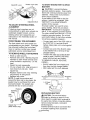
SEAT
tightening
adjustment
• Remove cardboard
packing on seat
pan.
• Place seat on seat pan and assemble
shoulder bolt. Tighten shoulder bolt
securely.
• Assemble adjustment
knob and flat
washer loosely,. Do not tighten,
• Lower seat into operating position
and sit on seat,.
position.
• Depress clutchfbrake
pedal into full
"BRAKE" position and hold, Move
gearshift lever to 1st gear_
• Slowly release clutchlbrake
pedal and
slowly drive tractor off skid,.
, Apply brake to stop tractor, set parking
brake and place gearshift lever in
neutral position.
• Turn ignition key to "OFF" position.
Continue with the instructions
that
foltow_
• Slide seat until a comfortable
position
is reached which allows you to press
clutchlbrake
pedal all the way down..
• Get off seat without moving its
adjusted
position.
• Raise seat and tighten adjustment
knob securely..
Shoulder
in
the Operation section of this manual. Be
sure tractor is in a well-ventilated
area.
Be sure the area in front of tractor is
i
seat before
OFF SKID
WARNING:
Before starting, read,
understand
and follow all instructions
Label
i
TRACTOR
Seat Pan _'_"_---,-">_
Bolt
/I
..... \t
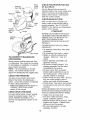
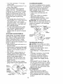
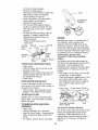
INSTALL
MULCHER
PLATE
• Install two latch hooks to mulcher plate
using screw, washer, lock washer, and
weld nut as shown.
NOTE: Pre-assemble
weld nut to latch
"'''"
hook by inserting weld nut from the top
with hook pointing down,
• Tighten hardware securely.
• Raise and hold deflector shield in
Flat Washer
Adjustment
Knob
TO ROLL
Operation
function
TRACTOR
OFF SKID
section
for location
upright position,
. Place front of mulcher plate over front
of mower deck opening and slide into
place, as shown,
• Hook front latch into hole on front of
mower deck.
• Hook rear latch into hole on back of
mower deck.
,_ CAUTION:
Do not remove discharge
guard from mower, Raise and hold guard
when attaching mulcher plate and allow
it to rest on plate while in operation
(See
and
of controls)
• Press lift lever plunger and raise
attachment lift lever to its highest
position.
- Release parking brake by depressing
clutch/brake
pedal,.
• Place gearshift lever in neutral (N)
position.
• Roll tractor forward off skid.
- Remove banding holding
guard up against tractor,
discharge
9
Hook
Points
Down
Weld Nut
From The To
Weld Nut
Lock
Washer
CHECK
FOR
PROPER
OF ALL
BELTS
POSITION
See the figures that are shown for
replacing motion and mower blade drive
belts in the Service and Adjustments
section of this manual,. Verify that the
belts are routed correctly_
Latch
Hook
Latch
CHECK
Washer
After you learn how to operate your
tractor, check to see that the brake is
properly adjusted° See "TO ADJUST
BRAKE" in the Service and Adjustments
section of this manual,
_ck
Nut
i Washer
asher
Mulcher
Plate
BRAKE
JCHECKLIST
,_,jScrew
BEFORE
YOU OPERATE
PLEASE REVIEW
CHECKLIST:
TO CONVERT TO BAGGING
DISCHARGING
OR
Simply remove mulcher plate and store
in a safe place_ Your mower is now ready
for discharging
or installation of optional
grass catcher accessory,
NOTE: it is not necessary to change
blades. The mulcher blades are defor discharging
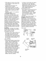
TIRE
and bagging
also.
best cutting results. (Tires must be
properly inflated for leveling).,
¢" Check mower and drive belts. Be sure
they are routed properly around
pulleys and inside all belt keepers.
,/Check
wiring, See that all connections
are still secure and wires are properly
clamped
WHILE LEARNING HOW TO USE YOUR
TRACTOR, PAY EXTRAATTENTION
TO
THE FOLLOWING
IMPORTANT ITEMS:
PRESSURE
The tires on your tractor were overinflated at the factory for shipping purposes_ Correct tire pressure is important
for best cutting performance.
. Reduce tire pressure to PSI shown in
"PRODUCT SPECIFICATIONS"
section of this manual
CHECK
DECK
LEVELNESS
For best cutting results, mower housing
should be properly leveled. See "TO
LEVEL MOWER HOUSING" in the
Service and Adjustments
manual_
section
THE FOLLOWING
V"All assembly instructions
have been
completed.
V' No remaining loose parts in carton.
,/Battery
is properly prepared and
charged.
(Minimum 1 hour at 6
amps).
•/Seat
is adjusted comfortably and
tightened
securely.
•/ All tires are properly inflated° (For
shipping purposes, the tires were
overinflated
at the factory).
V" Be sure mower deck is properly
leveled side-to-sidelfront-to-rear
for
Latch Hooks
CHECK
AND ENJOY
YOUR NEW TRACTOR, WE WISH TO
ASSURE THAT YOU RECEIVE THE
BEST PERFORMANCE
AND
SATISFACTION
FROM THIS QUALITY
PRODUCT,
Deflecto
Shield
signed
SYSTEM
V' Engine oil is at proper level.
V' Fuel tank is filled with fresh, clean,
regular unleaded gasoline.
¢" Become familiar with all controls ° their
of this
location and function.
Operate them
before you start the engine..
./Be sure brake system is in safe
operating
condition°
10
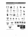
These symbolsmay appearon your tractoror in literaturesuppliedwith the product,
Learn and understandtheir meaning,
M
BATTERY
CAUTION OR
WARNING
REVERSE
FORWARD
LIGHTS ON
ENGINE ON
FUEL
ATTACHMENT
CLUTCH ENGAGED
IGNITION
FAST
ENGINE OFF
OIL PRESSURE
CHOKE
MOWER HEIGHT
REVERSE
ATTACHMENT
CLUTCH DISENGAGED
OVER TEMP
LIGHT
PARKtNG BRAKE
LOCKED
NEUTRAL
HIGH
LOW
KEEP AREA CLEAR
SLOW
l
UNLOCKED
MOWER LIFT
PARKING BRAKE
SLOPE HAZARDS
(SEE SAFETY RULES SECTION
FREE WHEEL
DANGER,
KEEP HANDS AND FEET AWAY
(Aulomatic
tl
Models only)
KNOW
YOUR TRACTOR
READ THIS OWNER'S
YOUR TRACTOR
MANUAL
AND SAFETY
RULES
BEFORE
OPERATING
Compare the illustrations with your tractor to familiarize yourself with the locations
various controls and adjustments.
Save this manual for future reference_
of
ht Switch
Lever
Plunger
Choke Contro
t
Throttle
O
Attachment
Lift Lever
Clutch/
Brake Pedal
g Brake Lever
Gearshift Lever
Height
Adjustment
Knob
Our tractors conform to the safety standards of the
American National Standards Institute.
AMMETER
- Indicates charging (+) or
discharging
(-) of battery.
ATTACHMENT
CLUTCH LEVER .. Used
GEARSHIFT
LEVER - Selects the speed
and direction of tractor.
HEIGHT ADJUSTMENT
KNOB - Used to
to engage the mower blades, or other
attachments
mounted to your tractor.
ATTACHMENT
LIFT LEVER - Used to
adjust the mower cutting height°
IGNITION SWITCH - Used for starting
and stopping the engine,
LIFT LEVER PLUNGER - Used to
release attachment lift lever when
changing its position.
LIGHT SWITCH - Turns the headlights on
and off
PARKING BRAKE LEVER - Locks
clutch!brake
pedal into the brake
position.
THROTTLE
CONTROL - Used to control
raise, lower, and adjust the mower deck
or other attachments
mounted to your
tractor
CHOKE CONTROL
- Used when starting
a cold engine.
CLUTCH/BRAKE
PEDAL - Used for
declutching
and braking
starting the engine,
the tractor
and
engine
12
speed.
The operationof anytractorcan resultin foreignobjectsthrowninto the
eyes,which can resultin severeeye damage. Alwayswear'safety
glassesor eye shieldswhile operatingyour tractoror performingany
adjustmentsor repairs° We recommenda wide visionsafety maskover'
spectaclesor standardsafetyglasses.
HOW TO USE YOUR TRACTOR
TO SET PARKING
• Never use choke to stop engine°
IMPORTANT:
Leaving the ignition
switch in any position other than "OFF"
will cause the battery to be discharged,
(dead).
NOTE: Under certain conditions when
BRAKE
Your tractor is equipped with an operator
presence sensing
switch.. When engine
ts running, any attempt by the operator to
leave the seat without first setting the
parking brake will shut off the engine.
• Depress clutch/brake
pedal into full
"BRAKE" position and hold.,
• Place parking brake lever in "ENGAGED" position and release pressure from clutch/brake
pedal.. Pedal
should remain in "BRAKE" position
Make sure parking brake will hold
tractor secure°
Attachment Clutch Lever
Choke
"En
ed" Position
Control ---..
tractor is standing idle with the engine
running, hot engine exhaust gases may
cause "browning" of grass. To eliminate
this possibility, always stop engine when
stopping tractor on grass areas_
_, CAUTION:
Always stop tractor
completely, as described above, before
leaving the operator's position; to empty
grass catcher, etc_
TO USE THROTTLE
Always operate engine at full throttle.
• Operating engine at less than full
throttle reduces the battery charging
rate.,
"Disengaged"
Position
Throttle
Parking
Brake
"Engaged"
Position
Clutch/
Brake_
. Full throttle offers the best bagging
and mower performance.
TO USE CHOKE
"Disengaged
Position
Height
Position
Adjustment
Knob
STOPPING
BLADES
BACKWARD
-
The direction and speed of movement
is
controlled by the gearshift
lever.
• Start tractor with clutchtbrake
pedal
depressed
and gearshift lever in
neutral (N) position,
• Move gearshift lever to desired
position.
• Slowly release clutchtbrake
pedal to
start movement.
. To stop mower blades,move
attachment clutch lever to "DISENGAGED"
position.
GROUND DRIVE
-
• To stop ground drive, depress clutch/
brake pedal into full "BRAKE" position.
• Move gearshift
lever to neutral (N)
position.
ENGINE • Move throttle control to slow position..
NOTE: Failure to move throttle control to
slow position and allowing engine to idle
before stopping may cause engine to
"backfire".
• Turn ignition key to "OFF" position and
remove key. Always remove key when
leaving tractor to prevent unauthorized
use,
CONTROL
Use choke control whenever you are
starting a cold engine., Do not use to start
a warm engine.
• To engage choke control, pull knob
out° Slowly push knob in to disengaged
TO MOVE FORWARD
AND
rshift
Lever
MOWER
CONTROL
IMPORTANT:
Bring tractor to a complete
stop before shifting or changing gears.
Failure to do so will shorten the useful
life of your' transaxle,
TO ADJUST MOWER CUTTING
HEIGHT
13
The cutting height is controlled by
turning the height adjustment
knob in
desired direction..
• Turn knobclockwise( f"-,I
TO OPERATE
) to raise
cutting height..
, Turn knob counterclockwise
()_'_) to
lower cutting height.
The cutting height range is approximately 1-I12" to 4".. The heights are
measured from the ground to the blade
tip with the engine not running. These
heights are approximate
and may vary
depending
upon soil conditions,
height
of grass and types of grass being
mowed..
Your tractor is equipped with an operator
presence sensing switch
Any attempt by
the operator to leave the seat with the
engine running and the attachment
clutch engaged will shut off the engine°
• Select desired height of cut
• Lower mower with attachment
lift
control
. Start mower blades by engaging
attachment clutch control
• TO STOP MOWER BLADES - disengage attachment clutch control
,_ CAUTION:
Do not operate the mower
without either the entire grass catcher, on
mowers so equipped, or the discharge
guard in place°
• The average lawn should be cut to
approximately
2-t12 inches during the
cool season and to over 3 inches
during hot months.
For healthier and
better looking lawns, mow often and
after moderate growth.
• For best cutting performance,
grass
over 6 inches in height should be
mowed twice_ Make the first cut
relatively
height.
TO ADJUST
high; the second
MOWER
Attachment Clutch Lever "Engaged"
Position_//_
to desired
/
. !_,_..i_'_:
__
GAUGE
Po,,tior,
"Dtsen_gage___
_._)
TO OPERATE
_
) _
Guard.
ON HILLS
,_ CAUTION:
Do not drive up or down
hills with slopes greater than 15" and do
not drive across any slope
• Choose the slowest speed before
starting up or down hills
. Avoid stopping or changing speed on
hills
• If slowing is necessary, move throttle
control lever to slower position
• If stopping is absolutely necessary,
push clutch/brake
pedal quickly to
brake position and engage parking
brake
• Move gearshift
lever to 1st gear
Be
sure you have allowed room for tractor
to roll slightly as you restart movement
• To restart movement, slowly release
parking brake and clutch/brake
pedal
- Make all turns slowly.
TO TRANSPORT
• Adjust gauge wheels with tractor on a
flat level surface
• Adjust mower to desired cutting height
(See "TO ADJUST MOWER CUTTING
HEIGHT" in the Operation section of
this manual)
• With mower in desired height of cut
position, gauge wheels should be
assembled so they are slightly off the
ground
Install gauge wheel in
appropriate
hole with shoulder bolt,
3/8 washer, and 3/8-16 locknut and
tighten securely
• Repeat for opposite side installing
gauge wheel in same adjustment
hole
318_!6
Locknut_.,
Gauge Wheel
Lever High
WHEELS
Gauge wheels
are properly adjusted
when they are slightly off the ground
when mower is at the desired cutting
height in operating position
Gauge
wheels then keep the deck in proper
position to help prevent scalping in most
terrain conditions
Gauge
Wheel
Mounting
Bracket
3t8
Attachemnt Lift
? Position
• Raise attachment lift to highest
position with attachment
lift control.
• When pushing or towing your tractor,
be sure gearshift lever is in neutral (N)
position.
Shoulder
Bolt
14
, Do not pushor tow tractorat more than
gas can damage the fuel system of an
engine while in storage.
To avoid engine
problems, the fuel system should be
emptied before storage of 30 days or
longer. Drain the gas tank, start the
engine and let it run until the fuel lines
and carburetor are empty. Use fresh fuel
next season,. See Storage Instructions
for additional information.
Never use
engine or carburetor cleaner products in
the fuel tank or permanent damage may
five (5) MPH
NOTE: To protect hood from damage
when transporting
your tractor on a truck
or a trailer, be sure hood is closed and
secured to tractor° Use an appropriate
means of tying hood to tractor (rope,
cord, etc,)..
"TOWING CARTS
ATTACHMENTS
AND
OTHER
occur.
Tow only the attachments
that are
recommended
by and comply with
specifications
of the manufacturer
of your
tractor° Use common sense when towing.
Too heavy of a load, while on a slope, is
dangerous_ Tires can lose traction with
the ground and cause you to lose control
of your tractor.
BEFORE
CHECK
STARTING
ENGINE
THE
_b, CAUTION:
Fill to bottom of gas tank
filler neck. Do not overfill,. Wipe off any
spilled oil or fuel. Do not store, spill or
use gasoline near an open flame..
TO START ENGINE
When starting the engine for the first time
or if the engine has run out of fuel, it will
take extra cranking time to move fuel
from the tank to the engine..
• Sit on seat in operating position,
depress clutch/brake
pedal and set
parking brake,.
• Place gear shift lever in neutral (N)
position.
- Move attachment clutch to "DISENGAGED" position.
• Move throttle control to fast position
• Pull choke control out for a cold
engine start attempL For a warm
engine start attempt the choke control
may not be needed_
NOTE: Before starting, read the warm
and cold starting procedures
below.
• Insert key into ignition and turn key
clockwise to "START" position and
release key as soon as engine starts°
Do not run starter continuously
for
more than fifteen seconds per minute,
If the engine does not start after
several attempts, push choke control
in, wait a few minutes and try again. If
engine still does not start, pull the
choke control out and retry,
WARM WEATHER STARTING (50 ° F and
above)
• When engine starts, slowly push
choke control in until the engine
begins to run smoothly° If the engine
starts to run roughly, pull the choke
control out slightly for a few seconds
and then continue to push the control
in slowly_
• The attachments
and ground drive can
now be used. If the engine does not
accept the load, restart the engine and
allow it to warm up for one minute
using the choke as described
above.
ENIGNE
OIL LEVEL
• The engine in your tractor has been
shipped, from the factory, already filled
with summer weight oi!
• Check engine oil with tractor on level
ground..
• Remove oil fil! cap/dipstick
and wipe
clean, reinsert the dipstick and screw
cap tight, wait for a few seconds,
remove and read oil level,. If necessary, add oil until "FULL" mark on
dipstick is reached.
Do not overfill,.
o For cold weather operation you should
change oil for easier starting (See "OIL
VISCOSITY
CHART" in the Maintenance section of this manual)..
° To change engine oil, see the Maintenance section in this manual.
ADD GASOLINE
• Fill fuel tank. Use fresh, clean, regular
unleaded gasoline with a minimum of
87 octane.
(Use of leaded gasoline
will increase carbon and lead oxide
deposits and reduce valve life).. Do
not mix oil with gasoline
Purchase
fuel in quantities that can be used
within 30 days to assure fuel freshhess.
IMPORTANT:
When operating in
temperatures
below 32°F(0°C),
use
fresh, clean winter grade gasoline to
,_lp insure good cold weather starting,
WARNING:
Experience indicates that
alcohol blended fuels (called gasohol or
using ethanol or methanol) can attract
moisture which leads to separation and
formation of acids during storage.
Acidic
15
COLD WEATHER STARTING (50 ° F and
below)
. When engine starts, slowly push
choke control in until the engine
begins to run smoothly, Continue to
push the choke control in small steps
allowing the engine to accept small
changes in speed and load, until the
choke control is fully ino If the engine
starts to run roughly, pull the choke
control out slightly for a few seconds
and then continue to push the control
in slowly. This may require an engine
warm-up period from several seconds
to several minutes, depending
on the
temperature.
• The attachments
can be used during
the engine warm-up period and may
require the choke control be pulled out
slightly.,
NOTE: If at a high altitude (above 3000
feet) or in cold temperatures
(below 32
F) the carburetor fuel mixture may need
to be adjusted for best engine performance. See "TO ADJUST CARBURETOR" in the Service and Adjustments
section of this manual_
MOWING
• When operating attachments,
select a
ground speed that will suit the terrain
and give best performance
of the
attachment
being used.
f
MULCHING MOWING TIPS
IMPORTANT:
For best performance,
keep mower housing free of built-up
grass and trash, Clean after each use,
• The special mulching blade will recut
the grass clippings many times and
reduce them in size so that as they fall
onto the lawn they will disperse into
the grass and not be noticed. Also, the
mulched grass will biodegrade
quickly
to provide nutrients for the lawno
Always mulch with your highest
engine (blade) speed as this will
provide the best recurring action of the
blades°
• Avoid cutting your lawn when it is wet,,
Wet grass tends to form clumps and
interferes with the mulching action.
The best time to mow your lawn is the
early afternoon,, At this time the grass
has dried and the newly cut area will
not be exposed to the direct sun.
o For best results, adjust the mower
cutting height so that the mower cuts
off only the top one-third of the grass
blades. For extremely heavy mulching,
reduce your width of cut on each pass
and mow slowly.
• Certain types of grass and grass
conditions may require that an area be
mulched a second time to completely
hide the clippings.
When doing a
second cut, mow across or perpendicular to the first cut path.
• Change your cutting pattern from week
to week. Mow north to south one week
then change to east to west the next
week. This will help prevent matting
and graining of the lawn.
TIPS
• Mower should be properly leveled for
best mowing performance.
See "TO
LEVEL MOWER HOUSING" in the
Service and Adjustments
section of
this manual.
• The left hand side of mower should be
used for trimming.
• Drive so that clippings are discharged
onto the area that has been cut° Have
the cut area to the right of the tractor,
This will result in a more even distribution of clippings and more uniform
cutting.
• When mowing large areas, start by
turning to the right so that clippings wilt
discharge away from shrubs, fences,
driveways, etc. After one or two
rounds, mow in the opposite direction
making left hand turns until finished.
• If grass is extremely tall, it should be
mowed twice to reduce load and
possible fire hazard from dried
ctippings,
Make first cut relatively
high; the second to the desired height°
• Do not mow grass when it is wet Wet
grass will plug mower and leave
undesirable
clumps.
Allow grass to
dry before mowing..
• Always operate engine at full throttle
when mowing to assure better mowing
performance
and proper discharge of
material.
Regulate ground speed by
selecting a low enough gear to give
the mower cutting performance
as well
as the quality of cut desired.
r
Max 1t3"
I6
Choc.
_roke
Operation
.CheckTl'eP'essu'e
T
_
V'
:V"
_
o.oo.
o0oro,o.
oooooo
oo.
Interlock
Systems
Lubrication
Chart
Transaxle
Adjust
Blade
Belt(s)
Motlon
Drive
III
IIIII
I
Check
Change
E
N
I
I
LI
Engine
II
Engine
Ciean
Air Screen
V',
I
_
III
.
.
.
if
_'r,
_,_
I
I
II
I L
I
_#'
1_._.3
V #'
_"_
Arrestor
Rop_aoe
Spark
PI"g
i
!_
I
I _i=1
......................................
Replace
Air F#ter Paper Cartridge
Replace
Fuel
_'
Ftfter
I
1
1
i
!
V ...............
_'
_5 - I_ eq#ipped
6 - Net
7 * Tlghlee
DO
w{th
reqidred
The warranty on this tractor does not
cover items that have been subjected to
operator abuse or negligence.
To
receive full value from the warranty,
operator must maintain tractor as
instructed in this manual.
Some adjustments will need to be made
periodically
to properly maintain your
tractor,
All adjustments
in the Service and
Adjustments
section of this manual
should be checked at least once each
season.
adiuelab!e
it equipped
aystem
wtlh
_Front Wheel,-i!
Bearing _V"
* Once a year you should replace the
spark plug, clean or replace air filter,
and check blades and belts for wear_
"--r
r--- _) Spindle
II1_-_ Zerk
,
j-i
/,,.._/I:
l
battery
m_xlmum
CHART
Spindle -r--------_,
Zerk
_-"__
Zerk
mainlenmnce4ree
front axle pivot bolt _o 35 _t.-lbs
not overllghlen
LUBRICATION
RECOMMENDATIONS
_,,_= ==' !
-
- "_Z - - --
{_Front Wheel
Bearing
_L"-_ rk
"r -#
I
'-
__Ge'arshift
_.... -J
Pivots
d) SAE 30 or t0W30 Motor OII
@ General Purpose Grease
(3.)Refer to Maintenance "ENGINE" section
A new spark plug and clean air filter
assure proper air-fue! mixture and
help your engine run better and last
longer.
BEFORE EACH USE
Check engine oil level.
Check brake operation,
Check tire pressure,
Check operator presence and
interlock systems for proper operation.
• Check for loose fasteners.
I
_/'z
Chr_nge mete often when eperal{ng _Jnde_"a heavy load o_"In high ambient temper_l=._res
Service more o_en when operating tn dirty or d*,ls|y cond_,ilan._
If equipped wilh o_l rifler, change ott every 50 hours
Replace blades more at:ten when mowing In sandy soil
GENERAL
..........
V;
Replace
0iiFilter
(ifequipped) I
-
I I I 1 Ii
_#'2
__inspec_ Mui_er/spa,k
1
2
3
4
_
.........................................................
Tension
Oil
Air Filler
.
_'_
Tension
Belt(s)
Oil Level
Ciean
I
.
Cooling
Adjust
I'1111 IIIIIIII
I
_,f
e'or
.................
o Che_, Ba!ter','_L
R CIean Battery and Terminals
Check
I
t,_
R Check for LoOSe Fasteners
' V'
A _S._;p_;_R_ple_e
_Mow_Bi"_e_......................
c
i
IMPORTANT:
Do not oil or grease the
pivot points which have special nylon
bearings,, Viscous lubricants wil! attract
dust and dirt that will shorten the life of
.
.
.
.
17
the self-lubricating
bearings,
If you feet
they must be lubricated, use only a dry,
powdered graphite type lubricant
sparingly,
TRACTOR
• Install new or resharpened
blade with
trailing edge up towards deck as
shown..
Always observe safety rules when
performing
any maintenance..
BRAKE OPERATION
IMPORTANT:
To ensure proper assembly, center hole in blade must align with
star on mandrel assembly.
• Reassemble
hex bolt, lock washer and
flat washer in exact order as shown.
• Tighten bolt securely (27_35 Ft. Lbs_
torque).
IMPORTANT:
Blade bolt is Grade 8 heat
treated.
if tractor requires more than six (6) feet
stopping distance at high speed in
highest gear, then brake must be
a djustedo (See "TO ADJUST BRAKE" in
the Service and Adjustments
section of
this manual),
TIRES
o Maintain proper air pressure in all tires
(See "PRODUCT SPECIFICATIONS"
section of this manual)
• Keep tires free of gasoline, oil, or
insect control chemicals which can
harm rubber,,
Trailing Edge Up
Blade
Hex Bolt
*A Grade 8 heat treated bolt can be identified
by six lines on the bolt head,
TO SHARPEN
Care should be taken to keep the blade
balanced.. An unbalanced
blade will
cause excessive vibration and eventual
damage to mower and engine_
. The blade can be sharpened with a
file or on a grinding wheel. Do not
attempt to sharpen while on the
mower.
the disengaged
position,.
• When the engine is running, any
attempt by the operator to leave the
seat without first setting the parking
brake should shut off the engine.
• When the engine is running and the
attachment
clutch is engaged, any
attempt by the operator to leave the
seat should shut off the engine.
• The attachment clutch should never
For best results
kept sharp.
blades.
BLADE
mower
Replace
BLADE
NOTE: We do not recommend sharpening blade - but if you do, be sure the
blade is balanced°
Be sure operator presence and interlock
systems are working properly., if your
tractor does not function as described,
repair the problem immediately_
• The engine should not start unless the
clutch/brake
pedal is fully depressed
and attachement
clutch control is in
the operator
Center
Hole
Flat Washer..
Lock Washer
• Avoid stumps, stones, deep ruts, sharp
objects and other hazards that may
cause tire damage..
NOTE: To seal tire punctures and
prevent flat tires due to slow leaks, tire
sealant may be purchased from your
local parts dealer.. Tire sealant also
prevents tire dry rot and corrosion.
OPERATOR
PRESENCE SYSTEM
operate unless
seat°
BLADE CARE
Mandrel Assembly
- To check blade balance, you will need
a 5/8" diameter steel bolt, pin, or a
cone balancer.
(When using a cone
balancer, follow the instructions
supplied with balancer 0
NOTE: Do not use a nail for balancing
blade. The lobes of the center hole may
appear to be centered, but are not.
. Slide blade on to an unthreaded
is in the
portion of the steel bolt or pin and hold
the bolt or pin parallel with the ground.
If blade is balanced, it should remain
in a horizonta! position.
If either end of
the blade moves downward,
sharpen
the heavy end until the blade is
balanced.
blades must be
bent or damaged
REMOVAL
• Raise mower to highest position to
allow access to blades..
• Remove hex bolt, lock washer and flat
washer securing blade.
18
NOTE: Although multi-viscosity
oils
(5W30, IOW30 etc.) improve starting in
cold weather, these multi-viscosity
oils
will result in increased oil consumption
when used above 32°R Check your
engine oil level more frequently to avoid
possible engine damage from running
low on oil.
BATTERY
'four tractor has a battery charging
system which is sufficient for normal use,
However, periodic charging of the battery
with an automotive
charger will extend
its life,,
. Keep battery and terminals clean,
. Keep battery bolts tight,
. Keep small vent holes open,
, Recharge at 6-10 amperes for t hour.,
NOTE: The original equipment battery on
your tractor is maintenance free,, Do not
attempt to open or remove caps or
covers. Adding or checking level of
electrolyte is not necessary.
TO CLEAN BATTERY AND TERMINALS
Change the oil after every 50 hours of
operation or at least once a year if the
tractor is not used for 50 hours in one
year.
Check
Corrosion and dirt on the battery and
terminals can cause the battery to "leak"
power_
• Remove terminal guard,
• Disconnect BLACK battery cable first
then RED batteR,' cable and remove
battery from tractor.
• Rinse the battery with plain water and
dry,
° Clean terminals and battery cable
ends with wire brush until bright,,
° Coat terminals with grease or petroleum jelly.,
. Reinstall battery (See "REPLACING
BATTERY" in the SERVICE AND
ADJUSTMENTS
section of this
TO CHANGE
ENGINE
OIL
• Oil will drain more freely when warm,
• Catch oil in a suitable container,
• Remove oil fill cap/dipstick,,
Be careful
not to allow dirt to enter the engine
when changing oilo
• Remove drain plug,,
• After oil has drained completely,
replace oil drain plug and tighten
securely,,
• Refill engine with oil through oil fill
dipstick tube
Pour slowly
Do not
overfill. For approximate
capacity see
"PRODUCT SPECIFICATIONS"
section of this manual.
V-BELTS
and wear
after 100 hours of operation and replace
if necessary. The belts are not adjustable.
Replace belts if they begin to slip from
wear,.
TRANSAXLE
oil level before
Determine temperature
range expected
before oil change,
All oil must meet API
service classification
SF, SG or SH,,
• Be sure tractor is on level surface
manual),.
Check V-belts for deterioration
the crankcase
starting the engine and after each eight
(8) hours of operation.
Tighten oil fill cap/
dipstick securely each time you check
the oil level°
- Use gauge on oil fill capldipstick
for
checking level. Be sure dipstick cap is
tightened securely for accurate
reading,, Keep oil at "FULL" line on
dipstick.
Air Screen.
COOLING
Keep transaxle free from build-up of dirt
and chaff which can restrict cooling,,
ENGINE
LUBRICATION
Only use high quality detergent oil rated
with API service classification
SF, SG, or
SH., Select the oil's SAE viscosity grade
according to your expected operating
temperature.
SAE V_SCOSITY
Oil Fill Cap/
Dipstick
Oil Drain Plug
CLEAN AIR SCREEN
GRADES
_.,E=J
'c ._0'
-_'0-
.1_'
6"
_'0"
10'
_-
_'
TEMPERATURE RANGE A_TICIPATED BEFORE NEXT OIL CHANGE
19
Air screen must be kept free of dirt and
chaff to prevent engine damage from
overheating.
Clean with a wire brush or
compressed
air to remove dirt and
stubborn dried gum fibers.
ENGINE COOLING
FINS
, Clean cartridge by tapping gently on
flat surface.. If very dirty or damaged,
replace cartridge..
, Reinstall cartridge plate, cover plate,
knob and precleaner..
• Reinstall air cleaner' cover and
reattach clips to sides of air cleaner
body.
IMPORTANT:
Petroleum solvents, such
as kerosene, are not to be used to clean
the cartridge.
They may cause deterioration of the cartridge.
Do not oil cartridge.
Do not use pressurized air to clean or
dry cartridge.
Remove any dust, dirt or oil from engine
cooling fins to prevent engine damage
from overheating_
Air guide covers must
be removed.. Remove side panels and
hood (See "TO REMOVE HOOD AND
GRILL ASSEMBLY"
in the Service and
Adjustments
section
of this manual).
ENGINE
Clean these areas of dirt and debris
Replace the engine oil filter every
season or every other oil change if the
tractor is used more than 100 hours in
AIR FILTER
Your engine will not run properly using a
dirty air filter_ Clean the foam pre-cleaner
after every 25 hours of operation or
every season.. Service paper cartridge
every 100 hours of operation or every
season, whichever occurs first°
Service air cleaner more often under
dusty conditions.. Failure to clean or
service air cleaner will cause engine
run rich and could cause spark plug
fouling..
• Unhook clips on both sides of air
cleanre and remove cover.
TO SERVICE
•
•
,
,
one yearr
• Unscrew old filter by turning counterclockwise.
Use a suitable container to
catch oilo
• Apply a thin coating of new engine oil
to rubber gasket on replacement
oil
filter.
to
• Install replacement
oil filter by turning
clockwise until rubber gasket contacts
mounting surface, then tighten filter an
additional 112 to 3/4 turn..
, Fill crankcase with new oit (See "TO
CHANGE ENGINE OIL" in this section
PRE-CLEANER
of this manual)_ For approximate
capacity see "PRODUCT
SPECIFICATIONS" section of this manual.
Slide foam pre-cleaner
off cartridge_
Wash it in liquid detergent and water.
Squeeze it dry in a clean cloth..
Saturate it in engine oil Wrap it in
clean, absorbent cloth and squeeze to
remove excess oil.
• Start engine and check for oil leaks.
Correct any leaks before placing
engine into full operation.
• If very dirty or damaged, replace precleaner.
• Reinstall pre-cleaner
over cartridge°
• Reinstall air cleanercover
and reattach
clips to sides of air cleaner
OIL FILTER
Oil Filter
body.
MUFFLER
Inspect and replace corroded muffler
and spark arrester (if equipped) as it
could create a fire hazard andlor
damage°
SPARK
_Cover
TO SERVICE
CARTRIDGE
• Remove knob and cartridge plate°
• Carefully remove cartridge to prevent
debris from entering carburetor.
2O
PLUGS
Replace spark plugs at the beginning of
each mowing season or after every t00
hours of operation, whichever occurs
firsL Spark plug type and gap setting are
shown in "PRODUCT SPECIFICATIONS"
section of this manual
IN-LINE
FUEL
FILTER
CLEANING
The fuel filter should be replaced once
each season.
If fuel filter becomes
clogged, obstructing
fuel flow to carburetor, replacement
is required..
• With engine cool, remove filter and
plug fuel line sections_
• Place new fuel filter in position in fuel
line with arrow pointing towards
carburetor°
• Be sure there are no fuel line leaks
and clamps
• Immediately
gasotine_
• Clean engine, battery, seat, finish, etc_
of all foreign matter_
. Keep finished surfaces and wheels
free of all gasoline, oil, etc.
• Protect painted surfaces with automotive type wax.
We do not recommend
using a garden
hose to ctean your tractor unless the
electrical system, muffler, air filter and
carburetor are covered to keep water out,
Water in engine can result in a shortened engine life.
are properly positioned°
wipe up any spilled
clamp
c amp
Fuel Filter ------_/_._-_
CAUTION:
Before performing any service or adjustments:
, Depress clutch/brake
pedal fully and set parking brake.,
• Place gearshift lever in neutral (N) position.
• Place attachment
clutch in "DISENGAGED"
position.
• Turn ignition key "OFF" and remove key.
• Make sure the blades and all moving parts have completely stopped°
• Disconnect spark plug wire from spark plug and place wire where it cannot
come in contact with plug.
TRACTOR
TO REMOVE
Mower
• Disconnect
suspension
arms from rear
deck brackets by removing retainer
springs_
• Disconnect front links from deck by
removing
retainer springs.
• Raise lift lever to raise suspension
arms. Slide mower out from under
tractor.
IMPORTANT:
If an attachment other
than the mower deck is to be mounted
on the tractor, remove the front links°
MOWER
will be easier
right side of tractor.
• Place attachment
to remove
clutch
from the
in "DISEN-
GAGED" position.
. Move attachment
lift lever forward
to
lower mower to its lowest position.
. Rol! belt off engine pulley.
° Disconnect clutch rod from clutch lever
by removing retainer spring.
• Disconnect anti-sway bar from chassis
bracket by removing retainer spring
Clutch Lever
Retainer Spring
Clutch Rod
Pulley
Suspension Arms
Front Link
Retainer Springs
(Both Sides)
Retainer
Spring
Anti-Sway Bar
Retainer Spring
(Both Sides)
21
TO INSTALL MOWER
, Raise attachment
Check adjustment
on right side of tractor.
Measure distance "D" directly in front
and behind the mandrel at bottom edge
of mower housing as shown.
• Before making any necessary adjustments, check that both front links are
equal in length.
Both links should be
approximately
10-3/8",
• If links are not equal in length, adjust
one link to same length as other link.
• To lower front of mower loosen nut "E"
lift lever to its
highest position.
• Slide mower under tractor
with
discharge guard to right side of tractor°
• Lower lift lever to its lowest position.
• install mower in reverse order of
removal instructions.
TO LEVEL MOWER
HOUSING
Adjust the mower while tractor is parked
on level ground or driveway°
Make sure
tires are properly inflated (See "PRODUCT SPECIFICATIONS"
section of this
on both front links an equal number of
turns.
, When distance "D" is 1/8" to 1/2" lower
manual)..
If tires are over or
underinflated,
you will not properly
adjust your mower.
SIDE-TO-SIDE
at front than rear, tighten nuts "F"
against trunnion on both front links.
, To raise front of mower, loosen nut "F"
from trunnion on both front links,
ADJUSTMENT
Tighten nut "E" on both front links an
equal number of turns_
• When distance "D" is 1t8" to 112" lower
• Raise mower to its highest position,
. At the midpoint of both sides of mower,
measure height from bottom edge of
mower to ground.
Distance "A" on
both sides of mower should be the
same or within 1/4" of each other,,
at front than rear, tighten nut "F"
against trunnion on both front links.
• Recheck side-to-side
adjustment,
. If adjustment
is necessary, make
adjustment
on one side of mower only.
. To raise one side of mower, tighten lift
link adjustment
nut on that side,
• To lower one side of mower, loosen lift
link adjustment
nut on that side_
NOTE:
Each full turn of adjustment
nut
will change mower height about 118".
• Recheck measurements
after adjusting,.
BcO_teo,,.,
r
-1Bottom edge of
'of _
__'.I
mower td
IA}_. ........
ground'.,) .... _}
_
_
Mandrel
Both Front Links Should be Equal in Length
t'.._ _
mower
.---_lt!t
! t°
.
..... _,grouna
Nut "E"
Nut
Suspension
Front Links
Lift Lin_
TO REPLACE
_
DRIVE
FRONT-TO-BACK
IMPOR'TANT:
ADJUSTMENT
position.
BLADE
BELT
The mower blade drive belt may be
replaced without tools. Park the tractor
on level surface.
Engage parking brake°
BELT REMOVAL-
Deck must be level side-to
side. If the following front-to-back
adjustment
is necessary, be sure to
adjust both front links equally so mower
will stay level side-to-side.
To obtain the best cutting results, the
mower housing should be adjusted so
that the front is approximately
1/8" to i/2"
lower than the rear when the mower is in
its highest
MOWER
• Remove mower from tractor (See "TO
REMOVE MOWER" in this section of
22
this manual),,
• Work belt off both mandrel pulleys and
idler pulleys.
° Pull belt away from mower°
Mandrel
Idler
Pulley
Pulleys
TO REPLACE
MOTION
DRIVE BELT
Park the tractor on level surface,. Engage
parking brake° For assistance, there is a
belt installation guide decal on bottom
side of left footrest.
Mandrel
dley
° Remove mower (See "TO REMOVE
MOWER" in this section of this
manual)
• Remove belt from stationary
idler and
clutching idler.
• Pull belt slack toward rear of tractor°
BELT INSTALLATION
Remove belt upwards from transaxle
pulley by deflecting belt keepers
• Pull belt toward front of tractor and
remove downwards
from around
-
• Install new belt in reverse
removal.
order of
engine pulley.
• install new belt by reversing
procedure.
. Make sure belt is in all pulley grooves
and inside all belt guides,
, Install mower in reverse order of
removal instructions.
TO ADJUST
above
Engine Pulley_
BRAKE
Your tractor is equipped with an adjustable brake system which is mounted on
the right side of the transaxle,
If tractor requires more than six (6) feet
stopping distance at high speed in
highest gear, then brake must be
adjusted°
• Depress clutch!brake
pedal and
engage parking brake_
. Measure distance between brake
Clutching Idler-"
Stationary Id_lar
Transaxle
Pulley
operating arm and nut "A" on brake
rod_
• If distance is other than 1-1/2", loosen
jam nut and turn nut "A" until distance
becomes I-1/2% Retighten jam nut
against nut "A".
° Road test tractor for proper stopping
distance as stated above.
Readjust if
necessary..
If stopping distance is still
greater than six (6) feet in highest
gear, further maintenance
is necessaryo Contact your nearest
authorized
service center/departmenL
TRANSAXLE
NEUTRAL
SHIFT [..EVER
ADJUSTMENT
The transaxle
should
be in neutral
when
the gear shift lever is in neutral (N) (lock
gate) position., The adjustment
is preset
at the factory; however, if adjustment
is
needed, proceed as follows:
• Make sure tranSaxle is in neutral (N),
NOTE: When the tractor rear wheels
move freely, the transaxle is in neutral.
• Loosen adjustment
bolt in front of the
right rear wheel
• Position the gear shift lever in the
neutral (N) position,.
• Tighten adjustment
bolt securely°
NOTE: If additional clearance is needed
With Parking Brake "Engaged"
Nut "A"
_r
GEAR
to get to adjustment bolt, move mower
deck height to the lowest position_
Nut
ating
Arm
23
Gearshift
Neutral Lock Gate
Level
TO START
BATTERY
ENGINE
WITH
A WEAK
,_ CAUTION:
Lead-acid batteries
generate explosive gases.
Keep sparks,
flame and smoking materials away from
batteriesr
Always wear eye protection
when around batteries.
Adj
TO ADJUST
ALIGNMENT
STEERING
If your battery is too weak to start the
engine, it should be recharged
(See
"BATTERY" in the MAINTENANCE
ent Bolt
section of this manual),
If "jumper cables" are used for emergency starting, follow this procedure:
IMPORTANT:
Your tractor is equipped
with a 12 volt negative grounded system
The other vehicle must also be a I2 vott
WHEEL
If steering wheel crossbars are not
horizontal (left to right) when wheels are
positioned
straight forward, remove
steering wheel and reassemble
per
instructions
in the Assembly section of
this manual,
FRONT
WHEEL
negative grounded system° Do not use
your tractor battery to start other vehicles,,
TO ATTACH JUMPER CABLES -
TOE-IN/CAMBER
The front wheel toe-in
and camber
. Connect
are
not adjustable on your tractor, If damage
has occurred to affect the front wheel
toe-in or camber, contact your nearest
authorized
service center!departmenL
TO REMOVE
WHEEL
FOR
each end of the RED cable to
the POSITIVE (+) terminal of each
battery, taking care not to short against
chassis.
• Connect one end of the BLACK cable
to the NEGATIVE (-) terminal of fully
charged battery.
• Connect the other end of the BLACK
cable to good CHASSIS GROUND,
away from fuel tank and battery,.
TO REMOVE CABLES, REVERSE
ORDER -
REPAIRS
• Block up axle securely,
• Remove axle cover, retaining ring and
washers to allow wheel removal (rear
wheel contains a square key - Do not
lose),,
• Repair tire and reassemble,
• On rear wheels only: align grooves in
rear wheel hub and axle. Insert
square key.
• Replace washers and snap retaining
ring securely in axle groove,
• Replace axle cover,
NOTE: To seal tire punctures and
prevent fiat tires due to slow leaks, tire
sealant may be purchased from your
local parts dealer. Tire sealant also
prevents tire dry rot and corrosion,
• BLACK
cable first from chassis
and
then from the fully charged battery,
• RED cable last from both batteries,.
"Posi__
"Negative"
(+)
L,H. Panel
(4
_------5]ii
/
Bolt -.._,
Washers
Retaining
Rtng
\i
REPLACING
Axle
Cover
|
Square Key _
(Rear Wheel Only)
24
BATTERY
_,CAUTION:
Do not short battery
terminals by allowing a wrench or any
other object to contact both terminals at
the same time° Before connecting battery,
remove metal bracelets, wristwatch
bands,rings,etc.
Positive terminal must be connected first
to prevent sparking from accidental
grounding,
• Lift hoodto raised position.
• Removeterminalguard,
• DisconnectBLACKbattery cable then
RED baiter.,/cableand carefully
removebatteryfromtractor,,
• Installnew batterywith terminalsin
samepositionas old battery°
• Reinstallterminal guard
• FirstconnectREDbatterycable to
positive(+) batteryterminalwith hex
bolt and keps nut as shown Tighten
securely.
• ConnectBLACKgroundingcable to
negative(-) batteryterminalwith
remaininghex bolt and keps nut.
Tighten securely
• Close terminalaccess doors,
. Close hood.
Terminal KepsNut
HexBolt
Access
\
\
q
Headlight Wire
Connector
\
ENGINE
Maintenance,
the emission
Positive
(Red)
Cable
Cable
TO REPLACE
HEADLIGHT
(Black)
The throttle control has been preset at
the factory and adjustment
should not be
necessary°
Check adjustment as
described below before loosening cable.
If adjustment is necessary, proceed as
follows:
BULB
" Raise hood_
. Pull bulb holder out of the hole in the
backside of the grill,
. Replace bulb in holder and push bulb
holder securely back into the hole in
the backside of the grill°
• Close hood,,
INTERLOCKS
TO REPLACE
. With engine not running, move throttle
control lever to fast position
• Check that swivel is against stop, If it is
not, loosen cable clamp screw and
pull cable back until swivel is against
stop. Tighten cable clamp screw
securely.
AND RELAYS
Loose or damaged wiring may
your tractor to run poorly, stop
prevent it from starting.
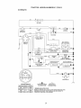
• Check wiring
See electrical
diagram in the Repair Parts
cause
running,
of
systems, which are being done at the
customers expense, may be performed
by any non-road engine repair establishment or individual_ Warranty repairs must
be performed by an authorized engine
manufacturer's
service outieto
TO ADJUST THROTTLE
CONTROL
CABLE
Door"'z_,:.".
:'
Terminal _ _
Guard
.J
repair, or replacement
control devices and
or
Throttle Cable
Screw Swivel
wiring
section.
FUSE
Replace with 15 amp automotive-type
plug-in fuse,, The fuse holder is located
behind the dash,
TO REMOVE
ASSEMBLY
• Raise
HOOD
AND
Goverl .=dIdle Spring
(Red or White)
GRILL
TO ADJUST
hood_
reverse
above
CONTROL
The choke control has been preset at the
factory and adjustment should not be
necessary, Check adjustment
as described below before loosening cable, If
adjustment is necessary, proceed as
follows:
• Unsnap headlight wire connector,
• Stand in front of tractor. Grasp hood at
sides, tilt toward engine and lift off of
tractor.
• To replace,
CHOKE
Stop
procedure.
25
. With engine not running, move choke
control (located on dash panel) to full
choke position
• Loosen knob and remove cover
• Continue to hold throttle lever against
idle speed screw and adjust idle
speed screw to obtain t200 RPM, if
the governed idle spring is red, or 900
RPM, if the governed idle spring is
white. Release throttle lever.
assembly from air cleaner.
• Choke should be closed. If it is not,
loosen casing clamp screw and move
choke cable until choke is completely
closed. Tighten casing clamp screw
securely.
• Replace air cleaner cover assembly
and tighten knob_
TO ADJUST CARBURETOR
ACCELERATION
TEST-
• Move throttle control lever from slow to
fast position,
If engine hesitates or
dies, turn idle mixture screw out
(counterclockwise)
1/8 turn.. Repeat
test and continue to adjust, if necessary, until engine accelerates
smoothly.
High speed stop is factory adjusted,
Do
not adjust - damage may result,.
IMPORTANT:
Never tamper with the
engine governor, which is factory set for
proper engine speed,
overspeeding
the
engine above the factory high speed
setting can be dangerous,
if you think
the engine-governed
high speed needs
adjusting, contact your nearest authorized service center!department,
which
has proper equipment
and experience
to
make any necessary adjustments.
The carburetor has been preset at the
factory and adjustment
should not be
necessary.
However, minor adjustment
may be required to compensate
for
differences
in fuel, temperature,
altitude
or load
If the carburetor does need
adjustment,
proceed as follows:
In general, turning the mixture screw in
(clockwise)
decreases the supply of fuel
to the engine giving a leaner fueltair
mixture. Turning the mixture screw out
(counterclockwise)
increases the supply
of fuel to the engine giving a richer fuel/
air mixture.
Choke Closed
IMPORTANT:
Damage to the needles
and the seats in carburetor may result if
screw is turned in too tight.
PRELIMINARY
SETTING -
.Z__.________/--]
I {
Cramp
. Be sure you have a clean air filter, and
the throttle control cable and choke
are adjusted properly (see above).
• With engine off turn idle mixture screw
in (clockwise)
closing it finger tight and
then turn out (counterclockwise)
1-114
to I-t/2 turns..
FINAL SETTING
Throttle
-
• Start engine and allow to warm for five
minutes.
Make final adjustments
with
engine running and shift/motion
control lever in neutral (N) position.
. With throttle control lever in slow
position, hold throttle lever against idle
speed screw and adjust idle speed
screw to obtain 1300 to t500 RPM°
• While still holding throttle lever against
idle speed screw, turn idle mixture
screw in (clockwise)
until engine
begins to die and then turn out
(counterclockwise)
until engine runs
rough.. Turn screw to a point midway
between those two positions,
Idle Mixture
Screw
26
idle Speed
Screw
Immediately
prepare your tractor for
storage at the end of the season or if the
tractor will not be used for 30 days or
more..
CAUTION:
Never store the tractor
with gasoline in the tank inside a
building where fumes may reach an
open flame or spark. Allow the engine to
cool before storing in any enclosure.
filter, fuel hose, or tank during storage,
Also, experience
indicates that alcohol
blended fuels 9called gasohot or using
ethanol or methanol) can attract moisture
which leads to separation
and formation
of acids during storage Acidic gas can
damage the fuel system of an engine
while in storage.
. Drain the fuel tank.
"IF'ACTOR
• Start the engine and let it run until the
fuel lines and carburetor are empty,
• Never use engine or carburetor
cleaner products in the fuel tank or
permanent damage may occur,
• Use fresh fuel next season.
Remove mower from tractor for winter
storage.
When mower is to be stored for
a period of time, clean it thoroughly,
remove all dirt, grease, ieaves, etc. Store
in a clean, dry area..
• Clean entire tractor (See "CLEANING"
in the Maintenance
section of this
manual),
• Inspect and replace belts, if necessary
(See belt replacement
instructions
in
the Service and Adjustments
section of
this manual).
• Lubricate as shown in the Maintenance section of this manual.
• Be sure that all nuts, bolts and screws
are securely fastened.
Inspect moving
parts for damage, breakage and wear.
Replace if necessary.
• Touch up all rusted or chipped paint
surfaces; sand tightly before painting.
BATTERY
• Fully charge the battery for storage.
• After a period of time in storage,
battery may require recharging.
• To help prevent corrosion and power
leakage during long periods of
storage, battery cables should be
disconnected
and battery cleaned
thoroughly (see "TO CLEAN BATTERY
AND TERMINALS"
in the Maintenance
section of this manual).
• After cleaning, leave cables disconnected and place cables where they
cannot come in contact with battery
terminals_
• If battery is removed from tractor for
storage, do not store battery directly on
concrete or damp surfaces.
ENGINE
FUEL SYSTEM
IMPORTANT:
gum deposits
fuel system
it is important to prevent
from forming in essential
parts such as carburetor,
NOTE: Fuel stabilizer is an acceptable
alternative in minimizing
the formation of
fuel gum deposits during storage.
Add
stabilizer to gasoline in fuel tank or
storage container_ Always follow the mix
ratio found on stabilizer container.
Run
engine at least 10 minutes after adding
stabilizer to allow the stabilizer to reach
the carburetor°
and carburetor
ENGINEOIL
Drain oil (with engine warm) and replace
with clean engine oil_ (See "ENGINE" in
the Maintenance
section of this manual).
CYLINDER(S)
• Remove spark plug(s),
• Pour one ounce of oil through spark
plug hole(s) into cylinder(s)o
• Turn ignition key to "START" position
for a few seconds to distribute oit.
, Replace
with new spark plug(s)o
OTHER
• Do not store gasoline
to another.
from one season
• Replace your gasoline can if your can
starts to rust. Rust andtor dirt in your
gasoline will cause problems_
• If possible, store your tractor indoors
and cover it to give protection from
dust and dirt.
• Cover your tractor with a suitable
protective cover that does not retain
moisture.
Do not use plastic° Plastic
cannot breathe which allows condensation to form and will cause your
tractor to rust°
IMPORTANT:
Never cover tractor while
engine
fuel
Do not drain the gas tank
if using fuel stabilizer.
27 warm
and exhaust
areas
are still
TROUBLESHOOTING
CHART
[.........
PROBLEM
Will not start
CORRECTION
CAUSE
• Out of fuel.
• Engine not "CHOKED"
properly.
• Engine flooded,
•
.
•
.
Bad spark plug.
Dirty air filter.
Dirty fuel filter.
Water in fuel
• Loose or damaged
wiring,
• Carburetor out of
adjustment,
• Engine valves out of
adjustment,
Hard to start
. Dirty air filter.
• Bad spark plugo
• Weak or dead battery,,
. Dirty fuel filter.
• Stale or dirty fuel.
Loose or damaged
wiring.
Carburetor out of
adjustment.
•Engine valves out of
adjustment,
Engine
)ver
will not turn
• Clutchfbrake
pedal not
depressed.
• Attachment clutch is
engaged.
• Weak or dead battery.
• Blown fuse.
• Corroded battery
terminals.
• Loose or damaged
wiring,
, Faulty ignition switch°
• Faulty solenoid or
starter_
• Faulty operator
presence switch(es).
Engine clicks but will
not start
. Weak or dead battery,
• Corroded
terminals,
battery
28
• Fill fuel tank.
• See "TO START ENGINE"
in Operation section.
- Wait several minutes
before attempting to start,
• Replace spark plug.
- Cleanlreplace
air filter,
Replace fuel filter,,
• Drain fl_el tank and
carburetor, refill tank with
fresh gasoline and replace
fuel filter
• Check all wiring.
• See "To Adjust Carburetor"
in Service Adjustments
section,
• Contact an authorized
service center/department.
• Cleanlreplace
air filter.
• Replace spark plug.
• Recharge or replace
battery,,
• Replace fuel filter,
• Drain fuel tank and refill with
fresh gasoline.
• Check all wiring.
• See "To Adjust Carburetor"
in Service Adjustments
section,,
• Contact an authorized
service centerldepartment.
• Depress
clutchtbrake
pedal,
• Disengage attachment
clutch.
. Recharge or replace
battery.
. Replace fuse.
• Clean battery terminals,,
• Check
all wiring,
• Check/replace
ignition
switch.
. Checldreplace
solenoid or
starter.
. Contact an authorized
service centeridepartment_
• Recharge or replace
battery.
• Clean battery terminals.
TROUBLESHOOTING
PROBLEM
CHART
CAUSE
Engine clicks but witl
not start (Cont'd)
Loss of power
CORRECTION
- Loose or damaged
wiring
• Faulty solenoid or
starter,,
• Cutting too much
grass/too fast.
• Throttle in "CHOKE"
position_
• Build-up of grass,
leaves and trash
under mower.
• Dirty air filter,,
. Low oil leveltdirty oi!,
• Faulty spark plug.,
• Dirty fuel filter,
° Stale or dirty fuel.
. Water in fuel,,
. Spark
plug wire loose,
. Dirty engine air screen/
fins,
. Dirtylctogged
muffler.
• Loose or damaged
wiring.
• Carburetor out of
adjustment,
• Engine valves out of
adjustment,
Excessive
vibration
• Worn, bent or loose
blade.
• Bent blade mandrel.
• Looseldamaged
part(s).
Engine continues
to run when operator
leaves seat with
attachment
clutch
engaged
• Faulty operator-safety
presence control
system.
Poor cut - uneven
• Worn, bent or loose
blade.
° Mower deck not level.
• Buildup of grass,
leaves, and trash
under mower.
• Bent blade mandrel.
• Clogged mower deck
vent holes from buildup
of grass, leaves, and
trash around mandrels.
29
• Check
all wiring,
. Check/replace
starter,
e
i
solenoid
or
Set in "Higher Cut" position/
reduce speed,
Adjust throttle control,
Clean
underside
of mower
housing°
• Cleanlreplace
air filter,
• Check oil ieveltchange
oil.
• Clean and regap or change
spark plug.
• Replace fuel filter.
• Drain fuel tank and refill
with fresh gasoline.
. Drain fuel tank and carbure
tor, refill tank with fresh
gasoline and replace fuel
filter_
• Connect and tighten spark
plug wire.
• Clean engine air screenlfins.,
• Clean/replace
muffier_
• Check all wiring,
• See "To Adjust Carburetor"
in Service Adjustments
section
. Contact an authorized
service center/department,
• Replace blade° Tighten
blade bolt..
- Replace blade mandrel°
• Tighten loose part(s).
Replace damaged parts,,
Check wiring, switches
and
connections.,
If not corrected,
contact an authorized
service center/department.
• Replace blade, Tighten
blade bolt.
° Level mower deck°
° Clean underside of mower
housing.
Replace blade mandrel,
Clean around mandrels to
open vent holes_
TROUBLESHOOTING
CHART
PROBLEM
CAUSE
Mower blades will not
rotate
Poor grass discharge
CORRECTION
. Obstruction
in clutch
mechanism,,
• Worn/damaged
mower
drive bell
Remove obstruction°
Replace
mower
, Frozen
• Frozen
idler pulley,
blade mandre!.
Replace
Replace
idler puIley.
blade mandrel.
o Engine
speed too slow.
• Travel speed too fast.
. Wet grass
• Mower deck not level.
• Low/uneven
tire air
pressure°
• Worn, bent or loose blade.
• Buildup of grass,
leaves and trash under
mower.
• Mower drive belt worn,_
• Blades improperly
installed
" Improper blades used,,
• Clogged mower deck
vent holes from buildup
of grass, leaves, and
trash around mandrels.
Headlight(s) not
working (if so
equipped)
Battery will not charge
Engine
"backfires"
when turning
"OFF"
engine
.
•
•
•
Switch
Bulb(s)
Faulty
Loose
wiring
• Blown
is "OFF",_
burned out.,
light switch,
or damaged
fuse.
• Bad battery cell(s),
• Poor cable connections°
drive belt.,
• Place throttle control in
"FAST" position,
. Shift to slower speed_
• Allow grass to dry before
mowing.
• Level mower deck,
• Check tires for proper air
pressure,
• Replacelsharpen
blade,
Tighten blade bolto
• Clean underside of mower
housing.
• Replace mower drive belt.
Reinstall blades sharp edge
down,
Replace with blades listed
in this manual.
Clean around mandrels to
open vent holes,
• Turn switch "ON".
• Replace bulb(s).
• Check/replace
light switch.
• Check wiring and connec
tions,
• Replace fuse,
• Replace battery.
• Checktclean
all connec
tions,,
• Replace regulator.
. Faulty regulator (if so
equipped)
• Faulty alternator,
• Replace
• Engine throttle control
not set at "SLOW"
position for 30 seconds
before stopping engine.
• Move throttle control to
"SLOW" position and allow
to idle for 30 seconds before
stopping engine_
alternator.
....
3O
,
i
TRACTOR
-- MODEL N UMBER 9I 7.270813
SCHEMATIC
BATTERY
RED
FUSE
AMMETER
(OPTIONAL)
I ....
{ ....
I
I
L __-=
----(
)G
STARTER
t
BLACK
E
J
CLUTCH ! BRAKE
(PEDAL UP)
L
WHITE
IGNITION
SWITCH
I -- -
_
OCCUPIED)
'
2
L
,
I
BLACK
/7
BLACK
"_
F_
A
HOUR
METER
I'_
_J
(OPTIONAL)
o
--_-;,T_I
I _____U=L_
',
'4_" LINE,
)J
ATT'MENT CLUTCH
BLACK (CLUTCH OFF)
[_
_
BLACK F_
_
[
"
j
_
_
IGNITION
UNIT
_
GROUNDING
CONNECTOR
Z"
_
[
_
r
{
I
'
_
REGULATOR
2ElVOLTS
AC @ 36_)0 RPM
_ [REGULATORDISCONNECTEO)
_
_
.........
'
..........
- - -
;ALTERNATOR',
BROWN
HF__ADLIGHTS
@
SWITCH
POSITION CIRCUIT
"MAKE"
OFF
G +M + L
RUN/LIGHT B + L
NONE
A+ Y
RUN
START
B+ L
B+ L + S
NONE
NONE
©
NON-REMOVABLE
CONNECTIONS
WIRING INSULATED
REMOVABLE
CONNECTIONS
CLIPS
NOTE: IF WIRING INSULATED CLIPS WERE REMOVED FOR
SERVICING OF UNIT, THEY SHOULD BE REPLACED TO
PROPERLY SECURE YOUR WIRING
3!
_'
1 _> : _J_-_J_>-_--_
_-_
3"
IGNITION
,!
SPARK
PLUG
_
GAP
_ .......
(2 PLUGS ON
_!H CyL ENG!NES)
CHARGING
SYSTEM
OUTPUT
., 16 AMP DO @ 361}t3RPM
]H x____.__..J
L_-J_L-_--_
FUEL SHUT-OFF
SOLENOID
_
_-
TRACTOR
-- MODEL NUMBER
ELECTRICAL
I
J
I
I
14
_
26
1
t
t
t
I
31
f
!
29
12
32
917.270813
TRACTOR
-- MODEl.° NUMBER
917.270813
ELECTRICAL
KEY PART
NO. NO.
t
2
8
10
11
12
16
t9
20
2I
22
24
25
26
27
28
29
30
31
32
33
40
41
42
43
45
52
55
70
163465
74760412
7603J
145211
150109
145769
153664
STD55t125
73350400
166182
4t52J
4799J
146146
166180
73510400
145491
12!305X
140301
1242tlX
141226
!09310X
166145
71110408
131563
145673
73640400
122822X
141940
17490508
166660
NOTE:
DESCRIPTION
Battery 12 Volt 28 Amp
Bo]t Hex Hd 114-20unc X 3/4
Case Battery
Bolt, Btr Front tf4-20 x 7-1t2
Holddown Battery Front Mount
Nut, Push Nylon Battery Front 1/4
Switch Interlock Push-in
Washer Lock 1t4
Nut Jam Hex 1/4-20 Unc
Harness Asm Light Wf4152j
Bulb Light #t 156
Cable Battery 6 Ga I 1"red
Cable Battery 6 Ga red wt16 wire
Fuse 15 AMP
Nut Keps Hex !I4-20 Unc
Cable Ground 6 Ga 12"black
Switch Plunger Nc Gray
Switch lgn
Nut Ignition
Cover Sw Key Blk 1 25 Text SLT
Key Molded Craftsman
Harness lgn LT
Bolt BIk Fin Hex 1/4-20 Unc x 112
CoverTermina! Red
Solenoid
Nut Keps Bik Hex 1f4-20 Unc
Ammeter Rectangular t5 Amp
Protection Wire Loop
Screw Thdrol 5t16-18 x 112
Harness Eng
All componenl
dimensions
inches t inch = 25t4 mm
33
given in U S
TRACTOR
-- MODEL NUMBER
917.270813
CHASSIS AND ENCLOSURES
29
28
5B
12
37
14
39
34
TRACTOR
-- MODEL NUMBER
917.270813
CHASSIS AND ENCLOSURES
KEY PART
NO+ Nee
DESCRIPTION
I
2
3
4
5
9
t0
11
12
13
14
17
18
20
23
25
26
28
29
30
31
37
38
39
51
52
53
54
55
57
58
,60
64
74
1t4
115
I16
t40
142
I43
t44
t45
Chassis Assembly
Drawbar
Screw 3/8-16 x 75
Washer 13132x 3/4 x 16 Ga
Bumper HoodfDash
Dash
Bolt Carreage 3t8-16 x '1
PanetAsm Dash Lh
Clip Tinnerman Grille PIL
Panel Dash Rh
Screw Thdrol, 3t8-16 x ti2 Ty-Tt
Hood Assembly
BumperHood
Plate Mtg, BaterytFuel Tank Fr
Bushing Snap Ny[ BIk Fuel Line
Washer 13./32 x 13/16 x 12 Ga..
Nut Lock Hex w/Ins 3/8-16 Unc
GrillelLens Asm
Lens Griile
FenrJertFootrest
Bracket Fender Support
Screw Thdro[ 5ft6-18 x 112Tyt
Bracket Asm., PvL Lh Mwr.+Rear
Bracket Asm Pvt. Rh Mwr. Rear
Nut Lock Hex W/Ins 114-20
Washer 9/32 x 7/8 x 16 Ga
Bracket Gritle LH
Screw Hex Wshd 8-18 x 7/8
Bracket. Grilte RH
Bolt Fin Hex I14+20x 3/4
Duct Air Engine PLILT
Bolt Rdhd Sqnk 318-16 x Unc x 314
Dash Lower STLT
Nut Crownlock 318-16UNC
Keeper Belt rear Lh St!
Screw Thrdot 318-t6 x 1-1/4
Washer 13132x t x 14 Ga,
Bracket Front Suspension
Plate ReinforcementSTLT
Bracket Swaybar Chassis
Bracket Pnt Footrest STLT
Rod Pivot ChassisfHeod
166819
140356
17060612
STD551025
155272
1619t7X013
STD533710
155927
145680
169118
17490608
I44983X558
126938X
156437
t24028X
191313t2
738O0600
156725X558
155217X599
151287X558
139976
17490508
139886
139887
73800400
19091416
1452O1
161464
145202
STD522507
15O127
STD533707
154798
STD541437
158112
17490620
19131614
158418
165867
154966
154207
156524
NOTE: All component dimensions given in U S
inches 1 inch = 25t4 mm
35
TRACTOR--MODEL
GROUND
NUMBER
917,270813
DRIVE
57
22
36
26
27
TRACTOR
-- MODEL NUMBER
9t7.270813
GROUND DRIVE
KEY
NOo
t
2
3
4
5
6
8
!0
1t
13
14
18
19
21
22
24
25
26
27
28
29
30
31
32
34
35
36
37
38
39
40
41
42
47
48
49
50
51
52
53
55
56
57
58
PART
NO.
......
146682
123666X
12000028
I21520X
17060512
165866
STD56t210
105701X
7455O412
STD551t25
STD523710
STD541437
I06933X
130804
STD541237
106888X
STD551037
STD561210
145204
124236X
130807
127275X
STD523107
155071
I20183X
STD55t062
STD5718t0
131494
STD523727
4470J
165838
19131312
127783
1544O7
!23205X
STD523715
STD541437
STD54143I
105710X
105709X
STD523712
13080t
127274X
KEY PART
NO. NO.
59 140312
61 17060612
62 8883R
63 140186
64 71t70764
65 STD55t143
66 154778
70 134683
72 19132012
74 137057
75 t21749X
76 STD581075
77 123583X
78 121748X
79 STD580025
80 145090
8t 165592
82 165711
83 19171216
84 166231
85 '150360
89 '15839tX428
90 124346X
96 STD624003
112 19091210
113 127285X
116 72110610
145 74490540
150 165850
151 19133210
156 166002
157 153236
158 165589
159 165494
!60 19292016
t61 72140406
'!62 73680400
163 74780416
!64 19091010
165 165623
166 166880
I68 165492
169 165580
DESCRIPTION
Transaxie (See Breakdown)
Peerless 206-545C
Spring Return Brake
Pulley Transaxle
Ring Retatner
StrapTorque 30 Degrees
Screw 5116-18 X 3/4
Rod Shifter Fender STLT
Pin Cotter It8 X t
Washer Piate Shf 388 Sq Hole
Bolt If4-28 UnfGr 8 WIPatch
Washer Lock 114
Bolt Fin Hex 3/8-16 uric X I Gr, 5
Nut Lock Hex Wtlns 3/8-16 Unc
Knob Rd 1/2-t3 Pfstc Thds BIk
Rod BrakeLT
Nut Hex Jam 3/8-!6
Spring Rod Brake 2 00 Zinc
Washer t3t32 X 13II6 X 16 Ga
Pin Cotter t18 X 3/4 Cad
Rod Brake Parking LT/YT
Cap Brake Parking Black
Bracket Transmission
Keeper Belt LH LT 14 Ga
Bolt He× 5tt6-18 x 3/4
Shaft Asm Pedal Foot
Bearing Nylon BIk 629 Id
Washer 21132 X t X t6 Ga
Pin Roll 3t16 X 1"
Pulley idler Flat
Bolt Fin Hex 3f8-16unc X 24314
Spacer Spilt 395 X 59 Bzp
Keeper Bait idler
Washer t3t32 X 13t16 X I2 Ga
Puiley Idler V Groove Plastic
Bellcrank Clutch Grnd Drv STL
Retainer Belt Style Spring
Bolt Hex Hd 318-16unc X t-I/2
Nut Crownlock 3f8-16 Unc
NutCrown!ock 5116-I8
Link Clutch 7 66
Spring Return Clutch 6 75
Bolt Fin Hex 3/8-t6 UNC x 1-114
V-Belt Ground Drive
Keeper Belt RH LT Pnt/zinc 16g
DESCRIPTION
Keeper Bett Chassis Span Ctr
Screw 3/8-16 x 75
Cover Pedal BIk Round
Engine Pulley LT/YT
Bolt Hex 7/16-20x4 Gr 5
Washer Lock Hvy Hlcf Spr 7/t6
Keeper Belt Engine
Guide Belt Mower Drive RH
Washer 13/32 X 1-I/4 X 12 Ga
Spacer Axle
Washer 25132 X 1 1t4 X 16 Ga
E-ring
Key Square 2 0 X 18451I885
Washer 25132 X 't-5t8 X 16 Ga
Key Woodruff
Arm shift
Shaft Assembly
Spring, Torsion
Washer 17/32 x 3t4 x 16 Ga
Transaxle Link
Nut. Nylock
Console, Shift, STLT
Nut, Self-Thding, Wsh Hd ti4
Retainer Spring 1"
Washer 9f32 X 3f4 X 10 Ga
Strap Torque 90 Degrees
Bolt Rdhd Sq Neck 3t8-16 x t,25
Bolt Hex FLGHD 5f16-18 Gr. 5
Bushing Beilcrank Grd Dr SlllLt
Washer 13/32 x 2 x t0 Ga.
Washer Srrted 51161Dx 1..125
Bolt Shoulder 5/16-18 Unc - 2A
Bracket Shift Mount
Hub Tapered Fiange Shift Lt
Washer 29/32 x 1-114x 16 Ga
Boil Rdhd Sqnk II4-20 x 314 Gr 5
Nut Crownlock I/4-20 Unc
Bolt Hex Fin !f4-20 Unc x 1 Gr 5
Washer 5f8 x .28t x t0 Ga
Bracket Pivot Lever
Screw 5/!6-18 x 5t8
Bolt Shoulder 5t16-18 x 561
Plate Fastening Lt
NOTE: All component dimensions given in U S
inches 1 inch = 2514 mm
37
T RACTOI_
"" MODEL NUMBER
STEERING
+ .......
,_.......
,.
1
.,
+-_
t
82
tl
\
,/
\
/
'\
/
/
4O
'\
\
,r29
15
38
917.270B13
TRACTOR
-- MODEL NUMBER
917,270813
STEERING
KEY PART
NO, NO,
DESCRIPTION
1
2
3
4
5
6
7
8
9
10
11
13
15
17
18
19
22
23
25
26
27
28
29
30
32
36
37
38
39
40
41
42
43
44
46
47
5t
54
62
63
65
66
67
68
79
80
Wheel Steering
Axle Asm Fr LT Wlgzks 38142
SpindleAsm LH
SpindleAsm RH
WasherThrust .75 x 1,230
Washer 25f32 X 1-5t8 X 16 Ga
Washer 27132 X 1-t!4 X !6 Ga
Ring Klip #t5304-75
Bearing Col Strg Btk
Link Drag Extended Stamped
Washer Lock Hvy Hlcl Spr 3/8
Bearing Axle
Nut Lock Flange 5/8-11 Unc
Shaft Asm Strg Private Label
Washer Thrust 515x 750x 033
Support Shaft Steering
Screw Hex WshHd Torx
Shaft Asm Pittman
Bracket Steering
Bushing Link Drag Bik Lr
Gear Sector 22 Teeth
Washer 13/32 x 7f8 x 16 Ga
Screw 318-t6 x,,75
Pin Cotter t/8 x 3t4 Cad
Rod Tie Wire Form t9 75 Mech
Bushing Steering
Screw
Cap Wheel Steer Ayp
Washer 13132x 2-3t8 x 12 Ga
Nut, Lock Center 3/8-24 UNF
Adapter Wheel Strg
Boot Steering
Washer 25132 X 1 114X t6 Ga
Extension Steering PtL
Cap Spindle Fr Top Blk
Fitting Grease
Nut Lock Hex Wllns, 5116-18 Unc P
Bolt Fin Hex 5116-18 Uric 6 x 1-1/4
Kit Steering Assembly
Bolt Fin Hex 318-16unc x 1 Gr 5
Spacer Axle
Bearing Arm Pittman
Bolt Fin Hex 5f8-11 X 2-3t4
Brace Axle
Washer 13f32 x 1-1f4 x '12Ga
Bolt Hex Nylon 3/8-16 x 3!4
139768
154427
t56483
t57473
6266H
121748X
I9272016
12000029
3366R
156438
STD551!37
154779
73901000
156546
57079
160395
165857
165851
154406
126847X
136874
19131416
17060612
STD56t210
130465
155099
152927
139769
19133812
STD541437
t00711L
145054
I21749X
153720
t2t232X
6855M
STD541431
74780520
167902
STD523710
154780
154404
74781044
154429
19132012
74950612
NOTE: All component dimensions given in U S
inches 1 inch = 25t4 mm
39
TRACTOR
--MODEL
NUMBER
917.270813
ENGINE
2
13
I0
14
81
78
32
34
3I
/
23
/
39
29
4
OPTIONAL
EQUIPMENT
Spark Arrester
Re
Spl
4O
TRACTOR
-- MODEL NUMBER
917.270813
ENGINE
KEY PART
NO. NO,
t
2
3
4
5
6
7
8
t0
13
t4
!5
16
23
25
26
29
31
32
33
34
35
37
38
39
78
81
103
162153
I77204t0
149723
122434X
122435X
138t29
150176
145552
805024
13280336
13200300
STD551237
159880
145996
73920600
137180
157103
161696
123487X
106082X
17060512
8543R
.......
109227X
17490620
128861
805158
DESCRIPTION
ControtThrotPaddle3600
Screw Hex Thd Cut 1t4-20x518
Engine B&S Model 350777-1034-A'1
(See Breakdown)
Muffler Exhaust
Tube Manifold Lh
Tube Manifold Rh
ClampTubeDouble Engine
Bolt 5t16-18unc x 314wtsems
Heat Shield Lt
Gasket Manifold vanguard B&S
Nipple Pipe 4-112"
Elbow Std 90 Degree 3/8-t8 Npt
Washer Lock Ext Tooth 3!8
Shield BrnlDbrGuard
Control Choke
Nut Keps 3!8-24 UNF
Arrestor Spark
Tank Fuet
Cap Fue]Guage
Clamp Hose BIk
Spacer, Pad
Screw 5t16-18 x 3t4
Line Fuel
Plug Oil Drain (See Engine Breakdown)
Pad Idler
Screw Thdrof 3/8-16 x 1-1/4 Tytt
Nut Flange 114-20 Starter Nut
Screw Manifold Vanguard B&S
NOTE: All component dimensions given in U S,
inches t inch = 25/4 mm
4!
TRACTOR
-- MODEL NUMBER
917.270813
SEAT ASSEMBLY
10
5
25
11
12
KEY PART
NOo NOw
t 140123
2 140551
3 STD523710
4 19131610
5 145006
6 STD541437
7 124181X
6 17060616
9 19131614
!0 155925
tl 166369
12 I21246X
KEY
NO.
DESCRIPTION
Seat
Bracket Pivot Seat 8 720
Bolt Fin Hex 3/8-16unc X t
Washer t3132 X 1 X t0 Ga
Clip Push-In Hinged
Nut Hex Lock wllns 3t8-t6 Unc
Spring Seat Cprsn 2 250 B!k Zi
Screw Thdro1318-I6 X 1.5
Washer 13132X 1 X !4 Ga
Pan Seat
Knob Seat Adj Wingnut
Bracket Mounting Switch
13
14
t5
16
t7
21
22
24
25
PART
NO,
121248X
72050412
134800
121250X
123976X
153236
STD541431
19171912
127018X
DESCRIPTION
Bushing Snap Blk Ny150 Id
Bolt Rdhd Sht Nk !f4-20x1-II2
Spacer Split 28x 96 Yel Zinc
Spring Cprsn 127 Btk Pnt
Nut Lock 114Lge Fig Gr 5 Zinc
Bolt Shoulder 5f16-t8 Unc
Nut Crown Lock 5f16-18
Washer 17t32 X t-3!16 X !2 Ga
Bolt Shoulder 5116-18 X 62
NOTE: Allcomponent dimensions given in U, S
inches 1 inch = 25!4 mm
42
TRACTOR
-- MODEL NUMBER
917.270813
DECALS
9
13
,5
0
t5
KEY PART
NO. NO.
I 156439
2 160876
3 163200
4 163202
5 163207
6 133644
7 163259
9 163204
t0 160879
tl
156368
WHEELS
....
i
i
i /
5
KEY PART
NO. NO.
I2 160880
13 146046
15 160396
19 138047
20 166887
22 149516
-13831!
DESCRIPTION
Decal Fender Danger Sears
Decal, Engine B&S
Decal Hood RH Craftsman
Decal Hood LH Craftsman
Decal Fender
Decal Maintenance
Decal Panel Dash
Decal, Fender Craftsman Gold
Decal engine Radius
Decal Fender STLT Oper Ins{
-----
154515
154516
169461
169462
KEY PART
NO. NO.
AND TIRES
t
2
3
4
5
6
7
59192
65139
106222X
59904
t06732X427
278H
9040H
8
9
10
tl
--
t06108X427
t22082X
7152J
t04757X
144334
DESCRIPTION
Decal engine Air Cleaner
Decal V-Belt Dr Sch tractor
Decal Mower Drive Schem
Decal Battery Diehard Sears
Decal Deck Mower EZ3
Decal Battery
Decal Handle Lft Height Adjust
(Lift Handle)
Pad Foolrest LH STLT
Pad Footrest RH STLT
Owner's Manual, English
Owner's Manual Spanish
DESCRIPTION
Cap Valve Tire
Stem Valve
Tire F Ts 15 X 6 0 - 6 Service
Tube Front (Service Item Only)
Rim Asm 6"front White Service
Fitting Grease (Front Wheel Only)
Bearing Flange (front Wheel
Only)
Rim Asm 8"rear White Service
Tire Rear
Tube Rear (Service Item Only)
Cap Axle Bfk 1 50 X 1 00
Sealant, Tire ( 10 oz, Tube)
NOTE: Alfcomponentdimensions
givenin U S,
inches 1 inch = 25!4 mm
43
TRACTOR--
MODEL NUMBER
917.270813
LIST ASSEMBLY
28
27
25 24
23
49
5
3O
3
\
13
26
6
19
I
1
13
2O
15
44
TRACTOR
--MODEL
NUMBER
917.270813
LIST ASSEMBLY
KEY PART
NO. NO.
1
2
3
4
5
6
7
8
11
t2
13
15
16
17
18
t9
20
23
24
25
26
27
28
29
30
3t
32
49
50
t59460
159471
I05767X
12000002
19211621
120183X
12563tX
122365X
139865
139866
STD624008
127218
73350800
130171
73680800
139868
163552
110807X
19131016
2876H
76020308
!26971X
73350600
138057
150233
140302
73540600
145212
110452X
DESCRIPTION
WireAsm lnnertSprg WfplungerLT
Handleasm Lift LH
Pin Groove
ERing#5133-62
Washer PLTD 21f32 X 4X 21ga
Searing Nylon Slk 629 ld
GripHandle
Button P_ungerRed
Link Lift LH
Link Lift RH
Retainer Spring
Link Front
Nut Jam Hex 112-I3 Unc
Trunnion BtkZinc
NutCrownlock 112-13unc
Arm Suspension Rear
Retainer Spring
Nut, Special
Washer13132x5tSx
16Ga
Spring
Pin Cotter 3/32 x 1t2
Rod, Adjust Lift
Nut Hex Jam 318-16 Unc
Knob Inf 3t8-16
Trunnion, lnf Height
Bearing Pivot Spherical
NutCrownlock 318-24
Nut Flange Lock
Nut Push Phos & Oil
NOTE: Air component dimensions given in U S
inches 1 inch = 25/4 mm
45
TRACTOR
MOWER
-- MODEL NUMBER
917.270813
DECK
76
34
,33
32
t06_
102
103 105
17
\
t 02/_
21
!;
22
23
24
25
26
29
18
46
27
TRACTOR
MOWER
917.270813
DECK
KEY PART
NO. NO,
I 164961
2 STD533107
3 138017
4 138440
5 8TD624008
6 130832
8 850857
9 STD551137
10 140296
11
12
t3
!4
15
16
17
18
!9
20
21
22
23
24
25
26
27
28
29
30
3t
32
33
34
35
36
37
40
4I
43
44
45
46
48
49
50
51
52
53
54
55
-- MODEL NUMBER
134149
129895
137645
128774
110485X
140329
72110610
72140505
132827
159770
STD541431
134753
131267
105304X
1237t3X
110452X
130968
19111016
131491
157722
129963
153535
137266
STD5337t7
133835
131494
STD55t037
STD54t437
133551
140083
140088
STD624003
137729
133944
155066
131340
STD541410
139888
131845
133943
155046
KEY
NO.
DESCRIPTION
MowerHousing
Bolt Rdhd Sqnk 5t16-18unc X3f4
Bracket Asm Fr Sway Bar 38/42
Bracket Asm Deck 42" sway Bar
Retainer Spring
Arm Suspension Rear
Bolt 318-24 X 1 1/4
Washer Lock Hvy 3/8
WasherHard Blade Mower
Vented
Blade Mulching 42"
Bearing Balf
Shaft Asm W/lower Bearing
Housing MandrelVented
Bearing BallMandrel
Stripper MowerVented
Bolt Rdhd Sqnk 3/8-16 X i-tt4
Bolt Rdhd Sqnk 5116-18 X 518
Bolt Shoulder
Baffle Vortex 42
NutCrowntock 5t16-!8 UNC
Stiffener Bracket 42" deck
Bracket Deflector Mower 42"
Cap Sleeve 80x t 12 Blk Mower
Spring Torsion Deflector 2 52
Nut Push Phos & Oil
Shield Deflector Mower42" Btk
Washer t 1132X 516X t6 Ga
Rod Hinge 42" 6 75 Wlg
ScrewThdrolWasherHead
Washer Spacer Mower Vented
Pulley Mandrel 42144!50
Nut 9ft6 Top Lock Flng
Bolt Rdhd 3!8-16uncx1-3/4 Gr5
Fastner Christmas Tree
Pulley idler Flat 3 060
Washer t3132x 13/16 x 16 Ga
Nut Crownlock 3t8-16 UNC
Rod Pivot Wtnibs
Rod Clutch Secondary Wlnibs
Guard Mandrel LH Black
Spring Reta{ner I" Zinctcad
Screw Hex Thd Cut
Washer Hardened Smaller
Roller Asm Cam Follower 42" dec
Bolt Shldr 10-24 Zinc Gr 5 42"
Nut Lock #10-24 Unc
Bolt Shoulder 5/16-18 Unc Btkz
Arm Asm Pad Brake
Washer Hardened
Arm Idler42" mower LTtYT
PART
NO.
56 122052X
58 140086
59 141043
67 I62113
68 144200
71 142427
72 131870
73 127847
74 121748X
75 12000029
76 128903
77 127845
78 160570
79 127498
80 153701
81 73350600
82 142028
83 t20958X
84 '156084
85 72140620
92 STD541437
101 136420
102 71161010
103 1906t216
104 STD551110
!05 '160793
t06 2029J
111 155197
112 155t98
1t3 17060512
114 STD541431
115 72110504
116 4898H
117 165746
! t8 73930600
! 19 STD55t037
t21 143723
t28 t53390
129 19131312
130 STD523710
!31 STD533710
132 19132203
141 6266H
-130794
- -
164963
DESCRIPTION
Spacer Retainer Pm Mower
Spring Torsion Brakes 42"
Guard TUV Idler
Knob Oval
WBelt Mower
Rod CluLch Primary 38142
Spring Return
Arm Clutch Secondary
Washer 25!32 X t-518 X 16 Ga
Ring Klip #t5304-75
Bolt Shoulder 318-'t6 Unc ! 44
Keeper Spring 4 000
Lever Asm CL PRI MECH RH PIL
Bushing 747 Od X 794 Lg Brass
Spring Clutch Mower
Nut Hex Jam 318-t6 Unc
TrunnionAdj
Washer Sintered
Keeper Belt Idler
Bolt RHDH SQ 318-16 x 2-1t2
Nut Lock Hex Wtinx 3/8-16 UNC
Mulcher Cover
Screw
Washer#t0
Washer, Lock #10
Latch Assembly Bagger
NutWeld
Bracket Gauge Wheel LH
Bracket Gauge Wheel RH
Screw 5f16-18 X 314
Nut Keps 5116-18 Unc
Bolt Cart 5It6-unc X 1t2
Bait Shoulder
Wheel Gauge
Nut Crownlock 3f8-16 Unc
Washer 12/32 x 14t16 x 12 Go.
Brackel Extruded Gauge Wheel
Washer Felt
Washer 13132 X 13/16 x 12 Ga.
Belt Fin Hex 3f8-16 Unc x t Gr 5
Bolt RDHD SQNK 3/8-16 UNC x 1
SpacerWasher
13132 OD X 1-3t8 X I14
Washer Thrust
Mandrel Asm Service (Includes
Key Nos. 8-10, 12-15, 31 and 33)
Deck Serv (Std Deck - Order
seperately gauge wheel
components key nos 1 !1-t2'I )
NOTE: All component dimensions given in U S.
inches ! inch = 25/4 mm
47
TRACTOR
PEERLESS
-- MODEL NUMBER
TRANSAXLE--MODEL
NUMBER
917.270813
206-545C
5O
1B
/
4
52
61
2g
36
MODEL and SERIAL
NUMBERS HERE
48
157
TRACTOR
-- MODEL NUMBER
PEERLESS TRANSAXLE--MODEL
REF PART
NO, NO.
1
2
3
4
5
6
6A
7
8
8A
9
10
11
12
'13
772147
780086A
770128
776395
776409
778364
778369
778330
792180
792O47
784352
784378
778334
778309
778368
14
778368
15
17
t8
20
21
22
25
25A
26
27
28
29
77837O
786188
786102
792077A
792078
792079
792073A
792177
792125
792035
788040
780072
29A 780160
29B 780051
29C 780199
3O 78O108
31
780001
31A 780195
32
34
35
35A
36
37
38
39
40
788083
780194
780193
780197
790075
790007
799021
786026
792076A
917.270813
NUMBER 206-545C
REF PART
NO, NO.
DESCRIPTION
Transaxle Cover
Needle Bearing 5/8"
Transaxle Case
Countershaft
Output Shaft
Spur Gear (38 teeth)
Spur Gear (15 teeth)
Spur Gear (1! teeth)
Shift Key
Woodruff Key #9
Shlft Collar
Shift Rod & Fork
Bevel Gear (30 teeth)
Input Bevel Pinion (I3 teeth)
Bevel Gear (13 teeth)
(lnclude_ I4)
Bevel Pinion (13 teeth)
(Include 13)
Ring Gear (43 teeth)
Drive Pin
Spacer 1,130 X _695
Bal15116"dia
Set Screw 318 - 16 x 3/8"
Spring 310 OD x .625 L
Screw t/4 - 20 x 1-t/4"
Screw 1/4-20 x i-3/8"
Retaining Ring (pkg of 2)
Retaining Ring
Retaining Ring
Thrust Washer
.627 ID x O31W
Thrust Washer
,762 ID x 031W
Thrust Washer
762 ID x .031W
Anti-Rotation Washer _632
Cup Washer
1,127 ID x ,032W
Flat Washer
,750 ID x ,056W
(Use As Needed)
Fiat Washer
.750 ID x ,062W
Oil Seal 5/8"
Bushing .563
Flanged Bushing 5 / 8" ID
Flanged Bushing ,,751
Brake Disk
Brake Pad Plate
Brake Pad (pkg of 2)
Dowel Pin
Flat Washer
312 ID x ,059W
41A
42
42A
43
44
45
46
47
48
49
50
51
52
53
54
56
57
58
59
60
61
65
790079
792073A
792085A
792075
790025
786066
786086
774690
774691
778356
778338
778354
778352
778350
778346
778355
778337
778353
778351
778349
778345
780189
66
67
69
70
71
71B
76
776422
776396
792170
786187
788069
788092
780090
77
79
82
788078A
792144
778333
83
85
87
150
157
180
900
778338
792154
788089A
788093A
788088A
730229A
794712
NOTE:
49
DESCRIPTION
Brake Lever
Screw 1/4 * 20 x I-I/4"
Screw I/4 - 20 x 2 tt4"
Locknut 5 / 16 - 24
Brake Pad Holder
Spacer ,2625 x 1,0
Brake Lever Bracket
Axle (11-15 t 16" Long)
Axle (16 - 1 / 2" long)
Spur Gear (29 teeth)
Spur Gear (27 teeth)
Spur Gear (23 teeth)
Spur Gear (19 teeth)
Spur Gear (16 teeth)
Spur Gear (15 teeth)
Spur Gear (I1 teeth)
Spur Gear (t3 teeth)
Spur Gear (17 teeth)
Spur Gear (21 teeth)
Spur Gear (24 teeth)
Spur Gear (25 teeth)
Flat Washer
,563 ID x .062W
Input Shaft
Shifter & Brake Shaft
Retaining Ring
Spacer ,890
Square Cut Ring
"O" Ring
Flat Washer
1,128 ID x ,058W
Inverted Retaining Ring
Spring 430 OD x 5000 L
Bevel & Spur Gear
(30 & 13 teeth)
Spur Gear (27 teeth)
Oil Fill Plug
Oil Seal 9 t 16"
Liquid Gasket RTV Silicone
Oil Seal 3 t4"
Gear Oil 80W90
Replacement MST
206_545C Transaxle
All component dimensions given in
U,S_ _nches 1 inch = 25 4 mm
TRACTOR
BRIGGS & STRATTON
-- MODEL
ENGINE-MODEL
N UMBER 917.270813
NUMBER 350777, TYPE NUMBER 1034-A1
9
171
(_)7_
to
552
5S2A_81
24:
" REQUIRESSPECIALTOOLS'TO iNSTALL
(SEE REPAIRINSTRUCTIONMANUAL)
50
TRACTOR
BRIGGS & STRATTON
-- MODEL
ENGINE-MODEL
NUMBER
917.270813
NUMBER 350777, TYPE NUMBER
1034-A1
109t ,_
127
(5
127A
467
tj
35
947
788_>t _
_S27
_240
60!
51
_0_,_ 3S'_A
TRACTOR
BRIGGS & STRATTON
-- MODEL NUMBER
ENGINE-MODEL
917.270813
NUMBER 350777, TYPE NUMBER 1034-A 1
22
324
526
729
52
TRACTOR-BRIGGS & STRATTON
MODEL NUMBER
ENGINE-MODEL
917.270813
NUMBER 350777, TYPE NUMBER
°,,, ¢
883
53
1034-A1
TRACTOR-BRIGGS
KEY
Nee
PART
NO_
1
2
3
5.1
5.2
7
8
9
10
!1
I2
13
15
16
807787
805107
805101
B0782t
807822
805653
807795
805379
805751
805362
805112
805097
805048
807779
94196
807638
805049
805696
808132
805016
807888
18
20
22
23
24
25
807991
807992
807993
26
807889
807994
807995
807996
27
28
805099
807886
29
32
33
34
35
37
40
42
45
46
50
51
52
53
54
75
78
84
87
95
95A
98
104
105
807900
805395
805089
805090
805078
805506
805092
805161
262679
807542
805772
805700
805023
805669
805006
805007
805447
914889
805054
805561
94466
807705
805586
807706
& STRATTON
MODEL NUMBER
ENGINE-MODEL
DESCRIPTION
Cylinder Assembly
Bearing, Cylinder
*
Seal, Oil
Head, Cylinder, Cylinder #1
Head, Cylinder, Cylinder #2
**** Gasket, Cylinder Head
Breather Assembly
*
Gasket,Breather
Screw
Tube, Breather
*
Gasket, Crankcase Cover
Screw, Cylinder Head
Plug, Oil Drain
Crankshaft
Key, Timing Gear Retaining
Cover Assembly, Crankcase
*
Seal, Oil
Screw, Crankcase Cover
Flywheel, Magneto
Key, Flywheel
Piston Assembly, Standard
Size
Piston Assembly, .010"
Oversize
Piston Assembly, .020"
Oversize
Piston Assembly,
030"
Oversize
Ring Set, Piston, Standard
Size
Ring Set, Piston, ,010"
Oversize
Ring Set, Piston, °020"
Oversize
Ring Set, Piston, 030"
Oversize
Lock, Piston Pin
Pin Assembly, Piston,
Standard
Rod Assembly, Connecting
Screw, Connecting Rod
Valve, Exhaust
Valve, Intake
Spring, Valve
Cover, Starter
Retainer, Valve Spring
Retainer, Valve
Tappet, Valve
Gear, Cam
Manifold, Intake
*
Gasket, Carburetor Mounting
****Gasket, Intake Manifold
Stud, Carburetor Mounting
Screw, Sems
Washer, Spring
Screw, Sems
Plug, Pipe
Seal, Governor Shaft
Screw, Valve Mounting
Screw, Valve Mounting
Screw, Throttte Adjustment
** Pin, Float Hinge
** Fuel Inlet Assembly
NUMBER
KEY
NO.
917,270813
350777,
TYPE
PART
NO.
t08
805562
tt6
805058
116A805198
t168 224531
117 806109
It8
808374
t21
607708
122 805674
125 808372
127 805570
127A 805571
130 808572
131 808375
133 807710
137
---
NUMBER
1034-At
DESCRIPTION
Valve, Choke
O-Ring, Oil Pump
O-Ring, Crankcase Cover
Washer, Bowl
Jet, Main
Valve, idle Adjusting Needle
Carburetor Overhaul Kit
Spacer, Carburetor
Carburetor Assembly
Plug, Welch
Plub, Welch
Valve, Throttle
Shaft, Throttle Assembly
Float, Bowl
** Gasket, Bowl (Sold in Kit
Only)
t41 807711
Shaft, Choke
142 806110 ** Nozzle, Carburetor
Base, Air Cleaner
t61
807857
166 805343
Stud, Rocker Arm
t66A805073
Stud, Oil Filter Adapter
t67
805420
**** Washer, Valve Cover
171 805019
*** Nut, Ny_ock
187 393815
Hose, Fuel, 11" Long
296004
Hose, Fuel, 23" Long
(Cut to Required Length)
188 94627
Screw, Fan Retainer
Mounting
t88A 805247
Screw, Starter Mounting
t89
805449
Washer, Lock
192 807623
Screw, Valve Adjustment
(_ncludes Jam Nut)
20t
805480
Link, Governor
209 805462
Spring, Governor
209A805453
Spring, Governed Idle
216 805439
Link, Choke
Bracket, Governor Contro_
222 808195
227 807528
Lever Assembly, Governor
232 805465
Spring, Governor Link
240 493629
Filter, Fuel
243
805964
Screen, Oil
254 807713
Drain, Carburetor Bowl
265 221535
Clamp, Casing
Bracket, Choke Control
271
808145
Washer
277 805018
304 808220
Housing, Blower, Black
305 805406
Screw, Seres
307 805025
Screw, Seres
308
1808309
Cover, Air Guide, Cylinder
#1
308 2808098
Cover, Air Guide, Cylinder
#2
309 494990
Motor, Starting
310 94004
Bolt
*
**
***
....
NOTE:
54
*
*
**
**
**
Included in Gasket Set (807887)
Included in Carburelor Overhaul Kit
(807706)
included in Valve Overhaul Kit (807910)
Included in both Gasket Set (807887),
and Valve Overhaul Kit (807910)
Ali component dimensions
inches 1 inch = 25.4 mm
given in U.S.
TRACTOR
-- MODEL
BRIGGS & STRATTO N ENGINE.MODEL
KEY PART
NO, NOo
NUMBER
917.270813
NUMBER 350777, TYPE NUMBER
DESCRIPTION
324 494439
Screen, Rotating
332 806028
Nut, Hex
333 492341
Armature, Magneto
334 806104
Screw, Mounting
337 491055
Plug, Spark
351 805169
Screw, Hex Head
353 94791
Washer, Lock
353A806101
Washer, Lock
354 90576
Nut, Hex
354A 810078
Nut, Hex
356 493792
Wire, Ground
358 807887
Gasket Set
363 19203
Puller, Flywheel
387 808322
Pump, Fuel
423 805260
Screw, Sems
445 394018
Cartridge, Air CIeaner
467 491875
Knob, Air Cleaner
474 393295
Stator, Alternator
501 394890
Regulator, Alternator
510 495878
Drive Assembly
513 398003
Clutch Assembly
520 93722
Terminal, Spade
523 807985
Dipstick
524 80501t
Seal, Filler Tube
525 80761 t
Tube, Oil Filler
526 805448
Screw, Regulator Mounting
527 223167
Clamp, Fuel Pipe
535 272490
Element, Foam
537 805655
*
Gasket, Air Cleaner
544 490309
Armature Assembly
552 805412
Bushing, Governor Shaft
552A 805413
Bushing, Governor Shaft
562 805381
Bolt
572 805197
Baffle, Breather
573 807663
Back Plate Assembly
592 805383
Nut, Hex
601 93053
Clamp, Hose
6t3
805158
Screw, Seres
614 806096
Pin, Cotter
615 808578
** Relainer
615A808577
** Retainer
616 807596
Fork, Governor
634 805416
Washer, Governor Shaft
634A805580
** Shaft Seal Kit
634B 805574
** Collar, Throttle Shaft
634C 806079
Seal, Throttle Shaft
634D 805576
** Washer, Plain
635 805529
Elbow, Spark Plug
642 807862
Cover, Atr Cleaner
643 805631
Plate, Cartridge
657 805009
Screw, Sems
668
805402
Spacer, Rotating Screen
718 805103
Dowel, Crankcase
722 805483
*
Seal, Breather Screw
726 807805
Gear, Flywheel Ring
727 805505
Shield, Starter
729 805641
Grommet
729A 224356
Clip, Debris
729B 280470
Clip, Wire
741 805675
Gear, Timing
783 280104
Gear
788 807685
Bracket, Fue! Pump
801 394856
Cap Assembly, Drive End
802 494988
Cap Assembly, Commutator
End
803 494205
Housing Assembly
KEY
NO,
PART
NO,
819
823
842
851
862
864
866
868
869
870
87t
876
879
883
896
918
947
975
977
805057
805317
270920
473880
807859
805083
805738
805094
805085
805086
805084
495877
805841
805024
94288
393815
808154
807913
807916
978
982
985
1004
I005
I006
1013
805250
805030
398525
805632
808082
224413
805581
DESCRIPTION
Screw, Sems
Screw, Mounting
O-Ring
Terminal, lgnilion Cable
Bracket, Air Cleaner
Liner, Exhaust Port
Valley Cover, Air Guide
Seal, Valve Guide
Seat, intake Valve
Seat, Exhaust Valve
Guide, Valve
Retainer Kit
Cover. Carburetor
.... Gasket, Exhaust Manifold
Pin, Rolt
Line, Vaccum
Solenoid
Bowl, Fuel Asssembly
Gasket Set, Carburetor
(Consists of Key Numbers
116B and 137)
*
Gasket, Oil Filter Adapter
Screw, Sems
Insulator Assembly
Tube, Air inlet
Fan, Flywheel
Retainer, Fan
** Seal, Choke Shaft
t014 807963
1022 806039
1023 805100
807665
t024 807546
1025 805313
!026 805352
1026A805617
1027 492932
'1028 805292
1029 808096
1030 805342
1031 805341
1033 807910
1036 807688
1037 807217 **
1054 280275
1054A270723
1058 272104
1091 805858
RPM Settings:
*
**
***
****
Shield, Carburetor
Gasket, Valve Cover
Cover, Valve
Cover, Valve (Used on
Cylinder #1 on Fuel Pump
Applications)
Oil Pump Assembly
Slider, Governer
Rod, Push(Intake)
Rod, Push (Exhaust)
Filter, Oil
Adapter, OIl Filter
Arm, Rocker
Shaft, Rocker Arm
Support, Rocker Arm
Overhaul Kit, Valve
Breather Gasket Set
Ball, Choke Localor
Tie, Cable
Tie, Cable
Manual, Operator's
Cap, Limtter
Low Speed:
High Speed:
1200-1600
3200-3400
Included in Gasket Set (807887)
Included in Carburetor Overhaul Kit
(807708)
Included in Valve Overhaul Kit (807910)
Included in both Gasket Set (807887),
and Valve Overhaul Kit (8079I0)
NOTE:
55
1034-A1
All component dimensions
inches 1 inch = 25,4 mm
given in U S
56
57
58
SUGGESTED
GUIDE FOR SIGHTING
SLOPES
FOR SAFE OPERATION
ONLY RIDE UP AND DOWN HILL,
NOT ACROSS HILL
SIGHTING
GUIDE
SIGHT AND HOLD THIS LEVEL WITH
SKY LINE OR TREE.
15 ° MAX.
l _
greater than 15°), never across the face. Make turns gradually to prevent tipping or loss of control. Exercise extreme
Operate your Tractor up and down the face of slopes (not
caution when changing direction on slopes.
For in-home major brand repair service:
Call 24 hours a day, 7 days a week
1-800-44ViY-HOME _M(I-800-469-4663)
Para pedir servicio de reparaci6n
1-800-676-5811
a domicilio
In Canada for all your service and parts needs call
Au Canada pour tout le service ou les pi_ces
t -800-665-4455
For the repair or replacement parts you need:
Call 6 am - 11 pm CST, 7 days a week
PartsDirect SM
1-800-366-PART
(1-800-366-7278)
Para ordenar piezas con entrega
1-800-659-7084
a domicilio
For the location of a Sears Parts and Repair Center
in your area:
Call 24 hours a day, 7 days a week
1-800-488-1222
For information on purchasing a Sears Maintenance
Agreement or to inquire about an existing Agreement:
Call 9 am -_5 pro, Monday - Saturday
1-800-827-6655
Home Central
=__
169461
Rew 5 8o2&99
TR
II .......................
=
_
Printed in UoS.A,
II'H ....................