1
For an AC unit without “Auto restart”, plug it independently from the iGS-221 and
set both the air conditioner and the iGS-221 to the desired garden temperature.
A temperature sensor’s calibration is suggested on your iGS-221 so both
devices have equivalent temperature readings (see Relative humidity and
temperature sensors calibration on page 25). If the air conditioner breaks down
or looses power from its circuit, the iGS-221 may activate the intake /exhaust
fan(s) as an emergency measure to limit the temperature increase (See Use
ventilation to limit excessive temperature on page 13). Do not plug any equipment in Output C2 (air conditioner) as this output might be ON at the same time
as the CO2 enrichment, humidifying or dehumidifying equipments.
USING ONLY THE VENTILATION TO COOL AND DEHUMIDIFY THE GARDEN
In cold winter conditions or if the garden is operated during the night when the
outside air is colder, the iGS-221 may provide sufficient cooling using the ventilation. Just set the iGS-221 temperature (°C / °F) [Day Setpoint] 3°C or 5°F
lower than the desired garden temperature (page 12). Also set the temperature
[Operating Mode] to “FC Y” (Fan Control = Yes, see page 13: Use ventilation to
limit excessive temperature)
Also, with outside colder and dryer air, the iGS-221 may provide sufficient
dehumidification using the intake/exhaust fan(s) plugged into output A2. Just set
the iGS-221 Relative Humidity [Day Setpoint] 3°% lower than the desired garden
humidity (page 11). Also set the Relative Humidity [Operating Mode] to “FC Y”
(Fan Control = Yes, see page 11: Use ventilation to limit excessive humidity)
C O N N E C T I N G A N A LA R M S YS T E M
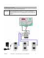
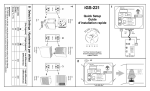
The iGS-221 allows the connection to an alarm system. See the Alarm section
on page 17 for more information.
I N S T A LL A T I O N A N D S E C U R I T Y N O T I C E
DANGER: To reduce risks of fire hazards or electrical shocks, attentively read
the following instructions before powering the system with electricity. THE
EQUIPMENT(S) PLUGGED TO THE IGS-25 OUTLETS AND CONTROLLED
BY THE IGS-221 MUST HAVE THEIR OWN OVERHEATING PROTECTION
BREAKER OR APPROPRIATE DEVICE
SAFE INSTALLATION OF THE IGS-25
All iGS-25 have to be plugged in a 120V-15 A outlet. Each iGS-25 can support a
maximal load of 15 A. In order to take advantage of 15 A for each iGS-25, it is
important to use 3 electrical outlets on 3 separate electrical circuits. The
equipments’ total load must not exceed the electrical circuit capacity.
SAFE INSTALLATION OF THE CONTROL AND THE CONNECTION MODULES
The control module must be fixed to a vertical wall with 4 screws. Locate the
control module at the plants’ height and at a representative location for the
conditions’ measurements. Also, the light sensor (photocell), located in the
bottom right corner, must be able to detect the presence or absence of light.
The connection module also must be fixed on a vertical wall with 2 screws. For a
long distance connection, it is possible to replace the cables linking the iGS-25
and the connection module with other Ethernet cables with a maximal length of
50 feet. However, it is not recommended to use a cable longer than the one
included between the control module and the connection module.
iGS-221
© 2010-2011 - Nova Biomatique inc. PLUG’N’GROW™
5