1
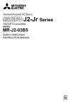
General-Purpose AC Servo
J2-Jr Series
General-Purpose Interface Compatible
MODEL
MR-J2-03A5
SERVO AMPLIFIER
INSTRUCTION MANUAL
C
z Safety Instructions z
(Always read these instructions before using the equipment.)
Do not attempt to install, operate, maintain or inspect the servo amplifier and servo motor until you have read
through this Instruction Manual, Installation guide, Servo motor Instruction Manual and appended documents
carefully and can use the equipment correctly. Do not use the servo amplifier and servo motor until you have a
full knowledge of the equipment, safety information and instructions.
In this Instruction Manual, the safety instruction levels are classified into "WARNING" and "CAUTION".
WARNING
Indicates that incorrect handling may cause hazardous conditions,,
resulting in death or severe injury.
CAUTION
Indicates that incorrect handling may cause hazardous conditions,,
resulting in medium or slight injury to personnel or may cause physical
damage.
Note that the CAUTION level may lead to a serious consequence according to conditions. Please follow the
instructions of both levels because they are important to personnel safety.
What must not be done and what must be done are indicated by the following diagrammatic symbols:
: Indicates what must not be done. For example, "No Fire" is indicated by .
: Indicates what must be done. For example, grounding is indicated by .
In this Instruction Manual, instructions at a lower level than the above, instructions for other functions, and so
on are classified into "POINT".
After reading this installation guide, always keep it accessible to the operator.
A- 1
1. To prevent electric shock, note the following:
WARNING
y Before wiring or inspection, switch power off and wait for more than 15 minutes. Then, confirm the voltage is
safe with voltage tester. Otherwise, you may get an electric shock.
y Connect the servo amplifier and servo motor to ground.
y Any person who is involved in wiring and inspection should be fully competent to do the work.
y Do not attempt to wire the servo amplifier and servo motor until they have been installed. Otherwise, you
may get an electric shock.
y Operate the switches with dry hand to prevent an electric shock.
y The cables should not be damaged, stressed loaded,, or pinched. Otherwise, you may get an electric
shock.
2. To prevent fire, note the following:
CAUTION
y Do not install the servo amplifier, servo motor and regenerative brake resistor on or near combustibles.
Otherwise a fire may cause.
y When the servo amplifier has become faulty, switch off the main servo amplifier power side. Continuous
flow of a large current may cause a fire.
3. To prevent injury, note the follow
CAUTION
y Only the voltage specified in the Instruction Manual should be applied to each terminal,, Otherwise,, a burst,,
damage,, etc. may occur.
y Connect the terminals correctly to prevent a burst,, damage,, etc.
y Ensure that polarity (+, −) is correct. Otherwise, a burst, damage, etc. may occur.
y Take safety measures, e.g. provide covers, to prevent accidental contact of hands and parts (cables, etc.)
with the servo amplifier heat sink, regenerative brake resistor, servo motor, etc.since they may be hot while
power is on or for some time after power-off. Their temperatures may be high and you may get burnt or a
parts may damaged.
y During operation, never touch the rotating parts of the servo motor. Doing so can cause injury.
A- 2
4. Additional instructions
The following instructions should also be fully noted. Incorrect handling may cause a fault, injury, electric shock,
etc.
(1) Transportation and installation
CAUTION
y Transport the products correctly according to their masses.
y Stacking in excess of the specified number of products is not allowed.
y Do not carry the servo motor by the cables, shaft or encoder.
y Do not hold the front cover to transport the servo amplifier. The servo amplifier may drop.
y Install the servo amplifier in a load-bearing place in accordance with the Instruction Manual.
y Do not climb or stand on servo equipment. Do not put heavy objects on equipment.
y The servo amplifier and servo motor must be installed in the specified direction.
y Leave specified clearances between the servo amplifier and control enclosure walls or other equipment.
y Do not install or operate the servo amplifier and servo motor which has been damaged or has any parts
missing.
y Provide adequate protection to prevent screws and other conductive matter, oil and other combustible
matter from entering the servo amplifier.
y Do not drop or strike servo amplifier or servo motor. Isolate from all impact loads.
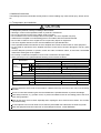
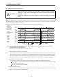
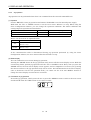
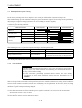
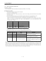
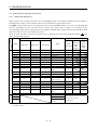
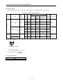
y When you keep or use it, please fulfill the following environmental conditions.
Conditions
Environment
Ambient
temperature
Ambient
humidity
During
operation
In storage
Servo Amplifier
[ ]
0 to
[ ]
32 to 131 (non-freezing)
[ ]
[ ]
In operation
Servo Motor
0 to
40 (non-freezing)
32 to 104 (non-freezing)
20 to 65 (non-freezing)
15 to 70 (non-freezing)
4 to 149 (non-freezing)
90%RH or less (non-condensing)
5 to 158 (non-freezing)
80%RH or less (non-condensing)
90%RH or less (non-condensing)
In storage
Ambience
Indoors (no direct sunlight) Free from corrosive gas, flammable gas, oil mist, dust and dirt
Altitude
(Note)
Vibration
55 (non-freezing)
Max. 1000m (3280 ft) above sea level
2
[m/s ] 5.9 or less
HC-AQ Series
X x Y : 19.6
[ft/s2]
HC-AQ Series
X x Y : 64
19.4 or less
Note. Except the servo motor with reduction gear.
Securely attach the servo motor to the machine. If attach insecurely, the servo motor may come off during
operation.
The servo motor with reduction gear must be installed in the specified direction to prevent oil leakage.
Take safety measures, e.g. provide covers, to prevent accidental access to the rotating parts of the servo
motor during operation.
Never hit the servo motor or shaft, especially when coupling the servo motor to the machine. The encoder
may become faulty.
Do not subject the servo motor shaft to more than the permissible load. Otherwise, the shaft may break.
When the equipment has been stored for an extended period of time, consult Mitsubishi.
A- 3
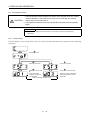
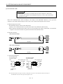
(2) Wiring
CAUTION
y Wire the equipment correctly and securely. Otherwise, the servo motor may misoperate.
y Do not install a power capacitor, surge absorber or radio noise filter between the servo motor and servo
amplifier.
y Connect the output terminals (U, V, W) correctly. Otherwise, the servo motor will operate improperly.
y Do not connect AC power directly to the servo motor. Otherwise, a fault may occur.
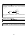
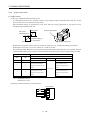
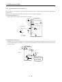
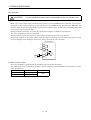
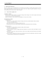
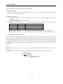
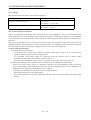
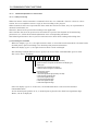
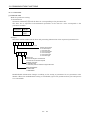
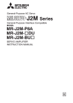
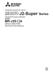
y The surge absorbing diode installed on the DC output signal relay must be wired in the specified direction.
Otherwise, the emergency stop and other protective circuits may not operate.
Servo
Amplifier
Servo
Amplifier
COM
(24VDC)
Control
output
signal
COM
(24VDC)
Control
output
signal
RA
RA
(3) Test run adjustment
CAUTION
y Before operation, check the parameter settings. Improper settings may cause some machines to perform
unexpected operation.
y The parameter settings must not be changed excessively. Operation will be instable.
(4) Usage
CAUTION
y Provide an external emergency stop circuit to ensure that operation can be stopped and power switched off
immediately.
y Any person who is involved in disassembly and repair should be fully competent to do the work.
y Before resetting an alarm, make sure that the run signal is off to prevent an accident. A sudden restart is
made if an alarm is reset with the run signal on.
y Do not modify the equipment.
y Use a noise filter, etc. to minimize the influence of electromagnetic interference, which may be caused by
electronic equipment used near the servo amplifier.
y Use the servo amplifier with the specified servo motor.
y The electromagnetic brake on the servo motor is designed to hold the servo motor shaft and should not be
used for ordinary braking.
y For such reasons as service life and mechanical structure (e.g. where a ballscrew and the servo motor are
coupled via a timing belt), the electromagnetic brake may not hold the servo motor shaft. To ensure safety,
install a stopper on the machine side.
A- 4
(5) Corrective actions
CAUTION
y When it is assumed that a hazardous condition may take place at the occur due to a power failure or a
product fault, use a servo motor with electromagnetic brake or an external brake mechanism for the
purpose of prevention.
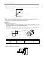
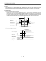
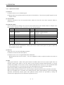
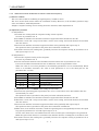
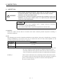
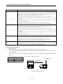
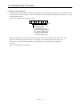
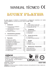
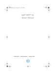
y Configure the electromagnetic brake circuit so that it is activated not only by the servo amplifier signals but
also by an emergency stop.
EMG
Servo amplifier
Circuit must be
opened during
emergency stop.
Servo motor
CNP2
y When any alarm has occurred, eliminate its cause, ensure safety, and deactivate the alarm before
restarting operation.
y When power is restored after an instantaneous power failure, keep away from the machine because the
machine may be restarted suddenly (design the machine so that it is secured against hazard if restarted).
(6) Maintenance, inspection and parts replacement
CAUTION
y With age, the electrolytic capacitor will deteriorate. To prevent a secondary accident due to a fault, it is
recommended to replace the electrolytic capacitor every 10 years when used in general environment.
(7) General instruction
y To illustrate details, the equipment in the diagrams of this Instruction Manual may have been drawn without
covers and safety guards. When the equipment is operated, the covers and safety guards must be installed
as specified. Operation must be performed in accordance with this Instruction Manual.
A- 5
About processing of waste
When you discard servo amplifier, a battery (primary battery), and other option articles, please follow the law of
each country (area).
FOR MAXIMUM SAFETY
These products have been manufactured as a general-purpose part for general industries, and have not
been designed or manufactured to be incorporated in a device or system used in purposes related to
human life.
Before using the products for special purposes such as nuclear power, electric power, aerospace, medicine,
passenger movement vehicles or under water relays, contact Mitsubishi.
These products have been manufactured under strict quality control. However, when installing the product
where major accidents or losses could occur if the product fails, install appropriate backup or failsafe
functions in the system.
EEP-ROM life
The number of write times to the EEP-ROM, which stores parameter settings, etc., is limited to 100,000. If the
total number of the following operations exceeds 100,000, the servo amplifier and/or converter unit may fail
when the EEP-ROM reaches the end of its useful life.
Write to the EEP-ROM due to parameter setting changes
Home position setting in the absolute position detection system
Precautions for Choosing the Products
Mitsubishi will not be held liable for damage caused by factors found not to be the cause of Mitsubishi;
machine damage or lost profits caused by faults in the Mitsubishi products; damage, secondary damage,
accident compensation caused by special factors unpredictable by Mitsubishi; damages to products other
than Mitsubishi products; and to other duties.
A- 6
COMPLIANCE WITH EC DIRECTIVES
1. WHAT ARE EC DIRECTIVES?
The EC directives were issued to standardize the regulations of the EU countries and ensure smooth
distribution of safety-guaranteed products. In the EU countries, the machinery directive (effective in
January, 1995), EMC directive (effective in January, 1996) and low voltage directive (effective in January,
1997) of the EC directives require that products to be sold should meet their fundamental safety
requirements and carry the CE marks (CE marking). CE marking applies to machines and equipment into
which servo amplifiers have been installed.
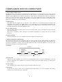
(1) EMC directive
The EMC directive applies not to the servo units alone but to servo-incorporated machines and
equipment. This requires the EMC filters to be used with the servo-incorporated machines and
equipment to comply with the EMC directive. For specific EMC directive conforming methods, refer to
the EMC Installation Guidelines (IB(NA)67310).
(2) Low voltage directive
The low voltage directive applies also to servo units alone. Hence, they are designed to comply with the
low voltage directive.
This servo is certified by TUV, third-party assessment organization, to comply with the low voltage
directive.
(3) Machine directive
Not being machines, the servo amplifiers need not comply with this directive.
2. PRECAUTIONS FOR COMPLIANCE
The standard models of the servo amplifier and servo motor comply with the EN Standard. In addition to
the instructions provided in this Instruction Manual, also follow the instructions below. If the model is not
specifically described to comply with the EN Standard in this Instruction Manual, it has the same
specifications as those of the standard models:
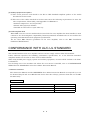
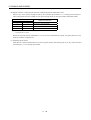
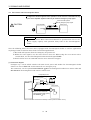
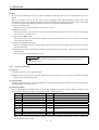
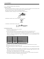
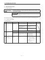
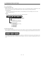
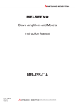
(1) Structure
Control box
Reinforced
insulation type
24VDC
power
supply
Circuit
protector
Servo
amplifier
Servo
motor
M
(2) Environment
Operate the servo amplifier at or above the contamination level 2 set forth in IEC60664-1. For this
purpose, install the servo amplifier in a control box which is protected against water, oil, carbon, dust,
dirt, etc. (IP54).
(3) Power supply
Use a 24VDC power supply which has been insulation-reinforced in I/O.
(4) Grounding
To prevent an electric shock, fit the supplied earth terminal (E) to the servo amplifier and always
connect it to the earth (E) of the control box.
A- 7
(5) Auxiliary equipment and options
(a) The circuit protector used should be the EN or IEC Standard-compliant product of the model
described in Section 12.2.2.
(b) The sizes of the cables described in Section 12.2.2 meet the following requirements. To meet the
other requirements, follow Table 5 and Appendix C in EN60204-1.
y Ambient temperature: 40 (104) [°C (°F)]
y Sheath: PVC (polyvinyl chloride)
y Installed on wall surface or open table tray
(6) Performing EMC tests
When EMC tests are run on a machine/device into which the servo amplifier has been installed, it must
conform to the electromagnetic compatibility (immunity/emission) standards after it has satisfied the
operating environment/electrical equipment specifications.
For the other EMC Directive guidelines on the servo amplifier, refer to the EMC Installation
Guidelines (IB(NA)67310).
CONFORMANCE WITH UL/C-UL STANDARD
The standard models of the servo amplifier and servo motor comply with the UL/C-UL Standard.
Unless otherwise specified, the handling, performance, specifications, etc. of the UL/C-UL Standardcompliant models are the same as those of the standard models.
When using 24VDC power supply, options and auxiliary equipment, use those which conform to the UL/CUL Standard.
For the flange size of the machine side where the servo motor is installed, refer to “CONFORMANCE
WITH UL/C-UL STANDARD” in the Servo Motor Instruction Manual.
<<About the manuals>>
This Instruction Manual and the MELSERVO Servo Motor Instruction Manual are required if you use
the General-Purpose AC servo MR-J2-03A5 for the first time. Always purchase them and use the MRJ2-03A5 safely.
Relevant manuals
Manual name
Manual No.
MELSERVO-J2-Jr. Series To Use the AC Servo Safely
IB(NA)67426
MELSERVO Servo Motor Instruction Manual
SH(NA)3181
EMC Installation Guidelines
IB(NA)67310
A- 8
CONTENTS
1. FUNCTIONS AND CONFIGURATION
1- 1 to 1- 6
1.1 Introduction ・・・・・・・・・・・・・・・・・・・・・・・・・・・・・・・・・・・・・・・・・・・・・・・・・・・・・・・・・・・・・・・・・・・・・・・・・・・
1.2 Servo Amplifier Standard Specifications ・・・・・・・・・・・・・・・・・・・・・・・・・・・・・・・・・・・・・・・・・・・・・・・・・・
1.3 Function List ・・・・・・・・・・・・・・・・・・・・・・・・・・・・・・・・・・・・・・・・・・・・・・・・・・・・・・・・・・・・・・・・・・・・・・・・・・
1.4 Model Code Definition ・・・・・・・・・・・・・・・・・・・・・・・・・・・・・・・・・・・・・・・・・・・・・・・・・・・・・・・・・・・・・・・・・・
1.5 Combination with Servo Motor ・・・・・・・・・・・・・・・・・・・・・・・・・・・・・・・・・・・・・・・・・・・・・・・・・・・・・・・・・・
1.6 Parts Identification ・・・・・・・・・・・・・・・・・・・・・・・・・・・・・・・・・・・・・・・・・・・・・・・・・・・・・・・・・・・・・・・・・・・・・
1.7 Servo System with Auxiliary Equipment・・・・・・・・・・・・・・・・・・・・・・・・・・・・・・・・・・・・・・・・・・・・・・・・・・
2. INSTALLATION
2- 1 to 2- 4
2.1 Environmental conditions ・・・・・・・・・・・・・・・・・・・・・・・・・・・・・・・・・・・・・・・・・・・・・・・・・・・・・・・・・・・・・・・
2.2 Installation direction and clearances ・・・・・・・・・・・・・・・・・・・・・・・・・・・・・・・・・・・・・・・・・・・・・・・・・・・・・
2.3 Keep out foreign materials ・・・・・・・・・・・・・・・・・・・・・・・・・・・・・・・・・・・・・・・・・・・・・・・・・・・・・・・・・・・・・・
2.4 Cable stress・・・・・・・・・・・・・・・・・・・・・・・・・・・・・・・・・・・・・・・・・・・・・・・・・・・・・・・・・・・・・・・・・・・・・・・・・・・・
2.5 Using the DIN rail for installation ・・・・・・・・・・・・・・・・・・・・・・・・・・・・・・・・・・・・・・・・・・・・・・・・・・・・・・・
3. SIGNALS AND WIRING
1- 1
1- 2
1- 3
1- 4
1- 4
1- 5
1- 6
2- 1
2- 2
2- 3
2- 3
2- 4
3- 1 to 3- 48
3.1 Standard connection example・・・・・・・・・・・・・・・・・・・・・・・・・・・・・・・・・・・・・・・・・・・・・・・・・・・・・・・・・・・・ 3- 2
3.1.1 Position control mode AD75P
(A1SD75P
) ・・・・・・・・・・・・・・・・・・・・・・・・・・・・・・・・・・・・・・・・・・ 3- 2
3.1.2 Speed control mode ・・・・・・・・・・・・・・・・・・・・・・・・・・・・・・・・・・・・・・・・・・・・・・・・・・・・・・・・・・・・・・・・・ 3- 4
3.1.3 Torque control mode ・・・・・・・・・・・・・・・・・・・・・・・・・・・・・・・・・・・・・・・・・・・・・・・・・・・・・・・・・・・・・・・・ 3- 5
3.2 Internal Connection Diagram of Servo Amplifier ・・・・・・・・・・・・・・・・・・・・・・・・・・・・・・・・・・・・・・・・・・ 3- 6
3.3 I/O Signals ・・・・・・・・・・・・・・・・・・・・・・・・・・・・・・・・・・・・・・・・・・・・・・・・・・・・・・・・・・・・・・・・・・・・・・・・・・・ 3- 7
3.3.1 Connectors and signal arrangements・・・・・・・・・・・・・・・・・・・・・・・・・・・・・・・・・・・・・・・・・・・・・・・・・・ 3- 7
3.3.2 Signal explanations ・・・・・・・・・・・・・・・・・・・・・・・・・・・・・・・・・・・・・・・・・・・・・・・・・・・・・・・・・・・・・・・・・ 3-10
3.4 Detailed Description of the Signals ・・・・・・・・・・・・・・・・・・・・・・・・・・・・・・・・・・・・・・・・・・・・・・・・・・・・・・・ 3-19
3.4.1 Position control mode・・・・・・・・・・・・・・・・・・・・・・・・・・・・・・・・・・・・・・・・・・・・・・・・・・・・・・・・・・・・・・・・ 3-19
3.4.2 Speed control mode ・・・・・・・・・・・・・・・・・・・・・・・・・・・・・・・・・・・・・・・・・・・・・・・・・・・・・・・・・・・・・・・・・ 3-24
3.4.3 Torque control mode ・・・・・・・・・・・・・・・・・・・・・・・・・・・・・・・・・・・・・・・・・・・・・・・・・・・・・・・・・・・・・・・・ 3-26
3.4.4 Position/speed control change mode ・・・・・・・・・・・・・・・・・・・・・・・・・・・・・・・・・・・・・・・・・・・・・・・・・・・ 3-29
3.4.5 Speed/torque control change mode ・・・・・・・・・・・・・・・・・・・・・・・・・・・・・・・・・・・・・・・・・・・・・・・・・・・・ 3-31
3.4.6 Torque/position control change mode・・・・・・・・・・・・・・・・・・・・・・・・・・・・・・・・・・・・・・・・・・・・・・・・・・ 3-33
3.5 Alarm Occurrence Timing Chart ・・・・・・・・・・・・・・・・・・・・・・・・・・・・・・・・・・・・・・・・・・・・・・・・・・・・・・・・・ 3-34
3.6 Interfaces ・・・・・・・・・・・・・・・・・・・・・・・・・・・・・・・・・・・・・・・・・・・・・・・・・・・・・・・・・・・・・・・・・・・・・・・・・・・・・ 3-35
3.6.1 Common line ・・・・・・・・・・・・・・・・・・・・・・・・・・・・・・・・・・・・・・・・・・・・・・・・・・・・・・・・・・・・・・・・・・・・・・・ 3-35
3.6.2 Detailed description of the interfaces・・・・・・・・・・・・・・・・・・・・・・・・・・・・・・・・・・・・・・・・・・・・・・・・・・ 3-36
3.7 Input Power Supply Circuit ・・・・・・・・・・・・・・・・・・・・・・・・・・・・・・・・・・・・・・・・・・・・・・・・・・・・・・・・・・・・・ 3-40
3.7.1 Connection example ・・・・・・・・・・・・・・・・・・・・・・・・・・・・・・・・・・・・・・・・・・・・・・・・・・・・・・・・・・・・・・・・・ 3-40
3.7.2 Explanation of signals ・・・・・・・・・・・・・・・・・・・・・・・・・・・・・・・・・・・・・・・・・・・・・・・・・・・・・・・・・・・・・・・ 3-41
3.7.3 Power-on sequence ・・・・・・・・・・・・・・・・・・・・・・・・・・・・・・・・・・・・・・・・・・・・・・・・・・・・・・・・・・・・・・・・・・ 3-41
3.8 Servo Motor with Electromagnetic Brake ・・・・・・・・・・・・・・・・・・・・・・・・・・・・・・・・・・・・・・・・・・・・・・・・・ 3-43
3.9 Grounding ・・・・・・・・・・・・・・・・・・・・・・・・・・・・・・・・・・・・・・・・・・・・・・・・・・・・・・・・・・・・・・・・・・・・・・・・・・・・・ 3-46
3.10 Instructions for the 3M Connector ・・・・・・・・・・・・・・・・・・・・・・・・・・・・・・・・・・・・・・・・・・・・・・・・・・・・・・ 3-47
4. OPERATION
4- 1 to 4- 6
4.1 When Switching Power On for the First Time ・・・・・・・・・・・・・・・・・・・・・・・・・・・・・・・・・・・・・・・・・・・・・
4.2 Startup・・・・・・・・・・・・・・・・・・・・・・・・・・・・・・・・・・・・・・・・・・・・・・・・・・・・・・・・・・・・・・・・・・・・・・・・・・・・・・・・
4.2.1 Selection of control mode ・・・・・・・・・・・・・・・・・・・・・・・・・・・・・・・・・・・・・・・・・・・・・・・・・・・・・・・・・・・・
4.2.2 Position control mode・・・・・・・・・・・・・・・・・・・・・・・・・・・・・・・・・・・・・・・・・・・・・・・・・・・・・・・・・・・・・・・・
4.2.3 Speed control mode ・・・・・・・・・・・・・・・・・・・・・・・・・・・・・・・・・・・・・・・・・・・・・・・・・・・・・・・・・・・・・・・・・
4.2.4 Torque control mode ・・・・・・・・・・・・・・・・・・・・・・・・・・・・・・・・・・・・・・・・・・・・・・・・・・・・・・・・・・・・・・・・
4.3 Multidrop Communication ・・・・・・・・・・・・・・・・・・・・・・・・・・・・・・・・・・・・・・・・・・・・・・・・・・・・・・・・・・・・・・
5. PARAMETERS
4- 1
4- 2
4- 2
4- 2
4- 4
4- 5
4- 6
5- 1 to 5- 22
5.1 Parameter List ・・・・・・・・・・・・・・・・・・・・・・・・・・・・・・・・・・・・・・・・・・・・・・・・・・・・・・・・・・・・・・・・・・・・・・・・・ 5- 1
5.1.1 Parameter write inhibit・・・・・・・・・・・・・・・・・・・・・・・・・・・・・・・・・・・・・・・・・・・・・・・・・・・・・・・・・・・・・・ 5- 1
5.1.2 Lists ・・・・・・・・・・・・・・・・・・・・・・・・・・・・・・・・・・・・・・・・・・・・・・・・・・・・・・・・・・・・・・・・・・・・・・・・・・・・・・・ 5- 2
5.2 Detailed Description ・・・・・・・・・・・・・・・・・・・・・・・・・・・・・・・・・・・・・・・・・・・・・・・・・・・・・・・・・・・・・・・・・・・ 5- 18
5.2.1 Electronic gear ・・・・・・・・・・・・・・・・・・・・・・・・・・・・・・・・・・・・・・・・・・・・・・・・・・・・・・・・・・・・・・・・・・・・ 5- 18
5.2.2 Changing the status display screen ・・・・・・・・・・・・・・・・・・・・・・・・・・・・・・・・・・・・・・・・・・・・・・・・・・ 5- 20
5.2.3 Using forward/reverse rotation stroke end to change the stopping pattern ・・・・・・・・・・・・・・・ 5- 21
5.2.4 Alarm history clear・・・・・・・・・・・・・・・・・・・・・・・・・・・・・・・・・・・・・・・・・・・・・・・・・・・・・・・・・・・・・・・・・ 5- 21
6. DISPLAY AND OPERATION
6- 1 to 6- 16
6.1 Display Flowchart ・・・・・・・・・・・・・・・・・・・・・・・・・・・・・・・・・・・・・・・・・・・・・・・・・・・・・・・・・・・・・・・・・・・・・・ 6- 1
6.2 Status Display ・・・・・・・・・・・・・・・・・・・・・・・・・・・・・・・・・・・・・・・・・・・・・・・・・・・・・・・・・・・・・・・・・・・・・・・・・ 6- 2
6.3 Diagnostic mode・・・・・・・・・・・・・・・・・・・・・・・・・・・・・・・・・・・・・・・・・・・・・・・・・・・・・・・・・・・・・・・・・・・・・・・・ 6- 4
6.4 Alarm mode ・・・・・・・・・・・・・・・・・・・・・・・・・・・・・・・・・・・・・・・・・・・・・・・・・・・・・・・・・・・・・・・・・・・・・・・・・・・ 6- 5
6.5 Parameter mode ・・・・・・・・・・・・・・・・・・・・・・・・・・・・・・・・・・・・・・・・・・・・・・・・・・・・・・・・・・・・・・・・・・・・・・・ 6- 6
6.6 External I/O signal display ・・・・・・・・・・・・・・・・・・・・・・・・・・・・・・・・・・・・・・・・・・・・・・・・・・・・・・・・・・・・・・ 6- 8
6.7 Output signal forced output (DO forced output)・・・・・・・・・・・・・・・・・・・・・・・・・・・・・・・・・・・・・・・・・・・ 6- 11
6.8 Test operation mode ・・・・・・・・・・・・・・・・・・・・・・・・・・・・・・・・・・・・・・・・・・・・・・・・・・・・・・・・・・・・・・・・・・・ 6- 12
6.8.1 Mode change ・・・・・・・・・・・・・・・・・・・・・・・・・・・・・・・・・・・・・・・・・・・・・・・・・・・・・・・・・・・・・・・・・・・・・・ 6- 12
6.8.2 Jog operation ・・・・・・・・・・・・・・・・・・・・・・・・・・・・・・・・・・・・・・・・・・・・・・・・・・・・・・・・・・・・・・・・・・・・・・ 6- 13
6.8.3 Positioning operation ・・・・・・・・・・・・・・・・・・・・・・・・・・・・・・・・・・・・・・・・・・・・・・・・・・・・・・・・・・・・・・・ 6- 14
6.8.4 Motor-less operation ・・・・・・・・・・・・・・・・・・・・・・・・・・・・・・・・・・・・・・・・・・・・・・・・・・・・・・・・・・・・・・・ 6- 15
7. ADJUSTMENT
7- 1 to 7- 10
7.1 What Is Gain Adjustment? ・・・・・・・・・・・・・・・・・・・・・・・・・・・・・・・・・・・・・・・・・・・・・・・・・・・・・・・・・・・・・・
7.1.1 Difference between servo amplifier and other drives ・・・・・・・・・・・・・・・・・・・・・・・・・・・・・・・・・・・・
7.1.2 Basics of the servo system ・・・・・・・・・・・・・・・・・・・・・・・・・・・・・・・・・・・・・・・・・・・・・・・・・・・・・・・・・・・
7.2 Gain Adjustment ・・・・・・・・・・・・・・・・・・・・・・・・・・・・・・・・・・・・・・・・・・・・・・・・・・・・・・・・・・・・・・・・・・・・・・・
7.2.1 Parameters required for gain adjustment・・・・・・・・・・・・・・・・・・・・・・・・・・・・・・・・・・・・・・・・・・・・・・
7.2.2 Block diagram ・・・・・・・・・・・・・・・・・・・・・・・・・・・・・・・・・・・・・・・・・・・・・・・・・・・・・・・・・・・・・・・・・・・・・・
7.2.3 What is auto tuning? ・・・・・・・・・・・・・・・・・・・・・・・・・・・・・・・・・・・・・・・・・・・・・・・・・・・・・・・・・・・・・・・・
7- 1
7- 1
7- 2
7- 3
7- 3
7- 3
7- 4
7.3 Gain Adjustment by Auto Tuning ・・・・・・・・・・・・・・・・・・・・・・・・・・・・・・・・・・・・・・・・・・・・・・・・・・・・・・・・ 7- 5
7.3.1 Adjustment method ・・・・・・・・・・・・・・・・・・・・・・・・・・・・・・・・・・・・・・・・・・・・・・・・・・・・・・・・・・・・・・・・・ 7- 5
7.3.2 Valid conditions・・・・・・・・・・・・・・・・・・・・・・・・・・・・・・・・・・・・・・・・・・・・・・・・・・・・・・・・・・・・・・・・・・・・・ 7- 5
7.4 Manual Gain Adjustment ・・・・・・・・・・・・・・・・・・・・・・・・・・・・・・・・・・・・・・・・・・・・・・・・・・・・・・・・・・・・・・・ 7- 6
7.4.1 When machine rigidity is low・・・・・・・・・・・・・・・・・・・・・・・・・・・・・・・・・・・・・・・・・・・・・・・・・・・・・・・・・ 7- 6
7.4.2 When the machine vibrates due to machine resonance frequency ・・・・・・・・・・・・・・・・・・・・・・・・ 7- 7
7.4.3 Load inertia moment is 20 or more times ・・・・・・・・・・・・・・・・・・・・・・・・・・・・・・・・・・・・・・・・・・・・・・ 7- 8
7.4.4 When shortening the settling time ・・・・・・・・・・・・・・・・・・・・・・・・・・・・・・・・・・・・・・・・・・・・・・・・・・・・ 7- 9
7.4.5 When the same gain is used for two or more axes・・・・・・・・・・・・・・・・・・・・・・・・・・・・・・・・・・・・・・ 7- 10
7.5 Slight Vibration Suppression Control・・・・・・・・・・・・・・・・・・・・・・・・・・・・・・・・・・・・・・・・・・・・・・・・・・・・ 7- 10
8. INSPECTION
9. TROUBLESHOOTING
8- 1 to 8- 2
9- 1 to 9- 12
9.1 Trouble at Start-Up ・・・・・・・・・・・・・・・・・・・・・・・・・・・・・・・・・・・・・・・・・・・・・・・・・・・・・・・・・・・・・・・・・・・・ 9- 1
9.1.1 Position control mode・・・・・・・・・・・・・・・・・・・・・・・・・・・・・・・・・・・・・・・・・・・・・・・・・・・・・・・・・・・・・・・・ 9- 1
9.1.2 Speed control mode ・・・・・・・・・・・・・・・・・・・・・・・・・・・・・・・・・・・・・・・・・・・・・・・・・・・・・・・・・・・・・・・・・ 9- 4
9.1.3 Torque control mode ・・・・・・・・・・・・・・・・・・・・・・・・・・・・・・・・・・・・・・・・・・・・・・・・・・・・・・・・・・・・・・・・ 9- 5
9.2 When Alarm or Warning Has Occurred ・・・・・・・・・・・・・・・・・・・・・・・・・・・・・・・・・・・・・・・・・・・・・・・・・・・ 9- 6
9.2.1 Alarms and Warning list・・・・・・・・・・・・・・・・・・・・・・・・・・・・・・・・・・・・・・・・・・・・・・・・・・・・・・・・・・・・・ 9- 6
9.2.2 Remedies for alarms ・・・・・・・・・・・・・・・・・・・・・・・・・・・・・・・・・・・・・・・・・・・・・・・・・・・・・・・・・・・・・・・・ 9- 7
9.2.3 Remedies for Warnings ・・・・・・・・・・・・・・・・・・・・・・・・・・・・・・・・・・・・・・・・・・・・・・・・・・・・・・・・・・・・・ 9- 11
10. OUTLINE DIMENSION DRAWINGS
10- 1 to 10- 4
10.1 Servo amplifiers・・・・・・・・・・・・・・・・・・・・・・・・・・・・・・・・・・・・・・・・・・・・・・・・・・・・・・・・・・・・・・・・・・・・・・ 10- 1
10.2 Connectors ・・・・・・・・・・・・・・・・・・・・・・・・・・・・・・・・・・・・・・・・・・・・・・・・・・・・・・・・・・・・・・・・・・・・・・・・・・ 10- 2
11. CHARACTERISTICS
11- 1 to 11- 4
11.1 Overload Protection Characteristics ・・・・・・・・・・・・・・・・・・・・・・・・・・・・・・・・・・・・・・・・・・・・・・・・・・・・ 11- 1
11.2 Dynamic Brake Characteristics ・・・・・・・・・・・・・・・・・・・・・・・・・・・・・・・・・・・・・・・・・・・・・・・・・・・・・・・・ 11- 2
11.3 Encoder Cable Flexing Life・・・・・・・・・・・・・・・・・・・・・・・・・・・・・・・・・・・・・・・・・・・・・・・・・・・・・・・・・・・・ 11- 3
12. OPTIONS AND AUXILIARY EQUIPMENT
12- 1 to 12- 18
12.1 Options ・・・・・・・・・・・・・・・・・・・・・・・・・・・・・・・・・・・・・・・・・・・・・・・・・・・・・・・・・・・・・・・・・・・・・・・・・・・・・ 12- 1
12.1.1 Cables and connectors ・・・・・・・・・・・・・・・・・・・・・・・・・・・・・・・・・・・・・・・・・・・・・・・・・・・・・・・・・・・・・ 12- 1
12.1.2 Junction terminal block (MR-TB20)・・・・・・・・・・・・・・・・・・・・・・・・・・・・・・・・・・・・・・・・・・・・・・・・・ 12- 7
12.1.3 Servo configurations software ・・・・・・・・・・・・・・・・・・・・・・・・・・・・・・・・・・・・・・・・・・・・・・・・・・・・・・ 12- 9
12.2 Auxiliary Equipment ・・・・・・・・・・・・・・・・・・・・・・・・・・・・・・・・・・・・・・・・・・・・・・・・・・・・・・・・・・・・・・・・ 12- 11
12.2.1 Recommended wires ・・・・・・・・・・・・・・・・・・・・・・・・・・・・・・・・・・・・・・・・・・・・・・・・・・・・・・・・・・・・・ 12- 11
12.2.2 Circuit protector ・・・・・・・・・・・・・・・・・・・・・・・・・・・・・・・・・・・・・・・・・・・・・・・・・・・・・・・・・・・・・・・・・ 12- 12
12.2.3 Relays ・・・・・・・・・・・・・・・・・・・・・・・・・・・・・・・・・・・・・・・・・・・・・・・・・・・・・・・・・・・・・・・・・・・・・・・・・・ 12- 13
12.2.4 Noise reduction techniques ・・・・・・・・・・・・・・・・・・・・・・・・・・・・・・・・・・・・・・・・・・・・・・・・・・・・・・・ 12- 13
12.2.5 Snubber unit ・・・・・・・・・・・・・・・・・・・・・・・・・・・・・・・・・・・・・・・・・・・・・・・・・・・・・・・・・・・・・・・・・・・・ 12- 17
13. COMMUNICATION FUNCTIONS
13- 1 to 13- 26
13.1 Configuration ・・・・・・・・・・・・・・・・・・・・・・・・・・・・・・・・・・・・・・・・・・・・・・・・・・・・・・・・・・・・・・・・・・・・・・・・ 13- 1
13.1.1 RS-422 configuration ・・・・・・・・・・・・・・・・・・・・・・・・・・・・・・・・・・・・・・・・・・・・・・・・・・・・・・・・・・・・・・ 13- 1
13.1.2 RS-232C configuration ・・・・・・・・・・・・・・・・・・・・・・・・・・・・・・・・・・・・・・・・・・・・・・・・・・・・・・・・・・・・ 13- 2
13.2 Communication Specifications ・・・・・・・・・・・・・・・・・・・・・・・・・・・・・・・・・・・・・・・・・・・・・・・・・・・・・・・・・ 13- 3
13.2.1 Communication overview ・・・・・・・・・・・・・・・・・・・・・・・・・・・・・・・・・・・・・・・・・・・・・・・・・・・・・・・・・・ 13- 3
13.2.2 Parameter setting・・・・・・・・・・・・・・・・・・・・・・・・・・・・・・・・・・・・・・・・・・・・・・・・・・・・・・・・・・・・・・・・・ 13- 4
13.3 Protocol ・・・・・・・・・・・・・・・・・・・・・・・・・・・・・・・・・・・・・・・・・・・・・・・・・・・・・・・・・・・・・・・・・・・・・・・・・・・・・ 13- 5
13.4 Character Codes ・・・・・・・・・・・・・・・・・・・・・・・・・・・・・・・・・・・・・・・・・・・・・・・・・・・・・・・・・・・・・・・・・・・・・ 13- 6
13.5 Error Codes ・・・・・・・・・・・・・・・・・・・・・・・・・・・・・・・・・・・・・・・・・・・・・・・・・・・・・・・・・・・・・・・・・・・・・・・・・ 13- 7
13.6 Checksum ・・・・・・・・・・・・・・・・・・・・・・・・・・・・・・・・・・・・・・・・・・・・・・・・・・・・・・・・・・・・・・・・・・・・・・・・・・・ 13- 7
13.7 Time-Out Operation ・・・・・・・・・・・・・・・・・・・・・・・・・・・・・・・・・・・・・・・・・・・・・・・・・・・・・・・・・・・・・・・・・・ 13- 8
13.8 Retry Operation・・・・・・・・・・・・・・・・・・・・・・・・・・・・・・・・・・・・・・・・・・・・・・・・・・・・・・・・・・・・・・・・・・・・・・ 13- 8
13.9 Initialization・・・・・・・・・・・・・・・・・・・・・・・・・・・・・・・・・・・・・・・・・・・・・・・・・・・・・・・・・・・・・・・・・・・・・・・・・ 13- 9
13.10 Communication Procedure Example ・・・・・・・・・・・・・・・・・・・・・・・・・・・・・・・・・・・・・・・・・・・・・・・・・・ 13- 9
13.11 Command and Data No. List ・・・・・・・・・・・・・・・・・・・・・・・・・・・・・・・・・・・・・・・・・・・・・・・・・・・・・・・・ 13- 10
13.11.1 Read commands ・・・・・・・・・・・・・・・・・・・・・・・・・・・・・・・・・・・・・・・・・・・・・・・・・・・・・・・・・・・・・・・・ 13- 10
13.11.2 Write commands・・・・・・・・・・・・・・・・・・・・・・・・・・・・・・・・・・・・・・・・・・・・・・・・・・・・・・・・・・・・・・・・ 13- 11
13.12 Detailed Explanations of Commands ・・・・・・・・・・・・・・・・・・・・・・・・・・・・・・・・・・・・・・・・・・・・・・・・・ 13- 13
13.12.1 Data processing ・・・・・・・・・・・・・・・・・・・・・・・・・・・・・・・・・・・・・・・・・・・・・・・・・・・・・・・・・・・・・・・・ 13- 13
13.12.2 Status display ・・・・・・・・・・・・・・・・・・・・・・・・・・・・・・・・・・・・・・・・・・・・・・・・・・・・・・・・・・・・・・・・・・ 13- 15
13.12.3 Parameter ・・・・・・・・・・・・・・・・・・・・・・・・・・・・・・・・・・・・・・・・・・・・・・・・・・・・・・・・・・・・・・・・・・・・・ 13- 16
13.12.4 External I/O pin statuses (DIO diagnosis) ・・・・・・・・・・・・・・・・・・・・・・・・・・・・・・・・・・・・・・・・・ 13- 18
13.12.5 Disable/enable of external I/O signals (DIO) ・・・・・・・・・・・・・・・・・・・・・・・・・・・・・・・・・・・・・・・ 13- 19
13.12.6 External input signal ON/OFF (Test operation) ・・・・・・・・・・・・・・・・・・・・・・・・・・・・・・・・・・・・ 13- 20
13.12.7 Test operation mode ・・・・・・・・・・・・・・・・・・・・・・・・・・・・・・・・・・・・・・・・・・・・・・・・・・・・・・・・・・・・ 13- 21
13.12.8 Output signal pin ON/OFF (DO forced output)・・・・・・・・・・・・・・・・・・・・・・・・・・・・・・・・・・・・・ 13- 23
13.12.9 Alarm history ・・・・・・・・・・・・・・・・・・・・・・・・・・・・・・・・・・・・・・・・・・・・・・・・・・・・・・・・・・・・・・・・・・ 13- 24
13.12.10 Current alarm・・・・・・・・・・・・・・・・・・・・・・・・・・・・・・・・・・・・・・・・・・・・・・・・・・・・・・・・・・・・・・・・・ 13- 25
13.12.11 Other commands ・・・・・・・・・・・・・・・・・・・・・・・・・・・・・・・・・・・・・・・・・・・・・・・・・・・・・・・・・・・・・・ 13- 26
Optional Servo Motor Instruction Manual CONTENTS
The rough table of contents of the optional MELSERVO Servo Motor Instruction Manual is introduced
here for your reference. Note that the contents of the Servo Motor Instruction Manual are not included
in the Servo Amplifier Instruction Manual.
1. INTRODUCTION
2. INSTALLATION
3. CONNECTORS USED FOR SERVO MOTOR WIRING
4. INSPECTION
5. SPECIFICATIONS
6. CHARACTERISTICS
7. OUTLINE DIMENSION DRAWINGS
8. CALCULATION METHODS FOR DESIGNING
MEMO
1. FUNCTIONS AND CONFIGURATION
1. FUNCTIONS AND CONFIGURATION
1.1 Introduction
The MELSERVO-J2-Jr series general-purpose AC servo has been developed as an ultracompact, small
capacity servo system compatible with the MELSERVO-J2 series 24VDC power supply. It can be used in a
wide range of fields from semiconductor equipment to small robots, etc.
The input signals of the servo amplifier control system are compatible with those of the MR-J2-A.
As the standard models comply with the EN Standard x UL/C-UL Standard, they can be used satisfactorily
in various countries.
The MR-J2-03A5 servo amplifier can be easily installed to a control box with a DIN rail.
The power supply/electromagnetic brake and encoder of the servo motor can be wired easily with a single
cable.
Using a personal computer where the Servo Configuration software has been installed, you can make
parameter setting, status display, etc.
Also, you can use the RS-422 communication function to set up to 32 axes of servo amplifiers.
The compatible servo motors have achieved the smallest 28mm-bore flange size in this class and are
further equipped with encoders of 8192 pulses/rev (incremental) resolution.
1- 1
1. FUNCTIONS AND CONFIGURATION
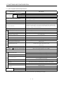
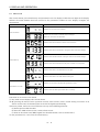
1.2 Servo Amplifier Standard Specifications
Servo Amplifier
MR-J2-03A5
Item
Voltage
Circuit power
supply
Power
supply
capacity
HC-AQ0135D
HC-AQ0235D
HC-AQ0335D
Control circuit power supply (Note)
Control system
21.6 to 30VDC (instantaneous permissible voltage 34V)
Continuous 0.8A, max. 2.4A
Continuous 1.6A, max. 4.8A
Continuous 2.4A, max. 7.2A
24VDC±10%, 200mA (400mA when using the servo motor equipped with
electromagnetic brake)
Sine-wave PWM control, current control system
Dynamic brake
Built-in
Overcurrent shut-off, regenerative overvoltage shut-off, overload shut-off
(electronic thermal relay), servo motor overheat protection, encoder fault
protection, undervoltage, instantaneous power failure protection, overspeed
protection, excessive error protection
Protective functions
Position control mode
Max. input pulse frequency
Speed control mode
Speed frequency response
Speed control range
250Hz or more
500kpps (for differential receiver), 200kpps (for open collector)
Command pulse multiplying factor
Electronic gear A/B, A, B: 1 to 32767, 1/50 < A/B < 50
0 to ±10000 pulse
In-position range setting
±80 kpulse
Error excessive
Torque limit
Parameter setting system
Analog speed command 1: 1000, internal speed command 1: 5000
DC0 to ±10V
Analog speed command input
−0.03% or less (load fluctuation 0 to 100%)
±0.02% or less (power fluctuation ±10%)
±3% or less
Speed fluctuation ratio
Torque limit
Parameter setting system
Torque control
Analog torque command input
mode
DC0 to ±8V (input impedance 10 to 12kΩ)
Structure
Open (IP00)
0 to +55 [°C] (non-freezing)
Ambient temperature
32 to +131 [°F] (non-freezing)
Environment
Ambient humidity
90%RH or less (non-condensing)
−20 to +65 [°C] (non-freezing)
storage temperature
−4 to +149 [°F] (non-freezing)
storage humidity
90%RH or less (non-condensing)
Ambient
Indoors (no direct sunlight)
Free from corrosive gas, flammable gas, oil mist, dust and dirt
Altitude
Max. 1000m (3280ft) above sea level
5.9 [m/s2] or less
Vibration
Mass
19.4 [ft/s2] or less
[kg]
0.2
[lb]
0.44
Note. To comply with the Low Voltage Directive, use a reinforced insulation type stabilizing power supply.
1- 2
1. FUNCTIONS AND CONFIGURATION
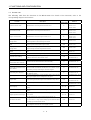
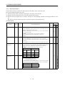
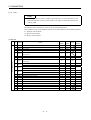
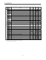
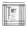
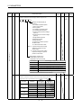
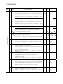
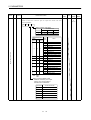
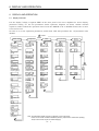
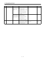
1.3 Function List
The following table lists the functions of the MR-J2-03A5. For details of the functions, refer to the
corresponding chapters and sections.
Function
Description
(Note)
Control Mode
Refer To
Position control mode
MR-J2-03A5 is used as position control servo.
P
Section 3.1.1
Section 3.4.1
Section 4.2.2
Speed control mode
MR-J2-03A5 is used as speed control servo.
S
Section 3.1.2
Section 3.4.2
Section 4.2.3
Torque control mode
MR-J2-03A5 is used as torque control servo.
T
Section 3.1.3
Section 3.4.3
Section 4.2.4
Position/speed control
change mode
Using external input signal, control can be switched
between position control and speed control.
P/S
Section 3.4.4
Speed/torque control change Using external input signal, control can be switched
mode
between speed control and torque control.
S/T
Section 3.4.5
Torque/position control
change mode
T/P
Section 3.4.6
Using external input signal, control can be switched
between torque control and position control.
Slight vibration suppression Suppresses vibration of ±1 pulse produced at a servo motor
control
stop.
P
Section 7.5
Electronic gear
Input pulses can be multiplied by 1/50 to 50.
P
Parameters No. 3, 4
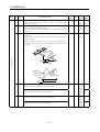
Real-time auto tuning
Automatically adjusts the gain to optimum value if load
applied to the servo motor shaft varies.
P, S
Section 7.3
Parameter No. 2
Smoothing
Speed can be increased smoothly in response to input pulse.
P
Parameter No. 7
S-pattern acceleration/
deceleration time constant
Speed can be increased and decreased smoothly.
S
Parameter No. 13
Alarm history clear
Alarm history is cleared.
P, S, T
Parameter No. 16
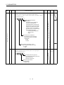
Restart after instantaneous
power failure
If the input power supply voltage had reduced to cause an
alarm but has returned to normal, the servo motor can be
restarted by merely switching on the start signal.
S
Parameter No. 20
Command pulse selection
Command pulse train form can be selected from among
four different types.
P
Parameter No. 21
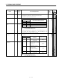
Input signal selection
Forward rotation start, reverse rotation start, servo on and
other input signals can be assigned to any pins.
P, S, T
Torque limit
Servo motor-generated torque can be limited to any value.
P, S
Speed limit
Servo motor speed can be limited to any value.
Status display
Servo status is shown on the 4-digit, 7-segment LED
display
P, S, T
Section 6.2
External I/O display
ON/OFF statuses of external I/O signals are shown on the
display.
P, S, T
Section 6.6
Output signal can be forced on/off independently of the
Output signal forced output servo status.
Use this function for output signal wiring check, etc.
P, S, T
Section 6.7
T
Parameters No. 43 to
48
Section 3.4.1 (2)
Parameter No. 28
Section 3.4.3 (3)
Parameter No. 8 to 10
Automatic VC offset
Voltage is automatically offset to stop the servo motor if it
does not come to a stop at the analog speed command (VC)
or analog speed limit (VLA) of 0V.
S, T
Section 6.3
Test operation mode
Servo motor can be run from the operation section of the
servo amplifier without the start signal entered.
P, S, T
Section 6.8
1- 3
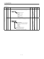
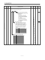
1. FUNCTIONS AND CONFIGURATION
Description
(Note)
Control Mode
Servo configuration
software
Using a personal computer, parameter setting, test
operation, status display, etc. can be performed.
P, S, T
Section 12.1.3
Alarm code output
If an alarm has occurred, the corresponding alarm number
is output in 3-bit code.
P, S, T
Section 9.2.1
Function
Refer To
Note. P: Position control mode, S: Speed control mode, T: Torque control mode
P/S: Position/speed control change mode, S/T: Speed/torque control change mode, T/P: Torque/position control change mode
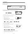
1.4 Model Code Definition
(1) Rating plate
MITSUBISHI
AC
SERVO
AC SERVO
MODEL MR-J2-03A5
Model
Capacity
POWER : 30W
POWER
INPUT : DC24V
Applicable power supply
OUTPUT : 2.3A
SERIAL : A5**********
TC3**AAAAG52
Rated output current
PASSED
Serial number
MITSUBISHI ELECTRIC CORPORATION
MADE IN JAPAN
(2) Model
MR-J2
- 03 A 5
Series name
Rating plate
24VDC power supply specification
General-purpose interface
Rated output 30[W]
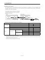
1.5 Combination with Servo Motor
The HC-AQ series servo motors can be used. The same combinations apply to the servo motors provided
with electromagnetic brakes and reduction gears.
Servo Amplifier
MR-J2-03A5
Servo motor
HC-AQ0135D
HC-AQ0235D
HC-AQ0335D
1- 4
1. FUNCTIONS AND CONFIGURATION
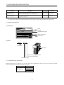
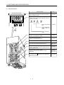
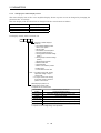
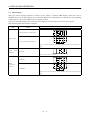
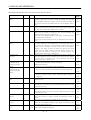
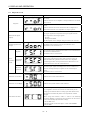
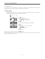
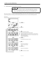
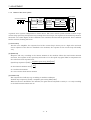
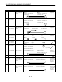
1.6 Parts Identification
Name/Application
Display
The four-digit, seven-segment LED shows the servo
status and alarm number.
Refer To
Chapter6
Operation section
Used to perform status display, diagnostic, alarm and
parameter operations.
MODE
UP
DOWN
SET
Used to set parameter
data.
Chapter6
Used to change the
display or data in each
mode.
Used to change the
mode.
I/O signal connector (CN1A)
Used to connect digital I/O signals.
Section3.3
I/O signal connector (CN1B)
Used to connect digital I/O signals.
Section3.3
Name plate
Section1.3
Servo motor connector (CNP2)
Connector for connection of the servo motor.
Section3.3
Section10.2.1
Section12.1.1
Power input connector (CNP1)
Used to connect the input power supply/control circuit
power supply/RS-422.
Section3.3
Section10.2.1
Communication connector (CNP3)
Used for connection with a personal computer
(RS-232C).
Section3.3
Section10.2.1
Section12.1.3
Earth (E) terminal ( )
To conform to the EN Standard, fit the supplied earth
terminal for grounding.
1- 5
Section3.9
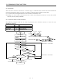
1. FUNCTIONS AND CONFIGURATION
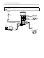
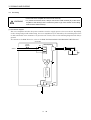
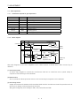
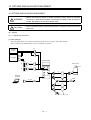
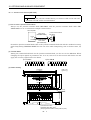
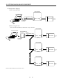
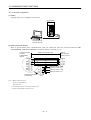
1.7 Servo System with Auxiliary Equipment
WARNING
y To prevent an electric shock, fit the supplied earth terminal (E) to the servo
amplifier (refer to (2), Section 3.9) and always connect it to the earth (E) of the
control box.
Power supply
24VDC
−
+
Servo amplifier
MITSUBISHI
MELSERVO
Circuit
protector
OPEN
CN1A
CN1B
Positioning unit/
speed controller
To CN1A
Main circuit power supply
To CNP1
CNP1
To CNP3
CNP3
Junction
terminal
block
CNP2
To CN1B
Relay
Control power supply
Servo
Configuration
software
To CNP2
Personal
computer
Earth (E) terminal
Motor cable
Power leads
Encoder
cable
Servo motor
1- 6
2. INSTALLATION
2. INSTALLATION
CAUTION
y Stacking in excess of the limited number of products is not allowed.
y Install the equipment to incombustible. Installing them directly or close to
combustibles will led to a fire.
y Install the equipment in a load-bearing place in accordance with this Instruction
Manual.
y Do not get on or put heavy load on the equipment to prevent injury.
y Use the equipment within the specified environmental condition range.
y Provide an adequate protection to prevent screws, metallic detritus and other
conductive matter or oil and other combustible matter from entering the servo
amplifier.
y Do not block the intake/exhaust ports of the servo amplifier. Otherwise, a fault may
occur.
y Do not subject the servo amplifier to drop impact or shock loads as they are
precision equipment.
y Do not install or operate a faulty servo amplifier.
y When the product has been stored for an extended period of time, consult
Mitsubishi.
2.1 Environmental conditions
Environment
Ambient temperature
Ambient humidity
storage temperature
storage humidity
Ambient
Altitude
Vibration
Conditions
0 to +55 [°C] (non-freezing)
32 to +131 [°F] (non-freezing)
90%RH or less (non-condensing)
−20 to +65 [°C] (non-freezing)
−4 to +149 [°F] (non-freezing)
90%RH or less (non-condensing)
Indoors (no direct sunlight)
Free from corrosive gas, flammable gas, oil mist, dust and dirt
Max. 1000m (3280 ft) above sea level
5.9 [m/s2] or less
19.4 [ft/s2] or less
2- 1
2. INSTALLATION
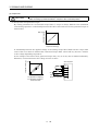
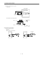
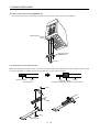
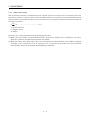
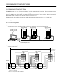
2.2 Installation direction and clearances
CAUTION
y The equipment must be installed in the specified direction. Otherwise, a fault may
occur.
y Leave specified clearances between the servo amplifier and control box inside walls
or other equipment.
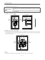
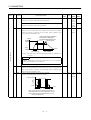
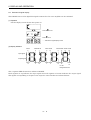
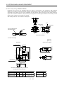
(1) Installation of one servo amplifier
Control box
Control box
40mm
(1.6 in.)
or more
Wiring clearance
Servo amplifier
MITSUBISHI
10mm
(0.4 in.)
or more
OPEN
MELSERVO
CN1A
CNP1
CN1B
10mm
(0.4 in.)
or more
Top
70mm
(2.8 in.)
CNP2
CNP3
40mm
(1.6 in.)
or more
Bottom
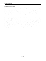
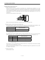
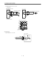
(2) Installation of two or more servo amplifiers
Leave a large clearance between the top of the servo amplifier and the internal surface of the control
box, and install a fan to prevent the internal temperature of the control box from exceeding the
environmental conditions.
Control box
100mm
(4.0 in.)
or more
MITSUBISHI
10mm
(0.4 in.)
or more
MITSUBISHI
MELSERVO
OPEN
CN1A
CNP1
1mm
(0.04 in.)
or more
MELSERVO
OPEN
CN1B
CNP2
CNP3
CN1A
CNP1
CN1B
10mm
(0.4 in.)
or more
CNP2
CNP3
40mm
(1.6 in.)
or more
(3) Others
Install the servo amplifier on a perpendicular wall in the correct vertical direction.
2- 2
2. INSTALLATION
2.3 Keep out foreign materials
(1) When installing the unit in a control box, prevent drill chips and wire fragments from entering the
servo amplifier.
(2) Prevent oil, water, metallic dust, etc. from entering the servo amplifier through openings in the control
box or a fan installed on the ceiling.
(3) When installing the control box in a place where there are much toxic gas, dirt and dust, conduct an air
purge (force clean air into the control box from outside to make the internal pressure higher than the
external pressure) to prevent such materials from entering the control box.
2.4 Cable stress
(1) The way of clamping the cable must be fully examined so that flexing stress and cable's own weight
stress are not applied to the cable connection.
(2) For use in any application where the servo motor moves, fix the cables (encoder, power supply, brake)
supplied with the servo motor, and flex the optional encoder cable or the power supply and brake
wiring cables. Use the optional encoder cable within the flexing life range. Use the power supply and
brake wiring cables within the flexing life of the cables.
(3) Avoid any probability that the cable sheath might be cut by sharp chips, rubbed by a machine corner or
stamped by workers or vehicles.
(4) For installation on a machine where the servo motor will move, the flexing radius should be made as
large as possible. Refer to section 11.4 for the flexing life.
2- 3
2. INSTALLATION
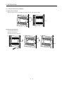
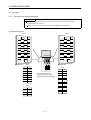
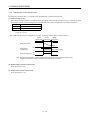
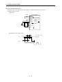
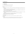
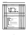
2.5 Using the DIN rail for installation
(1) Fitting into the DIN rail
Put the upper catch on the DIN rail and push the unit until it clicks.
Wall
Wall
Upper
catch
DIN rail
DIN rail
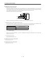
(2) Removal from DIN rail
1) Pull down the hook.
2) Pull it toward you.
3) Lift and remove the unit.
1)
Wall
2)
Wall
3)
Wall
Upper
catch
DIN rail
DIN rail
DIN rail
Hook
2- 4
3. SIGNALS AND WIRING
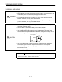
3. SIGNALS AND WIRING
WARNING
y Any person who is involved in wiring should be fully competent to do the work.
y Before starting wiring, make sure that the voltage is safe in the tester more than 15
minutes after power-off. Otherwise, you may get an electric shock.
y Ground the servo amplifier and the servo motor securely.
y Do not attempt to wire the servo amplifier and servo motor until they have been
installed. Otherwise, you may get an electric shock.
y The cables should not be damaged, stressed excessively, loaded heavily, or
pinched. Otherwise, you may get an electric shock.
y Wire the equipment correctly and securely. Otherwise, the servo motor may
misoperate, resulting in injury.
y Connect cables to correct terminals to prevent a burst, fault, etc.
y Ensure that polarity (+, −) is correct. Otherwise, a burst, damage, etc. may occur.
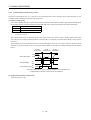
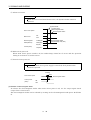
y The surge absorbing diode installed to the DC relay designed for control output
should be fitted in the specified direction. Otherwise, the signal is not output due to
a fault, disabling the forced stop and other protective circuits.
Servo amplifier
COM
(24VDC)
CAUTION
Control output
signal
RA
y Use a noise filter, etc. to minimize the influence of electromagnetic interference,
which may be given to electronic equipment used near the servo amplifier.
y Do not install a power capacitor, surge suppressor or radio noise filter with the power
line of the servo motor.
y Do not modify the equipment.
POINT
CN1A and CN1B have the same shape. Wrong connection of the connectors
will lead to a failure. Connect them correctly.
3- 1
3. SIGNALS AND WIRING
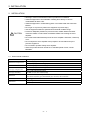
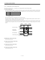
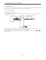
3.1 Standard connection example
POINT
y For the connection of the power supply system, refer to Section 3.7.1.
y Do not apply the test lead bars or like of a tester directly to the pins of the
connectors supplied with the servo motor. Doing so will deform the pins,
causing poor contact.
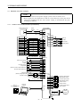
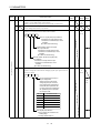
3.1.1
Position control mode AD75P
(A1SD75P
)
24VDC power supply
Circuit
protector
Servo amplifier
CNP1
RA
+
P24M
1
−
P24G
2
P24L
3
(Note 4,7)
CN1A
Signal Name Pin No.
Positioning unit AD75P/A1SD75P
(Note 4)
CN1B
PULSE F+
3
PP
3
PULSE F−
21
PG
13
PULSE R+
4
NP
2
PULSE R−
22
NG
12
5
CR
8
23
SG
10
7
RD
19
COM
26
COM
9
INPS
8
INP
18
PG0(+5V)
24
LZ
PG0 COM
25
LZR
CLEAR
CLEAR COM
READY
SD
3
VDD
13
COM
18
ALM
RA1
19
ZSP
RA2
6
TLC
RA3
(Note 2)
(Note 6)
Trouble
Zero speed
Limiting torque
5
15
Plate
(Note 8) 10m (32ft) max.
(Note 4,7)
CN1B
(Note 3) Forced stop
EMG
Servo on
SON
5
Reset
RES
14
Proportion control
PC
Torque limit
TL
15
8
9
(Note 5) Forward rotation stroke end
LSP
16
Reverse rotation stroke end
LSN
17
Upper limit setting
(Note 8) Analog torque limit
±10V/max. current
SG
10
SG
20
P15R
11 (Note 4,7)
CN1A
12
TLA
LG
1
SD
Plate
6 LA
16 LAR
7 LB
2m (6.5ft) max.
17 LBR
Encoder A-phase pulse
(differential line driver)
Encoder B-phase pulse
(differential line driver)
Control common
(Note 9)
Servo Configuration
software
1 LG
Personal
computer
CNP3
14 OP
4 P15R
Plate
Control common
Encoder Z-phase pulse
(open collector)
SD
CNP2
+
Servo
motor
30m (98ft) max.
(Note1)
3- 2
3. SIGNALS AND WIRING
Note 1. To prevent an electric shock, fit the supplied earth terminal (E) to the servo amplifier and always
connect it to the earth (E) of the control box. (Refer to section 3.9.)
2. Connect the diode in the correct direction. If it is connected reversely, the servo amplifier will be
Cfaulty and will not output signals, disabling the forced stop and other protective circuits.
3. The forced stop switch must be installed.
4. CN1A and CN1B have the same shape. Wrong connection of the connectors will lead to a fault.
5. When starting operation, always connect the forward/reverse rotation stroke end signal (LSN/LSP)
with SG. (Normally closed contacts)
6. Trouble (ALM) is connected with COM in normal alarm-free condition.
7. The pins with the same signal name are connected in the servo amplifier.
8. For the command pulse train input of the differential line driver system. 2m max. for the open
collector system.
9. Use MRZJW3-SETUP81E or later.
3- 3
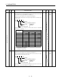
3. SIGNALS AND WIRING
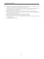
3.1.2
Speed control mode
24VDC power supply
Circuit
protector
Servo amplifier
CNP1
RA
+
P24M
1
−
P24G
2
P24L
3
(Note 4)
CN1B
3
VDD
13
COM
18
ALM
RA1
19
ZSP
RA2
6
TLC
RA3
(Note 4,7)
CN1A
Speed Selection 1
SP1
8
SG
10
SG
20
(Note 6)
Trouble
Zero speed
Limiting torque
10m (32ft) max.
(Note 4,7)
CN1B
(Note 3) Forced stop
EMG
Servo on
SON
5
Reset
RES
14
15
Speed selection 2
SP2
7
Forward rotation start
ST1
8
Reverse rotation start
ST2
9
(Note 5) Forward rotation stroke end
LSP
16
Reverse rotation stroke end
LSN
17
SG
10
SG
20
5 LZ
P15R
11
15 LZR
Upper limit setting
Analog speed command
±10V/Rated speed
Upper limit setting
(Note 8) Analog torque limit
+10V/max. current
+
RA5
Speed reached
19 RD
RA4
Ready
VC
2
6 LA
1
16 LAR
TLA
12
7 LB
17 LBR
1 LG
14 OP
4 P15R
CNP3
Encoder Z-phase pulse
(differential line driver)
Encoder A-phase pulse
(differential line driver)
Encoder B-phase pulse
(differential line driver)
Control common
Plate
2m (6.5ft) max.
(Note 9)
Servo configuration
software
18 SA
LG
SD
Personal
computer
(Note 4,7)
CN1A
Control common
Encoder Z-phase pulse
(open collector)
Plate SD
CNP2
Servo
motor
30m (98ft) max.
(Note1)
Note 1. To prevent an electric shock, fit the supplied earth terminal (E) to the servo amplifier and always
connect it to the earth (E) of the control box. (Refer to section 3.9.)
2. Connect the diode in the correct direction. If it is connected reversely, the servo amplifier will be
faulty and will not output signals, disabling the forced stop and other protective circuits.
3. The forced stop switch must be installed.
4. CN1A and CN1B have the same shape. Wrong connection of the connectors will lead to a fault.
5. When starting operation, always connect the forward/reverse rotation stroke end signal (LSN/LSP)
with SG. (Normally closed contacts)
6. Trouble (ALM) is connected with COM in normal alarm-free condition.
7. The pins with the same signal name are connected in the servo amplifier.
8. TLA can be used by setting any of parameters No. 43 to 48 to make TL available.
9. Use MRZJW3-SETUP81E or later.
3- 4
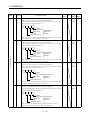
3. SIGNALS AND WIRING
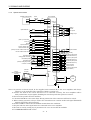
3.1.3
Torque control mode
24VDC power supply
Circuit
protector
Servo amplifier
CNP1
RA
+
P24M
1
−
P24G
2
P24L
3
(Note 4)
CN1B
(Note 4,6)
CN1A
Speed Selection 1
SP1
8
SG
10
SG
20
3
VDD
13
COM
18
ALM
RA1
19
ZSP
RA2
6
TLC
RA3
(Note 2)
(Note 5)
Trouble
Zero speed
Limiting torque
10m(32ft) max.
(Note 4,6)
CN1B
(Note 3) Forced stop
EMG
Servo on
SON
5
Reset
RES
14
15
Speed selection2
SP2
7
Forward rotation selection
RS1
9
Reverse rotation selection
RS2
8
SG
10
Upper limit setting
Analog torque command
±8V/max. current
Upper limit setting
Analog speed limit
0 to +10V/max. speed
SG
20
P15R
11
(Note 4,6)
CN1A
19 RD
TC
12
5 LZ
LG
1
15 LZR
VLA
2
SD
Plate
RA4
6 LA
16 LAR
7 LB
17 LBR
2m (6.5ft) max.
Encoder Z-phase pulse
(differential line driver)
Encoder A-phase pulse
(differential line driver)
Encoder B-phase pulse
(differential line driver)
Control common
1 LG
(Note 7)
Servo configuration
software
Ready
Personal
computer
14 OP
CNP3
4 P15R
Plate
Control common
Encoder Z-phase pulse
(open collector)
SD
+
CNP2
Servo
motor
30m (98ft) max.
(Note1)
Note 1. To prevent an electric shock, fit the supplied earth terminal (E) to the servo amplifier and always
connect it to the earth (E) of the control box. (Refer to section 3.9.)
2. Connect the diode in the correct direction. If it is connected reversely, the servo amplifier will be
faulty and will not output signals, disabling the forced stop and other protective circuits.
3. The forced stop switch must be installed.
4. CN1A and CN1B have the same shape. Wrong connection of the connectors will lead to a fault.
5. Trouble (ALM) is connected with COM in normal alarm-free condition.
6. The pins with the same signal name are connected in the servo amplifier.
7. Use MRZJW3-SETUP81E or later.
3- 5
3. SIGNALS AND WIRING
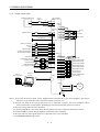
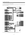
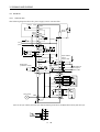
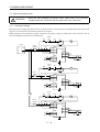
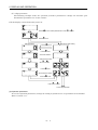
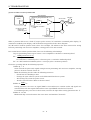
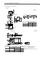
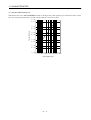
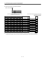
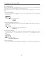
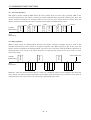
3.2 Internal Connection Diagram of Servo Amplifier
The following is the internal connection diagram where the signal assignment has been made in the initial
status in each control mode.
Servo amplifier
CNP2
2
CNP1
P24M 1
2
7
V
P24L
3
8
W
1
E
(Note)
P
S
T
CN1B
CNP2
VDD
VDD
VDD
3
3
COM COM COM
13
9
(Note)
P
U
P24G
B2
B1
(Note)
S
T
COM COM COM
CN1A
9
CR
SP1
SP1
8
SG
SG
SG
10,20
Approx.4.7k
S
T
CN1B
SON
SON
SON
5
SP2
SP2
7
PC
ST1
RS2
8
TL
ST2
RS1
9
RES
RES
RES
14
EMG EMG EMG
15
LSP
LSP
16
LSN
LSN
17
SG
SG
SG
P
S
18
INP
SA
19
RD
RD
T
RD
(Note)
(Note)
P
CN1A
Approx.4.7k
Approx.4.7k
Approx.4.7k
Approx.4.7k
CN1B
P
S
T
6
TLC
TLC
VLC
18
ALM
ALM
ALM
19
ZSP
ZSP
ZSP
4
DO1
DO1
DO1
Approx.4.7k
Approx.4.7k
Approx.4.7k
Approx.4.7k
(Note)
10,20
CN1A
P
S
T
CN1A
6
LA
LA
LA
OPC
11
16
LAR
LAR
LAR
PG
13
7
LB
LB
LB
(Note)
P
S
T
Approx.100Ω
Approx.1.2kΩ
PP
3
17
LBR
LBR
LBR
NG
12
5
LZ
LZ
LZ
2
15
LZR
LZR
LZR
Case
14
OP
OP
OP
1
LG
LG
LG
NP
SD
SD
SD
Approx.100Ω
Approx.1.2kΩ
(Note)
P
TLA
S
T
CN1B
VC
VLA
2
TLA
TC
12
P15R P15R P15R
11
LG
LG
LG
1
SD
SD
SD
Case
S
T
CN1A
+15VDC
E
(Note)
P
P15R P15R P15R
4
Note. P: Position control mode, S: Speed control mode, T: Torque control mode
3- 6
3. SIGNALS AND WIRING
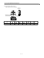
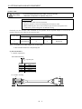
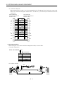
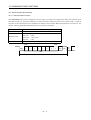
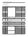
3.3 I/O Signals
3.3.1
Connectors and signal arrangements
POINT
The pin configurations of the connectors are as viewed from the cable
connector wiring section.
Refer to the next page for CN1A and CN1B signal assignment.
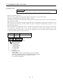
(1) Signal arrangement
CN1A
CN1B
1
2
11
3
2
5
6
3
15
5
6
17
18
MELSERVO
20
10
CNP1CNP2
5
1
RDP
P24M
6
2
RDN
P24G
7
3
SDP
P24L
8
4
SDN
TRE
CNP2
CNP3
The connector frames are
connected with the E (earth)
terminal inside the servo amplifier.
6
12
MR
MRR
5
11
P5
LG
4
10
SD
3
9
B2
B1
2
8
1
U
W
SD
LG
1
7
4
2
E
V
TXD
RXD
CNP3
3
3- 7
19
9
20
CNP1
17
7
8
19
9
15
16
MITSUBISHI
18
8
13
14
4
16
7
11
12
13
14
4
10
1
12
3. SIGNALS AND WIRING
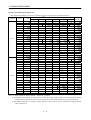
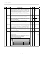
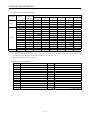
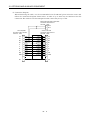
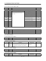
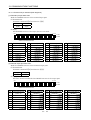
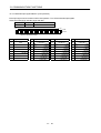
(2) CN1A and CN1B signal assignment
The signal assignment of connector changes with the control mode as indicated below;
(Note2)
Connector
I/O
1
I
3
I
NP
PP
P15R
P/S
S
S/T
T
LG
LG
LG
LG
P15R
P15R
P15R
NP/
T/P
/PP
PP/
P15R/P15R
P15R
0
LZ
LZ
LZ
LZ
LZ
LZ
6
0
LA
LA
LA
LA
LA
LA
7
0
LB
LB
LB
LB
LB
LB
8
I
CR
CR/SP1
(Note3)SP1
SP1/SP1
(Note3)SP1
SP1/CR
COM
COM
COM
COM
COM
COM
SG
SG
SG
SG
10
SG
11
OPC
OPC/
/OPC
/NG
12
I
NG
NG/
13
I
PG
PG/
14
0
OP
OP
OP
OP
OP
0
LZR
LZR
LZR
LZR
LZR
LZR
16
0
LAR
LAR
LAR
LAR
LAR
LAR
17
0
LBR
LBR
LBR
LBR
LBR
LBR
18
0
INP
INP/SA
SA
19
0
RD
RD
RD
RD
RD
SA/
RD
/INP
20
SG
SG
SG
SG
SG
SG
1
LG
LG
LG
LG
LG
LG
/VC
VC
VC/VLA
VLA
VDD
VDD
VDD
VDD
I
3
VDD
No.43 to 48
/PG
OP
15
2
Related
parameter
LG
/NP
5
9
No.49
No.49
VLA/
VDD
(Note3,4)4
0
DO1
DO1
DO1
DO1
DO1
DO1
(Note3)5
I
SON
SON
SON
SON
SON
SON
(Note3)6
0
TLC
TLC
TLC
TLC/VLC
VLC
VLC/TLC
No.49
(Note3)7
I
LOP
SP2
LOP
SP2
LOP
No.43 to 48
(Note3)8
I
PC/ST1
(Note4)ST1
ST1/RS2
(Note4)RS2
RS2/PC
No.43 to 48
RS1/TL
No.43 to 48
(Note3)9
CN1B
P
LG
2
4
CN1A
I/O Signals in Control Modes
(Note1)
Pin No.
TL
TL/ST2
(Note5)ST2
ST2/RS1
(Note5)RS1
10
SG
SG
SG
SG
SG
SG
11
P15R
P15R
P15R
P15R
P15R
P15R
TC
TC/TLA
12
I
PC
I
13
TLA
(Note6)
TLA/TLA
TLA
(Note6)
TLA/TC
COM
COM
COM
COM
COM
COM
14
I
RES
RES
RES
RES
RES
RES
15
I
EMG
EMG
EMG
EMG
EMG
16
I
LSP
LSP
LSP
LSP/
LSN/
No.43 to 48
No.43 to 48
EMG
/LSP
/LSN
17
I
LSN
LSN
LSN
18
0
ALM
ALM
ALM
ALM
ALM
ALM
No.49
19
0
ZSP
ZSP
ZSP
ZSP
ZSP
ZSP
No.1,49
SG
SG
SG
SG
SG
SG
20
Note 1. I: Input signal, O: Output signal, -: Others (e. g. power)
2. P: Position control mode, S: Speed control mode, T: Torque control mode, P/S: Position/speed control
change mode, S/T: Speed/torque control change mode, T/P: Torque/position control change mode
3. The signal of CN1A-18 is always output. However, this pin may not be used when assigning alarm
codes to CN1A-18.
3- 8
3. SIGNALS AND WIRING
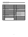
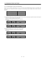
(3) Symbols and signal names
Symbol
SON
LSP
LSN
CR
SP1
SP2
PC
ST1
ST2
TL
RES
EMG
LOP
VC
VLA
TLA
TC
RS1
RS2
PP
NP
PG
NG
Signal Name
Servo on
Forward rotation stroke end
Reverse rotation stroke end
Clear
Speed selection 1
Speed selection 2
Proportion control
Forward rotation start
Reverse rotation start
Torque limit selection
Reset
Forced stop
Control change
Analog speed command
Analog speed limit
Analog torque limit
Analog torque command
Forward rotation selection
Reverse rotation selection
Forward/reverse rotation pulse train
Symbol
TLC
VLC
RD
ZSP
INP
SA
ALM
WNG
OP
MBR
LZ
LZR
LA
LAR
LB
LBR
VDD
COM
OPC
SG
P15R
LG
SD
3- 9
Signal Name
Limiting torque
Limiting speed
Ready
Zero speed
In position
Speed reached
Trouble
Warning
Encoder Z-phase pulse (open collector)
Electromagnetic brake interlock
Encoder Z-phase pulse
(differential line driver)
Encoder A-phase pulse
(differential line driver)
Encoder B-phase pulse
(differential line driver)
I/F internal power supply
Digital I/F power supply input
Open collector power input
Digital I/F common
DC15V power supply
Control common
Shield
3. SIGNALS AND WIRING
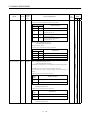
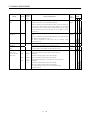
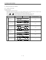
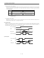
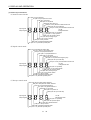
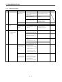
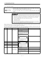
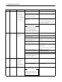
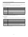
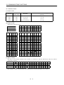
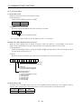
3.3.2
Signal explanations
For the I/O interfaces (symbols in I/O column in the table), refer to Section 3.6.2.
In the Control Mode field of the table
P : Position control mode, S: Speed control mode, T: Torque control mode
{: Denotes that the signal may be used in the initial setting status.
∆ : Denotes that the signal may be used by setting the corresponding parameter among parameters 43 to
49.
The pin No.s in the connector pin No. column are those in the initial status.
(1) Input signals
Signal
Servo-on
Reset
Forward rotation
stroke end
ConnecSymbol tor Pin
No.
SON
RES
LSP
CN1B
5
CN1B
14
CN1B
16
Functions/Applications
Ready signal input terminal.
Connect SON-SG to switch on the base circuit and make the servo
amplifier ready to operate (servo on).
Disconnect SON-SG to shut off the base circuit and coast the
servo motor (servo off) .
Set1 in parameter No. 41 to switch this signal on
(keep terminals connected) automatically in the servo
amplifier.
DI-1
Alarm reset signal input terminal.
Disconnect RES-SG for more than 50ms to reset the alarm.
Some alarms cannot be deactivated by the reset signal. Refer to
Section 9.2.
Turning RES on in an alarm-free status shuts off the base circuit.
DI-1
Forward/reverse rotation stroke end signal input terminals.
To start operation, short LSP-SG and/or LSN-SG. Open them to
bring the motor to a sudden stop and make it servo-locked.
Set1 in parameter No. 22 to make a slow stop.
DI-1
(Note) Input signals
LSP
Reverse rotation
stroke end
LSN
CN1B
17
I/O
Division
1
1
1
1
0
0
0
P
S
{ { {
Operation
{
{
{
{
{ {
Note. 0: OFF (LSP/LSN-SG open)
1: ON (LSP/LSN-SG shorted)
Set parameter No. 41 as indicated below to switch on the signals
(keep terminals connected) automatically in the servo amplifier:
Parameter No.41
Automatic ON
1
LSP
1
LSN
3 - 10
T
{ { {
CCW
CW
direction direction
LSN
0
Control
Mode
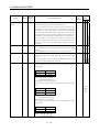
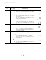
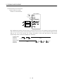
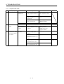
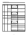
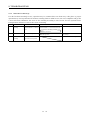
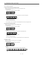
3. SIGNALS AND WIRING
Signal
Torque limit
Forward rotation
start
Reverse rotation
start
ConnecSymbol tor Pin
No.
TL
ST1
ST2
I/O
Division
Functions/Applications
CN1B
9
Torque limit selection input device.
Short TL-SG to make the analog torque limit valid.
For details, refer to (2), section 3.4.1.
DI-1
CN1B
8
Used to start the servo motor in any of the following directions:
DI-1
CN1B
9
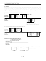
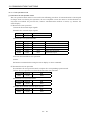
(Note) Input signals
Control
Mode
P
S
T
{ ∆
Servo Motor Starting Direction
ST2
ST1
0
0
Stop (servo lock)
0
1
CCW
1
0
CW
1
1
Stop (servo lock)
{
Note. 0: OFF (ST1/ST2-SG open)
1: ON (ST1/ST2-SG shorted)
If both ST1 and ST2 are switched on or off during operation, the
servo motor will be decelerated to a stop according to the
parameter No. 12 setting and servo-locked.
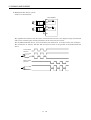
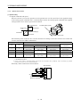
Forward rotation
selection
RS1
CN1B
9
Used to select any of the following servo motor torque generation
directions:
(Note) Input signals
Reverse rotation
selection
RS2
CN1B
8
Torque Generation
Direction
Rotation Direction
0
Torque is not
generated
Stop
1
Forward rotation in
driving mode / reverse
rotation in
regenerative mode
CCW
RS2
RS1
0
0
1
0
1
1
Reverse rotation in
driving mode /
forward rotation in
regenerative mode
Torqueis not
generated
Note. 0: OFF (RS1/RS2-SG open)
1: ON (RS1/RS2-SG shorted)
3 - 11
DI-1
{
CW
Stop
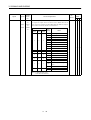
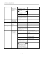
3. SIGNALS AND WIRING
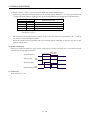
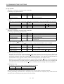
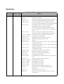
Signal
Speed selection 1
ConnecSymbol tor Pin
No.
SP1
CN1A
8
Functions/Applications
<Speed control mode>
Used to select the command speed for operation.
(Note) Input signals
SP2
SP1
0
0
I/O
Division
Control
Mode
P
S
T
DI-1
Speed Command
Analog speed command (VC)
0
1
Internal speed command 1
(parameter No. 8)
1
0
Internal speed command 2
(parameter No. 9)
1
1
Internal speed command 3
(parameter No. 10)
Note. 0: OFF (SP1/SP2-SG open)
1: ON (SP1/SP2-SG shorted)
<Torque control mode>
Used to select the limit speed for operation.
(Note) Input signals
Speed selection 2
SP2
CN1B
7
Speed Limit
SP2
SP1
0
0
Analog speed limit (VLA)
0
1
Internal speed limit 1 (parameter No. 8)
1
0
Internal speed limit 2 (parameter No. 9)
1
1
Internal speed limit 3 (parameter No. 10)
Note. 0: OFF (SP1/SP2-SG open)
1: ON (SP1/SP2-SG shorted)
<Position/speed, speed/torque, torque/position control change mode>
As CN1B-7 acts as a control change signal, the speed
selected when the speed or torque control mode is selected is as
follows:
x When speed control mode is selected
(Note)
SP1
Speed Command
0
Analog speed command (VC)
1
Internal speed command 1 (parameter No. 8)
Note. 0: OFF (SP1-SG open)
1: ON (SP1-SG shorted)
x When torque control mode is selected
(Note)
SP1
Speed Limit
0
Analog speed limit (VLA)
1
Internal speed limit 1 (parameter No. 8)
Note. 0: OFF (SP1-SG open)
1: ON (SP1-SG shorted)
3 - 12
{ {
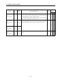
3. SIGNALS AND WIRING
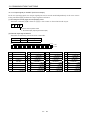
Signal
Proportion
control
Forced stop
Clear
Control change
ConnecSymbol tor Pin
No.
PC
EMG
CR
LOP
Functions/Applications
I/O
Division
Connect PC-SG to switch the speed amplifier from the
proportional integral type to the proportional type.
If the servo motor at a stop is rotated even one pulse due to any
external factor, it generates torque to compensate for a position
shift. When the servo motor shaft is to be locked mechanically
after positioning completion (stop), switching on the proportion
control signal (PC) upon positioning completion will suppress the
unnecessary torque generated to compensate for a position shift.
When the shaft is to be locked for a long time, switch on the
proportion control signal and torque control signal (TL) at the
same time to make the torque less than the rated by the analog
torque limit.
DI-1
CN1B
15
Disconnect EMG-SG to bring the servo motor to a forced stop
state, in which the servo is switched off and the dynamic brake is
operated.
Connect EMG-SG in the forced stop state to reset that state.
DI-1
CN1A
8
Connect CR-SG to clear the position control counter droop pulses
on the leading edge of the signal. The pulse width should be 10ms
or more.
When the parameter No. 42 setting is 1, the pulses are
always cleared while CR-SG are connected.
DI-1
<Position/speed control change mode>
Used to select the control mode in the position/speed control
change mode.
DI-1
CN1B
8
CN1B
7
(Note) LOP
Control Mode
0
Position
1
Speed
Control
Mode
P
S
T
{ ∆
{ { {
{
Note. 0: OFF (LOP-SG open)
1: ON (LOP-SG shorted)
<Speed/torque control change mode>
Used to select the control mode in the speed/torque control change
mode.
Refer to
(Note) LOP
Control Mode
0
Speed
1
Torque
Note. 0: OFF (LOP-SG open)
1: ON (LOP-SG shorted)
<Torque/position control mode>
Used to select the control mode in the torque/position control
change mode.
(Note) LOP
Control Mode
0
Torque
1
Position
Note. 0: OFF (LOP-SG open)
1: ON (LOP-SG shorted)
3 - 13
Functions/
Applications.
3. SIGNALS AND WIRING
Signal
Analog torque
limit
Analog torque
command
ConnecSymbol tor Pin
No.
TLA
TC
Analog speed
command
VC
Analog speed
limit
VLA
Forward rotation
pulse train
Reverse rotation
pulse train
CN1B
12
PP
NP
PG
NG
CN1B
2
CN1A
3
CN1A
2
CN1A
13
CN1A
12
Functions/Applications
I/O
Division
To use this signal in the speed control mode, set any of
parameters No. 43 to 48 to make TL available.
When the analog torque limit (TLA) is valid, torque is limited in
the full servo motor output torque range. Apply 0 to +10 VDC
across TLA-LG. Connect the positive terminal of the power supply
to TLA. Maximum torque is generated at +10 V. (Refer to (2) in
Section 3.4.1.)
Analog
input
Used to control torque in the full servo motor output torque
range.
Apply 0 to ±8VDC across TC-LG. Maximum torque is generated at
±8V. (Refer to (1) in Section 3.4.3.)
The torque generated at ±8V input can be changed using
parameter No. 26.
Analog
input
Apply 0 to ±10VDC across VC-LG. Speed set in parameter No. 25
is provided at ±10V. (Refer to (1) in Section 3.4.2.)
Analog
input
Apply 0 to ±10VDC across VLA-LG. Speed set in parameter No.
25 is provided at ±10V. (Refer to (3) in Section 3.4.3.)
Analog
input
Used to enter a command pulse train.
x In the open collector system (max. input frequency
200kpps):
Forward rotation pulse train across PP-SG
Reverse rotation pulse train across NP-SG
x In the differential receiver system (max. input frequency
500kpps):
Forward rotation pulse train across PG-PP
Reverse rotation pulse train across NG-NP
The command pulse train form can be changed using
parameter No. 21.
DI−2
3 - 14
Control
Mode
P
S
T
{ ∆
{
{
{
{
3. SIGNALS AND WIRING
(2) Output signals
Signal
Trouble
ConnecSymbol tor Pin
No.
ALM
Functions/Applications
I/O
Division
CN1B
18
ALM-SG are disconnected when power is switched off or the
protective circuit is activated to shut off the base circuit. Without
alarm, ALM-SG are connected within about 1s after power on.
DO−1
RD
CN1A
19
RD-SG are connected when the servo is switched on and the servo
amplifier is ready to operate.
DO−1
In position
INP
CN1A
18
INP-SG are connected when the number of droop pulses is in the
preset in-position range. The in-position range can be changed
using parameter No. 5.
When the in-position range is increased, INP-SG may be kept
connected during low-speed rotation.
DO−1
SA turns off when servo on (SON) turns off or the servomotor
speed has not reached the preset speed with both forward rotation
start (ST1) and reverse rotation start (ST2) turned off. SA turns
on when the servomotor speed has nearly reached the preset
speed. When the preset speed is 20r/min or less, SA always turns
on.
DO−1
CN1B
6
VLC-SG are connected when speed reaches the value set to any of
the internal speed limits 1 to 3 (parameters No. 8 to 10) or the
analog speed limit (VLA) in the torque control mode. They are
disconnected when the servo-on signal (SON) switches off.
DO−1
CN1B
6
TLC-SG are connected when the torque generated reaches the
value set to the internal torque limit 1 (parameter No. 28) or
analog torque limit (TLA). They are disconnected when the servoon signal (SON) switches off.
DO−1
CN1B
19
ZSP-SG are connected when the servo motor speed is zero speed
(50r/min) or less. Zero speed can be changed using parameter No.
24.
DO−1
CN1B
19
Set1 in parameter No. 1 to use this parameter. Note that
ZSP will be unusable.
In the servo-off or alarm status, MBR-SG are disconnected.
When an alarm occurs, they are disconnected independently of
the base circuit status.
DO−1
To use this signal, assign the connector pin for output using
parameter No. 49. The old signal before assignment will be
unusable.
When warning has occurred, WNG-SG are connected.
When there is no warning, WNG-SG are disconnected within
about 1s after power-on.
DO−1
Limiting speed
Limiting torque
Zero speed
Electromagnetic
brake interlock
Warning
SA
VLC
TLC
ZSP
MBR
WNG
3 - 15
P
S
T
{ { {
Ready
Speed reached
Control
Mode
{ { {
{
{
{
{ {
{ { {
∆
∆
∆
∆
∆
∆
3. SIGNALS AND WIRING
Signal
Alarm code
ConnecSymbol tor Pin
No.
ACD0
ACD1
ACD2
CN1A
19
CN1A
18
CN1B
19
I/O
Division
Functions/Applications
To use this signal, set 1 in parameter No. 49.
This signal is output when an alarm occurs. When there is no
alarm, respective ordinary signals (RD, INP, SA, ZSP) are output.
Alarm codes and alarm names are listed below:
(Note) Alarm Code
Alarm
CN1B CN1A CN1A
Display
19 Pin 18 Pin 19 Pin
0
0
0
8888
Watchdog
A. 11
Board error 1
A. 12
Memory error 1
A. 13
Clock error
A. 15
Memory error 2
A. 17
Board error 2
A. 18
Board error 3
A. 37
Parameter error
A. 8E
RS-232C error
0
1
A. 33
Overvoltage
0
1
0
A. 10
Undervoltage
0
1
1
A. 50
Overload 1
A. 51
Overload 2
1
1
0
0
1
0
1
0
A. 24
Motor output ground fault
A. 32
Overcurrent
A. 31
Overspeed
A. 35
Command pulse frequency
alarm
A. 52
Error excessive
A. 16
Encoder error 1
A. 20
Encoder error 2
Note. 0: OFF (Pin-SG open)
1: ON (Pin-SG shorted)
3 - 16
P
S
T
∆
∆
∆
DO−1
Name
0
1
Control
Mode
3. SIGNALS AND WIRING
Signal
ConnecSymbol tor Pin
No.
Encoder Z-phase
pulse
(Open collector)
OP
Encoder A-phase
pulse
(Differential line
driver)
LA
LAR
CN1A
14
CN1A
6
CN1A
16
Functions/Applications
I/O
Division
Outputs the zero-point signal of the encoder. One pulse is output
per servo motor revolution. OP and LG are connected when the
zero-point position is reached. ( Negative logic)
The maximum pulse width is about 400µs. For zeroing using this
pulse, set the creep speed to 100r/min. or less.
DO−2
Outputs pulses per servo motor revolution set in parameter No.
27 in the differential line driver system. The encoder B-phase
pulse lags the encoder A-phase pulse by a phase angle of π/2.
DO−2
Control
Mode
P
S
T
{ { {
{ { {
Encoder B-phase
pulse
(Differential line
driver)
Encoder Z-phase
pulse
(Differential line
driver)
LB
LBR
LZ
LZR
CN1A
7
CN1A
17
CN1A
5
CN1A
15
The same signal as OP is output in the differential line driver
system.
3 - 17
DO−2
{ { {
3. SIGNALS AND WIRING
(3) Power supply
Signal
ConnecSymbol tor Pin
No.
Functions/Applications
I/O
Division
Control
Mode
P
S
T
I/F internal
power supply
VDD
CN1B
3
Used to output 24VDC for input interface.
Connected with P24L inside the servo amplifier.
{ { {
Digital I/F power
supply input
COM
CN1A
9
CN1B
13
Used to input 24VDC for input interface.
Connect the positive terminal of the 24VDC external power
supply.
24VDC±10%
{ { {
Open collector
power input
OPC
CN1A
11
When inputting a pulse train in the open collector system, supply
this terminal with the positive (+) power of 24VDC.
{ { {
SG
CN1A
10
20
CN1B
10
20
Common terminal for input signals such as SON and EMG. Pins
are connected internally.
Internally connected with LG.
CN1A
4
CN1B
11
Outputs 15VDC to across P15R-LG. Available as power for TC,
TLA, VC, VLA.
Permissible current: 30mA
CN1A
1
CN1B
1
CN3
1
3
5
11
13
15
Common terminal for TLA, TC, VC, VLA, FPA, FPB, OP and
P15R.
Pins are connected internally.
Plate
Connect the external conductor of the shield cable.
Digital I/F
common
DC15V power
supply
Control common
Shield
P15R
LG
SD
{ { {
{ { {
{ { {
3 - 18
{ { {
3. SIGNALS AND WIRING
3.4 Detailed Description of the Signals
3.4.1
Position control mode
(1) Pulse train input
(a) Input pulse waveform selection
Command pulses may be input in any of three different forms, for which positive or negative logic
can be chosen. Set the command pulse train form in parameter No. 21.
or
in the table indicates the timing of importing a pulse train.
Arrow
A- and B-phase pulse trains are imported after they have been multiplied by 4.
Pulse Train Form
Negative logic
Forward rotation
pulse train
Reverse rotation
pulse train
Forward Rotation
Reverse Rotation
Parameter No. 21
(Command pulse train)
PP
0010
NP
PP
Pulse train + sign
0011
NP
L
H
PP
A-phase pulse train
B-phase pulse train
0012
NP
Positive logic
Forward rotation
pulse train
Reverse rotation
pulse train
PP
0000
NP
PP
Pulse train + sign
0001
NP
L
H
PP
A-phase pulse train
B-phase pulse train
0002
NP
3 - 19
3. SIGNALS AND WIRING
(b) Connections and waveforms
1) Open collector system
Connect as shown below:
Servo amplifier
24VDC
P24G
P24L
VDD
OPC
PP
About 2kΩ
NP
About 2kΩ
SG
SD
The explanation assumes that the input waveform has been set to the negative logic and forward
and reverse rotation pulse trains (parameter No.21 has been set to 0010). The waveforms in the
table in (a), (1) of this section are voltage waveforms of PP and NP based on SG. Their
relationships with transistor ON/OFF are as follows:
Forward rotation
pulse train
(transistor)
Reverse rotation
pulse train
(transistor)
(OFF) (ON) (OFF) (ON)
(OFF)
(OFF)
(ON) (OFF) (ON) (OFF) (ON)
3 - 20
3. SIGNALS AND WIRING
2) Differential line driver system
Connect as shown below:
Servo amplifier
PP
PG
NP
NG
SD
The explanation assumes that the input waveform has been set to the negative logic and forward
and reverse rotation pulse trains (parameter No.21 has been set to 0010).
For the differential line driver, the waveforms in the table in (a), (1) of this section are as follows.
The waveforms of PP, PG, NP and NG are based on that of the ground of the differential line
driver.
Forward rotation
pulse train
PP
PG
Reverse rotation
pulse train
NP
NG
3 - 21
3. SIGNALS AND WIRING
(2) Torque limit
If the torque limit is canceled during servo lock, the servomotor may suddenly
rotate according to position deviation in respect to the command position.
CAUTION
(a) Torque limit and generated torque
By setting parameter No. 28 (internal torque limit 1), torque is always limited to the maximum
value during operation. A relationship between the limit value and servo motor-generated torque is
shown below.
Generated torque
Max. torque
0
0
100
Torque limit value [%]
Torque limit value [%]
A relationship between the applied voltage of the analog torque limit (TLA) and the torque limit
value of the servo motor is shown below. Generated torque limit values will vary about 5% relative
to the voltage depending on products.
At the voltage of less than 0.05V, generated torque may vary as it may not be limited sufficiently.
Therefore, use this function at the voltage of 0.05V or more.
Servo amplifier
100
TL
SG
±5%
0
0 0.05
2kΩ
10
TLA application voltage [V]
2kΩ
Japan Resistor
RRS10 or equivalent
TLA application voltage vs.
torque limit value
3 - 22
P15R
TLA
LG
SD
3. SIGNALS AND WIRING
(b) Torque limit value selection
Choose the torque limit made valid by the internal torque limit value 1 (parameter No. 28) using the
external torque limit selection (TL) or the torque limit made valid by the analog torque limit (TLA)
as indicated below:
Torque Limit Value Made Valid
(Note) TL
If TLA > Parameter No. 28
If TLA < Parameter No. 28
Internal torque limit value 1
(parameter No. 28)
0
Internal torque limit value 1
(parameter No. 28)
1
Analog torque limit (TLA)
Note. 0: TLA-SG off (open)
1: TLA-SG on (short)
(c) Limiting torque (TLC)
TLC-SG are connected when the torque generated by the servo motor reaches the torque set to
internal torque limit value 1 or analog torque limit.
(3) In-position (INP)
PF-SG are connected when the number of droop pulses in the deviation counter falls within the preset
in-position range (parameter No. 5). INP-SG may remain connected when low-speed operation is
performed with a large value set as the in-position range.
Servo-on (SON)
Alarm
ON
OFF
Yes
No
In-position range
Droop pulses
In position (INP)
ON
OFF
(4) Ready (RD)
Servo-on (SON)
Alarm
Ready (RD)
ON
OFF
Yes
No
ON
80ms or less
OFF
3 - 23
10ms or less
10ms or less
3. SIGNALS AND WIRING
3.4.2
Speed control mode
(1) Speed setting
(a) Speed command and speed
The servo motor is run at the speeds set in the parameters or at the speed set in the applied voltage
of the analog speed command (VC). A relationship between the analog speed command (VC) applied
voltage and the servo motor speed is shown below:
Rated speed [r/min]
Speed [r/min]
−10
CW direction
Forward rotation (CCW)
CCW direction
0
+10
VC applied voltage [V]
Rated speed
Reverse rotation (CW)
The following table indicates the rotation direction according to forward rotation start (ST1) and
reverse rotation start (ST2) combination:
(Note 1) External Input Signals
(Note 2)Rotation Direction
Analog Speed Command (VC)
+ Polarity
0V
− Polarity
Internal Speed
Commands
0
Stop
(Servo lock)
Stop
(Servo lock)
Stop
(Servo lock)
Stop
(Servo lock)
0
1
CCW
CCW
0
CW
Stop
(No servo lock)
CW
1
CCW
CW
1
Stop
(Servo lock)
Stop
(Servo lock)
Stop
(Servo lock)
Stop
(Servo lock)
ST2
ST1
0
1
Note 1. 0: ST1/ST2-SG off (open)
1: ST1/ST2-SG on (short)
2. If the torque limit is canceled during servo lock, the servomotor may suddenly rotate according to position
deviation in respect to the command position.
Generally, make connection as shown below:
Servo amplifier
2kΩ
2kΩ
Japan Resistor
RRS10 or equivalent
3 - 24
SP1
SP2
SG
P15R
VC
LG
SD
3. SIGNALS AND WIRING
(b) Speed selection 1 (SP1), speed selection 2 (SP2) and speed command value
Choose any of the speed settings made by the internal speed commands 1 to 3 using speed selection
1 (SP1) and speed selection 2 (SP2) or the speed setting made by the analog speed command (VC).
(Note) External Input Signals
SP2
Speed Command Value
SP1
0
0
Analog speed command (VC)
0
1
Internal speed command 1 (parameter No. 8)
1
0
Internal speed command 2 (parameter No. 9)
1
1
Internal speed command 3 (parameter No. 10)
Note. 0: SP1/SP2-SG off (open)
1: SP1/SP2-SG on (short)
The speed may be changed during rotation. In this case, the values set in parameters No. 11 and 12
are used for acceleration/deceleration.
When the speed has been specified under any internal speed command, it does not vary due to the
ambient temperature.
(2) Speed reached (SA)
SA-SG are connected when the servo motor speed nearly reaches the speed set to the internal speed
command or analog speed command.
Internal speed
command 1
Set speed selection
Start (ST1,ST2)
ON
OFF
Servo motor speed
Speed reached (SA)
ON
OFF
(3) Torque limit
As in Section 3.4.1 (2).
3 - 25
Internal speed
command 2
3. SIGNALS AND WIRING
3.4.3
Torque control mode
(1) Torque control
(a) Torque command and generated torque
A relationship between the applied voltage of the analog torque command (TC) and the torque
generated by the servo motor is shown below.
The maximum torque is generated at ±8V. Note that the torque generated at ±8V input can be
changed with parameter No. 26.
CCW direction
Max. torque
Forward rotation (CCW)
Generated torque
−8 −0.05
+0.05 +8
TC applied voltage [V]
CW direction
Max. torque (Note)
Reverse rotation (CW)
Generated torque limit values will vary about 5% relative to the voltage depending on products.
Generated torque may vary at the voltage of −0.05V to +0.05V.
The following table indicates the torque generation directions determined by the forward rotation
selection (RS1) and reverse rotation selection (RS2) when the analog torque command (TC) is used.
(Note) External Input Signals
Rotation Direction
Torque control Command (TC)
RS2
RS1
0
0
Torque is not generated
1
CCW (reverse rotation in
driving mode/forward
rotation in regenerative
mode)
1
0
CW (forward rotation in
driving mode/reverse
rotation in regenerative
mode)
1
1
0
+ Polarity
0V
No torque
Torque is not generated
CW (forward rotation in
driving mode/reverse
rotation in regenerative
mode)
CCW (reverse rotation in
driving mode/forward
rotation in regenerative
mode)
Torque is not generated
Note. 0: RS1/RS2-SG off (open)
1: RS1/RS2-SG on (short)
Generally, make connection as shown below:
Servo amplifier
−8 to +8V
− Polarity
Torque is not generated
RS1
RS2
SG
TC
LG
SD
3 - 26
3. SIGNALS AND WIRING
(b) Analog torque command offset
Using parameter No. 30, the offset voltage of -999 to +999mV can be added to the TC applied
voltage as shown below.
Generated torque
Max. torque
0
Parameter No.30 offset range
−999 to +999mV
+8(−8)
TC applied voltage [V]
(2) Torque limit
By setting parameter No. 28 (internal torque limit 1), torque is always limited to the maximum value
during operation. A relationship between limit value and servo motor-generated torque is as in (2) in
section 3.4.1. Note that the analog torque limit (TLA) is unavailable.
(3) Speed limit
(a) Speed limit value and speed
The speed is limited to the values set in parameters No. 8 to 10 (internal speed limits 1 to 3) or the
value set in the applied voltage of the analog speed limit (VLA).
A relationship between the analog speed limit (VLA) applied voltage and the servo motor speed is
shown below.
When the motor speed reaches the speed limit value, torque control may become unstable. Make the
set value more than 100r/min smaller than the desired speed limit value.
Rated speed
Speed [r/min]
Forward rotation (CCW)
CCW direction
−10
0
+10
VLA applied voltage [V]
CW direction
Rated speed
Reverse rotation (CW)
The following table indicates the limit direction according to forward rotation selection (RS1) and
reverse rotation selection (RS2) combination:
(Note) External Input Signals
RS1
RS2
1
0
0
1
Speed Limit Direction
Analog Speed Limit (VLA)
+ Polarity
− Polarity
CCW
CW
CW
CCW
Note. 0: RS1/RS2-SG off (open)
1: RS1/RS2-SG on (short)
Generally, make connection as shown below:
Servo amplifier
2kΩ
2kΩ
Japan Resistor
RRS10 or equivalent
3 - 27
SP1
SP2
SG
P15R
VC
LG
SD
Internal Speed
Commands
CCW
CW
3. SIGNALS AND WIRING
(b) Speed selection 1 (SP1)/speed selection 2 (SP2) and speed command values
Choose any of the speed settings made by the internal speed limits 1 to 3 using speed selection 1
(SP1) and speed selection 2 (SP2) or the speed setting made by the speed limit command (VLA).
(Note) External Input Signals
Speed Command Value
SP2
SP1
0
0
Speed limit command (VLA)
0
1
Parameter No. 8
1
0
Parameter No. 9
1
1
Parameter No. 10
Note. 0: SP1/SP2-SG off (open)
1: SP1/SP2-SG on (short)
When the internal speed commands 1 to 3 are used to command the speed, the speed does not vary
with the ambient temperature.
(c) Limiting speed (VLC)
VLC-SG are connected when the servo motor speed reaches the limit speed set to any of the internal
speed limits 1 to 3 or analog speed limit.
3 - 28
3. SIGNALS AND WIRING
3.4.4
Position/speed control change mode
Set 0001 in parameter No. 0 to switch to the position/speed control change mode. This function is not
available in the absolute position detection system.
(1) Control change (LOP)
Use control change (LOP) to switch between the position control mode and the speed control mode from
an external contact. Relationships between LOP-SG status and control modes are indicated below:
(Note) LOP
Servo Control Mode
0
Position control mode
1
Speed control mode
Note. 0: LOP-SG off (open)
1: LOP-SG on (short)
The control mode may be changed in the zero-speed status. To ensure safety, change control after the
servo motor has stopped. When position control mode is changed to speed control mode, droop pulses
are reset.
If the signal has been switched on-off at the speed higher than the zero speed and the speed is then
reduced to the zero speed or less, the control mode cannot be changed. A change timing chart is shown
below:
Position
control mode
Servo motor speed
Zero speed (ZSP)
Control change (LOP)
Speed
control mode
Position
control mode
Zero speed
level
ON
OFF
ON
OFF
(Note)
(Note)
Note: When ZSP is not on, control cannot be changed if LOP is switched on-off.
If ZSP switches on after that, control cannot not be changed.
(2) Torque limit in position control mode
As in Section 3.4.1 (2).
3 - 29
3. SIGNALS AND WIRING
(3) Speed setting in speed control mode
(a) Speed command and speed
The servo motor is run at the speed set in parameter No. 8 (internal speed command 1) or at the
speed set in the applied voltage of the analog speed command (VC). A relationship between analog
speed command (VC) applied voltage and servo motor speed and the rotation directions determined
by the forward rotation start signal (ST1) and reverse rotation start signal (ST2) are as in (a), (1) in
section 3.4.2.
Generally, make connection as shown below:
Servo amplifier
2k
2k
Japan resistor
RRS10 or equivalent
SP1
SG
P15R
VC
LG
SD
When a precision speed command is required, refer to (a), (1) in section 3.4.2
(b) Speed selection 1 (SP1) and speed command value
Use speed selection 1 (SP1) to select between the speed set by the internal speed command 1 and
the speed set by the analog speed command (VC) as indicated in the following table:
(Note) External Input Signals
Speed Command Value
SP1
0
Analog speed command (VC)
1
Internal speed command 1 (parameter No. 8)
Note. 0: SP1-SG off (open)
1: SP1-SG on (short)
By making speed selection 2 (SP2) usable by setting of parameter No. 43 to 48, you can choose the
speed command values of analog speed command (VC) and internal speed commands 1 to 3.
(Note) External input signals
Speed command value
SP2
SP1
0
0
Analog speed command (VC)
0
1
Internal speed command 1 (parameter No. 8)
1
0
Internal speed command 2 (parameter No. 9)
1
1
Internal speed command 3 (parameter No. 10)
Note. 0: SP/1SP2-SG off(open)
1: SP/1SP2-SG on(short)
The speed may also be changed during rotation. In this case, it is increased or decreased according
to the value set in parameter No. 11 or 12.
When the internal speed command 1 is used to command the speed, the speed does not vary with
the ambient temperature.
(c) Speed reached (SA)
As in Section 3.4.2 (2).
3 - 30
3. SIGNALS AND WIRING
3.4.5
Speed/torque control change mode
Set 0003 in parameter No. 0 to switch to the speed/torque control change mode.
(1) Control change (LOP)
Use control change (LOP) to switch between the speed control mode and the torque control mode from
an external contact. Relationships between LOP-SG status and control modes are indicated below:
(Note) LOP
Servo Control Mode
0
Speed control mode
1
Torque control mode
Note. 0: LOP-SG off (open)
1: LOP-SG on (short)
The control mode may be changed at any time. A change timing chart is shown below:
Torque
Speed
Speed
control mode control mode control mode
Servo motor speed
(Note)
Analog torque
command (TC)
Control change (LOP)
10V
0
Load torque
Forward rotation in driving mode
ON
OFF
Note: When the start signal (ST1 x ST2) is switched off as soon as the mode is changed to speed control,
the servo motor comes to a stop according to the deceleration time constant.
(2) Speed setting in speed control mode
As in Section 3.4.2 (1).
(3) Torque limit in speed control mode
As in Section 3.4.1 (2).
3 - 31
3. SIGNALS AND WIRING
(4) Speed limit in torque control mode
(a) Speed limit value and speed
The speed is limited to the limit value set in parameter No. 8 (internal speed limit 1) or the value set
in the applied voltage of the analog speed limit (VLA). A relationship between the analog speed limit
(VLA) applied voltage and the servo motor speed is as in (a), (3) in section 3.4.3.
Generally, make connection as shown below:
Servo amplifier
2kΩ
2kΩ
Japan Resistor
RRS10 or equivalent
SP1
SG
P15R
VLA
LG
SD
When a precision speed command is required, refer to (a), (3) in section 3.4.3.
(b) Speed selection 1 (SP1) and speed limit value
Use speed selection 1 (SP1) to select between the speed set by the internal speed command 1 and
the speed set by the analog speed limit (VLA) as indicated in the following table:
(Note) External Input Signals
Speed Command Value
SP1
0
Analog speed limit (VLA)
1
Internal speed limit 1 (parameter No. 8)
Note. 0: SP1-SG off (open)
1: SP1-SG on (short)
When the internal speed limit 1 is used to command the speed, the speed does not vary with the
ambient temperature.
(c) Limiting speed (VLC)
As in (c), (3) in section 3.4.3.
(5) Torque control in torque control mode
As in Section 3.4.3 (1).
(6) Torque limit in torque control mode
As in Section 3.4.3 (2).
3 - 32
3. SIGNALS AND WIRING
3.4.6
Torque/position control change mode
Set 0005 in parameter No. 0 to switch to the torque/position control change mode.
(1) Control change (LOP)
Use control change (LOP) to switch between the torque control mode and the position control mode
from an external contact. Relationships between LOP-SG status and control modes are indicated below:
(Note) LOP
Servo Control Mode
0
Torque control mode
1
Position control mode
Note. 0: LOP-SG off (open)
1: LOP-SG on (short)
The control mode may be changed in the zero-speed status.
To ensure safety, change control after the servo motor has stopped. When position control mode is
changed to torque control mode, droop pulses are reset.
If the signal has been switched on-off at the speed higher than the zero speed and the speed is then
reduced to the zero speed or less, the control mode cannot be changed. A change timing chart is shown
below:
Speed
Torque
Speed
control mode control mode control mode
Servo motor speed
Analog torque
command (TLA)
Zero speed (ZSP)
Control change (LOP)
Zero speed
level
10V
0V
ON
OFF
ON
OFF
(2) Speed limit in torque control mode
As in Section 3.4.3 (3).
(3) Torque control in torque control mode
As in Section 3.4.3 (1).
(4) Torque limit in torque control mode
As in Section 3.4.3 (2).
(5) Torque limit in position control mode
As in Section 3.4.1 (2).
3 - 33
3. SIGNALS AND WIRING
3.5 Alarm Occurrence Timing Chart
y When an alarm has occurred, remove its cause, make sure that the operation
signal is not being input, ensure safety, and reset the alarm before restarting
operation.
y As soon as an alarm occurs, turn off Servo-on (SON) and power off the main
circuit.
CAUTION
When an alarm occurs in the servo amplifier, the base circuit is shut off and the servo motor is coated to a
stop. Switch off the main circuit power supply in the external sequence. To reset the alarm, switch the
control circuit power supply off, then on.
However, the alarm cannot be reset unless its cause of occurrence is removed.
(Note 3)
Main circuit
control circuit
power supply
ON
OFF
Base circuit
ON
OFF
(Note 1)
Dynamic brake
Valid
Invalid
Servo-on
(SON)
ON
OFF
Ready
(RD)
ON
OFF
Trouble
(ALM)
ON
OFF
Reset
(RES)
ON
OFF
Power off
Brake operation
Brake operation
50ms or more
Alarm occurs.
Power on
15 to 40ms (Note 2)
Remove cause of trouble.
Note 1. At an occurrence of the overcurrent(A.32) alarm and a power failure of the control circuit power supply 40ms or more,
the dynamic brake cannot be operated.
2. Changes depending on the operating status.
3. Shut off the main circuit power as soon as an alarm occurs.
(1) Overcurrent, overload 1 or overload 2
If operation is repeated by switching control circuit power off, then on to reset the overcurrent (A.
32), overload 1 (A. 50) or overload 2 (A. 51) alarm after its occurrence, without removing its cause,
the servo amplifier and servo motor may become faulty due to temperature rise. Securely remove
the cause of the alarm and also allow about 15 minutes for cooling before resuming operation.
(2) Instantaneous power failure
Undervoltage (A.10) occurs when the input power is in either of the following statuses.
A power failure of the control circuit power supply continues for 40ms or longer and the control
circuit is not completely off.
The bus voltage dropped to 15VDC.
(3) Position control mode
When an alarm occurs, the home position is lost. When resuming operation after deactivating the
alarm, make a return to home position.
3 - 34
3. SIGNALS AND WIRING
3.6 Interfaces
3.6.1
Common line
The following diagram shows the power supply and its common line.
DC24V
CNP1
P24G
P24L
CN1A
CN1B
CN1A RA
CN1B
VDD
COM
DI-1
DO-1
ALM etc.
SON etc.
SG
OPC
(Note)
PG NG
PP NP
SG
15VDC±10% 30mA
P15R
OP
Open collector
output
35mA or less
LG
Analog input
(+10V/max. current)
TLA
VC etc.
LA etc.
Differential line
driver output
35mA or less
LG
LAR etc.
LG
SD
SD
RDP
RDN
CNP1
SDP
SDN
P24C
Servo motor encoder
MR
MRR
Servo motor
CNP2
E
SD
M
CNP2
Earth
Note. For the open collector pulse train input. Make the following connection for the differential line driver pulse train input:
OPC
PGxNG
PPxNP
SG
3 - 35
3. SIGNALS AND WIRING
3.6.2
Detailed description of the interfaces
This section gives the details of the I/O signal interfaces (refer to I/O Division in the table) indicated in
Section 3.3.2.
Refer to this section and connect the interfaces with the external equipment.
(1) Digital input interface DI-1
Give a signal with a relay or open collector transistor.
Servo amplifier
24VDC
P24G
P24L
VDD
COM
For a transistor
R:Approx. 4.7kΩ
SON
etc.
Approx. 5mA
Switch
SG
TR
VCES≤1.0V
ICEO≤100µA
(2) Digital output interface DO-1
A lamp, relay or photocoupler can be driven. Provide a diode (D) for an inductive load, or an inrush
current suppressing resister (R) for a lamp load. (Permissible current: 40mA or less, inrush current:
100mA or less)
24VDC
Servo amplifier
P24G
P24L
VDD
COM
24VDC
Load
ALM,etc.
SG
3 - 36
If the diode is not
connected as shown,
the servo amplifier
will be damaged.
3. SIGNALS AND WIRING
(3) Pulse train input interface DI-2
Provide a pulse train signal in the open collector or differential line driver system.
(a) Open collector system
1) Interface
Servo amplifier
24VDC
P24G
P24L
Max. input pulse
frequency 200kpps
VDD
Approx. 1.2kΩ
OPC
2m(78.74in) or less
PP(NP)
Approx. 10mA
SG
SD
2) Conditions of the input pulse
tHL
tc
PP
tLH = tHL < 0.2µs
tc > 2µs
tF > 3µs
0.9
0.1
tc
tLH
NP
3 - 37
tF
3. SIGNALS AND WIRING
(b) Differential line driver system
1) Interface
Servo amplifier
Max. input pulse
frequency 500kpps
10m (393.70in) or less
PP(NP)
PG(NG)
Am26LS31 or equivalent
About 100
SD
2) Conditions of the input pulse
tc
PP PG
tHL
tLH tHL 0.1 s
tc 1 s
tF 3 s
0.9
0.1
tc
tLH
tF
NP NG
(4) Encoder pulse output DO-2
(a) Open collector system
Interface
Max. output current 35mA
Servo amplifier
Servo amplifier
5 to 24VDC
OP
OP
Photocoupler
LG
SD
LG
SD
3 - 38
3. SIGNALS AND WIRING
(b) Differential line driver system
1) Interface
Max.output current 35mA
Servo amplifier
LA
(LB,LZ)
Servo amplifier
LA
(LB,LZ)
Am26LS32 or equivalent
100Ω High-speed photocoupler
150Ω
LAR
(LBR,LZR)
LG
LAR
(LBR,LZR)
SD
SD
2) Output pulse
Servo motor CCW rotation
LA
LAR
T
LB
LBR
π/2
LZ
LZR
400µs or more
Open
OP
Shorted
(5) Analog input
Input impedance 10 to 12kΩ
Servo amplifier
15VDC
P15R
2k
Upper limit setting 2k
VC‚ etc
LG
SD
3 - 39
Approx.
10k
3. SIGNALS AND WIRING
3.7 Input Power Supply Circuit
CAUTION
3.7.1
y When the servo amplifier has become faulty, switch power off on the servo
amplifier power side. Continuous flow of a large current may cause a fire.
Connection example
Wire the power supply and main circuits as shown below so that the servo-on signal also turns off as soon
as power is switched off at detection of alarm occurrence.
When using an electromagnetic brake, determine the power supply by taking the rated current value of
the electromagnetic brake into consideration.
Forced
stop
RA1
OFF
ON
RA2
RA2
24VDC
Circuit
protector
RA2
CNP1
1 Servo amplifier
+
P24M
−
P24G
2
P24L
3
CN1B
3
VDD
CN1B
EMG 15
SG
Forced
stop
RA3
13
COM
18
ALM
RA1
10
OFF
ON
RA4
RA4
Circuit
protector
RA4
P24M
CNP1
1 Servo amplifier
P24G
2
P24L
3
CN1B
3
VDD
CN1B
EMG 15
SG
Forced
stop
RA5
13
COM
18
ALM
RA3
10
OFF
ON
RA6
RA6
Circuit
protector
RA6
P24M
CNP1
1 Servo amplifier
P24G
2
P24L
3
CN1B
EMG 15
SG
3 - 40
10
CN1B
3
VDD
13
COM
18
ALM
RA5
3. SIGNALS AND WIRING
3.7.2
Explanation of signals
Abbreviation
Signal Name
P24M
Main circuit power input
Description
Power supply for main circuit
P24G
Power ground
Main circuit power supply and control power supply. Connected to SG and LG
inside the unit.
P24L
Control power input
Control power supply and digital I/O power supply. Always use a stabilizing
power supply.
Grounding terminal
Connect to the earth of the control box for grounding.
Ground
3.7.3
Power-on sequence
(1) Power-on procedure
1) Always wire the power supply as shown in above Section 3.7.1 using the relay with the main
circuit power supply. Configure up an external sequence to switch off the relay as soon as an
alarm occurs.
2) Switch on the control circuit power supply P24L, P24G simultaneously with the main circuit
power supply or before switching on the main circuit power supply. If the main circuit power
supply is not on, the display shows the corresponding warning. However, by switching on the
main circuit power supply, the warning disappears and the servo amplifier will operate properly.
3) The servo amplifier can accept the servo-on signal (SON) about 1 second after the main circuit
power supply is switched on. Therefore, when SON is switched on simultaneously with the 24V
power supply, the base circuit will switch on in about 1 second, and the ready signal (RD) will
switch on in further about 20ms, making the servo amplifier ready to operate.
(2) Timing chart
SON accepted
(1s)
Power supply
Base circuit
Servo on
(SON)
Reset
(RES)
Ready
(RD)
ON
OFF
ON
OFF
ON
OFF
ON
OFF
ON
10ms
10ms
60ms
60ms
20ms
10ms
20ms
OFF
3 - 41
10ms
20ms
10ms
3. SIGNALS AND WIRING
(3) Forced stop
CAUTION
y To stop operation and switch power off immediately, provide a forced stop circuit.
Make up a circuit which shuts off main circuit power as soon as EMG-SG are opened at a forced stop.
To ensure safety, always install a forced stop switch across EMG-SG. By disconnecting EMG-SG, the
dynamic brake is operated to bring the servo motor to a sudden stop. At this time, the display shows the
servo forced stop warning (A. E6).
During ordinary operation, do not use the external forced stop to alternate stop and run.
The servo amplifier life may be shortened.
During ordinary operation, do not use the forced stop signal to alternate stop and run.
If the start signal is on or a pulse train is input during a forced stop, the servo motor will rotate as soon
as the warning is reset. During a forced stop, always shut off the run command.
Servo amplifier
P24L
VDD
COM
Approx.
4.7kΩ
EMG
SG
(4) CNP1 connector wiring
The servo amplifier is packed with the following parts for wiring the CNP1.
For connection of the terminals and cables, use the crimping tool 57026-5000 (for UL1007) or 570275000 (for UL1015).
Part
Model
Connector
5557-08R
Terminal
5556
Maker
Molex
3 - 42
3. SIGNALS AND WIRING
3.8 Servo Motor with Electromagnetic Brake
Configure the electromagnetic brake operation circuit so that it is activated not only
by the servo amplifier signals but also by an external emergency stop signal.
Circuit must be opened
during emergency stop signal.
EMG
Servo amplifier
CAUTION
Servo motor
CNP2
POINT
Refer to the Servo Motor Instruction Manual for specifications such as the
power supply capacity and operation delay time of the electromagnetic
brake.
Note the following when the servo motor equipped with electromagnetic brake is used for applications
requiring a brake to hold the motor shaft (vertical lift applications):
1) The brake will operate when the emergency stop switch on.
2) While the reset signal is on, the base circuit is shut off. When using the servo motor with a
vertical shaft, use the electromagnetic brake interlock signal (MBR).
3) Switch off the servo-on command after the servo motor has stopped.
(1) Connection diagram
Configure up a circuit which switches off main circuit power and makes the electromagnetic brake
effective as soon as EMG-SG are disconnected at a emergency stop.
For connection, use the optional MR-JRBRCBL M-H electromagnetic braked servo motor cable and
MR-JRBRCN electromagnetic brake contact connector set.
10m(32.8ft) or less
Connector set for electromagnetic (Note)
brake contact (option)
MR-JRBRCN
Servo amplifier
CNP21
B1A 1
B1B 2
EMG
Servo motor
CNP2
Cable for servo motor with
electromagnetic brake (option)
MR-JRBRCBL M-H
Note. Fit a snubber circuit to the forced stop contact. (Refer to Section 12.2.5)
3 - 43
3. SIGNALS AND WIRING
(2) Setting
Using parameter No.33 (electromagnetic brake sequence output), set a time delay (Tb) at servo-off from
electromagnetic brake operation to base circuit shut-off as in the timing chart shown in (2) in this section.
(3) Operation timing
(a) Servo-on (SON) command ON/OFF
Tb [ms] after the servo-on (SON) signal is switched off, the servo lock is released and the servo
motor coasts. If the electromagnetic brake is made valid in the servo lock status, the brake life may
be shorter. Therefore, when using the electromagnetic brake in a vertical lift application or the like,
set Tb to about the same as the electromagnetic brake operation delay time to prevent a drop.
Coasting
Servo motor speed
Base circuit
0 r/min
(80ms)
ON
Tb
OFF
Electromagnetic
brake (CNP2-9)
Servo-on(SON)
(80ms)
Invalid(ON)
Electromagnetic brake
operation delay time
Valid(OFF)
ON
OFF
(b) Forced stop (EMG) ON/OFF
Dynamic brake
Dynamic brake
Electromagnetic brake
Servo motor speed
Electromagnetic brake
(10ms)
Base circuit
Electromagnetic
brake (CNP2-9)
ON
OFF
Electromagnetic brake
operation delay time
Invalid(ON)
Valid(OFF)
Invalid(ON)
Forced stop
(EMG)
Valid(OFF)
3 - 44
3. SIGNALS AND WIRING
(c) Alarm occurrence
POINT
When the overcurrent(A.32) alarm occurs, the dynamic brake cannot be
operated.
Dynamic brake
Dynamic brake
Electromagnetic brake
Servo motor speed
Base circuit
Electromagnetic
brake(CNP2-9)
Electromagnetic brake
ON
OFF
Invalid(ON)
Electromagnetic brake
operation delay time(10ms)
Valid(OFF)
No(ON)
Trouble (ALM)
Yes(OFF)
(d) Main circuit power off
When main circuit power switches off, the undervoltage alarm (A.10) occurs and the operation
timing is as shown in (c) of this section.
(e) Control circuit power off
POINT
When the control circuit power supply is turned off, the dynamic brake
cannot be operated.
Coasting
20ms
Servo motor speed
Control power
(P24L)
Electromagnetic brake
ON
OFF
(3) Release of electromagnetic brake
To release the electromagnetic brake when main circuit power is off, use the output signal forced
output (refer to Section 6.7).
The electromagnetic brake can be released by turning on the electromagnetic brake power B1 (CNP29).
3 - 45
3. SIGNALS AND WIRING
3.9 Grounding
WARNING
y Ground the servo amplifier and servo motor securely.
y To prevent an electric shock, always connect the earth terminal (E) of the servo
amplifier to the earth (E) of the control box (refer to (2) of this section for the fitting
method of the earth terminal).
(1) Connection diagram
The servo amplifier switches the power transistor on-off to supply power to the servo motor. Depending
on the wiring and ground cablerouting, the servo amplifier may be affected by the switching noise (due
to di/dt and dv/dt) of the transistor. To prevent such a fault, refer to the following diagram and always
ground.
To conform to the EMC Directive, refer to the EMC INSTALLATION GUIDELINES (IB(NA)67310).
Control box
24VDC
RA
Servo amplifier
P24M
P24G
P24L
Servo motor
CN1A CN1B
Programmable
controller
Circuit
protector
Earth (E)
3 - 46
Outer
box
3. SIGNALS AND WIRING
(2) Fitting of earth (E) terminal (AERSBAN-JR)
As shown below, fit the earth (E) terminal to the bottom or top of the servo amplifier.
Positioning boss
Earth (E) terminal
AERSBAN-JR
M4 screw
3.10 Instructions for the 3M Connector
When fabricating an encoder cable or the like, securely connect the shielded external conductor of the cable
to the ground plate as shown in this section and fix it to the connector shell.
External conductor
Sheath
Core
Sheath
External conductor
Pull back the external conductor to cover the sheath
Strip the sheath.
Screw
Cable
Screw
Ground plate
3 - 47
3. SIGNALS AND WIRING
MEMO
3 - 48
4. OPERATION
4. OPERATION
4.1 When Switching Power On for the First Time
Before starting operation, check the following:
(1) Wiring
(a) A correct power supply is connected to the power input terminals (P24M x P24G x P24L) of the servo
amplifier.
(b) The servo motor power supply terminals (U, V, W) of the servo amplifier match in phase with the
power input terminals (U, V, W) of the servo motor.
(c) The servo motor power supply terminals (U, V, W) of the servo amplifier are not shorted to the
power input terminals (P24M x P24L).
(d) The servo amplifier and servo motor are grounded securely.
(e) When stroke end limit switches are used, the signals across LSP-SG and LSN-SG are on during
operation.
(f) 24VDC or higher voltages are not applied to the pins of connectors CN1A and CN1B.
(g) SD and SG of connectors CN1A and CN1B is not shorted.
(h) The wiring cables are free from excessive force.
(2) Environment
Signal cables and power cables are not shorted by wire offcuts, metallic dust or the like.
(3) Machine
(a) The screws in the servo motor installation part and shaft-to-machine connection are tight.
(b) The servo motor and the machine connected with the servo motor can be operated.
4- 1
4. OPERATION
4.2 Startup
WARNING
y Do not operate the switches with wet hands. You may get an electric shock.
CAUTION
y Before starting operation, check the parameters. Some machines may perform
unexpected operation.
y Take safety measures, e.g. provide covers, to prevent accidental contact of hands
and parts (cables, etc.) with the servo amplifier heat sink, regenerative brake
resistor, servo motor, etc. since they may be hot while power is on or for some time
after power-off. Their temperatures may be high and you may get burnt or a parts
may damaged.
y During operation, never touch the rotating parts of the servo motor. Doing so can
cause injury.
Connect the servo motor with a machine after confirming that the servo motor operates properly alone.
4.2.1
Selection of control mode
Use parameter No. 0 to choose the control mode used. After setting, this parameter is made valid by
switching power off, then on.
4.2.2
Position control mode
(1) Power on
(a) Switch off the servo on (SON) signal.
(b) When main circuit power/control circuit power is switched on, "C (Cumulative feedback pulses)"
appears on the parameter unit.
(2) Test operation 1
Using jog operation in the "test operation mode", make sure that the servo motor operates. (Refer to
Section 6.8.2.)
(3) Parameter setting
Set the parameters according to the structure and specifications of the machine. Refer to Chapter 5 for
the parameter definitions and to Sections 7.8 for the setting method.
Parameter
Name
No. 0
Select the control mode
No. 2
Auto tuning
Setting
0
104
Description
Fourth digit : Position control mode
First digit: : Middle response (initial value) is selected.
Second digit : Ordinary machine
Third digit : Used
No. 3
Electronic gear numerator (CMX)
1
Electronic gear numerator
No. 4
Electronic gear denominator (CDV)
1
Electronic gear denominator
After setting the above parameters, switch power off once. Then switch power on again to make the
set parameter values valid.
4- 2
4. OPERATION
(4) Servo on
Switch the servo on in the following procedure:
(a) Switch on main circuit/control power.
(b) Switch on the servo on signal (SON) (short SON-SG).
When placed in the servo-on status, the servo amplifier is ready to operate and the servo motor is
locked.
(5) Command pulse input
Entry of a pulse train from the positioning device rotates the servo motor. At first, run it at low speed
and check the rotation direction, etc. If it does not run in the intended direction, check the input signal.
On the status display, check the speed, command pulse frequency, load factor, etc. of the servo motor.
When machine operation check is over, check automatic operation with the program of the positioning
device.
This servo amplifier has a real-time auto tuning function under model adaptive control. Performing
operation automatically adjusts gains. The optimum tuning results are provided by setting the
response level appropriate for the machine in parameter No. 2.
(6) Zeroing
Make home position return as required.
(7) Stop
In any of the following statuses, the servo amplifier interrupts and stops the operation of the servo
motor:
Refer to Section 3.8, (2) for the servo motor equipped with electromagnetic brake. Note that the stop
pattern of stroke end (LSP/LSN) OFF is as described below.
(a) Servo on (SON) OFF
The base circuit is shut off and the servo motor coasts.
(b) Alarm occurrence
When an alarm occurs, the base circuit is shut off and the dynamic brake is operated to bring the
servo motor to a sudden stop.
(c) Forced stop (EMG) OFF
The base circuit is shut off and the dynamic brake is operated to bring the servo motor to a sudden
stop. Alarm A. E6 occurs.
(d) Stroke end (LSP/LSN) OFF
The droop pulse value is erased and the servo motor is stopped and servo-locked. It can be run in the
opposite direction.
4- 3
4. OPERATION
4.2.3
Speed control mode
(1) Power on
(a) Switch off the servo on (SON) signal.
(b) When main circuit power/control circuit power is switched on, "r (servo motor speed)" appears on the
display shows.
(2) Test operation
Using jog operation in the test operation mode, make sure that the servo motor operates. (Refer to
Section 6.8.2.)
(3) Parameter setting
Set the parameters according to the structure and specifications of the machine. Refer to Chapter 5 for
the parameter definitions and to Sections 6.5 for the setting method.
Parameter
No. 0
Name
Select the control mode
Setting
2
Description
First digit
: Speed control mode
No. 2
Auto tuning
104
First digit
: Middle response (initial value) is selected.
Second digit : Ordinary machine
Third digit : Used
No. 8
Internal speed command 1
1000
Set 1000r/min.
No. 9
Internal speed command 2
1500
Set 1500r/min.
No. 10
Internal speed command 3
2000
Set 2000r/min.
No. 11
Acceleration time constant
1000
Set 1000ms.
No. 12
Deceleration time constant
500
Set 500ms.
No. 13
S-pattern acceleration/deceleration
time constant
0
Not used
After setting the above parameters, switch power off once. Then switch power on again to make the
set parameter values valid.
(4) Servo on
Switch the servo on in the following procedure:
(a) Switch on main circuit/control power.
(b) Switch on the servo on signal (SON) (short SON-SG).
When placed in the servo-on status, the servo amplifier is ready to operate and the servo motor is
locked.
(5) Start
Using speed selection 1 (SP1) and speed selection 2 (SP2), choose the servo motor speed. Turn on
forward rotation start (ST1) to run the motor in the forward rotation (CCW) direction or reverse
rotation start (ST2) to run it in the reverse rotation (CW) direction. At first, set a low speed and check
the rotation direction, etc. If it does not run in the intended direction, check the input signal.
On the status display, check the speed, load factor, etc. of the servo motor.
When machine operation check is over, check automatic operation with the host controller or the like.
This servo amplifier has a real-time auto tuning function under model adaptive control. Performing
operation automatically adjusts gains. The optimum tuning results are provided by setting the
response level appropriate for the machine in parameter No. 2.
4- 4
4. OPERATION
(6) Stop
In any of the following statuses, the servo amplifier interrupts and stops the operation of the servo
motor:
Refer to Section 3.8, (2) for the servo motor equipped with electromagnetic brake. Note that
simultaneous ON or simultaneous OFF of stroke end (LSP, LSN) OFF and forward rotation start (ST1)
or reverse rotation start (ST2) signal has the same stop pattern as described below.
(a) Servo on (SON) OFF
The base circuit is shut off and the servo motor coasts.
(b) Alarm occurrence
When an alarm occurs, the base circuit is shut off and the dynamic brake is operated to bring the
servo motor to a sudden stop.
(c) Forced stop (EMG) OFF
The base circuit is shut off and the dynamic brake is operated to bring the servo motor to a sudden
stop. Alarm A. E6 occurs.
(d) Stroke end (LSP/LSN) OFF
The servo amplifier removes droop pulses and operates the servo-lock. The motor may be run in the
opposite direction.
(e) Simultaneous ON or simultaneous OFF of forward rotation start (ST1)
(ST2) signals
The servo motor is decelerated to a stop.
and reverse rotation start
POINT
A sudden stop indicates deceleration to a stop at the deceleration time
constant of zero.
4.2.4
Torque control mode
(1) Power on
(a) Switch off the servo on (SON) signal.
(b) When main circuit power/control circuit power is switched on, "U (torque command voltage)"
appears on the parameter unit.
(2) Test operation
Using jog operation in the "test operation mode" of the Parameter unit, make sure that the servo motor
operates. (Refer to Section 6.8.2.)
(3) Parameter setting
Set the parameters according to the structure and specifications of the machine. Refer to Chapter 5 for
the parameter definitions and to Sections 6.5 for the setting method.
Parameter
Name
Setting
Description
No. 0
Select the control mode
No. 8
Internal speed command 1
1000
Set 1000r/min.
Set 1500r/min.
4
First digit
: Torque control mode
No. 9
Internal speed command 2
1500
No. 10
Internal speed command 3
2000
Set 2000r/min.
No. 11
Acceleration time constant
1000
Set 1000ms.
No. 12
Deceleration time constant
500
Set 500ms.
No. 13
S-pattern acceleration/deceleration
time constant
No. 14
Torque command time constant
No. 28
Internal torque limit 1
0
2000
50
Not used
Set 2000ms
Controlled to 50% output
After setting the above parameters, switch power off once. Then switch power on again to make the
set parameter values valid.
4- 5
4. OPERATION
(4) Servo on
Switch the servo on in the following procedure:
1) Switch on main circuit/control power.
2) Switch on the servo on signal (SON) (short SON-SG).
When placed in the servo-on status, the servo amplifier is ready to operate and the servo motor
is locked.
(5) Start
Using speed selection 1 (SP1) and speed selection 2 (SP2), choose the servo motor speed. Turn on
forward rotation select (DI4) to run the motor in the forward rotation (CCW) direction or reverse
rotation select (DI3) to run it in the reverse rotation (CW) direction, generating torque. At first, set a
low speed and check the rotation direction, etc. If it does not run in the intended direction, check the
input signal.
On the status display, check the speed, load factor, etc. of the servo motor.
When machine operation check is over, check automatic operation with the host controller or the like.
(6) Stop
In any of the following statuses, the servo amplifier interrupts and stops the operation of the servo
motor:
Refer to Section 3.8, (2) for the servo motor equipped with electromagnetic brake.
(a) Servo on (SON) OFF
The base circuit is shut off and the servo motor coasts.
(b) Alarm occurrence
When an alarm occurs, the base circuit is shut off and the dynamic brake is operated to bring the
servo motor to a sudden stop.
(c) Forced stop (EMG) OFF
The base circuit is shut off and the dynamic brake is operated to bring the servo motor to a sudden
stop. Alarm A. E6 occurs.
POINT
A sudden stop indicates deceleration to a stop at the deceleration time
constant of zero.
4.3 Multidrop Communication
You can use the RS-422 communication function to operate two or more servo amplifiers on the same bus.
In this case, set station numbers to the servo amplifiers to recognize the servo amplifier to which the
current data is being sent. Use parameter No. 15 to set the station numbers.
Always set one station number to one servo amplifier. Normal communication cannot be made if the same
station number is set to two or more servo amplifiers.
For details, refer to Chapter 13.
4- 6
5. PARAMETERS
5. PARAMETERS
CAUTION
y Never adjust or change the parameter values extremely as it will make operation
instable.
5.1 Parameter List
5.1.1
Parameter write inhibit
POINT
y After setting the parameter No. 19 value, switch power off, then on to make
that setting valid.
In the MR-J2-03A5 servo amplifier, its parameters are classified into the basic parameters (No. 0 to 19)
and expansion parameters (No. 20 to 49) according to their safety aspects and frequencies of use. In the
factory setting condition, the customer can change the basic parameter values but cannot change the
expansion parameter values. When fine adjustment, e.g. gain adjustment, is required, change the
parameter No. 19 setting to make the expansion parameters write-enabled.
The following table indicates the parameters which are enabled for reference and write by the setting of
parameter No. 19. Operation can be performed for the parameters marked
.
Parameter No. 19 Setting
Operation
Basic Parameters
No. 0 to No. 19
0000
(initial value)
Reference
{
000A
000B
000C
Expansion Parameters
No. 20 to No. 49
Write
{
Reference
No. 19 only
Write
No. 19 only
Reference
{
Write
{
Reference
{
{
Write
{
{
5- 1
{
5. PARAMETERS
5.1.2
Lists
POINT
• For any parameter whose symbol is preceded by*, set the parameter value
and switch power off once, then switch it on again to make that parameter
setting valid.
For details of the parameters, refer to the corresponding items.
The symbols in the Control Mode column of the table indicate the following modes:
P : Position control mode
S : Speed control mode
T : Torque control mode
(1) Item list
Basic parameters
No. Symbol
Name
Control
Mode
Initial
Value
Unit
0
*STY
Control mode selection
PxSxT
0000
1
*OP1
Function selection 1
PxSxT
0002
2
ATU
Auto tuning
PxS
0104
3
CMX
Electronic gear (Command pulse multiplying factor numerator)
P
1
4
CDV
Electronic gear (Command pulse multiplying factor
denominator)
P
1
5
INP
In-position range
P
100
pulse
6
PG1
Position loop gain 1
P
145
rad/s
7
PST
Position command acceleration/deceleration time constant
(Smoothing)
P
3
ms
8
SC1
9
SC2
10
SC3
11
STA
12
STB
13
STC
14
TQC
Torque command time constant
15
*SNO
16
*BPS
17
Internal speed command 1
S
100
r/min
Internal speed limit 1
T
100
r/min
Internal speed command 2
S
500
r/min
Internal speed limit 2
T
500
r/min
Internal speed command 3
S
1000
r/min
Internal speed limit 3
T
1000
r/min
SxT
0
ms
Deceleration time constant
SxT
0
ms
S-pattern acceleration/deceleration time constant
SxT
0
ms
T
0
ms
Station number setting
PxSxT
0
station
Communication baudrate selection, alarm history clear
PxSxT
0000
Acceleration time constant
For manufacturer setting
0
18
*DMD Status display selection
PxSxT
0000
19
*BLK
PxSxT
0000
Parameter write inhibit
5- 2
Customer
Setting
5. PARAMETERS
Basic parameters
No. Symbol
Name
20
*OP2
21
*OP3
Function selection 3 (Command pulse selection)
22
*OP4
Function selection 4
23
FFC
Feed forward gain
24
ZSP
Zero speed
25
VCM
26
TLC
27
*ENR
28
TL1
29
VCO
30
TLO
31
34
Initial
Value
PxSxT
0000
P
0000
PxSxT
0000
P
0
%
50
r/min
Analog speed command maximum speed
S
(Note1) 0 (r/min)
Analog speed limit maximum speed
T
(Note1) 0 (r/min)
T
100
%
Encoder output pulses
Analog torque command maximum output
PxSxT
4000
pulse
Internal torque limit 1
PxSxT
100
%
Analog speed command offset
S
(Note2)
mV
Analog speed limit offset
T
(Note2)
mV
Analog torque command offset
T
0
mV
Analog torque limit offset
S
0
mV
0
For manufacturer setting
MBR
GD2
0
Electromagnetic brake sequence output
Ratio of load inertia moment to servo motor inertia moment
35
PG2
Position loop gain 2
36
VG1
Speed loop gain 1
37
VG2
38
VIC
39
VDC
Speed differential compensation
40
Unit
PxSxT
For manufacturer setting
32
33
Function selection 2
Control
Mode
PxSxT
PxSxT
0
ms
3.0
0.1
times
P
97
rad/s
PxS
873
rad/s
Speed loop gain 2
PxS
1144
rad/s
Speed integral compensation
PxS
20
ms
PxS
980
For manufacturer setting
0
41
*DIA
Input signal automatic ON selection
PxSxT
0000
42
*DI1
Input signal selection 1
PxSxT
0003
43
*DI2
Input signal selection 2 (CN1B-pin 5)
PxSxT
0111
44
*DI3
Input signal selection 3 (CN1B-pin 14)
PxSxT
0222
45
*DI4
Input signal selection 4 (CN1A-pin 8)
PxSxT
0665
46
*DI5
Input signal selection 5 (CN1B-pin 7)
PxSxT
0770
47
*DI6
Input signal selection 6 (CN1B-pin 8)
PxSxT
0883
48
*DI7
Input signal selection 7 (CN1B-pin 9)
PxSxT
0994
49
*DO1
Output signal selection 1
PxSxT
0000
Note 1. The setting of "0" provides the rated servo motor speed.
2. Depends on the servo amplifier.
5- 3
Customer
Setting
5. PARAMETERS
(2) Details list
Class
No. Symbol
0
*STY
Name and Function
Control mode, regenerative brake option selection
Used to select the control mode and regenerative brake option.
Basic parameters
0
0
Initial
Value
Unit
Setting Control
Range Mode
0000
0000h P x S x T
to
0005h
0002
0000h P x S x T
to
0012h
0
Select the control mode.
0:Position
1:Position and speed
2:Speed
3:Speed and torque
4:Torque
5:Torque and position
1
*OP1
Function selection 1:
Used to select the input signal filter and CN1B-pin 19’s output
signal.
0
0
Input signal filter
If external input signal causes chattering
due to noise, etc., input filter is used to
suppress it.
0:None
1:1.77[ms]
2:3.55[ms]
CN1B-pin 19's function selection
0:Zero Speed detection signal
1:Electromagnetic brake interlock sugnal
5- 4
5. PARAMETERS
Class
No. Symbol
2
ATU
Name and Function
Auto tuning:
Used to set the response level, etc. for execution of auto tuning.
Initial
Value
Unit
Setting Control
Range Mode
0104
0001h
to
0215h
PxS
0
Auto tuning response level
setting
Set Value
Response Level
1
Low response
2
3
Middle response
4
5
High response
Basic parameters
⋅ If the macine hunts or generates
large gear sound, decrease the
set value.
⋅ To improve performance, e.g.
shorten the settling time, increase
the set value.
Select the machine.
For example, used to improve the
position setting characteristic
when friction is large.
0: Ordinary machine
1: Machine with large friction
Auto tuning selection
0: Auto tuning selected for use of interpolation
axis control, etc. in position control
1: Auto tuning for ordinary operation
2: No auto tuning
3
CMX
Electronic gear numerator:
Used to set the electronic gear numerator value.
For the setting, refer to Section 5.2.1.
Setting "0" automatically sets the resolution of the servo motor
connected.
1
1
to
32767
P
4
CDV
Electronic gear denominator:
1
1
to
32767
P
Used to set the electronic gear denominator value.
For the setting, refer to Section 5.2.1.
5- 5
5. PARAMETERS
Class
No. Symbol
Name and Function
Initial
Value
Unit
Setting Control
Range Mode
5
INP
In-position range:
Used to set the droop pulse range in which the imposition (INP)
signal will be output.
100
pulse
0
to
10000
P
6
PG1
Position loop gain 1:
Used to set the gain of position loop 1.
Increase the gain to improve trackability in response to the position
command.
145
red/s
4
to
1000
P
7
PST
Position command acceleration/deceleration time constant
(smoothing):
Used to set the time constant of a low pass filter in response to the
position command.
Example: When a command is given from a synchronizing detector,
synchronous operation can be started smoothly if started during line
operation.
3
ms
0
to
20000
P
100
r/min
0 to
instantaneous
permissible
speed
S
Basic parameters
Synchronizing
detector
Start
Without time
constant setting
Servo motor
speed
Start
8
SC1
Servo motor
Servo amplifier
With time
constant setting
ON
OFF
t
Internal speed command 1:
Used to set speed 1 of internal speed commands.
Internal speed limit 1:
Used to set speed 1 of internal speed limits.
9
SC2
Internal speed command 2:
Used to set speed 2 of internal speed commands.
Internal speed limit 2:
Used to set speed 2 of internal speed limits.
5- 6
500
r/min
0 to
instantaneous
permissible
speed
T
S
T
5. PARAMETERS
Class
No. Symbol
10
SC3
Name and Function
Internal speed command 3:
Used to set speed 3 of internal speed commands.
Initial
Value
Unit
1000
r/min
Internal speed limit 3:
Used to set speed 3 of internal speed limits.
11
STA
Acceleration time constant:
Used to set the acceleration time required to reach the rated speed
from zero speed in response to the analog speed command and
internal speed commands 1 to 3.
Rated
speed
Basic parameters
0 to
instantaneous
permissible
speed
S
T
ms
0
to
20000
SxT
ms
0
to
1000
SxT
If the preset command speed is
lower than the rated speed,
acceleration/deceleration time
will be shorter.
Speed
Zero
speed
0
Setting Control
Range Mode
Time
Parameter
No.11 setting
Parameter
No.12 setting
Example: Set 3000 (3s) to increase speed from 0r/min to 1000r/min in
1 second.
POINT
y When configuring an external position loop, set 0 or minimal
values in parameters No. 11 and 12.
12
STB
Deceleration time constant:
Used to set the deceleration time required to reach zero speed from
the rated speed in response to the analog speed command and
internal speed commands 1 to 3.
0
13
STC
S-pattern acceleration/deceleration time constant:
Used to smooth start/stop of the servo motor.
0
Speed
Servo motor
Command speed
0r/min
STC
Time
STA
STC
STC
STB STC
STA: Aeceleration time constant (parameter No.11)
STB: Deceleration time constant (parameter No.12)
STC: S-pattern acceleration/deceleration time constant (parameter No.13)
5- 7
5. PARAMETERS
Class
No. Symbol
14
TQC
Name and Function
Torque command time constant:
Used to set the constant of a low pass filter in response to the torque
command.
Setting Control
Range Mode
Initial
Value
Unit
0
ms
0
to
20000
T
station
0
to
31
PxSxT
Torque command
Torque
After
filtered
TQC
TQC
Time
Basic parameters
TQC: Torque command time constant
15
*SNO
Station number setting
Used to specify the station number for multidrop communication.
Always set one station to one axis of servo amplifier. If one station
number is set to two or more stations, normal communication cannot
be made.
0
16
*BPS
Communication baudrate selection, alarm history clear:
Used to select the communication baudrate for use of the set-up
software and to clear the alarm history.
0000
RS-422/RS-232C boudrate selection
0: 9600 [bps]
1: 19200[bps]
2: 4800 [bps]
Alarm history clear
0: Invalid
1: Valid
When alarm history clear is made valid,
the alarm history is clearedat next power-on.
After the alarm history is cleared, the setting
is automatically made invalid (reset to 0).
RS-422/RS-232C communication standard selection
0: RS-232C used
1: RS-442 used
Communication response delay time
0: Invalid, reply sent in less than 400µs
1: Valid, reply sent in 400µs or more
17
For manufacturer setting
Do not change this value by any means.
5- 8
0
0000h P x S x T
to
1112h
5. PARAMETERS
Class
No. Symbol
18
Initial
Value
Name and Function
*DMD Status display selection:
Used to select the status display shown at power-on.
0
Unit
0000
0
Setting Control
Range Mode
0000h P x S x T
to
001Ch
Selection of status display at
power-on
0: Cumulative feedback pulses
1: Servo motor speed
2: Droop pulses
3: Cumulative command pulses
4: Command pulse frequency
5: Analog speed command voltage
(Note 1)
6: Analog torque command voltage
(Note 2)
7: Regenerative load ratio
8: Effective load ratio
9: Peak load ratio
A: Within one-revolution position
B: ABS counter
C: Load inertia moment ratio
Basic parameters
Note: 1. In speed control mode. Analog
speed limit voltage in torque
control mode.
2. In torque control mode. Analog
torque limit voltage in speed or
position control mode.
Status display at power-on in
corresponding control mode
0: Depends on the control mode.
Control Mode
Status Display at Power-On
Position
Cumulative feedback pulses
Position/speed
Cumulative feedback pulses/servo motor speed
Speed
Servo motor speed
Speed/torque
Servo motor speed/analog torque command voltage
Torque
Analog torque command voltage
Torque/position Analog torque command voltage/cumulative feedback pulses
1: Depends on the first digit setting of this parameter.
19
*BLK
Parameter write inhibit:
Used to select the reference and write ranges of the parameters.
.
Operation can be performed for the parameters marked
Basic
Expansion
Set Value
Operation
Parameters
Parameters
No. 0 to No. 19 No. 20 to No. 49
0000
(Initial value)
000A
000B
000C
Reference
{
Write
{
Reference
No. 19 only
Write
No. 19 only
Reference
{
Write
{
{
Reference
{
{
Write
{
{
5- 9
0000
0000h P x S x T
to
000Ch
5. PARAMETERS
Class
No. Symbol
20
*OP2
Name and Function
Function selection 2:
Used to select restart after instantaneous power failure,
servo lock at a stop in speed control mode, and slight vibration
suppression control.
Initial
Value
0000
Unit
Setting Control
Range Mode
0000h
to
0111h
0
Expansion parameters
Restart after instantaneous
power failure
If the power supply voltage has
returned to normal after an
undervoltage status caused by the
reduction of the input power supply
voltage in the speed control mode,
the servo motor can be restarted
by merely turning on the start signal
without resetting the alarm.
0: Invalid (Undervoltage alarm
(A.10) occurs.)
1: Valid
S
Stop-time servo lock selection
The shaft can be servo-locked to
remain still at a stop in the speed
control mode.
0: Valid
1: Invalid
P
Slight vibration suppression control
Used to suppress vibration at a stop.
0: Invalid
1: Valid
21
*OP3
Function selection 3 (Command pulse selection) :
Used to select the input form of the pulse train input signal.
(Refer to Section 3.4.1.)
0
0
Command pulse train input form
0: Forward/reverse rotation pulse train
1: Signed pulse train
2: A/B phase pulse train
Pulse train logic selection
0: Positive logic
1: Negative logic
5 - 10
0000
0000h
to
0012h
P
5. PARAMETERS
Class
No. Symbol
22
*OP4
Name and Function
Function selection 4:
Used to select stop processing at LSP/LSN signal off and choose the
machine resonance suppression filter.
Initial
Value
0000
Unit
Setting Control
Range Mode
0000h
to
7301h
0
Expansion parameters
How to make a stop when LSP/LSN
signal is valid. (Refer to Section 5.2.3)
0: Sudden stop
1: Slow stop
⋅ In the position control mode,
the servo motor is decelerated
to a stop according to parameter
No. 7 setting.
⋅ In the speed control mode,
the servo motor is decelerated
to a stop according to parameter
No. 12 setting.
VC/VLA voltage averaging
Used to set the filtering time when the
analog speed command (VC) voltage or
analog speed limit (VLA) is imported.
Set 0 to vary the speed to voltage fluctuation in real time. Increase the set value
to vary the speed slower to voltage fluctuation.
Set Value
Filtering Time [ms]
0
0
1
1.77
2
3.55
3
7.11
Machine resonance suppression filter
Set Value
Notch Frequency [Hz]
0
Not used
1
1125
2
563
3
375
4
282
5
225
6
188
7
161
5 - 11
P
P
S
S
T
5. PARAMETERS
Expansion parameters
Class
No. Symbol
Name and Function
Initial
Value
Unit
23
FFC
Feed forward gain:
Set the feed forward gain. When the setting is 100%, the droop pulses
during operation at constant speed are nearly zero. However, sudden
acceleration/deceleration will increase the overshoot. As a guideline,
when the feed forward gain setting is 100%, set 1s or more as the
acceleration/deceleration time constant up to the rated speed.
When setting this parameter, always set auto tuning (parameter No.
2) to ″No″
0
%
24
ZSP
Zero speed:
Used to set the output range of the zero speed signal (ZSP).
50
r/min
25
VCM
Analog speed command maximum speed:
Used to set the speed at the maximum input voltage (10V) of the
analog speed command (VC).
Set 0 to select the rated speed of the servo motor connected.
0
Analog speed limit maximum speed:
Used to set the speed at the maximum input voltage (10V) of the
analog speed limit (VLA).
Set 0 to select the rated speed of the servo motor connected.
0
1
to
10000
0
to
1000
100
%
27
*ENR
Encoder output pulses:
Used to set the number of output pulses per encoder revolution
output by the servo amplifier.
4000
pulse
28
TL1
Internal torque limit 1:
Set this parameter to limit servo motor-generated torque on the
assumption that the maximum torque is 100[%]. When 0 is set,
torque is not produced.
100
%
TL-SG
Open
Torque Limit
Internal torque limit 1 (Parameter No. 28)
Short
Torque limit relationship
Valid torque limit
Analog torque limit < internal torque limit 1
Analog torque limit
Analog torque limit > internal torque limit 1
Internal torque limit 1
5 - 12
S
1
to
10000
0
Analog torque command maximum output:
Used to set the output torque at the analog torque command voltage
(TC = ±8V) of +8V on the assumption that the maximum torque is
100[%]. For example, set 50 to output (maximum torque × 50/100) at
the TC of +8V.
P
PxSxT
0
to
10000
r/min
TLC
Across
0
to
100
0
r/min
26
Internal torque limit 1:
Set this parameter to limit servo motor-generated torque on the
assumption that the maximum torque is 100[%].
When 0 is set, torque is not produced.
Setting Control
Range Mode
T
T
PxSxT
5
to
16384
0
to
100
T
PxS
5. PARAMETERS
Class
No. Symbol
29
VCO
Name and Function
Initial
Value
Analog speed command offset:
Depends
Used to set the offset voltage of the analog speed command (VC). on servo
When automatic VC offset is used, the automatically offset value is amplifier
set to this parameter.(Refer to Section 6.3.)
.
The initial value is the value provided by the automatic VC offset
function before shipment at the VC-LG voltage of 0V.
Unit
mV
Setting Control
Range Mode
−999
to
999
T
Analog speed limit offset:
Used to set the offset voltage of the analog speed limit (VLA). When
automatic VC offset is used, the auto-matically offset value is set to
this parameter.(Refer to Section 6.3.)
The initial value is the value provided by the automatic VC offset
function before shipment at the VLA-LG voltage of 0V.
30
TLO
Analog torque command offset:
Used to set the offset voltage of the analog torque command (TC).
0
mV
Analog torque limit offset:
Used to set the offset voltage of the analog torque limit (TLA).
Expansion parameters
S
31
For manufacturer setting
Do not change this value by any means.
0
32
For manufacturer setting
Do not change this value by any means.
0
−999
to
999
T
S
33
MBR
Electromagnetic brake sequence output:
Used to set the delay time (Tb) between electromagnetic brake
operation and the base drive circuit is shut-off.
100
ms
0
to
1000
PxSxT
34
GD2
Ratio of load inertia moment to servo motor inertia moment:
Used to set the ratio of the load inertia moment to the servo motor
shaft inertia moment. When auto tuning is selected, the result of
auto tuning is auto-matically set.
70
0.1
times
0
to
1000
PxS
35
PG2
Position loop gain 2:
Used to set the gain of the position loop.
Set this parameter to increase the position response to level load
disturbance. Higher setting increases the response level but is liable
to generate vibration and/or noise.
When auto tuning is selected, the result of auto tuning is
automatically set.
30
rad/s
1
to
500
P
36
VG1
Speed loop gain 1:
Normally this parameter setting need not be changed.
Higher setting increases the response level but is liable to generate
vibration and/or noise.
When auto tuning is selected, the result of auto tuning is
automatically set.
216
rad/s
20
to
5000
PxS
37
VG2
Speed loop gain 2:
Set this parameter when vibration occurs on machines of low rigidity
or large backlash. Higher setting increases the response level but is
liable to generate vibration and/or noise.
When auto tuning is selected, the result of auto tuning is
automatically set.
714
rad/s
20
to
8000
PxS
38
VIC
Speed integral compensation
Used to set the integral time constant of the speed loop.
When auto tuning is selected, the result of auto tuning is
automatically set.
20
ms
1
to
1000
PxS
5 - 13
5. PARAMETERS
Class
No. Symbol
39
VDC
40
41
*DIA
Name and Function
Speed differential compensation:
Used to set the differential compensation.
Made valid when the proportion control signal is switched on.
Initial
Value
980
For manufacturer setting
Do not change this value by any means.
0000h
Input signal automatic ON selection:
Used to set automatic ON of SON, LSP and LSN.
0000
0
Unit
Setting Control
Range Mode
0
to
1000
PxS
0000h P x S x T
to
0111h
Servo on signal (SON) input selection
0: Switched on/off by external input.
1: Switched on automatically in servo:
amplifier.
(No need of external wiring)
Expansion parameters
Forward rotation stroke end signal
(LSP) input selection
0: Switched on/off by external input.
1: Switched on automatically in servo
amplifier.
(No need of external wiring)
PxS
Reverse rotation stroke end signal (LSN)
input selection
0: Switched on/off by external input.
1: Switched on automatically in servo
amplifier.
(No need of external wiring)
42
*DI1
Input signal selection 1:
Used to assign the control mode changing signal input pins and to set
the clear signal.
0
0003
0000h
to
0015h
0
Control change signal (LOP) input pin assignment
Used to set the control mode
change signal input connector
pins. Note that this parameter is
made valid when parameter No.
0 is set to select the position/speed, speed/torque or torque/position change mode.
Set Value
Connector Pin No.
0
CN1B-5
1
CN1B-14
2
CN1A-8
3
CN1B-7
4
CN1B-8
5
CN1B-9
Clear signal (CR) selection
0: Droop pulses are cleared on the
leading edge.
1: Always cleared while on.
5 - 14
P/S
S/T
T/P
PxSxT
5. PARAMETERS
Class
No. Symbol
43
*DI2
Initial
Value
Name and Function
Input signal selection 2 (CN1B-pin 5):
This parameter is unavailable when parameter No. 42 is set to assign
the control change signal (LOP) to CN1B-pin 5.
Allows any input signal to be assigned to CN1B-pin 5.
Note that the setting digit and assigned signal differ according to the
control mode.
Unit
Setting Control
Range Mode
0111
0000h
to
0999h
PxSxT
0222
0000h
to
0999h
PxSxT
0
Position
control mode
Speed control
mode
Torque control mode
Input signals of
CN1B-pin 5
selected.
Signals that may be assigned in each control mode are indicated
below by their symbols.
Set value
(Note) Control Mode
P
S
T
Expansion parameters
0
1
SON
SON
SON
2
RES
RES
RES
3
PC
PC
4
TL
TL
TL
5
CR
CR
CR
6
SP1
SP1
7
SP2
SP2
8
ST1
RS2
9
ST2
RS1
Note. P: Position control mode
S: Speed control mode
T: Torque control mode
44
*DI3
Input signal selection 3 (CN1B-pin 14):
Allows any input signal to be assigned to CN1B-pin 14.
The assignable signals and setting method are the same as in input
signal selection 2 (parameter No. 43).
0
Position
control mode
Speed control
mode
Torque control mode
Input signals of
CN1B-pin 14
selected.
This parameter is unavailable when parameter No. 42 is set to assign
the control change signal (LOP) to CN1B-pin 14.
5 - 15
5. PARAMETERS
Class
No. Symbol
45
*DI4
Name and Function
Input signal selection 4 (CN1A-pin 8):
Allows any input signal to be assigned to CN1A-pin 8.
The assignable signals and setting method are the same as in input
signal selection 2 (parameter No. 43).
Initial
Value
Unit
Setting Control
Range Mode
0665
0000h P x S x T
to
0999h
0770
0000h P x S x T
to
0999h
0883
0000h P x S x T
to
0999h
0994
0000h P x S x T
to
0999h
0
Position
control mode
Speed control
mode
Torque control mode
46
*DI5
Input signals of
CN1A-pin 8
selected.
This parameter is unavailable when parameter No. 42 is set to assign
the control change signal (LOP) to CN1 A-pin 8.
Input signal selection 5 (CN1B-pin 7):
Allows any input signal to be assigned to CN1B-pin 7.
The assignable signals and setting method are the same as in input
signal selection 2 (parameter No. 43).
Expansion parameters
0
Position
control mode
Speed control
mode
Torque control mode
47
*DI6
Input signals of
CN1B-pin 7
selected.
This parameter is unavailable when parameter No. 42 is set to assign
the control change signal (LOP) to CN1 B-pin 7.
Input signal selection 6 (CN1B-pin 8):
Allows any input signal to be assigned to CN1B-pin 8.
The assignable signals and setting method are the same as in input
signal selection 2 (parameter No. 43).
0
Position
control mode
Speed control
mode
Torque control mode
Input signals of
CN1B-pin 8
selected.
This parameter is unavailable when parameter No. 42 is set to assign
the control change signal (LOP) to CN1B-pin 8.
48
*DI7
Input signal selection 7 (CN1B-pin 9):
Allows any input signal to be assigned to CN1B-pin 9.
The assignable signals and setting method are the same as in input
signal selection 2 (parameter No. 43).
0
Position
control mode
Speed control
mode
Torque control mode
Input signals of
CN1B-pin 9
selected.
This parameter is unavailable when parameter No. 42 is set to
assign the control change signal (LOP) to CN1B-pin 9.
5 - 16
5. PARAMETERS
Class
No. Symbol
49
*DO1
Initial
Value
Name and Function
Output signal selection 1:
0000
Used to select the connector pins to output the alarm code and
warning (WNG).
0
0
Setting of alarm code output
Connector Pins
Set Value
CN1B-19
CN1A-18
CN1A-19
0
ZSP
INP or SA
RD
1
Alarm code is output at alarm occurrence.
(Note) Alarm Code
Alarm
CN1B CN1A CN1A
Display
pin 19 pin 18 pin 19
Expansion parameters
0
0
0
Name
8888
Watchdog
A. 11
Board error 1
A. 12
Memory error 1
A. 13
Clock error
A. 15
Memory error 2
A. 17
Board error 2
A. 18
Board error 3
A. 37
Parameter error
A. 8E
Serial communication error
0
0
1
A. 33
Overvoltage
0
1
0
A. 10
Undervoltage
A. 50
Overload 1
A. 51
Overload 2
A. 24
Motor output ground fault
A. 32
Overcurrent
A. 31
Overspeed
A. 35
Command pulse error
A. 52
Error excessive
A. 16
Encoder error 1
A. 20
Encoder error 2
0
1
1
1
1
1
0
0
0
1
0
1
Note: 0:OFF
1:ON
Setting of warning (WNG) output
Select the connector pin to output
warning. The old signal before
selection will be unavailable.
Set Value
Connector Pin No.
0
Not output.
1
CN1A-19
2
CN1B-18
3
CN1A-18
4
CN1B-19
5
CN1B-6
5 - 17
Unit
Setting Control
Range Mode
0000h P x S x T
to
0051h
5. PARAMETERS
5.2 Detailed Description
5.2.1
Electronic gear
POINT
1 CMX
<
< 50. If the
50 CDV
set value is outside this range, noise may be generated during
acceleration/deceleration or operation may not be performed at the preset
speed and/or acceleration/deceleration time constants.
• The guideline of the electronic gear setting range is
Input pulse train
(1) Concept of electronic gear
The machine can be moved at any multiplication factor to input pulses.
CMX
Parameter No. 3
=
CDV
Parameter No. 4
Motor
CMX
CDV
+
Deviation
counter
−
Encoder feedback pulse
Electronic gear
Parameters No. 3, 4
Encoder
The following setting examples are used to explain how to calculate the electronic gear:
(a) For motion in increments of 10µm per pulse
n
n=NL/NM
=1/2
NL
Machine specifications
Ballscrew lead Pb =10 [mm]
Reduction ratio: n = 1/2
Servo motor resolution: Pt = 8192 [pulses/rev]
Pb=10[mm]
NM
Servo motor
8192 [pulse/rev]
Pt
8192
CMX
Pt
16384
2048
= ∆l ο x =
=
= ∆l ο x
=
10×10-3 x
n ⋅ Pb
1 2 ⋅10 1000
∆S
CDV
125
Hence, set 2048 to CMX and 125 to CDV.
(b) Conveyor setting example
For rotation in increments of 0.01° per pulse
Servo motor
8192 [pulse/rev]
Machine specifications
Table
Table resolution: 36000 pulses/rev
Reduction ratio: n = 4/64
Servo motor resolution: Pt = 8192 [pulses/rev]
Timing belt : 4/64
Pt
CMX
Pt
131072
4096
=
=
=
=
36000 × 4 64
∆S
CDV
36000
1125
Reduce CDV to 32767 or less and round off the result to the units.
Hence, set 4096 to CMX and 1125 to CDV.
5 - 18
5. PARAMETERS
(2) Setting for use of AD75P
The AD75P also has the following electronic gear parameters. Normally, the servo amplifier side
electronic gear must also be set due to the restriction on the command pulse frequency (differential
500kpps, open collector 200kpps).
AP: Number of pulses per motor revolution
AL: Moving distance per motor revolution
AM: Unit scale factor
AP75P
Servo amplifier
Command
value
Control
unit
AL
AP
AM
Electronic gear
Command
pulse
CMX
CDV
+
-
Electronic gear
Deviation
counter
Feedback pulse
Servo motor
Electronic gear setting example for use of AD75P
Rated Servo Motor Speed
Servo amplifier
3000r/min
Input system
Open collector
Differential line driver
Max. input pulse frequency
200kpps
500kpps
Feedback pulse/revolution
8192pulse/rev
Electronic gear (CMX/CDV)
125/256
1/1
Command pulse frequency (Note 1)
200kpps
409.6kpps
Number of pulses per servo motor revolution as viewed from AD75P 4000pulse/rev
AD75P
Electronic gear
AP
Minimum command unit
AL
1pulse
AM
AP
Minimum command unit
AL
0.1µm(Note 3)
AM
8192pulse/rev
1
1(Note 2)
1
1(Note 2)
1
1(Note 2)
4000
8192
1000
1000
100
100
Note 1. Command pulse frequency at rated speed
2. Assuming that AP=8192 and AL=8000, the command unit amount per motor revolution is 8000 pulses/rev, which
makes positioning data setting easier.
3. In the case where the ballscrew lead is 10mm.
5 - 19
5. PARAMETERS
5.2.2
Changing the status display screen
The status display item of the servo amplifier display shown at power-on can be changed by changing the
parameter No. 18 settings.
The item displayed in the initial status changes with the control mode as follows:
Control Mode
Displayed Item
Position control mode
Cumulative feedback pulses
Speed control mode
Motor speed
Torque control mode
Torque command voltage
For display details, refer to Section 6.2.
0
0
Selection of status display at
power-on
0: Cumulative feedback pulses
1: Servo motor speed
2: Droop pulses
3: Cumulative command pulses
4: Command pulse frequency
5: Analog speed command voltage
(Note 1)
6: Analog torque command voltage
(Note 2)
7: Regenerative load ratio
8: Effective load ratio
9: Peak load ratio
A: Within one-revolution position
B: ABS counter
C: Load inertia moment ratio
Note: 1. In speed control mode. Analog
speed limit voltage in torque
control mode.
2. In torque control mode. Analog
torque limit voltage in speed or
position control mode.
Status display at power-on in
corresponding control mode
0: Depends on the control mode.
Control Mode
Status Display at Power-On
Position
Cumulative feedback pulses
Position/speed
Cumulative feedback pulses/servo motor speed
Speed
Servo motor speed
Speed/torque
Servo motor speed/analog torque command voltage
Torque
Analog torque command voltage
Torque/position Analog torque command voltage/cumulative feedback pulses
1: Depends on the first digit setting of this parameter.
5 - 20
5. PARAMETERS
5.2.3
Using forward/reverse rotation stroke end to change the stopping pattern
The stopping pattern is factory-set to make a sudden stop when the forward/reverse rotation stroke end is
made valid. A slow stop can be made by changing the parameter No. 22 value.
Parameter No.22 Setting
0
(initial value)
Stopping Method
Sudden stop
Droop pulses are reset to make a stop.
Slow stop
Position control mode : The motor is decelerated to a stop in accordance with the
parameter No. 7 value.
1
Speed control mode
: The motor is decelerated to a stop in accordance with the
parameter No. 12 value.
5.2.4
Alarm history clear
The servo amplifier stores one current alarm and five past alarms from when its power is switched on first.
To control alarms which will occur during operation, clear the alarm history using parameter No.16 before
starting operation.
Clearing the alarm history automatically returns to “
0 ”.
After setting, this parameter is made valid by switch power from OFF to ON.
Parameter No.16
Alarm history clear
0: Invalid (not cleared)
1: Valid (cleard)
5 - 21
5. PARAMETERS
MEMO
5 - 22
6. DISPLAY AND OPERATION
6. DISPLAY AND OPERATION
6.1 Display Flowchart
Use the display (4-digit, 7-segment LED) on the front panel of the servo amplifier for status display,
parameter setting, etc. Set the parameters before operation, diagnose an alarm, confirm external
sequences, and/or confirm the operation status. Press the "MODE" "UP" or "DOWN" button once to move
to the next screen.
To refer to or set the expansion parameters, make them valid with parameter No. 19 (parameter write
disable).
button
MODE
Status display
Diagnosis
Alarm
Basic parameters
Expansion
parameters
(Note)
Sequence
Current alarm
Parameter No. 0
Parameter No. 20
Motor speed
[r/min]
External I/O
signal display
Last alarm
Parameter No. 1
Parameter No. 21
Droop pulses
[pulse]
Output signal
forced output
Second alarm
in past
Cumulative command
pulses [pulse]
Test operation
Jog feed
Third alarm
in past
Command pulse
frequency [kpps]
Test operation
Positioning operation
Fourth alarm
in past
Parameter No. 18
Parameter No. 48
Speed command voltage
Speed limit voltage[mV]
Test operation
Motor-less operation
Fifth alarm
in past
Parameter No. 19
Parameter No. 49
Software
version L
Sixth alarm
in past
Regenerative load
ratio [%]
Software
version H
Parameter
error No.
Effective load ratio
[%]
Automatic VC
offset
Cumulative feedback
pulses [pulse]
(Note)
UP
DOWN
(Note)
Torque limit voltage
Torque command voltage[mV]
Peak load ratio
[%]
Within one-revolution
position [pulse]
Multi-revolution
counter [rev]
Load inertia moment
ratio [times]
Note. The initial status display at power-on depends on the control mode.
Positon control mode: Cumulative feedback pulses(C), Speed control mode: Motor speed(r),
Torque control mode: Torque command voltage(U)
6- 1
6. DISPLAY AND OPERATION
6.2 Status Display
The servo status during operation is shown on the 4-digit, 7-segment LED display. Press the "UP or
"DOWN" button to change display data as desired. When the required data is selected, the corresponding
symbol appears. Press the "SET" button to display its data.
The servo amplifier display shows the lower four digits of 13 data items such as the motor speed.
The following table lists display examples:
Item
Displayed Data
Status
Servo amplifier display
Forward rotation at 3000r/min
Motor speed
Reverse rotation at 3000r/min
Lit
Reverse rotation is indicated by the lit decimal points in the upper three
digits.
Load
inertia
15.5 times
moment
Value of ×0.1 times is shown.
11252pulse
Multirevolution
counter
−12566pulse
Lit
Negative value is indicated by the lit decimal points in the upper three
digits.
6- 2
6. DISPLAY AND OPERATION
The following table lists the servo statuses that may be shown:
Name
Symbol
Unit
Description
Cumulative feedback
pulses
C
pulse
Servo motor speed
r
r/min
Droop pulses
E
pulse
Cumulative command
pulses
P
pulse
Command pulse
frequency
n
kpps
Analog speed
command voltage
Analog speed limit
voltage
Analog torque
command voltage
Analog torque limit
voltage
F
V
U
V
Feedback pulses from the servo motor encoder are counted and
displayed. The value in excess of ±9999 is counted, bus since the
servo amplifier display is four digits, it shows the lower four digits of
the actual value. Press the "SET" button to reset the display value to
zero.
The servo motor speed is displayed. When the servo motor is rotating
in the reverse direction, the decimal points in the upper 3 digits are
lit. The value rounded off is displayed in ×0.1r/min.
The number of droop pulses in the deviation counter is displayed.
When the servo motor is rotating in the reverse direction, the
decimal points in the upper 3 digits are lit.
Since the servo amplifier display is four digits, it shows the lower
four digits of the actual value.
The number of pulses displayed is not yet multiplied by the electronic
gear.
The position command input pulses are counted and displayed. As
the value displayed is not multiplied by the electronic gear, it may
not match the indication of the cumulative feedback pulses. The
value in excess of ±9999 is counted, but since the servo amplifier
display is four digits, it shows the lower four digits of the actual
value. Press the "SET" button to reset the display value to zero.
When the servo motor is rotating in the reverse direction, the
decimal points in the upper 3 digits are lit.
The frequency of the position command input pulses is displayed.
The value displayed is not multiplied by the electronic gear. When
the servo motor is rotating in the reverse direction, the decimal
points in the upper 3 digits are lit.
(1)Torque control mode
Analog speed limit (VLA) voltage is displayed.
(2)Speed control mode
Analog speed command (VC) voltage is displayed.
(1)Position control mode, speed control mode
Reverse rotation analog torque limit (TLA) voltage is displayed.
Display
Range
−9999
to
9999
−6000
to
6000
−9999
to
9999
−9999
to
9999
−500
to
500
−10.00
to
10.00
−10
to
+10V
(2)Torque control mode
Reverse rotation analog torque command (TLA) voltage is
displayed.
0
to
+10V
0
to
100
0
to
300
0
to
400
Regenerative load
ratio
L
%
The ratio of regenerative power to permissible regenerative power is
displayed in %.
Effective load ratio
J
%
The continuous effective load torque is displayed.
The effective value in the past 15 seconds is displayed relative to the
rated torque of 100%.
Peak load ratio
b
%
Within one-revolution
position
Cy
pulse
Multi-revolution
counter
LS
rev
Load inertia moment
ratio
dc
0.1
Times
The maximum torque generated during acceleration/deceleration,
etc.
The highest value in the past 15 seconds is displayed relative to the
rated torque of 100%.
Position within one revolution is displayed in encoder pulses.
The value returns to 0 when it exceeds the maximum number of
pulses.
The value is incremented in the CCW direction of rotation.
The value of the multi-revolution counter is displayed.
Since the servo amplifier display is four digits, it shows the lower
four digits of the actual value.
The estimated ratio of the load inertia moment to the servo motor
shaft inertia moment is displayed.
6- 3
0
to
8191
−32768
to
32767
0
to
1000
6. DISPLAY AND OPERATION
6.3 Diagnostic mode
Name
Display
Description
Not ready.
Indicates that the servo amplifier is being initialized or an alarm
has occurred.
Sequence
Ready.
Indicates that the servo was switched on after completion of
initialization and the servo amplifier is ready to operate.
Refer to section 6.6.
External I/O signal
display
Indicates the ON-OFF states of the external I/O signals.
The upper segments correspond to the input signals and the
lower segments to the output signals.
Lit: ON
Extinguished: OFF
The I/O signals can be changed using parameters No. 43 to 49.
Output signal forced
output
The digital output signal can be forced on/off. For more
information, refer to section 6.7.
Test
operation
mode
Jog feed
Jog operation can be performed when there is no command from
the external command device.
For details, refer to section 6.8.2
Positioning
operation
The servo configuration software (MRZJW3-SETUP81E) is
required for positioning operation. This operation cannot be
performed from the operation section of the servo amplifier.
Positioning operation can be performed once when there is no
command from the external command device.
Motorless
operation
Without connection of the servo motor, the servo amplifier
provides output signals and displays the status as if the servo
motor is running actually in response to the external input
signal.
For details, refer to section 6.8.4.
Software version Low
Indicates the version of the software.
Software version High
Indicates the system number of the software.
Automatic VC offset
If offset voltages in the analog circuits inside and outside the
servo amplifier cause the servo motor to rotate slowly at the
analog speed command (VC) or analog speed limit (VLA) of 0V,
this function automatically makes zero-adjustment of offset
voltages.
When using this function, make it valid in the following
procedure. Making it valid causes the parameter No. 29 value to
be the automatically adjusted offset voltage.
1) Press "SET" once.
2) Set the number in the first digit to 1 with "UP"/"DOWN".
3) Press "SET".
6- 4
6. DISPLAY AND OPERATION
6.4 Alarm mode
The current alarm, past alarm history and parameter error are displayed. The lower 2 digits on the display
indicate the alarm number that has occurred or the parameter number in error. Display examples are
shown below.
Name
Display
Description
Indicates no occurrence of an alarm.
Current alarm
Indicates the occurrence of alarm 33 (overvoltage).
Flickers at occurrence of the alarm.
Indicates that the last alarm is alarm 50 (overload 1).
Indicates that the second alarm in the past is alarm 33 (overvoltage).
Indicates that the third alarm in the past is alarm 10 (undervoltage).
Alarm history
Indicates that the fourth alarm in the past is alarm 31 (overspeed).
Indicates that there is no fifth alarm in the past.
Indicates that there is no sixth alarm in the past.
Indicates no occurrence of alarm 37 (parameter error).
Parameter error No.
Indicates that the data of parameter No. 1 is faulty.
Functions at occurrence of an alarm
(1) Any mode screen displays the current alarm.
(2) By pressing the button on the operation section, other screens can be viewed during occurrence of an
alarm. At this time, the decimal point in the fourth digit keeps flickering.
(3) For any alarm, remove its cause and clear it in any of the following methods:
(a) Switch power OFF, then ON.
(b) Press the "SET" button on the current alarm screen.
(c) Turn on the alarm reset (RES) signal (for clearable alarms, refer to Section 9.2.1).
(4) Use parameter No. 16 to clear the alarm history.
6- 5
6. DISPLAY AND OPERATION
6.5 Parameter mode
The parameters whose abbreviations are marked* are made valid by changing the setting and then
switching power off once and switching it on again. Refer to Section 5.1.2.
(1) Operation example
(a) 4-digit parameter
The following example shows the operation procedure performed after power-on to change the
control mode (parameter No. 0) to the speed control mode.
Press MODE three times.
⋅⋅⋅⋅⋅⋅⋅⋅ The parameter number is displayed.
Press or
to change the number.
UP DOWN
Press SET twice.
⋅⋅⋅⋅⋅⋅⋅⋅ The set value of the specified parameter number flickers.
Press UP once.
⋅⋅⋅⋅⋅⋅⋅⋅ During flickering, the set value can be changed.
Use or
.
UP DOWN
(2: Speed control mode)
Press SET to enter.
/
To shift to the next parameter, press the UP DOWN button.
When changing the parameter No. 0 setting, change its set value, then switch power off once and switch it
on again to make the new value valid.
6- 6
6. DISPLAY AND OPERATION
(b) 5-digit parameter
The following example shows the operation procedure performed to change the electronic gear
denominator (parameter No. 4) into "12345":
Call the display screen shown after power-on.
Press MODE once. Select parameter No. 4 with UP / DOWN.
Press SET once.
Fifth digit setting
Lower 4 digits setting
Press MODE once.
Press SET once.
⋅⋅⋅⋅⋅⋅The screen flickers. ⋅⋅⋅⋅⋅⋅
Change the set value
with UP / DOWN.
Press SET once.
⋅⋅⋅The set value is enterd. ⋅⋅⋅
Press MODE once.
Press UP or DOWN.
To the next parameter
(2) Expansion parameters
To use the expansion parameters, change the setting of parameter No. 19 (parameter write disable).
Refer to section 5.1.1.
6- 7
6. DISPLAY AND OPERATION
6.6 External I/O signal display
The ON/OFF states of the digital I/O signals connected to the servo amplifier can be confirmed.
(1) Operation
Call the display screen shown after power-on.
Press MODE once.
Press UP once.
⋅⋅⋅⋅⋅⋅⋅⋅ External I/O signal display screen
(2) Display definition
CN1B
9
CN1B CN1B
8
7
CN1A CN1B
14
8
CN1B CN1B CN1B CN1B
5
17
15
16
CN1A
14
CNP2 CN1B
18
9
CN1B CN1B
4
6
CN1B CN1A
18
19
Input signals
Output signals
CN1A
19
Lit: ON
Extinguished: OFF
The 7-segment LED shown above indicates ON/OFF.
Each segment at top indicates the input signal and each segment at bottom indicates the output signal.
The signals corresponding to the pins in the respective control modes are indicated below:
6- 8
6. DISPLAY AND OPERATION
(a) Control modes and I/O signals
Connector
CN1A
CN1B
(Note 2) Symbols of I/O Signals in Control Modes
Signal
Input/Output
(Note 1) I/O
Pin No.
P
P/S
S
S/T
T
T/P
CR
CR/SP1
SP1
SP1
SP1
SP1/CR
OP
8
I
14
O
OP
OP
OP
OP
18
O
INP
INP/SA
SA
SA/
19
O
RD
RD
RD
RD
RD
RD
(Note 3) 4
O
DO1
DO1
DO1
DO1
DO1
DO1
5
I
SON
SON
SON
SON
SON
SON
6
O
TLC
TLC
TLC
TLC/VLC
VLC
VLC/TLC
OP
/INP
7
I
LOP
SP2
LOP
SP2
LOP
8
I
PC
PC/ST1
ST1
ST1/RS2
RS2
RS2/PC
9
I
TL
TL/ST2
ST2
ST2/RS1
RS1
RS1/TL
14
I
RES
RES
RES
RES
RES
RES
15
I
EMG
EMG
EMG
EMG
EMG
EMG
16
I
LSP
LSP
LSP
LSP/
/LSP
17
I
LSN
LSN
LSN
LSN/
/LSN
18
O
ALM
ALM
ALM
ALM
ALM
ALM
19
O
ZSP
ZSP
ZSP
ZSP
ZSP
ZSP
9
O
B1
B1
B1
B1
B1
B1
CNP2
Note 1. I : Input signal, O: Output signal
2. P : Position control mode, S: Speed control mode, T: Torque control mode, P/S: Position/speed control change mode, S/T:
Speed/torque control change mode, T/P: Torque/position control change mode
3. The signal of CN1A-18 is always output.
(b) Symbol and signal names
Symbol
Signal Name
Symbol
Signal Name
SON
Servo-on
EMG
Forced stop
LSP
Forward rotation stroke end
LOP
Control change
LSN
Reverse rotation stroke end
TLC
Limiting torque
CR
Clear
VLC
Limiting speed
SP1
Speed selection 1
RD
Ready
SP2
Speed selection 2
ZSP
Zero speed
PC
Proportion control
INP
In position
ST1
Forward rotation start
SA
Speed reached
ST2
Reverse rotation start
ALM
Trouble
RS1
Forward rotation selection
WNG
Warning
RS2
Reverse rotation selection
OP
Encoder Z-phase pulse (open collector)
TL
Torque limit
B1
Electromagnetic brake
RES
Reset
6- 9
6. DISPLAY AND OPERATION
(3) Default signal indications
(a) Position control mode
Input signals
Output signals
TL (CN 1 B-9) Torque limit
PC (CN 1 B-8) Proportional control
CR (CN 1 A-8) Clear
RES (CN 1 B-14) Reset
SON(CN 1 B-5) Servo-on
LSN (CN 1 B-17) Reverse rotation stroke end
EMG (CN 1 B-15) Forced stop
LSP (CN 1 B-16) Forward rotation stroke end
Lit: ON
Extinguished:OFF
RD (CN 1 A-19) Ready
INP (CN 1 A-18) In position
ZSP (CN 1 B-19) Zero speed
TLC (CN 1 B-6) Limiting torque
DO1 (CN 1 B-4) In position
ALM (CN 1 B-18) Trouble
B1 (CNP 2-9) Electromagnetic brake
OP (CN 1 A-14) Encoder Z-phase pulse
(b) Speed control mode
ST2 (CN 1 B-9) Reverse rotation start
ST1 (CN 1 B-8) For ward rotation start
SP2 (CN 1 B-7) Speed selection 2
SP1 (CN 1 A-8) Speed selection 1
RES (CN 1 B-14) Reset
SON (CN 1 B-5) Servo-on
LSN (CN 1 B-17) External emergency stop
EMG (CN 1 B-15) Forced stop
LSP (CN 1 B-16) Forward rotation stroke end
Lit: ON
Extinguished: OFF
Input signals
Output signals
RD (CN 1 A-19) Ready
SA (CN 1 A-18) Limiting speed
ZSP (CN 1 B-19) Zero speed
TLC (CN 1 B-6) Limiting torque
DO1 (CN 1 B-4) Limiting speed
ALM (CN 1 B-18) Trouble
B1 (CNP 2-9) Electromagnetic brake
OP (CN 1 A-14) Encoder Z-phase pulse
(c) Torque control mode
RS1 (CN 1 B-9) Forward rotation selection
RS2 (CN 1 B-8) Reverse rotation selection
SP2 (CN 1 B-7) Speed selection 2
SP1 (CN 1 A-8) Speed selection 1
RES (CN 1 B-14) Reset
SON (CN 1 B-5) Servo-on
EMG (CN 1 B-15) Forced stop
Input signals
Lit: ON
Extinguished: OFF
Output signals
RD (CN 1 A-19) Ready
ZSP (CN 1 B-19) Zero speed
VLC (CN 1 B-6) Speed reached
ALM (CN 1 B-18) Trouble
B1 (CNP 2-9) Electromagnetic brake
OP (CN 1 A-14) Encoder Z-phase pulse
6 - 10
6. DISPLAY AND OPERATION
6.7 Output signal forced output (DO forced output)
POINT
y When the servo system is used in a vertical lift application, turning off
CNP2-9 (electromagnetic brake) will release the electromagnetic brake,
causing a drop. Take drop preventive measures on the machine side.
The output signal can be forced on/off independently of the servo status. This function is used for output
signal wiring check, etc. This operation must be performed in the servo off state (SON signal off).
Operation
Call the display screen shown after power-on.
Press MODE once.
Press UP twice.
Press SET for more than 2 seconds.
⋅⋅⋅⋅⋅⋅ Switch on/off the signal below the lit segment.
CN1A
14
CNP2 CN1B CN1B CN1B CN1B CN1A
9
18
4
6
19
18
CN1A
19
⋅⋅⋅⋅⋅⋅ Indicates the ON/OFF of the output singal. The correspondences
between segments and signals are as in the output signals of the
external I/O signal display.
(Lit: ON, extinguished: OFF)
Press MODE once.
⋅⋅⋅⋅⋅⋅ The segment above CN1A-pin 18 is lit.
Press UP once.
⋅⋅⋅⋅⋅⋅ CN1A-pin 18 is switched on.
(CN1A-pin 18-SG conduct.)
Press DOWN once.
⋅⋅⋅⋅⋅⋅ CN1A-pin 18 is switched off.
Press SET for more than 2 seconds.
6 - 11
6. DISPLAY AND OPERATION
6.8 Test operation mode
CAUTION
y The test operation mode is designed to confirm servo operation and not to confirm
machine operation. In this mode, do not use the servo motor with the machine.
Always use the servo motor alone.
y If any operational fault has occurred, stop operation using the forced stop (EMG)
signal.
POINT
y The Servo Configuration software is required to perform positioning
operation.
6.8.1
Mode change
Call the display screen shown after power-on. Choose jog operation/motor-less operation in the following
procedure:
Press MODE once.
Press UP three times.
Press UP five times.
Press SET for more than
2s.
⋅⋅⋅⋅⋅⋅ When this screen
appears, jog feed can
be performed.
Flickers in the test operation mode.
6 - 12
Press SET for more than 2s.
⋅⋅⋅⋅⋅⋅ When this screen is displayed,
motor-less operation can be
performed.
6. DISPLAY AND OPERATION
6.8.2
Jog operation
Jog operation can be performed when there is no command from the external command device.
(1) Operation
Connect EMG-SG to start jog operation and connect VDD-COM to use the internal power supply.
Hold down the "UP" or "DOWN" button to run the servo motor. Release it to stop. When using the
Servo Configuration software, you can change the operation conditions. The initial conditions and
setting ranges for operation are listed below:
Initial Setting
Setting Range
Speed [r/min]
Item
200
0 to instantaneous permissible speed
Acceleration/deceleration time constant [ms]
1000
0 to 50000
How to use the buttons is explained below:
Button
"UP"
"DOWN"
Description
Press to start CCW rotation.
Release to stop.
Press to start CW rotation.
Release to stop.
If the communication cable is disconnected during jog operation performed by using the Servo
Configuration software, the servo motor will be decelerated to a stop.
(2) Status display
You can confirm the servo status during jog operation.
Pressing the "MODE" button in the jog operation-ready status calls the status display screen. With this
screen being shown, perform jog operation with the "UP" or "DOWN" button. Every time you press the
"MODE" button, the next status display screen appears, and on completion of a screen cycle, pressing
that button returns to the jog operation-ready status screen. For full information of the status display,
refer to Section 6.2. In the test operation mode, you cannot use the "UP" and "DOWN" buttons to
change the status display screen from one to another.
(3) Termination of jog operation
To end the jog operation, switch power off once or press the "MODE" button to switch to the next screen
and then hold down the "SET" button for 2 or more seconds.
6 - 13
6. DISPLAY AND OPERATION
6.8.3
Positioning operation
POINT
y The Servo Configuration software is required to perform positioning
operation.
Positioning operation can be performed once when there is no command from the external command
device.
(1) Operation
Connect EMG-SG to start positioning operation and connect VDD-COM to use the internal power
supply.
Pressing the "Forward" or "Reverse" button on the Servo Configuration software starts the servo motor,
which will then stop after moving the preset travel distance. You can change the operation conditions
on the Servo Configuration software. The initial conditions and setting ranges for operation are listed
below:
Item
Initial Setting
Travel distance [pulse]
Setting Range
10000
0 to 9999999
Speed [r/min]
200
0 to instantaneous permissible speed
Acceleration/deceleration time constant [ms]
1000
0 to 50000
How to use the keys is explained below:
Key
Description
"Forward"
Press to start positioning operation CCW.
"Reverse"
Press to start positioning operation CW.
"Pause"
Press during operation to make a temporary stop. Pressing
the "Pause" button again erases the remaining distance.
To resume operation, press the button that was pressed to
start the operation.
If the communication cable is disconnected during positioning operation, the servo motor will come to a
sudden stop.
(2) Status display
You can monitor the status display even during positioning operation.
6 - 14
6. DISPLAY AND OPERATION
6.8.4
Motor-less operation
Without connecting the servo motor, you can provide output signals or monitor the status display as if the
servo motor is running in response to external input signals. This operation can be used to check the
sequence of a host programmable controller or the like.
(1) Operation
After turning off the signal across SON-SG, choose motor-less operation. After that, perform external
operation as in ordinary operation.
(2) Status display
You can confirm the servo status during motor-less operation.
Pressing the "MODE" button in the motor-less operation-ready status calls the status display screen.
With this screen being shown, perform motor-less operation. Every time you press the "MODE" button,
the next status display screen appears, and on completion of a screen cycle, pressing that button
returns to the motor-less operation-ready status screen. For full information of the status display, refer
to Section 6.2. In the test operation mode, you cannot use the "UP" and "DOWN" buttons to change the
status display screen from one to another.
(3) Termination of motor-less operation
To terminate the motor-less operation, switch power off.
6 - 15
6. DISPLAY AND OPERATION
MEMO
6 - 16
7. ADJUSTMENT
7. ADJUSTMENT
7.1 What Is Gain Adjustment?
7.1.1
Difference between servo amplifier and other drives
Besides the servo amplifier, there are other motor drives such as an inverter and stepping driver. Among
these drives, the servo amplifier requires gain adjustment.
The inverter and stepping driver are in an open loop (actual motor speed and position are not detected on
the driver side).
Load
Motor
Inverter
L
M
On the other hand, the servo amplifier always detects the positions and speeds of the motor and machine
using the servo motor encoder, and exercises control to match the position and speed commands with the
actual motor (machine) position and speed. In the servo system, adjustment is needed because:
Load
Servo amplifier
Servo motor
L
M
Encoder
(1) Response changes according to the inertia moment of the machine;
(2) Vibration occurs due to the resonance point, etc. peculiar to the machine; and
(3) Operation delay and accuracy specification differ between machines and response should satisfy this
specification.
7- 1
7. ADJUSTMENT
7.1.2
Basics of the servo system
Servo motor
Command pulse train
+
−
Deviation
counter
PG2
Position
control
section
VG2
Speed
control
section
+
−
+
−
Current
control
section
Power
control
section
Motor
Current loop
Speed loop
Position loop
Encoder
A general servo system configuration is shown above. The servo control system consists of three loops:
current loop, speed loop and position loop. Among these three loops, the response of the inside loop must be
increased 4 to 6 times higher. If this condition is not satisfied, vibration will be generated. If the condition
further worsens, hunting will occur.
(1) Current loop
For this servo amplifier, the response level of the current loop is factory-set to a high value and need
not be adjusted. If the motor is installed to the machine, the response of the current loop will hardly
vary.
(2) Speed loop
Response will vary according to the inertia moment of the machine. When the load inertia moment
increases, the response of the speed loop will reduce. Use the speed loop gain (VG2) to compensate for
the reduction of the response level.
Amplifier gain settig VG2 [rad/s]
Speed loop response fv[rad/s] =
1+m
JL
m: Load inertia moment ratio =
JM
JL = load inertia moment
JM = servo motor shaft inertia moment
(3) Position loop
The response level will not vary according to machine conditions.
Position loop response fp [rad/s] = amplifier gain setting PG2 [rad/s]
When the motor is installed to the machine, the gain must be adjusted to satisfy fv = 4 to 6fp according
to the load inertia moment ratio m.
7- 2
7. ADJUSTMENT
7.2 Gain Adjustment
7.2.1
Parameters required for gain adjustment
Parameter No.
Symbol
No. 2
ATU
Auto tuning
7.2.2
Name
No. 6
PG1
Position loop gain 1
No. 22
*OP4
Function selection 4 (machine resonance filter)
No. 34
GD2
Ratio of load inertia moment to motor inertia moment
No. 35
PG2
Position loop gain 2
No. 36
VG1
Speed loop gain 1
No. 37
VG2
Speed loop gain 2
No. 38
VIC
Speed integral compensation
Block diagram
Virtual motor
Command
PG1
JM
VG1
ENC
Virtual encoder
Auto tuning
section
OP4
+
−
PG2
+
+−
VG2
+
+
L
Motor
JM
Machine
resonance
suppression filter
VIC
Model
section
Machine
Encoder
ENC
Actual loop
section
The block diagram of the Servo Amplifier servo control section is shown above. (The current loop is
omitted.)
(1) Actual loop section
A control loop designed to control the actual motor and acts to control the servo system stably in
response to the load torque of the machine.
(2) Model section
Acts to provide the ideal operation values to the current loop in response to the command.
(3) Auto tuning section
Judges the load inertia moment of the machine fitted with the actual motor from the operation error of
the motor to change each control gain in real time.
The gains changed by auto tuning are PG1, VG1, PG2, VG2 and VIC.
7- 3
7. ADJUSTMENT
7.2.3
What is auto tuning?
The load inertia moment is estimated from the angular speed (ω) and torque (T) in accordance with the
equation of motion (7.1) used for motor acceleration/deceleration. In actuality, the acceleration/deceleration
characteristics of the model and those of the actual motor are compared to estimate the inertia moment of
the load in real time.
dω
J
= T ・・・・・・・・・・・・・・・・・・・・・・・・・・・ (7.1)
dt
J : Inertia moment
ω : Angular speed
T : Torque
Real-time auto tuning is performed in the following procedure:
(1) When the motor makes acceleration/deceleration, load inertia moment JL is estimated in the above
method to calculate the load inertia moment ratio (GD2).
(2) Each gain (PG1, VG1, PG2, VG2, VIC) to the calculated load inertia moment ratio (GD2) is changed
according to the response level set in parameter No. 2. Note that these gains have been patterned
beforehand to satisfy the aforementioned stabilization condition.
7- 4
7. ADJUSTMENT
7.3 Gain Adjustment by Auto Tuning
7.3.1
Adjustment method
In the factory setting of the servo amplifier, auto tuning is valid and the response setting is "2".
The initial settings provide sufficient tuning for general machines. Higher-level tuning can be provided by
adjusting the response setting (parameter No. 2) according to machine rigidity.
The following table lists guidelines for response setting to drive systems. Choose slow response when using
a reduction gear having backlash:
Main Drive System
Ballscrew
Rack & pinion
Timing belt
Chain
Fast Response
Middle Response
Slow Response
Direct coupling
With reduction gear
Direct coupling
With reduction gear
Direct coupling
With reduction gear
Direct coupling
With reduction gear
The following is how to adjust the response setting to machine phenomena:
Actual Machine Operation
Ideal Machine Operation
Settling time is long (Note)
Reduce settling time.
Large overshoot at stop
Reduce overshoot.
Gear sound generated from machine
Reduce gear sound.
Parameter No. 2 Setting
Increase response setting.
Decrease response setting.
Set machine selection setting to "large friction".
Decrease response setting.
Note. Settling time indicates time from zero command pulse to servo motor stop.
7.3.2
Valid conditions
POINT
• If the acceleration/deceleration time is long or the servo motor speed used is
only low speed, the valid conditions of auto tuning are not satisfied. Therefore,
it may result in false tuning.
In this case, after performing operation which satisfies the auto tuning
conditions, set auto tuning selection to "Not executed" (parameter No. 2:
2).
This section provides constraints on the operation pattern to enable excellent auto tuning. If the conditions
in this section cannot be satisfied, normal auto tuning may not be performed. In this case, after executing
auto tuning in operation which satisfies the conditions given in this section, make auto tuning invalid to
disallow the gain setting from being changed.
(1) Set the acceleration time (time until the preset speed is reached) to 5s or less and the acceleration/
deceleration current to 50% or more.
(2) Perform operation several times until the cumulative acceleration/deceleration time is 1s or more.
(3) Set the servo motor speed to 500r/min or more.
7- 5
7. ADJUSTMENT
7.4 Manual Gain Adjustment
On some machines, gain adjustment may not be made by auto tuning or excellent gain setting may not be
made if gain adjustment is performed by auto tuning. In this case, adjust the gains manually. Use any of
the methods given in this section to adjust the gains.
7.4.1
When machine rigidity is low
(1) Machine condition
Because of low machine rigidity, the response setting of auto tuning is set to slow response and it takes
too much time to reach the target position.
When the machine or motor shaft is moved lightly at a stop, it moves easily.
(2) Adjustment procedure
(a) Adjustment 1
1) Execute auto tuning with the response setting of the level at which machine will not vibrate.
Set 0101 in parameter No. 2.
2) Set "Not executed" auto tuning in parameter No. 2.
3) Gradually decrease the speed integral compensation VIC (parameter No. 38) setting.
(b) Adjustment 2
1) Perform auto tuning with the response setting of slow response.
Set 0101 in parameter No. 2.
2) Set the machine resonance suppression filter (Parameter No. 22) in order from higher to lower
frequencies.
3) Alternate a start and a stop several times, execute auto tuning, and check whether the machine
does not vibrate.
4) If the machine condition does not become excellent after the above adjustment, reduce the setting
of speed integral compensation as in Adjustment 1.
7- 6
7. ADJUSTMENT
7.4.2
When the machine vibrates due to machine resonance frequency
(1) Machine condition
The servo motor shaft is oscillating at high frequency (100Hz or more).
The servo motor shaft motion cannot be confirmed visually. However, if the machine generates large
noise and vibrates, make Adjustment 1.
If higher "response setting" of auto tuning increases vibration, make Adjustment 2.
(2) Adjustment procedure
(a) Adjustment 1
1) Perform auto tuning with the response setting of slow response.
Set 0101 in parameter No. 2.
2) Set 563Hz or 375Hz to the machine resonance suppression filter (Parameter No. 22).
3) Alternate a start and a stop several times, execute auto tuning, and check whether the machine
does not vibrate.
4) Decrease the machine resonance suppression filter value gradually and repeat step 3).
The optimum value is provided at the point where vibration is minimum.
5) To further shorten the settling time, gradually increase the response setting in parameter No. 2
and repeat steps 1) to 4).
(b) Adjustment 2
1) Choose the response setting of slow response.
Set 0101 in parameter No. 2.
2) Set the load inertia moment ratio (machine inertia moment ratio in parameter No. 34).
If an exact machine inertia moment ratio is unknown, enter an approximate value.
When the value is set in this parameter, the following parameters are set automatically. When
there is no machine resonance, the value of each parameter is set to the ideal gain for the
parameter No. 34 value.
Parameter No.
Symbol
Name
No. 6
PG1
Position loop gain 1
No. 35
PG2
Position loop gain 2
No. 36
VG1
Speed loop gain 1
No. 37
VG2
Speed loop gain 2
No. 38
VIC
Speed integral compensation
3) Set parameter No. 2 to 2 (auto tuning not executed).
4) Decrease the speed loop gain 2 (parameter No. 37) to a value about 100 to 200 smaller than the
automatically set value.
The optimum value is provided at the point just before vibration increases.
5) Set 563Hz or 375Hz to the machine resonance suppression filter (Parameter No. 22).
6) Alternate a start and a stop several times, execute auto tuning, and check whether the machine
does not vibrate.
7) Decrease the machine resonance suppression filter value gradually and repeat step 6).
The optimum value is provided at the point where vibration is minimum.
8) When there is no machine resonance, check the operating status and gradually increase the speed
loop gain 2 (parameter No. 37) and repeat steps 5) to 7).
Set the value about 50 to 100 smaller than the value at which gear sound begins to be generated.
Make this gain a little if there is variation in the machine because a timing belt or the like is used.
9) To further shorten the settling time, gradually increase the response setting of parameter No. 2
and repeat steps 1) to 8).
7- 7
7. ADJUSTMENT
7.4.3
Load inertia moment is 20 or more times
(1) Machine condition
The machine inertia moment is 20 times or more and the servo motor oscillates at low frequency (5Hz
or more). At this time, servo motor shaft vibration can be confirmed visually.
This adjustment method is valid for the following machines:
(a) Machine in which a timing belt is driven without reduction gear
Pulley
Servo motor
(b) Machine in which a disc is rotated without reduction gear
Disc
Servo motor
(c) Machine of which ballscrew lead is long
Ballscrew
Servo motor
(2) Adjustment procedure
1) Choose the response setting of slow response.
Set 0101 in parameter No. 2.
2) Set the load inertia moment ratio (machine inertia moment ratio in parameter No.34).
If an exact machine inertia moment ratio is unknown, enter an approximate value.
When the value is set in this parameter, the following parameters are set automatically. When
there is no machine resonance, the value of each parameter is set to the ideal gain for the
parameter No.34 value.
Parameter No.
Symbol
No. 6
PG1
Name
Position loop gain 1
No. 35
PG2
Position loop gain 2
No. 36
VG1
Speed loop gain 1
No. 37
VG2
Speed loop gain 2
No. 38
VIC
Speed integral compensation
3) Set parameter No. 2 to 2 (auto tuning not executed).
4) Alternate a start and a stop several times and check whether the machine does not vibrate.
5) If vibration still persists, repeat steps 1) to 4).
6) If vibration still persists, make (a) adjustment 1 and (b) adjustment 2 in paragraph (2) of Section
7.4.2.
7) If you want to further increase the response, set parameter No. 2 to "auto tuning executed" (third
digit) with operation at a stop, and increase the response setting (first digit). After that, set the
parameter to "auto tuning not executed" (third digit).
For example, after setting parameter No. 2 to "01
2", set it to "02
2".
8) Reducing the speed loop's integral time constant (parameter No. 38) may improve the performance. However, making it too small may generate vibration.
7- 8
7. ADJUSTMENT
7.4.4
When shortening the settling time
(1) Machine condition
The settling time will be increased by the gains provided by auto tuning.
(2) Adjustment procedure
1) Choose the response setting of slow response.
Set 0101 in parameter No.2.
2) Alternate a start and a stop several times, execute auto tuning, and check whether the machine
does not vibrate.
3) Set the load inertia moment ratio (machine inertia moment ratio in parameter No. 34).
If an exact machine inertia moment ratio is unknown, enter an approximate value.
When the value is set in this parameter, the following parameters are set automatically. When
there is no machine resonance, the value of each parameter is set to the ideal gain for the
parameter No. 34 value.
Parameter No.
Symbol
No. 6
PG1
Name
Position loop gain 1
No. 35
PG2
Position loop gain 2
No. 36
VG1
Speed loop gain 1
No. 37
VG2
Speed loop gain 2
No. 38
VIC
Speed integral compensation
4) Set 2 in parameter No. 2 to make auto tuning invalid.
Make the parameter No. 6, 35 to 38 settings manually adjustable.
5) Check the operating status and adjust the following parameter values:
Parameter No.
Symbol
Name
Description
No. 6
PG1
Position loop gain 1
Higher setting shortens the settling time but
No. 35
PG2
Position loop gain 2
is liable to cause overshooting.
No. 36
VG1
Speed loop gain 1
Higher setting improves the servo response
No. 37
VG2
Speed loop gain 2
level but is liable to cause vibration.
Lower setting keeps the speed constant to
No. 38
VIC
Speed integral compensation
load disturbance and increases holding force
at a stop (servo rigidity) but is liable to cause
overshooting.
Make adjustment by gradually increasing the parameter No. 6, 35 to 37 settings at the same ratio and
reducing the speed integral compensation (parameter No. 38). The optimum value is provided at the
point just before vibration increases. Use of the machine resonance suppression filter (parameter No.
22) may increase the limit point. However, note that the setting increased up to the limit point may
cause resonance due to the machine's variations and changes with time.
7- 9
7. ADJUSTMENT
7.4.5
When the same gain is used for two or more axes
(1) Machine condition
To perform interpolation operation with two or more axes of servo amplifiers, the position loop gains of
the axes are set to the same value.
(2) Adjustment procedure
1) To adjust the gains of each axis, adjust the gains of all axes in the adjustment procedures in
Sections 7.4.1 to 7.4.4.
2) Set 0 or 2 in parameter No. 2.
0: Interpolation control ・・・・・・ The following parameter values change at the next start/stop.
Parameter No.
Symbol
Name
No. 35
PG2
Position loop gain 2
No. 37
VG2
Speed loop gain 2
No. 38
VIC
Speed integral compensation
2: No auto tuning ・・・・・・・・・・・ Make auto tuning invalid and set each gain manually.
3) Match position loop gain 1 to the minimum value of each axis to make the gains of all axes equal.
7.5 Slight Vibration Suppression Control
The slight vibration suppression control mode is used to reduce servo-specific ±1 pulse vibration at the
time of a stop. This mode produces an effect especially when the ratio of load inertia moment to servo
motor inertia moment is small (2 to 5 times). Note that when vibration is attributable to looseness (such as
gear backlash) or machine resonance, use the machine resonance suppression filter in parameter No.22.
The slight vibration suppression control mode should be used after real-time auto tuning or manual gain
adjustment.
Usage
First, perform real-time auto tuning or manual gain adjustment so that vibration falls within ±2 to 3
pulses.
Set 1 in parameter No. 20 to enter the slight vibration suppression mode at the time of a stop.
Parameter No. 20
1
Slight vibration suppression
control execution
7 - 10
8. INSPECTION
8. INSPECTION
WARNING
y Before starting maintenance/inspection, switch power off, and after more than 15
seconds have elapsed, confirm that the voltage is safe in the tester or the like.
Otherwise, you may get an electric shock.
y Any person who is involved in inspection should be fully competent to do the work.
Otherwise, you may get an electric shock. For repair and parts replacement,
contact your safes representative.
POINT
y Do not test the servo amplifier with a megger (measure insulation
resistance), or it may become faulty.
y Do not disassemble and/or repair the equipment on customer side.
(1) Inspection
Check the cables and the like for scratches and cracks. Perform periodic inspection according to
operating conditions.
(2) Life
The following parts must be changed periodically as listed below. If any part is found faulty, it must be
changed immediately even when it has not yet reached the end of its life, which depends on the
operating method and environmental conditions.
Part Name
Smoothing
capacitor
Relay
Life Guideline
10 years
Number of power-on and number of emergency stop times : 100,000 times
(a) Smoothing capacitor
: Affected by ripple currents, etc. and deteriorates in characteristic. The
life of the capacitor greatly depends on ambient temperature and
operating conditions. The capacitor will reach the end of its life in 10
years of continuous operation in normal air-conditioned environment.
(b) Relays
: Their contacts will wear due to switching currents and contact faults
occur. Relays reach the end of their life when the cumulative number of
power-on and emergency stop times is 100,000, which depends on
the power supply capacity.
8- 1
8. INSPECTION
MEMO
8- 2
9. TROUBLESHOOTING
9. TROUBLESHOOTING
9.1 Trouble at Start-Up
CAUTION
y Excessive adjustment or change of parameter setting must not be made as it will
make operation instable.
POINT
y Using the optional Servo Configuration software, you can refer to unrotated
servo motor reasons, etc.
The following faults may occur at start-up. If any of such faults occurs, take the corresponding action.
9.1.1
Position control mode
(1) Troubleshooting
No.
1
2
3
Start-Up Sequence
Power on
Fault
x LED is not lit.
x LED flickers.
Investigation
Possible Cause
Not improved if connectors
CN1A, CN1B and CNP2 are
disconnected.
1. Power supply voltage fault
2. Servo amplifier is faulty.
3. CNP1 connection fault
Improved when connectors
CN1A and CN1B are
disconnected.
Power supply of CNP1 cabling
is shorted.
Improved when connector
CNP2 is disconnected.
1. Power supply of encoder
cabling is shorted.
2. Encoder is faulty.
Refer To
Alarm occurs.
Refer to Section 9.2 and remove cause.
Switch on servo-on
signal.
Alarm occurs.
Refer to Section 9.2 and remove cause.
Servo motor shaft is Check the display to see if
the servo amplifier is ready
not servo-locked
to operate.
(is free).
1. Servo on signal is not input.
(Wiring mistake)
2. 24VDC power is not
supplied to COM.
Section 6.3
Enter input
command.
(Test operation)
Servo motor does
not rotate.
1. Wiring mistake
(a) For open collector pulse
train input, 24VDC
power is not supplied to
OPC.
(b) LSP/LSN-SG are not
connected.
2. No pulses is input.
Section 6.2
Check cumulative command
pulses.
9- 1
Section 9.2
Section 9.2
9. TROUBLESHOOTING
No.
4
5
Start-Up Sequence
Gain adjustment
Cyclic operation
Fault
Investigation
Possible Cause
Refer To
Make gain adjustment in the Gain adjustment fault
following procedure:
1. Increase the auto tuning
response level.
2. Repeat acceleration and
deceleration several
times to complete auto
tuning.
Chapter 7
Make gain adjustment in the Gain adjustment fault
Large load inertia
moment causes the following procedure:
If the servo motor may be
servo motor shaft to
oscillate side to side. run with safety, repeat
acceleration and
deceleration several times
to complete auto tuning.
Chapter 7
Rotation ripples
(speed fluctuations)
are large at low
speed.
Pulse counting error, etc.
Position shift occurs Confirm the cumulative
command pulses, cumulative due to noise.
feedback pulses and actual
servo motor position.
9- 2
(2) in this
section
9. TROUBLESHOOTING
(2) How to find the cause of position shift
Positioning unit
Servo amplifier
(a) Output pulse
counter
Electronic gear (parameters No. 3, 4)
Machine
Servo moter
Q
P
(A)
(C) Servo on (SON),
stroke end
(LSP/LSN) input
CMX
M
CDV
L
(d) Machine stop
position M
(B)
(b) Cumulative command
pulses
C
Encoder
(c) Cumulative
feedback pulses
When a position shift occurs, check (a) output pulse counter, (b) cumulative command pulse display, (c)
cumulative feedback pulse display, and (d) machine stop position in the above diagram.
(A), (B) and (C) indicate position shift causes. For example, (A) indicates that noise entered the wiring
between positioning unit and servo amplifier, causing pulses to be mis-counted.
In a normal status without position shift, there are the following relationships:
1) Q = P (positioning unit's output counter = servo amplifier's cumulative command pulses)
CMX (parameter No. 3 )
2) P x
CDV (parameter No. 4 )
= C (cumulative command pulses × electronic gear = cumulative feedback pulses)
3) C x ∆l = M (cumulative feedback pulses × travel per pulse = machine position)
Check for a position shift in the following sequence:
1) When Q ≠ P
Noise entered the pulse train signal wiring between positioning unit and servo amplifier, causing
pulses to be miss-counted. (Cause A)
Make the following check or take the following measures:
・ Check how the shielding is done.
・ Change the open collector system to the differential line driver system.
・ Run wiring away from the power circuit.
・ Install a data line filter. (Refer to Section 12.2.4.)
CMX
2) When P x
≠C
CDV
During operation, the servo on signal (SON) or forward/reverse rotation stroke end signal was
switched off or the clear signal (CR) and the reset signal (RES) switched on. (Cause C)
If a malfunction may occur due to much noise, increase the input filter setting (parameter No. 1).
3) When C x ∆l ≠ M
Mechanical slip occurred between the servo motor and machine. (Cause B)
9- 3
9. TROUBLESHOOTING
9.1.2
No.
1
2
3
4
Speed control mode
Start-Up Sequence
Power on
Fault
x LED is not lit.
x LED flickers.
Investigation
Possible Cause
Not improved if connectors
CN1A, CN1B and CNP2 are
disconnected.
1. Power supply voltage fault
2. Servo amplifier is faulty.
Improved when connectors
CN1A and CN1B are
disconnected.
Power supply of CN1 cabling is
shorted.
Improved when connector
CNP2 is disconnected.
1. Power supply of encoder
cabling is shorted.
2. Encoder is faulty.
Refer To
Alarm occurs.
Refer to Section 9.2 and remove cause.
Switch on servo-on
signal.
Alarm occurs.
Refer to Section 9.2 and remove cause.
Servo motor shaft is Check the display to see if
the servo amplifier is ready
not servo-locked
to operate.
(is free).
1. Servo on signal is not input.
(Wiring mistake)
2. 24VDC power is not
supplied to COM.
Section 6.3
Switch on forward
rotation start (ST1)
or reverse rotation
start (ST2).
Servo motor does
not rotate.
Call the status display and
check the input voltage of
the analog speed command.
Analog speed command is 0V.
Section 6.2
Call the external I/O signal
display and check the
ON/OFF status of the input
signal.
LSP, LSN, ST1 or ST2 is off.
Section 6.6
Check the internal speed
commands 1 to 3
(parameters No. 8 to 10).
Set value is 0.
(1), Section
5.1.2
Check the internal torque
limit 1 (parameter No. 28).
Set value is 0.
Gain adjustment
Section 9.2
Section 9.2
Make gain adjustment in the Gain adjustment fault
following procedure:
1. Increase the auto tuning
response level.
2. Repeat acceleration and
deceleration several
times to complete auto
tuning.
Chapter 7
Make gain adjustment in the Gain adjustment fault
Large load inertia
moment causes the following procedure:
If the servo motor may be
servo motor shaft to
oscillate side to side. run with safety, repeat
acceleration and
deceleration several times
to complete auto tuning.
Chapter 7
Rotation ripples
(speed fluctuations)
are large at low
speed.
9- 4
9. TROUBLESHOOTING
9.1.3
No.
1
2
3
Torque control mode
Start-Up Sequence
Power on
Fault
x LED is not lit.
x LED flickers.
Investigation
Possible Cause
Not improved if connectors
CN1A, CN1B and CNP2 are
disconnected.
1. Power supply voltage fault
2. Servo amplifier is faulty.
Improved when connectors
CN1A and CN1B are
disconnected.
Power supply of CN1 cabling is
shorted.
Improved when connector
CNP2 is disconnected.
1. Power supply of encoder
cabling is shorted.
2. Encoder is faulty.
Refer To
Alarm occurs.
Refer to Section 9.2 and remove cause.
Switch on servo-on
signal.
Alarm occurs.
Refer to Section 9.2 and remove cause.
Servo motor shaft is Check the display to see if
the servo amplifier is ready
not servo-locked
to operate.
(is free).
1. Servo on signal is not input.
(Wiring mistake)
2. 24VDC power is not
supplied to COM.
Section 6.3
Switch on forward
rotation start (RS1)
or reverse rotation
start (RS2).
Servo motor does
not rotate.
Call the status display and
check the analog torque
command.
Analog torque command is 0V.
Section 6.2
Call the external I/O signal
display and check the
ON/OFF status of the input
signal.
RS1 or RS2 is off.
Section 6.6
Check the internal speed
limits 1 to 3
(parameters No. 8 to 10).
Set value is 0.
Check the internal torque
limit 1 (parameter No. 28).
Set value is 0.
9- 5
Section 9.2
Section 9.2
(1),
Section 5.1.2
9. TROUBLESHOOTING
9.2 When Alarm or Warning Has Occurred
9.2.1
Alarms and Warning list
When a fault occurs during operation, the corresponding alarm or warning is displayed. If any alarm or
warning has occurred, refer to Section 9.2.2 or 9.2.3 and take the appropriate action.
Set 1 in parameter No. 49 to output the alarm code in ON/OFF status across the corresponding pin
and SG. Warnings (A. 96 to A. E9) have no codes. Any alarm code is output at occurrence of the
corresponding alarm. In the normal status, the signals available before alarm code setting (CN1B-19: ZSP,
CN1A-18: INP or SA, CN1A-19: RD) are output.
After its cause has been removed, the alarm can be deactivated in any of the methods marked
alarm deactivation column.
Warnings
Alarms
Display
CN1B-19 pin
in the
(Note 2) Alarm Code
Alarm Deactivation
CN1A-18 pin
Power
OFF→ON
Press
"SET" on
current
alarm
screen.
Alarm
reset
(RES)
signal
{
{
CN1A-19 pin
Name
A. 10
0
1
0
Undervoltage
{
A. 11
0
0
0
Board error 1
{
A. 12
0
0
0
Memory error 1
{
A. 13
0
0
0
Clock error
{
A. 15
0
0
0
Memory error 2
{
A. 16
1
1
0
Encoder error 1
{
A. 17
0
0
0
Board error 2
{
A. 18
0
0
0
Board error 3
{
A. 20
1
1
0
Encoder error 2
{
A. 24
1
0
0
Motor output ground
fault
{
A. 31
1
0
1
Overspeed
{
{
{
A. 32
1
0
0
Overcurrent
{
{
{
A. 33
0
0
1
Overvoltage
{
A. 35
1
0
1
Command pulse
frequency error
{
{
{
A. 37
0
0
0
Parameter error
{
A. 50
0
1
1
Overload 1
{ (Note 1) { (Note 1) { (Note 1)
A. 51
0
1
1
Overload 2
{ (Note 1) { (Note 1) { (Note 1)
A. 52
1
0
1
Error excessive
{
{
{
{
{
{
{
A. 8E
0
0
0
Seal communication
error
8888
0
0
0
Watchdog
A. E1
Overload warning
A. E6
Servo forced stop
A. E9
Main circuit off
warning
Removing the cause of occurrence
deactivates the alarm
automatically.
Note 1. Deactivate the alarm about 15 minutes of cooling time after removing the cause of occurrence.
2. 0: OFF, 1: ON
9- 6
9. TROUBLESHOOTING
9.2.2
Remedies for alarms
CAUTION
y When any alarm has occurred, eliminate its cause, ensure safety, then reset the
alarm, and restart operation. Otherwise, injury may occur.
y As soon as an alarm occurs, turn off Servo-on (SON) and power off the main
circuit .
POINT
y When any of the following alarms has occurred, always remove its cause and
allow about 15 minutes for cooling before resuming operation. If operation is
resumed by switching control circuit power off, then on to reset the alarm,
the servo amplifier and servo motor may become faulty.
x Overload 1 (A. 50)
x Overload 2 (A. 51)
y The alarm can be deactivated by switching power off, then on or by turning
on the reset signal (RES). For details, refer to Section 9.2.1.
When an alarm occurs, the trouble signal (ALM) switches off and the dynamic brake is operated to stop the
servomotor. At this time, the display indicates the alarm No.
The servo motor comes to a stop. Remove the cause of the alarm in accordance with this section. The
optional Servo Configuration Software may be used to refer to the cause.
Display
A. 10
Name
Undervoltage
Definition
Power supply
voltage dropped
Cause
1. Power supply voltage is low.
Action
Review the power supply.
2. Power failed instantaneously for
15ms or longer.
3. Shortage of power supply capacity
caused the power supply voltage to
drop at start, etc.
4. The busvoltage dropped to 15VDC
or less.
5. Faulty parts in the servo amplifier Change the servo amplifier.
Checking method
Alarm (10) occurs if power is
switched on after connectors
CN1A, CN1B, CNP2, CNP3
are disconnected.
A. 11
A. 12
A. 13
A. 15
A. 16
Board error 1
Printed board faulty Faulty parts in the servo amplifier
Checking method
Alarm (any of 11 to 13 and 15)
occurs if power is switched on
Clock error
Printed board fault
after disconnection of all cables
Memory error 2 EEPROM fault
but the control circuit power
supply cables.
Change the servo amplifier.
1. Encoder connector (CNP2)
Encoder error 1 Communication
disconnected.
error occurred
2. Encoder fault
between encoder
3. Encoder cable faulty
and servo amplifier.
(Wire breakage or shorted)
Connect correctly.
Memory error 1 RAM, ROM memory
fault
4. Wrong combination of servo
amplifier and servo motor
connected.
9- 7
Change the servo motor.
Repair or change cable.
Use correct combination.
9. TROUBLESHOOTING
Display
A. 17
Name
Board error 2
Definition
CPU/parts fault
Cause
Faulty parts in the servo amplifier
Checking method
Action
Change the servo amplifier.
Alarm (A. 17) occurs if power is
switched on after connectors
CN1A, CN1B, CNP2, CNP3 are
disconnected.
A. 18
Board error 3
2. The wiring of U, V, W is
The output
disconnected or not connected.
terminals U, V, W of
the servo amplifier
and the input
terminals U, V, W of
the servo motor are
not connected.
Printed board fault
Checking method
Correctly connect the output terminals U,
V, W of the servo amplifier and the input
terminals U, V, W of the servo motor.
Change the servo amplifier.
Alarm (A. 18) occurs if power is
switched on after connectors
CN1A, CN1B, CNP2, CNP3 are
disconnected.
A. 20
Encoder error 2 Communication
1. Encoder connector (CN2) disconnected. Connect correctly.
error occurred
2. Encoder cable faulty
Repair or change the cable.
between encoder
(Encoder wiring breakage or
shorted)
and servo amplifier.
3. Encoder fault
Change the servo motor.
A. 24
Motor outout
ground fault
Ground fault
1. Sheathes of servo motor power Change the cable.
occurred at the
cables deteriorated, resulting in
servo motor outputs
ground fault.
(U,V and W phases)
2. Main circuit of servo amplifier Change the servo amplifier.
of the servo
failed.
amplififer.
Checking method
A.24 occurs if the servo is
switched on after disconnecting
the U, V, W power cables from
the servo amplifier.
A. 31
Overspeed
Speed has exceeded 1. Input command pulse frequency
the instantaneous
exceeded the permissible
permissible speed.
instantaneous speed frequency.
2. Small acceleration/deceleration
time constant caused overshoot to
be large.
3. Servo system is instable to cause
overshoot.
4. Electronic gear ratio is large
(parameters No. 3, 4)
5. Encoder faulty.
9- 8
Set command pulses correctly.
Increase acceleration/deceleration time
constant.
1. Re-set servo gain to proper value.
2. If servo gain cannot be set to proper
value:
1) Reduce load inertia moment ratio; or
2) Reexamine acceleration/
deceleration time constant.
Set correctly.
Change the servo motor.
9. TROUBLESHOOTING
Display
A. 32
Name
Overcurrent
Definition
Cause
Current that flew is 1. Short occurred in servo amplifier
higher than the
output phases U, V and W.
permissible current 2. Transistor (IPM) of the servo
of the servo
amplifier faulty.
amplifier.
Checking method
Action
Correct the wiring.
Change the servo amplifier.
Alarm (A. 32) occurs if power is
switched on after U, V and W
are disconnected.
A. 33
A. 35
A. 37
Overvoltage
Input value of
converter bus
voltage reached or
exceeded 35VDC.
Input pulse
Command
pulse frequency frequency of the
command pulse is
error
too high.
Parameter
error
3. Ground fault occurred in servo
amplifier output phases U, V and
W.
4. External noise caused the
overcurrent detection circuit to
misoperate.
Power supply voltage is outside the
permissible voltage range.
Correct the wiring.
1. Pulse frequency of the command
pulse is too high.
Change the command pulse frequency to a
proper value.
2. Noise entered command pulses.
Take action against noise.
3. Command device failure
Change the command device.
Take noise suppression measures.
Change battery.
Parameter setting is 1. Servo amplifier fault caused the
Change the servo amplifier.
wrong.
parameter setting to be rewritten.
Change the servo amplifier.
2. The number of write times to
EEP-ROM exceeded 100,000 due to
parameter write, etc.
A. 50
Overload 1
Load exceeded
1. Servo amplifier is used in excess
overload protection
of its continuous output current.
characteristic of
servo amplifier.
Load ratio 200%:
2. Servo system is instable and
85s or more
hunting.
3. Machine struck something.
1. Reduce load.
2. Review operation pattern.
3. Use servo motor that provides larger
output.
1. Repeat acceleration/
deceleration to execute auto tuning.
2. Change auto tuning response setting.
3. Set auto tuning to OFF and make gain
adjustment manually.
1. Review operation pattern.
2. Install limit switches.
4. Wrong connection of servo motor. Connect correctly.
Servo amplifier's output terminals
U, V, W do not match servo
motor's input terminals U, V, W.
5. Encoder faulty.
Checking method
When the servo motor shaft is
rotated with the servo off, the
cumulative feedback pulses do
not vary in proportion to the
rotary angle of the shaft but the
indication skips or returns midway.
9- 9
Change the servo motor.
9. TROUBLESHOOTING
Display
A. 51
Name
Overload 2
Definition
Cause
Machine collision or 1. Machine struck something.
the like caused max.
output current to
2. Wrong connection of servo motor.
flow successively for
Servo amplifier's output terminals
several seconds.
U, V, W do not match servo
Servo motor locked:
motor's input terminals U, V, W.
1s or more 3. Servo system is instable and
During rotation:
hunting.
2.5s or more
4. Encoder faulty.
Checking method
Action
1. Review operation pattern.
2. Install limit switches.
Connect correctly.
1. Repeat acceleration/
deceleration to execute auto tuning.
2. Change auto tuning response setting.
3. Set auto tuning to OFF and make gain
adjustment manually.
Change the servo motor.
When the servo motor shaft is
rotated with the servo off, the
cumulative feedback pulses do
not vary in proportion to the
rotary angle of the shaft but the
indication skips or returns midway.
A. 52
Error excessive Droop pulse value of 1. Acceleration/deceleration time
the deviation
constant is too small.
counter exceeded
2. Torque limit value (parameter
80k pulses.
No.28) is too small.
3. Motor cannot be started due to
torque shortage caused by power
supply voltage drop.
Increase the acceleration/deceleration
time constant.
Increase the torque limit value.
1. Review the power supply capacity.
2. Use servo motor which provides larger
output.
4. Position control gain 1 (parameter Increase set value and adjust to ensure
No.6) value is small.
proper operation.
5. Servo motor shaft was rotated by
external force.
1. When torque is limited, increase the
limit value.
2. Reduce load.
3. Use servo motor that provides larger
output.
6. Machine struck something.
1. Review operation pattern.
2. Install limit switches.
7. Encoder faulty
Change the servo motor.
8. Wrong connection of servo motor. Connect correctly.
Servo amplifier's output terminals
U, V, W do not match servo
motor's input terminals U, V, W.
A. 8E
8888
Serial
Serial
1. Communication cable fault
communication communication
(Open cable or short circuit)
error occurred
error
between servo
amplifier and
2. Communication device (e.g.
communication
personal computer) faulty
device (e.g. personal
computer).
Repair or change the cable.
Watchdog
Change servo amplifier.
CPU, parts faulty
Fault of parts in servo amplifier
Checking method
Alarm (8888) occurs if power is
switched on after connectors
CN1A, CN1B, CNP2, CNP3 are
disconnected.
9 - 10
Change the communication device (e.g.
personal computer).
9. TROUBLESHOOTING
9.2.3
Remedies for Warnings
If A.E1 (overload warning) occurs, operation may be continued but an alarm may take place or proper
operation may not be performed. If another warning (A.E6 or A.E9) occurs, the servo amplifier will go into
a servo-off status. Eliminate the cause of the warning according to this section. Use the optional Servo
Configuration software to refer to the cause of warning.
Display
Name
Definition
Cause
There is a possibility that Load increased to 85% or more of
overload alarm 1 or 2 may overload alarm 1 or 2 occurrence level.
Cause, checking method
occur.
Refer to A. 50, 51.
A. E1
Overload
warning
A. E6
Servo forced stop EMG-SG are open.
A. E9
Main circuit off
warning
External forced stop was made valid.
(EMG-SG opened.)
Servo was switched on
with main circuit power
off.
9 - 11
Action
Refer to A. 50, A. 51.
Ensure safety and deactivate
forced stop.
Switch on main circuit power.
9. TROUBLESHOOTING
MEMO
9 - 12
10 OUTLINE DIMENSION DRAWINGS
10. OUTLINE DIMENSION DRAWINGS
Servo amplifiers
14
(0.551)
76 (2.992)
MELSERVO
Display setting
section cover
6 (0.24)
37.3
(1.469)
CNP2
90 (3.543)
Rating plate
CNP1
2-φ5 (φ0.197) hole
(mounting hole)
CN1B
35.4
(1.394)
100 (3.937)
CN1A
5
(0.197)
27.3
(1.075)
MITSUBISHI
OPEN
[Unit: mm]
([Unit: in])
90 (3.543)
5 (0.197)
45 (1.772)
8
(0.315)
70 (2.756) max.
CNP3
5
(0.197)
Earth terminal plate
(accessory)
12 (0.472)
13 (0.512)
14
23
(0.906)
18
5 (0.197)
10 (0.394)
10.1
5
(0.197)
(0.551)(0.709)
Servo Amplifier
Model
Mass
[kg] ([lb])
MR-J2-03A5
0.2 (0.44)
(Note)
CNP1
CNP2
CNP3
5
1
6
12
3
1
RDP
P24M
MR
MRR
SD
LG
6
2
5
11
4
2
RDN
P24G
P5
LG
TXD
RXD
10
7
3
4
SDP
P24L
SD
8
4
3
9
SDN
TRE
B2
B1
2
8
U
W
1
7
E
V
Note. One connector (5557-08R) and 10 terminals (5556) for CNP1 wiring are included in the package.
Earth terminal
Terminal screw: M4
Tightening torque: 1.24 [N⋅m] (175.6 [oz⋅in])
10 - 1
10 OUTLINE DIMENSION DRAWINGS
10.2
Connectors
(1) Connectors for CN1A/CN1B
<3M>
(a) Soldered type
(b) Threaded type
: 10120-3000VE
Shell kit
: 10320-52F0-008
[Unit: mm]
Model
([Unit: in])
Connector
: 10120-3000VE
Shell kit
: 10320-52A0-008
12.0 (0.47)
Note: Not available as an option.
10.0 (0.39)
14.0
(0.55)
22.0 (0.87)
[Unit: mm]
22.0 (0.87)
14.0
(0.55)
33.3 (1.31)
12.7
(0.94)
39.0 (1.54)
23.8
23.8 (0.94)
39.0 (1.54)
Logo, etc. are indicated here.
5.7
(0.22)
33.3 (1.31)
12.7 (0.50)
(c) Insulation displacement type
[Unit: mm]
Model
: 10120-6000EL
Shell kit
: 10320-3210-000
φ6.7
(φ0.26)
20.9 (0.82)
11.5(0.45)
([Unit: in])
Connector
Logo, etc. are indicated here.
42.0 (1.65)
33.0 (1.30)
2-φ0.5 (0.02)
29.7 (1.17)
10 - 2
(0.50)
([Unit: in])
12.0
(0.47)
27.4 (1.08)
(0.39)
Connector
10.0
Model
10 OUTLINE DIMENSION DRAWINGS
(2) Connectors for CNP1/CNP2/CNP3
<molex make>
Connector
[Unit: mm]
0.6 (0.024)
0.6 (0.024)
([Unit: in])
4
5
3
R0.3
1.2 Circuit number
(0.047)
10
8.5
(0.335)
11.6
(0.457)
6
3.3
(0.13)
6.3
(0.248)
4.2
(0.165) 2.5 (0.098)
9.6 (0.378)
3
(0.118)
1.5
(0.059)
19.6
(0.772)
7
9
5.4 (0.213)
Layout diagrams clossified by the number of poles
10.7
(0.421)
1
2
3 (0.118)
5.4 (0.213)
(0.165)
A
B
2
1
2
3
4
1
2
3
4
4
5
6
7
8
7
8
9
10 11 12
4 poles
3.5
(0.138)
Model
4.2 (Pitch)
2.7 (0.106)
1
3
8 poles
6
12 poles
Variable Dimensions
A
B
5557-04R
4.2 (0.165)
9.6 (0.378)
5557-08R
12.6 (0.496) 18.0 (0.709)
5557-12R
21.0 (0.827) 26.4 (1.039)
2.7 (0.106)
[Unit: mm]
Terminal
Model: 5556
([Unit: in])
(0.067)
(0.067)
14.7 (0.579)
6.6 (0.26)
1.7
1.9 (0.075)
1.7
2.9
(0.114)
5.5 (0.217)
4.3 (0.169)
1.2 (0.047)
1
OMIN
5
2.6
(0.102)
(0.039)
2
Exclusive tools
Terminal
5556-PBL
Wire specifications
Core size
AWG18 to AWG24
Sheath OD [mm(inch)]
Tool
number
1.5 to 2.2 (0.06 to 0.09) 57026-5000
2.3 to 3.1 (0.06 to 0.12) 57027-5000
5556-PBT2L
AWG28
57064-5000
5556-PBT3L
AWG16
57022-5300
10 - 3
2.15
(0.085)
2.55
(0.1)
(0.079)
Applicable wire
Core size : AWG#18 to #24 (5556-PBTL)
AWG28 (5556-PBT2L)
Sheath OD: φ3.1mm (φ0.122 in) max.
Strip length: 3.0 to 3.5 [mm] (0.118 to 0.138 [in])
10 OUTLINE DIMENSION DRAWINGS
(4) Communication cable connector
<Japan Aviation Electronics Industry>
[Unit: mm]
([Unit: in])
B
A
Fitting fixing screwG
F
E(max. diameter of cable used)
C
D
Type
DE-C1-J6-S6
DB-C2-J9
A
1
B
1
C
0.25
D
1
34.5(1.36)
19(0.75)
24.99(0.98)
33(1.30)
46(1.81)
21(0.82)
47.04(1.89)
55(2.17)
10 - 4
F
Reference
G
6(0.24)
18(0.71)
#4-40
10(0.39)
20(0.79)
M2.6
E
11. CHARACTERISTICS
11. CHARACTERISTICS
11.1 Overload Protection Characteristics
An electronic thermal relay is built in the servo amplifier to protect the servo motor and servo amplifier
from overloads. The operation characteristics of the electronic thermal relay are shown below. Overload 1
alarm (A. 50) occurs if overload operation performed is above the electronic thermal relay protection curve
shown below. Overload 2 alarm (A. 51) occurs if the maximum current flew continuously for several
seconds due to machine collision, etc. Use the equipment on the left-hand side area of the continuous or
broken line in the graph.
When you carry out adhesion mounting of the servo amplifier, make circumference temperature into 0 to
45°C, or use it at 75% or a smaller effective load ratio.
1000
During rotation
Operation time [s]
100
During stop
10
1
0.1
0
50
100
150
200
250
300
(Note) Load ratio [%]
Note. If operation that generates torque more than 100% of the rating is performed with an abnormally high frequency in a servo motor
stop status (servo lock status) or in a 30r/min or less low-speed operation status, the servo amplifier may fail even when the
electronic thermal relay protection is not activated.
Fig 11.1 Electronic Thermal Relay Protection Characteristics
11 - 1
11. CHARACTERISTICS
11.2 Dynamic Brake Characteristics
Fig. 11.2 shows the pattern in which the servo motor comes to a stop when the dynamic brake is operated.
Use Equation 11.1 to calculate an approximate coasting distance to a stop. The dynamic brake time
constant τ varies with the servo motor and machine operation speeds. (Refer to Fig. 11.3.)
ON
Emergency stop (EMG)
OFF
Time constant τ
Machine speed
V0
Time
te
Fig. 11.2 Dynamic Brake Operation Diagram
Lmax =
JL
Vo
x te + τ1 +
・・・・・・・・・・・・・・・・・・・・・・・・・・・・・・・・・・・・・・・・・・・・・・・・・・・・・・・・・・・・・・ (11.1)
60
JM
L max : Maximum coasting distance ・・・・・・・・・・・・・・・・・・・・・・・・・・・・・・・・・・・・・・・・・・・・・・・・・・・・・・・ [mm][in]
Vo
: Machine rapid feedrate ・・・・・・・・・・・・・・・・・・・・・・・・・・・・・・・・・・・・・・・・・・・・・・・・・・・ [mm/min][in/min]
M
: Servo motor inertial moment ・・・・・・・・・・・・・・・・・・・・・・・・・・・・・・・・・・・・・・・・・・・・・・ [kg x cm2][oz x in2]
J
JL
: Load inertia moment converted into equivalent value on servo motor shaft・・・・・ [kg x cm2][oz x in2]
τ
: Brake time constant ・・・・・・・・・・・・・・・・・・・・・・・・・・・・・・・・・・・・・・・・・・・・・・・・・・・・・・・・・・・・・・・・・・・・ [s]
te
: Delay time of control section ・・・・・・・・・・・・・・・・・・・・・・・・・・・・・・・・・・・・・・・・・・・・・・・・・・・・・・・・・・・・ [s]
(There is internal relay delay time of about 30ms.)
Time constant τ [s]
0.0025
0.002
HC-AQ0135
HC-AQ0235
0.0015
0.001
HC-AQ0335
0.0005
0
0
100
400
700
1000 1300 1600 1900 2200 2500 2800 3000
Speed [r/min]
Fig. 11.3 Dynamic Brake Time Constant
Use the dynamic brake at the load inertia moment indicated in the following table. If the load inertia
moment is higher than this value, the built-in dynamic brake may burn. If there is a possibility that the
load inertia moment may exceed the value, contact Mitsubishi.
Servo Amplifier
Load Inertia Moment Ratio [times]
MR-J2-03A5
100
11 - 2
11. CHARACTERISTICS
11.3 Encoder Cable Flexing Life
The flexing life of the MR-JRCBLM-H cable is shown below. This graph gives calculated values. Since
they are not guaranteed values, provide a little allowance for these values.
1 × 10 8
5 × 10 7
1 × 10 7
Flexing life [times]
5 × 10 6
1 × 10 6
5 × 10 5
1 × 10 5
5 × 10 4
1 × 10 4
5 × 10 3
1 × 10 3
4
7
10
20
40
70 100
Flexing radius [mm]
11 - 3
200
11. CHARACTERISTICS
MEMO
11 - 4
12. OPTIONS AND AUXILIARY EQUIPMENT
12. OPTIONS AND AUXILIARY EQUIPMENT
WARNING
y Before connecting any option or auxiliary equipment, switch power off, and after
more than 15 seconds have elapsed, confirm that the voltage is safe in a tester or
the like. Not doing so can cause an electric shock.
CAUTION
y Use the specified auxiliary equipment and options. Unspecified ones may lead to a
fault or fire.
12.1 Options
12.1.1 Cables and connectors
(1) Cable make-up
The following cables are used for connection with the servo motor and other models.
Those indicated by broken lines are not available as options.
6)
Operation
panel
Controller
Servo amplifier
7)
8)
Servo motor
7)
HC-AQ
CN1A CN1B
8)
CNP1 CNP2
1)
CNP3
Personal
computer
2)
9) 10)
3)
4)
12 - 1
5) EMG
12. OPTIONS AND AUXILIARY EQUIPMENT
No.
Product
Model
Servo amplifier side connector
(Molex)
Connector: 5557-12R-210
Terminal: 5556
Servo motor side connector
(Molex)
Connector: 5559-12P-210
Terminal: 5558
IP20
compliant
Motor cable
connector set
MR-JRCNM
Servo amplifier side connector
(Molex)
Connector: 5557-12R-210
Terminal: 5556
Servo motor side connector
(Molex)
Connector: 5559-12P-210
Terminal: 5558
IP20
compliant
2)
4)
5)
6)
MR-JRBRCBLM-H Connector:5557-12RMotor cable for
210
servo motor with Refer to (2) in this
electromagnetic section.
Terminal:5556
brake
(Molex)
Connector:5559-02P210
Terminal:5558
(Molex)
Connector:5559-12P210
Terminal:5558
(Molex)
IP20
compliant
MR-JRBRCNM
Motor cable
connector set for
servo motor with
electromagnetic
brake
Connector:5557-12R210
Terminal:5556
(Molex)
Connector:5559-02P210
Terminal:5558
(Molex)
Connector:5559-12P210
Terminal:5558
(Molex)
IP20
compliant
Connector set for MR-JRBRCN
electromagnetic
brake contact
Junction
terminal block
cable
MR-J2TBL05M
Refer to section
12.1.2.
Connector:5557-12R- Qty:1
210
Terminal:5556
Qty:4
(Molex)
Servo amplifier side connector
(3M or equivalent)
Connector: 1020-3000VE
Shell kit: 10320-52F0-008
Junction terminal block side
connector (Hirose Electric)
Connector: HIF3BA-20D-2.54R
Junction
terminal block
Communication
cable
MR-TB20
Refer to Section 12.1.2.
MRJRPC98CBL3M
Refer to (4) in this
section.
Servo amplifier side connector
(Molex)
Connector: 5557-04R-210
Terminal: 5556
Personal computer side connector
(Japan Aviation Electronics)
Connector: DE-25PF-N
Terminal: DB-C2-J9
For
connection
with PC-98
personal
computer
Communication
cable
MRJRPCATCBL3M
Refer to (4) in this
section.
Servo amplifier side connector
(Molex)
Connector: 5557-04R-210
Terminal: 5556
Personal computer side connector
(Japan Aviation Electronics)
Connector: DE-9SF-N
Terminal: DE-C1-J6-S6
For
connection
with PC-ATcompatible
personal
computer
Control signal
connector set
7)
8)
9)
10)
Application
MR-JRCBLM-H
Refer to (2) in this
section
1)
3)
Description
Motor cable
MR-J2CN1
12 - 2
Qty: 2 each
Servo amplifier side connector
(3M or equivalent)
Connector: 10120-6000EL
Shell kit: 10320-3210-000
For junction
terminal
block
connection
12. OPTIONS AND AUXILIARY EQUIPMENT
(2) Motor cable
CAUTION
y If you have fabricated the motor cable, connect it correctly.
Otherwise, misoperation or explosion may occur.
POINT
y The encoder cable is not oil resistant.
y Refer to section 11.3 for the flexing life of the motor cable.
yWhen soldering the wire to the connector pin, insulate and protect the
connection portion using heat-shrinkable tubing.
Generally use the encoder cable available as our options. If the required length is not found in the
options, fabricate the cable on the customer side.
Motor Cable
Servo Motor Model
HC-AQ0135D
to
HC-AQ0335D
(Note 1) Model
Use for EN/UL Standard
(Note 2)
Long flexing life
Connector Set
{
{
MR-JRCNM
MR-JRCBLM-H
Note 1.
indicates the cable length: 2, 5, 10, 20, 30(m).
2. The standard cable has a long flexing life.
(a) MR-JRCBLM-H
1) Model explanation
Model: MR-JRCBL
M-H
Long flexing life
Symbol
2
5
10
20
30
Cable Length [m]([ft])
2(6.5)
5(16.4)
10(32.8)
20(65.6)
30(98.4)
2) Outline drawing
12 11 10 9 8 7
7 8 9 10 11 12
1 2 3 4 5 6
View A
l
12 - 3
6 5 4 3 2 1
B
A
View B
12. OPTIONS AND AUXILIARY EQUIPMENT
3) Connection diagram
When fabricating the cable, use the recommended wire (J14B1180) given in Section 12.2.1 and
follow the connection diagram shown below. A cable of up to 30m may be fabricated for this
connection.
Servo amplifier side
Connector: 5557-12R-210
Terminal :5556
LG
11
P5
5
B2
3
B1
9
U
2
V
7
W
8
E
1
MR
6
MRR 12
SD
Servo motor side
Connector: 5559-12P-210
Terminal :5558
Blue
0.5mm
2
Blue
Orange
0.5mm
2
Orange
Yellow
0.3mm
2
Yellow
White
0.3mm
2
White
Red
0.5mm
2
Red
White
0.5mm
2
White
Black
0.5mm
2
Black
Green
0.5mm
2
Green
Brown
0.2mm
2
Brown
White
0.2mm
2
White
11 LG
5
P5
3
B2
9
B1
2
U
7
V
8
W
1
E
6
MR
12 MRR
10
10
4
4
SD
(b) MR-JRBRCBLM-H
When using the servo motor with electromagnetic brake, use this cable.
1) Model explanation
Model: MR-JRBRCBL M-H
Long flexing life
Symbol Cable Length [m]([ft])
2
2(6.5)
5
5(16.4)
10
10(32.8)
20
20(65.6)
30
30(98.4)
2) Outline drawing
15
B
7 8 9 10 11 12
1 2 3 4 5 6
6 5 4 3 2 1
5
12 11 10 9 8 7
5
C View C
1
A
200
2
15
View B
View A
12 - 4
12. OPTIONS AND AUXILIARY EQUIPMENT
3) Connection diagram
When fabricating the cable, use the recommended wire (J14B1180) given in Section 12.2.1 and
follow the connection diagram shown below. A cable of up to 30m may be fabricated for this
connection. The cable for an electromagnetic brake contact may be up to 10m.
Electromagnetic brake contact side
Connector: 5559-02P-210
Terminal : 5558
Servo amplifier
Connector: 5557-12R-210
Terminal : 5556
LG
11
P5
5
B2
3
B1
9
U
2
V
7
W
8
E
1
MR
6
MRR 12
SD
Blue
2
B1B
1
B1A
Servo motor side
Connector: 5559-12P-210
Terminal : 5558
0.5mm2
Blue
2
Orange
Orange
0.5mm
Yellow
0.3mm
2
Yellow
White
0.3mm2
White
Red
0.5mm2
Red
White
0.5mm2
White
Black
0.5mm2
Black
Green
0.5mm2
Green
Brown
0.2mm
2
Brown
White
0.2mm
2
White
11 LG
5
P5
3
B2
9
B1
2
U
7
V
8
W
1
E
6
MR
12 MRR
10
10
4
4
12 - 5
SD
12. OPTIONS AND AUXILIARY EQUIPMENT
(3) Communication cable
POINT
y This cable may not be used with some personal computers. After fully
examining the signals of the RS-232C connector, refer to this section and
fabricate the cable.
Select the communication cable according to the shape of the RS-232C connector of the personal
computer used. When fabricating the cable, refer to the connection diagram in this section.
(a) Fabricating instructions
The following must be observed in fabrication:
1) Always use a shielded, multi-core cable and connect the shield with FG securely.
2) The optional communication cable is 3m (10 ft) long. When the cable is fabricated, its maximum
length is 15m (49 ft) in offices of good environment with minimal noise.
(b) Outline drawing
y MR-JRPC98CBL3M
3 4
1 2
A
B
View A
13
25
1
14
View B
3m(9.8ft)
y MR-JRPCATCBL3M
3 4
1 2
A
B 5
9
1
6
View A
View B
3m(9.8ft)
(c) Connection diagram
⋅ MR-JRPC98CBL3M
Personal computer
side
⋅ MR-JRPCATCBL3M
Personal computer
Servo amplifier side side
Servo amplifier side
SD
2
2
RXD
TXD
3
2
RXD
RD
SG
RS
CS
3
7
4
5
4
1
TXD
GND
TXD
GND
SD
2
5
7
8
6
4
4
1
3
RXD
GND
RTS
CTS
DSR
DTR
3
SD
D-SUB25 pins
(Note)
D-SUB9 pins
Note. The PC98 Notes having the connector of half-pitch 14 pins are also available. Confirm the shape of
the RS-232C connector of the personal computer used.
12 - 6
12. OPTIONS AND AUXILIARY EQUIPMENT
12.1.2 Junction terminal block (MR-TB20)
POINT
When using the junction terminal block, you cannot use SG of CN1A-20 and
CN1B-20. Use SG of CN1A-4 and CN1B-4.
(1) How to use the junction terminal block
Always use the junction terminal block (MR-TB20) with the junction terminal block cable (MRJ2TBL05M) as a set. A connection example is shown below:
Sarvo amplifier
Junction terminal block
MR-TB20
Cable clamp
(AERSBAN-ESET)
CN1A
or
CN1B
Junction terminal
block cable
(MR-J2TBL05M)
Ground the junction terminal block cable on the junction terminal block side with the standard accessory
cable clamp fitting (AERSBAN-ESET). For the use of the cable clamp fitting, refer to Section 12.2.4, (2),
(b).
(2) Terminal labels
Among the terminal block labels for the junction terminal block, use the two for the MR-J2-A. When
changing the input signals in parameters No. 43 to 48, refer to (4) in this section and Section 3.3 and
apply the accessory signal seals to the labels.
19
18
17
9
7
8
5
6
14
15
TLA RES LSP ALM SD
SG
4
2
3
0
VC DO1 TLC PC
16
TL P15R COM EMG LSN ZSP
13
12
11
LG VDD SON
10
19
18
7
8
SD
9
16
OP LAR INP
6
NG
17
15
SG
5
14
CR
4
2
1
NP P15R LA
0
2) For CN1B
LB COM OPC PG LZR LBR RD
13
12
10
LZ
3
PP
11
LG
1
1) For CN1A
(3) Outline drawing
126 (4.96)
[Unit: mm]
([Unit: in.])
60 (2.36)
MITSUBISHI
MR-TB20
50 (1.97)
117 (4.61)
(0.28)
7
46.2 (1.82)
2-φ4.5 (0.18)
Terminal screw: M3.5
Applicable cable: Max. 2mm 2
(Crimping terminal width: 7.2mm (0.283 in) max.)
12 - 7
12. OPTIONS AND AUXILIARY EQUIPMENT
(4) Junction terminal block cable (MR-J2TBL05M)
Model : MR-J2TBL
M
Symbol Cable length[m(ft)]
05
0.5 (1.64)
1
1 (3.28)
Junction terminal block side connector (Hirose Electric)
HIF3BA-20D-2.54R (connector)
Servo amplifier side (CN1A CN1B) connector (3M)
10120-6000EL (connector)
10320-3210-000 (shell kit)
(Note) Symbol
Junction terminal
Position control mode Speed control mode Torque control mode
block terminal No.
For CN1A For CN1B For CN1A For CN1B For CN1A For CN1B
10
LG
LG
LG
LG
LG
LG
0
VC
NP
VC
VLA
11
PP
VDD
VDD
VDD
1
P15R
DO1
DO1
DO1
P15R
P15R
12
LZ
LZ
SON
LZ
SON
SON
2
LA
LA
TLC
LA
TLC
VLC
13
LB
LB
LB
SP2
SP2
3
SP1
SP1
CR
PC
ST1
RS2
14
COM
COM
COM
TLC
ST2
RS1
4
SG
SG
SG
SG
SG
SG
15
P15R
P15R
P15R
OPC
5
TLA
TLA
TC
NG
16
PG
COM
COM
COM
6
OP
OP
OP
RES
RES
RES
17
LZR
EMG
EMG
EMG
LZR
LZR
7
LAR
LAR
LAR
LSP
LSP
18
LBR
LBR
LSN
LBR
LSN
8
SA
ALM
INP
ALM
ALM
19
RD
RD
ZSP
RD
ZSP
ZSP
SD
SD
SD
SD
SD
SD
9
Pin
No.
Pin
No.
B1
A1
B2
A2
B3
A3
B4
A4
B5
A5
B6
A6
B7
A7
B8
A8
B9
A9
B10
A10
1
2
3
4
5
6
7
8
9
10
11
12
13
14
15
16
17
18
19
20
Plate
Note. The labels supplied to the junction terminal block are designed for the position control mode. When using the junction
terminal block in the speed or torque control mode, change the signal abbreviations using the accessory signal seals.
12 - 8
12. OPTIONS AND AUXILIARY EQUIPMENT
12.1.3 Servo configurations software
The Servo Configuration software uses the communication function of the servo amplifier to perform
parameter setting changes, graph display, test operation, etc. on a personal computer.
(1) Specifications
Item
Communication signal
Baudrate
(Note 2) Monitor
Alarm
(Note 1) Description
Conforms to RS-232C.
19200bps, 9600bps
Batch display, high-speed display, graph display
Alarm display, alarm history, data display at alarm occurrence
Diagnostic
External I/O signal display, no-rotation reason display, cumulative power-on time display,
software number display, motor information display, tuning data display, automatic VC offset
display
Parameters
Data setting, list display, change list display, detailed information display
Test operation
Jog operation, positioning operation, motor-less operation, output signal forced output, program
operation in simple language.
File operation
Data read, save, print
Others
Automatic operation, station setting, help display
Note 1. On some personal computers, this software may not run properly.
2. Minimum resolution changes with the processing speed of the personal computer.
(2) System configuration
(a) Components
To use this software, the following components are required in addition to the servo amplifier and
servo motor:
Model
Description
Personal computer
Which contains a 80386 or higher CPU and on which Windows 3.1/ 95 runs
(80486 or higher recommended).Memory: 8MB or more, hard disk: 1MB or more, serial port used.
OS
Display
Keyboard
Windows 3.1/ 95
640×400 or more color or 16-scale monochrome display which can be used with Windows 3.1/ 95.
Which can be connected to the personal computer.
Mouse
Which can be used with Windows 3.1/ 95. Note that a serial mouse is not used.
Printer
Which can be used with Windows 3.1/ 95.
Communication cable
RS-232C/RS-422
converter
MR-JRPC98CBL3Mx MR-JRPCATCBL3M
When these cannot be used, refer to (3) Section 12.1.1 and fabricate.
Needed to use the RS-422 multidrop communication function of the servo amplifier.
Note. Windows is a trade mark of Microsoft Corporation.
12 - 9
12. OPTIONS AND AUXILIARY EQUIPMENT
(b) Configuration diagram
1) When using RS-232C
Servo amplifier
Personal computer
Communication cable
CNP3 CNP2
Servo motor
To RS-232C
connector
2) When using RS-422
You can make multidrop connection of up to 32 axes.
Servo amplifier
Personal computer
RS-232C/RS-422
(Note 1)
converter
Communication cable
CNP1 CNP2
Servo motor
(Axis 1)
To RS-232C
connector
Servo amplifier
CNP1 CNP2
Servo motor
(Axis 2)
Servo amplifier
CNP1 CNP2
(Axis 32)
Note. For cable connection, refer to section 13.1.1.
12 - 10
Servo motor
12. OPTIONS AND AUXILIARY EQUIPMENT
12.2 Auxiliary Equipment
Always use the devices indicated in this section or equivalent. To comply with the EN Standard or UL/CUL Standard, use the products which conform to the corresponding standard.
12.2.1 Recommended wires
(1) Wires for power supply wiring
The following diagram shows the wires used for wiring. Use the wires given in this section or
equivalent.
24VDC power supply
Servo amplifier
AWG18 or AWG20
For the wire designed for motor cable,
refer to (2) in this section.
CNP1 CNP3
+
−
Servo
motor
P24M
P24G
P24L
PE
AWG18 or AWG20
The wires used assume that they are 600V vinyl wires and the wiring distance is 30m max. If the wiring
distance is over 30m, choose the wire size in consideration of voltage drop.
To comply with the UL/C-UL (CSA) Standard, use UL-recognized copper wires rated at 60 (140 ) or
more for wiring.
12 - 11
12. OPTIONS AND AUXILIARY EQUIPMENT
(2) Wires for cables
When fabricating a cable, use the wire models given in the following table or equivalent:
Table 12.1 Wires for option cables
Type
Length
Model
[m(ft)]
Number
size
of
Structure
[mm2]
Cores
[Wires/mm]
0.2
MR-JRCBL
M-H
2 to 30
(6.56 to 98.4)
0.3
0.5
Motor
cable
0.2
MR-JRBRCBL
M-H
2 to 30
(6.56 to 98.4)
0.3
0.5
Communi- MR-JRPC98CBL3M
cation
canble
0.5
2
(1 pairs)
2
(1 pairs)
6
(3 pairs)
2
(1 pairs)
2
(1 pairs)
6
(3 pairs)
1(single
wire)
3 (9.84)
MR-JRPCATCBL3M
Characteristics of one core
Core
0.08
6
(3 pairs)
40/0.08
3/20/0.08
3/33/0.08
40/0.08
3/20/0.08
3/33/0.08
(Note 4)
71.9 or less
(Note 4)
43.5 or less
(Note 4)
105 or less
(Note 4)
71.9 or less
(Note 4)
43.5 or less
0.88
10.5
1.3
10.5
1.53
10.5
0.08
10.5
1.3
10.5
1.53
10.5
222 or less
0.38
4.6
(Note 2)
J14B1180
(Note 2)
J14B1180
UL20276
AWG#28 3pair
)
12.2.2 Circuit protector
(Note)CP-30BA 1P 1-M5A
105 or less
7/0.127
3. Standard OD. Max OD is about 10% greater.
Circuit protector
(Note 1)
2.6
2. Purchased from Junkosha
MR-J2-03A5
[ /km]
(Note 4)
Wire model
OD[mm]
26
Conductor Insulation sheath
Servo Amplifier
ODd[mm]
36.7
d
(68
resistance
(Note 3)
Finishing
20/0.18
Note 1. d is as shown below:
4. Measurement condition 20
Conductor Insulation coating
Note. Use “Middle speed ” for the operation characteristics.
12 - 12
(BLACK)
12. OPTIONS AND AUXILIARY EQUIPMENT
12.2.3 Relays
The following relays should be used with the interfaces:
Interface
Selection Example
Relay used especially for switching on-off input
command (interface DI-1) signals
To prevent defective contacts , use a relay for small signal
(twin contacts).
(Ex.) OMRON : type G2A , MY
Relay used for digital output signals (interface DO-1)
Small relay with 12VDC or 24VDC of 40mA or less
(Ex.) OMRON : type MY
12.2.4 Noise reduction techniques
Noises are classified into external noises which enter the servo amplifier to cause it to malfunction and
those radiated by the servo amplifier to cause peripheral devices to malfunction. Since the servo amplifier
is an electronic device which handles small signals, the following general noise reduction techniques are
required.
Also, the servo amplifier can be a source of noise as its outputs are chopped by high carrier frequencies. If
peripheral devices malfunction due to noises produced by the servo amplifier, noise suppression measures
must be taken. The measures will vary slightly with the routes of noise transmission.
(1) Noise reduction techniques
(a) General reduction techniques
x Avoid laying power lines (input cables) and signal cables side by side or do not bundle them
together. Separate power lines from signal cables.
x Use shielded, twisted pair cables for connection with the encoder and for control signal
transmission, and connect the shield to the SD terminal.
x Ground the servo amplifier, servo motor, etc. together at one point (refer to Section 3.9).
(b) Reduction techniques for external noises that cause the servo amplifier to malfunction
If there are noise sources (such as a magnetic contractor, an electromagnetic brake, and many
relays which make a large amount of noise) near the servo amplifier and the servo amplifier may
malfunction, the following countermeasures are required.
x Provide surge absorbers on the noise sources to suppress noises.
x Attach data line filters to the signal cables.
x Ground the shields of the encoder connecting cable and the control signal cables with cable clamp
fittings.
12 - 13
12. OPTIONS AND AUXILIARY EQUIPMENT
(c) Techniques for noises radiated by the servo amplifier that cause peripheral devices to malfunction
Noises produced by the servo amplifier are classified into those radiated from the cables connected
to the servo amplifier and its main circuits (input and output circuits), those induced
electromagnetically or statically by the signal cables of the peripheral devices located near the main
circuit cables, and those transmitted through the power supply cables.
Noises transmitted
in the air
Noises produced
by servo amplifier
Noise radiated directly
from servo amplifier
xxxRoute 1)
Noise radiated from the
power supply cable
xxxRoute 2)
Noise radiated from
servo motor cable
xxxRoute 3)
Magnetic induction
noise
xxxRoutes 4) and 5)
Static induction
noise
xxxRoute 6)
Noises transmitted
through electric
channels
Noise transmitted through
power supply cable
xxxRoute 7)
Noise sneaking from
grounding cable due to
leakage current
xxxRoute 8)
5)
7)
2)
7)
7)
24VDC
power
supply
1)
Servo
Instrument
Receiver
Sensor
power
supply
2)
amplifier
3)
8)
6)
Sensor
4)
Servo motor
12 - 14
M
3)
12. OPTIONS AND AUXILIARY EQUIPMENT
Noise Transmission Route
1)
4)
2)
5)
3)
6)
Suppression Techniques
When measuring instruments, receivers, sensors, etc. which handle weak signals and may
malfunction due to noise and/or their signal cables are contained in a control box together with the
servo amplifier or run near the servo amplifier, such devices may malfunction due to noises
transmitted through the air. The following techniques are required.
(1) Provide maximum clearance between easily affected devices and the servo amplifier.
(2) Provide maximum clearance between easily affected signal cables and the I/O cables of the servo
amplifier.
(3) Avoid laying the power lines (I/O cables of the servo amplifier) and signal cables side by side or
bundling them together.
(4) Insert a line noise filter to the I/O cables or a radio noise filter on the input line.
(5) Use shielded wires for signal and power cables or put cables in separate metal conduits.
When the power lines and the signal cables are laid side by side or bundled together, magnetic
induction noise and static induction noise will be transmitted through the signal cables and
malfunction may occur. The following techniques are required.
(1) Provide maximum clearance between easily affected devices and the servo amplifier.
(2) Provide maximum clearance between easily affected signal cables and the I/O cables of the servo
amplifier.
(3) Avoid laying the power lines (I/O cables of the servo amplifier) and signal cables side by side or
bundling them together.
(4) Use shielded wires for signal and power cables or put the cables in separate metal conduits.
When the power supply of peripheral devices is connected to the power supply of the servo amplifier
system, noises produced by the servo amplifier may be transmitted back through the power supply
cable and the devices may malfunction. The following techniques are required.
(1) Insert the radio noise filter on the power cables (Input cables) of the servo amplifier.
(2) Insert the line noise filter on the power cables of the servo amplifier.
7)
When the cables of peripheral devices are connected to the servo amplifier to make a closed loop
circuit, leakage current may flow to malfunction the peripheral devices. If so, malfunction may be
prevented by disconnecting the grounding cable of the peripheral device.
8)
(2) Noise reduction products
(a) Data line filter
Noise can be prevented by installing a data line filter onto the encoder cable, etc.
For example, the ZCAT3035-1330 of TDK and the ESD-SR-25 of NEC Tokin make are available as
data line filters.
As a reference example, the impedance specifications of the ZCAT3035-1330 (TDK) are indicated
below.
This impedances are reference values and not guaranteed values.
Impedance[Ω]
150
39±1(1.54±0.04)
34±1
(1.34±0.04)
Loop for fixing the
cable band
TDK
Product name
Lot number
Outline drawing (ZCAT3035-1330)
12 - 15
(1.18±0.04)
80
[Unit: mm]([Unit: in.])
φ13±1
(0.51±0.04)
100 to 500MHZ
φ30±1
10 to 100MHZ
12. OPTIONS AND AUXILIARY EQUIPMENT
(b) Cable clamp fitting (AERSBAN-SET)
Generally, the earth of the shielded cable may only be connected to the connector's SD terminal.
However, the effect can be increased by directly connecting the cable to an earth plate as shown below.
Install the earth plate near the servo amplifier for the encoder cable. Peel part of the cable sheath to
expose the external conductor, and press that part against the earth plate with the cable clamp. If the
cable is thin, clamp several cables in a bunch.
The clamp comes as a set with the earth plate.
Cable
Cable clamp
(A,B)
40(1.57)
Srip the cable sheath of
athe clamped area.
Earth plate
cutter
External conductor
cable
Clamp section diagram
x Outline drawing
[Unit: mm]
([Unit: in.])
Earth plate
Clamp section diagram
2-φ5(0.20) hole
installation hole
AERSBAN-DSET
AERSBAN-ESET
A
100
(3.94)
70
(2.76)
B
86
(3.39)
56
(2.20)
C
30
(1.18)
Accessory Fittings
Clamp Fitting
clamp A: 2pcs.
A
clamp B: 1pc.
B
12 - 16
L
70
(2.76)
45
(1.77)
(0.940)
24 +0.3
0
Note: Screw hole for grounding. Connect it to
the earth plate of the control box.
Type
10(0.39)
A
35(1.38)
11(0.43)
(0.24)
C
22(0.87)
6
(Note)M4 screw
L or less
35 (1.38)
0
24 -0.2
7 (0.28)
(0.940)
B±0.3(0.01)
3 (0.12)
6 (0.24)
30(1.18)
17.5(0.69)
12. OPTIONS AND AUXILIARY EQUIPMENT
12.2.5 Snubber unit
The following section shows the recommended unit of snubber circuit installed in the forced stop contact
for servo motor with electromagnetic brake. For the connecting procedure, refer to Section 3.8(1).
Spark quencher for controller
Type: SQ1315OBF(Nisshin Controller Manufacture)
Input voltage
ACV
Static capacity
μF±20%
Resistance
Ω±20%
Resistor rated power
W
150
0.3
150
0.5
34 1
5 1
29 1
11 1
22 1
9
4.3 hole
300
Heatproof vinyl wire
0.5mm2 Red color
20
4 1
12 - 17
12. OPTIONS AND AUXILIARY EQUIPMENT
MEMO
12 - 18
13. COMMUNICATION FUNCTIONS
13. COMMUNICATION FUNCTIONS
The MR-J2-03A5 has the RS-422 and RS-232C serial communication functions. These functions can be
used to perform servo operation, parameter changing, monitor function, etc.
However, the RS-422 and RS-232C communication functions cannot be used together. Select between RS422 and RS-232C with parameter No.16. (Refer to Section 5.2.5.)
This function is also available for RS-485. Make the same connections, settings, etc. as in RS-422.
13.1 Configuration
13.1.1 RS-422 configuration
(1) Outline
Up to 32 axes of servo amplifiers from stations 0 to 31 can be operated on the same bus.
Servo amplifier
Servo amplifier
MITSUBISHI
Controller such as
personal computer
MELSERVO
OPEN
CN1A
CNP1
CN1A
CNP2
MITSUBISHI
MELSERVO
OPEN
CN1B
CNP1
To CNP1
CN1A
CNP2
CNP1
CNP3
Axis 1 (Station 0)
MELSERVO
OPEN
CN1B
CN1B
CNP2
To CNP1
CNP3
RS-232C
/RS-422
converter
Servo amplifier
MITSUBISHI
To CNP1
CNP3
Axis 2 (Station 1)
Axis 32 (Station 31)
RS-422
Unavailable as option
To be prepared by customer.
(2) Cable connection diagram
Wire as shown below:
(Note 3)30m max.
(Note 1)
Axis 1 servo amplifier
CNP1 connector
SDP
SDN
RDP
RDN
TRE
RS-422
output unit
P24G
(Note1)
Axis 32 (last axis)
(Note 1)
Axis 2 servo amplifier
CNP1 connector
7
8
5
6
4
2
SDP
SDN
RDP
RDN
TRE
P24G
RDP
RDN
SDP
SDN
LG
Note 1. Molex's CNP1 connector
Connector: 5557-08R
2. In the last axis, connect TRE and RDN.
3. Overall distance is 30m max. in the environment where there is a little noise.
13 - 1
7
8
5
6
4
2
servo amplifier
CNP1 connector
7
8
5
6
4
P24G 2
SDP
SDN
RDP
RDN
TRE
(Note2)
13. COMMUNICATION FUNCTIONS
13.1.2 RS-232C configuration
(1) Outline
A single axis of servo amplifier is operated.
Servo amplifier
MITSUBISHI
MELSERVO
OPEN
CN1A
CNP1
CN1B
CNP2
CNP3
To CNP3
RS-232C
Controller such as
personal computer
(2) Cable connection diagram
Wire as shown below. The communication cable for connection with the personal computer (MRCPCATCBL3M x MR-CPC98CBL3M) is available. (Refer to Section 12.1.1.)
Porsonal computer
connector
D-SUB9(soket)
(Note 3)
TXD 3
RXD
GND
RTS
CTS
DSR
DTR
2
5
7
8
6
4
(Note 2) 15m (49.2ft) or less
(Note 1)
Servo amplifier
CNP3 connector
2 RXD
4 TXD
1 LG
3 SD
SD 2
RD
SG
RS
With PC-98 compatible CS
D-SUB25(Pin)
CNP3 connector 2 RXD
CNP3 connector 1 LG
CNP3 connector 4 TXD
CNP3 connector 1 LG
3
7
4
5
Note 1. Molex’s CNP3 connector
Connector: 5557-04R-210
Terminal: 5556
2. 15m (49.2ft) or less in environment of little noise.
3. For PC-AT compatible controller series.
13 - 2
13. COMMUNICATION FUNCTIONS
13.2 Communication Specifications
13.2.1 Communication overview
The MELSERVO-J2 series is designed to send a reply on receipt of an instruction. The device which gives
this instruction (e.g. personal computer) is called a master station and the device which sends a reply in
response to the instruction (servo amplifier) is called a slave station. When fetching data successively, the
master station repeatedly commands the slave station to send data.
Item
Description
Baudrate
Transfer code
Transfer protocol
4800/9600/19200 asynchronous system
Start bit : 1 bit
Data bit : 8 bits
Parity bit : 1 bit (even)
Stop bit : 1 bit
Character system, half-duplex communication system
(LSB)
Start
0
(MSB)
1
2
3
4
5
Data
1 frame (11bits)
13 - 3
6
7
Parity
Stop
Next
start
13. COMMUNICATION FUNCTIONS
13.2.2 Parameter setting
When the RS-422/RS-232C communication function is used to operate the servo, set the communication
specifications of the servo amplifier in the corresponding parameters.
After setting the values of these parameters, they are made valid by switching power off once, then on
again.
(1) Communication baudrate
Choose the communication speed. Match this value to the communication speed of the sending end
(master station).
Parameter No. 16
Communication baudrate
0: 9600[bps]
1:19200[bps]
2: 4800[bps]
(2) RS-422/RS-232C serial interface selection
Select the RS-422 or RS-232C communication standard. RS-422 and RS-232C cannot be used together.
Parameter No. 16
RS-422/RS-232C communication standard selection
0: RS-232C used
1: RS-422 used
(3) Communication delay time
Set the time from when the servo amplifier (slave station) receives communication data to when it
sends back data. Set "0" to send back data in less than 400μs or "1" to send back data in 400μs or
more.
Parameter No. 16
Communication delay time
0: Invalid, reply sent in less than 400µs
1: Valid, reply sent in 400µs or more
(4) Station number setting
Set the station number of the servo amplifier in parameter No. 15. The setting range is stations 0 to 31.
13 - 4
13. COMMUNICATION FUNCTIONS
13.3 Protocol
Since up to 32 axes may be connected to the bus, add a station number to the command, data No., etc. to
determine the destination servo amplifier of data communication. Set the station number to each servo
amplifier using the parameter. Transmission data is valid for the servo amplifier of the specified station
number.
Data
No.
Data*
E
T
X
10 frames + (data)
Check
sum
S
T
X
Servo side
(Slave station)
Error code
S
T
X
Station number
S
O
H
Command
Controller side
(Master station)
Station number
(1) Transmission of data from the controller to the servo
E
T
X
Check
sum
6 frames
Positive response: Error code = A
Negative response: Error code = other than A
(2) Transmission of data request from the controller to the servo
E
T
X
Data
No.
Check
sum
S
T
X
Servo side
(Slave station)
Error code
S
T
X
Station number
S
O
H
Command
Controller side
(Master station)
Station number
10 frames
Data*
E
T
X
Check
sum
6 frames + (data)
(3) Recovery of communication status by time-out
Controller side
(Master station)
E
O
T
EOT causes the servo to return to
the receive neutral status.
Servo side
(Slave station)
* Data: Choose the data length from among 4, 8, 12 and 16 frames (data length depends on the command).
Data
4 frames
or
Data
8 frames
13 - 5
or 12 frames or 16 frames
13. COMMUNICATION FUNCTIONS
13.4 Character Codes
(1) Control codes
Code Name
Hexadecimal
Personal Computer Terminal Key Operation
Description
(ASCII code)
(General)
SOH
01H
start of head
ctrl + A
STX
02H
start of text
ctrl + B
ETX
03H
end of text
ctrl + C
EOT
04H
end of transmission
ctrl + D
(2) Codes for data
ASCII unit codes are used.
b8 to
b5
b8
0
0
0
0
0
0
0
0
b7
0
0
0
0
1
1
1
1
b6
0
0
1
1
0
0
1
1
b5
0
1
0
1
0
1
0
1
0
1
2
3
4
5
6
7
C
b4
b3
b2
b1
0
0
0
0
0
NUL
DLE
Space
0
@
P
`
p
0
0
0
1
1
SOH
DC1
!
1
A
Q
a
q
0
0
1
0
2
STX
DC2
“
2
B
R
b
r
0
0
1
1
3
ETX
DC3
#
3
C
S
c
s
0
1
0
0
4
$
4
D
T
d
t
0
1
0
1
5
%
5
E
U
e
u
0
1
1
0
6
&
6
F
V
f
v
0
1
1
1
7
‘
7
G
W
g
w
1
0
0
0
8
(
8
H
X
h
x
1
0
0
1
9
)
9
I
Y
i
y
1
0
1
0
10
:
J
Z
j
z
1
0
1
1
11
;
K
[
k
{
1
1
0
0
12
l
|
1
1
0
1
13
}
1
1
1
0
14
.
1
1
1
1
15
/
R
,
L
M
]
m
N
^
n
O
_
o
DEL
?
(3) Station numbers
You may set 32 station numbers from station 0 to station 31 and the ASCII unit codes are used to
specify the stations.
Station number
0
1
2
3
4
5
6
7
8
9
10
11
12
13
14
15
ASCII code
0
1
2
3
4
5
6
7
8
9
A
B
C
D
E
F
Station number
16
17
18
19
20
21
22
23
24
25
26
27
28
29
30
31
ASCII code
G
H
I
J
K
L
M
N
O
P
Q
R
S
T
U
V
For example, "30H" is transmitted in hexadecimal for the station number of "0" (axis 1).
13 - 6
13. COMMUNICATION FUNCTIONS
13.5 Error Codes
Error codes are used in the following cases and an error code of single-code length is transmitted.
On receipt of data from the master station, the slave station sends the error code corresponding to that data
to the master station. The error code sent in upper-case indicates that the servo is normal and the one in
lower-case indicates that an alarm occurred.
Error Code
Error Name
Description
Servo normal
Servo alarm
[A]
[a]
Normal operation
Data transmitted was processed properly.
[B]
[b]
Parity error
Parity error occurred in the transmitted data.
[C]
[c]
Checksum error
Checksum error occurred in the transmitted data.
[D]
[d]
Character error
Character not existing in the specifications was
transmitted.
[E]
[e]
Command error
Command not existing in the specifications was
transmitted.
[F]
[f]
Data No. error
Data No. not existing in the specifications was
transmitted.
Remarks
Positive response
Negative response
13.6 Checksum
STX or
SOH
Station number
Checksum range
ETX
Check
Checksum range
The check sum is a ASCII hexadecimal representing the lower two digits of the sum of ASCII hexadecimal
numbers up to ETX, with the exception of the first control code (STX or S0H).
(Example)
S
T
X
[0] [A] [1] [2] [5] [F]
E
T
X
[5] [2]
02H 30H 41H 31H 32H 35H 46H 03H
30H + 41H + 31H + 32H + 35H + 46H + 03H
= 152H
Lower 2 digits 52 is sent after conversion into ASCII code [5][2].
13 - 7
13. COMMUNICATION FUNCTIONS
13.7 Time-Out Operation
The master station transmits EOT when the slave station does not start reply operation (STX is not
received) 300[ms] after the master station has ended communication operation. 100[ms] after that, the
master station retransmits the message. Time-out occurs if the slave station does not answer after the
master station has performed the above operation three times. (Communication error)
100ms
300ms
E
O
T
100ms
*Time-out
300ms
Message
E
O
T
300ms
Message
100ms
Message
Controller
(Master station)
Message
300ms
E
O
T
Servo
(Slave station)
13.8 Retry Operation
*Communication error
S
T
X
S
T
X
Station number
Message
Message
S
T
X
Station number
Servo
(Slave station)
Station number
Controller
(Master station)
Message
When a fault occurs in communication between the master and slave stations, the error code in the
response data from the slave station is a negative response code ([B] to [F], [b] to [f]). In this case, the
master station retransmits the message which was sent at the occurrence of the fault (Retry operation). A
communication error occurs if the above operation is repeated and results in the error three or more
consecutive times.
Similarly, when the master station detects a fault (e.g. checksum, parity) in the response data from the
slave station, the master station retransmits the message which was sent at the occurrence of the fault. A
communication error occurs if the retry operation is performed three times.
13 - 8
13. COMMUNICATION FUNCTIONS
13.9 Initialization
After the slave station is switched on, it cannot reply to communication until the internal initialization
processing terminates. Hence, at power-on, ordinary communication should be started after:
(1) 1s or more time has elapsed after the slave station is switched on; and
(2) Making sure that normal communication can be made by reading the parameter or other data which
does not pose any safety problems.
13.10 Communication Procedure Example
The following example reads the set value of parameter No.2 "function selection 1" from the servo
amplifier of station 0:
Data Item
Value
Station number
Command
Data No.
0
05
02
Description
Servo amplifier station 0
Read command
Parameter No.2
Axis No. Command
Data No.
Start
Data= [0]+0 5 + STX + 0 2 + ETX
Data make-up
= [0][0][5] STX [0][2] ETX
Checksum=30H+30H+35H+02H+30H+32H+03H=FCH
Checksum calculation and
addition
Transmission data= SOH + 0 + 0 5 + STX + 0 2 + ETX + F C
Addition of SOH to make
up transmission data
46H 43H
Master station → slave station
Data transmission
Master station ← slave station
Data receive
No
Is there receive data?
Yes
300ms elapsed?
No
Yes
3 consecutive times?
Yes
Other than error code
[A] ⋅ [a]?
No
3 consecutive times?
No
Yes
No
Yes
100ms after EOT transmission
Error processing
Receive data analysis
Error processing
End
13 - 9
Master station → slave station
13. COMMUNICATION FUNCTIONS
13.11 Command and Data No. List
13.11.1 Read commands
(1) Status display (Command [0][1])
Display Item
Command
Data No.
Description
[0][1]
[8][0]
Status display data value and
cumulative feedback pulses
12
[0][1]
[8][1]
processing information
servo motor speed
12
[0][1]
[8][2]
droop pulses
12
[0][1]
[8][3]
cumulative command pulses
12
[0][1]
[8][4]
command pulse frequency
12
[0][1]
[8][5]
[0][1]
[8][6]
[0][1]
[8][7]
regenerative load ratio
12
[0][1]
[8][8]
effective load ratio
12
analog speed command voltage
analog speed limit voltage
analog torque command voltage
analog torque limit voltage
Frame Length
12
12
[0][1]
[8][9]
peak load ratio
12
[0][1]
[8][A]
within one-revolution position
12
[0][1]
[8][B]
Multi-revolution counter
12
[0][1]
[8][C]
load inertia moment ratio
12
(2) Parameter (Command [0][5])
Command
[0][5]
Data No.
[0][0] to
[3][1]
Description
Frame Length
Current value of each parameter
(The decimal equivalent of the data No. value (hexadecimal) corresponds
8
to the parameter number.)
(3) External I/O signals (Command [1][2])
Command
Data No.
Description
Frame Length
[1][2]
[4][0]
External input pin statuses
8
[1][2]
[C][0]
External output pin statuses
8
(4) Alarm history (Command [3][3])
Command
Data No.
[3][3]
[1][0]
Description
Alarm Occurrence Sequence
most recent alarm
Frame Length
4
[3][3]
[1][1]
first alarm in past
4
[3][3]
[1][2]
second alarm in past
4
[3][3]
[1][3]
third alarm in past
4
[3][3]
[1][4]
fourth alarm in past
4
[3][3]
[1][5]
fifth alarm in past
4
[3][3]
[2][0]
most recent alarm
8
[3][3]
[2][1]
first alarm in past
8
[3][3]
[2][2]
Alarm occurrence time in alarm
second alarm in past
8
[3][3]
[2][3]
history
third alarm in past
8
[3][3]
[2][4]
fourth alarm in past
8
[3][3]
[2][5]
fifth alarm in past
8
Alarm number in alarm history
13 - 10
13. COMMUNICATION FUNCTIONS
(5) Current alarm (Command [0][2]・[3][5])
Command
Data No.
[0][2]
[0][0]
Command
Data No.
Description
Frame Length
Current alarm number
4
Description
Display Item
Frame Length
[3][5]
[8][0]
Status display data value and
cumulative feedback pulses
12
[3][5]
[8][1]
processing information at alarm
servo motor speed
12
[3][5]
[8][2]
occurrence
droop pulses
12
[3][5]
[8][3]
cumulative command pulses
12
[3][5]
[8][4]
command pulse frequency
12
[3][5]
[8][5]
[3][5]
[8][6]
[3][5]
[8][7]
regenerative load ratio
12
[3][5]
[8][8]
effective load ratio
12
analog speed command voltage
analog speed limit voltage
analog torque command voltage
analog torque limit voltage
12
12
[3][5]
[8][9]
peak load ratio
12
[3][5]
[8][A]
within one-revolution position
12
[3][5]
[8][B]
Multi-revolution counter
12
[3][5]
[8][C]
load inertia moment ratio
12
(6) Others
Command
Data No.
Description
Frame Length
[0][2]
[9][0]
Servo motor end pulse unit absolute position
8
[0][2]
[9][1]
Command unit absolute position
8
[0][2]
[7][0]
Software version
16
13.11.2 Write commands
(1) Status display (Command [8][1])
Command
Data No.
[8][1]
[0][0]
Description
Status display data clear
Setting Range
1EA5
Frame Length
4
(2) Parameter (Command [8][4])
Command
[8][4]
Data No.
[0][0] to
[3][1]
Description
Setting Range
Each parameter write
Depends on the
(The decimal equivalent of the data No. value
parameter.
(hexadecimal) corresponds to the parameter
Frame Length
8
number.)
(3) Alarm history (Command [8][2])
Command
Data No.
[8][2]
[2][0]
Description
Alarm history clear
Setting Range
1EA5
Frame Length
4
(4) Current alarm (Command [8][2])
Command
Data No.
[8][2]
[0][0]
Description
Alarm reset
Setting Range
1EA5
13 - 11
Frame Length
4
13. COMMUNICATION FUNCTIONS
(5) Operation mode selection (command [8][B])
Command
Data No.
Description
Operation mode changing
Setting Range Frame Length
0000 to 0004
0000: Exit from test operation mode
[8][B]
[0][0]
0001: Jog operation
4
0002: Positioning operation
0003: Motor-less operation
0004: DO forced output (output signal forced output)
(6) External input signal disable (command [9][0])
Command
Data No.
[9][0]
[0][0]
Description
Turns off the external input signals (DI), external analog
Setting Range Frame Length
1EA5
4
1EA5
4
1EA5
4
1EA5
4
input signals and pulse train inputs with the exception of
EMG, independently of the external ON/OFF statuses.
[9][0]
[0][3]
Changes the external output signals (DO) into the value of
command [8][B] or command [A][0] + data No. [0][1].
[9][0]
[1][0]
Enables the disabled external input signals (DI), external
analog input signals and pulse train inputs with the
exception of EMG.
[9][0]
[1][3]
Enables the disabled external output signals (DO).
(7) Data for test operation mode (command [9][2] x [A][0])
Command
Data No.
[9][2]
[0][0]
Input signal for test operation
Description
8
[9][2]
[A][0]
Forced output from signal pin
8
Command
Data No.
[A][0]
[1][0]
Description
Writes the speed of the test operation mode (jog operation,
Setting Range Frame Length
Setting Range Frame Length
0000 to 7FFF
4
Writes the acceleration/deceleration time constant of the test
00000000 to
8
operation mode (jog operation, positioning operation).
7FFFFFFF
positioning operation).
[A][0]
[1][1]
[A][0]
[1][2]
Clears the acceleration/deceleration time constant of the test
1EA5
4
[A][0]
[1][3]
Writes the moving distance (in pulses) of the test operation
80000000 to
8
[A][0]
[1][5]
mode (jog operation, positioning operation).
7FFFFFFF
operation mode (jog operation, positioning operation).
Temporary stop command of the test operation mode (jog
operation, positioning operation)
13 - 12
1EA5
4
13. COMMUNICATION FUNCTIONS
13.12
Detailed Explanations of Commands
13.12.1 Data processing
When the master station transmits a command + data No. or a command + data No. + data to a slave
station, the servo amplifier returns a reply or data according to the purpose.
When numerical values are represented in these send data and receive data, they are represented in
decimal, hexadecimal, etc.
Therefore, data must be processed according to the application.
Since whether data must be processed or not and how to process data depend on the monitoring,
parameters, etc., follow the detailed explanation of the corresponding command.
The following methods are how to process send and receive data when reading and writing data.
(1) Processing the read data
When the display type is 0, the eight-character data is converted from hexadecimal to decimal and a
decimal point is placed according to the decimal point position information.
When the display type is 1, the eight-character data is used unchanged.
The following example indicates how to process the receive data "003000000929" given to show.
The receive data is as follows.
0 0 3 0 0 0 0 0 0 9 2 9
Data 32-bit length (hexadecimal representation)
(Data conversion is required as indicated in the display type)
Display type
0: Data must be converted into decimal.
1: Data is used unchanged in hexadecimal.
Decimal point position
0: No decimal point
1: First least significant digit (normally not used)
2: Second least siginificant digit
3: Third least siginificant digit
4: Forth least siginificant digit
5: Fifth least siginificant digit
6: Sixth least siginificant digit
Since the display type is "0" in this case, the hexadecimal data is converted into decimal.
00000929H→2345
As the decimal point position is "3", a decimal point is placed in the third least significant digit.
Hence, "23.45" is displayed.
13 - 13
13. COMMUNICATION FUNCTIONS
(2) Writing the processed data
When the data to be written is handled as decimal, the decimal point position must be specified. If it is
not specified, the data cannot be written. When the data is handled as hexadecimal, specify "0" as the
decimal point position.
The data to be sent is the following value.
0
Data is transferred in hexadecimal.
Decimal point position
0: No decimal point
1: First least significant digit
2: Second least siginificant digit
3: Third least siginificant digit
4: Forth least siginificant digit
5: Fifth least siginificant digit
By way of example, here is described how to process the set data when a value of "15.5" is sent.
Since the decimal point position is the second digit, the decimal point position data is "2".
As the data to be sent is hexadecimal, the decimal data is converted into hexadecimal.
155→9B
Hence, "0200009B" is transmitted.
13 - 14
13. COMMUNICATION FUNCTIONS
13.12.2 Status display
(1) Status display data read
When the master station transmits the data No. (refer to the following table for assignment) to the
slave station, the slave station sends back the data value and data processing information.
1) Transmission
Transmit command [0][1] and the data No. corresponding to the status display item to be read.
Refer to Section 13.11.1.
2) Reply
The slave station sends back the status display data requested.
0 0
Data 32 bits long (represented in hexadecimal)
(Data conversion into display type is required)
Display type
0: Used unchanged in hexadecimal
1: Conversion into decimal required
Decimal point position
0: No decimal point
1: Lower first digit (usually not used)
2: Lower second digit
3: Lower third digit
4: Lower fourth digit
5: Lower fifth digit
6: Lower sixth digit
(2) Status display data clear
The cumulative feedback pulse data of the status display is cleared. Send this command immediately
after reading the status display item. The data of the status display item transmitted is cleared to zero.
Command
Data No.
[8][1]
[0][0]
Data
[1][E][A][5]
For example, after sending command [0][1] and data No. [8][0] and receiving the status display data,
send command [8][1], data No. [0][0] and data [1EA5] to clear the cumulative feedback pulse value to
zero.
13 - 15
13. COMMUNICATION FUNCTIONS
13.12.3 Parameter
(1) Parameter read
Read the parameter setting.
1) Transmission
Transmit command [0][5] and the data No. corresponding to the parameter No.
The data No. is expressed in hexadecimal equivalent of the data No. value corresponds to the
parameter number.
Command
Data No.
[0][5]
[0][0] to
[3][1]
2) Reply
The slave station sends back the data and processing information of the requested parameter No..
Data is transferred in hexadecimal.
Decimal point position
0: No decimal point
1: Lower first digit
2: Lower second digit
3: Lower third digit
4: Lower fourth digit
5: Lower fifth digit
0
Display type
0: Used unchanged in hexadecimal
1: Conversion into decimal required
Parameter write type
0: Valid after write
1: Valid when power is switched on again after write
Read enable/disable
0: Read enable
1: Read disable
Enable/disable information changes according to the setting of parameter No.19 "parameter write
inhibit". When the enable/disable setting is read disable, ignore the parameter data part and process
it as unreadable.
13 - 16
13. COMMUNICATION FUNCTIONS
(2) Parameter write
POINT
y The number of parameter write times is restricted to 100,000 times.
Write the parameter setting.
Write the value within the setting range. Refer to Section 5.1 for the setting range.
Transmit command [8][4], the data No., and the set data.
The data No. is expressed in hexadecimal. The decimal equivalent of the data No. value corresponds to
the parameter number.
When the data to be written is handled as decimal, the decimal point position must be specified. If it is
not specified, data cannot be written. When the data is handled as hexadecimal, specify 0 as the
decimal point position.
Write the data after making sure that it is within the upper/lower limit value range given in Section
5.1.2. Read the parameter data to be written, confirm the decimal point position, and create
transmission data to prevent error occurrence. On completion of write, read the same parameter data
to verify that data has been written correctly.
Command
Data No.
[8][4]
[0][0] to
[3][1]
Set Data
See below.
Data is transferred in hexadecimal.
Decimal point position
0: No decimal point
1: Lower first digit
2: Lower second digit
3: Lower third digit
4: Lower forth digit
5: Lower fifth digit
Write mode
0: Write to EEP-ROM
3: Write to RAM
When the parameter data is changed frequently through communication,
set "3" to the write mode to change only the RAM data in the servo amplifier.
When changing data frequently (once or more within one hour),
do not write it to the EEP-ROM.
13 - 17
13. COMMUNICATION FUNCTIONS
13.12.4 External I/O pin statuses (DIO diagnosis)
(1) External input pin status read
Read the ON/OFF statuses of the external input pins.
(a) Transmission
Transmit command [1][2] and data No. [4][0].
Command
Data No.
[1][2]
[4][0]
(b) Reply
The ON/OFF statuses of the input pins are sent back.
b31
b1 b0
1: ON
0: OFF
Command of each bit is transmitted to the master
station as hexadecimal data.
bit
External Input Pin
bit
External Input Pin
bit
External Input Pin
bit
0
CN1B-16
8
CN1B-9
16
24
1
CN1B-17
9
17
25
2
CN1B-15
10
18
26
3
CN1B-5
11
19
27
4
CN1B-14
12
20
28
5
CN1A-8
13
21
29
6
CN1B-7
14
22
30
7
CN1B-8
15
23
31
External Input Pin
(2) External output pin status read
Read the ON/OFF statuses of the external output pins.
(a) Transmission
Transmit command [1][2] and data No. [C][0].
Command Data No.
[1][2]
[C][0]
(b) Reply
The slave station sends back the ON/OFF statuses of the output pins.
b31
b1 b0
1: ON
0: OFF
Command of each bit is transmitted to the master
station as hexadecimal data.
bit
External Output Pin
bit
0
CN1A-19
8
16
24
1
CN1A-18
9
17
25
2
CN1B-19
10
18
26
3
CN1B-6
11
19
27
4
CN1B-4
12
20
28
5
CN1B-18
13
21
29
6
CN1A-14
14
22
30
15
23
31
7
External Output Pin
bit
13 - 18
External Output Pin
bit
External Output Pin
13. COMMUNICATION FUNCTIONS
13.12.5 Disable/enable of external I/O signals (DIO)
Inputs can be disabled independently of the external I/O signal ON/OFF. When inputs are disabled, the
input signals are recognized as follows. Among the external input signals, EMG, LSP and LSN cannot be
disabled.
Signal
Status
External input signals (DI)
External analog input signals
Pulse train inputs
OFF
0V
None
(1) Disabling/enabling the external input signals (DI), external analog input signals and pulse train inputs
with the exception of EMG, LSP and LSN.
Transmit the following communication commands:
(a) Disable
Command
Data No.
Data
[9][0]
[0][0]
1EA5
Command
Data No.
Data
[9][0]
[1][0]
1EA5
(b) Enable
(2) Disabling/enabling the external output signals (DO)
Transmit the following communication commands:
(a) Disable
Command
Data No.
Data
[9][0]
[0][3]
1EA5
(b) Enable
Command
Data No.
Data
[9][0]
[1][3]
1EA5
13 - 19
13. COMMUNICATION FUNCTIONS
13.12.6 External input signal ON/OFF (Test operation)
Each input signal can be turned on/off for test operation. Turn off the external input signals.
Send command [9] [2], data No. [0] [0] and data.
Command
Data No.
[9] [2]
[0] [0]
Set Data
See below
b31
b1 b0
1: ON
0: OFF
Command of each bit is transmitted to the slave
station as hexadecimal data.
bit
Signal Abbreviation
bit
0
SON
8
Signal Abbreviation
bit
16
Signal Abbreviation
bit
24
1
LSP
9
17
25
2
LSN
10
18
26
3
TL
11
19
27
12
20
28
4
5
PC
13
21
29
6
RES
14
22
30
7
CR
15
23
31
13 - 20
Signal Abbreviation
13. COMMUNICATION FUNCTIONS
13.12.7 Test operation mode
(1) Instructions for test operation mode
The test operation mode must be executed in the following procedure. If communication is interrupted
for longer than 0.5s during test operation, the servo amplifier causes the motor to be decelerated to a
stop and servo-locked. To prevent this, continue communication without a break, e.g. monitor the
status display.
(a) Execution of test operation
1) Turn off all external input signals.
2) Disable the external input signals.
Command
Data No.
Data
[9][0]
[0][0]
1EA5
3) Choose the test operation mode.
Command
Data No.
[8][B]
[8][B]
[8][B]
[8][B]
[8][B]
[0][0]
[0][0]
[0][0]
[0][0]
[0][0]
Transmission Data Selection of Test Operation Mode
0000
0001
0002
0003
0004
Test operation mode cancel
Jog operation
Positioning operation
Motor-less operation
DO forced output
4) Set the data needed for test operation.
5) Start.
6) Continue communication using the status display or other command.
(b) Termination of test operation
To terminate the test operation mode, complete the corresponding operation and:
1) Clear the test operation acceleration/deceleration time constant.
Command
Data No.
Data
[A][0]
[1][2]
1EA5
2) Cancel the test operation mode.
Command
Data No.
Data
[8][B]
[0][0]
0000
3) Enable the disabled external input signals.
Command
Data No.
Data
[9][0]
[1][0]
1EA5
13 - 21
13. COMMUNICATION FUNCTIONS
(2) Jog operation
Transmit the following communication commands:
(a) Setting of jog operation data
Item
Command
Speed
[A][0]
Acceleration/decelerati
[A][0]
on time constant
Data No.
Data
[1][0]
Write the speed [r/min] in hexadecimal.
[1][1]
Write the acceleration/deceleration time constant
[ms] in hexadecimal.
(b) Start
Turn on the external input signals SON LSP LSN and ST1/ST2 by using command [9][2] + data No. [0][0].
Item
Forward rotation start
Reverse rotation start
Stop
Command
[9][2]
[9][2]
[9][2]
Data
Data No.
[0][0]
00000807: Turns on SON LSP LSN and ST1.
[0][0]
00001007: Turns on SON LSP LSN and ST2.
[0][0]
00001007: Turns on SON LSP and LSN.
(3) Positioning operation
Transmit the following communication commands:
(a) Setting of positioning operation data
Item
Command
[A][0]
Speed
Acceleration/decelerati
[A][0]
on time constant
[A][0]
Moving distance
Data No.
Data
[1][0]
Write the speed [r/min] in hexadecimal.
[1][1]
Write the acceleration/deceleration time constant
[ms] in hexadecimal.
[1][3]
Write the moving distance [pulse] in
hexadecimal.
(b) Input of servo-on stroke end
Turn on the input devices SON LSP and LSN by using command [9][2]
Item
Servo-on
Servo OFF
Stroke end ON
Servo-on
Stroke end ON
data No. [0][0].
Command Data No.
Data
[9][2]
[0][0]
00000001: Turns on SON.
[9][2]
[0][0]
00000006: Turns off SON and turns on LSP
LSN.
[9][2]
[0][0]
00000007:Turns on SON LSP LSN.
(c) Start of positioning operation
Transmit the speed and acceleration/deceleration time constant, turn on the servo-on (SON) and
forward/reverse rotation stroke end (LSP LSN), and then send the moving distance to start
positioning operation. After that, positioning operation will start every time the moving distance is
transmitted. To start opposite rotation, send the moving distance of a negative value.
When the servo-on (SON) and forward/reverse rotation stroke end (LSP LSN) are off, the transmission
of the moving distance is invalid. Therefore, positioning operation will not start if the servo-on (SON) and
forward/reverse rotation stroke end (LSP LSN) are turned on after the setting of the moving distance.
(d) Temporary stop
A temporary stop can be made during positioning operation.
Command
[A][0]
Data No.
[1][5]
Data
1EA5
Retransmit the same communication commands as at the start time to resume operation.
To stop positioning operation after a temporary stop, retransmit the temporary stop communication
command. The remaining moving distance is then cleared.
13 - 22
13. COMMUNICATION FUNCTIONS
13.12.8 Output signal pin ON/OFF (DO forced output)
In the test operation mode, the output signal pins can be turned on/off independently of the servo status.
Using command [9][0], disable the output signals in advance.
(1) Choosing DO forced output in test operation mode
Transmit command [8][B] + data No. [0][0] + data "0004" to choose DO forced output.
0 0 0 4
Selection of test operation mode
4: DO forced output (output signal forced output)
(2) External output signal ON/OFF
Transmit the following communication commands:
Command
Data No.
[9][2]
[A][0]
Setting Data
See below.
b31
b1 b0
1: ON
0: OFF
Command of each bit is sent to the slave station in hexadecimal.
bit
External Output Pin
bit
0
CN1A-19
8
16
24
1
CN1A-18
9
17
25
2
CN1B-19
10
18
26
3
CN1B-6
11
19
27
4
CN1B-4
12
20
28
5
CN1B-18
13
21
29
6
CN1A-14
14
22
30
15
23
31
7
External Output Pin
bit
13 - 23
External Output Pin
bit
External Output Pin
13. COMMUNICATION FUNCTIONS
13.12.9 Alarm history
(1) Alarm No. read
Read the alarm No. which occurred in the past. The alarm numbers and occurrence times of No. 0 (last
alarm) to No. 5 (sixth alarm in the past) are read.
(a) Transmission
Send command [3][3] and data No. [1][0] to [1][5]. Refer to Section 13.11.1.
(b) Reply
The alarm No. corresponding to the data No. is provided.
0 0
Alarm No. is transferred in decimal.
For example, “0032” means A. 32 and “00FF” means A. _ (no alarm).
(2) Alarm occurrence time read
Read the occurrence time of alarm which occurred in the past.
The alarm occurrence time corresponding to the data No. is provided in terms of the total time
beginning with operation start, with the minute unit omitted.
(a) Transmission
Send command [3][3] and data No. [2][0] to [2][5].
Refer to Section 13.11.1.
(b) Reply
The alarm occurrence time is transferred in decimal.
Hexadecimal must be converted into decimal.
For example, data [0][1][F][5] means that the alarm occurred in 501 hours after start of operation.
(3) Alarm history clear
Erase the alarm history.
Send command [8][2] and data No. [2][0].
Command
Data No.
[8][2]
[2][0]
Data
[1][E][A][5]
13 - 24
13. COMMUNICATION FUNCTIONS
13.12.10 Current alarm
(1) Current alarm read
Read the alarm No. which is occurring currently.
(a) Transmission
Send command [0][2] and data No. [0][0].
Command
Data No.
[0][2]
[0][0]
(b) Reply
The slave station sends back the alarm currently occurring.
0 0
Alarm No. is transferred in decimal.
For example, “0032” means A. 32 and “00FF” means A. _ (no alarm).
(2) Read of the status display at alarm occurrence
Read the status display data at alarm occurrence. When the data No. corresponding to the status
display item is transmitted, the data value and data processing information are sent back.
(a) Transmission
Send command [3][5] and any of data No. [8][0] to [8][E] corresponding to the status display item to
be read. Refer to Section 13.11.1.
(b) Reply
The slave station sends back the requested status display data at alarm occurrence.
0 0
Data 32 bits long (represented in hexadecimal)
(Data conversion into display type is required)
Display type
0: Conversion into decimal required
1: Used unchanged in hexadecimal
Decimal point position
0: No decimal point
1: Lower first digit (usually not used)
2: Lower second digit
3: Lower third digit
4: Lower fourth digit
5: Lower fifth digit
6: Lower sixth digit
(3) Current alarm clear
As by the entry of the RES signal, reset the servo amplifier alarm to make the servo amplifier ready to
operate. After removing the cause of the alarm, reset the alarm with no command entered.
Command
Data No.
[8][2]
[0][0]
Data
[1][E][A][5]
13 - 25
13. COMMUNICATION FUNCTIONS
13.12.11 Other commands
(1) Servo motor end pulse unit absolute position
Read the absolute position in the servo motor end pulse unit.
(a) Transmission
Send command [0][2] and data No. [9][0].
Command
Data No.
[0][2]
[9][0]
(b) Reply
The slave station sends back the requested servo motor end pulses.
Absolute value is sent back in hexadecimal in
the servo motor end pulse unit.
(Must be converted into decimal)
For example, data "000186A0" is 100000 [pulse] in the motor end pulse unit.
(2) Command unit absolute position
Read the absolute position in the command unit.
(a) Transmission
Send command [0][2] and data No. [9][1].
Command
Data No.
[0][2]
[9][1]
(b) Reply
The slave station sends back the requested command pulses.
Absolute value is sent back in hexadecimal in the
command unit.
(Must be converted into decimal)
For example, data "000186A0" is 100000 [pulse] in the command unit.
(3) Software version
Reads the software version of the servo amplifier.
(a) Transmission
Send command [0] [2] and data No.[7] [0].
Command
[0] [2]
Data No
[7] [0]
(b) Reply
The slave station returns the software version requested.
Space
Software version (15 digits)
13 - 26
REVISIONS
*The manual number is given on the bottom left of the back cover.
Print Data
*Manual Number
Revision
Feb.,1999
SH(NA)3200-A
First edition
Oct.,1999
SH(NA)3200-B
Deletion of 2(3)(a) in COMPLIANCE WITH EC DIRECTIVES
Section 1.3:
Rating plate changed
Section 3.2:
Corrections made to CN1B-4 and CN1A-18 connections
Section 3.3.1 (1):
Addition of CNP1/CNP2/CNP3 signal arrangement
Section 3.3.2 (1):
Corrections made to the Control Mode columns of the
clear, control change and analog torque command signals
Section 3.3.2 (2):
Reconsideration of the sentence in the Functions/
Applications column of the warning signal
Correction made to the maximum pulse width in the
Functions/Applications column of the encoder Z-phase
pulse
Section 3.3.2 (3):
Correction made to the sentence in the Functions/
Applications column of the digital I/F common signal
Section 3.4.1 (1)(b)1):
Corrections made to the transistor timing chart
Section 3.4.3 (3)(a):
Reconsideration of description
Section 3.6.1:
Reconsideration of common line connection
Section 3.6.2 (4)(a):
Addition of maximum output current
Section 3.7.3 (4):
Addition
Section 4.2.2 (7):
Addition of description for the servo motor equipped with
electromagnetic brake
Section 4.2.3 (6):
Addition of description for the servo motor equipped with
electromagnetic brake
Section 4.2.4 (6):
Addition of description for the servo motor equipped with
electromagnetic brake
Section 5.1.2 (2):
Initial value of parameter No. 1 changed
Section 5.2.1 (2):
Addition of setting for use of AD75P
Section 5.2.3:
Description of stopping method changed
Section 6.4 (3):
Reconsideration of writing
Section 6.6 (3)(b):
Correction made to the abbreviation of reverse rotation
start
Section 7.2.2:
Corrections made to the block diagram
Section 7.4.2 (2)(a)4):
Reconsideration of writing
Section 7.4.2 (2)(b):
Reconsideration of writing
Section 7.4.3 (2):
Reconsideration of writing
Section 7.4.4 (2)5):
Reconsideration of writing
Section 9.1.1 (2):
Addition of measures against position shift
Section 9.2:
Reconsideration of description related to alarm
deactivation
Section 9.2.2:
Deletion of the cause 4 of A.16
Section 10.1:
Indication of the power supply capacities on a motor
capacity basis
*The manual number is given on the bottom left of the back cover.
Print Data
*Manual Number
Oct.,1999
SH(NA)3200-B
Revision
Section 10.2.2 (1):
Addition of the outline drawings of connector 10120
-3000EL and shell kit 10320-52A0-008
Section 11.1:
Addition of description related to load during a stop
Section 12.2.1 (2):
Addition of finishing OD
Changes made to the core insulation sheath outline d
of J14B1180
Changes made to the number of cores of
UL20276AWG28
Section 12.2.4 (1)(c):
Figure correction
Section 13.1.1:
Corrections made to the outline drawing and connection
diagram
Mar., 2005
SH(NA)3200-C
Section 13.1.2 (2):
Corrections made to the connection diagram
Section 13.12.1:
Reconsideration of all sentences
Safety Instructions:
1.To prevent electric shock: Correction of 10 min.
to 15 min.
3. To prevent injury: Partial reconsideration and
addition of writing
4. Additional instructions (1): Addition of writing
4. Additional instructions (2): Reconsideration of
wiring diagram
4. Additional instructions (5) Corrective actions:
Addition of writing and wiring diagram
Addition of Disposal
COMPLIANCE WITH EC DIRECTIVES:
Correction of IEC664 to IEC60664-1
About the Manuals:
Addition
Section 1.2:
Transfer from Section 10.1
Section 2.4 (2):
Reconsideration of writing
Chapter 3:
WARNING: Correction of 10 min. to 15 min.
Section 3.1:
Addition of writing on Point
Section 3.1.1:
Partial changes made to the wiring diagram
Section 3.1.2:
Partial changes made to the wiring diagram
Section 3.1.3:
Partial changes made to the wiring diagram
Section 3.3.2:
Speed reached: Reconsideration of the explanation for
Functions/Applications
Section 3.4.1 (2):
Addition of WARNING
Section 3.4.2 (1) (a):
Addition of Note.2 to the Rotation Direction table
Section 3.5:
Reconsideration of Timing Chart
Section 3.5(2):
Reconsideration of writing
Section 4.2:
Reconsideration of writing on WARNING
Section 4.2 (7):
Addition of POINT
Section 4.2.3 (6):
Addition of POINT
Section 4.2.3 (6) (d):
Partial reconsideration of writing
*The manual number is given on the bottom left of the back cover.
Print Data
*Manual Number
Mar., 2005
SH(NA)3200-C
Revision
Section 5.1.2 (2):
Parameter No.20: Reconsideration of the explanation
to select the restart after instantaneous power failure
Section 6.2:
Reconsideration of description for Effective load ratio
Section 6.4 (2):
Changes made to the writing
Section 6.6 (3) (a):
Correction of LNP to INP
Chapter 8:
WARNING: Correction of 10min. to 15 min.
Section 9.2.1:
Addition of writing
Section 9.2.2:
CAUTION: Addition of writing
A.11~15: Reconsideration of Causes
A.16: Addition of Cause 4
A.22: Changes made to Cause
A.33: Addition of Cause 2
A. 51:Addition of description,
“During rotation: 2.5s or more”
Chapter 10:
Changes made to the section title to Outline
Section 10.1:
Transfer to Section 1.2
Dimension Drawings
Section 10.2:
Addition of the communication cable connector
Section 11.1:
Addition of Note
Section 12.1.1 (1):
Addition of the servo motor cable equipped
with electromagnetic brake
Section 12.1.1 (2):
Addition of writing on POINT
Section 12.1.1 (2) (b):
Addition
Section 12.2.1 (2):
Reconsideration
Section 12.2.2:
Changes made to the circuit protector type,
addition of Note
Section 12.2.4 (2) (a):
Reconsideration of writing
Section 12.5:
Addition
Section 13.4:
Reconsideration of Codes for data
Section 13.6:
Change of JIS8 to ASCII
MODEL
MODEL
CODE
HEAD OFFICE:MITSUBISHI DENKI BLDG MARUNOUCHI TOKYO 100-8310
SH (NA) 3200-C (0503) MEE
Printed in Japan
This Instruction Manual uses recycled paper.
Specifications subject to change without notice.