1
II
operators
manual
model
V.I.N. _ _ _ _ _ _ _ _ __
purchase date
warranty expiry date
To be completed by dealer at time of sale
DEALER IMPRINT AREA
AFTER SALES SERVICE
BOMBARDIER INC.
VALCOURT (QUEBEC)
CANADA
JOE 2LO
IHII
Litho'd in Canada
The following are trademarks of Bombardier Inc.
ALPINE®
BLIZZARD®
BOMBARDIER®
CARRY -BOOSE®
CITATION®
ELAN®
ELITE®
ESCAPADE*
EVEREST®
FORMULA*
FUTURA®
GRAND PRIX SPECIAL®
MIRAGE®
MOTO-SKI®
NORDIK®
NUVIK®
OLYMPIOUE®
ROTAX®
®*Trademarks of Bombardier Inc.
SAFARI*
SKANDIC®
SKI-DOO®
SONIC®
SPIRIT®
STRATOS*
T'NT®
TUNDRA*
All rights reserved
©
Bombardier Inc.
FOREWORD ___________________
The operator manual and the Snowmobile
Safety Handbook have been prepared to
acquaint the owner/operator or passenger
of a new snowmobile with the various
vehicle controls, maintenance and safe
operating instructions. Each is indispensable for the proper use of the product,
and should be kept with the vehicle at
all times.
Should you have any questions pertaining
to the warranty and its application, please
consult the J/Often Asked Question" section of this manual, or your authorized
dealer.
This manual uses the following symbols.
+
WARNING: Identifies an instruction which, if not followed, could
cause serious personal injuries including
possibility of death.
.,., CAUTION: Denotes an instruction
~ which, if not followed, could severely damage vehicle components.
0
NOTE: Indicates supplementary information needed to fully complete
an instruction.
Although the mere reading of such information does not eliminate the
your understanding of the information
will promote its correct use.
+
WARNING; The engines and the
corresponding components identified in this manual should not be utilized on product(s) other than those
mentioned on the cover page of this
manual.
+
WARNING: Maintenance procedures and tightening torques must
be strictly adhered to, never attempt
repairs unless the appropriate tools are
available.
The information and components/system
descriptions contained in this manual are
correct at time of publication. Bombardier
Inc. however, maintains a policy of con- ·
tinuous improvement of its products without imposing upon itself any obligation
to install them on products previously
manufactured.
Bombardier Inc. reserves the right at any
time to discontinue or change specifications, designs, features, models or equipment without incurring obligation.
The illustrations show the typical construction of the different assemblies and,
in all cases, may not reproduce the full
detail or exact shape of the parts shown,
however, they represent parts which have
the same or a similar function.
Most specifications are given in both metric and customary units. Where precise
accuracy is not required, some conversions are rounded to even numbers for
easier use.
A shop manual can be obtained for complete service, maintenance and repair information.
.,., CAUTION: Most components of
~ this vehicle are built with parts dimensioned in the metric system. Most
fasteners are metric and must not be
replaced by customary fasteners or vice
versa. Mismatched or incorrect fasteners could cause damage to the vehicle
or possible personal injury.
SAFETY
MEASURES ____________________________
Observe the following
precautions:
•
•
•
•
•
•
•
•
•
•
•
•
•
Throttle mechanism should be checked
for free movement before starting engine.
Do not operate vehicle near snow making
equipment.
The snowmobile
can be stopped
by activating the emergency cut-out or
tether switches or turning off the key.
Clean and check operation of the headlight, tail light and brake light.
Engine should be running only when belt
guard and/or pulley guard is secured in
place.
Never run the engine without drive belt
installed. Running an unloaded engine can
prove to be dangerous.
Never run the engine when the track is
raised off the ground.
It can be dangerous to run engine with
the hood removed.
Gasoline is flammable and explosive under
certain conditions. Always manipulate in
a well ventilated area. Do not smoke or
allow open flames or sparks in the vicinity.
If gasoline fumes are noticed while driving,
the cause should be determined and corrected without delay.
Maintain your vehicle in top mechanical
condition at all times.
Your snowmobile is not designed to be
driven or operated on black top, bare earth,
or other abrasive surfaces. On such surfaces abnormal and excessive wear of critical parts is inevitable.
Your snowmobile is not designed to be
operated on public streets, road or highways. In most States and Provinces, it is
considered an illegal operation.
Installation of other than standard equipment, including ski-spreaders, bumpers,
pack racks, etc., could severely affect the
stability and safety of your vehicle. Avoid
adding on accessories that alter the basic
vehicle configuration.
•
•
•
•
•
•
•
•
Whenever the vehicle is parked outdoors,
overnight or for a long period, it is suggested to protect it against the inclemency
of the weather with a snowmobile cover.
Do not lubricate throttle and/or brake cables and housings.
Only perform procedures as detailed in
this manual. Unless otherwise specified,
engine should be turned OFF for all lubrication and maintenance procedures.
Since engine cooling is fully in effect only
when the vehicle is in motion and driven
on snow, it is not recommended that you
allow the engine to idle for more than brief
periods and/or you drive the vehicle on
icy surface. Prolonged idling and/or continuous driving on ice may cause engine
damage.
When removing coolant tank cap, first
place a cloth over cap then turn cap to
its first step to release pressure. Never drain
or refill the cooling system when engine
is hot.
These vehicles are designed for the driver
only. No provisions have been made for
a passenger.
The performance of these vehicles may
significantly exceed that of other snowmobiles you have
Therefore, use
of this vehicle by novice or inexperienced
operators is not recommended.
Should removal of a locking device be required when undergoing repairs/disassembly, always replace by new ones. Tighten
fasteners as specified in the applicable
Shop Manual.
PLEASE READ AND UNDERSTAND ALL
WARNINGS AND CAUTIONS IN THIS
MANUAL AND ON THE VEHICLE
THIS MANUAL SHOULD REMAIN WITH THE VEHICLE
AT THE TIME OF RESALE
2
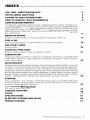
INDEX _______________________
THE 1988 "LIMITED WARRANTY" . ............. .
OFTEN ASKED QUESTIONS ............. .
LISTING OF AREA DISTRIBUTORS .
HOW TO IDENTIFY YOUR SNOWMOBILE . . . . . . .
4
6
8
9
CONTROLS/INSTRUMENTS
Throttle lever, brake lever, ignition switch, headlamp dimmer switch, emergency cutout switch/ tether cut-out switch, rewind starter handle, primer, adjustable C'Tn.n.- .... ,
handle, speedometer,
gauge, injection oil level pilot lamp,
high beam pilot lamp, tank cap,
fuel level gauge, hood opening, tool bag,
spark plug holder, fuse holder, spare drive belt holder, fuel shut-off valve, rear bumper, accessories . . . . . . . . . . . . . . . . . . . . . . . . . .
10
BREAK .. JN PERIOD
Engine and belt break-in, 10 hour-inspection, inspection check Jist
17
FUEL & OIL
recommended oil, oil injection system
Recommended
PRE-START CHECK
Check points
STARTING PROCEDURE
Manual
before riding, emergency starting
LUBRICATION
Frequency, steering and front suspension mechanism, drive axle, countershaft (disk
system,
brake and driven pulley), slide suspension, chaincase oil level, oil
rotary valve system .
. ....... .
MAINTENANCE
Maintenance chart, belt guard removal, drive belt removal and installation, drive belt
condition, new drive
brake condition, brake adjustment, spark plugs, suspension
condition,
track condition/ track tension and alignment,
drive pulley, drive chain tensionner, steering and front suspension mechanism, steering
and ski legs camber adjustment, muffler attachment, engine head nuts, engine mount
screws, air filter, carburetor adjustment, high altitude kit, oil injection system, cooling
system, headlamp beam aiming, bulb replacement, general inspection ... _ ...
STORAGE
Track, suspension, skis, controls, chaincase, drive pulley, countershaft (disk brake
and driven pulley), cooling system/ engine and primer lubrication, fuel tank and carburetors, chassis, general inspection .
. ....................... .
PRE-SEASON PREPARATION
Pre-season preparation chart ..
TROUBLE SHOOTING
TOOLS
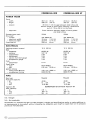
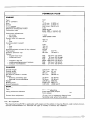
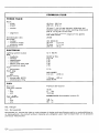
SPECIFICATIONS .
50
51
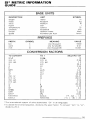
Sl METRIC INFORMATION GUIDE
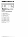
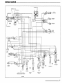
WIRING DIAGRAM
55
57
19
20
21
23
29
42
47
48
3
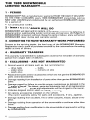
TtiE 1988 SNOWMOBILE
LIMITED WARRANTY _ _ _ _ _ _ _ _ __
1 -PERIOD
BOMBARDIER® INC. as manufacturer, warrants FROM THE DATE OF DELIVERY
TO THE FIRST CONSUMER, every 1988 BOMBARDIER snowmobile, sold as
NEW AND UNUSED, and predelivered by an authorized BOMBARDIER dealer
for a period of:
• 12 consecutive months.
2- WHAT BOMBARDIER WILL DO
BOMBARDIER will repair and/or replace, at its option, components defective in
material and/or workmanship (under normal use and service), with a genuine
BOMBARDIER component without charge for parts or labour, at any authorized
BOMBARDIER dealer during said warranty period.
3 .. CONDITION TO HAVE WARRANTY WORK PERFORMED
Present to the servicing dealer, the hard copy of the BOMBARDIER Warranty
Registration card or proof of purchase received by the customer from the selling
dealer at time of delivery.
4 .. WARRANTY TRANSFER
This warranty is transferable to subsequent owner(s) for remainder of warranty
period from original date of delivery.
5 - EXCLUSIONS - ARE NOT WARRANTED
• Normal wear on all items such as, but not limited to:
-
drive belts
- bulbs
slider shoes
runners on skis
spark plugs
• Replacement parts and/or accessories which are not genuine BOMBARDIER
parts and/or accessories.
• Damage resulting from installation of parts other than genuine BOMBARDIER
parts.
• Damage caused by failure to provide proper maintenance as detailed in the
Operator's Manual. The labour, parts and lubricants costs of all maintenance
services, including tune-ups and adjustments will be charged to the owner.
• Vehicles designed and/or used for racing purposes.
• All optional accessories installed on the vehicle.
(The normal warranty policy for parts and accessories, if any, applies).
• Damage resulting from accident, fire or other casualty, misuse, abuse orneglect.
• Damage resulting from operation of the snowmobile on surfaces other than
snow.
• Damage resulting from modification to the snowmobile not approved in writing
by BOMBARDIER.
4
• Losses incurred by the snowmobile owner other than parts and labour, such
as, but not limited to, transportation, towing, telephone calls, taxis, or any
other incidental or consequential damage.
6- BATTERY WARRANTY:
• 12 consecutive months. (Pro-rated)
100o/o warranty coverage will start on the date the snowmobile was delivered
and run to the following April 30th. The remainder of the 12 month-period
will be pro-rated as follows:
- 50% from April 30th to December 1st.
-
40o/o from December 1st to December 31st.
30% from January 1st to end of warranty.
7 - EXPRESSED OR IMPLIED WARRANTIES
This warranty gives you specific rights, and you may also have other legal
rights which may vary from state to state, or province to province. Where
applicable this warranty is expressly in lieu of all other expressed or implied warranties of BOMBARDIER, its distributors and the selling dealer,
including any warranty of merchantability or fitness for any particular
purpose; otherwise the implied warranty is limited to the duration of this
warranty. However, some states or provinces do not allow limitations on
how long an implied warranty lasts, so the above limitation may not apply.
Neither the distributor, the selling dealer, nor any other person has been
authorized to make any affirmation, representation or warranty other than
those contained in this warranty, and if made, such affirmation, representation or warranty shall not be enforceable against BOMBARDIER or any
other person.
Some states or provinces do not allow the exclusion or limitation of incidental or consequential damages, so the above limitation or exclusion
may not apply.
BOMBARDIER INC. reserves the right to modify its warranty policy at
any time, being understood that such modification will not alter the warranty conditions applicable to vehicles sold while the above warranty is
in effect.
8- CONSUMER ASSISTANCE
If a servicing problem or other difficulty occurs, we suggest the following:
1. Try to solve the problem at the dealership with the Service Manager or Owner.
2. If this fails, contact your area distributor listed in the Operator's Manual.
3. Then if your grievance still remains unsolved, you may write to us:
Bombardier Inc.
Service Department
Recreational Products Division
Valcourt (Quebec), Canada JOE 2LO
September 1986
Bombardier Inc.
Valcourt (Quebec), Canada JOE 2LO
®*Trademarks of Bombardier Inc.
5
OFTEN ASKED
QUESTIONS __________________________
0: Why must my snowmobile be registered at the factory? After all I do have my
original invoice as proof of when I purchased my snowmobile.
A: Your warranty is va!td at any authorized dealer of the product. Your registration
is the key element in providing the servicing dealer with the necessary data to
complete warranty claim forms. This information is also used to notify owners
in the event of a safety recall.
0: Who should send the registration card to Bombardier Inc.?
A: The authorized dealer. However, it is important that the customer make sure
that it has been sent. The company might contact you should your vehicle be
recalled or in case of a particular warranty campaign.
0: I bought my snowmobile in O'King County but I snowmobile in Washington County. Can an authorized dealer in Washington County accept to perform warranty work
on my snowmobile?
A: Yes, any authorized dealer in North America can perform warranty repairs,
providing the customer warranty registration card is
0: Where can I find information on the lubrication and maintenance of my snowmobile?
A: In this Operator Manual provided with the vehicle at the time of delivery.
0: Will the entire warranty be void or cancelled, if I do not operate or maintain my
new snowmobile exactly as
in the Operator's Manual?
A: The warranty of the new snowmobile cannot be ~.~Voided/! or ucancelled'~
However, if a particular failure is caused by operation or maintenance other than
is shown in the Operator Manual, THAT failure may not be covered under warranty. This includes service work performed by the customer, especially the
critical adjustments to ignition, timing, carburation and oil injection/or oil mixture.
0: Would you give some examples of abnormal use or strain, neglect or abuse?
A: These terms are
and overlap each other in areas. Some specific examples may include: running the machine out of oil, chain fatlure caused by a
lack of lubrication, operating the machine with a broken or damaged part which
causes another part to tali, and so on. If you have any specific questions on
operation or maintenance, please contact your authorized dealer for advice.
6
0: What costs are my responsibility during the warranty period?
A: The customer's responsibility includes all costs of normal maintenance services, non-warranty repairs, accidents and collision damage, as well as oils,
and spark plugs, and incidental or consequential damages costs as explained
in the warranty.
0: Are "Genuine" Bombardier replacement parts used in warranty repairs covered
by warranty?
A: Yes. When installed by an authorized dealer, any "Genuine" Bombardier part
used in warranty repairs assumes the remaining warranty that exists on the machine.
0: If I sell my snowmobile within the warranty period, will the new owner qualify
for the balance of the warranty?
A: Yes, provided the unit has already been registered with the manufacturer.
Note that the change of ownership card in this manual should be completed
and sent to Bombardier Inc.
0: How can I receive the best owner assistance?
A: The satisfaction and goodwill of the owners of Bombardier products are of
primary concern to your authorized dealer and Bombardier Inc. Normally, any
problems that arise in connection with the sales transaction or the operation of
your snowmobile will be handled by your Dealers Sales or Service Departments.
It is recognized, however, that despite the best intentions of everyone concerned,
misunderstandings wJ/1 sometimes occur. If you have a problem that has not
been handled to your satisfaction through normal channels, we suggest that
you discuss your problem with a member of dealership management. Frequently,
complaints are the result of a breakdown in communications and can quickly
be resolved by a member of the dealership management. If the problem already
has been reviewed with the Sales Manager or Service Manager, contact the
Dealer himself or the General Manager.
7
LISTING OF AREA
DISTRIBUTORS_ _ _ _ _ _ _ _ _ _ __
CANADIAN DISTRIBUTORS
AMERICAN DISTRIBUTORS
Quebec Branch
1350, Nobel
Boucherville (Quebec) J48 1A1
(514} 655-6121
Province of Quebec
BOMBARDIER CORPORATION
All States (excluding Alaska)
Ontario Branch
230, Bayview Drive
Barrie \Ontario) L4N 4Y8
(705) 728-8600
Province of Ontario
Technical office
P.O. Box 7060
Riverview (New Brunswick) E1B 1VO
(506) 386-6117
Atlantic Region
BROOKS EQUIPMENT LIMITED
1616,
Edward Street
P.O. Box
Winnipeg (Manitoba) R3C 2V8
(204) 633-7247
British Columbia, Manitoba, Saskatchewan,
Alberta, Yukon
CHARLES R. BELL LIMITED
Riverside Drive
P.O. Box 1050
Corner Brook (Newfoundland) A2H 6J3
{709) 634-3533
Newfoudland, Labrador
HUDSON'S BAY CO. LTD.
165, Hymus Blvd
Pointe-Claire (Quebec) H9R 1G2
(514) 630-5279
North-West Territories, Franklin District &
Keewatin
8
SERVICE OFFICES
East Main Street Road
Malone, New York 12953
(518) 483-4411
Techoical office
(506) 386-6117
Eastern Region
4505, West Superior Street
P.O. Box 16106
Duluth, Minnesota 55816-0106
(218) 628-2881
East-Central/ Central Region
- P.O. Box 1569
Idaho Falls, Idaho 83403
(208) 529-9510
Western Region
NATIONAL SALES OFFICE
O'Hare Lake Plaza
2350, Devon Avenue
Suite 150
Des Plaines, Illinois 60018
(312) 298-9540
MILLER EQUIPMENT AND RECREATIONAL
CENTER
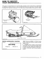
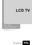
HOW TO IDENTIFY
YOUR SNOWMOBILE _ _ _ _ _ _ _ _ __
The main components of your snowmobile (engine, track and frame) are identified
by different serial numbers. It may sometimes become necessary to locate these
numbers for warranty purposes or to trace your snowmobile in the event of theft.
Track serial
number
Engine serial
number
A015002019
A009 005 002
Vehicle serial number
A015 007 023
Vehicle serial number meaning:
0000 00000
-,----
Model no
AOOO 000 013
I
Vehicle no
1988 Formula MX/MX LT /PLUS have
3732, 3734 and 3733 as model number
respectively.
0
NOTE: We strongly recommend
that you take note of all the serial
numbers on your vehicle and supply them
to your insurance company. It will surely help in the event your snowmobile is
stolen.
9
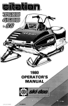
CONTROLS/
INSTRUMENTS _______________________
M
N
I
D
F
Q
c
A015 007 002
A ) Throttle Lever
B J Brake Lever
C J Ignition/Light Switch
D) Head/amp Dimmer Switch
E) Emergency Cut-out Switch
F J Tether Cut-out Switch
G J Rewind Starter Handle
H J Primer
I ) Adjustable Steering Handle
J J Speedometer
K J Tachometer
L J
Gauge
MJ Injection Otl Level Pilot Lamp
(red)
N) High Beam Pilot Lamp (blue)
0 J Tank Cap
P J Electric Fuel Level Gauge
0 J Hood Opening
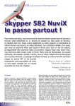
A) Throttle Lever
8) Brake Lever
Located on the right side of handlebar.
When compressed, it controls the engine
speed and the engagement of the transmission. When released, engine speed
returns automatically to idle.
Located on the left side of handlebar.
When compressed, the brake is applied.
When released, it automatically returns
to its original position. Braking effect is
proportionate to the pressure applied on
the lever and to the type of terrain and
its snow coverage.
1Q _________________________
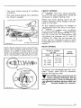
C) Ignition Switch
The lights are automatically ON whenever the engine is running.
OFF
toN
+OFF
&~
Upper position
before starting
Lower position
to stop engine
A017 006 004
A002 007 002
Key operated, three (3) position switch.
To start the engine, first turn key to ON
position. To stop the engine, turn the
key to OFF position.
The 3rd position is unused.
D) Headlamp Dimmer Switch
The dimmer switch, located on left side
of handlebar, allows correct selection of
headlamp beam. To obtain high or low
beam simply flick switch.
The driver of this vehicle should familiarize himself with the function of this
device by using it several times on first
outing. Thereby being mentally prepared for emergency situations requiring its
use.
+
+
WARNING: If the switch has been
used in an emergency situation
the source of malfunction should be
determined and corrected before restarting engine.
WARNING: For safety reasons,
the emergency cut-out switch is
easily accessible; be careful not to operate it inadvertently.
F) Tether Cut-out Switch
A pull switch located below the handlebar. Attach tether cord to wrist or other
convenient location then snap tether cutout cap over receptacle before starting
engine.
A008 006 003
E) Emergency Cut-out Switch
A push pull type switch located on the
right side of the handlebar. To stop the
engine in an emergency, push the button to the lower off position and simultaneously apply the brakes. To start engine, button must be at the upper ON
position.
If emergency engine "shut off" is required completely pull cap from safety
switch and engine power will be automatically shut ''off''.
0
NOTE: The cap must be installed
on the safety switch at all times in
order to operate the vehicle.
+
WARNING: If the switch is used
in an emergency situation the
source of malfunction should be determined and corrected before restarting engine.
11
G) Rewind Starter Handle
L) Temperature Gauge
Auto rewind type located on right hand
side of vehicle. To engage mechanism,
pull handle.
The gauge indicates engine coolant temperature. Normal operating temperature
is from 50° to 100°C (120° - 212°F)
H) Primer
A push-pull button located below handlebar. Pull and push button (2-3 times)
to activate primer. The primer should always be used for cold engine starts. After
engine is warm however, it is not necessary to use primer when starting.
I) Adjustable Steering Handle
- Remove steering pad.
A0l5 007 005
- Loosen the four (4) retaining screws.
However/ coolant
can vary
depending on driving condition. If coolant
exceeds 100°C (212 ° F)
reduce speed and run vehicle in loose
snow or stop engine immediately.
Adjust the handle to the desired position.
+
WARNING: Do not adjust too high
as the brake lever may contact
the windshield when turning.
- Lock the steering handle in
by
tightening the four (4) retaining screws
to 26 N •m (19 lbf•ft).
- Reinstall steering pad.
J) Speedometer
The speedometer is linked directly to the
drive axle. Direct-reading dial indicates
the speed of the vehicle.
Odometer records the total distance travelled in kilometers.
K) Tachometer
The tachometer registers the impulses
of magneto. Direct-reading dial indicates
the number of revolutions per minute
(RPM) of the engine.
-.r CAUTION: The tachometer is pro-
T tected by a fuse, if tachometer
stops operating check fuse condition
and if necessary replace. The fuse is
0.1 amp. Do not use a higher rated fuse
as this can cause severe damage to
the tachometer.
+
WARNING: To remove coolant
tank cap, place a cloth over the
cap and unscrew it to the first stop to
release the pressure. If this notice is
disregarded loss of fluid and possible
severe burns could occur.
M) Injection Oil Level Pilot
Lamp (Red)
Will light up when injection oil level is
low. Check level and replenish as soon
as possible.
-.r CAUTION: Do not run engine out
T of oil. Serious engine damage wiU
occur.
0
NOTE: Whenever brake lever is
compressed, oil injection level pilot lamp should light up. If not replace
lamp.
12-----------------------
N) High Beam Pilot Lamp
(Blue)
Tool Bag
Lights up when headlamp is on high
beam.
To gain access, tilt hood. Ideal location
for spare spark plugs, rope, first aid kit,
flashlight, etc.
0) Tank Cap
Spark Plug Holder
Unscrew to fill up tank then fully tighten.
..A. WARNING: Never use a lite match
T or open flame to check fuel level.
To keep spark plugs dry and prevent
shocks that might affect the adjustment
or break them, a holder is provided inside of hood, close to top of right shock
absorber.
..A. WARNING: Remove fuel tank cap
T slowly. Fuel may be under pressure and spray may cause fire and injuries.
Fully tighten them into the holder.
(TYPICAL)
P) Electric Fuel Level Gauge
The electric fuel gauge is located in the
dashboard and allows driver to observe
the fuel level while riding the snowmobile.
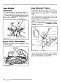
Q) Hood Opening
Pull down the latches to unlock the hood
from its anchors.
0
..A.
NOTE: Always lift hood gently up
until stopped by restraining device.
WARNING: It is dangerous to run
an engine with the hood opened,
unfastened or removed.
T
A015 008 003
Spark plugs
in holder
-------------------------- 13
Fuse Holder
Fuel Shut-off Valva
Tachometer
The tachometer is protected with 0. 1
ampere rated fuse. Fuse holder is located under the hood beside the tachometer. If it stops operating, check fuse condition and replace if necessary.
It is recommended to close it when transporting or storing vehicle. The valve is
under hood, on top of R.H. side footrest.
Two stoppers are provided on the fuel
shut-off valve to prevent the lever from
rotating due to vibrations.
These stoppers are set so that the inner
tip of the lever slightly contacts the stoppers while in the fully opened or fully
closed positions.
Tachometer
Valve
Stoppers
Spare Drive Belt Holder
A spare drive belt can be installed in clips
on belt guard.
R.H.
A015 007 007
footrest
When opening or closing valve, always
rotate lever so that it flips over the stopper and maintains its position.
14--------------------------
Fully closed
Fully opened
A015 008 004
A015 005 042
Fully open the valve in order to operate
the vehicle.
~ CAUTION: Always fully open the
T valve before riding. Never allow
the valve lever to remain between stoppers.
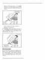
Rear Bumper
To install bumper in its lower position,
proceed as follows:
Lift snow guard and block in that position.
- From inside of tunnel, remove both
bumper retaining screws, each side
of vehicle.
The rear bumper can be installed in two
(2) positions as desired by the driver.
The low position can be useful when the
driver is digged in deep snow to give a
grip at a more convenient level.
High
position
Remove
screws
A015 005 025
Take bumper off.
-Reverse bumper position and fulfy insert into tunnel.
A015 005 041
--------------------------- 15
When installing bumper in its lower
position, the retaining screws have
to be relocated in different holes as
shown.
Screw position
for bumper
in low position
A0i5 007 024
- Firmly tighten bumper screws.
-Replace snow guard.
0
NOTE: When installing bumper at
its upper position, bumper retaining screws have to be relocated in different holes as shown.
Accessories
Some optional accessories might be added to your vehicle such as speedometer/ tachometer/ hitch, electric starter,
etc, if not standard on your vehicle. Ask
your authorized dealer for more information.
16--------------------------
BREAK-IN P E R I O D - - - - - - Engine
With Bombardier-Rotax snowmobile engines, a break-in period is required before running the vehicle at fu II throttle.
Engine's manufacturer recommendation
is ten ( 10) to fifteen ( 15) operating hours.
During this period, maximum throttle
should not exceed 3/4, however, brief
full acceleration and speed variations
contribute to a good break-in. Continued
wide open throttle accelerations, prolonged cruising speeds, and lugging are
detrimental during the break-in period.
0
NOTE: To assure additional protection during the initial engine breakin, 500 ml (18 imp. oz) of BLIZZARD Oil
(P/N 496 0135 00) or the same quantity of BOMBARDIER Injection Oil should
be added to gas for the first full gas tank
filling.
, . , CAUTION: Remove and clean
T spark plugs after engine break-in.
Belt
A new drive belt requires a break-in period of 25 km ( 15 miles).
10 - Hour Inspection
As with any precision piece of mechanical equipment, we suggest that after the
first ten ( 10) hours of operation or thirty
(30) days after the purchase, whichever
comes first, your vehicle be checked by
your authorized dealer. This inspection
will give you the opportunity to discuss
the unanswered questions you may have
encountered during the first hours of
operation.
The 10 hour inspection is at the
expense of the vehicle owner.
----------------------------17
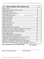
10 - HOUR INSPECTION CHECK LIST
Engine timing
Spark plugs condition: (remove and clean)
Carburetor adjustment
Oil injection pump adjustment
Engine head nuts
Drive pulley screw (torque)
Engine mount screws
Muffler attachment
Chaincase oil level
Drive chain tension
Injection system oil level
Rotary valve oil level
Engine coolant level
Brake operation and lining condition
Ski alignment {runners condition), ski leg camber adjustment
Steering arm, retorque to 25 N•m (18 lbf•ft)
Handlebar bolts, retorque to 26 N•m (19 lbf•ft)
Driven pulley preload
Pulley alignment and drive belt condition
Track condition, tension and alignment
Suspension, torque rear axle screw to 48 N•m (35 lbf•ft)
Lubrication (steering, suspension, drive axle, etc.)
~I
wiring, tighten all loose bolts, nuts and linkage
n of lighting system (HI I LO beam, brake light, etc.),
ation of emergency cut-out switch and tether cut-out switch
We recommend that you have your dealer sign this inspection.
D~te
of 10 hour inspection
Dealer signature
18 - - - - - - - - - - - - - -
./
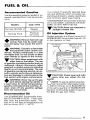
FUEL & OIL _ _ _ _ _ _ _ __
Recommended Gasoline
Use the specified gasoline, leaded or unleaded, available from most service stations.
MODEL
GAS TYPE
Formula MX/MX LT
Regular
Formula PLUS
190 octane)
It is a blend of specially selected base
oils and additives which provides outstanding lubrication, engine cleanliness
and minimum spark plug fouling.
If BOMBARDIER Snowmobile Injection
Oil is unavailable, substitute with BLIZZARD Oil (P/N 496 0135 00).
CAUTION: Never use outboard or
-., straight mineral oils.
..r
Premium
Oil Injection System
.A. WARNING: Remove fuel tank cap
T slowly. Fuel may be under pressure and spray may cause fire and injuries.
.A. WARNING: Gasoline is flammable
T and explosive under certain conditions. Always manipulate in a well
ventilated area. Do not smoke or allow
open flames or sparks in the vicinity.
CAUTION: Never experiment with
-., other fuels or fuel ratios. The use
of gasoline containing alcohol such as
methanol, ethanol (commonly called
gasohol) or similar products including
naphta is not recommended. The use
of gasoline containing alcohol can resultin vehicle performance deterioration and damage to critical parts in the
fuel system and engine components.
.A. WARNING: Never top up the gas
T tank before placing the vehicle in
a warm area. At certain temperatures,
gasoline will expand and overflow. Always wipe off any gasoline spillage
from the snowmobile.
Always maintain a sufficient amount of
BOMBARDIER Snowmobile Injection Oil
in the injection oil tank.
Oil injection
reservoir
..r
Recommended Oil
..r CAUTION: Check level and refill
-., every time you refuel. Do not
overfill.
NOTE: To assure additional protection during the initial engine breakin, 500 ml (18 imp. oz) of BLIZZARD Oil
or the same quantity of BOMBARDIER
Injection Oil should be added to gas for
the first full gas tank filling.
0
Use BOMBARDIER Snowmobile Injection Oil (P/N 496 0133 00- 1 liter) available from the authorized dealer. This
type of oil will flow at temperatures as
low as minus 40°C ( 40° F).
--------------------------- 19
PRE-START CHECK _ _ _ _ _ __
Check Points
• ACTIVATE THE THROTTLE CONTROL
LEVER SEVERAL TIMES to check that
it operates easily and smoothly. The
throttle control lever must return to
idle position when released.
• Check that the skis and the track are
not frozen to the ground or snow surface and that steering operates freely.
• Activate the brake control lever and
make sure the brake fully applies before the brake control lever touches
the handlebar grip.
..A. WARNING: Before removing the
T radiator pressure cap place a cloth
over the cap and unscrew it to the first
step to release the pressure. Never drain
or refill the cooling system when engine is hot. Loss of fluid and possibility of severe burns could occur, if this
notice is disregarded.
• Check injection oil level.
• Check fuel level.
• Ensure fuel shut-off valve is in fully
opened position.
• Check coolant level. Liquid should be
60 mm (2 318 in) lower than top of
radiator (engine cold).
Maximum level
60 mm (2 3/8 in)
from top
A015 007 007
• Verify that the path ahead of the vehicle is clear of bystanders and obstacles.
A015 002 021
If additional coolant is necessary or if
entire system has to be refilled, use a
solution of three (3) parts of antifreeze
for two (2) parts of water (60o/o antifreeze, 40o/o water). (See "Cooling System" in "Storage" section).
0
NOTE: Always use ethylene-glycol
antifreeze containing corrosion inhibitors specifically recommended for
aluminum engines.
20-------------------------
• Clean and check operation of the
head-light, taillight and brakelight.
..A. WARNING: Only start your snowT mobile once all components are
checked and functionning properly.
STARTING PROCEDURE _ _ _ __
Test throttle control lever operation.
Check that the emergency cut-out switch
is in the ON position.
t
ON
~
~
A
T
WARNING: If engine does not
shut-off when applying the emergency cut-out switch and or when pulling the tether cut-out cap, stop the engine by turning off the ignition key. Do
not operate the vehicle further, see an
authorized dealer.
Allow the engine to warm before operating at full throttle.
Emergency Starting
Should the rewind starter rope fray and
break, the engine can be started with
the emergency starter rope supplied with
the tool kit.
Upper position
before starting engine
A017 006 007
Ensure the tether cut-out cap is in position and that the cord is attached to
your clothing.
A
T
WARNING: Do not wind starting
rope around your hand. Hold rope
by the handle only.
Activate the primer two (2) or three (3)
times.
0
..W
NOTE: Primer is not necessary
when the engine is warm .
CAUTION: Use of ether and/or
other types of fluid as a starting
aid can cause damage to engine components and is not recommended.
T
Manual Starting
Insert the key in the ignition and turn to
ON position.
Grasp manual starter handle firmly and
pull slowly until a resistance is felt then
pull vigorously. Slowly release the rewind starter handle.
A
T
WARNING: Do not apply throttle
while starting.
Before Riding
Check operation of the emergency cutout switch and tether switch. Restart
engine.
A007 003 030
A
T
WARNING: Do not start the vehicle by the drive pulley unless it
is a true emergency situation. Have the
vehicle repaired as soon as possible.
Attach emergency rope to any available
handle and to the starter clip supplied
in the tool box. Wind the rope thightly
around drive pulley.
---------------------------21
0
NOTE: The spark plug socket can
be used as an emergency starter
grip.
A015 003 027
A003 003 016
Start engine as per usual manual starting.
A
WARNING: When starting the vehicle in an emergency situation
by the drive pulley, do not reinstall the
belt guard and return slowly to have
vehicle repaired.
T
22--------------------------
LUBRICATION _ _ _ _ _ _ _ __
The following symbols will be used to
show what type of lubricant should be
used at the suitable locations.
Chain lube
or
WD-40
AOOO 000 007
Usual
~ grease.gun
Frequency
Routine maintenance is necessary for
all mechanized products, and the snowmobile is no exception. A weekly vehicle inspection contributes to the life
span of the snowmobile.
It is recommended that the steering system and suspension be lubricated monthly or every forty (40) hours of operation.
If the vehicle is operated in wet snow or
in severe conditions these items should
be lubricated more frequently.
Penetrating lubricant is recommanded
on ball joints and moving parts. May be
used either:
-chain lube from BARDAHL (BCS 362,
dry)
- W0-40
AOOO 006 001
0
NOTE: When lubricating grease
fittings, grease until grease appears at joints. Always use low temperature grease (P/N 413 7061 00).
..A.. WARNING:
Only perform such
procedures as detailed in this
manual. It is recommended that dealer assistance be periodically obtained
on other components/systems not covered in this manual. Unless otherwise
specified, engine should be turned OFF
for all lubrication and maintenance
procedures.
T
..A.. WARNING: Do not lubricate throt-
T
tie and/or brake cables and hous-
ings.
Other grease fittings require low temperature grease (P/N 413 7061 00) using
usual grease gun.
----------------------------23
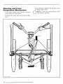
Steering and Front
Suspension Mechanism
Lubricate upper and lower control
arms and tie rod ends.
Coat stabilizer sliders with grease and
oil their ball joints.
0
Grease ski legs, ski pivots and idler
arm.
A015 006 003
24----------------------------
NOTE: There are thirty-three {33)
lubrication points.
'
·------r
A015 006 006
A015 006 004
----25
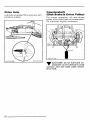
Drive Axle
Lubricate at grease fitting using low temperature grease.
Countershaft
(Disk Brake & Driven Pulley)
For proper operation/ disk and driven
pulley must slide freely on countershaft. ·
So lubricate slightly and evenly.
A015 003 010
r
, . , CAUTION: Do not lubricate exT cessively as the lubricant could
contact and soil brake pads and/or
drive belt.
26-------------------------
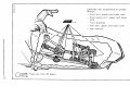
a-:
(I)
)>
~
Lubricate rear
at grease
(D
(I)
- front arm: upper and lower axle
front swing arm: upper and lower
axle
front shackles
fn
rear arm: upper and lower axle
-rear shackle
N
--.....1
0
NOTE: There are nine (9} grease
fittings.
c
fn
'C
(D
:I
cr:I
Chaincase Oil Level
Check the oil level by removing the oil
filler cap. Oil level must be within lower
and upper mark on dipstick with dipstick unscrewed. Refill as required using
BOMBARDIER chaincase oil (P/N 413
8019 00- 250 ml).
Oil injection
tank reservoir
Rotary Valve System
Check reservoir oil level frequently. Level should be kept as shown in plastic
reservoir. If necessary replenish to maximum oil level line using BOMBARDIER
Snowmobile Injection Oil available from
your authorized dealer.
0
NOTE: The chaincase oil capacity
is approximately 256 ml (9 imp.
oz).
Oil Injection System
Always maintain a sufficient amount of
BOMBARDIER Snowmobile Injection Oil
in the injection oil tank .
..r CAUTION: Check level and refill
T every time you refueL Do not
overfill.
A015 003 012
28----------------------
A015 003 013
MAINTENANC~E
_______________
The following Maintenance Chart indicates regular servicing schedules to be
performed by you or your authorized
dealer. If these services are performed
as suggested, your snowmobile will give
many years of use.
SERVICE AND
MAINTENANCE
CHART
+
WARNING: Only perform such
procedures as detailed in this
manual. It is recommended that an authorized assistance be periodically obtained on other components/systems
not covered in this manual. Unless
otherwise specified, engine should be
turned off for all lubrication and maintenance procedures .
.E
.E
0
0
0
=
?~E
>-~E
-Q)_!:/.
..CQ)_!:/.
~.._._..
~
~>o
Q) <I>
ON
0
:e.
Ln
t:>o
0 Q.)
....oco
o
.... E
0..!:/.
Q)
Ciio
CCI
Q)
0:-:::
>-N E
Q) >- 0
u'-0
cCI.>O
o>N
a>coM
C)
c.
0
......
a;
Q.)
cr.:
NOTE: The ten ( 10) hour inspection is a very important part of proper service
and maintenance.
-----------------29
Belt Guard Removal
A
T
WARNING: Engine should be running only when belt guard is secured in place.
1. Tilt the hood.
2. Pull out both retaining pins.
3. Lift and remove the belt guard.
4. Slip the belt out from the drive pulley and remove completely from the
vehicle.
A015 003 014
Retaining pins
Drive Belt Removal
and Installation
A
T
WARNING: Never start or run engine without the drive belt installed. Running an unloaded engine
is dangerous.
1. Tilt the hood and remove the belt
guard.
2. Open the driven pulley by twisting
and pushing the sliding half. Hold in
fully open position.
A015 003 015
To install the drive belt, reverse the procedure, however pay attention to the following.
The maximum drive belt life span is obtained when the belt has the proper rotation direction. Install it so the printed
information on the belt can be read
when facing pulleys.
CORRECT
~
BOMBARDIER
BOMBARDIER
FABRKlU~ AU CANADA
FASRIOU~ AU CANADA
MAOEINCAf-A- - - - - -
3. Slip the belt over the top edge of the
fixed half.
30--------------------------
Identification
FACING PULLEYS
A001 003 002
+
WARNING: Brake pads must be
replaced when fixed pad projects
only 1 mm (1/32 in) from caliper. Replacement must be performed by an
authorized dealer.
Identification
FACING PULLEYS
A001 003 003
"1IIF CAUTION:
Do not force or use
~ tools to pry the belt into place,
as this could cut or break the cords in
the belt.
Drive Belt Condition
Inspect belt for cracks, fraying or abnormal wear {uneven wear, wear on one
side, missing cogs, cracked fabric). If
abnormal wear is noted, probable cause
could be pulley misalignment, excessive R. P.M. with frozen track, fast starts
without warm-up period/ burred sheave,
oil on belt or distorted spare belt. Contact your authorized dealer.
Check the drive belt width. Replace it
if less than 31.9 mm (1 1/4 in).
A008 006 002
New Drive Belt
Brake Adjustment
When installing a new drive belt, breakin period of 25 km ( 15 miles) is strongly recommended.
The brake mechanism is a self-adjusting
type. If a quicker brake response is desired, strongly squeeze the brake lever
several times, this will actuate the self
adjusting mechanism.
Brake Condition
The brake mechanism on your snowmobile is an essential safety device.
this mechanism in proper working condition. Above all, do not operate the
snowmobile without an effective brake
system.
-------------------------31
Strongly
squeeze
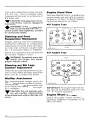
Overheated
(light grey) Normal
A008 006 002
Fouled
(black)
{brownish}
After the adjustment, brake should apply fully when lever is approximatively
13 mm ( 112 in) from handlebar grip. It
not, do not tamper with the brake, contact your servicing dealer.
AOOO 004 010
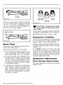
, . , CAUTION: If spark plug condition
T is not ideal, contact your authorized dealer.
Check spark plug gap using a wire feeler gauge. It should be 0.4 mm (.016 in).
Reinstall plugs and connect wires.
Suspension Condition
Check all front suspension components
for excessive play or wear including ball
joints, control arms and links etc.
A008 006 002
Spark Plugs
Disconnect the spark plug wires and remove the spark plugs.
Check the condition of the plugs.
• A brownish tip reflects ideal conditions. (Carburetor adjustments, spark
plug heat range, etc., are correct).
• A black insulator tip indicates fouling caused by: carburetor idle speed
mixture and/or high speed mixture
too rich, incorrect fuel mixture ratio/
wrong type of spark plug (heat range),
or excessive idling.
• A light grey insulator tip indicates a
lean mixture caused by: carburetor
high speed mixture adjusted too
lean, wrong spark plug heat range,
incorrect fuel mixture ratio, or a leaking seal or gasket.
Visually inspect all rear suspension components including slider shoes, springs,
wheels, etc.
NOTE: During normal driving,
snow will act as a lubricant and
coolant for the slider shoes. Extensive
riding on ice or sanded snow will create
excessive heat build-up and cause premature slider shoe wear.
0
Suspension Adjustments
Shock Absorber Spring Preload
The rear suspension has two (2) preload
adjustments:
32-------------------------
The front shock spring for surface
condition.
The rear shock spring (twin shocks)
for drive(s weight.
FRONT SPRING
0
NOTE: The front shock absorber
of the rear suspension should be
removed to adjust spring collar.
When the front spring cam is at the
lowest elevation more weight is distributed on the skis.
At the highest position the weight is
transferred from the skis to the track.
NOTE: For deep snow condition
or hill climbing, it is recommended
to place the front spring cam at position
four (4) or five (5). For hard surface riding place it at position one (1), two (2)
or three (3). Also, the rear bumper position can be changed to give a more
accessible grip (refer to ,,Controllnstruments").
0
Driver's weight
A015 005 041
Surface condition
Each shock a bsorbar has a five (5) position cam located at the bottom of the
shock. If a stiffer or softer action is desired, the spring preload may be increased or decreased by adjusting the cam.
REAR SPRING
Driver's weight
kg (lb)
from
up to
64 (140}
73 (160)
82 (180)
64 (140)
73 (160)
82 (180)
Came
position
1
2
3
4- 5
To adjust, use the adjustment key supplied. Spray some WD-40 between
spring and spring collar.
,.,. CAUTION: There must be two (2)
~ thrust washers between spring
and spring collar. If any is missing, do
not attempt to adjust spring collar and
see an authorized dealer for installation.
----------------------------33
Fit the key on the shock spring collar
and turn clockwise for stiffness or counterclockwise for softness.
A014 001 001
To summarize, the choice of cam positions depends on operator's weight, riding speed and field condition.
Cam
position
1
Operator's
weight
Light
Riding
speed
Low
Field
condition
Flat
2
3
4
screw
A015 005 039
As a guideline here are the preferred positions:
5
-...
Heavy
-
High
Bumpy
A slight suspension bottoming occuring
in the worst riding conditions indicates
to the operator a good choice of preload
adjustment (cam position).
Optional springs with different rates are
available for your convenience. Ask an
authorized dealer for information.
Limiter Screw
The function of the suspension limiter
screw is to control the transfer of vehicle weight during acceleration. The
closer the nut from the cotter pin, the
more the weight will be transferred to
the track to provide a better traction.
The farther the nut from the cotter pin,
the lesser the weight will be transferred
to the track, thus maintaining a more
positive direction. Limiter screw allows
to adjust weight transfer according to
driver's requirement, field and/or snow
conditions.
34--------------------------
Snow
condition
Nut position
related
to cotter pin
Hill climbing
Close
Hard surface
Farther
Track Condition
Lift the rear of the vehicle and support
it off the ground. With the engine off
rotate the track by hand, and inspect
condition. If worn or cut, or if track fibers are exposed, or if missing or defective inserts or guides are noted; contact an authorized dealer.
, . , CAUTION: Too much tension will
... result in power loss and excessive
stresses on suspension components.
I
+
WARNING: Do not operate a
snowmobile with a cut, torn or
damaged track.
Track Tension and Alignment
If necessary to adjust; loosen the rear
idler wheel retaining screws and the adjuster bolt lock nuts, then loosen or tighten the adjuster screws located on the
inner side of the rear idler wheels. If correct tension is unattainable, contact an
authorized dealer.
NOTE: Torque retaining screw to
48 N•m (35 lbf•ft) after adjustment.
0
Tension:
0
NOTE: Ride the vehicle in snow
about fifteen (15) - twenty (20)
minutes prior to adjusting track tension.
Lift the rear of vehicle and support with
a mechanical stand. Allow the suspension to extend normally and check gap
half-way of slider shoe. The gap should
be 30 mm (1 3116 in) between the slider shoe and the bottom inside of the
track when applying a downward pull of
7.3 kg (16 Ib). If the track tension is too
loose, the track will have a tendency to
thump.
0
NOTE: Track tension and alignment
are inter-related. Do not adjust one
without the other.
Alignment
Start the engine and accelerate slightly
so that track turns slowly. Check that
the track is well centered; equal distance on both sides between edges of
track guides and slider shoes.
30 mm (1 3/16 in)
with 7.3 kg {16 lbl
A014 004 021
-------------------------35
(TYPICAL)
0
Equal distance
NOTE: Torque retaining screw to
48 N•m (35 lbf•ft} after adjust-
ment.
(TYPICAL)
Torque to
48 N•m (35 blf•ftl
Guides
Restart engine, rotate track slowly and
recheck alignment.
Drive Pulley
A014 005 022
These vehicles are equipped with the
TRA drive pulley {Total Range Adjustable). This pulley includes three {3) calibration screws that provide the opportunity to perform minor adjustments to
the clutch in order to keep the engine
at it's peak power R.P.M., thereby maintaining optimal vehicle performance.
A001 055 011
.A. WARNING: Before checking track
T alignment, ensure that the track
is free of particles which could be
thrown out while it is rotating. Keep
hands, tools, feet and clothing clear
of track. Ensure no-one is standing in
close proximity to the vehicle.
To correct, stop the engine, loosen the
rear idler wheels retaining screws then
loosen the lock nuts and tighten the adjuster screw on side where the slider
shoe is the farthest to the track insert
guides.
Guide
Slider
shoes
The clutch is factory adjusted at position three (3) to provide the best performance under most riding conditions
at sea level. However certain conditions,
such as deep snow, high altitude, pulling a load, etc. may allow the engine
to run below it's peak power R.P.M. at
wide open throttle thus decreasing the
vehicle performance. Should such conditions be encountered the calibration
screws can then be resets to allow the
engine to operate at it's peak power
R.P.M. (given in technical data as max.
HP R.P.M.).
Guide
Tighten on this side
A001 005 011
Tighten lock nuts and the idler wheel
retaining screws.
The adjustment may be set at any one
of six (6) positions, numbered from one
( 1) to six (6). Note that for casting purposes numeral one ( 1) appears as a
dot. Each of these positions provides
an increase or a decrease, in numerical
order, of the engine speed by approximately 200 R.P.M.
36----------------------------
Example:
(Vehicle at sea level during full acceleration in normal conditions).
Adjustment screw
Engine speed
Position no 2
7800 R.P.M.
Position no 3
8000 R.PM.
{standard position)
Position no 4
8200 R.PM.
Positions two (2) and four (4) allow the
engine to run below or above it's power peak reducing vehicle performance.
NOTE: One must bear in mind that
the purpose of these calibration
screws is to maintain the engine R.P.M.
at it's peak power, a lower or upper
speed will actually result in less vehicle
performance.
The point of maximum power, in the
1988 Formula PLUS, occurs at 8000
R.P.M. while the maximum permissible
engine speed (red line) is 9000 R.P.M.
0
Adjustment Procedure
To change the calibration screw position, back off its locking nut and change
the position of the calibration screw
head. The notch on the screw head
must be aligned with the desired numeral position. See illustration.
, . , CAUTION: Back off the calibraT tion screw locking nut only far
enough to allow a change of position
of the screw head. Never attempt to
remove the locking nut or the calibration screw. Make sure the adjustment
is set at the same position for all three
(3) screws.
+
0
+
WARNING: The drive pulley must
be inspected and cleaned by an
authorized dealer at least annually.
Drive Chain Tensioner
Run vehicle forward so that true freeplay can be taken. To adjust, remove
the hair pin from adjusting screw. Fully
tighten adjusting screw by hand then
back off only far enough for hair pin to
engage in locking hole.
WARNING: Always retorque locking nut to 10 N•m (89 lbf•in).
-------------------------37
This initial adjustment should provide
3-5 mm ( 1/8 13/64 in) free-ploy when
measured at the outer circumference of
the brake disk.
,... CAUTION: Free-play must not exT ceed 5 mm (13/64 in), readjust if
necessary.
WARNING: If the specified freeplay is not reached with the tensioner screw fully tightened, consult
an authorized dealer.
+
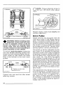
Engine Head Nuts
With the ENGINE COLD, check that the
engine head nuts are tight and equalfy
torqued to 20 N•m (15 lbf•ft). Respect
tightening sequence as follows:
467 Engine Type
Steering and Front
Suspension Mechanism
Inspect steering and front suspension
mechanism tightness of components
(steering arms control arms and links,
tie rods, ball joints, ski coupler bolts
etc.). If necessary replace or retighten.
Check the condition of the skis and the
ski runners. Replace if worn.
+
WARNING: Excessively worn skis
and/or ski runners will hinder
proper vehicle control.
537 Engine Type
Front
Steering and Ski Legs
Camber Adjustment
There are accurate adjustments to perform on this vehicle and they should be
done only by an authorized dealer.
Muffler Attachment
The engine/exhaust system parts are
vital toward efficient muffler function.
Check all attachments and muffler ball
joint.
the springs and/or tighten if necessary.
,... CAUTION: Do not operate vehiT cle with muffler disconnected
otherwise serious engine damage will
occur.
38 _________________________
IMPORTANT: The engine head nut torque should be checked after the first
five (5) hotJrs of operation.
Engine Mount Screws
Check the engine mount screws for
tightness. Retighten if necessary to 25
N•m (18 lbf•ft).
Air Filter
Leaving the vehicle uncovered during a
snowfall or riding in deep powder snow
may block the air filter.
,.,. CAUTION: Make sure both carT buretors start to operate simultaneously.
Lift hood and remove air filter from air
intake silencer.
A
A002 002 009
A016 oo2 012
A) Air Screw Adjustment
Completely close the air screw (until a
slight seating resistance is felt) then
back off screw:
467 engine type: 1 112 turn
537 engine type: 1 turn
Air intake silencer
Clean the filter by shaking the snow out
of it, dry it out.
Check that the air box is clean and dry
and reinstall the filter.
,.,. CAUTION: These vehicles have
T been calibrated with the filter install~d. Operating the vehicle without
it will cause damage to the engine.
Reinstall properly.
Carburetor Adjustment
,.,. CAUTION: Never operate your
T snowmobile with the air intake
silencer disconnected. Serious engine
damage will occur if this notice is disregarded.
B) Idle Speed Adjustment
Turn idle speed screw clockwise until
it contacts the throttle slide then continue turning two (2) additional turns. This
will provide a preliminary idle speed setting. Start engine and allow it to warm
then adjust idle speed to 1800-2000
R.P.M. by turning the idle speed screw
clockwise or counterclockwise.
,.,. CAUTION: Do not attempt to set
T the idle speed by using the air
screw. Severe engine damage can occur. If idle speed is unattainable contact your authorized dealer.
----------------------------39
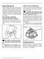
High Altitude Kit
Snowmobiles used in high altitude areas
( 1200 m (4000 ft) and up) are subjected to lose power, about 3o/o per 300
m ( 1000 ft) of elevation increase. The
carburetor and power train have to be recalibrated to meet those particular requirements. Ask your authorized dealer
for more information on high altitude kit
availability.
Oil Injection System
Injection Oil Filter Condition
Inspect oil filter at least once a month.
Insure that filter is not obstructed by foreign particles; if so, see an authorized
dealer.
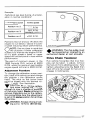
Injection Pump Adjustment
Proper oil injection pump adjustment is
very important. Any delay in the opening of the pump can result in serious
engine damage.
, . , CAUTION: The carburetor must
T be adjusted before adjusting the
oil injection pump. Make sure idle
speed is 1800-2000 R.P.M.
To check adjustment eliminate the throttle cable free-play by pressing the throttle lever until a slight resistance is felt
then hold in place. The aligning marks
on the pump casting and lever must
align perfectly. If not/ contact an authorized dealer.
NOTE: Injection- pump should be
adjusted by your authorized dealer.
0
(TYPICAL)
Aligning
marks
, . , CAUTION: An obstructed injecT tion oil filter will cause oil starvation resulting in serious engine damage.
0
NOTE: After a storage period, it is
important that your dealer replace
the injection oil filter and that he verifies the oil flow of the injection pump.
40--------------------------
A015 002 017
Cooling System
Check condition of hoses and clamps
tightness. Using a hydrometer check
that the antifreeze solution is strong
enough for the temperature in which
the vehicle is operated.
0
NOTE: Should the coolant temperature raise above recommended range 50 100°C (120 212°F) hose
off grime from the heat exchanger (underneath the frame above the track).
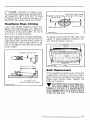
Headlamp horizontal
center line
light beam (high beam
projected on the wall)
Headlamp Beam Aiming
The angle of the headlamp beam has
been pre-adjusted prior to delivery.
Should you wish readjustment, place the
vehicle on a flat surface 381 em ( 12 ft
6 in) from a wall or screen
With the suspension correctly adjusted,
the rider seated on the vehicle and the
high beam ON check that the center of
high intensity zone of high beam is 25
mm { 1 in) below horizontal line of headlamp height.
Light beam center
A002 004 007
To adjust, remove the four (4) caps, turn
upper or lower adjusting screws to obtain desired beam position.
Headlamp center line
c:e.r
+
]f
!0 l1
~
381 em (12ft 6 in)
~~~~!l
25 mm (1 in)
below headlamp center
A002 004 010
Aoo7 oo4 oo2
screw
Bulb Replacement
If the headlamp bulb is burnt, tilt hood,
unplug the connector from the headlamp. Remove the rubber boot and unfasten bulb retainer clips. Detach the
bulb and replace.
,.,. CAUTION: Never touch glass porT tion of an halogen bulb with bare
fingers, it shortens it's operating life.
If by mistake glass is touched clean it
with a glass cleaner that will not leave
a film on the bulb.
----------------------------41
If taillight bulb is burnt, expose the bulb
by removing the red plastic lens. To remove, unfasten the two (2) screws .
•
"1111111111111
WARNING: Always check light
operation after bulb replacement.
General Inspection
A002 004 009
Retainer clips
Check the electrical wiring and components, retighten loose connections.
Check for stripped wires or damaged insulation. Thoroughly inspect the vehicle and tighten loose bolts, nuts and
linkage. Inspect skis and ski runners for
wear.
STORAGE ____________________
It is during summer, or when a vehicle
is not in use for any length of time that
proper storage is a necessity. Storage
of the snowmobile during long periods
of inactivity consists of checking and
replacing missing, broken or worn parts:
Proper lubrication and treatment to insure that parts do not become rusted;
cleaning items such as carburetor, to
prevent gum and varnish formation within the carburetor; and in general, preparing the vehicle so that when the time
comes to use the snowmobile again it
will be in top condition.
•
WARNING: Only perform such
"1111111111111 procedures as detailed in this
manual. It is recommended that dealer assistance be periodically obtained on other components/systems not
covered in this manual. Unless otherwise specified, engine should be turned OFF. For all lubrication and maintenance procedures.
Track
Inspect the track for wear, cuts, missing track guides and broken rods. Make
any necessary replacement.
42---------------------------
•
WARNING: Do not operate a
snowmobile with a cut, torn or
damaged track.
"1111111111111
Lift the rear of vehicle until track is clear
of the ground then support with a
brace or trestle. The snowmobile should
be stored in such a way that the track
does not stay in contact with the cement floor or bare ground.
0
NOTE: The track should be rotated periodically, (every forty (40)
days). Do not release track tension.
...,. CAUTION: To prevent track damT age, temperature in the storage
area must not exceed 38°C (100°F).
Suspension
Remove any dirt or rust. Grease at all
grease fittings. Wipe off surplus. Replace worn slider shoes.
Skis
Wash or brush all dirt or rust accumulation from the skis and springs. Grease
at all grease fittings.
+
WARNING: Check the condition
of the skis and ski runners. Replace if worn more than half.
Controls
Lubricate the steering mechanism. Inspect all components for tightness,
(spring coupler bolts, steering arm locking bolts, tie rods, ball joints, etc.}.
Tighten if necessary. Oil moving joints
of the brake mechanism.
+
WARNING: Do not lubricate the
throttle and/or brake cables and
housings. Avoid getting oil on the
brake pads.
Coat all electrical connections and
switches with a greaseless metal protector. If unavailable, use petroleum jelly.
Chaincase
Drain the chaincase and refill to proper
level, using fresh chaincase oil. (P/N
413 8019 00- 250 ml). To drain, remove the chaincase cover.
0
NOTE: Chaincase oil capacity is
about 256 ml (9 fl. oz).
Drive Pulley
Inspection and cleaning must be performed by an authorized dealer at the
end of each season.
Countershaft
(Disk Brake & Driven Pulley)
For proper operation, disk and driven
pulley must slide freely on countershaft.
So lubricate slightly and evenly.
, . , CAUTION: Do not lubricate exT cessively as the lubricant could
contact and soil brake pads and/or
drive belt.
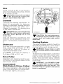
Cooling System
The engine cooling system should be
drained and refilled with a new coolant
mixture before each storage period.
+
WARNING: Never drain or refill
the cooling system when engine
is hot.
To drain the cooling system, siphon the
coolant mixture from the coolant tank,
using a primer pump and a length of
plastic hose and steel tubing inserted
as
as possible into the lower hose
of the tank.
+
WARNING: Use PRIMER PUMP
to siphon the coolant mixture.
Do not siphon with your mouth. The
coolant mixture is poison and can be
fatal is swallowed.
----------------------------43
Refill tank slowly until coolant overfills at bleed hole.
- Reinstall bleed screw.
Coolant
tank
537 Engine Type
Primer pump
5 L (1
gaU-el"'~\
11,
A015 002 010
When the coolant level is low enough,
remove the engine bleed screw and lift
the rear of vehicle to drain the heat exchangers.
CAUTION: To prevent rust forT mation in the cooling system, always replenish the system with the
recommended solution (60% antifreeze 40% water). Pure antifreeze
without water produces premature
freezing. Always use ethylene-glycol
antifreeze containing corrosion inhibitors specifically recommended for aluminum engines.
To refill the cooling system:
Put back the rear of vehicle on the
ground.
Continue to pour the coolant in the tank
until level reaches 60 mm (2 318 in) below top of radiator (engine cold).
-..r
467 Engine Type
With the coolant tank cap still removed start the engine and let it warm up
to reach its operating temperature and
thermostat open. Allow it running a few
minutes more.
44--------------------------
Stop engine and check coolant freezing point with a suitable tester. Coolant
must be strong enough for the temperature in which the vehicle is operated.
Inlet
~hoy
Check coolant level and add liquid if required. Put back the tank cap.
WARNING: Before removing the
cap place a cloth over the coolant tank and release the cap to the
first step to release the pressure. Loss
of fluid and possibility of severe burns
could occur, if this notice is disregard-
~~
t
•
T
ed.
{Oblique
coupling)
Outlet
hose
Aooz oo2 oos
(Straight
coupling)
5. Plug inlet primer hose to prevent
gasoline from draining.
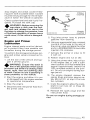
Engine and Primer
Lubrication
Engine internal parts must be lubricated to protect them from possible rust
formation during the storage
To perform the storage procedures (engine and primer valve) proceed as follows:
1. Lift the rear of the vehicle and support it off the ground.
•
WARNING: Ensure the track is
free of ails particles which could
be thrown out while it is rotating. Keep
hands, tools, feet and clothing clear
of track. Ensure no one is standing in
close proximity to the vehicle.
T
2. Start the engine and allow it to run
at idle speed until the engine reaches
its operational temperature.
3. Stop the engine.
4. Disconnect the inlet primer hose from
the primer valve.
6. Using an appropriate hose/ connect
one end of the hose to the inlet of
the primer valve and place the other
end in a BOMBARDIER Snowmobile
Injection Oil container.
7. Activate the primer in order to fill
it with oil.
8. Restart engine and run at idle.
9. Using the primer valve~ inject oil until the engine dies or until a sufficient quantity of oil has entered the
engine {approximately twenty-five
(25) complete strokes of the primer). Do not run engine during storage period.
10. The engine stopped, remove the
sparks plugs and pour approximately 85 ml (3 fl. oz imp.) of oil into
the cylinders.
11. Crank the engine to allow the crankshaft to turn two {2) or three (3)
revolutions.
12. Reinstall the spark plugs and the
inlet primer hose.
Do not run engine during storage period.
--------------------------45
~CAUTION: Plastic alloy com po-
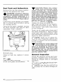
Fuel Tank and Carburetors
T nents such as fuel tank, windshield, controls, etc., can be cleaned
using mild detergents or isopropyl alcohol and a soft clean cloth. Never
clean plastic parts with strong detergent, degreasing agent, paint thinner,
acetone, etc. Never clean RIM Metton
hood with cleaners or products containing chlorine. Do not apply isopropyl alcohol directly on decals.
Remove the cap then using a syphon,
remove the gasoline from tank.
+
WARNING: Gasoline is flammable and explosive under certain
conditions. Always manipulate in a
well ventilated area. Do not smoke or
allow open flames or sparks in the vicinity.
Carburetors must be dried out completely to prevent gum formation during
the storage period.
Inspect the hood and repair any damage. Clean the frame. For the unpainted aluminum portion use only ''Aluminum cleaner'' and follow instructions
on the container.
Once the fuel tank is emptied, remove
the float chamber drain plug on each
carburetor. Drain carburetor.
Touch up all metal spots where paint
has been scratched off. Spray all bare
metal parts with metal protector. Wax
the hood and the painted portion of the
frame for better protection.
0
NOTE: Apply wax on glossy finish only. Protect the vehicle with
a cover to prevent dust accumulation
during storage.
~ CAUTION: If for some reason the
Aoo2 oo2 o1 o
T snowmobile has to be stored outside it is necessary to cover it with
an opaque tarpaulin. This caution will
prevent the sun rays and the grime
from affecting the plastic components
and the vehicle finish.
+
PI ug
Reinstall plug.
Check all fuel lines, replace if necessary.
General Inspection
Check the electrical wiring and components, retighten loose connections.
Check for stripped wires or damaged
insulation.
Chassis
Clean the vehicle thoroughly/ removing
all dirt and grease accumulation.
Thoroughly inspect the vehicle and tighten loose bolts, nuts and linkage.
0
riod.
46--------------------------
NOTE: Leave the drive belt off the
pulleys for the entire storage pe-
PRE-SEASON
PREPARATION ________________________
To simplify the pre-season preparation
we have drawn up a small chart. The
chart indicates servicing points to be
performed by you and your authorized
dealer. If these services are performed
as suggested, your vehicle will give
many hours of fun.
PRE-SEASON
PREPARATION CHART
IMPORTANT: Observe all warnings and
cautions mentioned throughout this
manual which are pertinent to the item
being checked. When component conditions seem less than satisfactory, replace with genuine BOMBARDIER parts
or suitable equivalents.
TO BE PERFORMED BY DEALER
•
TO BE PERFORMED BY OWNER
0
Change spark plugs*
Check chaincase oil level
Check drive chain tension
Check rotary valve oil level
Replace fuel filter (filter is located inside fuel tank)
Clean air filter
Refill gas tank
Check track condition, tension and alignment
Check and lubricate suspension
Inspect drive belt and install
Check throttle cable for free operation
Check steering, ski legs camber adjustments and ski runners condition
Inspect condition of starting rope
Check tightness of all bolts, nuts and links
Check coolant condition and level
Inspect seals for possible cuts or leaks
•
••
•••
•
0
0
Inspect brake condition and operation
Replace injection oil filter
Refill injection oil tank
Adjust oil injection pump
Set engine timing
Check pulleys, verify components and clean
0
•
0
0
0
Check electrical wiring
Adjust carburetors
0
0
0
0
0
0
0
0
0
0
0
*NOTE: Before installing new spark plugs, it is suggested to burn excess
storage oil by starting the engine, using the old spark plugs. Only perform
this operation in a well ventilated area.
---------------------------47
TROUBLE
SHOOTING __________________________
0
NOTE: The possible causes have been listed in an order of frequency. Therefore, items should be checked out in the same order as mentioned in the
trouble shooting guide.
SYMPTOMS
POSSIBLE CAUSES
WHAT TO DO
Engine turns over but
fails to start or starts
with difficulty.
1. No fuel to the engine
Check the tank level. Check for passible clogging of fuel line, item 4.
2. Flooded engine
Remove wet spark plug, turn ignition to OFF and crank engine several times. Install clean dry spark plug.
Start engine following usual starting
procedure. If engine continues to
flood, see your authorized dealer.
3. Spark plug/ignition
Check that emergency cut-out
switch is at the upper position (ON)
and the tether cut-out switch cap is
snapped over the receptacle.
Check for fouled or defective spark
plug. Disconnect spark plug wire,
unscrew plug and remove from cylinder head. Reconnect wire and
ground exposed plug on engine
cowl, being careful to hold away
from spark plug hole. Follow engine starting procedure and check
for spark. If no sparks appear, replace spark plug. If trouble persists,
contact your authorized dealer.
4. Clogged fuel line
(water or dirt)
Change fuel filter if necessary. Check
condition and connections of fuel
lines. Check the cleanliness of fuel
tank.
5. Carburetor
Contact your authorized dealer for
repair.
6. Too much oil in fuel
Oil Injection Pump system:
See an authorized dealer for pump
adjustment
Gas and Oil mixed in tank:
Drain the fuel tank and refiff with the
correct gas/oil mixture.
7. Engine timing
48----------------------------
Engine timing may be incorrect or
out of adjustment Contact your authorized dealer.
POSSIBLE CAUSES
WHAT TO DO
8. Engine compression
Running with a lean fuel mixture
may produce excessive engine wear
resulting in poor engine compressian. lf this occurs, contact your authorized dealer at once.
Engine does not turn
manually.
1. Seized engine
In the case of a seized
tact your authorized
Engine lacks
acceleration or power.
1. Fouled or defective spark
Check item 3 of "Engine turns over
but fails to start or starts with difficulty".
SYMPTOMS
Engine continually
backfires.
Snowmobile cannot
reach full speed.
plug
con-
2. Clogged fuel line
(water or dirt)
Check fuel line condition. (See item
4 of "Engine turns over but fails to
start or starts with difficulty").
3. Carburetor
Contact your authorized dealer.
4. Ignition
First check item 3 of "Engine turns
over but fails to start or starts with
difficulty'' If the ignition system
still seems faulty, contact your authorized dealer.
5. Engine
If unable to locate specific symptoms, contact your authorized
dealer.
1. Faulty spark plug
Check item 3 of "Engine turns over
but fails to start or starts with difficulty".
2. Overheated
Carburetor set too lean, contact
your authorized dealer.
3. Engine timing incorrectly set
Contact your authorized dealer.
1. Drive Belt
Check for damaged or worn drive
belt. Replace if necessary.
2. Incorrect track adjustment
Check track tension and alignment.
Readjust to :::.1-'t:!Lificatiu'lS (See
Maintenance
3. Engine
Check item 1 to 5 of "Engine lacks
acceleration or power".
4. Pulley misaligned
Contact your authorized dealer.
---------------------------49
TOOLS ______________________
As standard equipment each new snowmobile is supplied with basic tools such
as screwdriver,
emergency starter rope, etc.
Standard Tools
B
c
D
E
F
H
A015 001 002
A. Screwdriver
B. Socket 10/13 mm
c. Open End Wrench 10/13 mm
D.
Socket Wrench Handle
E.
Starter Rope
50----------------------------
F.
Socket 21/26 mm
G. Spring Collar
Adjustment Key
H. Emergency Starter Clip
SPECIFICATIONS _ _ _ _ _ _ __
FORMULA MX
FORMULA MX LT
467
2
69.5 mm (2.736 in)
61.0 mm
{2.402 in)
462.8 cm3 (28.24 in3)
7.5:1
7000 R.P.M.
PTO: Mikuni VM 34-352
MAG: Mikuni VM 34·353
467
2
69.5 mm (2. 736 in)
(2.402 in)
61.0 mm
462.8 em3 (28.24 in3)
7.5:1
7000 R.P.M.
Mikuni VM 34-352
Mikuni VM 34-353
1 1/2 turn
1800-2000 R.P.M.
1 1/2 turn
1800-2000 R.P.M.
455 ml
16 oz
455 ml
16 oz
4.2 L
148 oz
142 oz
60/40
43°C
90 kPa
4.2 L
148 oz
142 oz
60/40
43°C
90 kPa
ENGINE
Type
No of cylinders
Bore
Stroke
Displacement
Compression ratio {corrected)
Maximum horsepower R.P.M.*
Carburetor type
Carburetor adjustment:
air screw
idle speed
Rotary valve oil reservoir:
- Sl
Imp.
Cooling system capacity:
Sl
Imp.
-u.s.
Antifreeze/water mixture (% by volume)
Thermostat
Radiator pressure cap
Torque:
engine head nuts
- crankcase nuts
magneto ring nut
- crankcase/engine support screws
exhaust manifold bolts
(110°F)
(13 lb/in 2 )
M8:
20 N•m (15 lbf•ftl
M6:
9 N•m (80 lbf•in)
M8:
20 N•m (15 lbf•ftl
M22: 100 N•m (74 lbf•ft)
M8:
25 N•m (18 lbf•ft)
M8:
21 N•m (15 lbf•ft)
(110°F)
(13 lb/in 2 )
M8:
20 N•m (15 lbf•ftl
M6:
9 N•m (80 lbf•in)
M8:
20 N•m (15 lbf•ft)
M22: 100 N•m (74 lbf•ft)
M8:
25 N•m (18 lbf•ft)
M8:
21 N•m (15 lbf•ft)
CHASSIS
Overall length
Overall width
Overall height
Ski stance (center to center}
Torque:
steering arm/ski leg bolt
steering column/handlebar
Weight
Bearing area
Ground pressure
271.8 em
104.1 em
99 em
92.1 em
(107 in)
(41 in)
(39 in)
(36.25 in)
271.8 em
104.1 em
99 em
92.1 em
(107 in)
(41 in)
(39 in)
(36.25 in)
25 N•m
26 N•m
222.3 kg
5968 cm 2
3.72 kPa
(18 lbf•ft)
(19 lbf•ft)
(490 lb)
(925 in 2 l
(.530 lb/in 2 )
25 N•m
26 N•m
240 kg
7626 em 2
3.15 kPa
118 lbf•ft)
(19 lbf•ft)
(529 lb)
(1182 in 2 )
(.448 lb/in 2 )
BRAKE
Type
Lining minimum thickness
Control lever adjustment
Disc, self-adjusting
Fixed pad must projects 1 mm (1/32 in)
minimum from caliber.
13 mm {1/2 in) minimum distance from handlebar
grip when fully applied.
N.A.: Not applicable
*The maximum horse R.P.M. is applicable with engine on the vehicle. It may be different under certain circumstances and Bombardier Inc. reserves the right to modify it without any obligation.
51
FORMULA MX
FORMULA MX LT
38.1 em
290 em
41.9 em
315 em
POWER TRAIN
Track:
width
- length
- tension
-
alignment
Standard gear ratio
Drive belt:
number
maximum width
minimum width
Chaincase oil
(15 in)
(114 in)
(16.5 in)
(124 in)
30 mm (1 3/16 in) gap between slider shoe and
bottom inside of track when exerting a downward
pull of 7.3 kg (16 lb) to the track.
Equal distance between edges of track guides
and slider shoes.
22/44
22/44
414 5823 00
(1 3/8 in)
35 mm
32 mm (1 1/4 in)
256 ml {9 oz}
414 5823 00
35 mm (1 3/8 in}
32 mm (1 1/4 in)
256 ml {9 oz)
ELECTRICAL
Lighting system (output}
Bulb:
- headlamp
- tail/stop
speedometer
tachometer
electric fuel level gauge
- temperature gauge
Fuse:
- tachometer
Spark plug:
-type
gap
Ignition timing:
timing mark (8.T.O.C.)
stroboscopic timing
12
v
160
w
12
v
160
60/60 w
5/21 w
60/60 w
5/21 w
5W
5W
2W
2W
5W
5W
2W
2W
0.1 A
0.1 A
w
(.016 in)
NGK BR9ES
0.4 mm (.016 in)
2.51 mm (.099 in)
6000 R.P.M.
2.51 mm (.099 in)
6000 R.P.M.
Regular
Regular
40.9l
40.9 L
9
9
NGK BR9ES
0.4 mm
FUEL
Gas type
Fuel tank capacity:
Sl
Imp.
u.s.
Injection Oil
Tank capacity:
Sl
Imp.
-u.s.
gal.
10.8 gal.
gal.
10.8 gal.
BOMBARDIER Snowmobile Injection Oil
2.9 L
102 oz
98 oz
2.9 l
102 oz
98 oz
Hal.: Halogen
N.A.: Not applicable
Bombardier Inc. reserves the right to make changes in design and specifications and/or to make additions to,
or improvements in its product without imposing any obligation upon itself to install them on its products
previously manufactured.
62--------------------------
FORMULA PLUS
ENGINE
Type
No of cylinders
Bore
Stroke
Displacement
Compression ratio (corrected)
Maximum horsepower R.P.M.*
Carburetor type
Carburetor adjustment:
- air screw
idle speed
Rotary valve oil reservoir:
Sl
Imp.
Cooling system capacity:
- Sl
Imp.
-u.s.
Antifreeze/water mixture 1% by volume)
Thermostat
Radiator pressure cap
Torque:
engine head nuts
crankcase nuts
- magneto ring nut
- crankcase/engine support screws
- exhaust manifold bolts
537
2
72.0 mm (2.835 in)
64.0 mm (2.520 in)
521.2 cm 3 (31.81 in3)
6.5:1
8000 R.P.M.
PTO: Mikuni VM 40-29
MAG: Mikuni VM 40-30
1 turn
1800-2000 R.P.M.
455 ml
16 oz
4.2 L
148 oz
142 oz
60/40
42°C
90 kPa
{107°F)
(13 lb/in 2 )
M8:
20 N•m 115 lbf•ft)
M6:
9 N•m (80 lbf•in)
M8:
20 N•m (15 lbf•ft)
M22: 100 N•m (74 lbf•ft)
M8:
25 N•m (18 lbf•ft)
M8:
21 N•m (15 lbf•ft}
CHASSIS
Overall length
Overall width
Overall height
Ski stance (center to center)
Torque:
- Steering arm/ski leg bolt
- steering column/handlebar
Weight
Bearing area
Ground pressure
271.8 em
104.1 em
99 em
92.1 em
(107 in)
(41 in)
(39 in)
(36.25 in)
25 N•m
26 N•m
226.8 kg
6348 cm 2
3.57 kPa
(18 lbf•ft)
(19 lbf•ft)
(500 lb)
(984 in2)
(.508 lb/in2)
BRAKE
Type
Disc, self-adjusting
Lining minimum thickness
Fixed pad must projects 1 mm (1/32 in)
from caliper.
Control lever adjustment
13 mm ( 1/2 in) minimum distance from
handlebar grip when fully applied.
N.A.: Not applicable
*The maximum horse A.P.M. is applicable with engine on the vehicle. It may be different under certain circumstances and Bombardier Inc. reserves the right to modify it without any obligation.
----------~----------------63
FORMULA PLUS
POWER TRAIN
Track:
-width
length
41.9 em (16.5 in)
290 em (114 in)
-tension
30 mm (1 3/16 in) gap between slider shoe and
bottom inside of track when exerting a downward
pull of 7.3 kg Obi to the track.
-alignment
Equal distance between edges of track guides
and slider shoes.
Standard gear ratio
Drive belt:
number
maximum width
- minimum width
Chaincase oil
20/38
414 5823
35 mm
32 mm
256 ml
00
(1 3/8 inl
(1 1/4 in)
(9 oz)
ELECTRICAL
Lighting system (output)
Bulb:
- headlamp
- tail/stop
speedometer
- tachometer
el.ectric fuel level gauge
temperature gauge
Fuse:
tachometer
Spark plug:
type
gap
Ignition timing:
timing mark (B.T.O.C.l
stroboscopic timing
12
v
160
w
60/55 W HAL
5/21 w
5W
5W
2W
2W
0.1 A
NGK BR9ES
0.4 mm
(.016 in)
1. 75 mm (.69 in)
6000 R.P.M.
FUEL
Gas type
Fuel tank capacity:
- Sl
Imp.
-u.s.
Injection Oil
Tank capacity:
Sl
-Imp.
-u.s.
Premium (90 octane)
40.9 L
9
gal.
10.8 gal.
BOMBARDIER Snowmobile Injection Oil
2.9 L
102 oz
98
oz
Hal.: Halogen
N.A.: Not applicable
Bombardier Inc. reserves the right to make changes in design and specifications and/or to make additions to,
or improvements in its product without imposing any obligation upon itself to install them on its products
previously manufactured.
54----------------------------
Sl* METRIC INFORMATION
GUIDE _____________________________
BASE UNITS
DESCRIPTION
length
mass
force
liquid
temperature
pressure
torque
speed
UNIT
meter
kilogram
Newton
liter
Celsius
kilopascal
Newton meter
kilometer per hour
SYMBOL
m
kg
N
I
oc
kPa
N•m
km/h
PREFIXES
PREFIX
kilo
centi
milli
SYMBOL
k
c
m
MEANING
one thousand
one hundredth
one thousandth
VALUE
1000
0.01
0.001
CONVERSION FACTORS
TO CONVERT
lbf•ft
imp. oz
imp. gal.
in
in
ft
MPH
in2
in3
imp. oz
U.S. oz
imp. gal.
U.S. gal.
oz
lb
lbf
lbf•in
lbf•ft
lbf/in2
Fahrenheit
Celsius
TOt
lbf•in
U.S. oz
U.S. gal.
mm
em
m
km/h
cm 2
cm 3
ml
ml
I
I
g
kg
N
N•m
N•m
kPa
Celsius
Fahrenheit
MULTIPLY BY
12
0.96
1.2
25.4
2.54
0.3
1. 61
6.45
16.39
28.41
29.57
4.55
3.79
28.35
0.45
4.4
0.11
1.36
6.89
(a F 32) + 1.8
(°C X 1.8) + 32
"The international system of units abbreviates "SI" in all languages.
tTo obtain the inverse sequence, divide by the given factor. To convert "mm" to "in",
divide by 25.4.
--------------------------56
WIRING DIAGRAM _ _ _ _ _ __
COLOUR CODE
BK
WH RD
BL YL
BLACK
WHITE
RED
BLUE
YELLOW
GN
GY
VI
OR
BR
-
GREEN
GREY
VIOLET
ORANGE
BROWN
..A.. WARNING: Ensure all terminals
T are properly crimped on the wires
and all connector housings are properly fastened.
LOCATION OF CONNECTOR HOUSINGS
(REFER TO DIAGRAM)
C-1 .
C-2:
C-3:
C-4:
C-5:
C-6:
C-7:
C-8:
C-9:
C-1 0:
C-11 ·
C-12:
C-13:
C-14:
C-15:
C-16:
C-17:
C-18:
C-19:
At engine, right side
At engine, right side
At engine, right side
Between seat and fuel tank
On ignition switch
On console, left side
Near steering column
Near
column
In cab, near
In cab, near instruments
In cab, near instruments
In cab, near instruments
In cab, near instruments
In cab, near instruments
In cab, near instruments
Near oil reservoirs
Between seat and fuel tank
On taillight
Near voltage regulator
56-------------------------
WIRING DIAGRAM _ _ _ _ _ _ _ _ _ _ _ _ _ _ _ _ _ _ _ _ _ _ _ _ _ _ __
IGNITION SWITCH
0
w
GENERATING COIL
r
(/)
r,..,,./,l
tt
ELIGHTING COIL
SPARK PLUGS
'
BKIYL
7!---:'BK~/YL
~C1 • rBBKrr:;~ti!'-;
L
~-L-L-L~I
BK
-
Yl/BK
~
~
..__ _____,
~
IGNITION
MODULE
0
C-3
VI
3
~
VI
t
YL!BK
----------.
~
z
0
:::>
z
:::>
C-6
BK/YL
liT'
BK/YL
w9~~1.5--2-C-·5------1-~BK:._, ~
BK/Yl
VI
BK
BK!YL~
~~L-t--------...!B~K!;!.IY.!:_L-,,;::"'::,.,
........
~
C-7
~W~H~,~~~·~·~~~~~~~~
IYL ~~ /1 L /'
~
.A
BK
~
WH '="'
o/
TEMPERATURE
SENSOR
_Jr.i1
-b!;!J1
BK
TETHER
CUT-OUT SWITCH
EMERGENCY
SWITCH
BRAKE LIGHT
SWITCH
IGNITION COIL
~
C-8
~
r-r--r-----t+--+---+----++--------___2.!:..._~lJ=
GY
r----t+--t---+----+-t----------__!!G~YN~I_)
BL
C-4
GY
GYNI
1'..±,
1-.!1.--l
~
SWITCH
DIMMER
(HIGH - LOW)
Bl
L
..LA7A. YL/BK
-~./
'---'-/e-/_:;;'~-=::..._-1.....~.\-.l\(:"~ Y
YLIBK
~
FUEL LEVEL
SENSOR
BK
BK
>
"
"' '>3
'"~
BULB
""' ""'
~.J.~{,
I
~
BULB
(10WJ
HIGH BEAM
FORMULA MX/MX LT: 60/60 W
FORMULA PLUS: 60/55 W HALOGEN
;;
-
i~'"
OIL LEVEL
INDICATING
LAMP
"'"'
~
?::
""'l
'-
if
FUEL LEVEL
GAUGE
BULB
12WJ
TEMPERATURE
GAUGE
HEADLAMP
57
CHANGE OF ADDRESS
OR O W N E R S H I P - - - - - - - - - - - Any change in address or ownership should be brought to the attention of the
manufacturer by completing and sending out the card below.
NOTICE TO ALL NEW OWNERS: Make sure to receive the warranty registration
card from the previous owner, when the ownership is transferred. Also enclose
a photocopy of this registration card when informing of a change of ownership.
~----------------------------CHANGE OF ADDRESS
VEHICLE IDENTIFICATION NUMBER
I I I I I I I I I I I
OLD ADDRESS:
NAME
CITY
APT
STREET
NO
STATE/PROVINCE
ZIP/POSTAL CODE
NEW ADDRESS:
NAME
STREET
NO
I
I
I
CITY
STATE/PROVINCE
APT
ZIP/POSTAL CODE
~~----------------------------CHANGE OF OWNERSHIP
VEHICLE IDENTIFICATION NUMBER
,
I I I I I I I I I I I
The ownership of this vehicle is transferred
FROM:
NAME
NO
CITY
STREET
STATE/PROVINCE
APT
ZIP/POSTAL CODE
TO:
NAME
NO
CITY
STREET
STATE/PROVINCE
APT
ZIP/POSTAL CODE
BOMBARDIER INC.
ATT.: WARRANTY DEPARTMENT
VALCOURT (QUEBEC)
CANADA
JOE 2LO
I
I
- - - - - - - - - - - - - - - - - - - - - - - - - - - - - - - - 1I
EJI
BOMBARDIER INC.
ATT.: WARRANTY DEPARTMENT
VALCOURT (QUEBEC)
CANADA
JOE 2LO