1
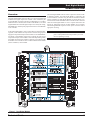
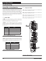
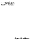
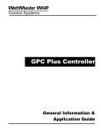
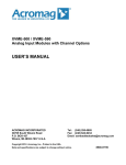
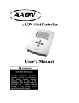
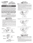
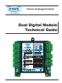
Factory Packaged Controls Coil Products Dual Digital Module Technical Guide Table of Contents OVERVIEW ........................................................................................................................................................ 3 Overview ......................................................................................................................................................................................3 INSTALLATION AND WIRING ........................................................................................................................... 4 Environmental Requirements .......................................................................................................................................................4 Mounting.......................................................................................................................................................................................4 Power Supply and Communications ............................................................................................................................................4 Important Wiring Considerations ..................................................................................................................................................5 VCM-S Modular Controller to Dual Digital Module Wiring ............................................................................................................6 VCM-X Modular E-BUS Controller to Dual Digital Module Wiring ................................................................................................8 START-UP AND COMMISSIONING.................................................................................................................. 10 General.......................................................................................................................................................................................10 Unit Configurations .....................................................................................................................................................................10 SEQUENCE OF OPERATION ........................................................................................................................... 11 Off Mode..................................................................................................................................................................................... 11 Cooling Mode ............................................................................................................................................................................. 11 Dehumidification Mode ............................................................................................................................................................... 11 Heat Pump Heating Mode (Air to Air) ......................................................................................................................................... 11 Defrost Mode .............................................................................................................................................................................. 11 Staging Delays ........................................................................................................................................................................... 11 TROUBLESHOOTING ...................................................................................................................................... 12 Using LEDs to Verify Operation..................................................................................................................................................12 LED Diagnostics .........................................................................................................................................................................13 Other Checks .............................................................................................................................................................................13 PART NUMBER CROSS REFERENCE TABLE PART DESCRIPTION ORION AAON COIL VCM-X Dual Digital Module OE370-23-DD-C 30311 VCM-X Modular Controller OE332-23-VCMX-MOD-C 30553 VCM-X Modular E-BUS Controller OE332-23E-VCMX-C VCM-X E-BUS Distribution Module OE365-23-EBD-C TBA 30312 VCM-X Expansion Module OE333-23-EM 30308 VCM-X 12 Relay Expansion Module OE358-23-12R 30309 www.aaon.com WattMaster Controls Inc. 8500 NW River Park Drive · Parkville , MO 64152 Toll Free Phone: 866-918-1100 PH: (816) 505-1100 · FAX: (816) 505-1101 · E-mail: [email protected] Visit our web site at www.orioncontrols.com WattMaster Form : AA-DDM-TGD-01F Copyright December 2013 WattMaster Controls, Inc. AAON® is a registered trademark of AAON, Inc., Tulsa, OK. Neither WattMaster Controls, Inc. nor AAON® assumes any responsibility for errors or omissions in this document. This document is subject to change without notice. Dual Digital Module Module Overview Overview The Dual Digital Module (OE370-23-DD-C) is a device that enables and modulates two digital compressors on HVAC Units controlled by the VCM-X Modular Controller (OE332-23-VCMX-MOD-C) or VCM-X Modular E-BUS Controller (OE332-23E-VCMX-MOD-C). The Dual Digital Module will control the digital compressors to satisfy the cooling, dehumidification, and heat pump requirements of the VCM-X Modular series controller. If the Dual Digital Module is in the Cooling Mode or Heat Pump Heating Mode, it will modulate the compressors to maintain the appropriate Supply Air Temperature Setpoint. If the module is in the Dehumidification Mode, it will modulate compressors to maintain the Coil Suction Temperature Setpoint. If the module is in the Heat Pump Heating Mode, the module can also monitor a signal for a Defrost Cycle from the VCMX Modular series controller if a Two Condenser Head Pressure Module (OE370-23-HP2C) is also installed. The Dual Digital Module must be used in conjunction with the VCMX Modular Controller. The Dual Digital Module is connected to the VCM-X Modular Controller using the E-BUS Distribution Module (OE365-23-EBD). The Dual Digital Module can also be directly connected to the the VCM-X Modular E-BUS Controller. Either connection allows the Dual Digital Module to receive setpoints and monitor the Supply Air Temperature from the VCM-X Modular series controller. The Dual Digital Module requires a 24 VAC power connection with an appropriate VA rating. NOTE: The Dual Digital Module contains no user-serviceable parts. Contact qualified technical personnel if your module is not operating correctly. Figure 1: Dual Digital Module Technical Guide 3 Dual Digital Module Installation and Wiring Environmental Requirements Power Supply and Communications The Dual Digital Module needs to be installed in an environment which can maintain a temperature range between -30°F and 150°F and not exceed 90% RH levels (Non-Condensing). The Dual Digital Module is connected to the E-BUS Distribution Module with a modular HSSC cable to provide communications from the VCM-X Modular Controller. The E-BUS Distribution Module uses WattMaster Control’s standard I2C modular cable to connect with the VCM-X Modular Controller, VCM-X Expansion Module, or 12-Relay Expansion Module. Mounting The Dual Digital Module is housed in a plastic enclosure. It is designed to be mounted by using the 3 mounting holes in the enclosure base. It is important to mount the module in a location that is free from extreme high or low temperatures, moisture, dust, and dirt. Be careful not to damage the electronic components when mounting the module. See Figure 2 for Module dimensions (dimensions are in inches). The Dual Digital Module can also be directly connected to the VCM-X Modular E-BUS Controller, bypassing the use of the E-BUS Distribution Module. The Dual Digital Module requires a 24 VAC power connection with an appropriate VA rating. WARNING: Observe polarity! All boards must be wired GND-to-GND and 24 VAC-to-VAC. Failure to observe polarity could result in damage to the boards. Figure 2: Dual Digital Module Dimensions 4 Technical Guide Dual Digital Module Installation and Wiring Important Wiring Considerations 4. Be sure that all wiring connections are properly inserted and tightened into the terminal blocks. Do not allow wire strands to stick out and touch adjoining terminals. This could potentially cause a short circuit. 5. Be sure all modular wiring harness connectors are seated firmly in their respective modular connectors on the circuit board. Please carefully read and apply the following information when wiring the Dual Digital Module: 1. The 1 to 5 VDC signals for the Copeland Compressor Speed need to use 18-gauge shielded twisted pair cable, and the Drain wire must be the GND signal. 2. All 24 VAC wiring must be connected so that all ground wires remain common. Failure to follow this procedure can result in damage to the module and connected devices. 3. All wiring is to be in accordance with local and national electrical codes and specifications. WARNING: OE370-23-DD-C Dual Digital Module COMP. #1 ENABLE R1 GND COMP. #2 ENABLE R2 NOT USED R3 NOT USED R4 RELAY COMMON RC +5V www.orioncontrols.com R2 R3 R4 Rc OE370-23-FD FULL DIGITAL COMPRESSOR MODULE +5V SIG 4 GND BIN 1 BIN 2 ADDRESS +5V SIG 2 GND COMPRESSOR #2 NOT USED COPELAND CNTRLR P6 COPELAND CNTRLR P5 +5V SIG 3 GND NOT USED +5V SIG 4 GND NOT USED BIN 1 BIN 2 COM NOT USED E-BUS Connector COMP. #1 CNTRLR C2 COMP. #2 CNTRLR C2 COMP. #1 & #2 CNTRLR C1 ANALOG AO1 AO2 GND AO1 AO2 GND AO1 AO2 GND P5 SHLD P4 P6 EXC P3 PWM1- C1 OUT P2 PWM1+ C2 COM P1 OE275-01 Suction Pressure Transducer RD WH BK PWM2- WattMaster Label #LB102056 Copeland Digital Compressor Controller A1 PWM2+ E-BUS Connector COMM 24 VAC GND PWR HSSC Cable HSSC Cable OE275-01 Suction Pressure Transducer ALARM STAT Connect To E-BUS Distribution Module or VCM-X Modular E-BUS Controller HVAC UNIT CONNECTIONS OPTIONS This Dip Switch Is Not Used For This Application COM COMPRESSOR #1 NOT USED COPELAND CNTRLR P6 COPELAND CNTRLR P5 GND GND +5V +5V SIG 1 GND +24 VAC SIG 3 COMPRESSOR A1 ENABLE COMPRESSOR A2 ENABLE COMPRESSOR B1 ENABLE COMPRESSOR B2 ENABLE RELAYS GND SIG 3 GND R1 R2 R3 R4 COMM R1 SIG 1 SIG 2 Be sure all controllers and modules are powered down before connecting or disconnecting HSSC cables. NOTE: ALL RELAY OUTPUTS ARE NORMALLY OPEN AND RATED FOR 24 VAC POWER ONLY - 1 AMP MAXIMUM LOAD RELAY CONTACT RATING IS 1 AMP MAX @ 24 VAC +5V SIG 1 GND NOTE: The Compressor Relays on the Dual Digital Module are used rather than the relay outputs on the VCM-X Modular series controller. This Dip Switch Is Not Used For This Application P5 SHLD P4 P6 EXC P3 C1 OUT P2 C2 COM P1 RD WH BK Copeland Digital Compressor Controller B1 Line Voltage WARNING!! Observe Polarity! All boards 24 VAC Transformer must be wired with GND-to-GND 3 VA Minimum and 24 VAC-to-24 VAC. Failure to observe polarity could result in Connect To Other damage to the boards. WattMaster-Approved E-BUS Expansion Module(s) Figure 3: Dual Digital E-BUS Connection Wiring Technical Guide 5 Dual Digital Module Installation and Wiring VCM-X Modular Controller to Dual Digital Module Wiring When using the VCM-X Modular Controller, the E-BUS Distribution Module is required ot connect to the Dual Digital Module. The Dual Digital Module connects to the E-BUS Distribution Module using a modular HSSC cable. The Dual Digital Module requires a 24 VAC power connection with an appropriate VA rating. For Stand Alone Applications, Connect To System Manager. For Network Applications Connect To Next Controller And/Or MiniLink PD On Local Loop. The E-BUS Distribution Module connects to the VCM-X Modular Controller, VCM-X Expansion Module, or 12 Relay Expansion Module using the I2C port. See Figure 4 below for wiring. Any E-BUS module can be connected to each of the four E-BUS Distribution Module’s output ports or can be daisy-chained together using HSSC cables. If using a spliced terminal connection for longer runs, one module can be connected to the E-BUS Distribution Module and any additional modules would be daisy-chained to the first module. For more information, refer to the E-BUS Distribution Module Technical Guide. OE332-23-VCMX-MOD-C VCM-X Modular Controller Note: All Relay Outputs Are Normally Open And Rated For 24 VAC Power Only. 1 Amp Maximum Load. Local Loop RS-485 9600 Baud R - 24VAC G - Fan ON/OFF Only All Comm Loop Wiring Is Straight Thru T to T, R to R & SHLD to SHLD Relay Output Contacts R2 Through R5 May Be User-Configured For The Following: 1 - Heating Stages 2 - See Note 1 Below 3 - Warm-up Mode Command (VAV Boxes) 4 - Reversing Valve (Air To Air Heat Pumps) 5 - Reheat Control (Dehumidification) 6 - Exhaust Fan Interlock 7 - Preheater For Low Ambient Protection 8 - Alarm 9 - Override 10 - Occupied 11 - OA Damper 12 - Heat Wheel 13 - Emergency Heat Note: 1.) When Using the HP2C Module, All Compressors Will Be Wired From the Protection Module, Not the VCM-X Controller. 2.) A Total Of 20 Relays Are Available By Adding Relay Expansion Modules. All Expansion Module Relay Outputs Are UserConfigurable As Listed Above. See Individual Component Wiring Diagrams For Detailed Wiring Of Analog Inputs And Outputs AI1 SET AI1 SET AI1 AI3 AI5 24 VAC AI4 SET AI2 SET AI7 AI3 SET AI4 AI2 SET AI2 AI5 SET GND GND Line Voltage AI7 SET AI3 SET 24VAC AI4 SET Size Transformer For Correct Total Load. VCM-X Controller = 8 VA Connect To E-BUS Distribution Module Jumpers AI5 SET Connect To Digital Room Sensor And/Or Digital CO2 Sensor Splice If Required AI7 SET OE271 Static Pressure Transducer Connect FRP Tubing To High Pressure Port (Bottom Tube) and Route To Static Pressure Pickup Probe Located In Unit Discharge. Leave Port Marked “Lo” Open To Atmosphere Line Voltage Connect To E-BUS Distribution Module or Expansion Module(s) (When Used) Warning: 24 VAC Must Be Connected So That All Ground Wires Remain Common. Failure To Do So Will Result In Damage To The Controllers. Figure 4: VCM-X Modular Controller Connection to Dual Digital Module 6 Technical Guide Dual Digital Module Installation and Wiring NOTE: Contact Factory for the correct HSSC cable length for your application. Cables are available in ¼, ½, 1, 2, 3, 4, and 5 Meter lengths and 100 and 150 Foot lengths. WARNING: Be sure all controllers and modules are powered down before connecting or disconnecting HSSC cables. OE370-23-DD-C Dual Digital Module OE365-23-EBD E-BUS Distribution Module +5V YS102308 REV 1 I2C TO COMM DIST. BOARD R1 SIG 1 R2 GND R3 OUTPUT +COMM SHLD +5V R4 SIG 2 Rc RELAYS GND -COMM GND ANALOG +5V +VDC AO1 SIG 3 AO2 GND GND INPUT +5V +COMM SHLD SIG 4 PWM1- GND PWM1+ BIN 1 PWM2- -COMM GND PWM2+ BIN 2 COM OPTIONS 24VAC ADDRESS GND PWR 485 DRV ALARM STAT COMM GND WARNING!! Observe Polarity! All boards must be wired with GND-to-GND and 24 VACto-24 VAC. Failure to observe polarity could result in damage to the boards. 24 VAC PWR WARNING!! Observe Polarity! All boards must be wired with GND-to-GND and 24 VAC-to-24 VAC. Failure to observe polarity could result in damage to the boards. Line Voltage Modular Cable Connect To VCM-X Modular Controller 24 VAC Transformer 3 VA Minimum HSSC Cable Connect To E-BUS Distribution Module HSSC Cable Connect To Other WattMaster-Approved E-BUS Expansion Module(s) Figure 4: VCM-X Modular Controller Connection to Dual Digital Module Technical Guide 7 Dual Digital Module E-BUS Controller to Dual Digital Module Wiring VCM-X Modular E-BUS Controller to Dual Digital Module Wiring Any E-BUS Module can be connected to the E-BUS Controller’s E-BUS port or can be daisy-chained together using HSSC cables. The Dual Digital Module directly connects to the VCM-X Modular EBUS Controller using a modular HSSC cable. The Dual Digital Module requires a 24 VAC power connection with an appropriate VA rating. See Figure 5 below for wiring. NOTE: Contact Factory for the correct HSSC cable length for your application. Cables are available in ¼, ½, 1, 2, 3, 4, and 5 Meter lengths and 100 and 150 Foot lengths. OE370-23-DD-C Dual Digital Module +5V R1 SIG 1 R2 GND R3 +5V R4 SIG 2 Rc RELAYS GND ANALOG +5V AO1 SIG 3 AO2 GND GND +5V SIG 4 PWM1- GND PWM1+ BIN 1 PWM2PWM2+ BIN 2 COM OPTIONS ADDRESS ALARM STAT COMM WARNING!! Observe Polarity! All boards must be wired with GND-to-GND and 24 VAC-to-24 VAC. Failure to observe polarity could result in damage to the boards. 24 VAC GND PWR Line Voltage 24 VAC Transformer 3 VA Minimum Connect To Other WattMaster-Approved E-BUS Expansion Module(s) HSSC Cable HSSC Cable Connect To VCM-X E-BUS Controller Figure 5: VCM-X Modular E-BUS Controller to Dual Digital Module Wiring Diagram 8 Technical Guide Dual Digital Module E-BUS Controller to Dual Digital Module Wiring WARNING: Be sure all controllers and modules are powered down before connecting or disconnecting HSSC cables. For Stand Alone Applications, Connect To System Manager. For Network Applications Connect To Next Controller And/Or MiniLink PD On Local Loop. Note: All Relay Outputs Are Normally Open And Rated For 24 VAC Power Only. 1 Amp Maximum Load. OE332-23E-VCMX-MOD-C VCM-X Modular E-BUS Controller Local Loop RS-485 9600 Baud RS-485 COMMUNICATION LOOP. WIRE “R” TO “R”, “T” TO “T” “SHLD” TO “SHLD” R - 24VAC RELAY CONTACT RATING IS 1 AMP MAX @ 24 VAC G - Fan ON/OFF Only RELAY COMMON All Comm Loop Wiring Is Straight Thru T to T, R to R & SHLD to SHLD FAN www.aaon.com RELAY 2 RELAY 3 RELAY 4 RELAY 5 Relay Output Contacts R2 Through R5 May Be User-Configured For The Following: 1 - Heating Stages 2 - Cooling Stages 3 - Warm-up Mode Command (VAV Boxes) 4 - Reversing Valve (Air To Air Heat Pumps) 5 - Reheat Control (Dehumidification) 6 - Exhaust Fan Interlock 7 - Preheater For Low Ambient Protection 8 - Alarm 9 - Override 10 - Occupied 11 - OA Damper 12 - Heat Wheel 13 - Emergency Heat Note: 1.) When Using the HP2C Module, All Compressors Will Be Wired From the Protection Module, Not the VCM-X Controller. Note: A Total Of 20 Relays Are Available By Adding Relay Expansion Modules. All Expansion Module Relay Outputs Are User Configurable As Listed Above. www.orioncontrols.com AAON No.: VCM-X MODULAR E-BUS CONTROLLER Orion No.:OE332-23E-VCMX-MOD-C AI1 = SPC (SPACE TEMPERATURE SENSOR) AI2 = SAT (SUPPLY AIR TEMPERATURE SENSOR) AI3 = RAT (RETURN AIR TEMPERATURE SENSOR) AI4 = OAT (OUTDOOR AIR TEMPERATURE SENSOR) AI5 = SUCTION PRESSURE SENSOR (FROM EXP. MODULE) AI7 = SPACE TEMPERATURE SENSOR SLIDE ADJUST OR VOLTAGE RESET SOURCE A01 = ECONOMIZER (2-10 VDC OUTPUT) A02 = SUPPLY FAN VFD (0-10 VDC OUTPUT) HSSC Cable Connect To VCM-X E-BUS Port E-BUS CONNECTOR ANALOG INPUT JUMPER SETTINGS AI1 SET See Individual Component Wiring Diagrams For Detailed Wiring Of Analog Inputs And LED BLINK CODES LED NAME STATUS1 STATUS2 NORMAL OPERATION 0 1 SAT FAIL 1 2 AI2 SET AI1 THERM 4-20mA 0-10V 0-5V OAT FAIL 2 2 AI2 THERM 4-20mA 0-10V 0-5V SPC FAIL 3 2 MODULE ALARM 4 MECH COOL FAIL 1 AI3 THERM 4-20mA 0-10V 0-5V THERM 4-20mA 0-10V 0-5V DIRTY FILTER AI4 AI5 THERM 4-20mA 0-10V 0-5V THERM 4-20mA 0-10V 0-5V PUSH BUTTON OVR AI7 2 3 FAN PROOF FAIL 3 3 4 3 EMERGENCY SHUTDOWN 5 3 LOW SAT 1 4 HIGH SAT 2 4 CONT. TEMP COOL FAIL 3 4 CONT. TEMP HEAT FAIL 4 1 4 5 ZONE OVR 2 5 OUTPUT FORCE ACTIVE 0 6 AI3 SET ANALOG INPUT JUMPER SETTINGS MUST BE SET AS SHOWN FOR PROPER OPERATION STATIC PRESSURE 2 3 MECH HEAT FAIL WattMaster Label #LB102073-01-A Rev.: 1A GND Line Voltage 24 VAC POWER ONLY WARNING! POLARITY MUST BE OBSERVED OR THE CONTROLLER WILL BE DAMAGED 2 IC EXPANSION 24VAC 2 IC DIGITAL SENSOR AI4 SET Size Transformer For Correct Total Load. VCM-X Controller = 8 VA Jumpers AI5 SET Splice If Required Connect To Digital Room Sensor And/Or Digital CO2 Sensor AI7 SET Connect To Expansion Module(s) (When Used) OE271 Static Pressure Transducer Warning: 24 VAC Must Be Connected So That All Ground Wires Remain Common. Failure To Do So Will Result In Damage To The Controllers. Connect FRP Tubing To High Pressure Port (Bottom Tube) and Route To Static Pressure Pickup Probe Located In Unit Discharge. Leave Port Marked “Lo” Open To Atmosphere Figure 5, cont.: VCM-X E-BUS Controller to Dual Digital Module Wiring Diagram Technical Guide 9 Dual Digital Module Start Up and Commissioning General In order to have a trouble free start-up, it is important to follow a few simple procedures. Before applying power for the first time, it is very important to run through a few simple checks. One of the most important checks to make before powering up the system for the first time is to make sure that the VCM-X Modular or VCM-X Modular E-BUS Controller is configured properly for your application. Refer to the VCM-X Controller Technical Guide or VCM-X Modular E-BUS Controller Technical Guide for more information. A handheld Modular Service Tool, Modular System Manager, or System Manager Touch Screen connected to the VCM-X Modular or VCM-X Modular E-BUS Controller will allow you to configure your application. Refer to the VCM-X Operator’s Interfaces Technical Guide or System Manager TS Technical Guide for more information. Check all wiring leads at the terminal block for tightness. Be sure that wire strands do not stick out and touch adjacent terminals. Confirm that all sensors required for your system are mounted in the appropriate location and wired into the correct terminals. WARNING: Observe polarity! All boards must be wired GND-to-GND and 24 VAC-to-VAC. Failure to observe polarity could result in damage to the boards. UNIT CONFIGURATIONS CIRCUIT A PERMUTATION CIRCUIT B HARDWARE VCM-X WSHP CONFIGURATION Comp A1 Comp A2 Comp B1 Comp B2 Relay 1 Relay 2 Relay 3 Relay 4 1 Fixed N/A Fixed N/A Use VCM-X Modular Series Controller Only 2 Compressors 2 Digital N/A Fixed N/A Use VCM-X Modular Series Controller Only 2 Compressors Digital Compressor 2 Compressors Dual Digital 3 Digital N/A Digital N/A Use VCM-X Modular Series Controller and Dual Digital Module 4 Fixed Fixed Fixed Fixed Use VCM-X Modular Series Controller Only 4 Compressors 5 Digital Fixed Fixed Fixed Use VCM-X Modular Series Controller Only 4 Compressors Digital Compressor Fixed Use VCM-X Modular Series Controller and Dual Digital Module 4 Compressors Dual Digital 6 Digital Fixed Digital Table 1: Unit Configurations Chart 10 Technical Guide Dual Digital Module Sequence of Operation NOTE: See Unit Configurations Chart on page 10 for more information about compressor staging. Off Mode Heat Pump Heating Mode (Air to Air) Heating Mode works the same as Cooling Mode except the Reversing Valve is switched and the sequence is opposite. Compressors modulate up when below the Heating Supply Air Setpoint and modulate down when above the setpoint. The Dual Digital Module will be in the Off Mode when no signal is being received from the VCM-X Modular series controller to run the compressors. Dehumidification Mode Cooling Mode In Dehumidification Mode, the compressor(s) will modulate to maintain the Suction Pressure Temperature Setpoint broadcast from the VCM-X Modular series controller. If there are two compressors, Compressor A1 will modulate up to 100% before Compressor B1 can be energized. If Compressor B1 is energized, Compressor A1 will be locked at 100%. When a Cool Signal is received, the Dual Digital Module will go into Cooling Mode. At this point, Compressor A1 will energize and modulate as necessary to maintain the Supply Air Temperature at the Active Supply Air Setpoint that is broadcast from the VCM-X Modular series controller. When Compressor A1 reaches 100%, a stage up timer is started. If Compressor A1 stays at 100% for the stage up timer, Compressor B1 will energize and both compressors will go to 50% and begin to modulate together. If there are additional fixed compressor stages and modulating Compressors A1 and B1 have modulated together up to 100%, then after a stage up delay, fixed Compressor A2 will stage on while A1/B1 go to 50% and begin to modulate from there. If A1/B1 again modulate up to 100%, then after a stage up delay, fixed compressor B2 will stage on while A1/B1 go to 50% and begin to modulate from there. Staging down will happen in the reverse order as just described if the Supply Air Temperature falls below the Supply Air Temperature Setpoint by the Cooling Stage Window value and the stage down timer has elapsed. After the fixed compressors have staged off, or if there are no fixed compressors, then the staging down of the digital compressors A1 and B1 will continue as follows. If Compressors A1/B1 modulate together down to 30% and the stage down timer elapses, Compressor B1 will deactivate and Compressors A1 will go to 60%. Compressors A1 will stage down if it is at 0% for the duration of the stage down timer. If there are additional fixed compressor stages and Compressor B1 has modulated up to 100%, then after a stage up delay, fixed Compressor A2 will stage on while B1 will again go to 50% and begin to modulate from there. If B1 again modulates up to 100%, then after a stage up delay, fixed compressor B2 will stage on while B1 will again go to 50% and begin to modulate from there. Stage down will again be the reverse as just described with Compressor A1 being the last compressor to stage off. Defrost Mode In Defrost Mode, if only Circuit A is energized, it will go to 100% and the reversing valve will deactivate. If both Circuit A & Circuit B are energized, they will both go to 100% and the reversing valve will be deactivated. The duration for Defrost Mode is determined by the VCM-X Modular series controller. NOTE: Defrost Mode is only available if a Two Condenser Head Pressure Module is installed. Staging Delays Staging Delays minimum run times and minimum off times are sent from the VCM-X Modular series controller. Technical Guide Revised: 12/16/13 11 Dual Digital Module Troubleshooting Using LEDs to Verify Operation The Dual Digital Module is equipped with LEDs that can be used to verify operation and perform troubleshooting. There are LEDs for communication, operation modes, and diagnostic codes. The module has seven LEDs—one used for power, one used for operation status, one used for alarms, and four used for the compressor relays. See Figure 6 for the LED locations. The LEDs associated with these inputs and outputs allow you to see what is active without using a voltmeter. The LEDs and their uses are as follows: Status LEDs Compressor LEDs “R1” - This LED will light up when Compressor A1 is enabled and will stay lit as long as Compressor A1 is active. “R2” - This LED will light up when Compressor A2 is enabled and will stay lit as long as Compressor A2 is active. “R3” - This LED will light up when Compressor B1 is enabled and will stay lit as long as Compressor B1 is active. “R4” - This LED will light up when Compressor B2 is enabled and will stay lit as long as Compressor B2 is active. “COMM” - The COMM LED lights up to indicate Communications between the module and the VCM-X Modular series controller. If Communications are established, the COMM LED will blink. “ALARM” - This is the diagnostic blink code LED. It will light up and blink out diagnostic codes. See Table 2 for Diagnostic Blink Code descriptions. The blink code descriptions are also located on the module’s front cover. No. of Blinks Status 0 No Problems 1 Low Suction Pressure Compressor A1 3 Low Suction Pressure Compressor B1 5 Pressure Sensor A1 Not Detected 7 Pressure Sensor B1 Not Detected 9 No Communication Table 2: ALARM LED Blink Codes “STAT” - This is the status blink code LED. It will light up and every 10 seconds will blink the status mode that the module is currently operating under. See Table 3 for Status Blink Code code descriptions. The blink code descriptions are also located on the module’s front cover. No. of Blinks Status 1 Off Mode 2 Cool Mode 3 Heat Mode 4 Dehumidify Mode 5 Defrost Mode Table 3: STAT LED Blink Codes Figure 6: LED Locations 12 Technical Guide Dual Digital Module Troubleshooting LED Diagnostics “PWR” LED: When the Dual Digital Module is powered up, the PWR LED (located below the address switches) should light up and stay on continuously. If it does not light up, check to be sure that the power wiring is connected to the board, the connections are tight, and the VCM-X Modular series controller is powered. If after making all these checks, the PWR LED does not light up, the module is probably defective. Other Checks NOTE: The Dual Digital Module contains no user-serviceable parts. Contact qualified technical personnel if your module is not operating correctly. “COMM” LED: The COMM LED lights up to indicate Communications between the module and the VCM-X Modular series controller. If the COMM LED does not blink, then communications have not been established. Check the connection between the VCM-X Modular Controller, the VCM-X Modular E-BUS Controller, the E-BUS Distribution Module, and the Dual Digital Module. “STAT” LED: As previously described, this LED will blink out the operation mode that the Dual Digital Module is operating under. When the board is first powered up, the STAT LED will do the following: Light up Blink out status code every ten seconds to indicate controller status “ALARM” LED: As previously described, this LED will blink on and off to indicate alarms and diagnostics. Technical Guide 13 Dual Digital Module Troubleshooting Temperature °F Pressure PSI Signal DC Volts See the OE275-01 Suction Pressure Transducer, Pressure, Temperature, and Voltage Chart for R410A Refrigerant testing (Table 4). The chart shows a temperature range from 20°F to 80°F. For troubleshooting purposes, the DC Voltage readings are also listed with their corresponding temperatures and pressures. Signal DC Volts Use the voltage column to check the Suction Pressure Transducer while connected to the Dual Digital Module. Read voltage with a meter set on DC volts. If the temperature/voltage or pressure/voltage readings do not align closely with the chart, your Suction Pressure Transducer is probably defective and will need to be replaced. Pressure PSI The Evaporator Coil Temperature is calculated by converting the Suction Pressure to Temperature. The Suction Pressure is obtained by using the OE275-01 Suction Pressure Transducer, which is connected into the Suction Line of the Compressor. OE275-01 Suction Pressure Transducer Coil Pressure – Temperature – Voltage Chart for R410A Refrigerant Temperature °F OE275-01 Suction Pressure Transducer Testing for R410A Refrigerant 21.19 80.94 1.8 59.03 168.10 3.2 24.49 87.16 1.9 61.17 174.32 3.3 27.80 93.39 2.0 63.19 180.55 3.4 30.99 99.62 2.1 65.21 186.78 3.5 33.89 105.84 2.2 67.23 193.00 3.6 36.80 112.07 2.3 69.24 199.23 3.7 39.71 118.29 2.4 71.15 205.46 3.8 42.30 124.52 2.5 72.95 211.68 3.9 44.85 130.75 2.6 74.76 217.91 4.0 47.39 136.97 2.7 76.57 224.14 4.1 49.94 143.2 2.8 78.37 230.36 4.2 52.23 149.42 2.9 80.18 236.59 4.3 54.50 155.65 3.0 56.76 161.88 3.1 Table 4: Coil Pressure/Voltage/Temp for OE275-01 Suction Pressure Transducers - R410A Refrigerant 14 Technical Guide Dual Digital Module Notes Technical Guide 15 www.aaon.com AAON Coil Products 203 Gum Springs Road • Longview, TX 75602-1721 Ph: (903) 236-4403 • Fax: (903) 236-4463 WattMaster Manual Form No: AA-DDM-TGD-01F