1
SEARS
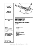
OWNER'S
MANUAL
Model No.
139.53225SRT1
139.53325SRT1
139.53425SRT1
139.53628SRT1
139.53629SRT1
139.53635SRT1
139.53637SRT1
139.53824SRT1
For Residential Use
Only
CRRFTSMRN®
GARAGE DOOR OPENER
• Safety Precautions
• Assembly
• Installation
Caution:
Read and follow all safety
rules and operating
Instructions before first
use of thls product.
Fasten the manual near
• Adjustment
• Care and Maintenance
• Operation
• Troubleshooting
• Parts List
the garage door after
Installation.
Complieswith UL 325 fll
regulationseffective
January1, 1993
_
Seam, Roebuck and Co., Hoffman Estates, IL 60179 U.S.A.
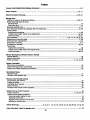
Contents
Page
A review of safety alert symbols................................. 2
You'll need tools.......................................................... 3
Safety information regarding garage door locks
and
rope_
............=,.....
°o,,
.. °.,,
o...o,
_°o
.......
balance...........
....................
.....
..............
..° ..........
Page
Installthe light and lens ................................................. 1
Attach emergency release rope and handle ................. 1
Electrical requirememts.............:................................... 2
Safety reversingsensor information............................. 21
°°..,°.°°o..,.°°°.,,3
Testing your garage door for sticking, binding
and
Contents
Install the safety reversing sensor........................... 22, 23
3
Illustrationof sectional door installation ..................... 4
Illustration of ooe-pie(_ door installation................... 5
Carton inventonj.......................................................... 6
Hardware inventory..................................................... 7
Assembly section - pages 8 - 11
Assemble T-rail ......................................................... 8
Attach cable pulley bracket ....................................... 8
Installtrolley .............................................................. 9
Fasten T-rail to opener ............................................. 9
Install chain/cabte ................................................... 10
Attach sprocket (xwer ............................................. 10
Tighten the chain and cable ................................... 11
Installation sactlon - pages 11 - 27
Installationsafety instructions................................. 11
Determine header bracket location
Sectional door ........ ;.............................................. 12
One-piece door ..................................................... 13
Install the header bracket ....................................... 14
Attach the T-rail to header bracket ......................... 15
Position the opener ................................................. 16
Hang the opener ..................................................... 17
Install the wall control ............................................. 18
Fasten door bracket (sectional door) ............................ 24
Fasten door bracket (one-piece door)........................... 25
Connect door arm to trolley (sectional door)................. 26
Connect door arm to trolley (one-piece door) ............... 27
Adjustment section - pages 28 - 30
Travel limit,adjustments................................................. 28
Force adjustments ................................................. .(......29
Test the safety reversil_gsensor ................................... 30
Test the safety reverse system .................................... 30
Operation safetyinstructions ........................................... 31
Care of your opener ......................................................... 31
Maintenance schedule .................................................... 31
Operation of your opener ................................................ 32
Receiver and remote controlprogramming .................... 33
Having a problem? ........................................... .........34, 35
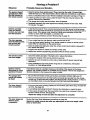
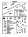
Repair parts, rail assembly .............................................. 36
Repair parts, installation...................... _........................... 36
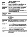
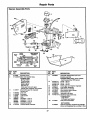
Repair parts, opener assembly ....................................... 37
Ac_essones...................................................................... 38
Index ................................................................................ 39
How to order repair parts................................................. 40
Maintenance agreement.................................................. 40
Warranty .......................................................................... 40
Start by reviewing these Important safety alert symbols
Electrical
Mechanical
When you see this Safety Symbol on the following pages, it will alert you to the possibility of damage
to your garage door and/or the garage door opener If you do not comply with the corresponding
Instructions. Read the instructions carefully.
This garage door opener is designed and tested to offer safe service provided it Is Installed, operated,
maintained and tested in strict accordance with the safety instructions contained in this manual.
2
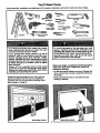
You'll Need Tools
During assembly, installation and adjustment of the opener, instructionswill call for hand tools shown below.
Level
Hack_
_)
A_usta_e End Wrench
An unbalanced garage door might not reverse
when required and someone under the door
could be seriously injured or killed.
If your garage door binds, sticks or is out of
balance, call for professional
garage door
service. Garage doors, door springs, cables,
pulleys, brackets and their hardware are under
extreme tension and can cause serious injury
or death. Do not try to loosen, move or adjust
them yourseffi
Ropes left on a garage door could cause
someone
to become entangled
and killed.
Remove all ropes connected to the door before
Installing and operating the opener.
Identify the type and height of your door and any
special conditions that exist and any additional
materials that may be required by referring to the
lists on page 4 or page 5.
To avoid damage to the garage door and
opener, disable locks before installing and
operating the opener. Use a wood screw or nail
to hold locks in the "open" (unlocked) position.
Operstlon at other than 120V 60 Hz will cause
opener malfunction and damage.
Before you begin, complete the following test to
make sure your door Is balanced, and Is not
stlcldng or binding:
• Lift the door about halfway as shown. Release the
door. it should stay in place, supported entirely by
its springs.
• Raise and lower the door to see if there is any
binding or sticking.
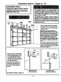
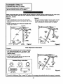
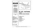
Before you begin, survey your garageareato
see whether any of the conditions belowapply
to your Installation.
Horizontaland vedlsal reinfo(cement
Is needed for I_htweight garagedoors
(fiberglass,steel, aluminum, doorwith g_asspanels,etc.).
See page 24 fordeta_.
RNISHED CEIUNG
Supportbracket&
fasteninghardware
Is required.
See page17.
Slack in ChainTension
ls NomadWben
Garage Doorls CIo_',ed
Header Wall
Safety
Reversing
Sensor-
Closed Position
• Safety ReversingSensor
. Cab_
Pulley
S_Cable
Trolley
Rail Assembly
I
Based on your particular requirements, there are
several installation steps which might call for
materials and/or hardware not included in the carton.
Emergency
Release
Repe & Handle
• Step 1, page 12 - Look at the wall or ceiling above
the garage door. The header bracket must be
securely fastened to structural supports.
• Step 5, page 17 - Do you have a finished ceiling in
your garage? If so, a support bracket and
additional fastening hardware may be required.
Arm
Door Bracket
• Safety reversing sensor, page 21 - Depending
upon garage construction, wood blocks may need
to he fastened to mounting locations before
sensors are installed.
• The opener can be installed within 2 feet of the left
or right of the door center if there is a torsion spring
or center beadng plate in the way of the header
bracket or door bracket area. If your door has
extension springs, the opener must be installed
in the center of the door. See pages 12 and 24.
• Step 10, page 22 - Alternate floor mounting of the
safety reversing sensor will require hardware not
provided.
• Step 11, page 24 - Do you have a steel, aluminum,
fiberglass or glass panel door?. If so, horizontal
and vertical reinforcement is required.
• Do you have an access door in addition to the
garage door?.If not, Model 53702 Emergency
Key Release is required. See page 38.
• Look at the garage door where it meets the floor.
It must close on the floor all the way across.
Other-wise, the safety reverse system may not
work properly. See page 30. Floor or door should
be repaired.
• If your dooris more than 7 feet high, see the longer
rails available on page 38.
You may find It helpful to refer beck to thls page as you proceed with the Installation of your opener.
4
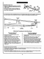
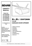
Beforeyou begin,surveyyourgarageareato
seewhetherany of the conditions below apply
FINISHED CEIUNG
S.p_ttnck_
& fastening
hardware Is required.
See page 17.
to your installation.
Slack In chain tension
h;nom_ when
garage doorisclosed.
Header
WJ
Closed Position
Cable
Pulley
BrscketCable
Accesscucx
Header
Bracket
Trolley
T-rail
O
Garage
- Door
3ap betweenfloorand bottomRevendngSensor
of doormustnot e_ceed I/4".
Safety ReversingSensor
Straight Curved
Doo¢
Door
Ann
Arm
One-Piece Door With Track
Based on your particular requirements, there are
several installation steps which might call for
materials and/or hardware not included in the carton.
• Step 1, page 13 - Lock at the wall or ceiling above
the garage door. The header bracket must be
securely fastened to structural supports.
• Step 5, page 17 - Do you have a finished ceiling in
your garage? If so, a support bracket and
additional fastening hardware (not suppl!ed) may
be required.
• Safety reversing sensor, page 21 - Depending on
garage construction, wood blocks may need to be
securely fastened to mounting locations before
sensors are installed.
• Step 10, page 22 - Alternate floor mounting of the
safety reversing sensor will require hardware that
is not provided.
• Step 11, page 25 - Generally, a one-piece door
does not require reinforcement. If your door is
lightweight, you can refer to the information
relating to sectional doors on page 24.
• Step 11, page 25 - Depending on your door's
construction, you might need additional mounting
hardware for the door bracket.
• De you have an access door in addition to the
garage door? If not, Model 53702 Emergency
Key Release is required. See page 38.
• The gap between the bottom of the garage
door and the floor cannot exceed 1/4".
Otherwise, the safety reverse system may not
work propedy. See page 30. The floor or the door
should be repaired.
Bmcket
Door
Straight
Door
Ann
Rope&Handle
You may find it helpfu! to refer back to this page as
you proceed with the Installation of your opener.
5
Opener Carton Inventory
Your garage door opener is packaged in two cartons which contain all parts illustrated below, ff anything is
missing, carefully check the packing material. Parts may be "stuck" in the foam. Hardware for assembly and
installation is shown on page 7.
Models 53824 (2), 53637 (2),
53635 (2), 53629 (1), 53628 {2),
53425 (1), 533_S (1)
Three-FunctionRemote Control
v_thVisorClip (1)
Model 53225 only
0
Models 53637,
53635, & 53425
Model 53635 oNy
%
MulU-Fu_n
_
Entry
Single-FunctionRemoteCo_tr_
v,_thWor Clip (1)
Ughted Console
WallControl
Model 53824 only
Modeb 53225,
53325,53628,53629
_
Cable
PulleyBracket
Header Bracket
Safely Reve_ng Sensor
MountingBracket
W'_ Square Holes (2)
in DispensingCarton
j
Cui_l
Chainand Cable
Door
and
Literature
With Sl<_(2)
HangingBrackets
_
(2) Safety ReversingSensors
(1 SendingEye and I ReceivingEye)
with
2-ConductorWhite & White/BlackBellWire
attached
6
Sva_ht Door
Arm Sec_on
Separate ell hardware from the packages In the rail carton and the opener carton, as
shown below, for the assembly and installation procedures.
Assembly Hardware
WasheredScrew
5/16" - 18 x 1/2" (2)
(mountedIn ogene_
Hex Screw
5/16" - 18 x 7/8" (3)
Nut
5/16" - 18 (5)
Ca_age SCb
1/4" - 20 x 1/2" (4)
©
Trolley"_reeded Shaft(1)
Master[.ink(2)
©
Lock_asher
5/16" (4)
LockNut
1/4" - 20 x 7/16" (4)
Installation Hardware
llllllllllllllltllll[
5/16"- 18 x 7/8" (4)
Rail Grease
lll
lil lllllllll
"*
LagSmmv
5/16"-18x 1-7/8" (4)
NutS/16"-is (6)
(_
LockWasher 5/16" (6)
Ro_
I llllllL I[11111111111111111
Carriage Bolt
Screw
6ABx 1" (2)
5/16"-18 x 2-1/2" (2)
°]
Ck_s P_
5/16" x 2-3/4" (1)
(1o)
_Pin
5/16" x 1" (2)
Futenef (3)
Safety Reversing Sensor
Installation Herd',rare
©
_llllllllll_llll_LIIlll'_
1/4 x 1-1/2" (4)
canoe Scas
1/4"- 20 x 1/2" {4)
LockNut
114"- 20 (4)
Wing Nut (2)
_lllilllllllllllllllllllllllilllllillD
Nut
1/4-20 x 1-1/2" (2)
#10.32 x 5/6" 14)
7
Insulated
Assembly Section: Pages 8 - 11
To avoid Installation difficulties, do not mn the garage door opener until Instructed to do so.
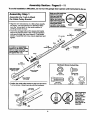
Assembly Step I
Assemble
the T-rail & Attach
the Cable Pulley Bracket
• Align the 3 T-rail sections on a flat surface exactly
as shown. The end sections are identical. Make
sure the "arrow label" on the center section is
pointing toward the door.
Make sure bolt necks are
seated In the square
holes and rails are
aligned beforeyou
tighten lock nuts. (See
right and wrong views).
Improper assembly can
cause Jerkytrolley
operation,noise and/or
nuisance door reversals.
Right
Wrong
TRAIL
BACK
(TOOPENER)
• Insert the carriage bolts so the square bolt necks
seat in the square holes in the T-rail end sections
and pass through the round holes in T-rail center
section. Assemble lock nuts, ensure alignment and
tighten.
T-r_l
1/4" LockNut
(End Sedon)
Brace
If T-roll is not assembled
EXACTLY as shown, trolley
will not travel smoothly
along length of rail or If will
hit against the nuts.
eB_t
1/4"-20_1/2"
Brace
Hardware Shown Actual Size
©
Cable putkDybracket
attach_ to FRONT
END of T-raU
Lod_
Nut
Cardege
Bolts
1/4" - 20 x 7/16"
1/4" * 20 x 1/2"
T-RAILFRONT
(To DOOR)
• Position the cable pulley bracket on the front end of
T-rail as shown. Fasten securely with the hardware.
Ca_e pulley
Bracket
Q
Right
Wrong
sure to keep
bracket parallel
to the rail.
When
Ifghtening
Otherwise,
the
the
screws,
be
rail may bow
when opener Is
operated.
Assembly Step 2
Install
the Trolley
Hardware Shown
Actual Size
I
I
on the T-rail
©©
• Attach the threaded shaft to the trolley with the
lock washer and nuts as shown.
LockWssher
5/16"
Nut
5/16" - 18
Tro_y
LockWasher
5116"
OutorNut
T_
Thm_l
Shaft
kmer Nut
5/16"
Tro,ey
Tempormy
Sto_
Screwdriver
• As a temporary stop, insert e screwdriver into the
hole in the front end of the T-rail.
• Slide the Volley assembly along the rail to the
screwdriver stop.
If trolley hits against any nuts on the Trail, the
bolts and nuts were attached from the wrong
Fide and must be reposltioned. Review Step 1.
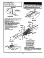
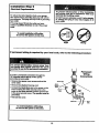
Assembly Step 3
Fasten
the T-rail to the Opener
• Place the opener on packing material to protect
the cover. For convenience, put a s_upportunder
the cable pulley bracket.
• Remove the (2) 5/16"-18xl/2" washered screws
mounted in the top of the opener.
wm
sony
5PI6;18xli2"
• Align the holes in the back section of the T-rail with
the holes in the opener.
Fasten the rail with the (2) washered screws
previously removed. Tighten securely.
T_ 5/16"-18x7/8"
:remember to use only these screwel Any other
screws will cause serious damage to the opener.
(BackSecmon)
_
• Insert a 5/16"-18x7/8" hex screw into the trolley
stop hole in the T-rail as shown. Tighten secqrely
with a 5/16" lock washer and nut. This screw limits
trolley travel in the UP direction.
LockWmJ"mr-5/16"
Nut
5/16"-18
Hardware Shown Actual Size
He_ Screw
5/16" - 18 x 7/8"
Nut
5/16"- 18
LOOK
Wuher
5/16"
9
Assembly Step 4
Install the Chain/Cable &
Attach the Sprocket Cover
entangle¢l In moving opener sprockeL Attach
sprocket cover eecurely. Never operate oPener
I)i_per_ng Carton
Figure
2
op.,_
sprocket
• Detach the cable loop from the carton and fasten it
to the trolley with a master link from the hardware
bag. See master link procedure, Figure 1.
Figure 3
• W'dhthe trolley against the screwdriver, dispense
the cable around the pulley.
• Proceed back around the opener sprocket,
Figure 2. Be sure sprocket teeth engage the
chain. Continue forward to the trolley
threaded shaft, Figure 3.
• Use the second master link to connect
the chain to the fiat end of the shaft.
Check to make sure the chain Is
not twisted.
Master
Link
Ftet End
of Trolley
Master
Chain
• Remove the screwdriver.
,Rn Notch
Figure I
Master Unk Procedure:
Inst_l Clmln andCa_e
In1111sDir_tion
Pushpinsof masterlinkbar
throughcableloopand holein
frontend of trolley.Pushcap
over pinsand intonotches.
Slidedip-on spdngovercap
and intonotchesuntilboth
pinsam securelylocked.
SWod_
Cover
BackTab Slot
To attach the sprocket cover:
• Insert the back tab in the opener slot. Squeeze the
cover slightly and insert the front tab in the slot on
the mounting plate.
10
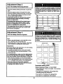
Assembly Step 5
Tighten the Chain & Cable
Outer Nut
Lock
W_hw
Inner Nul
• Spin the inner nut and lock washer down the
threaded shaft, away from the trolley.
• To tighten the chain, tum outer nut in the direction
shown. As yon tum the not, keep the chain
from twisting.
0
• When the chain is approximately 1/2' above the
base of the T-rail at its midpoint, re-tightso the
inner nut to secure the adjustment.
@
Sprocket noise can result if chain is either too
loose or too Ught.
When installation is complete, you may notice some
chain droop with the door dosed. This is normal. If
the chain returns to the position shown when the
door is open, do not re-adjust the chain.
NOTE: During future maintenance, ALWAYS
pull the emergency release handle to disconnect
trolley before adjusting chain.
You have now finished assembling your garage door opener. Please read the following
warnings before I_roceeding to the Installation section:
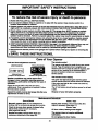
IMPORTANT INSTALLATION INSTRUCTIONS
To reduce the risk of severn injury or death to persons:
1. READ AND FOLLOW ALL INSTALLATION INSTRUCTIONS.
2. install only on a properly balanced and lubricated garage door. An Improperly balanced door
may not reverse and could result In severe Injury or death. Repairs to cables, spring assemblies
and other hardware must be made by a profseslonal-service parson before Installing opener.
3. Disable all locks and remove all ropes connected to the garage door before Installing the opener.
Ropes connected to a garage door can cause entanglement and death.
4. If possible, Install door opener 7 feet or more above flops',with the emergency release handle
mounted 6 feet above the floor.
5. Do not connect the opener to power source until instructed to do so.
6. Locate the Wall Control within sight of the door bt a minimum height of 5 feet where small
children cannot reach and away from all moving parts of the door.
7. Install the User Safety Instruotlon Label on the well adjacent to the control button and the
Malntenanca Instruction Label In s prominent location on the Inside of the garage door.
8. Upon completion of the installation, the door must reverse when It comes in contact wifh a
one-Inch high object or a 2x4 laid flat on the floor.
9. Do not wear watches, rings or loose clothing while Instamng orservlclng an opener. Jewelry or
loose clothing can be caught in the mechanism of the garage door or the opener.
11
Installation Section: Pages 12- 27
Installation Step I
Determine Header Bracket Location
Installation procedures vary according to
garage door types. Follow the instructions
which apply to your door.
a structural support on the header wall or
ceiling, the safety reverse system may not
work properly (see page 30). The door might
not reverse when required, and could cause
serious Injury or death.
The garage door springs, cables, pulleys,
brackets and their hardware are under extreme
tension. Do not attempt to loosen, move or
adjust them yourself. Serious personal Injury
or death could result. Call for professional
garage door scFvlca.
Head_
Wal
2x4
Stmntund
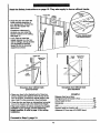
• Close the door and mark the inside
ve "rti_ centerline of the garage door.
• Extend the line onto the header wall
above the door.
Remember, you can fasten the
header bracket within 2 feet of the
left or right of the door center on/yif
a torsion spring or center bendng
plate is In the way; or you can attach
It to the calling (refer to page 14)
when clearance Is minimal. (It may
• be mounted on the wall upside down
if necessary, to gain approxlmetely
1/2%)
If you need to install the header bracket
on a 2x4 (on wall or ceiling), use lag
screws (not supplied) to securely fasten
the 2x4 to structural supports as shown
here and on page 13.
• Open your door to the highest
point of travel as shown. Draw
an intersecting horizontal line
on the header wall 2" above
the high point. This height will
provide travel clearance for the
top edge of the door.
Door clearance brackets are
available for sectional doors
when headroom clearance is
less than 2". See accessory
page 38.
Header
Track
HighestPoint
ofTravel
Highe_PO_
ofTravel
Sectional door
with curved track
Proceed to Step 2, page 14.
12
One-piece door
with horizontal track
Read the Safety instructions on page 12. They also apply to doors without tracks.
HeaderWall
2x4
• Close the door and mark the
inside vertical cantedine of
your garage door. Extend the
line onto the header wall
above door.
If headroom clearance is
minimal, you can install the
header bracket on the ceiling.
See page 14.
O_
CBLING MOUNT
FOR HEADER BRACKET
• ffyou need to install the
header bracket on a 2x4 (on
wall or ceiling), use lag screws
(not supplied) to securely
fasten the 2x4 to structural
supports as shown.
I
Heade¢Well
J
H_hea P0_t
ofTre_4
/i
One-piece door without track
pivot hardware
One-piece door without track
jamb hardware
EXAMPLE
• Open your door to the highest point of travel as
shown. Measure the distance from the top of the
door to the floor. Subtract the actual height of the
door. Add 8" to the remainder. (See Example).
Distance from top of door
(at highest point of travel) to floor ........................... 92'
Actual height of door ............................................. -88"._.
Remainder ..........................................................
.....4"
• Close the door and draw an intersecting horizontal
line on the header wall at the determined height.
If the total number of inches exceeds the height
available in your garage, use the maximum
height possible, or refer to page 14 for ceiling
Installation.
Add .........................................................................
+8"
Bracket height on header wall ...............................
12"
(Measure UP from top of CLOSED door.)
Proceed to Step 2, page 14.
13
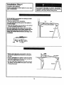
Install
the Header Bracket
Installation
Step 2
You can attach the header bracket either to the
wall above the garage door, or to the calling.
Follow the Instructions which will work best for
your particular requirements.
I
Fasten the Header Bracket to the Wall
• Center the bracket on the vertical guideline with
the bottom edge of the bracket on the horizontal
line as shown (with the arrow pointing toward the
ceiling).
• Mark either set of bracket holes (do not use the
holes designated for ceiling mount). Ddll 3/16" pilot
holes and fasten the bracket securely to a structural
support with the hardware provided.
Wag
MoL_ng Holes
Header
Wag
2)(4
SlrucSJral
Support
-I
Door
Hardware Shown Actual Size
H_h_t
Po_t of Travel
Vertical
Center
Line
(ofGarage
Door)
Fasten the Header Bracket
to the Ceiling
• Extend the vertical guideline onto the ceiling as
shown.
.
.-
• Center the bracket on the vertical mark, no more
than 6" from the wall. Make sure the arrow is
pointing toward the wall. The bracket can be
mounted flush against the ceiling when clearance
is minimal.
I""
""
.'"
Finished
Cllllng-Vertical
Center Line
• Mark holes designated for ceiling mount only. Drill
3/16" pilot holes and fasten bracket securely to a
structural support with the hardware provided.
Door
Spdng
Ceiling Mounting Holes
I
/,,,
5/16"x18xl-7/8"
Header_
Wall
The nail hole is for positioning only.
You must use lag screws to mount
the header bracket.
14
Attach
the T-railStep
to the 3Header Bracket
Installation
I
• Position the 6pener on the garage floor below the
header bracket. Use packing material as a
protect'we base.
//
/'-,///
/ /
//
--
HeaderWall
If the door spring is In the way you'll need help.
Have someone hold the opener securely on a
temporary support to allow the T-rail to clear the
spring.
Header
Bracket
//
/ /
.//
/
/
Cable
• Position the cable pulley bracket against the header
bracket.
Bracket
//
/
/
/
/
• Align the bracket holes and join with a clevis pin as
shown.
• Insert a ring fastene'rto secure.
Clev_Pin
5/16")Q-3/4
•
Door
Hardware Shown Actual Size
°1
(_vle Nn
5/16" X 2-3/4"
15
Cable
Pt_y"
Bracket
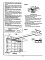
Installation Step 4
Position the Opener
Follow instructions
type as Inustbrated.
which apply to your door
A 2x4 laid flat is convenient for setting an ideal
door-to-T-rail distance.
• Raise the opener onto a stepladder.
T-rail
You will need help at this point ff the ladder Is
not tall enough.
• Open the door all the way and place a 2x4 laid fiat
on the top sec/Jon beneath the T-rail.
If the top panel hits the trolley when you raise
the door, pull down on the trolley release arm to
disconnect the inner and outer sections. The
trolley can remain disconnected until Step 12 is
comple_d.
• W'dh the door ful_ open and parallel to the floor,
measure the distance from the floor to the top of
the door.
• Using a stepladder as a support, raise the opener
to the same distance as the door from the floor (it
will be at a slight angle as shown).
• The top of the door should be level with the top of
the opener. Do not position the opener more than
2" above this point.
16
2x4
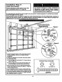
Installation Step 5
Hang
the Opener
Two representatlve Installations are shown.
Yours may be dlfferent. Hanging brackets should
be angled, Figure 1, to provide rigid support. On
finished ceilings, Figure 2, attach a sturdy metal
bracket to structural supports before installing the
opener. The bracket and fastening hardware are not
suppfied. See accessory page 38.
Figure I
Structund
• Measure the distance from each side of the opener
to the structural support.
• Cut both pieces of the hanging bracket to,:required
lengths.
S_ev_
5/16_(1-7/8=
• Ddll 3/16" pilot holes in the structural supports.
• Attach one end of each bracket to a support with
5/16"xl-7/8" lag screws.
• Fasten the opener to the hanging brackets with
5/16"-18x7/8" screws, lock washers and nuts.
• Check to make sure the T-rail is centered over the
door (or in line with the header bracket if the
bracket is not centered above the door).
• Remove the 2x4. Operate the door manually. If the
door hits the rail, raise the header bracket.
5/16"-181a/8"SGrew
5/16" LodeWMher
5/16"-18 Nut
Figure 2
Grease the top and underside of the_,,_
rail surface where the trolley __,_
slides. A tube of grease Is ___
I
I
I
supplied.
I
_
Hardware Shown Actual Size
5/16"-18 x 1-7/8"
5/16"-18x7/8
°
Nut 5/16"-
18
LockWasher
5/16"
17
I
Installation Step 6
Install the Wall Control
Children operating or playing with a garage
door opener can Injure themselves or others.
The garage door could close end cause serious
Injury or death.
Install the Wall Control (or any additional push
buttons) out of the reach of children and away
from all moving parts of the door and door
hardware, but where the garage door is visible.
Do not allow children to operate the push
button(a) or the remote control(s).
• Strip 1/4" of insulation from one end of the bell
wire; connect the wire to the two screw terminals
on the back of the Wall Control: white to 2 and
white/red to 1.
• Locate the Wall Control within sight of the door
at a minimum height of 5 feet where small
children cannot reach, and away from all
moving parts of the door and door hardware.
Fasten the Ughted Push Button Wall Control
securely with 6ABx1-1/2" screws. The console
style uses 6ABxl" screws. If installing into drywall,
ddll 5/32" holes and use the anchors provided.
A moving garage door could Injure someone
under It. Activate the opener only when the
door is properly adjusted, you can see it clearly,
and there are r_oobstructions to door travel.
• Run the bell wire up the walt and across the ceiling
to the opener. Use insulated staples to secure the
wire in several places. Be careful not to pierce the
wire with a staple, thereby resulting in a short.
• Receiver terminal screws and the antenna are
located on the back panel of the opener. Position
the antenna wire as shown.
Do NOT.connect
the power and operate the
opener at this time. The trolley will travel to the
full open position but will not return to the
close position
until the sensor beam Is
connected end properly aligned.
See Safety Reversing
beginning on page 21.
• Then connect the hell wire to the opener terminal
screws: white to 2; white/red to 1.
• Remember to affix the User Safety Instruction
label to the wall near the Wall Control, and the
Maintenance Instruction label in a prominent
iocstlon on the Inside of the garage door.
If the label adhesive will not adhere to your garage
wall surface (or becomes loose with time) use tacks
to secure the label alongside the wall control.
Page 32 explains how to operate the opener using
the lighted push bar or button, as well as the Lock
and Ught features on the Deluxe Wall Control.
Sensor
Instructions
Outdoor Key Switch Accessory Connections
To Opener terminal screws: white to 2; white/red to 1
Lighted Push Button
Wall Control
Deluxe Wall Control
Lighted Console Wall Control
Terminal
Screws TopInstallation
Range
Hardware Shown Actual Size
_ lllll,ltlillltl#lllllllllllll_l_>
6AS x 1-1/2" Sorew
Ughmd
PInkBuaen
Wa=C,:m_
insulated
_
Bottomln41tallation
6ABx 1" Sinew
Lighted
Console
WaSCam_
Range
Dry Walt Anchors
BackPanel
of Opener
18
I
Installation Step 7
Install the Light and the Lens
Install the Ilghta
• Install a 75 watt maximum light bulb in the socket.
The light Jill turn ON and remain lit for
approximately 4-1/2 minutes when power is
connected. Then the light will turn OFF.
LensGuide
• If the bulb bums out prematurely due to vibration,
replace it with a standard neck "Garage Door
Opener" bulb.
Ught
Install the lens (except for Model 53225)
• Apply slight pressure on the sides of the lens and
slide the tabs into the slots in the end panel.
• Reverse the procedure to remove the lens.
Installation Step 8
Attach
Rope
the Emergency
Release
Do not use the red handle to pull the door
open or closed. The rope knot could become
untied and you could fall. Usa the emergency
release only to disengage the trolley end, If
possible, only when the door Is closed.
and Handle
Garage doors are heavy. If the door Is open
when the handle Is pulled, the door could
close inadvertently
If It is not properly
balanced. Sedous Injury may result to persons
under the door. Make sure the doorway is clear
of persons end obstructions
before pulling
handle when door is open.
Overhand
Knot
• Thread one end of the rope through the hole in the
top of the red handle so "NOTICE" reads fight side
up as shown. Secure with an overhand knot.
The imot should be st least 1 • from the end of the
rope to prevent slipping.
Rope
Emergency
• Thread the other end of the rope through the hole in
the release ann of the outer trolley.
Overhand
Knot
• Adjust rope length so the handle is 6 feet above the
floor. Secure with an overhand knot.
ff it Is necessary to cut the rope, heat seal the cut
end with • match or lighter to prevent unraveling.
19
Installation Step 9
Electrical
i
Requirements
[
I
To prevent electrocution or fire, Installation
end wiring must be In compliance with local
electrical and building codes.
To reduce the risk of electric shock, your garage
door opener has a grounding type plug with a third
grounding pin. This plug will onlyfit into a grounding
type outleL
Do NOT use an extension cord, 2-wire adapter,
or change the_plug in any way to :Make it fit
your outleL
If the plug doesn't fit into the outlet you have,
contact a qualified electrician to instP!lthe proper
outlet,
do
nm Installation
the opener difficulties,
at thls time.
Tonot
avoid
Right
Wrong
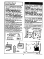
If permanent wiring is required by your local code, refer to the following procedure:
Permanent
Wiring
Connections
To make a permanent connection through the
7/8' diameter hole in the top of the opener
(according to local code):
• Remove the opener cover screws and set the
cover aside.
Gmen
Ground
• Remove the atlached 3-prong cord.
• Connect the black (line) wire to the screw on the
brass terminal; the white (neutral) wire to the
screw on the salverterminal; and the ground wire
to the green ground screw. The opener must be
grounded.
• Reinstall the cover.
WIro
wh;te Wire
I
doTonot
avoid
nm Installation
the openor difficulties,
at this time.
I
20
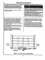
Safety Reversing System
Information you'll need before you begin the Inatallation of the safety reversing sensor.
The safety reversing sensor mustbe connected
and aligned correctly before the garage door
opener will move In the down direction. This Is a
required safety device and cannot be disabled.
Without a properly working safety reversing
sensor, persons (particularly children) could
be Injured or killed by a closing garage door.
Read and follow all Instructions.
InstallaUon procedures are the same for s_tional
and one-piece doors.
To protect small children, Install the safety
reversing sensor so that the beam will be no
higher than 4"-6" above the garage floor.
Disconnect power to the garage door opener
before Installing the safety reversing sensor.
I
Be sure power to the opener Is disconnected.
The sending eye transmits an invisible light beam to
the receiving eye. The units can be inst;dled on
either side of the garage door as long as the sun
never shinas dirsctiy into the receiving eye lens.
Look at the label on the connector end of each case
to identify the sensors.
The brackets must be connected and fastened so
that the sending and receiving eyes face each other
as shown in Ftgura 1.
The brackets'must be securely fastened to a solid
surface such as the studs on either side of the door,
or add a piece of wood at each location if installing in
masonry construction.
The invisible light beam path must be unobstructed.
No part of the garage door (or door tracks, spdngs,
hinges, rollers or other hardware) can interrupt the
beam while the door is closing. If it does, use a piece
of wood to build out each sensor mounting location to
.the minimum depth required for light beam clearance.
If an obstruction breaks the light beam while the
garage door is closing, the door will stop and
reverse to full open position and the opener lights
will flash for 5 seconds.
Sensor Beam
4-6" ms0(.
abovef,o_
\
Figure 1: Facingthe doorfrom Insidethe garage
21
Installation Step 10
Install
the Safety
Reversing
I
I
Sensor
Figure 2"
Figures 2 and 3 show assembly of brackets and
'C" wrap based on the recommended installation of
the sensors as shown on page 21.
Mour_ngBracket
WithSquareHokm
However, Figures 4 and 5 are variations which may
fit your installation requirements better. Make sure
the wraps and brackets are aligned so the
sensors will face each other across the garage
door.
#10 - 32
LockNUts
• Fasten the "C" wraps to the mounting brackets
having square holes, using the hardware shown
in Figure 2.
• Connect each assembly to a slotted bracket, using
the hardware shown in Figure 3.
Figure 3
Note the alignment of the brackets for left and
right aldea of the door.
1/4 x 1-1/2"
LagScrews
• Finger tighten the lock nuts.
• Use bracket mounting holes as a template to
locate and drill (2) 3/16" diameter pilot holes on
both sides of the garage door, 4'-6" above the
floor but not exceeding 6: (See waming on
page 21 .)
• Attach bracket assemblies with 1/4"xl -1/2" lag
screws as shown in Figure 3.
"C' Wrap
• Adjust right and left side bracket assemblies to the
same distance out from the mounting surface.
Make sure all door hardware obstructions am
cleared. Tighten the nuts securely.
Mounting
Bracket
t(ithSquareHoles
Hardware Shown Actual Size
©
©
#10.32 x3/8"
Screw
#10x32
LockNut
1/4"- 20 x 1/2"
L.0scr_
1/4" - 20
slap_
Figure 4
LockNut
Figure 5
Alternate Wall Mount
Altemate Root Mount
Sensorwithwire
IrKrK=ator
Ught
MountingBracket
with Slot
Bracket
Attachwith
concruteanchom
(not pr_/Ided)
22
• Ce_ereachsensorunitin a "C' wrap
with lenses
pointing toward each other across the door (see
Figure 6).
Figure 6
• Secure sensors with the hmdware shown. Finger
tighten the wing nut on the receiving eye to al ow
for final adjustment. Securely tighten the sending
eye wing nut.
• Run the wires from both sensors to the opener.
Use insulated staples to secure wire to wall and
ceiling.
• Strip 1/4" of insulation from each set of wires.
Separate white and white/black wires sufficiently to
connect to the opener terminal screws: white to 2
and white/black to 3.
114-20x 1-1/2"
Hex Ben
Trouble Shooting
1. If the sending eye indicator light does not glow
steadily after installation, check for:.
• Plug in the opener. Make sure the Lock Feature is
off. Green indicator lights in both the sending and
receiving eyes will glow steadily if wiring
connections and alignment are correct.
• Electric power to the opener.
• A short inthe white or white/black wires. These
can occur under staples or at screw terminal
connections.
If the indicator light is oflin the receiving eye (and
the invisible light beam path is not obstructed),
alignment is required.
• Incorrect widng between sensors and opener.
• Loosen the receiving eye wing nut to allow slight
rotation of unit. Adjust sensor verticelly and/or
horizontally until the green indicator light glows
with a steady light,
• An open wire (wire break).
2. If the sending eye indicator light glows steadily but
the receiving eye indicator light doesn't:
• Check alignment.
• When indicator lights are glowing steadilyin both
units, tighten the wing nut in the receiving eye unit.
• Check for an open wire to the receiving eye.
Hardware Shown Actual Size
Figure 7
1/_.20 x 1-1/2"
Connect_re to
OpenerTerminals
Bell Wbe
WAIl Control
Sensor
OPENER TERMINAL SCREWS
23
Installation Step 11
Fasten Door Bracket
Follow instructions which apply to your door
type as illustrated below or on page 25.
A horizontal brace should be long enough to be secured to 2 vertical supports. A vertical brace should
cover the height of the top panel.
The IllustrstJon shows one piece of angle iron as the horizontal brace. For the vertk!al brace, 2 pieces of
angle iron are used to create a "U"-shaped support. The best solution Is to check with your garage door
manufacturer for an opener installation door reinforcement klL
Header
Figure I
Figure 2
• Center the door bracket on the previously marked
vertical guideline used for the header bracket
installation.
• Position the bracket on the face of the door within
the following limits:
A) The top edge of the bracket 2"-4" below the top
edge of the door.
Hardware Shown Actual Size
©
B) The top edge of the bracket directly below any
structural suppod across the top of the door,
• Mark and ddll 5/16" left and dght fastening holes.
Secure the bracket as shown in Figure I if there is
vertical reinforcement.
Nut 5/16"-18
If your installation doesn_ require vertical reinforcement but does need top and bottom fastening holes
for the door bracket, position the door plate over the
door bracket as shown in Figure 2. Fasten securely
with hardware shown in Figure 1.
LockWasher 5/16"
5/16"-18 x 2-1/2"
24
Please read and comply with the wamings and reinforcement InstrucUons on page 24.
They apply to one-piece doors also.
Header Wall
Header
Brac_t
Bracket
Placement
of Door
Bracket
Vertical
Garage Door
Door
Bracket,
ofDoor
5/16"-18x2-1/2
• Center the bracket on the top of the door, in line
with the header bracket as shown. Mark holes.
Hardware Shown Actual Size
• Ddll 5/16" pilot holes and fasten the door bracket
with hardware supplied.
@ ©
If the door has no exposed framing, drill 3/16' pilot
holes and fasten the bracket with 5/16"x1-1/2" lag
screws (not supplied) to the top of the door.
NU_ 5/16"-18
The door bracket may be Installed on the top
edge of the door if required for your Installation.
(Refer to the dotted line optional placement
drawing.) Drill 3/16" pilot holes and substitute
5/16"xl-1/2" lag screws (not supplied) to fasten
the bracket to the door.
LockWasher
5/16,-18 x 2-1/2"
25
5/16"
Installation Step 12
Connect
Door Arm to Trolley
Follow instructions which apply to your door
type as Illustrated below and on page 27.
Make sure garage door is fully closed. Pull the emergency release handle to disconnect the outer trolley
from the Inner trolley. Slide the outer trolley back (away from the door) about 2" as shown in
Figures 1, 2 and 3.
Figure 1:
Figure 2:
Fasten straight door arm section to outer trolley
with a clevis pin. Secure the connection with a ring
fastener.
• Bring orm sections together. Find two pairs of holes
that line up and join sections. Select holes as far
apart as possible to increase door arm rigidity.
Fasten curved door arm to the door bracket in the
same way as shown.
Inner Trolley
R_ease
Handle
Door Arm
"_
Curved
oo_m
5/16"-18x7/8"
DoorBraCket
Figure I
Figure 2
Hole Alignment Alternative
Rgure 3:
• If holes in curved arm are above holes in straight
arm, disconnect straight arm. Cut about 6" from
the solid end. Reconnect to trolley with cut end
down as shown.
• Bdng arm sections together.
• Find two pairs of holes that line up and join with
screws, lock washers and nuts.
Hardware Shown Actual Size
@ ©o
Nut 5/16"-18
LockWasher
5/16"
•
Ring Fastener
@111111111111[
°n
He_ Screw
5/16,- 18 x 7/6,
Screws
5/I 6"-18x7/8"
Figure 3
Clevis Pin
5/16" x 1"
Proceed to Adjustment Step 1, page 28. Trolley will re-engage automatically when the opener is operated.
26
Assemblethe DoorArm:
Door
Bracket
• Fasten the straight and curved door arm sections
together to the longest possible length (with a 2 or
3 hole overlap).
ClevtsP_
• With the door closed, connect the straight door
arm section to the door bracket with a clevis pin.
Str_dght
Ann
• Secure with a ring fastener.
5/16"-18x9'/8 _-_
Cun/ed
Do_xAnn
On one-piece doors, before connecting the door arm to bhetrolley the travel limitsmust be adjusted. Umit adjustment
screws are located on the left side panel as shown on page 28. Follow adjustment procedures below.
FuiyC_)sed
Trolley
..... .'__-"
!
|
t
|
C_sed
Door
Open Door
Doorwith
BackwardSlant
I
Adjustment
DoorAnn
Procedures for One-Piece
Open Door Adjustment:
Decrease UP limit
Doors
Closed Door Adjustment:
Decrease DOWN limit
• Turn the UP limit adjustment screw counterclockwise 5-1/2 turns.
•Tum the DOWN limit adjustment screw clockwise 5
complete turns.
• Press the Wall control push bar or button. The
trolley will travel to the fully closed position.
• Press the Wall Control push bar or button. The
trolley will travel to the fully open position.
• Manually raise the door to the open position
(parallel to the floor), and lift the door arm to the
trolley. The arm should touch the trolley just in
back of the door arm connector hole. Refer to the
fully open trolley/door arm positions in the
illustration. If the arm does not extend far enough,
adjust the limit further. One full turn equals 2" of
trolley travel.
• Manually close the door and lift the door arm to the
trolJey.The arm should touch the trolley just ahead
of the door arm connector hole. Refer to the fully
closed trolley/door arm positions in the illustration. If
the arm is behind the connector hole, adjust the limit
further. One full tum equals 2" of trolley travel.
Connect the door arm to the trolley.
• Close the door and join the curved arm to the connector hole in the trolley with the remaining clevis pin. It may
be necessary to lift the door slightly to make the connection.
• Secure with a ring fastener.
• Run the opener through a complete travel cycle. It the door has a slight "backward" slant in full open position
as shown in the illustration;'decrease the UP limit until the door is parallel to the floor.
27
Adjustment Section: Pages 28 - 30
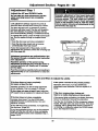
Adjustment Step 1
Adjust the UP and DOWN Limits
Do not make any limit adjustments unUI the
safety reversing sensors are completely
Installed.
Umit adjustment settings regulate the points at
which the door will stopwhen moving up or down.
The door will stop in the up direction if anything
interferes with door travel. The door will reverse in
the down direction if anything interferes with the
door travel (including binding or unbalanced doom).
To operate the opener, press the Wall Control push
bar. Run the opener through a complete travel
cycle.
Urr_
_lu_mer4
Screws
• Does the door open and close completely?
• Does the door stay closed end not reverse
unintentionally when fully closed?
...............
-/o
o _'_=
If your door passes both of these tests, no limit
adjustments are necessary unless the reversing test
falls (See page 30).
LeftSidePan_
Adjustment procedures are outlined below. Run
the opener through a complete travel cycle after
each adjustment.
Repeated operation of the opener during
adjustment procedures may cause the motor to
overheat and shut off. Simply walt 15 minutes
and try again.
Read the procedures carefully before proceeding to
Adjustment Step 2. Use a screwdriver to make limit
adjustments.
How and When to Adjust the Limits
If the door does not open completely
but opens at/eaat five feet
Increase up travel. Turn the UP limit adjustment
screw clockwise. One tum equals 2" of travel.
If the opener reverses In fully closed pesitlon
Decrease down travel. Turn the DOWN limit
adjustment screw clockwise. One tum equals 2" of
travel.
If door does not open at least 5 feet: Adjust the
UP (open) force as explained in Adjustment Step 2.
ff thq door reverses when closing and
there is no visible Interference to travel cycle
If the door does not close completely
increase down travel. Tum the DOWN limit
adjustment screw counterclockwise. One turn
equals 2" of travel.
If the opener lights are flashing, the Safety Reversing
Sensor is obstructed. Remove the obstruction.
Test the door for binding: Pull the emergency release
handle. Manually open and close the door. If the door
is binding, call for garage door service. If the door is
not binding or unbalanced, adjust the DOWN (close)
force. See Adjustment Step 2.
If door still won1 close completely, try lengthening
the door arm. (Page 26.)
If you have adjusted the door arm to the maximum
length and the door still will not close completely,
lower the header bracket. See Installation Step 1,
pages 12/13.
28
I
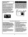
Adjustment Step 2
Adjust
the Force
I the prop_on
Force adjustment controls are located on the beck
panel of the opener. Force adjustment set'rings
regulate the amount of power required to open end
close the door.
I
The door will stop in the up direction if anything
interferes with its travel. The door will reverse in the
down direction if anything interferes with its travel
(including binding or unbalanced doors).
of the safety
reverse
d.oormlg !notreverse
propa y
when required and could seriously Injure or Idll
someone under It. Do not Inoreaos the force
beyond the minimum amount required to close
the doer. Do not use the force adjustments to
compensate for • binding or sticking garage
door. Test the safety reverse system following
all adjustments to force levels. See page 30.
If the forces are set too light, door travel may be
interrupted by nuisance reversals in the down
direction end stops in the up direction. Weather
conditions can affect the door movement, so
occasional adjustment may be needed.
The maJdmumforce adjustment range is 260 degrees,
about 3/4 of a complete rum. Do not force controls
beyond that point. Tum force adjustment controls
with a screwdriver.
AdjulwnentLlbe
How and When to Adjust the Forces
Test the DOWN (close) force
Make 10 degree tum adjustments until the door stops
easily. After each adjustment, run the opener through
a complete travel cycle.
Grasp the door bottom when the door is about
halfway through DOWN (close) travel. The door
should reverse. Reversal halfway through down
travel does not guarantee reversal on a two.inch
obstruction. See page 30. If the door is hard to
hold or doesnt reveme, decrease the DOWN (close)
force by turning the control counterclockwise.
If the doer doesn't open at least 5 feet _J
Increase UP (Open) force by turning the control
clockwise. Make 10 degree turn adjustments u_til
door opens completely. Re-adjust the UP limit if
necessary. After each adjustment, run the opener
through a complete travel cycle.
Make 10 degree rum adjustments until the door
reverses normally. After each adjustment, run the
opener through a complete cycle.
If the doer reverses during the down (close) cycle
and the opener lights aren=t flashing
Test the UP (open) force
Increase DOWN (close) force by tuming the control
clockwise. Make 10 degree turn adjustments until the
door completes a close cycle. After each adjustment,
run the opener through a complete travel cycle. Do
not Increase the force beyond the minimum
amount required to close the doer.
Grasp the door bottom when the door is about
halfway through UP (open) travel. The door should
stop. if the door is hard to hold or doesn't stop,
decrease UP (open) force by turning the control
counterclockwise.
29
Adjustment
Step 3
Test
Reversing
The Safety
Sensor
• Press the remote control push button to open the
door.
• Place the opener carton in the path of the door.
I
• Press the remote control push button to close the
door. The door will not move more than an inch,
and the opener light will flash.
I--7oF--]
Professional service Is required If the opener
closes the door when the safety reversing
sensor Is obstructed.
The garage door opener will not close from a
remote control If the Indicator light In either
sensor Is off(alerting you to the fact that the
sensor Is mlssligned or obstructed).
The garage door can be closed by pressing and
holding the Wall Control push bar or button until
down travel is completed.
Adjustment
Test the Safety
Safety Rev_
Sensor
_
Safety Reversing
Step 4
Reverse
System
persons trapped by a closing garage door.
Repeat this test once a month and adjust as
Test:
• Place a one-inch board (or a 2x4 laid flat) on the
floor, centered under the garage door.
• Operate the door in the down direction. The door
must reverse on striking the obstruction.
l
Adjustment:
If the door stops on the obstruction, it is not traveling
far enough in the down direction.
• Increase the DOWN limit by tuming the DOWN
limit adjustment screw counterclockwise 1/4 tum.
• Repeat the test.
On s sectional door, make sure limit adjustments
do not force the door arm beyond a straight up
and down position. See the Illustration on page 26.
• When the door reverses on the one-inch board,
remove the obstruction and run the opener through
3 or 4 complete travel cycles to test adjustment.
If the door will not reverse after repeated
adjustment attempts, call Sears Service Center
for garage door opener service.
_4
Important
lald flat)
safety
check
Repeat Adjustment Steps 1, 2 and 4 after:
• Each adjustment of door arm length, force controls
or limit controls.
• Any repair to or adjustment of the garage door
(including springs and hardware).
• Any repair to or buckling of the garage floor.
• Any repair to or adjustment of the opener.
30
IMPORTANT SAFETY INSTRUCTIONS
To reduce the risk of severe injury or death to persons:
1. READ AND FOLLOW ALL INSTRUCTIONS.
2. Do not permit children either to operate or to play with the opener. Keep remote control In s
location Inaccessible to children.
3. Operate opener only when the door Is In full view end froe from any obstruction. Keep the door In
sight until it Is completely closed. NO ONE SHOULD CROSS THE PATH OF THE MOVING DOOR.
4. Check safety reversal system monthly. See page 30. The garage door MUST reverse on contact
with • one-Inch (or • 2x4 board laid flat) object placed on the floor. If an adjustment Is made to
either the force or the limit of travel, both adjustments may be needed and the safety reversal
system must be checked. Failure to properly adjust the opener may result In severe injury or death.
5. If possible, use the emergency release only when the door Is In a closed position. Caution should
be taken whenever the disconnect cord Is actuated'with the door open. Weak or broken springs
may cause the dour to fall rapidly, causing Injury or death to persons.
6. KEEP GARAGE DOORS PROPERLY BALANCED. See page 3, An Improperly balanced door may not
revenm when required and could result In severe Injury or death. Repairs to cables, spring
eesambllee and other hardware must be made by • professional garage door person.
7. Disconnect the electric power to the garage dour opener before making any repairs or removing the
covers.
8.SAVE THESE INSTRUCTIONS.
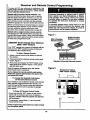
Care of Your Opener
The remote control
Limit end force adjustment controls
Limit Controls
I
The opener must learn the code of any new remote
control. Page 33 explains how to program your
receiver and how to erase all codes if required. Self
service of your receiver is not recommended. If
service is needed, contact your nearest Sears
Service Center.
Force Controls
-'Z°) I
AdJU
A_U
0.ocated
on,_ele_Ode_na_)
Label
(Lmmdon_e _t _
pw_)
The remote control batteP/
Weather conditions may cause some minor
changes In dour operstlon requidng some readjustments, perticulerly during the first year of
operation.
The green test light should glow and the opener
should operate when the remote control is activated.
ff the green test light is dim ordoes not come on,
replace the hattery.
Pages 28 and 29 refer to the limit and force
adjustments. Only a screwdriver is required. Follow
the instrucltons carefully.
The _2 Volt battery should produce power for at least
a year.
Repeat the safety reverse test (page 30) after any
adjustment of limits or force.
Dlspoee of your old battery properly.
Maintenancd Schedule
Once a Month
Twice a Year
Manually operate door. If If is unbalanced or
binding, call for professional garage door service.
Check chain tension. Disconnect trolley first.
Adjust If necessary (See page 11).
Once a Year
Check to be sure door opens & closes fully.
Adjust limits alxI/or force if necessary.
(See pages 28 and 29.)
OII door rollers, beednge end hinges
The openerdoee
lubrication.
Repeat the safety reverse teeL Make any
necessary adjustments (See page 30).
not require additional
DO not grease the door tracks.
31
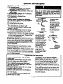
Operation of Your Opener
Aotlva_ the opener v_lh any of the fullowing:
1. The Remote Control
• 3-FuncUon and C_mpact: Hold large push
button down until the door starts to move.
Weak or broken springs could allow an open
door to fall (either rapidly or unexpectedly),
resulting in serious Injury, death or property
damage. If possible,
use the emergency
release rope end handle on/y when the door Is
fully closed.
• Single function: Hold push button until the door
starts to move.
2. The Wall Control. Hold push bar or button down
until the door starts to move.
3. The Key Switch or Keylees Entry.
(See Acneesodes)
When the opener is activated with the safety
reversing sensor Installed end correctly aligned:
O'
@
To open the door
manually:
The door should be
fully closed If possible.
Pull down on the red
emergency release
handle and liftthe door
manually. To
reconnect the door to
the opener, press the
Wall Control push bar
or button.
Tmley
RW
Arm
1. fl opan, the door will close. If cloesd, it will open.
2. If closing, the door will reverse.
3. If opening, the door will stop (allowing space for
entry and exit of pets and for flesh air).
4. If the door has been stopped in a partially open
position, it will dose.
P,ekwse
Hand_
(Pu,Down)
Manual disconnect
position
5. If obstructed while closing, the door will reverse.
• 6. If obstmctod white opening, the door will stop.
7. The garage door wil reverse in the dosing cycle when
the _
beam is broken. If tully open, the door will
not dose when _ beam is broken. The sensor has
no eftect in the opaning cycis.
The lockout feature
prevents the trolley
from reconnecting
automatically. Pull the
emergency handle
down and back (toward
the opener). The door
can then be raised and
lowered manually as
often as necessary. To
disengage the lockout
feature, pull the
emergency handle
straight down. The
trolley will reconnect on
the next UP or DOWN
operation.
If the sensor is not installed or not aligned correctly,
the door won't close from any remote control. You can
close the door with the Wall Control, the Key Switch,
or Keyleas Entry, however, if you activate them until
down travelis complete. If you release them too soon,
the door w_t reverse.
The opener lights will blink for 5 seconds when the
safety reversing sensor causes the door to reverse.
The Opener Lights will tum on under the following
conditions:When the opener is initiallyplugged in; when
the power is intent_ed; when the opener is activated. It
will turn off automatically after 4-1/2 minutes or provide
constant light when the Light feature is activated. Bulb
size is 75 watts maximum.
@
F_ease Arm
Emergency
Release Handle
(Pull Down& Back
To*ards Ope_r)
Lockout position
Operation of the Wall Control
Press the lighted push bar or button to open or
close the door.
Lock fsatum: The Lock feature is designed to
prevent operation of the door from portable remote
cotltmls. However, the door will open and close
from the Deluxe Wall Control push bar, the Key
Switch and the Multi-Function Keyisse Entry.
To activate: Press and hold the Lock button for
2 seconds. The push bar light will flash as long as
the Lock feature is on.
Press again to reverse the door during the dosing
cycle or to stop the door while it's opening.
Deluxe Lighted Console (model 53824 only)
Light feature: Press the Light button. If the opener
5ght is off, ;t will tum on.
If the opener light is on, (even in the 4-1/2 minute
automa_ cycle) it will tum off.
To turn off: Press and hold the Lock button again
for 2 seconds.The push bar light will stop flashing.
Normal operation will resume. The Lock feature will
also turn oft whenever the SRT button on the opener
end p_al is activated.
BUt if you use the Light button to turn the light on
and then activate the opener, the light will turn off
after 4-1/2 minutes.
The Light button will not control the opener light
when the door is tn too'don.
32
Receiver and Remote Control Programming
To comply with FCC rules, adjustment or modificationsof this
receiver and/or transmitter are prohibited,except for changing
the code setting or replacing the battery, THERE ARE NO
o'n.IER USER SERVICEABLE PARTS.
Models with 3-function remote controls: The
remote control(s) has been factory set to operate
with the large push button. However, you can use
either of the two small buttons, if you prefer. And,
the 3-function remote control(s) can also activate
additional garage door openers and/or light controls.
Children operating or playing with s garage
door opener can Injure themselves or others.
The garage door could close and cause
serious Injury or death. Do not allow children
to operate the wall push button(s) or remote
control(s).
Below are instructions for programming your opener
to match the other buttons on your remote controls
and any additional remote controls you may
purchase. See available accessories on page 38.
A moving
garage door could Injure or kill
someone under It. Activate the opener only
when you can see the door clearly, It is free of
obstruCtions, and Is properly adjusted.
Models with a single-function remote control:
The garage door will operate when you press the
remote control push button. Refer to the information
below if you want to add a 3-function remote control
or erase your programmed code.
Figure I
Mini 3-Function
Remote Control
Single FunCtion
Remote Control
53000SRT Series Garage Door Openers
(With "SRT" Button)
Your "SR'I" garage door opener will operate with as
many as four "SRT" portable remote controls and
one Multi-Function Keyless Entry.
To-Add A Remote Control
1. Select a remote control push button to operate
the receiver.
2. Press and holdthe selected remote control push
button, Figure 1.
Standard 3-Function
Remote Control
3. Then press and release the "SR'I" button on the
back panel of the opener, Figure 2. The opener
light will flash once.
Figure 2
Now the opener will operate when the remote
conVol push button is pressed.
Garage Door Opener
(With "Smart" Button)
If you release the remote control push button
before the opener UgM flashes, the opener will
not accept the code.
7
V
To Change the Selected Push Button
"
On the Same Remote Control
If you decide to use a different remote control button
than originally programmed into the opener, you
need to erase aJlthe leamed codes and reprogram
each remote control used to operate the garage
door opener.
To Erase All Remote Control
Codes
"SRT" Indicator
Buttoe Light
• Press and hold the "SRT" button on the opener
panel until the indicator light turns off (about 6
seconds). AIIthe codes the opener has learned
will be erased.
END PANEL
• To rsprogram, repeat Steps 1, 2 and 3 for each
remote control in use.
Code programming Instructions
on the opener panel.
are also located
33
Having a Problem?
Situation
Probable Cause and Solution
The opener doesnl
operate from either
the Wall Control or
the remote control:
1. Does the opener have electd.cpower? Plug.a lamp into the outlei, ff it doesn't light,
check the fuse box or the drcuit breaker. (Some outlets are controlled by a wall switch.)
2. Have you disabled all door locks? Review installationinstructionwarnings on Page 11.
3. Is there a build-up of ice or snow under the door? The door may be frozen to the
ground. Remove any restdction.
4. The garage door spdng may be broken. Have it replaced.
5. Repeated operation may have tripped the ovedoed protector in the motor. Wait
15 minutes. Try again.
Opener operates
from the remote
control, but not from
the Wall Control:
1. Is the Wall Control lit? If not, remove the bell wire from the opener terminal screws.
Short the red and white terminals by touching both terminals at the same time with a
piece of wire. If the opener runs, check for a faulty wire connection at the Wall
Control, a short under the staples, or a broken wire.
2. Are the widng connections correct? Review Step 6, page 18.
The door operates
from the Wall Control,
but not from the
remote control:
1. If your model has the Look feature, make sure the lock is Off.
2. Is any wall push button flashing? Your opener needs to re*learn a remote control
code. Refer to Instructions on the opener panel.
3. Does the battery test light glow when the remote control push button is pressed? If
not, replace the battery.
4. Program the receiver to match the remote control code.
5. Repeat the receiver programming procedure with all remote controls.
The remote control
has short range:
1. Check the battery test light. If the light is dim, replace the battery.
2. Change the location of the remote control in.your car.
3. Check to be sure the antenna on the side or back panel of opener extends fully
downward.
4.
Some installations may have shorter range due to a metal door. foil backed
insulation, or metal garage siding.
Opener noise Is
disturbing in riving
quarters of home:
If operational noise is a problem because of proximity of the opener to the living
quarters, the Vibration Isolator Kit 41A3263 can be installed. This kit was designed to
minimize vibration to the house and is easy to install.
The garage door
opens and closes
by Itself:
1. Be sure that all remote control push buttons and battery indicator lights are off.
2. Remove the bell wire from the Wall Control terminals and operate from the remote
control only. If this solves the problem, the Wall Control is faulty (replace), or there is
an intermittent short on the wire I_etween the Wall Control and the opener.
The door doesn,t
open completely:
1. If the door has been working prop6dy but now doesn't open all the way, increase the
up force. See page 29.
2. Is something obstructing the door? Remove the obstruction or repair the door.
3. If door opens at least 5 feet, the travel limits may need to be increased. One tum
equals 2 inches of travel. See page 28.
Repeat the safety reverse test after the adjustment Is complete.
The door stops but
doesn,t close
completely:
Review the travel limits adjustment procedures on page 28.
Repeat the safety reverse test after any adjustment of door arm length, close
force or down rimlL
34
Having a Problem? (conUnued)
Situation
Probable Cause & Solution
The door opens but
won l close:
1. ff the opener lights blink, check the safety reversing sensor. See page 23.
2. If the opener lights do not blink and it is a new installation, check the down force.
See Adjustment Step 2, page 29. For an existing installation, see below.
Repeat the safety reverse test after the adjustment
The door reversas for
no apparent reason
and opener Ilghte
don _tblink:
Is complete.
1. Is something obstructing the door?.Pull the red emergency release handle. Operate
the door manually. If it is unbalanced or binding, call for professional garage door
service.
,
Clear any ice or snow from the garage floor area where the door closes.
3. Review the force adjustment procedures on page 29.
4, If door reverses in the fully closed pos_on decrease the travel limits (page 28).
Repeat safety reverse test after adjustments to force or travel limits. The need
for occasional adjustment of the force and limit settings Is normal. Weather
conditions In particular can affect door #avel.
The door reverses for
no apparent rsason
and opener lights
bllnk for 5 _conds
after reverelng:
Check the safety reversing sensor. Remove any obstruction or align the receiving eye.
See page 23.
The opener lights:
• .. don_ turn on:
Replace the light bulbs (75 watts maximum). Use a standard neck garage door opener
bulb if regular bulb bums out.
...
don_t turn off:
Is the Light feature on? Turn it off.
The opener strains or
maximum force Is
needed to operste
door:
The door may he out of balance or the spdngs are broken. Close the door and use the
emergency release to disconnectthe trolley. Open and dose the door manually. A properly
balanced door.willstay in any pointof travel while being supported entirely by its springs, ff it
does not, disconnectthe opener and call a professional garage door serviceman. Do not
Inoreasa the force te operste the openor.
The opener motor
hums briefly, then
won't work:
The garage door springs are broken. See above.
2, ff the problem occurs on the first operation of the opener, door may he locked. Disab/e
the door/ock, ff the chain was removed and reinstalled,the motor may be out of phase.
Remove the chain; cycle the motor,to the down position.Observe the drive spro_at.
When itturns in a clockwisedirection and stops in the down positlen, reinstallthe chain.
,
Repeat the safety reverse test af_.r the adjustment is compist_
The opener won _
operate due to
power failure:
1. Use 'd'teemergency release to disconnectg-_ trolley.The door can be epened and clos_
rnanually.When the power is restored,press the Wall Control push ber and tmUeywill
automaticallyreconnect (unlesstrolleyis in lockoutposi_on.)See page 32.
2. The Emergency Key Release accessory (for use on garages with no service door)
disconnects the trolley from outside the garage in case of power failure.
The chain droops
or sags:
It is normal for the chain to droop slightly in the closed door position. Use the
emergency release to disconnect the trolley. If the chain retums to normal height when
the trolley is disengaged and the door reverses on a one-inch board, no adjustments
are needed (see page 11).
35
Repair Parts
Rail Assembly
Parts
5
KEY
NO.
PART
NO.
1
2
3
4
5
6
7
1A995
41A3489
1B3117
183Bl10
83A4
41A3473
41B2616
41 A3534
KEY
NO.
1
2
3
4
PART
NO.
41A4086-1
41A4166
41A4066A
41A4481
41A3888
41A3592
7
8
9
10
11
12
13
14
10A14
29C128
41A2828
217A238
12B380
12B374
41A4353
41A4373A
15
16
17
18
19
20
178B35
178B34
12B350
12B484
12B483
12B485
41A3535
41A4116
114A1903
DESCRIPTION
Masterlink kit
Completetrolleyassembly
T-rail - center section
T-rail - end section(each)
Railgrease
Chain and cable
Cable pulleybracketassembly
NOT SHOWN
Railassemblyhardwarekit(includes
hardwareillustratedon Page7).
6
DESCRIPTION
Lightedconsolewail control
Lightedpushbuttonwall control
Deluxelightedwall control
Single-functionremote controlhousing& screw
only (no circuitboard)
3-functionremote control housing& screwonly
3-funclioncompact remote control
housing& screw only
12V battery
Remote control visorclip
Emergencyrope & handleassy,
2-conductorbell wire - white & white/red
Door bracket plate
Door bracket
Header bracket w/clevispin & fastener
Safety sensorIdt
(receivingand seedingeyes)
with 3' 2-conductorbellwire attached
Curved door arm section
Straightdoor arm section
Hanging brackets
Square hole bracket
"C"wrap bracket
Slottedbracket
NOT SHOWN
Installationhardware bag (includeshardware
illustratedon page 7).
Safety sensor hardware
Owner'smanual
36
J
16--
17
19
Repair Parts
Opener Assembly Parts
(_,,m
u.rr swn_
Bro_ c=t_
°.:"-"
CenterLimit
contact
KEY
NO.
4
5
6
7
8
9
10
PART
NO.
14
J_sE.e,v
(Up)
c<mam
_!
12
V+_w
"v_'+"
DESCRIPTION
31 D380
Sprocket cover
41C4220A Gear and sprocket aasy.
Complete with:
Spring washer
Thrust washer
Retaining ring
Beadng plate
Roll pins (2)
Drive gear and worm gear
Helical gear wlretainer and grease
41A2817
Drive/worm gear kit w/grease
Roll pins (2)
41134245 Line cord
41A4352
End panel
175B88
Light socket
108D46
Lens
30B363
Capacitor - 1/2 h.p.
30B387
Capacitor - 1/3 h.p
30B366
Capacitor - 1/4 h.p
12A373
Capacitor bracket
41A3150
Terminal block w/screws
KEY PART
NO. NO.
11
41D3058
I
12
13
14
15
16
17
18
19
20
41A3474-1
41 A3474-2
,41A3474-5
41A2818
41D3452
41C4398A
41C4246
41A2826
41A2822A
41A4315-7C
41A3691
41A2825
37
DESCRIPTION
Universal replacement motor and
bracket assembly
Complete with: Motor, worm, bracket,
bearing assembly, RPM sensor
Cover - 1/2 h,p.
Cover - 1/3 h.p.
Cover - 1/4 h.p.
Helical gear and retainer w/grease
Limit switch assembly
RPM sensor assembly
Wire harness assy. w/plug
Shaft bearing kit
Interrupter cup assy.
Receiver logic beard easy.
Complete with:
Logic beard
End panel w/all labels
End panel w/all labels
NOT SHOWN
Opener assembly hardware kit (includes
screws not designated by e number in illus
Accessories
Sears offers many useful accessories for your garage door opener. They are Illustrated below with
Sears model numbers and descriptions.
53702
j
53703
Emergency KeyReieese:
53759
access door.
Required for a garage with NO
Outdoor Key Switch:
_'_
_
53773
Opens the garage door automatically
from outside when remote control is
not handy.
53794
| Foot Rail Extension
10 Foot Rail Extension:
53774
Door Clearance Brackets:
53776
%
537"/9
(For Sectional Doors Only)
With
key ring & Velcro fastening
strip.
Control:
Wire-In Light Control:
Plug-In Light Control:
Multi-Function
Keyiess Entry:
Enables homeowner to operate
garage door opener from outside
by entering cede on specially
designed keyboard.
3-Function Standard Size
Remote Control:
includes visor clip.
Replace top brackets and rollers on
door to reduce height of door travel.
For use when installing opener in
garage with low headroom
clearance.
53714
Remote
Controls interior lights. Plugs into a
wall receptacle.
To all_N a 10 foot doorto open fully.
53709
Compact
Controls interior or extedor lights.
Wires into the electdcal box like a
dimmer switch,
To allow an 8 foot doorto openfully.
53705
3-Function
Support Bracket:
For finished ceilings or where you require additional support based on garage construction.
Includes bracket and fastening hardware.
38
Index
Access Door/Outside
Key Release Accessory ...............................................................................................
4, 5
Chain Tension ..............................................................................................................................................
4, 5, 11
Electrical Safety Warnings ........................................................................................................................
2, 20, 31
Garage Door
Testing for balance, binding and sticking...................................................................................................
Determining high point of travel:
Sectional door ...................................................................................................................................................
3, 28, 31
One-piece door .................................................................................................................................................
Disabling existing locks....................................................................................................................................
Door clearance brackets (for garages with low headroom) ...........................................................................
Force controls
12
13
3, 11
12, 38
Adjustment procedures .................................................................................................................................
4, 29
Problems that might require force adjustments ..........................................................................................
34, 35
Safety warnings ..........................................................................................................................................
29, 31
Door hardware .................................................................................................................
3, 9, 11, 12, 18, 31, 32
Maintenance instruction label ........................................................................................................................
11, 28
Reinforcement requirements ...........................................................................................................................
4, 24
Removing of all ropes .......................................................................................................................................
3, 11
Possible door damage ...................................................................................................................................
16, 24
Travel limits
Adjustment procedures .....................................................................................................................................
28
Problems that might require limit adjustments ..........................................................................
:................. 34, 35
Safety warnings ..........................................................................................................................................
28, 31
Manuel (Emergency) Release Rope & Handle
Lockout feature ............. ;......................................................................................................................................
32
Manual disconnect ...............................................................................................................................................
32
Safety wamings .................................................................................................................................
11, 19; 31, 32
Opener Terminals
Wall control connections ......................................................................................................................................
Safety reversing sensor connections ................................................................................................
Outdoor key switch accessory connections .........................................................................................................
18
23
18
Operational Nolea
Sprocket noise ......................................................................................................
_..............................................
Vibration noise (isolator kit) .................................................................................................................................
11
34
Receiver and Remote Control
Programming the receiver ...........................................................
;.......................................................................
Erasing all codes .................................................................................................................................................
Activating other openers ......................................................................................................................................
Safety waming .....................................................................................................................................................
Problems with remote control operation ..............................................................................................................
33
33
33
33
34
Safety Reverse Test Procedure ..........................................................................................................................
30
Testing required .................................................................................................................................
11, 30, 34, 35
Safety reverse system problems
Securing header bracket to wall .......................................................................................................................
12
Adjusting travel limits........................................................................................................................................
28
Applying excessive force on the door ...............................................................................................................
29
Buckling or uneven floor .................................................................................................................................
4, 5
Safety Wamings .........................................................
2, 3, 9, 11, 12, 16, 18, 19, 20, 21, 24, 28, 29, 30, 31, 32, 33
User Instruction Label for garage wall ........................................................................................................
39
11, 18
CRAFTSMAN®
OWNER'S
MANUAL
GARAGE DOOR OPENER
For the repair or replacement parts you need
Call 7 am -7 pm, 7 days a week
1-800-366-PART
Model No.
139.53225SRT1
139.53325SRT1
139.53425SRT1
139.53628SRT1
139.53629SRT1
139.53635SRT1
139.53637SRT1
139.53824SRT1
(1-800-366-7278)
®
For in-home major brand repair service
Call 24 hours a day, 7 days a week
1-800-4-REPAIR
(1-80o-473-7247)
For the location of •
Sears Repair Service Center In your area
Call 24 hours a day, 7 days a week
1-800-488-1222
For information on purchasing • Sears
Maintenance Agreement or to inquire
about an existing Agreement
Call 9 am - 5 pm, Monday-Saturday
1 '800-827-6655
SEARS
•The model number
label is located under
the light lens on the
front end panel of
your opener.
J r_
_J -_1=
m
L._nm
i._1 =
_
I_L_I
*L_I Bd Jr_l_J
J_
[aJ [4J F, II rdlrdl_ll
_11 r.II
rJlrJ;rd
I rJ irJ i rJ irJ i m im rd
im _j
_j
_J
m
SEARS WARRANTY
FULL 90 DAY WARRANTY ON GARAGE DOOR OPENER
For 90 days from the da_e of purchase, Sears will repair any defect in material or
workmanship at no charge.
When requesting
service or ordering
parts, always provide
the following
information:
UMn_D WARRANTY
From the 91st day untll ons ysar from the date of purohaee, Sears wi I furnish
rsplacerneof parts for any defeofive pelts, froe of charge. You pay for labor.
UMITED WARRANTY ON 1/2 HP AND 1/2 HP MOTORS
FOR CRAFTSMAN OPENERS
1/2HP MOTOR: After I year and through 5 years, Seam will furntsh replacement
parts for any defective parts in motor, free of charge. You pay for labor.
1/3HP MOTOR: After 1 year and through 3 years, Sears
parts for any detocthm parts in motor, free of charge. You
UMITATION ON UABILITY
Sears will not be liable for loss or damage to property
consequential loss of expense from property damage
from the use of this product.
will furnish replacement
pay for labor.
or any Incidental or
due directly or Indirectly
Some statos do not allow the exclusion or limitation of incidental or consequential
damages, so the above fimitatton or exclusion may not apply to you.
• Product Type
• Model Number
• Part Number
• Part Description
This warran_ does not cover repairs necessary because of operator abuse or
negflgence, including failure to install, adjust and operate the opener accord rig to
instructions contained in the owneCs manual.
WARRANTY SERVICE IS AVAILABLE BY SIMPLY CONTACTING THE NEAREST
SEARS STORE OR SERVICE CENTER IN THE UNITED STATES.
This warranty gives you specific legal dghts, and you may ;dee have other rights
which vary from state to state,
SEARS ROEBUCK
114A1903B
AND COMPANY,
DepL 817WA, Hoffman Estates, IL 60179
Sears, Roebuck and Co., Hoffman Estates, IL 60179 UoS.A.
O1995, All Rights Reserved
Printed in Mexico