1
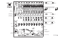
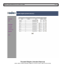
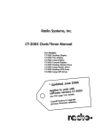
Radio Systems Millenium Digital Console
Livewire® Model
Additional Operating Instructions
601 Heron Drive • Logan Township, NJ 08085
Phone: 856-467-8000 • Fax: 856-467-3044
www.radiosystems.com
Page 2
Radio Systems Millenium-D Livewire Console
Radio Systems Millenium-D Livewire® Console
Installation and Operation Manual
Radio Systems Millenium Digital- Livewire® Broadcast Manual — Part # MAN-MILLCONLIV
Manual Revision 02-29-2012
for serial numbers 100859 and higher
Utilizing Millenium Livewire Digital Console Software V1.3.1.1
New features and modifications in Millenium Livewire version 1.3.1.1
1. Multiple GPIO Livewire profiles supported.
2. Source locking - source name flashes to indicate that it is in use on another Livewire source. Flashing clears
when other user de-selects the source.
3. Iprobe - IP address is now recognized and displayed by Axia “Iprobe” program
4. Scenes a new scene source selection is not loaded (only) onto channels that are on. If the channel is on,
the new scene source (if there is a new source for that channel as part of the new scene) will be displayed
on the lower LCD line and the ON button will flash. Then when that channel is turned off, the scene will load.
5. IP/SUBMASK addresses display and change - IP AND submask addresses are now displayed and can be
changed by holding the last rotary encoder knob down for 10 seconds.
Table of Contents
Livewire Control Board Parts Layout................................................................................. 3
Screen Shots................................................................................................................... 4-13
Creating backstreams (Mix-minus configurations)......................................................... 14
Remote Control - Overview Instructions.......................................................................... 15
Remote Control - GPIO Profiles................................................................................... 16-18
Remote Control - Wiring Diagram..................................................................................... 19
Password Reset Instructions............................................................................................ 20
Copyright 2012 by Radio Systems Design, Inc. All rights reserved. Radio Systems Design, Inc. reserves specification
privileges. Information in this manual is subject to change without notice.
Technical support: +1-856-467-8000 or [email protected]
OUTPUT GROUNDING JUMPERS
JU1
JU2
JU3
JU4
JU5
JU6
JU7
JU8
JU9
JU10
IN
Analog
Output
7
Analog
Output
8
JU39
JU40
J1-J10
Connect left and center pins
for inside ground
Connect center and right pins
for chasis ground
(See Manual for Grounding Instructions)
JU26
JU38
JU25
JU37
Analog
Input
8
JU24
JU36
JU23
JU35
Analog
Input
7
JU22
JU34
JU21
JU33
Analog
Input
6
JU20
JU19
JU32
Analog
Input
5
JU18
JU31
Analog
Input
4
JU17
JU30
JU16
JU29
Analog
Input
3
JU15
7L
JU28
JU14
JU27
Analog
Input
2
JU13
JU12
JU11
J1, J2, J3
Analog
Input
1
J1-J10
JU41
JU42
ANALOG INPUT MONO/STEREO JUMPERS
8R
7R 8L
Analog Output Levels
Connect upper pins on both jumpers
under each channel’s RJ-45 for stereo
(factory default)
JU11/12 thru JU25/26
Connect lower pins on both jumpers
under each channel’s RJ-45 for mono
JU11/12 thru JU25/26
GPIO
Connector
ANALOG INPUT GAIN JUMPERS
From 8 position
selector outputs 5-8
Connect no pins
for unity gain
Digital
Output
7
From 8 position
selector outputs 1-4
JU43
Digital
Output
8
JU44
Digital
Digital
Input
1
JU45
Digital
Input
2
JU46
Digital
Input
3
JU47
Digital
Input
4
Digital
Input
5
JU48
JU49
Digital
Input
6
JU50
Digital
Input
7
JU51
Digital
Input
8
Connect left and center pins
for +20dB gain
Connect center and right pins
for +10dB gain
DIGITAL INPUT GROUNDING JUMPERS
JU52
JU43 thru JU52
JU43 thru JU52
IN
JU53
Activity Connectivity
(Yellow)
(Green)
Parallel
Digital
Output
1
JU54
Parallel
Digital
Output
2
JU55
Parallel
Digital
Output
3
JU56
JU57
Parallel
Digital
Output
4
Parallel
Digital
Output
5
JU58
Parallel
Digital
Output
6
JU59
Parallel
Digital
Output
7
JU60
Parallel
Digital
Output
8
Connect upper pins
for inside ground
Connect lower pins
for chasis ground
(See Manual for Grounding Instructions)
DIGITAL OUTPUT GROUNDING JUMPERS
JU53 thru JU60
JU53 thru JU60
IN
Connect lower pins
for inside ground
Livewire
Connect upper pins
for chasis ground
(See Manual for Grounding Instructions)
100
BaseT
Analog
Grounds
JU61
(Jumpers
Factory Set)
(Jumpers Factory Set)
JU62
JU63 JU64
Factory
Programming
(Jumpers
Factory Set)
RS232
(Factory
Use)
To Upper LiveWire
Control Board
Power, Mute, Timer Signalling
to Output Board
JU65
JU66
RS232
(Factory
Use)
DSP Data & Clocks to Output Board
+5v from Power Supply
MILLENIUM LIVEWIRE CONTROL BOARD
Part # 16144
Radio Systems Millenium-D Livewire Console
1.0 Millenium Source Profile Properties
Define, allocate to various faders and label sources (Axia inputs to the Millenium
Livewire Console).
1.1 Setting Up 2-Way (mix-minus) source profiles
2.0 Millenium Scene Properties
Name and define up to 8 front panel selectable scene presets (and startup default
“scene”).
3.0 Console Outputs (Livewire Sources)
Name, define and label destinations (Millenium Livewire Console outputs to Axia
Livewire).
4.0 Console Inputs (Livewire Destinations) Select and label sources (Axia inputs to the
Millenium Livewire Console).
5.0 Remote Control (GPIO) - 2 screens
5.1 GPIO Overview and Setup Instructions
5.2 GPIO Wiring and Pin-Out Diagram
6.0 Livewire I/O Meters
Level test meters and input gain trims for all sources and destinations.
7.0 Livewire / QoS
Quality of service parameter selections.
8.0 System
IP, password, and software update options.
9.0 Console Node Parts Layout for Physical Connector Locations
Page 4
Page 5
Radio Systems Millenium-D Livewire Console
Millenium Source Profile Properties
Define and allocate to various faders and label sources (Axia inputs to the Millenium Livewire Console)
Radio Systems Millenium-D Livewire Console
Millenium Scene Properties
Name and define up to 8 front panel selectable scene presets (and startup default “scene”)
Page 6
Radio Systems Millenium-D Livewire Console
Console Outputs (Livewire Sources)
Name, define and label destinations (Millenium Livewire Console outputs to Axia Livewire)
Page 7
Radio Systems Millenium-D Livewire Console
Console Inputs (Livewire Destinations)
Select and label sources (Axia inputs to the Millenium Livewire Consoles)
Page 8
Page 9
Radio Systems Millenium-D Livewire Console
GPI Channel Assignment
Select 1-8 Livewire sources that you wish to control (start/stop) or to control (turn on/off) console channels.
Consult details on page 19
Page 10
Radio Systems Millenium-D Livewire Console
GPI Pin Assignments
For each (of eight) GPIO control sources, use this sub-screen to map up to five input and five output physical pins on the
RJ-21 GPIO connector. Note that pins can be multiply assigned to different GPIO ins and outs, but that this is
not recommended. Consult details on page 19.
Page 11
Radio Systems Millenium-D Livewire Console
Livewire / QoS
Quality of service parameter selections
Page 12
Radio Systems Millenium-D Livewire Console
Livewire I/O Meters
Level test meters and input gain trims for all sources and destinations
Page 13
Radio Systems Millenium-D Livewire Console
System
IP, password, and software update options
Note: Default username is “user,” default password is “user.”
See last page of manual for password reset in case of forgotten password.
Page 14
Radio Systems Millenium-D Livewire Console
Millenium - Livewire Console Software
Creating Backstreams (Mix-Minus feeds for 2-way devices)
Gaining Perspective
A Millenium output is a Source (input) to Livewire.
A Millenium input is a Destination (output) of Livewire.
Nomenclature assumes the Livewire network as the point of reference, so;
A Livewire Destination is an Input to the Millenium Console.
A Livewire Source is an output from the Millenium Console.
Connecting the Two-Way Devices
On the source node’s browser page, set a unique Axia channel number (for example, “1021”, where 102 is the last 3 digits
of the node’s IP address, and 1 represents the physical port into which the device is connected).
Define the Source Properties in the Millenium Browser
Check all applicable boxes, including ENABLING the Backwards Feed check box.
Select Backstream Mode
In the Millenium browser Console Output section, set one of the outputs (from Outputs 3-8 - Outputs 1 and 2 are reserved)
in the Backstream (Mix-Minus) Stream Mode. Ensure that the faders chosen have source “1021” (for example) available
on the Source Profile Menu.
Connect the Two-Way Devices’ Input to a Destination Node
On the destination node’s browser page (ie. feeding the codec’s mix-minus), click on the Destination page, then change Type
to “To Source” on the channel whose physical destination is the codec’s mix-minus. Put “1021”(for example) in the
Channel Number field.
Confirm Selection
As a visual verification, when the codec is selected on a Millenum fader, two dots will appear above the Destination
Node’s corresponding output channel.
Utility Bus Programming
Using the Millenium Console Utility Bus setup screen, create the appropriate mix minuses for Utility Bus 1-6.
Millenium console outputs (Sources to Livewire) are factory default configured as:
Livewire - Input #1 from
Console Program Output*
Livewire - Input #2 from
Console Audition Output*
Livewire - Input #3 from
Console Utility Output #1*
Livewire - Input #4 from
Console Utility Output #6*
Livewire - Input #5 from
Console Utility Output #2*
Livewire - Input #6 from
Console Utility Output #7*
Livewire - Input #7 from
Console Utility Output #3*
Livewire - Input #8 from
Console Utility Output #8**
Note: All outputs have been factory hard-wired between the console digital output board and Livewire input board as shown.
The 6 utility outputs have been factory configured as mix-minus outputs so that program is sent “minus” that channels
program audio is sent.
E.G. -Utility output #1 is configured to be program (A or B input / post on-off switch post fader / mono mix) minus the
program output of the first Livewire fader.
Radio Systems Millenium-D Livewire Console
Page 15
Remote Control - “GPIO” Interface
Overview
The Millenium Axia internal console node features a GPIO connector with 16 inputs and 16 outputs. Via programming these
inputs and outputs can be assigned to any network audio source. In this way, the Millenium Livewire console channel can
exercise start/stop control or a device can turn a Millenium console channel on and off when selected as a source on the LCD
display above that fader.
Physical Connectivity
All GPIO inputs and outputs are located on the on-board RJ-21 50-pin male connector. Inputs are opto-isolated and are activated by being “pulled low” (connected to ground). Outputs are open collector and provide a path to ground when activated.
Consult the Illustration on the following page for RJ-21 pin-outs and wiring illustrations
Assigning GPIO via software set-up screens
Source Configuration
An existing audio source connected to the Millenium console or any Livewire node must first be set for GPIO control. On the source profile screen, select BOTH the appropriate GPIO profile and GPIO enable radio button. The GPIO source profile automatically sets up to 5 GPIO input and output functions for each source. These functions
are listed in Illustration XXX on the following page.
GPIO Channel assignment
The Millenium console provided 8 GPIO “ports”, thus allowing up to 8 devices (Livewire audio sources) to have GPIO
connectivity. These devices must be assigned as GPIO channel 1-8 on the Livewire GPIO port assignment
GPIO Pin Mapping
Source GPIO inputs and outputs (up to 5 of each for each source) must be “mapped” to the physical pins on the
GPIO connector. This is accomplished on the GPIO “Pin Mapping” page accessed by clicking the “program pins” link
alongside each Livewire GPIO port channel selection. For each active port channel assign an input or output GPIO
pin by clicking the adjacent radio box.
For example:
If GPIO channel #1 is assigned to a CD player and that CD player’s start control is wired to GPIO port physical output pin#1 and the CD player’s EOM relay is wired to GPIO port physical input #1.
Mapping Livewire port 1 / output pin#1 to GPIO output pin#1 and selecting this CD player on a Livewire console channel will cause the CD player to start when the CD’s console channel is turned on.
Mapping Livewire port 1 / input pin#1 to GPIO input pin#1 and selecting this CD player on a Livewire console channel will cause the console channel to turn off when the CD’s EOM relay fires
Livewire Console Remote Profiles
There are 6 available preconfigured remote profiles. You must choose the appropriate profile when configuring
Livewire Remote Control. The profiles available are below and are detailed on the following pages.
Operator
Producer
Control Room Guest
Studio Guest
Line
Computer Player
Page 16
Radio Systems Millenium-D Livewire Console
GPIO Operator’s Microphone Logic
Name
Pin Type
Notes
INPUTS
ON Command
IN-1 Active Low Input
Turns channel ON
OFF Command
IN-2 Active Low Input
Turns channel OFF
TALK (to Monitor 2) Command IN-3 Active Low Input
Activates the Element TALK to MON2
function and routes mic audio to the Talkback bus
MUTE Command
Mutes channel outputs
IN-4 Active Low Input
TALK (to PREVIEWED SOURCE) IN-5 Active Low Input
Command
Activates the TALK button on
every source currently in
preview and routes mic audio to the Talkback bus
OUTPUTS
ON Lamp
OUT-1 Open Collector to Logic
Common Return
Illuminates when the channel is ON unless TALK or
MUTE is active
OFF Lamp
OUT-2 Open Collector to Logic
Common Return
Illuminates when channel
is OFF
TALK (to Monitor 2) Lamp
OUT-3 Open Collector to Logic
Common Return
Illuminates when TALK TO MON2 is active
MUTE Lamp
OUT-4 Open Collector to Logic
Common Return
Illuminates when MUTE
is active
TALK (to PREVIEWED SOURCE) OUT-5 Open Collector to Logic
Common Return
Illuminates when TALK to Lamp
PREVIEWED SOURCE
is active
GPIO Producer’s Microphone Logic
Name
Pin Type
Notes
INPUTS
ON Command
IN-1 Active Low Input
Turns channel ON
OFF Command
IN-2 Active Low Input
Turns channel OFF
TALK (to Monitor 2) Command IN-3 Active Low Input
Activates the Element TALK to MON2 function and routes mic audio
to the Talkback bus
MUTE Command
Mutes channel outputs
IN-4 Active Low Input
TALK (to PREVIEWED SOURCE) IN-5 Active Low Input
Command
Activates the TALK button on every
source currently in preview and routes
mic audio to the Talkback bus
OUTPUTS
ON Lamp
OUT-1 Open Collector to Logic
Common Return
Illuminates when the channel is ON
unless TALK or MUTE is active
OFF Lamp
OUT-2 Open Collector to Logic
Common Return
Illuminates when channel is OFF
TALK (to Monitor 2) Lamp
OUT-3 Open Collector to Logic
Common Return Illuminates when TALK TO MON2
is active
MUTE Lamp
OUT-4 Open Collector to Logic
Common Return
Illuminates when MUTE is active
TALK (to PREVIEWED SOURCE)OUT-5 Open Collector to Logic
Lamp
Common Return
Illuminates when TALK to PREVIEWED
SOURCE is active
Page 17
Radio Systems Millenium-D Livewire Console
GPIO Control Room Guest Microphone Logic
Name
Pin Type
Notes
INPUTS
ON Command
IN-1 Active Low Input
Turns channel ON
OFF Command
IN-2 Active Low Input
Turns channel OFF
TALK (to CR) Command
IN-3 Active Low Input
Mutes channel outputs and routes source audio to PVW speakers
MUTE Command
Mutes channel outputs
IN-4 Active Low Input
TALK (to SOURCE) Command IN-5 Active Low Input
Activates the TALK button on every source currently in preview and
routes mic audio to the Talkback bus
OUTPUTS
ON Lamp
OUT-1 Open Collector to Logic
Common Return
Illuminates when the channel is
ON unless TALK or MUTE is active
OFF Lamp
OUT-2 Open Collector to Logic
Common Return
Illuminates when channel is OFF
TALK (to CR) Lamp
OUT-3 Open Collector to Logic
Common Return
Illuminates when TALK is active
MUTE Lamp
OUT-4 Open Collector to Logic
Common Return
Illuminates when MUTE is active
TALK (to SOURCE) Lamp
OUT-5 Open Collector to Logic
Common Return
Illuminates when the channel TALK
To SOURCE function is active (Element
only; Smart Surface not used)
GPIO Studio (Monitor 2) Guest Microphone Logic
Name
Pin Type
Notes
INPUTS
ON Command
IN-1 Active Low Input
Turns channel ON
OFF Command
IN-2 Active Low Input
Turns channel OFF
TALK (to CR) Command
IN-3 Active Low Input
Mutes channel outputs and routes
source audio to PVW speakers
MUTE Command
Mutes channel outputs
IN-4 Active Low Input
TALK (to SOURCE) Command IN-5 Active Low Input
Allows an external button to active
channel TALK TO SOURCE
FUNCTION. (Element only;
SmartSurface not used)
OUTPUTS
ON Lamp
OUT-1 Open Collector to Logic
Common Return
Illuminates when the channel is ON
unless TALK or MUTE is active
OFF Lamp
OUT-2 Open Collector to Logic
Common Return
Illuminates when channel is OFF
TALK (to CR) Lamp
OUT-3 Open Collector to Logic
Common Return
Illuminates when TALK is active
MUTE Lamp
OUT-4 Open Collector to Logic
Common Return
Illuminates when MUTE is active
TALK (to SOURCE) Lamp
OUT-5 Open Collector to Logic
Illuminates when the channel TALK
TO SOURCE function is active
(Element only; Smart Surface not used)
Page 18
Radio Systems Millenium-D Livewire Console
GPIO Line Input Logic
Name
Pin Type
Notes
INPUTS
ON Command
IN-1 Active Low Input
Turns channel ON
OFF Command
IN-2 Active Low Input
Turns channel OFF & sends
100 msec STOP pulse
PREVIEW Command
Turns preview ON
IN-3 Active Low Input
RESET Command
IN-4 Active Low Input
“Turns channel OFF, while not sending
a STOP pulse”
READY Command
IN-5 Active Low Input
Illuminates OFF lamp to indicate
source’s readiness
OUTPUTS
ON Lamp
OUT-1 Open Collector to Logic
Common Return
Illuminates when channel is ON
OFF Lamp
OUT-2 Open Collector to Logic
Common Return Illuminates when channel is OFF
and READY is active
PREVIEW Lamp
OUT-3 Open Collector to Logic
Common Return
Illuminates when PREVIEW is ON
START Pulse
OUT-4 Open Collector to Logic
Common Return A 100 msec pulse when the channel
status changes from OFF to ON
STOP Pulse
OUT-5 Open Collector to Logic
Common Return A 100 msec pulse when the channel
status changes from ON to OFF
GPIO Computer Playback Logic
Name
Pin Type
Notes
INPUTS
ON Command
IN-1 Active Low Input
Turns channel ON
OFF Command
IN-2 Active Low Input
STOP pulse
Turns channel OFF & sends 100 msec PREVIEW Command
Turns preview ON
IN-3 Active Low Input
Not Used
IN-4 Active Low Input
“Turns channel OFF, while not sending
a STOP pulse”
READY Command
IN-5 Active Low Input
Illuminates OFF lamp to indicate source’s readiness
OUTPUTS
NEXT Pulse
OUT-1 Open Collector to Logic
Common Return
A 100 mS PULSE sent when ON button is depressed except when initially
turned ON
OFF Lamp
OUT-2 Open Collector to Logic
Common Return
Illuminates when channel is OFF
and READY is active
PREVIEW Lamp
OUT-3 Open Collector to Logic
Common Return
Illuminates when PREVIEW is ON
START Pulse
OUT-4 Open Collector to Logic
Common Return A 100 mS PULSE sent when channel is first turned ON
STOP Pulse
OUT-5 Open Collector to Logic
Common Return A 100 mS PULSE sent when channel is first turned OFF
Page 19
Radio Systems Millenium-D Livewire Console
Millenium Livewire Console
Output Wiring
“GPIO” Wiring Pin-Out (controlGPI
signals from the console)
680 Ohms
1
2
3
4
5
6
7
8
9
10
11
12
13
14
15
16
17
18
19
20
21
22
23
24
25
26
27
28
29
30
31
32
33
34
35
36
37
38
39
40
41
42
43
44
45
46
47
48
49
50
Output #1
Output #2
Output #3
Output #4
Output #5
Output #6
Output #7
Output #8
Output #9
Output #10
Output #11
Output #12
Output #13
Output #14
Output #15
Output #16
Input #1
Input #2
Input #3
Input #4
Input #5
Input #6
Input #7
Input #8
Input #9
Input #10
Input #11
Input #12
Input #13
Input #14
Input #15
Input #16
Ground
Ground
Ground
Ground
Ground
Ground
Ground
Ground
Ground
Ground
Ground
Ground
Ground
Ground
Ground
Ground
+15 Volts
+15 Volts
Remote start of source with
open collector or opto-isolated
(push-low) input terminal
GPI Input Wiring
(control signals to the console)
n.o. switch
Remote signaling from
source with open collector or
opto-isolated (pull-to-ground)
output terminal
LED
Use of 66B punch block with integrated RJ-21
female connector is recommended. Specify RS Part
#11616 with companion RS Part #RJ21RC-010 10'
RJ-21 male to male 25-pair cable.
50-Pin internal console node “GPIO” connector
25
1
50
26
16 Inputs - Pull to Ground
Input #1 - Pin 34
Input #2 - Pin 9
Input #3 - Pin 35
Input #4 - Pin 10
Input #5 - Pin 36
Input #6 - Pin 11
Input #7 - Pin 37
Input #8 - Pin 12
Input #9 - Pin 38
Input #10 - Pin 13
Input #11 - Pin 39
Input #12 - Pin 14
Input #13 - Pin 40
Input #14 - Pin 15
Input #15 - Pin 41
Input #16 - Pin 16
16 Outputs - Open Collector
Output #1 - Pin 26
Output #2 - Pin 1
Output #3 - Pin 27
Output #4 - Pin 2
Output #5 - Pin 28
Output #6 - Pin 3
Output #7 - Pin 29
Output #8 - Pin 4
Output #9 - Pin 30
Output #10 - Pin 5
Output #11 - Pin 31
Output #12 - Pin 6
Output #13 - Pin 32
Output #14 - Pin 7
Output #15 - Pin 33
Output #16 - Pin 8
GND Pins 17, 18, 19, 20, 21, 22, 23 ,24, 42, 43, 44, 45, 46, 47, 48, 49
+15 Volts Pins 25, 50 (each is individually current limited)
Page 20
Radio Systems Millenium-D Livewire Console
Password Reset for Livewire Browser Screens
Millenium Network Console Password Reset for Livewire Browser Screens
• Locate the gray Millenium RS-232 adapter shipped with your console originally; it is a DB-9 to RJ45 adapter (pinouts below).
Use a standard Ethernet patch cord of sufficient length to go between your PC and the console.
• Plug in DB-9 side of the adapter to your PC
• Plug the RJ45 side (using the above-mentioned cable) to the AUX RS232 port on the Livewire audio board.
This port is located directly behind the MAIN port
• Start a HyperTerminal (hypertrm) connection with the following characteristics:
• 19200 Baud
• 8/N/1 bits
• None for Flow Control
• ANSI for language
• Turn off Local Echo
• Re-boot the Millenium console once the HyperTerminal connection is made. You should see a boot sequence scroll
on your PC screen.
• Once the console boots, press ENTER a few times on your PC to get to a command prompt
• Type: “cp /etc/default/passwd /etc/config/”
• Do not type the quotes (“) and notice the space between passwd and /etc
• This will reset the password to “user”
DB9 to
Source Gear
DB Pin #
Function
5
Ground
Receive (RX)
Transmit (TX)
3
2
In/Out
RJ-45
to
Console
5
4 3
9
8
2
7
1
6
Rear of Connector Shown
Adapter Connector is a DB9 female
(Mating Connector on the equipment is a DB9 male)
Complete Millenium Digital RS-232 Data Remote Control Functions
DB-9 PIN #
1
2
3
4
5
6
7
8
9
Function
N/C
Transmit (TX)
Receive (RX)
N/C
Signal Ground
N/C
N/C
N/C
N/C
Input/Output
Output
Input