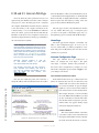
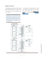
1
IP-Intercom System Installation & User’s Guide Manual Version 1.2.1 Aug 2010 IP-Intercom Software 1.2.5 and up IMPORTANT NOTE: Axia Livewire devices are intended for use with an Ethernet Switch that supports multicast and QoS (Quality of Service). On a non-switched Ethernet hub, or a switch that is not enabled for multicast, this will result in network congestion that could disrupt other network activity. Important Safety Information To reduce the risk of electrical shock, do not expose this product to rain or moisture. Keep liquids away from the ventilation openings in the top and rear of the unit. Do not shower or bathe with the unit. Caution USA Class A Computing Device Information To User. Warning: This equipment generates, uses, and can radiate radio-frequency energy. If it is not installed and used as directed by this manual, it may cause interference to radio communication. This equipment complies with the limits for a Class A computing device, as specified by FCC Rules, Part 15, Subpart J, which are designed to provide reasonable protection against such interference when this type of equipment is operated in a commercial environment. Operation of this equipment in a residential area is likely to cause interference. If it does, the user will be required to eliminate the interference at the user’s expense. NOTE: Objectionable interference to TV or radio reception can occur if other devices are connected to this device without the use of shielded interconnect cables. FCC rules require the use of only shielded cables. Canada Warning: “This digital apparatus does not exceed the Class A limits for radio noise emissions set out in the Radio Interference Regulations of the Canadian Department of Communications.” “Le present appareil numerique n’emet pas de bruits radioelectriques depassant les limites applicables aux appareils numeriques (de les Class A) prescrites dans le Reglement sur le brouillage radioelectrique edicte par le ministere des Communications du Canada.” The installation and servicing instructions in the manual are for use by qualified personnel only. To avoid Electric Shock, do not perform any servicing other than that contained in the operating instructions unless you are qualified to do so. Refer all servicing to qualified personnel. Electrical Warning To prevent risk of electric shock: Disconnect power cord before servicing. This equipment is designed to be operated from a power source that includes a third “grounding” connection in addition to the power leads. Do not defeat this safety feature. In addition to creating a potentially hazardous situation, defeating this safety ground will prevent the internal line noise filter from functioning. Ventilation Warning Axia IP-Intercom devices use convection cooling. Do not block the ventilation openings in the side or top of the units. Failure to allow proper ventilation could damage the unit or create a fire hazard. Do not place the unit on a carpet, bedding, or other materials that could interfere with the rear and top panel ventilation openings. Customer Service We support you... By Phone/Fax in the USA. • Customer service is available from 9:30 AM to 6:00 PM USA Eastern Time, Monday through Friday at +1 216.241.7225. Fax: +1 216.241.4103. The 24-hour Telos/Omnia/Axia support line is +1 216.622.0247. By E-Mail. • The address is [email protected]. Via World Wide Web. • The Axia Web site has a variety of information which may be useful for product selection and support. The URL is http://www.AxiaAudio.com. Feedback We welcome feedback on any aspect of Axia products or this manual. In the past, many good ideas from users have made their way into software revisions or new products. Please contact us with your comments. Updates The operation of Axia IP-Intercom is determined largely by software. Periodic updates may become available - to determine if this is the case check our web site. Contact us to determine if a newer release is more suitable to your needs. Our electronic newsletter has announcements of major software updates for existing products, as well as keeping you up to date on the latest Axia, Telos, and Omnia product releases. You may subscribe to update notifications here: http://www.axiaaudio.com/signup.htm Trademarks Axia Audio 1241 Superior Ave. Cleveland, OH 44114 USA +1 (216) 241-7225 [email protected] Copyright © 2010 by TLS Corporation. Published by Axia Audio. We reserve the right to make improvements or changes in the products described in this manual, which may affect the product specifications, or to revise the manual without notice. All rights reserved. Version 1.2.1 Aug 2010 Introduction • iii Telos Systems, Axia Audio, Livewire, the Livewire Logo, the Axia logo, SmartSurface, Element, SmartQ, Omnia, the Omnia logo, and the Telos logo, are trademarks of TLS Corporation. All other trademarks are the property of their respective holders. Notice About This Manual All versions, claims of compatibility, trademarks, etc. of hardware and software products not made by Axia mentioned in this manual or accompanying material are informational only. Axia makes no endorsement of any particular product for any purpose, nor claims any responsibility for operation or accuracy. Warranty This product is covered by a five year limited warranty, the full text of which is included in the rear section of this manual. Service You must contact Axia before returning any equipment for factory service. Axia will issue a Return Authorization number, which must be written on the exterior of your shipping container. Please do not include cables or accessories unless specifically requested by the Technical Support Engineer at Axia. Be sure to adequately insure your shipment for its replacement value. Packages without proper authorization may be refused. US customers please contact Axia technical support at +1 (216) 241-7225. All other customers should contact their local representative to arrange for service. This manual covers the details of the Axia IP-Intercom products. This document assumes that you are familiar with Livewire’s basic concepts, as outlined in the our Introduction to Livewire: IP-Audio System Design Reference and Primer manual. If you have not done so, please review that material first. In it we explain the ideas that motivated Livewire and how you can use and benefit from it, as well as nitty-gritty details about wiring, connectors, and the like. Since Livewire is built on standard networks, we also help you to understand general network engineering so that you have the full background for Livewire’s fundamentals. After reading Introduction to Livewire you will know what’s up when you are speaking with gear vendors and the network guys that are often hanging around radio stations these days. As always, we welcome your suggestions for improvement. Contact Axia Audio with your comments: Axia Audio, a Telos Company 1241 Superior Avenue Cleveland, Ohio 44114 USA Phone: +1.216.241.7225 Web: www.AxiaAudio.com E-Mail: [email protected] Introduction • iv We strongly recommend being near the unit when you call, so our Support Engineers can verify information about your configuration and the conditions under which the problem occurs. If the unit must return to Axia, we will need your serial number, located on the rear panel. Version 1.2.1 Aug 2010 Table of Contents Console-Mounted Intercom Stations . . . . . . . . . 10 Customer Service . . . . . . . . . . . . . . . . . iii Warranty . . . . . . . . . . . . . . . . . . . . . . iv Chapter Three: Advanced Programming . . . . . . . . 13 Service . . . . . . . . . . . . . . . . . . . . . . . iv Assigning an IP Address . . . . . . . . . . . . . . . 13 About This Manual . . . . . . . . . . . . . . . . . iv IC.20 and IC.1 Intercom Web Pages . . . . . . . . . 14 A Note from the President of Axia . . . . . vii Home Page . . . . . . . . . . . . . . . . . . . . . 14 Intercom Configuration Page . . . . . . . . . . . 14 Chapter One: Introducing Axia IP-Intercom . . . . . 1 External Sources Page . . . . . . . . . . . . . . . 16 Overview . . . . . . . . . . . . . . . . . . . . . . . 1 Key Assign Page (IC.20) . . . . . . . . . . . . . . 17 IP-Intercom Stations: Front Panel . . . . . . . . . . 2 Key Assign Page (IC.1) . . . . . . . . . . . . . . 18 Front Panel Connectors . . . . . . . . . . . . . . 2 Livewire GPIO Page . . . . . . . . . . . . . . . . 18 Intercom Channel Controls . . . . . . . . . . . . 2 Network and Quality of Service Page . . . . . . . 20 Talk . . . . . . . . . . . . . . . . . . . . . . . 2 System Configuration Page . . . . . . . . . . . . 22 Listen . . . . . . . . . . . . . . . . . . . . . . 2 Factory Reset (OLED panels only) . . . . . . . . . . 24 OLED Display . . . . . . . . . . . . . . . . . 2 Display Tests . . . . . . . . . . . . . . . . . . . . . 24 Volume . . . . . . . . . . . . . . . . . . . . . 2 OLED Front Panel Test . . . . . . . . . . . . . . 24 Mute Microphone . . . . . . . . . . . . . . . . 2 Legendable Buttons Front Panel Test . . . . . . . 24 Mute Speaker . . . . . . . . . . . . . . . . . . 3 IP Address . . . . . . . . . . . . . . . . . . . . . . . 25 Select . . . . . . . . . . . . . . . . . . . . . . 3 Intercom Expansion Configuration . . . . . . . . . . 25 Group . . . . . . . . . . . . . . . . . . . . . . 3 IC.20 with IC.10X . . . . . . . . . . . . . . . . . 25 Assign/Enter . . . . . . . . . . . . . . . . . . 3 Element IP-Intercom Modules . . . . . . . . . . . . 26 CALLSTACK Controls (20-Station Panel) . . . 3 Intercom Configuration . . . . . . . . . . . . . . 26 Keypad (20-Station Panel) . . . . . . . . . . . 3 Channel Assignment (10 and 20 Ch) . . . . . . . 28 Filmcap Buttons (Programmable) . . . . . . . 3 Channel Assignments (10-Btn Film Cap) . . . . . 28 Livewire Status Indicators . . . . . . . . . . . . . 3 GPIO Configuration . . . . . . . . . . . . . . . . 28 IP-Intercom Stations: Rear Panel . . . . . . . . . . . 4 Intercom Livewire Sources . . . . . . . . . . . . . 29 Chapter Two: Setup and Operation . . . . . . . . . . . 7 Appendix A: Unbalanced Connections . . . . . . . . 31 Individual Channel Controls . . . . . . . . . . . . . 7 Appendix B: Connecting GPIO . . . . . . . . . . . . 33 Talk . . . . . . . . . . . . . . . . . . . . . . . 7 Appendix C: Specifications and Warranty . . . . . . 41 Listen . . . . . . . . . . . . . . . . . . . . . . 7 Axia System Specifications . . . . . . . . . . . . . . 41 Talk/Listen . . . . . . . . . . . . . . . . . . . 7 Axia Limited Warranty . . . . . . . . . . . . . . . . 43 OLED Display (Individual Channels) . . . . . 7 Other Controls . . . . . . . . . . . . . . . . . . . . 7 OLED Display (CALLSTACK) . . . . . . . . . 7 Volume . . . . . . . . . . . . . . . . . . . . . 8 Mute Speaker (MUTE SPKR) . . . . . . . . . 8 Select . . . . . . . . . . . . . . . . . . . . . . 8 Group (20-Station Panel) . . . . . . . . . . . 9 Assign (20-Station Panel) . . . . . . . . . . . . 9 CALLSTACK (20-Station Panel) . . . . . . . . 10 Keypad (IC.20 only) . . . . . . . . . . . . . . 10 Film-Cap Buttons (IC.1 only) . . . . . . . . . 10 Version 1.2.1 Aug 2010 Introduction • v Mute Microphone (MUTE MIC) . . . . . . . . 8 Microphone opens. Speech, in tones soft and mellow. Introduction • vi A new broadcast day. Version 1.2.1 Aug 2010 20 years ago, I designed my first broadcast console for PR&E. I look back on that time with great fondness; we were building bullet-proof boards for the world’s most prestigious broadcasters, making each new console design bigger and fancier to accommodate a wider variety of source equipment and programming styles. The console was the core of the studio; all other equipment was on the periphery. Then things changed: the PC found its way into broadcast audio delivery and production. At first, PC audio applications were simple, used only by budget stations to reduce operating expenses. But soon the applications evolved and were embraced by larger stations. Slowly, the PC was taking center stage in the radio studio. Like many, I was captivated by the PC. Stations retired carts, phonographs, open-reel decks, cassettes — even more modern digital equipment such as DAT and CD players, replacing all with PC apps. Client/server systems emerged and entire facilities began using PCs to provide most – or all – of their recorded audio. Yet consoles continued to treat PCs as nothing more than audio peripherals. I knew that we console designers were going to have to rethink our designs to deal with computer-centric studios. During this time, traditional broadcast console companies began producing digital versions. But early digital consoles were nearly identical in form and function to their analog predecessors. It took a fresh look from a European company outside broadcasting to merge two products – audio routing switchers and broadcast consoles – into a central processing engine and attached control surface. Eventually nearly every console and routing switcher company followed suit, and a wide variety of digital “engines” and control surfaces flooded the market. But, advanced as these integrated systems were, they still handled computer-based audio sources like their analog ancestors. Sure, the router and console engine were now integrated, but the most important studio ele- ment – the PC – was stuck in the past, interfaced with 100-year-old analog technology. The PC and console couldn’t communicate in a meaningful way – strange, considering that PCs everywhere were being networked, fast becoming the world’s most popular and powerful communication tool. Then a group of Telos engineers developed a method of using Ethernet to network real-time audio devices, allowing computers and consoles, controllers and peripherals to interact smoothly and intelligently. Powerful, flexible networks had finally come to our studios. As with the transition from carts to computers, the benefits are many and impressive. A few networked components can replace routing switchers, consoles, processing peripherals, sound cards, distribution amps, selector switches and myriad related devices. This deceptively simple networked system costs a fraction of other approaches, yet has capabilities surpassing anything else. The system is modular and can be used to perform discrete functions in a traditional environment. Concurrently, it easily scales to serve both the humblest and the very largest of facilities. Console, router, and computer work in harmony. So, equipped with this new technology and countless ideas, we launch Axia, the newest division of Telos. Axia is all about delivering innovative networked audio products to future-minded broadcasters. On behalf of our entire team, I welcome you as a charter client. Axia is the culmination of nearly 40 manyears of some of the most ambitious R&D ever applied to the radio industry. And this is only the beginning. We have more products, innovations, and partnerships in the pipeline. You already know your Axia system is unlike anything else. So it shouldn’t be surprising that your new system is loaded with new thinking, new approaches, and new ideas in virtually every conceivable area. Some concepts will challenge your traditional ideas of studio audio systems, but we’re certain that once you have experienced the pleasures of the networked studio, you’ll never want to go back. And now, for something completely different... Michael “Catfish” Dosch Version 1.2.1 Aug 2010 Introduction • vii A Note From The President of Axia Who is so attuned that he may perceive the sound Introduction • viii of one bit dropping? Version 1.2.1 Aug 2010 Chapter One: Axia’s IP-Intercom products may operate as a standalone intercom system. The IP-Intercom system also integrates seamlessly with console and routing functions of any existing Axia Livewire network. Broadcasters have already discovered the advantages of using Axia networks. Less cost, less wiring and less setup time are just a few of the benefits gained from using Ethernet for real-time audio routing. Now, broadcast intercom systems benefit from those same advantages. Axia IP-Intercom Networks lower installed cost by using CAT-5 and standard switched Ethernet for instant communication between multiple stations. And if you already have an Axia network in your broadcast facilities, deployment is even easier. Axia IPIntercoms plug right into Livewire networks for tight integration with Axia broadcast consoles and routing systems; console operators’ existing console microphone and preview speaker are used to provide seamless intercom communications right from the board. IP-Intercom Overview The family of Axia IP-Intercom products includes several models of rack-mounted panels and consolemounted modules as well as a software intercom panel and desktop versions (coming soon). Rackmount Stations: • IC.20 20-station panel with OLED displays • IC.10X 10-station expansion panel with OLED displays • IC.1 10-station panel with user-labeled buttons Many of us are familiar with Axia’s Element console and know that every Element surface fader module has built-in talkback to/from any connected source. These standard communication capabilities are more advanced than those normally found on high-end many broadcast consoles and will satisfy most intercommunication requirements found in radio. Some more complex operations such as broadcast news or live productions may require more extensive features. The enhanced intercom capabilities needed in these demanding environments is provided by Axia’s rack-mount intercom stations as well as drop-in Element modules and a software IP-Intercom station (coming soon). Axia IP-Intercom can also be integrated into a facility that consists of only Livewire audio and GPIO nodes. Axia IP-Intercom equipment introduces AEC (Advanced Echo Cancellation) technology licensed from Germany’s Fraunhofer Institute (the inventors of MP3). AEC is a revolutionary echo-cancellation technology which enables full duplex operation without the use of headphones. AEC allows simultaneous Talk and Listen without feedback or comb-filtering. It is no longer necessary to mute or dim the Listen loudspeaker when Talking. NOTE: Only approved and properly programmed Ethernet switches incorporating the proper Multicast and QoS standards should be used. See www.AxiaAudio.com/switches/ for details. Element Console Stations: • 20-station panel with OLED displays • 10-station panel with OLED displays • 10-station panel with user-labeled buttons Desktop Intercom Stations and SoftCom Intercom Station for Windows are currently under development and will be released in the near future. Version 1.2 July 2010 1: Introducing IP-Intercom • 1 Introducing Axia IP-Intercom IP-Intercom Stations: Front Panel The rackmounted Livewire IP-Intercom stations incorporate a number of front panel connectors, controls and indicators to allow the operator to operate the system quickly and confidently. Front and rear panel views are shown for the 20-station OLED display and the 10-station film-cap user-legendable stations. The Element console versions of these stations incorporate the same controls in slightly different physical layouts. Intercom Channel Controls This section provides only some basic information on the device controls. Please refer to Chapter 2: Setup and Operation for an in-depth discussion of the operation of the IP-Intercom panels. Talk This button may be used in momentary or latch modes. You may press and hold the Talk button to talk. You may also tap to latch Talk mode and tap again to release Talk mode. 1: Introducing IP-Intercom • 2 Front Panel Connectors Microphone Jack This jack is used for a panel-mount microphone with a 1/4 inch Tip-Ring-Sleeve connector. One popular intercom microphone is the Telex MCP-90-8. Listen Press and hold the Listen button to listen momentarily. Tap the Listen button to latch Listen mode and tap again to release Listen mode. Intercom Headset Connector This is a 4-pin XLR-M connector used to connect an industry standard intercom headset that incorporates both a microphone and a headphone. One example is the Production Intercom SMH210 Single Muff Headset. There are numerous other manufacturers of these headsets that all use the following 4-pin wiring convention: Pin 1: Mic common Pin 2: Mic hot Pin 3: Headphone common Pin 4: Headphone hot (mono) OLED Display This 10-character display shows the Label of the channel assigned to the adjacent Talk and Listen buttons. Volume The rotary Volume control is used to adjust the overall level of the loudspeaker audio. Mute Microphone Tapping the Mute Microphone button alternately enables and disables the microphone ensuring privacy if necessary. Figure 1-1: IC.20 - Front Panel Callouts Version 1.2 July 2010 Mute Speaker Tapping the Mute Speaker button alternately enables and disables the audio from the local speaker. sheet software. Create the 1/2 inch square labels for these buttons. Use your fingers to pop off the button cap and insert your label behind the clear button cap. Select The Select control is used to scroll through various menu options and to and select from pending calls. See the section that follows on the CALLSTACK channel. Livewire Status Indicators Group The Group button enables the user to talk to multiple users with one press. Net When illuminated continuously, this LED represents the presence of a live Ethernet link to another Ethernet 100Base-T device. If no Ethernet link is present, this LED flashes slowly. CALLSTACK Controls (20-Station Panel) This channel is used for monitoring and calling stations that are not assigned to a specific Talk/Listen channel on the user’s panel. See Chapter 3 for details. Keypad (20-Station Panel) A 12-button telephone-style dialing keypad will be used for features to be added in the future. Filmcap Buttons (Programmable) The model IC.1 rackmount 10-key Intercom station, shown in Figure 1-2, features 10 buttons that are used in the same manner as the Talk/Listen buttons on the 20-channel unit. These functions are programmed in the web browser configuration. Button caps are manually labelled using your favorite word processor or spread- Sync and Master Only one of these two LEDs should be illuminated. The SYNC LED indicates the receipt of clock information from another (Master) Livewire device. The MASTER LED indicates that this device is acting as the master clock source for the Livewire network. Livewire This LED indicates that Livewire traffic is present on the connected Ethernet segment. NOTE: Axia console mounted IP-Intercom stations use the Control Room Microphone and the Preview speaker instead of the mic/line inputs and front panel speaker of the rack-mount models discussed here. Please refer to Chapter 2: Setup and Operation for detailed descriptions of the IP-Intercom station controls. Figure 1-2 IC.1 Front Panel Controls Version 1.2 July 2010 1: Introducing IP-Intercom • 3 Assign/Enter This button is used to assign devices to the IP-Intercom Group. It doubles as the “enter” key. See Chapter 2 for details on Group functions. Four LEDs indicate the status of the Livewire and Ethernet connections, as well as system synchronisation as follows: IP-Intercom Stations: Rear Panel All rackmounted intercom stations have identical rear panel configurations with the exception of the 10-station intercom expander. This expansion unit has only a Livewire jack, ID button and AC connector. The rear panel of the 20-station panel is illustrated in Figure 1-4 and described in the following section. Livewire (100 Base-T) Connector This connector is for connection to an approved Ethernet switch. It has two integral LEDs. The green “Link” LED indicates the presence of a live signal (same as the front panel “NET” LED). The “Activity” LED indicates that Ethernet packets are being sent or received over the link. IMPORTANT NOTE: Axia IP-Intercom stations are intended for use with an Ethernet Switch that supports multicast and QOS (Quality of Service). If you attempt to use them with nonswitched Ethernet hubs, or a switch that is not enabled for multicast, you will experience network congestion that could disrupt other network activity. Information on qualified Ethernet switches is found here: http://www.axiaaudio. com/switches/default.htm 1: Introducing IP-Intercom • 4 ID Button This recessed switch allows you to assign an IP address to a new unit. An IP address is required so you can use your web browser to setup the advanced features of the IP-Intercom panel. When the ID button is pressed, you are prompted to enter an IP address and subnet mask from the front panel controls. Pressing this button also triggers the IP-Intercom panel to identify itself and request an IP address from a BootP server on the Ethernet network (more on this later). 1 8 Figure 1-3: RJ-45 Pin Locations IMPORTANT NOTE: Axia recommends using balanced audio for analog audio connections. If unbalanced sources are to be connected to these inputs, we strongly recommend using a balun (transformer) or balanced-to-unbalanced buffer amplifier at the source device. Such devices are readily available, for example the StudioHub “Match Jack”. RJ-45 ANALOG LINE CONNECTORS Pin Function: 1 Left Channel + 2 Left Channel - 3 Right Channel + (on output only) 4 Not Connected 5 Not Connected 6 Right Channel - (on output only) 7 Not Connected 8 Not Connected Three-pin XLR connectors are also available for mono line level analog audio connection in and out of the IP-Intercom rear panel. Industry standard pin conventions are followed. Pin 1: Ground (optional connection) Pin 2: Analog Audio + Pin 3: Analog Audio - Audio Input and Output Connectors Line Level Analog Audio All RJ-45 line-level input and output connections to IP-Intercom stations are dual channel connectors. Each pair of audio inputs on the Analog Line shares an 8-position / 8-pin RJ-45 modular jack. The connector pin functions are shown in the table that follows. Inputs are mono - left channel only. Outputs are dual channel mono. Microphone Input A 3-pin XLR-F connector is supplied for a balanced microphone input to the system. Phantom Power is enabled from the web page configuration. Pin 1: Ground (Mic shield) Pin 2: Microphone + Pin 3: Microphone - Version 1.2 July 2010 Figure 1-4: IC.20 - Rear Panel Callouts Analog Line Input Characteristics • Level: +4 dBu nominal (+24 dBu clip point) • Impedance : >/= 10 K Ohm balanced. IP-Intercom GPIO Connector Pinouts Pin Function: 1 Listen Active Lamp Analog Microphone Input Characteristics • Level: -83 to -28 dBu nominal, adjustable in 1 dB steps • Headroom: 20 dB above nominal • Impedance: ≥ 4 KOhm balanced 2 Analog Output Characteristics • Level: +4 dBu nominal (+24 dBu clip point) • Impedance: < 50 Ohm 6 3 Ring Lamp 4 Mic Mute Lamp 5 Line Active Lamp 7 8 9 10 GPIO Port 11 The rear panel contains a 15-pin control connector with a logic input to mute the internal speaker, a logic output to dim/mute the console speakers when the intercom microphone is unmuted as well as a logic output to signal when the intercom is being signaled (ringing). A logic output is also provided, which follows the front panel Line-Active warning LED. The GPIO pin assignment are shown in the table that follows. 12 AC (Mains) Power These signals are available as electrical signals on the rack mount unit (or other Livewire GPIO ports) and as software GPIO on all intercom channels. The AC receptacle connects mains power to the unit with a standard IEC power cord. The power supply has a “universal” AC input, accepting from 90 to 240 VAC, 47-63 Hz. Fuses are located inside the chassis. Mute Preview/Speaker Command 13 14 15 Version 1.2 July 2010 1: Introducing IP-Intercom • 5 Note: All microphone and line inputs are internally summed. All outputs are dual-channel mono. Featureless paper this page would have been empty 1: Introducing IP-Intercom • 6 save for this haiku. Version 1.2 July 2010 Setup and Operation Chapter 1: Introducing Axia IP-Intercom described the physical connections to the IP-Intercom stations. This chapter will discuss the operation of the IP-Intercom stations when used as a standalone system or in conjunction with your Element console and Livewire audio nodes. Please be sure to read Chapter 3: Advanced Programming so you will understand how you assign the IP address and Livewire channel numbers to your IP-Intercom station. Chapter 3 also describes the web page interface and the advanced features and capability of your IP-Intercom system. Individual Channel Controls Talk This key may be used in momentary or latching modes. To use it as a momentary PTT (push-to-talk) switch, you may press and hold the Talk key to talk. If you want to us it as a latching control, you can tap to latch Talk mode and tap again to release Talk mode. The red Talk LED illuminates during Talk Mode, or when the remote station associated with that key is listening. The Talk LED may flash to indicate a fault (attempt to communicate with faulty or disconnected panel, route is locked out by studio IFB, function is overridden by another station, system failure prohibits completing route, etc.) PRIVACY NOTE: If a remote user is assigned to one of your intercom channels and that user presses his Listen key (corresponding to your station), the Microphone LED will indicate solid RED. This means that the remote user is listening to you. This is desirable if you want fast, hands-free operation. If you want to ensure your privacy - be sure to press your Mute Mic key. The yellow Listen LED illuminates during Listen Mode when an assigned remote station is calling the local station. The Listen LED will continue to flash for 5 seconds (by default) after the remote user has disconnected to indicate who has recently called. This is useful in a busy operation where there are many short calls making it difficult to keep track of who has spoken to you while you are concentrating on other tasks. Talk/Listen If you want to initiate a full-duplex hands-free conversation with a remote station, simply press both Talk and Listen keys. As long as the remote microphone is not muted, the two-way communication can proceed without any action on the part of the remote user. Remember communication among IP-Intercom stations is always full-duplex. Hands-free operation may not be available when communicating with third-party equipment that does not support full-duplex operation. OLED Display (Individual Channels) This 10-character display will show the Label of the Source that is assigned to the adjacent Talk and Listen buttons. The upper part of the display refers to the buttons above the display and the lower part of the display refers to the buttons below the display. If you have configured the channel with an Alternate Label, that alternate name will be displayed. Other Controls OLED Display (CALLSTACK) This high contrast OLED (Organic Light Emitting Diode) display is context dependent and is used to display many different parameters in conjunction with the Version 1.2 July 2010 2: Basic Setup and Operation • 7 Chapter Two: Listen In a manner identical to the Talk button, this key may also be used in two different ways. You may press and hold the Listen key to listen momentarily. You may also tap the Listen key to latch Listen mode and tap again to release Listen mode. You may also press multiple keys and listen on more than one channel if desired. Figure 2-1: IC.20 Front Panel Controls 2: Basic Setup and Operation • 8 Select control and Assign/Enter key. Those controls are fully described in subsequent sections. Volume The rotary Volume control performs three functions. • It is used to adjust the overall level of the loudspeaker audio by simply rotating the control. • When the Volume Control is rotated while pushing a Listen button, it adjusts the audio level of only that source on the panel loudspeaker without affecting the levels presented for that source elsewhere in the system. When a channel is removed from listen mode, the default level is restored. • The headphone level can be controlled by pushing the Volume control encoder and adjusting the volume while pushed. When released, normal operation will resume. Mute Microphone (MUTE MIC) Tapping the Mute Microphone key alternately enables and disables the microphone. The red LED illuminates when the microphone is muted and extinguishes when the microphone is active. Whenever the intercom station is powered up, the analog output and Livewire source may be active. If you want the freedom of hands-free communication with other stations, make sure the Mute Mic LED is not illuminated. Alternately, to ensure your privacy, you should use the Mute Microphone function. Mute Speaker (MUTE SPKR) Tapping the Mute Speaker button alternately enables and disables the audio from the local speaker. The red LED illuminates when the speaker is muted and extinguishes when the local speaker is active. Note that the speaker may also be muted by a contact closure to the GPIO port input 2 (pin 12). Select The Select control is used for several functions: • The Select control is used in injunction with the Assign/Enter key to scroll and select from options in the Assign, Shift and Status menus. See the section on the Assign key for the details of Figure 2-2: IC.10X - Expander Chassis Version 1.2 July 2010 • • these menus. The Select control can also scroll and select incoming calls from stations not assigned to a local channel. See the section that follows on the CALLSTACK channel. Pressing the Select control will toggle between the main and alternate Channel Labels. This switches all labels on keys and menus. If an alternate label is not available, the main label will remain on the display The Select control is used in combination with the Assign/Enter key to navigate menus. Pressing the Assign key performs the “enter” function thus choosing the highlighted option. Assign (20-Station Panel) The Assign key is used in conjunction with the Select control for several functions. The Assign key works like an “enter” key to: • Assign channels to the Talk/Listen buttons. • Program the channels that are assigned to the Group button (described previously). Figure 2-3: IC.20 Memu Tree • • Choose pre-programmed Shift pages. Choose other parameters in IC.20 menus in conjunction with the Select control. The IC.20 Menu Tree is illustrated in Figure 2-3. The Select control is used to scroll through the menu options and the Assign/Enter key is used to choose the highlighted option. Menu Tree descriptions follow: • Home Page - lists the CALLSTACK (incoming call requests) plus the ASSIGN, SHIFT and STATUS options. • ASSIGN - takes you to a list of available intercom users that can be assigned to dedicated intercom channels. Scroll with the Select control and press the Assign key to make a selection. Then press the Microphone key on the channel to which you wish to assign the new user. • SHIFT - takes you to a list of presets, referred to as Shift Pages. These preset Shifts are used to load up entire 20-channel key configurations. The Select control is used to scroll the list and the Assign key is used to make your choice. • STATUS - takes you to a page that will list various status parameters. The current version of the software displays the IC.20 Intercom Label and the temperature (degrees C) of the unit. Version 1.2 July 2010 2: Basic Setup and Operation • 9 Group (20-Station Panel) The Group button enables the user to talk to multiple sources with one press. It is used in two different ways: • The Group button is used as a Group Talk key to talk to your station group (discussed below) in momentary or latching modes. To use Group as a momentary PTT (push-to-talk) key, simply press and hold the Group button. If you want to us this as a latching control, you can tap to latch Group Talk mode and tap again to release Group Talk mode. • Pressing the Assign button and then the Group button will enter Group Assignment mode, at which point the Group LED will flash. Tap any number of channel Listen keys that you wish to join into the group. Tap any number of previously selected Listen buttons that you wish to remove from the group. Talk and Listen LED indicators illuminate to show group assignment state. Tap the Group button to leave assignment mode and its LED extinguishes. Figure 2-4: IC.1 Front Panel Controls 2: Basic Setup and Operation • 10 • In all menus, selecting Back will take you back to the Home Page. CALLSTACK (20-Station Panel) This CALLSTACK channel (found only on the 20-station rackmount panel and the 20-station Element console module) is used for monitoring and calling stations that are not assigned to a specific Talk/Listen channel on the user’s panel. The OLED lists up to four ringing, active and last completed calls. Press Talk to talk to the present source displayed. You can use the Select control to scroll through the call list. • The Listen LED flashes yellow when the local user is being called by a station not assigned to one of the Talk/Listen channels on the called station panel, and continues to flash for approximately 40 seconds or until call is answered. • The Talk LED flashes red when a remote user is attempting to Listen to you. The Talk LED is solid red when you have selected Talk Mode. It may flash red to indicate a fault (attempt to communicate with faulty or disconnected panel, route is locked out by studio IFB, system failure prohibits completing route, etc.) Keypad (IC.20 only) The keypad will be used for enhancements that will be added in the future. In a networked studio environment, there are many possibilities. Stay tuned - we wouldn’t put it there if we didn’t have a plan for it! Film-Cap Buttons (IC.1 only) The 10-button Intercom panel shown in Figure 2-4 features 10 film-cap buttons that are programmed in the web page setup of the IC.1. These buttons may be con- figured as Talk or Listen buttons. They may also be configured as combination Talk/Listen buttons that provide the equivalent of pressing both the Talk and Listen buttons on an IC.20 station. This allows an IC.1 user to open up full two-way communication with a user by pressing a single button. Note that the Film-Cap buttons cannot be programmed from the front panel of the IC.1. The web page setup must be used to configure these buttons. See Chapter 3: Advanced Programming for details. Console-Mounted Intercom Stations Connecting console-mounted IP-Intercom stations couldn’t be easier. Each of these modules is equipped with a CANBus RJ-45 connector. All data communication and power is provided by the CANBus connection. The console-mounted modules are highly integrated with the Element console and do not have dedicated GPIO or audio connectors. To get started, simply connect the IP-Intercom console module to the CANBus distribution hub in your Element console using a CAT5-E patch cable. Note that more than one IP-Intercom module in an Element console is unsupported so any setting of the ID selector switch on the circuit board will be acceptable. Once you have connected the Intercom module, it may be necessary to ensure that the Element knows about it. To do this, enter the Element capture mode by pressing both * and 2 keys on the Element keypad for 5 seconds. When you see “Capture” displayed above each Version 1.2 July 2010 fader, press the Enter key. The Intercom module will now be available. Figure 2-5: 10-Station Film-Cap Element Intercom Module Operation is nearly identical to rackmounted units with the difference being Element integration details. The audio source for the console modules is the Talkback audio of the Element (generated by the CR Microphone). The CR Headphone and Preview speaker are used instead of the headphone and speaker that is built into the rackmount panels. The Element’s External Preview source must be specified as the Intercom’s Preview Mix Livewire channel. Chapter 3 provides details on this topic. GPIO ports can be assigned to the Intercom module or external sources if desired. IP-Intercom logic signals include an input to mute the audio feeding the preview system, a logic output to activate whenever the microphone path is muted as well as a logic output to signal when the intercom is being signaled (ringing). A logic output is also provided which follows the front panel Line-Active warning LED. Please refer to Appendix B: Connecting GPIO for more information on GPIO. The web page configuration for the Element inter- Figure 2-6: 10 and 20-Station OLED Element Intercom Modules com modules is contained within the StudioEngine or PowerStation Mix Engine configuration since it is the Engine that creates and manipulates the intercom audio streams. Advanced setup of the IP-Intercom modules for the Element console is covered in Chapter 3. What’s Next Now you know the essentials of wiring and using your IP-Intercom, In Chapter 3, we’ll learn about the advanced configuration of your IP-Intercom system. q Version 1.2 July 2010 2: Basic Setup and Operation • 11 The 10-station and 20-station modules as well as the 10-station film-cap module are shown here. The controls are identical to their rackmounted counterparts. In our youth we never dreamed that, one day, streams 2: Basic Setup and Operation • 12 might not have water. Version 1.2 July 2010 Chapter Three: Advanced Programming This chapter will walk you through the use of the IP-Intercom panel’s built in web pages to configure advanced features quickly, easily — and remotely! Assigning an IP Address When you first press the ID button, you will see the existing IP address of the unit. If it is “factory fresh”, you will see the display as shown in Figure 3-2. These four OLEDs display the four octets of the unit’s IP address. The factory default is 0.0.0.0. • Use the Mic or Spkr key above the display to increment or decrement the IP address. • Use the Mic and Spkr keys below the first display to select whether you are setting the IP Address or the Subnet Mask. • Press the Mic key below OK on the fourth display to save your settings. There are a few different ways to assign an IP address to your Axia IP-Intercom station. Figure 3-2: IC.20 Front Panel IP Address Displays BootP Server Since the IC.1 does not have a front panel display, you may need a different way to assign its IP address. We use a standard utility program called BootP that’s available in the Support section of the Axia Audio web site. To assign the IP address, follow these steps: • Download and save the BootPS program. Temporarily disable your Windows Firewall. Doubleclick the bootps.exe program. A command prompt window will open. • Press the <ID> button on the IP-Intercom rear panel and bootps.exe will recognize the button press, display the existing IP address and prompt you for new IP address entry. • Enter the desired new IP address and press <ENTER> on your keyboard. • Make note of the IP address you have entered. Figure 3-1: iProbe - BootP Pop-up Window IC.20 Front Panel Controls If you do not have iProbe and you are working with an IC.20, you may program the IP address by pressing the ID button on the rear panel and following the prompts on the front panel OLED displays. Version 1.2 July 2010 Figure 3-3: IC.1 BootP Server Window 3: Advanced Programming • 13 iProbe The quickest and easiest way to assign an IP address to an IP-Intercom station is to use our system management utility, iProbe. Axia’s iProbe software contains a BootP server. If iProbe is running when the IP-Intercom station’s ID button is pressed, you will see a pop-up that prompts you for IP address and subnet mask parameters. IC.20 and IC.1 Intercom Web Pages All of the intercom panel’s parameters may be configured using the IP-Intercom Panel’s Web configuration pages. To access the Web pages from a computer, the computer and IP-Intercom Panel must be connected to the same LAN (or, the computer and Node can be connected using a “crossover 10/100 Base-T” Ethernet cable). To connect, open your web browser and enter the IP address of the device to be configured. Your browser should now display the device’s home page, with links to the various functions available. A few things to remember: We assume you know the basics of network architecture, but we must mention that the first three numbers of the IP address of the computer you are using will normally match those of the Node you are attempting to configure; i.e., 192.168.15.xxx. If they don’t, the gear won’t be able to communicate and you’ll just get frustrated. Microsoft Internet Explorer 5 and later, and Mozilla Firefox 1.0 and later have been tested with Axia devices. Your browser must have the Java runtime library installed and enabled, and must allow “pop up” windows and display our meters. To obtain the Java runtime, visit www.java.com . 3: Advanced Programming • 14 Note that the rackmount panels will each have a unique IP address while the Element intercom modules share the IP address of their associated Element console or PowerStation. The implementation of an Element IPIntercom module is slightly different than a standalone Intercom panel. We will begin by looking at the web pages for the standalone IP-Intercom panels. The web pages for the various IP-Intercom models are very similar. The home page of each panel gives you access to the panel’s configuration pages. Let’s go through these pages now starting with the Home Page. Home Page The home page shown in Figure 3-4 includes only links to other configuration pages. As soon as you select one of these links, you will be prompted for a user name and password. By default, the user name is user and there is no password. Intercom Configuration Page The page labelled Intercom Configuration is where you configure the local input to this panel, and assign a Livewire channel and parameters to that source. Once configuration is complete (or at any time in the configuration process) click on Apply to save your changes to the device. Intercom Main and Alternate Labels Each channel label can be up to 10 characters maximum. An alternate label can also be entered for each channel. The user will see the alternate label (if any) by default. A typical example might be to use locations for the default labels and user names for the alternate labels. The example in Figure 3-5 shows ProdStudio as the Main Label and Maciej (our buddy who works there) as the Alternate label. If an alternate label is assigned to a port, the channel label only appears during assignment and configuration functions. Figure 3-4: IP-Intercom IC.20 - Home Page Version 1.2 July 2010 Livewire Channel This is the channel number of the Intercom station’s audio sources (mixed mic and line inputs). This number is used to identify the audio stream in the network so must be a unique number. As described in the Introduction to Livewire: IP-Audio System Design Reference and Primer, each Livewire stream must be assigned a unique channel number. You will want to develop a logical naming plan for your facility. For example you may wish to include the studio or rack name as part of your names to make life simpler when identifying sources in the future. We give some examples in the Introduction to Livewire manual. Stream Mode IP-Intercom sources are Stereo and either Standard or Live. They can also be Enabled, or Disabled • Standard Stereo – Generates a stereo source. Use this for sources where latency is not critical. Standard streams are usually OK for Intercom since other users are in different locations and latency is not observable. • Live Stereo – Generates a low latency stereo source. This is usually used for microphones, phones, air monitors and other monitored “live” sources. Set all Node “Sharable” fields to “No” if you are using Element consoles running v2.0 or later software since the Element console now handles source sharing. Call Drop Flash This feature helps to inform you who has recently called. In a fast-paced environment, you will receive a quick messages from other Intercom users. The corresponding Listen indicator will continue to flash even after the caller has dropped the call. The default drop flash time of 5 seconds will give you a chance to glance Figure 3-5: IC.20 - Intercom Configuration Page at the IP Intercom panel and easily determine who has recently called you. Trigger Level This setting is communicated to all other IP-Intercom stations. It controls the priority of this IP-Intercom station when it is calling another IP-Intercom station. When any IP-Intercom station listens to multiple sources simultaneously, those with lower “trigger level” will be muted or dimmed by another IP-Intercom user with a higher priority. The possible settings for Trigger Level are: 1. IFB 2. Low Priority (Mute IFB) 3. Low Priority (Dim lower priority sources, Mute IFB) Version 1.2 July 2010 3: Advanced Programming • 15 Shareable This is a standard feature provided for backward compatibility with SmartSurface consoles. This interlock prevents multiple consoles from sending simultaneous backfeeds or logic commands to a single source. A red lock indicates a console has locked the source and it is available to other consoles in listen-only mode. 4. Default (Dim lower priority sources; Mute IFB) 5. Above Normal (Dim lower priority, Mute Low Priority and IFB) 6. Above Normal (Dim low priority, Mute Low Priority and IFB) 7. High (Mute lower priority sources) 8. Highest (Mute lower priority sources) Dimming and muting of external sources is configured on the Ext Sources page (described in the next section). Dim Level This setting specifies the degree of dimming. It is variable from 0 (no dimming) to full mute. Any Dim Level greater than 99 dB is considered to be equivalent to MUTE and the * symbol will be displayed. Audio I/O Configuration There are three microphone connectors on the IC.20 and IC.1 intercom stations. • Front panel 1/4 in TRS connector • Front panel 4-pin XLR headset connector • Rear panel 3-pin XLR connector 3: Advanced Programming • 16 Each input can be configured with an independent gain setting ranging from +18 to +77 dB. Phantom power can be disabled or enabled for each of the three microphone inputs. Phantom power voltages are: • Rear panel XLR microphone input: 48V • Front panel microphone: 9V-15V • 4-pin headset microphone: 3.3V The rear-panel line input may be disabled or enabled as desired. You will note that the IP-Intercom station actually has several inputs. All of the analog inputs (unless disabled) are internally mixed so you can use any of them (or even more than one) without any special configuration. Temperature This is a display of the temperature on the main cir- cuit board. Under normal conditions, the temperature will be approximately 50 degrees Celsius. Potentially damaging high temperatures may create an alarm condition which will cause the IP-Intercom station to shut down. External Sources Page IP-Intercom sources use an automatic source advertising scheme so no setup or external software is required for them. In most real-word installations, you will want to interface your IP-Intercom system to other non-Livewire equipment. You can accomplish this easily by using Axia audio nodes and GPIO nodes and configuring those External Sources here. These sources might be talkback from existing analog consoles or interconnections to wireless intercom systems. External sources could also be sources that you might occasionally wish to monitor such as TV audio. Label The label may be customized to help you easily identify these external sources. Keep your label short so it will fit in the 10-character OLED display. Livewire Channel The Livewire Channel is automatically populated when you select a Source by using the pop-up control that is located to the right of the Livewire Channel box. Clicking on this selector button will open a new window that will list all Livewire sources in your entire network. Simply select the one that you want to make it available to your intercom station. Once a label has been specified and a Livewire channel selected, clicking Apply will add a new source to the station. GPIO Port This source GPIO Port refers to the port number as listed on the Livewire GPIO page of the intercom station configuration. This drop-down control allows you to associate these channels with AUX GPIO ports 1 through 8. These AUX ports are defined on the Livewire GPIO Version 1.2 July 2010 the Talk pin for Marc. Listen Pin A contact closure to this pin will replicate pressing the front panel Listen key associated with this source. In Figure 3-6, Milos has pin 2 defined as his Listen pin and Marc has pin 5. NEW Additional Livewire sources can be added to the list of external sources by entering the relevant information in this row and then clicking the Apply button. Delete Checking the Delete box and clicking Apply will delete all checked sources from this intercom station. As expected, any keys with labels that may correspond to deleted stations will no longer function. configuration page that is discussed later. Talk and Listen pins are selected by the associated drop-down selector. Pins 1 through 5 are available. Each port is assigned separate Talk and Listen pins that will allow you to interface these sources to the real world. These GPIO ports may be connected to 2-way radios, wireless intercom equipment, audio console logic, electric door locks ... use your imagination! Since each port has five pins, you can double-up two sources on a single GPIO port as shown in Figure 3-6. Let’s use a real-world example to illustrate the concepts. In this example, Milos is assigned pins 1 and 2 on AUX 2 while Marc has been assigned pins 4 and 5; both on the same GPIO port AUX 2. Talk Pin A contact closure to this pin will replicate pressing the front panel Talk key associated with this source. In our example, pin 1 is the Talk pin for Milos and pin 4 is Key Assign Page (IC.20) The Key Assign configuration is used to assign intercom sources to front panel channels and to create Shift Pages that may be loaded to the intercom station (IC.20 only). Each Shift page contains the key assignment and mode for each of the front panel keys. This concept is similar to Show Profiles or scenes. You may store numerous Shift Pages that are easily loaded from the front-panel controls. Shift Page This drop-down selects from all existing Shift Pages or allows you to edit an existing page or create a new Shift Page. Remember that your Shift Page names are limited to the 10 characters available in the display. Key Settings Each key has a drop-down to select the source assigned to that key. You may select only from valid IPIntercom sources or External sources that have been created on the previous configuration page. Each key is also assigned a mode to determine the functions of the front panel keys. The four mode selec- Version 1.2 July 2010 3: Advanced Programming • 17 Figure 3-6: IC.20 - Livewire External Source Configuration Figure 3-8: IC.1 - Key Assign specify front panel film-cap button functions. Key Settings Each key has a drop-down to select the source assigned to that key. You may select only from valid IPIntercom sources or External sources that have been created on the previous configuration page. Figure 3-7: IC.20 - Key Assign Configuration 3: Advanced Programming • 18 tions are: • • • • Each key is also assigned a mode to determine the functions of the front panel switches. The four mode selections are: • Talk and Listen • Listen • Talk • Disabled Talk and Listen Listen Talk Disabled Shift Page Name Each Shift Page is assigned a unique name. When listed, the Shift Pages are always listed alphabetically. If you wish to have your list presented in a specific order, precede each name with a number to force the list to appear in that order. This page also contains controls to “save as a copy” and to “delete this page”. Use the “save as a copy” to save time in creating and editing a new Shift page that shares much in common with your original page. For the IC.1, these settings have a slightly different meaning when compared to the IC.20. With the IC.1, you may specify that a key performs either a Talk or Listen function as you might expect. With 10 buttons, you could have 5 Talk keys and 5 Listen keys. A unique feature of the IC.1 is that a single button may actually be a combination Talk/Listen button whereby simply pressing that single button will establish a full-duplex Talk and Listen communication path. Livewire GPIO Page Key Assign Page (IC.1) The Key Assign configuration of the IC.1 is used to assign intercom sources to front panel channels and to In a system that consists of only IP-Intercom stations, and Element IP-Intercom modules, you really don’t have to worry much about GPIO since all of the logic func- Version 1.2 July 2010 tions are built into your IP-Intercom system. When you have interconnections to other equipment, you may need to extend the IP-Intercom logic functions to and from these non-Livewire devices. GPIO (General Purpose Input Output) can be a complicated topic. In an IP-Intercom system, GPIO is primarily used for the logic functions associated with Talk and Listen when we are communicating with other systems. Intercom channel logic can be assigned to virtual GPIO ports used for interfacing to intercom sources that are external to your IP-Intercom system. We saw on the External Sources configuration page how we can name these external sources and associate them with virtual GPIO channels such as AUX 2. The Livewire GPIO configuration page provides the logic link between these virtual GPIO channels and physical connections to those external sources so they will have Talk and Listen capability. When Milos wants to LISTEN, the IC.20 must be in TALK mode (closure to input pin 1). When Milos wants to TALK, the IC.20 must be in LISTEN mode (closure to input pin 2). Figure 3-8: IC.1 - Livewire GPIO Whenever we want to Talk to our friend Milos, output pin 1 on this same port is activated. When we want to Listen to Milos, output pin 2 is active on Port 1 of the GPIO node at 192.168.0.110. It is very important to understand the logic of Talk and Listen as they apply to local and remote users. A local IC.20 user will press Talk when he wants to talk. A remote user will place the IC.20 channel into Talk mode when he wants to Listen to the IC.20 local user. This seems a bit strange but it is the same way a conversation takes place. At any given point in time, one user is talking while the other is listening. When the IC.20 channel is in Talk mode, the IC.20 user is talking and the remote user is listening to him. The same logic follows through to the Listen function. When the IC.20 local user must Listen when the remote user Talks - so in order for this exchange to take place, the IC.20 must be in Listen Version 1.2 July 2010 3: Advanced Programming • 19 To continue with the example we started earlier, you will recall we had determined that Milos and Marc would both be assigned to GPIO Port AUX 2. Here is where we will map that virtual GPIO port to a real, physical GPIO connector by specifying the IP address and physical port of the GPIO node that is used for the remote contact closures to/from these two users. In our example, Marc and Milos are both connected to Port 1 of the GPIO node at 192.168.0.110. We must also map that GPIO port back to our virtual GPIO AUX 2 so the communication will be bidirectional. The channel specified for that remote GPIO port would look like this: 192.168.0.140/4 which is port AUX 2 of our IC.20 IP-Intercom station. As we determined on the External Sources page, the Talk and Listen input pins for Milos are input pins 1 and 2 (respectively) of this port and the Talk/Listen input pins for Marc are input pins 4 and 5. mode. Of course, since our communication path is fullduplex, we can Talk and Listen simultaneously so there is no limitation imposed. This web page can be used to monitor GPIO activity in real time so it is extremely useful for troubleshooting GPIO logic. You must have Java installed before your web browser can display the GPIO status boxes. They will illuminate green when active. GPIO Ports 1 and 2 are special. Port 1 is a hardware port and can be assigned to any Livewire GPIO function. It can be used to communicate with other Livewire devices or IP-Intercom virtual ports. Port 2 is a virtual port used to provide “main” status of the IP-Intercom MAIN unit itself. The pin assignments are as follows: 1 Listen mode active 2 not used 3 Ring Active (CALLSTACK) 4 Mic Muted 5 not used 3: Advanced Programming • 20 In the example shown in Figure 3-8, we have shown you a case where we have created a GPIO “snake” between two GPIO ports. In this case we have used the loop-back IP address 127.0.0.1 and “connected” the virtual MAIN port with the Hardware Port (the rear panel 15-pin GPIO connector). You can create such a relationship between any Livewire GPIO ports, real or virtual. In addition to the special functions of ports 1 and 2 we have just discussed, any of the GPIO ports may be used to map external source logic to a physical port as we have shown for Port 4. The parameters for GPIO Configuration follow. Port #: Displays the GPIO port number (fixed): 1 through 10. Port 1 is the only physical port. Ports 2 through 10 are virtual ports. Name: Provides a box where you can label this port for your own reference. Channel: This is the Livewire channel number associated a Livewire source that has associated logic (such as a microphone in an existing Element console) or the GPIO address and port associated with an external intercom source. The channel number is entered manually. Network and Quality of Service Page The settings on this tab are advanced settings, and generally the default settings should be used. Livewire Clock Master Livewire’s clocking system is automatic and largely transparent to end users. By default, the Axia hardware node with the lowest Ethernet IP address will be the clock “master”. The system will automatically and transparently switch to a new unit as clock master if needed. We do however, permit you to force clock mastership to a particular node or set certain nodes as “preferred” for clock master while maintaining automatic operation. For example you may prefer to have nodes that are on UPS power be preferred clock masters. Note that in the automatic modes, the clock master is changed only when the current master becomes unavailable (adding a new node will not change clock master regardless of the new node’s setting). The only exception is the 7 (Always Master) setting. You have the following choices for this setting: • 0 (always slave) “STL” – Unit will never be master and is only used with Ethernet radios. • 0 (always slave) – This unit will never be used as clock master. • 3 (default) – The usual setting. • 4 (Secondary Master) – Nodes with this setting will be used as clock masters before those set to 3. • 5 (Primary Master) – Nodes set to this setting will be used as master before those set to 4. • 7 (Always Master) – This forces a particular node to be clock master, even if another node is currently clock master. If this mode becomes available then the usual prioritization is used. • 7 (Always Master) “STL Snake” – This forces a particular device to be clock master. Use only Version 1.2 July 2010 one system to another; some computers can provide very low timing irregularities and allow the receive buffer to be reduced to achieve lower audio delay. Default setting is 100 ms. 801.1p Tagging, 802.1p VLAN ID, 802.1q Priority, & DSCP Class of Service 802.1p tagging is necessary within the Livewire network to mark high-priority audio packets. This information is used by the Ethernet switches in the packet scheduling and queuing mechanism. It provides low-jitter packet forwarding of Livewire clock and low-latency audio streams. On the other hand, Standard streams don’t need tagging, because they are not low-latency. By default, standard streams are marked with Type of Service (DSCP code points) information in the IP header which can be used by L3 switches to provide better service to our audio streams than to best effort IP traffic. when two nodes are connected back to back without an Ethernet Switch. IMPORTANT! Only a single device on a Livewire network should ever be set to 7 (Always Master). For this reason we do not recommend using that selection. Livewire Clock Mode Provided for compatibility with older revisions: • IP low rate (default) – recommended setting • Ethernet – compatible with 1.x firmware • IP High rate – compatible with 2.1.x master Receive Buffer Size Determines the amount of buffering in the receiver. Buffering is needed to compensate for jitter in network packet delivery. Usually the biggest source of the jitter is a source PC. Real-time performance varies widely from You should not need to change these default settings unless you are building a system that is not based on our recommendations. In Axia devices, the VLAN ID setting is read-only. It is always 0 and cannot be changed. As a result Livewire audio always uses the native VLAN assigned to the port of the switch. “DSCP Class of Service” is a standard describing the tagging of IP frames with service information. Network equipment can be set up to provide different forwarding delay and drop precedence depending on the service Version 1.2 July 2010 3: Advanced Programming • 21 Figure 3-9: IC.20 - Livewire QoS Configuration There is an option to enable L2 802.1p tagging on standard streams, and this may be used with switches that do not use the DSCP information included in the TOS field of the IP header. We do not enable this tagging by default, because it wouldn’t work in cross-over Ethernet connection to PCs. Most network cards do not accept 802.1p frames by default. information. Our defaults are compatible with most Ethernet equipment defaults for the Class of Service that Livewire requires; you should not need to change them unless instructed by Axia Support. System Configuration Page The System Configuration page, shown in Figure 3-10, allows configuring the device’s IP address and related settings. It also permits choosing between a primary and secondary bank of software and to download new software into the secondary bank. The currently running software version is displayed here as well. You must click the Apply button for changes to take place. 3: Advanced Programming • 22 IP Settings These are the usual IP-related settings (see Introduction to Livewire: Systems Primer for an overview and some good references to additional information). Your network administrator should be able to provide the needed values. Each unit must have a unique IP address. Host name The name is a 12-character, alphanumeric name for this device that may include hyphens but NOT spaces; those will be converted to hyphens. This name is used to identify the panel on the network. You may wish to include the location of the intercom panel (studio or rack) in the name for ease of reference. Network Address (IP Address) NOTE: If you change the IP address you will lose your browser connection when you click Apply, and will need to reconnect using the new IP address. The IP address of the IP-Intercom station. Each Livewire device must have a unique IP address. Normally this address would be set using the front panel or using the BootP program, but it can be checked or changed from this web page, if needed. Figure 3-10: IC.20 - System Configuration Netmask (Subnet mask) This is the IP subnet mask of the local unit. The typical setting that is suitable for most cases is 255.255.255.0 . Gateway (Router) This may be the IP address of the IP Router connecting the local IP network with some other IP network. This is not used or required in basic configurations. Syslog Server (IP address) Various services generate syslog (RFC 3164) messages, which can be forwarded to a remote syslog daemon. The remote syslog daemon IP address can be entered on the System page. Syslog Severity Level Filter You can customize syslog logging by choosing log Version 1.2 July 2010 User Password This is the password required to connect to the unit. It must be at least 5 characters long and may be as long as 8 characters. Only alphanumeric characters are permitted. To change the password you must enter and verify the new password and then click Apply. NOTE: If you have changed the Firmware version the unit will reboot. If you have entered a new IP address or password the unit will not reboot. Of course, if you have changed the IP address, it will be necessary to re-connect to the unit at its new address. IMPORTANT! Changing device passwords can have serious implications on the operation of your PathfinderPC software. Consult the PathfinderPC manual before making any password changes. When logging into the unit any of the following “user names” may be used: user, USER, axia, Axia, AXIA. The default password is blank for any of the above users. Firmware version An Axia device has two internal memory “banks”. Each bank contains room for a complete version of operating software. This approach allows a software update to be completed and checked without danger of making the unit inoperable if the download were to be incomplete or corrupted. It also provides and easy way to try a new software version and still return to the old version. the desired bank and then click on Apply. Saving Bank 1 Software Software is always downloaded to Bank 1 (the secondary bank). Downloading new software to your unit (see below) will overwrite any software currently in this bank. If you wish to save the software currently in Bank 1, you can save it by moving it to Bank 0 as follows: • Click on Commit this version to Bank 0 box (see Figure 3-10). • Click on Apply. Downloading new software A new version of software can be downloaded into Bank 1 as follows: 1. Go to the Axia web site www.axiaaudio.com/ downloads/ and download the desired software update for your unit to your computer (this should be the computer that you will use to access the unit’s web page). Your local computer operating system should display a prompt to permit you to choose where you wish to locate the downloaded file. You can choose any convenient location, just be sure to note the drive and location where the file is to be saved. 2. Open a web browser and connect to the device to be updated. Enter the complete path and file name for the software file (e.g. the file downloaded from the Axia site), or click on the Browse button to locate the file. Once the proper path and filename are displayed, click on Apply to download the file. 3. A successful download will be indicated by the new version being displayed in the Bank 1 field. If the download is unsuccessful the field for Bank 1 will be blank. 4. To run the new software click on Bank 1 radio button and then click on Apply to reboot the node. It will take approximately one minute for the unit to reboot. IMPORTANT! The unit will reboot after you click Apply when changing between software versions. This will result in loss of audio locally, and at any unit using the local sources. The software version in each bank is displayed here. To change banks simply click in the “radio button” for Version 1.2 July 2010 3: Advanced Programming • 23 detail level: • Emergency: system is unusable • Alert: action must be taken immediately • Critical: critical condition • Error: error conditions • Warning: warning conditions • Notice: normal but significant condition • Informational: informational messages • Debug: debug-level message • Only messages with a severity higher than that specified by the filter will be forwarded to the remote logger. Factory Reset (OLED panels only) If it is necessary to reset the unit to factory defaults for any reason, this can be accomplished by powering up the unit while the rear-panel ID button is depressed. Once the unit boots up, you will be prompted “Reset in 10 seconds” and if you continue to press the ID switch, the unit will reset to factory defaults and reboot. After the reboot, you will then be prompted to enter the IP address and subnet mask. The first four OLED displays are used to display the four octets of the IP address or subnet mask, depending on which you have currently selected. Once you have assigned an IP address and subnet mask, you may connect to the unit with your web browser and continue with other aspects of the configuration. Pressing the ID button at any time will bring up the IP setup screens. Press the Mic or Spkr key below the fourth display to Save or Cancel your settings. Display Tests 3: Advanced Programming • 24 This section describes tests that may be used to troubleshoot controls, displays and indicators on your intercom panels. Press and hold ID button for 10 seconds to activate the front panel OLED test. Press the ID button again when you wish to exit test mode. OLED Front Panel Test • Net, Sync, Livewire, Master LEDS should turn on and off, one after another and repeat this pattern as long as the test mode is active. • Press every button on the front panel. A Talk button press lights up the red LED and turns on all pixels on the adjacent OLED display. A Listen button press turns on the adjacent yellow • • • LED. When a numeric keypad key is pressed, that character is displayed on the auto-answer section OLED display. The rotary knob values are displayed on the auto-answer section OLED display as they are turned. Pressing the knobs lights up the “LINK ACTIVE” LED. Other buttons of the auto answer section light up the adjacent LED. Pressing MUTE SPKR and MUTE MIC, lights up adjacent LED. Legendable Buttons Front Panel Test • The Net, Sync, Livewire, and Master LEDs should turn on and off one after another and repeat this pattern as long as the test mode is active. • As you press a film cap button on the front panel, the color of the button will cycle through off, green, red and yellow with every press. • The rotary encoder controls the brightness of the LEDs. As the control is turned, 16 different levels of brightness should be observed. • Pressing the rotary encoder will toggle the color of all buttons between green and red. • Pressing MUTE SPKR and MUTE MIC, lights up the adjacent LED. IC.10X Expander Chassis The IC.20 IP-Intercom station may be equipped with a 10-channel expander unit known as the IC.10X. This is a rack-mount chassis with only an AC receptacle, an ID button and a Livewire jack on the rear panel. There are no audio connections or logic ports on the IC.10X. Figure 3-11: IC.10X - Expander Chassis Version 1.2 July 2010 The configuration and operation of the IC.10X is quite straight-forward and if you have understood our previous section on the IC.20, you will have no problem extending that knowledge to the IC.10X. IP Address The IC.10X has an ID button on the rear panel. This switch is used in conjunction with Axia iProbe software or the BootP utility as described in detail at the beginning of this chapter. The IP address may also be changed from the System page of the configuration as shown in Figure 3-14. Remember that if you change the IP address, you will lose the connection to your web browser and it will be necessary to “point” your browser at the new IP address to restore the connection. Web Page Configuration Figure 3-13: IC.10X Expansion Configuration password and Firmware Version sections that are fully described earlier in this chapter. The IP address, other network settings, syslog server, password, firmware updates are all handled in a manner identical to that described previously for the System Page of the IC.20 main station. It is highly recommended that any IC.10X expander chassis should run the same version of software as its associated main chassis. The web pages of the IC.10X will look familiar since it is simply an extension of the IC.20 channel capacity. Figure 3-12: IC.10X Home Page Intercom Expansion Configuration This page simply allows you to specify the Label of the IC.20 master to which you are associating the expansion and which bank of 10 stations you are assigning to this module. You may have more than one IC.10X associated with an IC.20 master - just be sure to specify different channel ranges for each expansion chassis. System Page The configuration contains the familiar IP settings, Figure 3-14: IC.10X - System Configuration Page IC.20 with IC.10X When you are using an IC.20 chassis with an IC.10X expander, you will notice a change to the Key Assign Version 1.2 July 2010 3: Advanced Programming • 25 Home Page The IC.10X has only two options on the home page as shown in Figure 3-12. • Intercom Expansion Configuration • System Parameters dress since they are CANBus accessory panels that are associated with a specific Element console. The configuration of Element Intercom modules is very similar to the standalone intercom stations. The example shown in Figure 3-16 is for the 20-station Element module when used with a PowerStation. There is a lot of information on that page - we will discuss the four sections independently Note: Element IP-Intercom Module configuration web pages are actually associated with the StudioEngine or PowerStation Mix Engine, not the Element. Use the Intercom tab on the StudioEngine or PowerStation to locate the IPIntercom module configuration. Intercom Configuration Figure 3-15: IC.20 - Key Assign with IC.10X Expander Chassis page of the IC.20. The Key Assign page will now contain the additional keys that belong to the expansion chassis. An example of the IC.20 Key Assign when used with a single IC.10X expander is shown in Figure 3-15. 3: Advanced Programming • 26 It is possible to use more than one expansion chassis however each chassis must be assigned to a unique range of keys as specified in the Intercom Expansion Configuration page. Remember that an IC.10X is an expander and cannot be used as a standalone unit since it has no audio connections. It shares the audio connections with its associated IC.20 station. Element IP-Intercom Modules The IP-Intercom modules for the Element come in three formats: • 20-station OLED Element intercom module • 10-station OLED Element intercom module • 10-station Film-Cap Element intercom module IP-Intercom modules do not have a separate IP ad- Intercom Main and Alternate Labels Each channel label can be up to 10 characters maximum. An alternate label can also be entered for each channel. The user will see the alternate label (if any) by default. A typical example might be to use locations for the default labels and user names for the alternate labels. If an alternate label is assigned to a port, the channel label only appears during assignment and configuration functions. Livewire Channel Number This is the channel number of the Intercom station’s audio source. This number is used to identify the audio stream in the Livewire network so it must be a unique number. Preview Mix Channel Number This is a second Livewire channel that must be specified. It is a new Livewire source created by the IP-Intercom station and this source must be delivered to your Element as it’s External Preview source channel. The channel number that you specify here must be used to create an Element Source Profile that will be specified as the Source ID for External Preview in the Show Profile General Monitor Settings. It is not necessary to use a GPIO input to enable the External Preview since this logic is handled automati- Version 1.2 July 2010 cally. Also note that muting of the Preview speaker is handled automatically whenever any CR microphone is ON. Call Drop Flash This feature helps to inform you who has recently called. In a fast-paced environment, you will receive a quick messages from other Intercom users. The corresponding Listen indicator will continue to flash even after the caller has dropped the call. The default drop flash time of 5 seconds will give you a chance to glance at the IP Intercom panel and easily determine who has recently called. Trigger Level This setting is communicated to all other IP-Inter- com stations. It controls the priority of this IP-Intercom station when it is calling another IP-Intercom station. When any IP-Intercom station listens to multiple sources simultaneously, those with lower “trigger level” will be muted or dimmed by another IP-Intercom user with a higher priority. The possible settings for Trigger Level are: 1. IFB 2. Low Priority (Mute IFB) 3. Low Priority (Dim lower priority sources, Mute IFB) 4. Default (Dim lower priority sources; Mute IFB) 5. Above Normal (Dim lower priority, Mute Low Priority and IFB) 6. Above Normal (Dim low priority, Mute Low Priority and IFB) 7. High (Mute lower priority sources) 8. Highest (Mute lower priority sources) Dim Level This setting specifies the degree of dimming. It is variable from 0 (no dimming) to full mute. Any Dim Level greater than 99 dB is considered to be equivalent to MUTE and the * symbol will be displayed. Channel Assignment Figure 3-16: 20-Station Element IP-Intercom Module Version 1.2 July 2010 Each channel has two parameters that 3: Advanced Programming • 27 Dimming and muting of external sources is configured on the Ext Sources page (described in the next section). you will configure: • The Intercom Source is selected from the dropdown menu. You may select from any connected IP-Intercom source or any external Livewire Sources that have been configured in the Intercom Livewire Sources section. • The channel Mode may be selected from the drop-down. This determines the actions of the film-cap buttons or Talk/Listen keys associated with the channel. Channel Assignment (10 and 20 Ch) The Channel Assignment configuration is used to assign intercom sources to panel channels as described above and to create Shift Pages that may be loaded to the intercom station. Each Shift Page contains the key assignment and mode for each of the front panel keys. This concept is similar to Show Profiles or scenes. You may store numerous Shift Pages that are easily loaded from the front-panel controls. 3: Advanced Programming • 28 Shift Page (20 Channel Only) This drop-down selects from all existing Shift pages or allows you to edit an existing page or create a new Shift page. Remember that your Shift pages names are limited to the 10 characters available in the display. Key Settings Each key has a drop-down to select the source assigned to that key. You may select only from valid IPIntercom sources or External sources that have been created on the previous configuration page. Each key is also assigned a mode to determine the functions of the front panel keys. The four mode selections are: • Talk and Listen • Listen • Talk • Disabled Shift Page Name (20-Channel Only) Each Shift page is assigned a unique name. When listed, the Shift pages are always listed alphabetically. If you wish to have your list presented in a specific order, precede each name with a number to force the list to appear in that order. This page also contains controls to “save as a copy” and to “delete this page”. Use the “save as a copy” to save time in creating and editing a new Shift page that shares much in common with your original page Channel Assignments (10-Btn Film Cap) The Channel Assignment configuration of the module is used to assign intercom sources to panel keys and to specify front panel film-cap key functions. Key Settings Each key has a drop-down to select the source assigned to that key. You may select only from valid IPIntercom sources or External sources that have been created on the previous configuration page. Each key is also assigned a mode to determine the functions of the front panel switches. The four mode selections are: • Talk and Listen • Listen • Talk • Disabled For the 10-Station Film Cap module, these settings have a slightly different meaning when compared to the other 10 or 20 Station modules. With the Film Cap module, you may specify that a key performs either a Talk or Listen function as you might expect. With 10 buttons, you could have 5 Talk keys and 5 Listen keys. A unique feature is that each of the Film Cap buttons may actually be a combination Talk/Listen button whereby simply pressing a single button will establish a full-duplex Talk and Listen communication path. GPIO Configuration Element Intercom modules utilize the physical GPIO ports of their associated Element or PowerStation. The Element IP-Intercom modules have the same virtual GPIO ports as their rack-mounted cousins and they work in exactly the same manner. Version 1.2 July 2010 Please refer to Appendix B: Connecting GPIO for more details and a real world example. Intercom Livewire Sources IP-Intercom sources use an automatic source advertising scheme so no setup or external software is required. You may also wish to interface your IP-Intercom system to other non-Livewire equipment. You can accomplish this easily by using Axia audio nodes and GPIO nodes and configuring those sources in this section. These external sources might be talkback from existing analog consoles or interconnections to wireless intercom systems. External sources could also be sources that you might occasionally wish to monitor such as TV audio. Label The label may be customized to help you easily identify these external sources. Keep your label short so it will fit in the 10-character OLED display. Livewire Channel The Livewire Channel is automatically populated when you select a Source by using the pop-up control that is located to the right of the Livewire Channel box. Clicking on this selector button will open a new window that will list all Livewire sources in your entire network. Simply select the one that you want to make it available to your intercom station. Once a label has been specified and a Livewire channel selected, clicking Apply will add a new source to the station. GPIO Port This source GPIO Port refers to the port number as listed on the GPIO Configuration area of the intercom station configuration. This drop-down control allows you to associate these channels with AUX GPIO ports 1 through 8. These AUX ports are defined on the Livewire GPIO configuration page that was discussed above. Talk and Listen pins are selected by the associated drop-down selector. Pins 1 through 5 are available. Each external source GPIO port is assigned separate Talk and Listen pins that will allow you to interface these sources to the real world. Since each port has five pins, you can double-up two sources on a single GPIO port (2 talk pins and 2 listen pins. Talk Pin A contact closure to this pin will replicate pressing the front panel Talk key associated with this source. Listen Pin A contact closure to this pin will replicate pressing the front panel Listen key associated with this source. It is very important to understand the logic of Talk and Listen as they apply to local and remote users. A local Element user will press Talk when he wants to talk. A remote user will place the Element’s IP-Intercom channel into Talk mode when he wants to Listen to the Element operator. This seems a bit strange but it is the same way a conversation takes place. At any given point in time, one user is talking while the other is listening. When the Element channel is in Talk mode, the Element’s Operator is talking and the remote user is listening to him. The same logic follows through to the Listen function. When the CR Operator must Listen when the remote user Talks - so in order for this exchange to take place, the Element’s IP-Intercom station must be in Listen mode. Of course, since our communication path is full-duplex, we can Talk and Listen simultaneously so there is no limitation imposed. NEW Additional Livewire sources can be added to the list of external sources by entering the relevant information in this row and then clicking the Apply button. Version 1.2 July 2010 3: Advanced Programming • 29 Each virtual GPIO port has a Name box where you may enter any name to describe the port. It also has a Channel box where you will enter the IP Address and port of a GPIO node. For example, you would enter 192.168.0.120/5 in the Channel box if you anted to associate a Virtual GPIO port with port 5 of a GPIO node (or Element) with an IP address of 192.168.0.120. 3: Advanced Programming • 30 Delete Checking the Delete box and clicking Apply will delete all checked sources from this intercom station. As expected, any keys with labels that may correspond to deleted stations will no longer function. Version 1.2 July 2010 Unbalanced Connections We’ve told you, both earlier in this manual, and in Introduction to Livewire; System Design Reference & Primer, that Axia recommends balanced audio connections when connecting analog source and destination gear to the inputs and outputs, respectively, of Axia nodes. Not only do we recommend this for the usual reasons, but because inter-channel crosstalk between the left and right channels of unbalanced signals sharing the same Cat. 5 cable is a possibility. As we’ve mentioned before, we recommend converting between balanced and unbalanced at the unbalanced device and then using the standard Cat. 5 connection from there to the Axia node. There are a number of active balanced-to-unbalanced and unbalanced-to-balanced adaptors commercially available at a reasonable cost (see www.studiohub.com for a pair of units that will easily plug and play with our gear). We’ll suggest one more time that this approach is the way to go, and that using unbalanced cable runs will compromise the performance of your state of the art Axia audio network. However, if you are in a bind, or otherwise determined to do so, here is how we recommend connecting Axia nodes to unbalanced equipment: Unbalanced Destinations To feed audio to an unbalanced destination from the 8x8 Analog node you must use a separate cable for the left and right signals, and you will need a shielded RJ-45 plug so you can terminate the shield of the audio cables. RJ-45 Pin 1 will feed the Left signal with the signal common (e.g. cable shield) connected to the RJ-45 shield. Pin 3 will feed the Right signal with the signal common (e.g. cable shield) connected to the RJ-45 shield. the shield. Doing so will not harm the node, however doing so will activate a feature that will increase the output level by 6 dB, which is generally not desirable. + R + L 8 Feeding unbalanced device inputs from Axia 8x8 analog node outputs. Unbalanced Sources To feed an unbalanced signal from a source into the inputs of the analog 8x8 node you must use a separate cable for the left and right signals. We generally prefer the method where the unbalanced signal is presented across the differential balanced inputs of the node. The handling of the shield will depend on the equipment and grounding practices used. If both pieces of equipment are grounded to a facility grounding system then the shield may be left open at one end (or both ends), as follows. + + 8 An external pad may be required if the destination equipment’s inputs cannot accept signals with peak levels of +24 dBu. 1 1 Axia node’s analog inputs fed from an unbalanced source where both pieces of equipment are tied to a facility ground. Generally the unused output pin should not be tied to Version 1.2 July 2010 R L Unbalanced Connections • 31 Appendix A: Alternatively, if both pieces of equipment are not both tied to a common facility ground, both sides of the shield must be connected. In this case the “-“ side of the nodes inputs are tied to the shield of the RJ-45 plug as follows: Axia node’s inputs fed from a floating source, with no + R + L 8 1 Unbalanced Connections • 32 facility ground in common with the Axia node. Version 1.2 July 2010 Connecting GPIO This Appendix will give you some basic information on GPIO (General Purpose Input Output) ports. Please refer to the manuals supplied with your Element or GPIO node for more details on integration with other non-intercom GPIO. GPIO Port Definitions Axia GPIO devices utilize DB-15 connectors on their back panels. Each connector (also known as a GPIO port) can be associated with the logic functions of a device in your studio. Each GPIO port and provides five opto-isolated inputs and five opto-isolated outputs per device for machine control, lamp drives and remote channel controls. GPIO ports can also be monitored and controlled by our PathfinderPC software. 1. Microphone (Operator, Guest, Producer, Talent or External) 2. Line Input 3. Codec 4. Telephone Hybrid 5. Computer Playback Device 6. Control Room Monitor 7. Studio Monitor 8. Profanity Delay Device 9. Recording Device 10.Accessory Button Panel Device 11.IP-Intercom Station The pin definitions for the IP-Intercom hardware port are provided below. IP-Intercom GPIO Connector Pinouts GPIO ports are programmed to support several different types of devices. How does a GPIO port “know” which type of device is assigned to it? Pin Function: 1 Listen Active Lamp When you construct a console Source Profile for a telephone hybrid, for example, you defined the source type. This is important, because when that source is assigned to a console fader, Element console uses this Source Profile definition to tell the GPIO Node what sort of command to send to the attached device. IP-Intercom stations are also a special type of source that have predefined GPIO properties. 3 Ring Lamp 4 Mic Mute Lamp 5 Line Active Lamp If Element “sees” in the Source Profile that the assigned device is a microphone, it tells the GPIO Node to send logic for On, Off, Remote Mute and Remote Talk commands on the appropriate pins as defined for a microphone source. If it “sees” a line input, it tells the GPIO Node to send Start, Stop and Reset commands, plus closures for Ready lights, etc. 10 Axia GPIO ports can deliver unique command sets for the following types of devices: 2 6 7 8 9 11 12 Mute Preview/Speaker Command 13 14 15 The functions of the pins vary a bit for different device types. This automatically customizes the port to the Version 1.2 July 2010 Connecting GPIO • 33 Appendix B: type of source associated with it. Assigning GPIO A lot of the work of assigning logic to a source is already done for you; once a GPIO port is linked with a Source, all that remains to do is to connect the GPIO’s DB-15 connectors to the device’s control interface. A physical GPIO port may be associated with: • a Livewire audio source • another physical GPIO port (also known as a GPIO snake) • a virtual GPIO port (as in the case of the IP Audio driver or IP-Intercom) Figure B-1: GPIO definitions page clicking on it; the window will close and the source’s name and channel number will appear in the Channel box. GPIO and Livewire Audio Sources In the case if the IP-Intercom systems, you will not typically use this method but it will be described here in order to be complete. So, how do you link a GPIO port with a Livewire Source? It’s very easy; let’s do it step-by-step. We will illustrate using the Element console’s web GUI. 1. Open your Web browser and enter the IP address of your Element console or, if so equipped, your PowerStation. Choose GPIO Configuration from menu. Enter your password if prompted (default login is “user”, leave the password field blank). Figure B-2: GPIO Select Source popup list Connecting GPIO • 34 Note: If your systems includes a PowerStation, you will have four GPIO ports. If your system uses an Element Power Supply/GPIO unit, you have eight GPIO ports as shown in Figure 4-1. 2. If you haven’t previously assigned any GPIO ports, the GPIO definitions screen will be blank. Notice the status indicators at the top of the page, showing the state of the input and output pins of each port. Click on the list icon to the right of an unused line. When you click on any list icon, a small popup window will open, enumerating all of the audio sources available on the Livewire network (Figure B-2). Choose the source you wish to associate with a GPIO port by 3. Type a descriptive name in the Name field, and click on the Save button at the bottom of the page. 4. Look at the output status indicator for Port 1. You’ll see that one of the pin status indicators is lit in green; this means that the port is now sending a GPIO logic state of “true” through this pin. Assign the source for which you just created a GPIO link to a Element channel; operate the On and Off keys for the channel and watch the pin status indicators change as you do so. The source we’ve been using for this demonstration is a telephone hybrid; we can now observe the pin Version 1.2 July 2010 status indicators change as we turn the channel on and off, as shown in Figure B-3. The Engineering Room GPIO port 2 would look something like this: Figure B-3: Pin status indicators showing GPIO port activity GPIO Snake When you “connect” two GPIO ports together via their port configuration, we call that a GPIO snake. This may be useful to make GPIO logic travel over the network from one room to another. You might have a Newsroom with some 2-way radio PTT switches but the radios are in your engineering rack room. GPI of a node in the Newsroom could be translated to GPO of a node at the location of the radios. The GPI of each port is translated to GPO of the other corresponding port. To accomplish this GPIO mapping (or snake), you will simply specify the IP Address and Port of the two GPIO’s that you wish to “connect”. To illustrate the example above, let’s say we have: • Newsroom GPIO node with IP address 192.168.10.101 and we wish to use port 3 on this node. • Engineering Room GPIO node with IP address 192.168.10.102 using port 2 on that node. Newsroom GPIO port 3 would be configured as shown below: Virtual GPIO Connections Virtual GPIO is used extensively with IP-Intercom stations. This flexibility allows you to easily associate an external intercom source with a GPIO port that may be in a different studio. This configuration is very similar to that described above however one of the ports is not a physical port. In the case of an IC.20 IP-Intercom unit, there is one physical GPIO port that may be used in the same manner as a GPIO port on any other GPIO node. The IC.20 also has several virtual ports that exist in the software. If we wish to “connect: these virtual ports to physical port, we must specify a connection in the same manner as we did when we created a GPIO snake in the previous example. The diagram on the following two pages gives you a real world example of how you will configure and connect IP-Intercom GPIO to non-Livewire external equipment. The example we have used is the interconnection of a couple of external analog intercom sources to an Axia IC.20 IP-Intercom unit. These external sources might be existing analog studios or other workstations that have only analog audio sources and physical switches for Talk/Listen control. Version 1.2 July 2010 Connecting GPIO • 35 See how easy that was? Simply assigning an existing audio source to a GPIO port automagically configures the port for the type of device supplying the audio, and send the appropriate logic commands to that port when the source is assigned to a Element channel. Connecting GPIO • 36 Version 1.2 July 2010 Version 1.2 July 2010 Connecting GPIO • 37 Input Connections Connecting GPIO • 38 Current on these inputs must be limited to 20 mA or less, through the use of a current-limiting resistor. An external power source (24 volts DC maximum) is recommended for all inputs and outputs, to prevent ground loops between equipment. However, if customer equipment is completely isolated, using power from the GPIO port connectors is acceptable. Figure B-4 shows details for both types of connections: Figure B-4 GPIO input connections Version 1.2 July 2010 Output Connections The GPIO port’s outputs are opto-isolated. Current should be limited 100 mA through each output, with the total current draw from the +5 Volt supply not to exceed 3 amps. Figure B-5 shows the recommended connections for outputs: Please note that this section is provided as a “jumpstart” introduction to Axia GPIO nodes. For a fuller understanding of the GPIO node’s options and requirements, you may wish to read the GPIO Node User’s Manual that is available for download at www.AxiaAudio.com/downloads/ . Figure B-5: GPIO output connections Version 1.2 July 2010 Connecting GPIO • 39 Note: Some external devices will allow a logic control input “sink to ground” to activate. Thus, some devices may not work with an Axia GPO control, because they may not fully achieve ground through the output transistor. The voltage drop between the collector and emitter may not be low enough to activate the device, so an external relay controlled by the GPO may need to be used to provide a “dry” contact closure to the external device. Connecting GPIO • 40 Version 1.2 July 2010 Appendix C: Specifications and Warranty Axia System Specifications Microphone Preamplifiers • • • • • Source Impedance: 150 ohms Input Impedance: 4 k ohms minimum, balanced Nominal Level Range: Adjustable, -75 dBu to -20 dBu Input Headroom: >20 dB above nominal input Output Level: +4 dBu, nominal Analog Line Inputs • Input Impedance: >40 k ohms, balanced • Nominal Level Range: Selectable, +4 dBu or -10dBv • Input Headroom: 20 dB above nominal input Analog Line Outputs • • • • Output Source Impedance: <50 ohms balanced Output Load Impedance: 600 ohms, minimum Nominal Output Level: +4 dBu Maximum Output Level: +24 dBu • • • • • • • • • • • Reference Level: +4 dBu (-20 dB FSD) Impedance: 110 Ohm, balanced (XLR) Signal Format: AES-3 (AES/EBU) AES-3 Input Compliance: 24-bit with selectable sample rate conversion, 32 kHz to 96kHz input sample rate capable. AES-3 Output Compliance: 24-bit Digital Reference: Internal (network timebase) or external reference 48 kHz, +/- 2 ppm Internal Sampling Rate: 48 kHz Output Sample Rate: 44.1 kHz or 48 kHz A/D Conversions: 24-bit, Delta-Sigma, 256x oversampling D/A Conversions: 24-bit, Delta-Sigma, 256x oversampling Latency <3 ms, mic in to monitor out, including network and processor loop Frequency Response • Any input to any output: +0.5 / -0.5 dB, 20 Hz to 20 kHz Dynamic Range • Analog Input to Analog Output: 102 dB referenced to 0 dBFS, 105 dB “A” weighted to 0 dBFS • Analog Input to Digital Output: 105 dB referenced to 0 dBFS • Digital Input to Analog Output: 103 dB referenced to 0 dBFS, 106 dB “A” weighted Version 1.2 July 2010 Specifications & Warranty • 41 Digital Audio Inputs and Outputs • Digital Input to Digital Output: 138 dB Equivalent Input Noise • Microphone Preamp: -128 dBu, 150 ohm source, reference -50 dBu input level Total Harmonic Distortion + Noise • • • • Mic Pre Input to Analog Line Output: <0.005%, 1 kHz, -38 dBu input, +18 dBu output Analog Input to Analog Output: <0.008%, 1 kHz, +18 dBu input, +18 dBu output Digital Input to Digital Output: <0.0003%, 1 kHz, -20 dBFS Digital Input to Analog Output: <0.005%, 1 kHz, -6 dBFS input, +18 dBu output Crosstalk Isolation and Stereo Separation and CMRR • • • • • Analog Line channel to channel isolation: 90 dB isolation minimum, 20 Hz to 20 kHz Microphone channel to channel isolation: 80 dB isolation minimum, 20 Hz to 20 kHz Analog Line Stereo separation: 85 dB isolation minimum, 20Hz to 20 kHz Analog Line Input CMRR: >60 dB, 20 Hz to 20 kHz Microphone Input CMRR: >55 dB, 20 Hz to 20 kHz Power Supply AC Input • Auto-sensing supply, 90VAC to 240VAC, 50 Hz to 60 Hz, IEC receptacle, internal fuse • Power consumption: 35 Watts or less. Operating Temperatures • -10 degree C to +40 degree C, <90% humidity, no condensation Specifications & Warranty • 42 Dimensions and Weight • • • • • • • • • Microphone node: 1.75 inches x 19 inches x 10 inches, 6 pounds Analog Line node: 1.75 inches x 19 inches x 10 inches, 6 pounds AES/EBU node: 1.75 inches x 19 inches x 10 inches, 6 pounds Router Selector node: 1.75 inches x 19 inches x 10 inches, 6 pounds GPIO node: 1.75 inches x 19 inches x 13 inches, 8 pounds Studio Mix Engine: 3.5 inches x 19 inches x 15 inches, 10 pounds IC.20: 3.5 inches x 19 inches x 8.5 inches, 5 pounds IC.10X: 1.75 inches x 19 inches x 8.5 inches, 4 pounds IC.1: 1.75 inches x 19 inches x 8.5 inches, 4 pounds Version 1.2 July 2010 Axia Limited Warranty This Warranty covers “the Products,” which are defined as the various audio equipment, parts, software and accessories manufactured, sold and/or distributed by TLS Corp., d/b/a Axia Audio (hereinafter “Axia Audio”). With the exception of software-only items, the Products are warranted to be free from defects in material and workmanship for a period of five (5) years from the date of receipt by the end-user. Software-only items are warranted to be free from defects in material and workmanship for a period of 90 days from the date of receipt by the end-user. This warranty is void if the Product is subject to Acts of God, including (without limitation) lightning; improper installation or misuse, including (without limitation) the failure to use telephone and power line surge protection devices; accident; neglect or damage. EXCEPT FOR THE ABOVE-STATED WARRANTY, AXIA AUDIO MAKES NO WARRANTIES, EXPRESS OR IMPLIED (INCLUDING IMPLIED WARRANTIES OF MERCHANTABILITY AND FITNESS FOR A PARTICULAR PURPOSE). In no event will Axia Audio, its employees, agents or authorized dealers be liable for incidental or consequential damages, or for loss, damage, or expense directly or indirectly arising from the use of any Product or the inability to use any Product either separately or in combination with other equipment or materials, or from any other cause. In order to invoke this Warranty, notice of a warranty claim must be received by Axia Audio within the above-stated warranty period and warranty coverage must be authorized by Axia Audio. If Axia Audio authorizes the performance of warranty service, the defective Product must be delivered, shipping prepaid, to: Axia Audio, 1241 Superior Avenue, Cleveland, Ohio 44114. Axia Audio at its option will either repair or replace the Product and such action shall be the full extent of Axia Audio’s obligation under this Warranty. After the Product is repaired or replaced, Axia Audio will return it to the party that sent the Product and Axia Audio will pay for the cost of shipping. Axia Audio’s products are to be used with registered protective interface devices which satisfy regulatory requirements in their country of use. Version 1.2 July 2010 Specifications & Warranty • 43 Axia Audio’s authorized dealers are not authorized to assume for Axia Audio any additional obligations or liabilities in connection with the dealers’ sale of the Products. Axia Audio, a Telos Company • 1241 Superior Ave. • Cleveland, Ohio, 44114, USA • +1.216.241.7225 • www.AxiaAudio.com