1
Use, Care, and Installation Guide
www.zephyronline.com
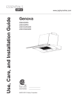
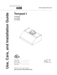
Genova
ZGE-E30AS
ZGE-E36AS
ZGE-E30AS290
ZGE-E36AS290
Model number:
Serial Number:
APR14.0401 © Zephyr Corporation
www.zephyronline.com
INSTALLATION
Ducting Calculation Sheet .......................................
Mounting Height & Clearance................................
Ducting Options ...........................................................
+RRG6SHFL¿FDWLRQV ...................................................
Preparing the Cabinet ...............................................
Installing the Hood ......................................................
Ductless Recirculation ..............................................
5
6
7
8
9
10 - 12
13
FEATURES & CONTROLS
Touch Controls .............................................................. 14-15
Remote Control (Optional)....................................... 16
MAINTENANCE
Hood and Filter Cleaning ......................................... 17
Lights ................................................................................ 18
Wiring Diagram ............................................................ 19
TROUBLESHOOTING................................................................ 20
LIST OF PARTS AND ACCESSORIES .............................. 21
1
Table of Contents
SAFETY NOTICE ................................................................. 2-3
LIST OF MATERIALS....................................................... 4
www.zephyronline.com
Important Safety Notice
READ AND SAVE THESE INSTRUCTIONS
WARNING
TO REDUCE THE RISK OF FIRE OR ELECTRIC SHOCK, DO NOT USE THIS FAN WITH ANY SOLID-STATE CONTROL DEVICE.
WARNING
TO REDUCE THE RISK OF FIRE ELECTRIC SHOCK, OR INJURY TO PERSONS, OBSERVE THE FOLLOWING:
a. Use this unit only in the manner intended by the manufacturer, if you have questions, contact the manufacturer.
b. Before servicing or cleaning unit, switch power off at service panel and lock panel to prevent power from being switched on accidentally.
When the service disconnecting means cannot be locked, securely fasten a prominent warning device, such as a tag, to the service
panel.
CAUTION
For general ventilating use only. Do not use to exhaust hazardous or explosive materials and vapors. Take care when using cleaning
agents or detergents. Suitable for use in household cooking area.
WARNING
TO REDUCE THE RISK OF RANGE TOP GREASE FIRE:
a. Never leave surface units unattended at high settings. Boilovers cause smoking and greasy spillovers that may ignite. Heat oils slowly
on low or medium settings.
E $OZD\VWXUQKRRG21ZKHQFRRNLQJDWKLJKKHDWRUZKHQÀDPLQJIRRG
F &OHDQYHQWLODWLQJIDQVIUHTXHQWO\*UHDVHVKRXOGQRWEHDOORZHGWRDFFXPXODWHRQIDQRU¿OWHU
d. Use proper pan size. Always use cookware appropriate for the size of the surface element.
H .HHSIDQ¿OWHUVDQGJUHDVHODGHQVXUIDFHVFOHDQ
f. Use high setting on hood only when necessary.
g. Don’t leave hood unattended when cooking.
h. Always use cookware and utensils appropriate for the type of and amount of food being prepared.
WARNING
TO REDUCE THE RISK OF INJURY TO PERSONS IN THE EVENT OF A RANGE TOP FIRE, OBSERVE THE FOLLOWING:
D 6027+(5)/$0(6ZLWKDFORVH¿WWLQJOLGFRRNLHVKHHWRUPHWDOWUD\WKHQWXUQRIIWKHEXUQHU%(&$5()8/7235(9(17%8516
,IWKHÀDPHVGRQRWJRRXWLPPHGLDWHO\(9$&8$7($1'&$//7+(),5('(3$570(17
b. NEVER PICK UP A FLAMING PAN – You may be burned.
c. DO NOT USE WATER, including wet dishcloths or towels – a violent steam explosion will result.
d. Use an extinguisher ONLY if:
1. You know you have a Class ABC extinguisher, and you already know how to operate it.
7KH¿UHLVVPDOODQGFRQWDLQHGLQWKHDUHDZKHUHLWVWDUWHG
7KH¿UHGHSDUWPHQWLVEHLQJFDOOHG
<RXFDQ¿JKWWKH¿UHZLWK\RXUEDFNWRDQH[LW
WARNING
TO REDUCE THE RISK OF FIRE, ELECTRIC SHOCK OR INJURY TO PERSONS, OBSERVE THE FOLLOWING:
D ,QVWDOODWLRQZRUNDQGHOHFWULFDOZLULQJPXVWEHGRQHE\TXDOL¿HGSHUVRQVLQDFFRUGDQFHZLWKDOODSSOLFDEOHFRGHVDQGVWDQGDUGV
,QFOXGLQJ¿UHUDWHGFRQVWUXFWLRQ
E 6XI¿FLHQWDLULVQHHGHGIRUSRZHUFRPEXVWLRQDQGH[KDXVWLQJRIJDVHVWKURXJKWKHÀXHFKLPQH\RIIXHOEXUQLQJHTXLSPHQWWRSUHYHQW
back-drafting. Follow the heating equipment manufacturer’s guideline and safety standards such as those published by the National
Fire Protection Association (NFPA) and the American Society for Heating, Refrigeration and Air Conditioning Engineers (ASHRAE) and
the local code authorities.
c. When cutting or drilling into wall or ceiling, do not damage electrical wiring and other hidden utilities.
d. Ducted fans must always vent to the outdoors.
e. NEVER place a switch where it can be reached from a tub or shower.
f. Make sure the power is off before installing, wiring or maintenancing.
2
TO REDUCE THE RISK OF FIRE, USE ONLY METAL DUCTWORK.
CAUTION
7RUHGXFHULVNRI¿UHDQGWRSURSHUO\H[KDXVWDLURXWVLGH'RQRWYHQWH[KDXVWDLULQWRVSDFHVZLWKLQZDOOVFHLOLQJV
attics, crawl spaces or garages. Hood not intended for installation over an outdoor grill.
OPERATION
$OZD\VOHDYHVDIHW\JULOOHVDQG¿OWHUVLQSODFH:LWKRXWWKHVHFRPSRQHQWVRSHUDWLQJEORZHUVFRXOGFDWFKRQWRKDLU¿QJHUV
and loose clothing.
The manufacturer declines all responsibility in the event of failure to observe the instructions given here for installation,
maintenance and suitable use of the product. The manufacturer further declines all responsibility for injury due to
negligence and the warranty of the unit automatically expires due to improper maintenance.
*NOTE: Please check www.zephyronline.com for revisions before doing any custom work.
ELECTRICAL REQUIREMENTS
Important:
Observe all governing codes and ordinances.
It is the customer’s responsibility:
7RFRQWDFWDTXDOL¿HGHOHFWULFDOLQVWDOOHU
- To assure that the electrical installation is adequate and in conformance with National Electrical Code, ANSI/NFPA 70
latest edition* or CSA standards C22.1-94, Canadian Electrical Code, Part 1 and C22.2 No.0-M91 - latest edition** and
all local codes and ordinances.
,IFRGHVSHUPLWDQGDVHSDUDWHJURXQGZLUHLVXVHGLWLVUHFRPPHQGHGWKDWDTXDOL¿HGHOHFWULFLDQGHWHUPLQHWKDWWKH
ground path is adequate.
Do not ground to a gas pipe.
&KHFNZLWKDTXDOL¿HGHOHFWULFLDQLI\RXDUHQRWVXUHWKHUDQJHKRRGLVSURSHUO\JURXQGHG
Do not have a fuse in the neutral or ground circuit.
*National Fire Protection Association Batterymarch Park, Quincy, Massachusetts 02269
** CSA International 8501 East Pleasant Valley Road, Cleveland, Ohio 44131-5575
This appliance requires a 120V 60Hz electrical supply and connected to an individual properly grounded branch circuit
protected by a 15 or 20 ampere circuit breaker or time delay fuse. Wiring must be 2 wire with ground. Please also refer to
Electrical Diagram on product.
A cable locking connector (not supplied) might also be required by local codes. Check with local requirements, purchase
and install appropriate connector if necessary.
ZGE-E30AS, ZGE-E36AS - 370 Watts, 3.5 Amps
ZGE-E30AS290, ZGE-E36AS290 - 167 Watts, 3.5 Amps
3
Important Safety Notice
WARNING
List of Materials
www.zephyronline.com
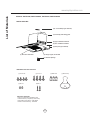
MODELS: ZGE-E30AS, ZGE-E30AS290, ZGE-E36AS, ZGE-E36AS290
PARTS SUPPLIED
(1) 6” round damper (pre-installed)
(1) hood body with sliding glass
(2) upper installation brackets
(2) lower installation brackets
(1) filler panel (pre-installed)
(2) halogen lights, GU-10 50W
(1) decorative mesh filter
(1) hardware package
HARDWARE PACKAGE CONTENTS
(4) 3/16 x 3/8”
(4) 3/16 x 1”
(2) M4 x 8
(2) M4 x 1”
(3) Wire Nuts
PARTS NOT SUPPLIED
- Ducting, conduit and all installation tools
- Cable connector (if required by local codes)
- Recirculating kit accessory - ZRC-00GE
- Remote control accessory - 14000005
4
(1) Suction Cup
Equivalent number
length x used
=
Duct pieces
Total
Total
3-1/ 4” x 10” 1 Ft.
Rect.,
straight
x(
) =
Ft.
6”- 8” Round 30 Ft.
wall cap
with damper
x(
) =
Ft.
7” Round,
straight
1 Ft.
x(
) =
Ft.
6”- 8” Round, 30 Ft.
roof cap
x(
) =
Ft.
8” Round,
straight
1 Ft.
x(
) =
Ft.
6” round to
1 Ft.
3-1/ 4” x 10”
rect.
transition
x(
) =
Ft.
3-1/ 4” x 10” 15 Ft.
Rect. 90 0
elbow
x(
) =
Ft.
x(
) =
Ft.
3-1/ 4” x 10” 9 Ft.
Rect. 45 0
elbow
x(
) =
Ft.
6” round to
16 Ft.
3-1/ 4” x 10”
rect.
transition
90 0 elbow
7” or 8”
Round,
90 0 elbow
15 Ft.
x(
) =
Ft.
3-1/ 4” x 10” 24 Ft.
Rect. 90 0
flat elbow
x(
7” or 8”
Round,
45 0 elbow
9 Ft.
x(
) =
Ft.
3-1/ 4” x 10” 30 Ft.
Rect.
wall cap
with damper
x(
7” or 8”
30 Ft.
Round
wall cap
with damper
x(
) =
Ft.
3-1/ 4” x 10” 5 Ft.
Rect. to
6” round
transition
x(
) =
Ft.
7” or 8”
Round,
roof cap
x(
) =
Ft.
3-1/ 4” x 10” 20 Ft.
Rect. to
6” round
transition
90 0 elbow
x(
) =
Ft.
7” round to
8 Ft.
3 1/ 4” x 10”
rect.
transition
x(
) =
Ft.
) =
Ft.
15 Ft.
x(
) =
Ft.
7” round to
23 Ft.
3-1/ 4” x 10”
rect.
transition
90 0 elbow
x(
6” Round,
90 0 elbow
6” Round,
45 0 elbow
9 Ft.
x(
) =
Ft.
Subtotal column 2 =
Ft.
Subtotal column 1 =
Ft.
Total ductwork
Ft.
) =
) =
Subtotal column 1 =
Ft.
Ft.
Ft.
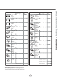
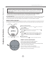
Maximum Duct Length: For satisfactory air movement,
the total duct length of a 3 1/ 4” x 10” rectangular 6” or 7”
diameter round duct should not exceed 100 equivalent feet.
5
30 Ft.
=
Installation – Ducting Calculation Sheet
Equivalent number
length x used
=
Duct pieces
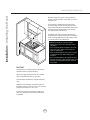
Installation – Installing the Hood
www.zephyronline.com
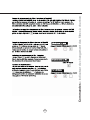
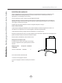
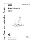
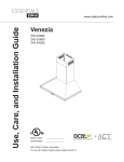
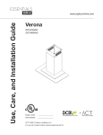
Mounting height from top of cooking surface to
bottom of hood should be no less than 24” and no
more than 32”.
It is important to install the hood at the proper
mounting height. Hoods mounted too low could
UHVXOWLQKHDWGDPDJHDQG¿UHKD]DUGZKLOHKRRGV
mounted too high will be hard to reach and will
ORVHSHUIRUPDQFHDQGHI¿FLHQF\
If available, also refer to range manufacturer’s
height clearance requirements and recommended
hood mounting height above range. Always check
your local codes for any differences.
in.
” m x.
4
2 ma
”
32
DAMAGE-SHIPMENT / INSTALLATION:
3OHDVHIXOO\LQVSHFWXQLWIRUGDPDJHEHIRUH
installation.
,IWKHXQLWLVGDPDJHGLQVKLSPHQWUHWXUQWKH
unit to the store in which it was bought for
repair or replacement.
,IWKHXQLWLVGDPDJHGE\WKHFXVWRPHUUHSDLU
or replacement is the responsibility of the
customer.
,IWKHXQLWLVGDPDJHGE\WKHLQVWDOOHULIRWKHU
than the customer), repair of replacement must
be made by arrangement between customer
and installer.
36”
DUCTING
A minimum of 6” round ducting must be used to
PDLQWDLQPD[LPXPDLUÀRZHI¿FLHQF\
Always use rigid type metal ducts only. Flexible
GXFWVFRXOGUHVWULFWDLUÀRZE\XSWR
Use calculation worksheet to compute total duct
work.
ALWAYS, when possible, reduce the number of
transitions and turns. If a long duct run is required,
increase duct size from 6” to 7” or 8”.
If turns or transitions are required: Install as far
away from opening and as far apart, between 2,
as possible.
6
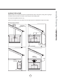
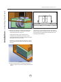
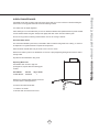
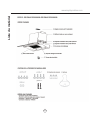
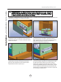
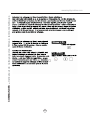
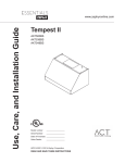
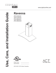
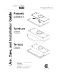
NEVER exhaust air or terminate duct work into spaces between walls, crawl spaces, ceiling, attics or garages.
All exhaust must be ducted to the outside, unless using the recirculating option.
Use single wall rigid Metal ductwork only.
)DVWHQDOOFRQQHFWLRQVZLWKVKHHWPHWDOVFUHZVDQGWDSHDOOMRLQWVZFHUWL¿HG6LOYHU7DSHRU'XFW7DSH
Ducting Options Example
roof pitch w/
flashing & cap
side wall cap
w/ gravity damper
soffit or crawl space
ductless
recirculating
ductless
recirculating
7
soffit
Installation – Ducting Options
WARNING FIRE HAZARD
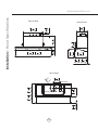
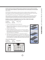
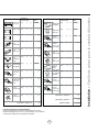
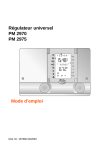
front of hood
side of hood
1
9 2 "
242mm
3"
76mm
15
29 16 "
760mm
1 1"
8
28mm
11"
280mm
1 5"
8
41mm
11
19 16 "
500mm
7
35 8 "
912mm
1
11 4 "
286mm
6"
153mm
3
1
to 1 "
4 "
8
6mm
35mm
top of hood
junction box
5
8 "
16mm
blower outlet
1
7 16 "
180mm
3
7 4 "
197mm
m
3m
15
6"
1
5
17 2 " to 18 8 "
445mm
473mm
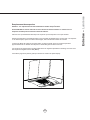
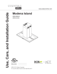
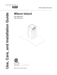
Installation – +RRG6SHFL¿FDWLRQV
www.zephyronline.com
8
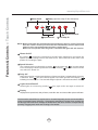
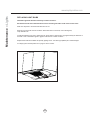
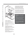
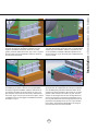
Installation – Preparing the Cabinet
7”
7 3/4”
19-7/8”
98”
7/
1-
9/
16
”
C/L
Fig.1
front edge
glass handle
Fig.2
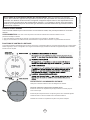
1. Determine and mark center line on wall and cabinet bottom with a pencil.
2. If the cabinet bottom is recessed, wood blocking must be installed to ensure proper
DOLJQPHQWRIWKHKRRGZLWKWKHFDELQHWERWWRP:RRGEORFNLQJVKRXOGEHÀXVK
within cabinet bottom.
3. Follow the dimensions in Fig.1 and cut-out the bottom of your cabinet to create an opening
IRUWKHKRRGWR¿WWKURXJK,I\RXKDYHDIUDPHOHVVFDELQHWEHJLQWKH´PHDVXUHPHQW
(referenced in Fig.1) from front of the cabinet door. This way the front edge of the hood will
EHÀXVKZLWKWKHFDELQHWGRRUVZKHQFORVHGVHH)LJ
9
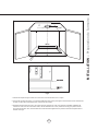
Installation – Installing the Hood
www.zephyronline.com
! WARNING: Electrical wiring must be done by a qualified person(s) in
accordance with all applicable codes and standards. This range hood must be
properly grounded. Turn off electrical power at service entrance before wiring.
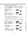
1) Prepare electrical wiring and ducting in cabinet. Location of junction box and blower outlet can be found on page 8.
Fig.3
Fig.4
2) Unscrew the (10) screws from front panel and place
the panel aside, Fig.3. You will now have access to the
interrior of the range hood.
3) Open cabinet doors. Lift range hood and slide it through
the opening located in the bottom of the cabinet, Fig.4.
Make sure opening matches the dimensions on page 9,
Fig.1.
2
1
Fig.5
Fig.6
4) There are spring clips located on the left and right sides
of the hood body which will temporarily hold the hood in
place, Fig.5.
5) Secure upper brackets to left and right sides of hood
body by using (2) 3/16 x 3/8” screws for each bracket.
Fig.6. Make sure the (2) captive nut screw holes on
the bracket are facing downward. Note: Due to limited
workspace in 30” cabinets you will need to use a right
angle or 2” long Philips head screwdriver.
10
Fig.7
Fig.8
6) Place lower installation brackets under upper installation
brackets located on left and right sides of hood body,
Fig.7. Note: The wider portion of the lower installation
bracket should be at the bottom.
7) From inside the hood, secure (1) M4x8 screw into
each lower installation bracket. The position of this
screw is adjustable to accomodate various cabinet
bottom thicknesses, Fig.8. Do not fully tighten screw yet.
2
1
A
B
Fig.9
8) Install (2) 3/16x1” screws into the captive nuts of each
upper installation bracket. Tighten screws to adjust the
height of range hood until there is no gap between the
cabinet bottom and front edge of hood, Fig.9. After hood
is positioned, fully tighten the lower installation bracket
screw from step 7, Fig.8-1.
Fig.10
$¿OOHUSDQHOLVLQFOXGHGWRDFFRPRGDWHPXOWLSOHFDELQHW
depths. Inside the hood are (2) thumb screws located
on the left and right sides at the back of the hood,
Fig.10A. Turn each thumb screw clockwise to push
WKH¿OOHUSDQHOWRZDUGVWKHZDOO)LJ%7LJKWHQWKXPE
VFUHZVXQWLO¿OOHUSDQHOPHHWVWKHZDOODQGLVVHFXUHGLQ
SODFH6HHKRRGVSHFL¿FDWLRQVRQSDJHIRUVXSSRUWHG
cabinet depths.
11
Installation – Installing the Hood
1
Installation – Installing the Hood
www.zephyronline.com
A
Fig.11
Fig.12A
10) Place 6” round ducting over blower collar and secure
with aluminum duct tape. If using hood in ductless
recirculating mode turn to page 13.
Install electrical wiring. Note: A cable lock (not
included) may be required by local codes. Check
with local requirements and codes, purchase and install
appropriate connector if necessary.
Make sure no packing material is inside hood. Power
up hood check for leaks around duct tape and verify all
functions.
Fig.12B
12) Place front panel back on hood body and secure in
place by using the (10) screws previously removed from
step 2.
12
11) Secure (2) 1” wood screws (A) into the screw holes on
WKHOHIWDQGULJKWVLGHVRIWKH¿OWHURSHQLQJ7KLVZLOOVHFXUH
the hood body to the cabinet base and prevent the hood
from shifting after installation.
We recommend to ALWAYS exhaust air outside of the home by employing existing or installing new duct
ZRUNLISRVVLEOH7KHKRRGLVPRVWHIIHFWLYHDQGHI¿FLHQWDVDQH[KDXVWKRRG2QO\ZKHQWKHH[KDXVWRSWLRQ
is not possible should you recourse to converting the hood into a recirculating hood.
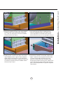
:KHQFRQYHUWHGWREHDUHFLUFXODWLQJKRRGDFKDUFRDO¿OWHULVUHTXLUHGRQWRSRIWKHGHFRUDWLYHPHVK¿OWHU
2UGHUDFFRUGLQJWRLWVSDUWQXPEHUEHORZ7KHGHFRUDWLYHPHVK¿OWHULVLQWHQGHGWRFDSWXUHUHVLGXHIURP
FRRNLQJDQGWKHRSWLRQDOFKDUFRDO¿OWHUKHOSVWRSXULI\IXPHVH[KDXVWHGIURPFRRNLQJIRUUHFLUFXODWLRQ
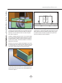
RECIRCULATING KIT (REQUIRED IF NOT DUCTED OUTSIDE THE HOME)
.LWLQFOXGHVFKDUFRDO¿OWHUEUDFNHWVDQGUHWXUQDLUYHQW
Hood Model
ZGE (all models)
Part No.
ZRC-00GE
Filters in Pkg.
1
1. Purchase recirculating kit per the part number above.
5HPRYHGHFRUDWLYHPHVK¿OWHUIURPKRRGDQGSODFHFKDUFRDO¿OWHURQWRSRI
PHVK¿OWHU6HFXUHFKDUFRDO¿OWHUWRPHVK¿OWHUE\XVLQJWKHVXSSOLHGZLUH
brackets as shown in Fig.13.
5HLQVWDOOGHFRUDWLYHPHVK¿OWHU
4. In order to recirculate the air properly, a return air vent must be installed to
allow recycled air to be returned to the kitchen, Fig. 14. Ducting must be run
from the blower to the return air vent. The return air vent can be positioned
RQWRSRIWKHFDELQHWRULQDVRI¿WFHLOLQJ
5. Enable Charcoal Filter Change indicator on control panel. See page 15.
&KDUFRDO¿OWHUPXVWEHUHSODFHGDIWHUHYHU\KRXUVRIXVHRUDSSUR[LPDWHO\
every 3 to 4 months based on an average daily use of 1 hour of cooking time)
The microprocessor in the controls, when set, will elapse and count usage
WLPHDQGLQGLFDWHZKHQFKDUFRDO¿OWHUUHSODFHPHQWLVUHTXLUHGHYHU\KUV
Charcoal Filter Replacement
Hood Model
ZGE (all models
Part No.
Z0F-C0GE
Qty to Order
1
Fig.13
Fig.14
13
Installation – Ductless Recirculation
Ductless recirculation is intended for applications where an exhaust duct work is not possible to be installed.
When converted, the hood functions as a recirculating hood rather than an exhaust hood. Fumes and exhaust
IURPFRRNLQJDUHGUDZQDQG¿OWHUHGE\DQRSWLRQDOFKDUFRDO¿OWHU7KHDLULVWKHQSXUL¿HGDQGUHFLUFXODWHGEDFN
within the home.
Features & Controls – Touch Controls
www.zephyronline.com
Blower On/Off
Display (speed level, delay off, filter clean/replace)
Lights Normal/Dim/Off
Speed Selection
5 Min Delay Off
NOTE: Blower and lights will automatically shut off when the glass is closed. The hood
also has a built in memory function that will automatically turn the blower and
lights on at the last setting when the glass is pulled open.
Blower will not operate while the glass is closed but the lights will still function.
1 Blower On/Off
By pressing
, the blower is switched On and Off. When switched On, the blower will
operate at the last setting before it was switched Off. When switched Off the entire hood
powers Off, including the lights.
2 Speed Selection
The 3 speed levels are selected by pressing
to decrease and
to increase speed
level. The display indicates speed level selected. Pressing
when the hood is Off will
also switch the blower On.
3 Delay Off
Delay Off is used for programmed shut down of blower and lights 5 minutes after the function
is activated. Press
once and a dot will appear in the lower right side of the Display
indicating the function is on. The hood will change to Speed 1 and shut down after 5 minutes.
4 Lights Normal/Dim/Off
Switch lights on to Normal by pressing
once, again to Dim and again to switch Off.
5 Display
Displays blower speed level, delay off status, mesh filter clean and charcoal filter replace notification.
The decorative mesh filter is required to be cleaned frequently and as recommended in
order to maintain blower efficiency. If improperly maintained, residue from cooking will
sift through filter and cause damage to hood blower and other sensitive components by
possibly clogging duct work and creating a fire hazard.
14
Whether your hood is installed as an exhaust or purifying unit, a decorative mesh filter is fitted by the factory. This
mesh filter is intended to filter out residue from cooking. It need not be replaced on a regular basis but is required to
be kept clean. After every 30 hours of use the Filter Clean Reminder function in the microprocessor will automatically remind you by a flashing F when the mesh filter needs to be cleaned. The filter can be cleaned by hand
with non-abrasive soap or in a dishwasher. A heavily soiled filter should also be soaked in grease cutting
detergent prior to cleaning.
Decorative Mesh Filter Clean Indicator
When F flashes on display, the mesh filter installed is
required to be cleaned. This will occur after every 30
hours of use.
Re-setting Function
Reset the filter clean reminder timer when filter is cleaned
and re-installed. With hood off, press and hold
for
approximately 5 seconds until F on display disappears
.
. The filter clean reminder function is now reset
and a new 30 hours elapse cycle is initiated.
Clean Filters
display < F > flashes
F
To Reset
hold 5 sec.
display from < F > to < >
F
Charcoal Filter Replace Reminder (charcoal filter, if installed)
When your hood is installed as a recirculating unit it must be fitted with a charcoal filter to purify exhaust and fumes
from cooking and then recirculate the air within the home. This charcoal filter must be replaced after every 120 hours
of use. The charcoal filter should never be cleaned or placed in a dish washer.
The charcoal filter replace reminder function in the microprocessor needs to be switched on. When switched on, the
microprocessor will elapse and count usage time. When charcoal filter replacement is needed a flashing C will
appear on the display.
Setting the Charcoal Filter Replace Reminder
Set Mode
With hood off, hold
for approximately 5 seconds.
The display will change from
(exhaust mode) to
C (recirculating mode). This indicates that the elapse
timer function is switched on and charcoal filter is being
used.
hold 5 sec.
display from < - > to < C >
C
Charcoal Filter Replace Indicator
When the display C starts flashing, the charcoal filter
needs to be replaced. Purchase replacement charcoal
filters from Zephyr.
Re-setting Function
After charcoal filter is replaced, with hood off, press and
hold
for apprimately 5 seconds until C on the
display disappears
. The filter change reminder is
now re-set and a new 120 hour elapse cycle is initiated.
15
Set Mode
Change
FIlter
display < C > flashes
C
To Reset
hold 5 sec.
display from < C > to < >
C
Features & Controls – Filter Clean and Replace Reminder
Decorative Mesh Filter Clean Reminder (metal mesh filter)
Features & Controls – Remote Control (Optional)
www.zephyronline.com
FCC Caution:7RDVVXUHFRQWLQXHGFRPSOLDQFHDQ\FKDQJHVRUPRGL¿FDWLRQVQRWH[SUHVVO\DSSURYHGE\WKHSDUW\
responsible for compliance could void the user’s authority to operate this equipment. This device complies with Part
15 of the FCC Rules. Operation is subject to the following two conditions. (1) This device may not cause harmful
interference, and (2) This device must accept any interference received, including interference that may cause
undesired operation.
Remote control is sold as an optional accessory. Purchase Zephyr part number: 14000005
This remote control may operate in humid environments, but not when placed on a wet surface.
SYNCHRONIZATION: To create a unique link between your range hood and remote control please follow the below steps:
1. With range hood off, press and hold the “lights” button on the range hood until the letter “F” shows on the display screen.
2. Press the “lights” button on the remote, the lights on the hood will turn on. The synchronization is complete.
REMOTE CONTROL FEATURES:
The RF remote control is equipped with a magnet for easy storage. The remote may be placed on any magnetic surface such
as a refrigerator or the Zephyr remote holder. Maximum remote control communication distance from power pack is 15 feet.
Blower On/
Speed Selection 1
Blower On/
2 Power Off
1 Blower On/Speed Selection
By pressing
, the blower is switched On. Press
three blower speeds.
again to cycle through all
2 Blowers On/Hood Off
By pressing
, the blowers will power on at the last speed setting. Press
again and the entire hood will power off, including lights.
3 Delay Off
By pressing
, the blower and lights will enter Delay Off mode. A dot will
appear in the lower right corner of the power pack display
indicating the
function is on. The blower will change to speed 1 and shut down after 5
minutes.
4 Lights On/Dim/Off
5 Min Delay Off 3
4 Lights On/Dim/Off
Switch lights On by pressing
once, again to dim and again to switch Off.
REMOTE CONTROL MAINTENANCE:
Clean the remote control using non abrasive detergents
Follow instructions below for replacing battery.
8VLQJDVPDOOÀDWKHDGVFUHZGULYHUUDLVHWKHFRYHURIWKHEDWWHU\GRRUA)
in order to access the battery compartment.
+
A
-
Remove the battery and replace with Type A23 12V.
Negative end of battery should face the spring inside the remote.
Replace battery door and recycle old battery.
16
Periodically clean with hot soapy water and clean cotton cloth. Do not use corrosive or abrasive detergent
steel wool or scouring pads which will scratch and damage surface.
For heavier soil use liquid degreaser.
After cleaning it is recommended that you use non-abrasive stainless steel polish/cleaners to polish and buff
out the stainless luster and grain. Always scrub lightly with clean cotton cloth and with the grain.
Do not use any product containing chlorine bleach. Do not use “orange” cleaners.
Decorative Mesh Filters
7KHPHVK¿OWHULQVWDOOHGE\WKHIDFWRU\LVLQWHQGHGWR¿OWHURXWUHVLGXHDQGJUHDVHIURPFRRNLQJ,WQHHGQRW
be replaced on a regular basis but is required to be kept clean.
Filter should be cleaned after every 30 hours of use or once a month.
Remove and clean by hand or in dishwasher on low heat. Spray degreasing detergent and leave to soak if
heavily soiled.
'U\¿OWHUDQGUHLQVWDOOEHIRUHXVLQJKRRG
Replacing Mesh Filter
6KRXOG¿OWHUZHDURXWGXHWRDJHDQG
prolonged use, replace with the following part
number:
Hood Model:
All ZGE Models
Part No.
50200036
Qty. to Order.
1
5HSODFHDQ\GDPDJHG¿OWHUWKDWKDVSXQFWXUHG
or broken mesh or damaged frame.
7RUHPRYHGHFRUDWLYHPHVK¿OWHU
1
1. Pull down on handle.
7LOW¿OWHUGRZQDQGUHPRYHIURPKRRG
2
17
Maintenance – Hood and Filter Cleaning
SURFACE MAINTENANCE:
Maintenance – Lights
www.zephyronline.com
REPLACING LIGHT BULBS
CAUTION: Light bulb becomes extremely hot when turned on.
DO NOT touch bulb until switched off and cooled. Touching hot bulbs could cause serious burns.
Make sure all power is turned off and bulbs are not hot.
Remove by turning bulb counter-clockwise. Note: Bulb does not unscrew; it turns 60 degrees,
stops and falls out.
,IEXOEVDUHGLI¿FXOWWRWXUQGXHWRSURORQJHGXVH¿UPO\DWWDFKDJODVVVXFWLRQFXSDSSUR[LPDWHO\WKHGLDPHWHURI
the bulb or use a rubber/latex glove to grip the bulb and turn counter clockwise.
Replacement bulbs are available at specialty lighting stores. Purchase type (MR16) GU-10 50W halogen.
For Zephyr part numbers please turn to page 21 of the manual.
18
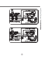
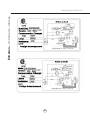
Maintenance – Wiring Diagram
3.5A
3.5A
370W
270W
19
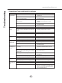
Troubleshooting
www.zephyronline.com
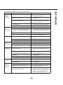
TROUBLESHOOTING PROCEDURES FOR GENOVA
Issue
Cause
What to do
After installation,
the unit doesn’t
work.
1. The power source is not turned ON.
1. Make sure the circuit breaker and the unit’s
power is ON.
2. The power line and the cable locking connector
is not connecting properly.
2. Check the power connection with the unit is
connected properly.
3. The switch board and control board wirings are
disconnected.
3. Make sure the wirings between the switch
board and control board are connected
properly.
4. The wires on control board are loose.
4. Make sure the wires on the control board are
connected properly.
5. The switch board or control board is defective.
5. Change the switch board or control board.
1. The blower is defective, possible seized.
1. Change the blower.
2. The thermally protected system detects if the
motor is too hot to operate and shuts the motor
down.
2. The motor will function properly after the
thermally protected system cool down.
Light works,
but motor is not
turning.
3. Damaged capacitor.
3. Change the capacitor.
4. The blower wire is not connected.
4. Make sure the blower wire is plugged into the
molex connector.
1. The blower is not secure in place.
1. Tighten the blower screws in place.
2. Damaged blower wheel.
2. Change the blower.
3. The hood is not secured in place.
3. Check the installation of the hood.
1. Defective halogen bulb.
1. Change the halogen bulb.
2. The light bulb is loose.
2. Tighten the light bulb.
3. The wires on the control board are loose.
3. Make sure the wires on control board are
connected properly.
1. The hood might be hanging too high from the
cook top.
1. Adjust the distance between the cook top and
the bottom of the hood within 24” and 32”
range.
2. Wind from opened windows or opened doors in
the surrounding area is affecting the ventilation
of the hood.
2. Close all the windows and doors to eliminate
WKHRXWVLGHZLQGÀRZ
3. Blockage in the duct opening or duct work.
3. Remove all the blocking from the duct work or
duct opening.
4. The direction of duct opening is against the wind.
4. Adjust the duct opening direction.
5. Using the wrong size of ducting.
5. Change the ducting to correct size.
0HWDO¿OWHULV
vibrating.
0HVK¿OWHULVORRVH
&KDQJHWKHPHVK¿OWHU
2. Handle spring clip does not work properly
2. Adjust the handle until the spring clip works
RF Remote
control does not
work
1. Battery is dead
1. Replace battery with type A23 12v
2. Poor communication with the hood
2. Remote control must be within 15 ft of hood
3. RF remote lost communication with hood
3. Reset hood and remote by switching power
off at the circuit breaker for 5 minutes. Place
remote on counter top near hood and switch
the circuit breaker back on.
The unit is
vibrating.
The motor is
working, but the
lights are not.
The hood is
not venting out
properly.
20
PART#
Replacement Parts
Light Bulb GU10 50W (each)
Decorative Mesh Filter
Z0B0020
50200036
Optional Accessories
Recirculating Kit
Replacement Charcoal Filter (each)
RF Remote Control
ZRC-00GE
Z0F-C0GE
14000005
To order parts, visit us online at http://store.zephyronline.com or call us at 1.888.880.8368
21
List of Parts and Accessories
DESCRIPTION
STAPLE YOUR RECEIPT HERE
Proof of the original purchase
date is needed to obtain
service under warranty
Limited Warranty
TO OBTAIN SERVICE UNDER WARRANTY OR FOR ANY SERVICE RELATED QUESTIONS, please call:
1-888-880-8368
Zephyr Corporation (referred to herein as “we” or “us”) warrants to the original consumer purchaser (referred to herein
as “you” or “your”) of Zephyr products (the “Products”) that such Products will be free from defects in materials or workmanship as follows:
Three Year Limited Warranty for Parts: For three years from the date of your original purchase of the Products, we
will provide, free of charge, Products or parts (including LED light bulbs, if applicable) to replace those that failed due to
manufacturing defects. We may choose, in our sole discretion, to repair or replace parts before we elect to replace the
Products.
One Year Limited Warranty for Labor: For one year from the date of your original purchase of the Products, we will
provide, free of charge, the labor cost associated with repairing the Products or parts to replace those that failed due to
manufacturing defects. After the first year from the date of your original purchase, you are responsible for all labor costs
associated with this warranty.
Warranty Exclusions: This warranty covers only repair or replacement, at our option, of defective Products or parts
and does not cover any other costs related to the Products including but not limited to: (a) normal maintenance and
service required for the Products and consumable parts such as incandescent or halogen light bulbs, metal and carbon
filters and fuses; (b) any Products or parts which have been subject to freight damage, misuse, negligence, accident,
faulty installation or installation contrary to recommended installation instructions, improper maintenance or repair (other
than by us); (c) commercial use of the Products or use otherwise inconsistent with its intended purpose; (d) natural wear
of the finish of the Products or wear caused by improper maintenance, use of corrosive and abrasive cleaning products,
pads, and oven cleaner products; (e) chips, dents or cracks caused by abuse or misuse of the Products; (f) service trips
to your home to teach you how to use the Products; or (g) damage to the Products caused by accident, fire, floods or act
of God. If you are outside our service area, additional charges may apply for shipping costs for warranty repair at our
designated service locations and for the travel cost to have a service technician come to your home to repair, remove or
reinstall the Products. After the first year from the date of your original purchase, you are also responsible for all labor
costs associated with this warranty.
Limitations of Warranty. OUR OBLIGATION TO REPAIR OR REPLACE, AT OUR OPTION, SHALL BE YOUR SOLE
AND EXCLUSIVE REMEDY UNDER THIS WARRANTY. WE SHALL NOT BE LIABLE FOR INCIDENTAL, CONSEQUENTIAL OR SPECIAL DAMAGES ARISING OUT OF OR IN CONNECTION WITH THE USE OR PERFORMANCE OF
THE PRODUCTS. THE EXPRESS WARRANTIES IN THE PRECEDING SECTION ARE EXCLUSIVE AND IN LIEU OF
ALL OTHER EXPRESS WARRANTIES. WE HEREBY DISCLAIM AND EXCLUDE ALL OTHER EXPRESS WARRANTIES FOR THE PRODUCTS, AND DISCLAIM AND EXCLUDE ALL WARRANTIES IMPLIED BY LAW, INCLUDING
THOSE OF MERCHANTABILITY AND FITNESS FOR A PARTICULAR PURPOSE. Some states or provinces do not
allow limitations on the duration of an implied warranty or the exclusion or limitation of incidental or consequential damages, so the above limitations or exclusions may not apply to you. To the extent that applicable law prohibits the exclusion of implied warranties, the duration of any applicable implied warranty is limited to the same two-year period
described above. Any oral or written description of the Products is for the sole purpose of identifying the Products and
shall not be construed as an express warranty. Prior to using, implementing or permitting use of the Products, you shall
determine the suitability of the Products for the intended use, and you shall assume all risk and liability whatsoever in
connection with such determination. We reserve the right to use functionally equivalent refurbished or reconditioned
parts or Products as warranty replacements or as part of warranty service. This warranty is not transferable from the
original purchaser and applies in the United States and Canada.
To Obtain Service Under Limited Warranty: To qualify for warranty service, you must: (a) notify us at the address or
telephone number stated below within 60 days of the discovery of the defect; (b) give the model number and part identification number and serial number; and (c) describe the nature of any defect in the Product or part. At the time of the
request for warranty service, you must present evidence of your proof of purchase and proof of the original purchase
date. If we determine that the warranty exclusions listed above apply or if you fail to provide the necessary documentation to obtain service, you will be responsible for all shipping, travel, labor and other costs related to the services.
Please check our website for any revisions, www.zephyronline.com.
MAY13.0301
Guide d’utilisation, d’entretien et d’installation
www.zephyronline.com
Genova
ZGE-E30AS
ZGE-E36AS
ZGE-E30AS290
ZGE-E36AS290
Numéro de modèle :
Numéro de série :
APR14.0401 © Zephyr Corporation
www.zephyronline.com
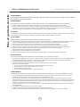
INSTALLATION
Feuille de calcul pour le conduit ...........................
Espace libre et hauteur de montage ...................
Options d’installation pour le conduit ..................
6SpFL¿FDWLRQVGHODKRWWH.........................................
Préparation de l’armoire...........................................
Installation de la hotte....................................
Reprise d’air sans conduit .......................................
5
6
7
8
9
10-12
13
COMMANDES
&RPPDQGHVjHIÀHXUHPHQW.................................. 14-16
Commande à distance (optionnel) .................. 17
ENTRETIEN
1HWWR\DJHGHV¿OWUHVHWGHODKRWWH ...................... 18
Ampoules ....................................................................... 19
Schéma de câblage....................................... 20
DÉPANNAGE ................................................................................. 21
LISTES DES ACCESSOIRES ET DES PIÈCES ............ 22
1
Table des matières
MISE EN GARDE DE SÉCURITÉ.......................... 2-3
LISTE DU MATÉRIEL ....................................................... 4
www.zephyronline.com
Mise en garde de sécurité
LISEZ ET CONSERVEZ CES INSTRUCTIONS
AVERTISSEMENT
POUR RÉDUIRE LES RISQUES D’INCENDIE OU DE DÉCHARGE ÉLECTRIQUE, N’UTILISEZ PAS CET APPAREIL AVEC UN TABLEAU
DE COMMANDE À SEMI-CONDUCTEURS.
AVERTISSEMENT
POUR RÉDUIRE LES RISQUES D’INCENDIE, DE DÉCHARGE ÉLECTRIQUE OU DE BLESSURE, RESPECTEZ CES CONSIGNES :
a. N’utilisez cet appareil que de la manière prévue par le fabricant. Si vous avez des questions, communiquez avec le fabricant.
b. Avant de procéder au nettoyage ou à l’entretien de l’appareil, éteignez l’alimentation du panneau électrique et bloquez le dispositif de
déconnexion pour éviter que l’alimentation électrique ne soit accidentellement rallumée. Si le dispositif de sectionnement d’électricité ne peut
être bloqué, attachez un avertissement (comme une étiquette) bien en vue sur le tableau électrique.
ATTENTION
Pour ventilation générale seulement. N’utilisez pas cet appareil pour évacuer des vapeurs et des matériaux explosifs ou dangereux. Prenez garde
lors de l’utilisation d’agents nettoyants ou de détergents. Ne devrait être utilisé que dans la cuisine de votre maison.
AVERTISSEMENT
POUR RÉDUIRE LES RISQUES DE FEU DE GRAISSE SUR LA SURFACE DE CUISSON :
a. Ne laissez jamais l’appareil sans surveillance lors de son utilisation à haute température. Les débordements par bouillonnement causent de la
fumée et des déversements de graisse qui peuvent prendre feu. Faites chauffer l’huile à des températures basses ou moyennes.
E $OOXPH]WRXMRXUVODKRWWHORUVTXHYRXVFXLVLQH]jKDXWHWHPSpUDWXUHRXTXHYRXVIDLWHVÀDPEHUGHVDOLPHQWV
F 1HWWR\H]IUpTXHPPHQWOHVYHQWLODWHXUVGHODKRWWH/DJUDLVVHQHGHYUDLWMDPDLVV¶DFFXPXOHUGDQVOHVYHQWLODWHXUVRXOHV¿OWUHV
d. Utilisez des poêlons aux dimensions adéquates. Utilisez toujours une batterie de cuisine correspondant aux dimensions de l’élément.
H $VVXUH]YRXVTXHOHYHQWLODWHXUOHV¿OWUHVHWOHVVXUIDFHVRODJUDLVVHSRXUUDLWV¶DFFXPXOHUVRQWWRXMRXUVSURSUHV
f. Utilisez le réglage haut de la hotte seulement lorsque nécessaire.
g. Ne laissez pas la hotte sans surveillance lorsque vous cuisinez.
h. Utilisez toujours une batterie de cuisine et des ustensiles convenant au type et à la quantité de nourriture que vous préparez.
AVERTISSEMENT
POUR RÉDUIRE LES RISQUES DE BLESSURE LORS D’UN INCENDIE SUR LA SURFACE DE CUISSON :
a. ÉTOUFFEZ LES FLAMMES avec un couvercle, une plaque à biscuits ou un plateau de métal et éteignez ensuite le brûleur. PRENEZ GARDE
$8;5,648(6'(%5Ó/85(6LOHVÀDPPHVQHGLVSDUDLVVHQWSDVe9$&8(=/(6/,(8;(7$33(/(=/(6(59,&('¶,1&(1',(
b. NE PRENEZ JAMAIS UN POÊLON EN FEU – Vous pourriez vous brûler.
c. N’UTILISEZ PAS D’EAU, ou un linge à vaisselle mouillé – une violente explosion de vapeur s’ensuivra.
d. Utilisez un extincteur SEULEMENT si :
1. Vous savez que vous possédez un extincteur de classe ABC et vous savez vous en servir.
2. Le feu est faible et ne s’est pas répandu depuis son point d’origine.
3. Vous avez appelé le service d’incendie.
9RXVSRXYH]VRUWLUIDFLOHPHQWGHO¶HQGURLWRYRXVFRPEDWWH]OHIHX
AVERTISSEMENT
POUR RÉDUIRE LES RISQUES D’INCENDIE, DE DÉCHARGE ÉLECTRIQUE OU DE BLESSURE, SUIVEZ LES CONSIGNES SUIVANTES :
D /HVWUDYDX[G¶LQVWDOODWLRQHWGHFkEODJHpOHFWULTXHGRLYHQWrWUHIDLWVSDUXQHSHUVRQQHTXDOL¿pHVHORQOHVVWLSXODWLRQVGHWRXVOHVQRUPHVHW
standards en vigueur, dont les normes des constructions ayant une cote de résistance au feu.
b. Pour prévenir les contre-explosions, une certaine quantité d’air est nécessaire pour la combustion et l’évacuation des gaz par le carneau
(cheminée) de l’appareil de combustion. Respectez les directives du fabricant d’outillage de chauffage et les normes de sécurité comme celles
publiées par la NFPA (Association nationale des services d’incendie), par la Société américaine des ingénieurs en chauffage, réfrigération et
climatisation (ASHRAE) et par les normes des autorités locales.
c. Lorsque vous coupez ou percez un mur ou un plafond, assurez-vous de ne pas endommager le câblage électrique ou toute autre installation
technique dissimulée.
d. Les ventilateurs canalisés doivent toujours évacuer l’air à l’extérieur.
e. N’installez JAMAIS un interrupteur à une distance atteignable depuis un bain ou une douche.
f. Assurez-vous que l’alimentation électrique est éteinte avant de procéder à l’installation, au câblage ou à l’entretien de l’appareil.
2
POUR RÉDUIRE LES RISQUES D’INCENDIE, N’UTILISEZ QUE DES CONDUITS D’AÉRATION EN MÉTAL.
ATTENTION
Pour réduire les risques d’incendie et pour évacuer l’air convenablement, assurez-vous de canaliser l’air à l’extérieur de
la maison. N’installez pas l’échappement du conduit dans les espaces entre les murs, le plafond, le grenier, les vides
sanitaires ou le garage.
FONCTIONNEMENT
/DLVVH]WRXMRXUVOHVJULOOHVGHVUHWpHWOHV¿OWUHVHQSODFH6DQVFHVpOpPHQWVOHVYHQWLODWHXUVHQPDUFKHSRXUUDLHQW
accrocher des cheveux, des doigts ou des vêtements amples.
Le fabricant se dégage de toute responsabilité dans les cas de non-respect des instructions transmises dans le présent
manuel pour l’installation, l’entretien et l’utilisation adéquate du produit. Le fabricant se dégage également de toute
UHVSRQVDELOLWpSRXUGHVEOHVVXUHVTXLUpVXOWHUDLHQWGHODQpJOLJHQFHORUVGHO¶XWLOLVDWLRQ'HSOXVODJDUDQWLHSUHQG¿Q
automatiquement lors de l’entretien inapproprié de l’appareil.
*NOTE : Veuillez communiquer avec nous ou visitez le www.zephyronline.com pour obtenir des révisions avant
de procéder à des travaux sur commande.
EXIGENCES ÉLECTRIQUES
Important :
Respectez tous les codes et règlements en vigueur.
Il est de la responsabilité du client de :
&RPPXQLTXHUDYHFXQLQVWDOODWHXUpOHFWULFLHQTXDOL¿p
- S’assurer que l’installation électrique est adéquate et qu’elle respecte le Code national de l’électricité, la plus récente
édition* du ANSI/NFPA 70 ou des normes du CSA C22.1-94, le Code canadien de l’électricité, section 1, la plus récente
édition** du code C22.2 No.0-M91 ainsi que tous les codes et réglements en vigueur.
6LOHVFRGHVSHUPHWWHQWO¶XWLOLVDWLRQG¶XQ¿OGHJDUGHLVROpHWTXHYRXVHQXWLOLVH]XQLOHVWUHFRPPDQGpTX¶XQpOHFWULFLHQ
TXDOL¿pGpWHUPLQHVLOHFKHPLQHPHQWGX¿OHVWDGpTXDW
N’effectuez pas la mise à la terre à un tuyau de gaz.
'HPDQGH]jXQpOHFWULFLHQTXDOL¿pVLYRXVQ¶rWHVSDVFHUWDLQTXHODKRWWHDpWpPLVHjODWHUUHDGpTXDWHPHQW
N’introduisez aucun fusible dans le circuit neutre ou de mise à la terre.
*National Fire Protection Association Batterymarch Park, Quincy, Massachusetts 02269
** CSA International 8501 East Pleasant Valley Road, Cleveland, Ohio 44131-5575
Cet appareil requiert une alimentation électrique de 120V 60Hz. Il doit être connecté à un circuit terminal individuel
dûment mis à la terre, protégé par un disjoncteur de circuit ou un fusible temporisé de 15 ou 20 ampères. Le câblage doit
FRPSWHU¿OVDYHFPLVHjODWHUUH9HXLOOH]YRXVUpIpUHUDX'LDJUDPPHpOHFWULTXHpWLTXHWpVXUO¶DSSDUHLO
Un raccord de câble (non inclus) pourrait également être exigé par les normes et réglementations locales. Informez-vous
des exigences et des normes locales. Achetez et installez le connecteur approprié si nécessaire.
ZGE-E30AS, ZGE-E36AS - 370 Watts, 3.5 Ampères
ZGE-E30AS290, ZGE-E36AS290 - 167 Watts, 3.5 Ampères
3
Mise en garde de sécurité
ATTENTION
Liste du matériel
www.zephyronline.com
(2) M4 x 1”
4
pi
3-1/ 4” x 10” 1 pi
rect., droit
x(
6” circ., droit 1 pi
x(
) =
pi
7” circ., droit 1 pi
x(
) =
pi
3-1/ 4” x 10” 15 pi
rect.,
coude à 90º
x(
) =
pi
3-1/ 4” x 10” 9 pi
rect.,
coude à 45º
x(
) =
pi
3-1/ 4” x 10” 24 pi
rect.,
coude plat
à 90º
x(
3-1/ 4” x 10” 30 pi
x(
) =
Longueur x
Nombre utilisé
Pièces de conduit
Total
Total
30 pi
x(
) =
pi
6”
chapeau de
toiture circ.
30 pi
x(
) =
pi
6” circ. à
rect. de
3-1/4" x 10"
1 pi
x(
) =
pi
6” circ. à
16 pi
rect. de
3-1/4" x 10",
coude à 90º
x(
) =
pi
7” or 10”
15 pi
circ.,
coude à 90º
x(
) =
pi
7” or 10”
9 pi
circ.,
coude à 45º
x(
) =
pi
7” or 10”
30 pi
embout
mural
circ./registre
x(
) =
pi
7” or 10”
30 pi
x(
) =
pi
8 pi
x(
) =
pi
x(
) =
pi
6”
embout mural
circ./registre
) =
) =
pi
pi
embout mural
rect./registre
pi
3-1/ 4” x 10” 5 pi
rect. à circ.
de 6"
x(
3-1/ 4” x 10” 20 pi
coude à 90º
rect. à circ.
de 6"
x(
) =
pi
6” circ.,
15 pi
coude à 90º
x(
) =
pi
6” circ.,
9 pi
coude à 45º
x(
) =
pi
) =
circ., chapeau
de toiture
Sous-total - colonne 1=
7” circ. à
rect. de
3-1/4" x 10"
7” circ. à
23 pi
rect. de
3-1/4" x 10",
coude à 90º
pi
Longueur maximale du conduit d’aération :
Pour un mouvement d’air convenable, la longueur totale d’un conduit
d’aération rectangulaire de 3 1/4" x 10", ou circulaire de 6" ou 7" de diamètre,
ne devrait pas compter plus que l’équivalent de 100 pieds.
5
Sous-total - colonne 2
=
pi
Sous-total - colonne 1
=
pi
Total du conduit
=
pi
Installation – Feuille de calcul pour le conduit d’aération
Longueur x
Nombre utilisé
Pièces de conduit
Installation – Espace libre et hauteur de montage
www.zephyronline.com
Il est important d’installer la hotte à la hauteur
de montage adéquate. Les hottes installées
trop basses pourraient être endommagées par
la chaleur en plus de présenter des risques
d’incendie plus élevés tandis que les hottes
LQVWDOOpHVWURSKDXWHVVHURQWGLI¿FLOHVjDWWHLQGUH
HWYHUURQWOHXUHI¿FDFLWpHWOHXUUHQGHPHQWUpGXLWV
Si elles sont disponibles, consultez les exigences
de hauteur d’espace libre requise par le fabricant
de la cuisinière ainsi que la hauteur recommandée
de montage de la hotte au-dessus de la surface
de cuisson. Informez-vous toujours des normes et
des réglementations locales en vigueur pour toute
différence par rapport aux normes du fabricant.
in.
” max.
4
2 m
”
32
36
ENDOMMAGEMENT LORS DE LA LIVRAISON/
INSTALLATION :
9HXLOOH]YRXVDVVXUHUTXHWRXWHVOHVSLqFHV
de l’appareil ne sont pas endommagées avant
l’installation.
”
6LO¶DSSDUHLOHVWHQGRPPDJpGXUDQWODOLYUDLVRQ
UHWRXUQH]O¶DSSDUHLOjO¶HQGURLWRYRXVO¶DYH]
acheté pour réparation ou remplacement.
6LO¶DSSDUHLOHVWHQGRPPDJpSDUOHFOLHQWOD
réparation ou le remplacement est à la charge du
client.
CONDUIT D’AÉRATION
Un conduit circulaire de 6” doit être utilisé pour
assurer une circulation d’air maximale.
N’utilisez que des conduits en métal rigide. Les
conduits souples pourraient réduire la circulation
d’air jusqu’à 50 %.
Utilisez la feuille de calcul pour obtenir la longueur
totale du conduit.
Lorsqu’il possible de le faire, diminuez
TOUJOURS le nombre de pièces et de
changements de direction. Si un long tronçon de
conduit est nécessaire, augmentez le diamètre du
conduit de 6” à 7” ou 8”.
Si des changements de direction ou des
adaptateurs sont nécessaires, installez-les le
plus loin possible de l’ouverture et le plus éloigné
possible l’un de l’autre.
La hauteur de montage de la surface de la
cuisinière au bas de la hotte ne devrait pas être
inférieure à 24” et supérieure à 32”.
6
6LO¶DSSDUHLOHVWHQGRPPDJpSDUO¶LQVWDOODWHXU
(si autre que le client), le client et l’installateur
doivent en venir à une entente pour la réparation
ou le remplacement.
N’évacuez ou ne terminez JAMAIS l’échappement du conduit dans les espaces entre les murs, les vides
sanitaires, le plafond, le grenier, ou le garage. Tous les échappements doivent être dirigés à l’extérieur de la
maison, à moins que l’option de reprise d’air ne soit utilisée.
N’utilisez que des conduits en métal pour cloison simple.
Fixez toutes les pièces du conduit avec des vis à tôle et isolez tous les joints avec du ruban adhésif en toile ou
GXUXEDQUpÀHFWHXUFHUWL¿p
Exemples d’options pour le conduit d’aération
7
Installation – Options pour le conduit d’aération
AVERTISSEMENT DE RISQUE D’INCENDIE
Installation – 6SpFL¿FDWLRQVGHODKRWWH
www.zephyronline.com
LC
8
7 3/4”
19-7/8”
98”
7/
1-
9/
16
”
C/L
Fig.1
Fig.2
1. Calculez et marquez la ligne centrale sur le mur et sur le bas de l’armoire avec un crayon.
2. Si le bas de l’armoire est enfoncé, vous devrez installer des blocs de bois pour aligner correctement le bas de l’armoire avec
la hotte. Les blocs de bois devraient arriver à ras du bas de l’armoire.
3. Respectez les dimensions de la Fig.1 et coupez le bas de l’armoire pour créer une ouverture permettant l’installation de
l’armoire. Si vous avez une armoire sans cadre, calculez la distance de 1-9/16” (mentionné à la Fig.1) à partir de l’avant
de la porte de l’armoire. Ainsi, le rebord avant de la hotte arrivera à égalité avec les portes de l’armoire lorsqu’elles seront
fermées. Voir Fig.2.
9
INSTALLATION – Préparation de l’armoire
7”
Installation – Installation de la hotte
www.zephyronline.com
1) Préparez le câblage électrique et le conduit dans l’armoire. Les emplacements de la boîte de connexion et l’ouverture de
refoulement de ventilateur sont indiqués à la page 8.
Fig.3
Fig.4
2) Dévissez les (10) vis du panneau avant et laissez le
panneau de côté, Fig.3. Vous aurez maintenant accès à
l’intérieur de la hotte.
3) Ouvrez les portes de l’armoire. Soulevez la hotte et
faites-la glisser dans l’ouverture située au bas de l’armoire,
Fig.4. Assurez-vous que l’ouverture correspond aux
dimensions indiquées à la page 9, Fig.1.
2
1
Fig.5
Fig.6
4) Des attaches à ressort sont situées sur les côtés
gauche et droit du boîtier de la hotte. Elles tiendront
temporairement la hotte en place, Fig.5.
5) Fixez les supports supérieurs aux côtés gauche et droit
du boîtier de la hotte à l’aide de (2) vis 3/16 x 3/8” par
support, Fig.6. Assurez-vous que les (2) trous à vis pour
les écrous imperdables pointent vers le bas. Note : Compte
tenu de l’espace de travail restreint pour les armoires des
hottes de 30”, vous devrez utiliser un tournevis à angle droit
ou un tournevis cruciforme de 2”.
10
Fig.7
Fig.8
6) Placez les supports d’installation inférieurs sous les
supports d’installation supérieurs situés sur les côtés
gauche et droit du boîtier de la hotte, Fig.7. Note : La partie
plus large des supports d’installation inférieurs devrait se
trouver au bas de la hotte.
¬SDUWLUGHO¶LQWpULHXUGHODKRWWH¿[H]YLV0[GDQV
chaque support d’installation inférieur. La position de ces
vis est ajustable et s’adapte à différentes épaisseurs de
dessous d’armoire, Fig.8. Ne serrez pas complètement les
vis pour l’instant.
2
1
A
B
Fig.9
8) Installez (2) vis 3/16x1” dans les écrous imperdables
de chaque support d’installation supérieur. Serrez les vis
pour ajuster la hauteur de la hotte jusqu’à ce qu’il n’y ait
plus d’espace entre le bas de l’armoire et le rebord avant
de la hotte, Fig.9. Une fois que la hotte est en place, serrez
complètement les vis des supports d’installation inférieurs
de l’étape 7, Fig.8-1.
Fig.10
9) Un panneau de remplissage est inclus pour composer
avec les différentes profondeurs d’armoire. Deux vis de
serrage sont situées à l’intérieur de la hotte sur les côtés
gauche et droit à l’arrière de la hotte, Fig.10A. Tournez
chaque vis de serrages dans le sens des aiguilles d’une
montre pour pousser le panneau de remplissage vers le
mur, Fig.10B. Serrez les vis de serrage jusqu’à ce que le
panneau de remplissage touche au mur et qu’il soit bien
¿[pHQSODFH&RQVXOWH]OHVVSpFL¿FDWLRQVGHODSDJH
pour les profondeurs d’armoire possible.
11
Installation – Installation de la hotte
1
Installation – Installation de la hotte
www.zephyronline.com
A
Fig.11
Fig.12A
10) Placez le conduit circulaire de 6” par-dessus le collier
GXYHQWLODWHXUHW¿[H]OHWRXWDYHFGXUXEDQjFRQGXLWHQ
aluminium. Si vous utilisez la hotte en mode de reprise
d’air, allez à la page 13.
11) Secure (2) 1 “vis à bois (A) dans les trous de vis sur les
F{WpVJDXFKHHWGURLWGHO¶RXYHUWXUHGX¿OWUH$LQVLSRXUUD
le corps de la hotte à la base du cabinet et de prévenir le
capot de se déplacer après installation.
Installez le câblage électrique. Note : Un raccord de câble
(non inclus) pourrait également être exigé par les normes
et réglementations locales. Informez-vous des exigences
et des normes locales. Achetez et installez le connecteur
approprié si nécessaire.
Assurez-vous qu’aucun matériel d’emballage ne se trouve
à l’intérieur de la hotte. Allumez la hotte, assurez-vous qu’il
Q¶\DSDVGHIXLWHVRLO\DGXUXEDQjFRQGXLWHWDVVXUH]
vous du bon fonctionnement de toutes les fonctions.
Fig.12B
5HPHWWH]OHSDQQHDXDYDQWVXUODKRWWHHW¿[H]OHHQ
place à l’aide des (10) vis que vous aviez préalablement
enlevées à l’étape 2.
12
Nous recommandons de TOUJOURS évacuer l’air à l’extérieur de la maison en utilisant le conduit en place ou, s’il y a
SRVVLELOLWpHQLQVWDOODQWXQQRXYHDXFRQGXLW/DKRWWHHVWSOXVHI¿FDFHORUVTX¶XWLOLVpHFRPPHV\VWqPHG¶pYDFXDWLRQG¶DLU9RXV
QHGHYULH]UHFRXULUjODFRQ¿JXUDWLRQGHUHSULVHG¶DLUTXHORUVTX¶LOHVWLPSRVVLEOHG¶LQVWDOOHUXQFRQGXLWG¶DpUDWLRQ
/RUVTXHODFRQ¿JXUDWLRQGHUHSULVHG¶DLUHVWFKRLVLHXQ¿OWUHjFKDUERQGRLWrWUHLQVWDOOpVXUOH¿OWUHjWDPLVGpFRUDWLI
&RPPDQGH]OHVHQYRXVUpIpUDQWDXQXPpURGHSLqFHFLGHVVRXV/H¿OWUHjWDPLVGpFRUDWLIHVWFRQoXSRXUFDSWXUHUOHV
UpVLGXVGHFXLVVRQHWOH¿OWUHjFKDUERQRSWLRQQHODLGHjODSXUL¿FDWLRQGHVYDSHXUVHWIXPpHVGHODFXLVVRQORUVGHODUHSULVH
d’air.
ENSEMBLE DE REPRISE D’AIR (REQUIS SI AUCUN CONDUIT N’EST UTILISÉ)
/¶HQVHPEOHFRPSUHQGXQ¿OWUHjFKDUERQHWXQGpÀHFWHXUG¶DLU
Modèle de hotte
ZGE (tous les modèles)
Numéro de pièce
ZRC-00GE
Filtres par paquet
1
1. Procurez-vous l’ensemble de reprise d’air en utilisant le numéro de pièce ci-dessus
5HWLUH]OH¿OWUHjWDPLVGpFRUDWLIGHODKRWWHHWSODFH]OH¿OWUHjFKDUERQDXGHVVXVGX¿OWUH
jWDPLV)L[H]OH¿OWUHjFKDUERQDX¿OWUHjWDPLVHQXWLOLVDQWOHVVXSSRUWVjFkEOHIRXUQLVWHO
qu’illustré sur la Fig. 13.
5pLQVWDOOH]OH¿OWUHjWDPLVGpFRUDWLI
4. Pour que la reprise d’air se fasse convenablement, un évent de reprise d’air doit être installé
pour permettre à l’air recyclé d’être relâché dans la cuisine, Fig. 14. Un conduit doit être
installé du ventilateur à l’évent. L’évent de reprise d’air peut être placé sur le dessus de
l’armoire, ou dans le plafond ou vide sanitaire.
$OOXPH]O¶LQGLFDWHXUGHFKDQJHPHQWGX¿OWUHVXUOHWDEOHDXGHFRPPDQGHYRLUSDJH
/H¿OWUHjFKDUERQGRLWrWUHUHPSODFpDSUqVKHXUHVG¶XWLOLVDWLRQRXDSSUR[LPDWLYHPHQW
tous les 3-4 mois à raison de 1 heure d’utilisation quotidienne). Le microprocesseur peut
rWUHUpJOpSRXUFDOFXOHUOHWHPSVG¶XWLOLVDWLRQHWYRXVLQGLTXHUTXDQGFKDQJHUOH¿OWUHWRXWHV
les 120 heures d’utilisation.
5HPSODFHPHQWGX¿OWUHjFKDUERQ
Modèle de hotte
ZGE (Tous les modèles)
Numéro de pièce
Z0F-C0GE
Quantité à commander
1
FIG.13
FIG.14
13
Installation - Reprise d’air sans conduit
/DFRQ¿JXUDWLRQGHUHSULVHVDQVFRQGXLWDpWpFRQoXHSRXUOHVDSSOLFDWLRQVRLOHVWLPSRVVLEOHG¶LQVWDOOHUXQFRQGXLW
d’aération. Lorsque transformée, la hotte fonctionne comme une hotte de reprise d’air plutôt que comme un système
G¶pYDFXDWLRQG¶DLU/HVYDSHXUVHWIXPpHVGHFXLVVRQVRQWDVSLUpHVHW¿OWUpHVSDUXQHQVHPEOHRSWLRQQHOGH¿OWUHVjFKDUERQ
/¶DLUHVWHQVXLWHSXUL¿pHWUHGLULJpjO¶LQWpULHXUGHODPDLVRQ
Commandes - &RPPDQGHVjHIÀHXUHPHQW
www.zephyronline.com
14
15
Commandes – ,QGLFDWHXUGHFKDQJHPHQWGHV¿OWUHVjFKDUERQ
COMMANDES – ,QGLFDWHXUGHQHWWR\DJHGHV¿OWUHVjWDPLVPpWDOOLTXHV
www.zephyronline.com
16
FRQWLQXHWRXWHPRGL¿FDWLRQDSSRUWpHVDQVO¶DSSUREDWLRQH[SUHVVHGXSDUWLUHVSRQVDEOHGHODFRQIRUPLWpSRXUUDLWDQQXOHU
l’autorisation de l’utilisateur de faire fonctionner cet appareil. Cet appareil respecte l’article 15 des réglementations FCC.
Le fonctionnement doit respecter les deux réglementations suivantes : (1) cet appareil ne doit pas causer de brouillage
nuisible et (2) cet appareil doit pouvoir recevoir tout type d’interférence, dont des interférences qui pourraient causer un
fonctionnement involontaire.
La commande à distance est vendue séparément comme accessoire en option. Achetez la pièce Zephyr
portant le numéro 14000005
Cette commande à distance peut fonctionner dans un environnement humide, mais pas lorsque laissée sur une surface
trempée
SYNCHRONISATION: Pour créer un lien unique entre votre hotte de cuisiniére et de controle à distance s’il vous
plait suivre les êtapes ci-dessous:
1. Avec hotte appuyez et maintenez les “lumiéres” sur la hotte jusqu’à ce que la lettre “F” apparait sur l’êcran.
2. Appuyez sur le “lumiéres” sur la télécommande, les lumiéres sur le capot se mettra en marche. La synchronisation est terminée.
FONCTIONS DE CONTROLE A DISTANCE:
La commande à distance radioélectrique est munie d’un aimant pour un entreposage facile. la commande peut être placé sur n’importe quelle
surface magnétique, comme un réfrigérateur ou le support à commande zephyr. la distance maximale de l’appareil à laquelle la commande
fonctionne est de 15 pieds.
ENTRETIEN DE LA COMMANDE À DISTANCE:
Nettoyez la commande à distance avec des détergents non abrasifs.
Suivez les instructions ci-dessous pour remplacer la pile.
Enlevez le couvercle du compartiment à pile (A) à l’aide d’un tournevis plat pour
avoir accès à la pile.
+
A
-
Enlevez la pile et remplacez-la avec une pile de type A23 12V. L’extrémité négative
devrait faire face au ressort à l’intérieur de la commande à distance.
Remettez le couvercle du compartiment en place et recyclez la vieille pile.
17
Commandes – Commande à distance radioélectrique
Mise en garde de la Commission fédérale des communications: Dans le but d’assurer une conformité
Entretien – 1HWWR\DJHGHV¿OWUHVHWGHODKRWWH
www.zephyronline.com
ENTRETIEN DES SURFACES
Nettoyez régulièrement les surfaces de la hotte avec de l’eau savonneuse chaude et un chiffon de coton
propre. N’utilisez pas de détergent abrasif ou corrosif, de laines d’acier ou de tampons à récurer; ils
égratigneront et endommageront les surfaces.
Pour les taches plus tenaces, utilisez du produit dégraissant liquide.
Après le nettoyage, vous pouvez polir les surfaces avec des produits de polissage à acier inoxydable non
abrasifs pour redonner de l’éclat et du lustre aux surfaces. Frottez toujours doucement, avec un chiffon de
coton propre, et dans le sens du grain.
N’utilisez pas de produits à blanchir au chlore ou d’agents nettoyants « orange ».
Filtres à tamis décoratifs
/H¿OWUHjWDPLVLQVWDOOpSDUOHIDEULFDQWDSRXUIRQFWLRQGH¿OWUHUOHVUpVLGXVHWODJUDLVVHGHFXLVVRQ,OQH
nécessite aucun remplacement sur une base régulière, mais doit être gardé propre.
/H¿OWUHGHYUDLWrWUHQHWWR\pFKDTXHKHXUHVG¶XWLOLVDWLRQRXXQHIRLVSDUPRLV
Enlevez-le et nettoyez-le à la main ou au lave-vaisselle avec de l’eau tiède. Vaporisez avec du détergent pour
graisse et laissez tremper pour éliminer la saleté accumulée.
6pFKH]OH¿OWUHHWUpLQVWDOOH]OHDYDQWG¶XWLOLVHUODKRWWH
5HPSODFHPHQWGX¿OWUHjWDPLV
6LOH¿OWUHV¶XVHHQUDLVRQGHVRQkJHRXG¶XQHXVDJH
prolongé, remplacez-le avec la pièce portant le numéro
suivant :
Modèle de hotte:
commander
Tous les modèles ZGE
No de pièce Quantité à
50200036
1
1
2
3RXUHQOHYHUOH¿OWUHjWDPLVGpFRUDWLI
1.Poussez sur les poignées à ressort
7LUH]VXUODSRLJQpHGX¿OWUHYHUVOHEDVSRXUHQOHYHUOH
¿OWUH
18
Attention : Les ampoules deviennent extrêmement chaudes lorsqu’allumées.
Veuillez NE PAS les toucher avant de les avoir éteintes et laissées refroidir. Le contact avec les
ampoules chaudes pourrait causer de sérieuses brûlures.
Assurez-vous que l’alimentation électrique est coupée et que les ampoules ne sont pas chaudes.
Enlevez les ampoules en les dévissant dans le sens contraire des aiguilles d’une montre. Note : les ampoules
ne se dévissent pas; après une rotation de 60 degrés, elles s’arrêtent et tombent de la douille.
/RUVTX¶LOHVWGLI¿FLOHGHUHWLUHUOHVDPSRXOHVDSUqVXQXVDJHSURORQJp¿[H]XQHYHQWRXVHpTXLYDODQW
approximativement au diamètre de l’ampoule ou utilisez des gants en latex et tournez.
Les ampoules de remplacement sont disponibles dans les magasins spécialisés en éclairage. Procurez-vous
des ampoules halogènes GU-10 50W (MR16).
Consultez la page 22 du présent guide pour obtenir les numéros de pièces Zephyr.
19
Entretien – Lumières
Remplacement des ampoules
Entretien – Schéma de câblage
www.zephyronline.com
3.5A
3.5A
20
Problème
Cause
Solution
Après
l’installation,
l’appareil ne
fonctionne pas.
1. Le bloc d’alimentation n’est pas allumé
1. Assurez-vous que l’alimentation du disjoncteur
et de l’appareil est allumée
2. La ligne électrique et le raccord de câble ne sont
pas correctement branchés
9pUL¿H]TXHOHEUDQFKHPHQWGHO¶DSSDUHLODpWp
fait correctement.
/HV¿OVpOHFWULTXHVGXWDEOHDXGHFRQWU{OHHWGH
commande sont débranchés
$VVXUH]YRXVTXHOHV¿OVpOHFWULTXHVHQWUHOHV
tableaux de contrôle et de commande sont
branchés convenablement
4. Les câbles du tableau de commande ne sont
pas assez serrés.
4. Assurez-vous que les câbles du tableau de
commande sont branchés convenablement.
5. Tableau de contrôle/commande défectueux
5. Remplacez le tableau de contrôle/commande
1. Le moteur est défectueux, possiblement bloqué
1. Remplacez le moteur.
2. Le système de protection thermale détecte que
le moteur est trop chaud pour fonctionner et
l’éteint.
2. Le moteur fonctionnera normalement lorsque
le système de protection thermale aura refroidi
3. Le condensateur est endommagé.
3. Remplacez le condensateur
4. Le câble du ventilateur n’est pas branché
4. Assurez-vous que le câble du ventilateur est
branché dans le connecteur Molex
/HYHQWLODWHXUQ¶HVWSDVELHQ¿[pHQSODFH
1. Serrez solidement les vis du ventilateur en
place.
Les lumières
fonctionnent,
mais le moteur
ne tourne pas.
L’appareil vibre.
Le moteur
fonctionne, mais
pas les lumières.
La hotte ne
fonctionne pas
bien.
2. La roue du ventilateur est endommagée.
2. Remplacez le ventilateur.
/DKRWWHQ¶HVWSDVELHQ¿[pHHQSODFH
9pUL¿H]O¶LQVWDOODWLRQGHODKRWWH
1. L’ampoule halogène est défectueuse.
1. Remplacez l’ampoule halogène.
2. L’ampoule est desserrée.
2. Serrez l’ampoule.
3. 3.Les câbles du tableau de commande ne sont
pas assez serrés.
3. Assurez-vous que les câbles du tableau de
commande sont branchés convenablement.
1. La hotte est possiblement installée trop haut par
rapport à la cuisinière.
1. Ajustez la distance entre la surface de la
cuisinière et la base de la hotte entre 24” et
32”.
2. Du vent provenant d’une fenêtre ou d’une porte
ouverte avoisinante nuit à la ventilation.
2. Fermez toutes les portes et fenêtres pour
éliminer les courants d’air.
3. L’ouverture du conduit ou le conduit lui-même
est bloqué.
3. Enlevez tout ce qui bloque l’ouverture ou le
conduit d’aération.
4. L’ouverture du conduit est contre le vent.
4. Ajustez l’orientation de l’ouverture du conduit.
5. Mauvaises dimensions de conduit d’aération.
5. Remplacez le conduit par un conduit adéquat.
/H¿OWUHHQPpWDO /H¿OWUHHQPpWDOHVWGHVVHUUp
vibre.
2. L’attache à ressort ne fonctionne pas
convenablement.
La commande
à distance
radioélectrique
ne fonctionne
pas
5HPSODFH]OH¿OWUHHQPpWDO
2. Ajustez la poignée jusqu’à ce que l’attache à
ressort fonctionne.
1. La pile est morte
1. Remplacez-la pile à l’aide d’une pile A23 12v.
2. Mauvaise communication avec la hotte.
2. La commande à distance doit se trouver à
moins de 15 pi de la hotte.
3. La commande à distance a perdu la
communication avec la hotte.
3. Réinitialisez la hotte et la commande à
distance en coupant le courant du disjoncteur
pendant 5 minutes. Placez la commande à
distance sur le comptoir près de la hotte et
remettez le disjoncteur sous tension.
21
DÉPANNAGE
PROCÉDURES DE DÉPANNAGE POUR LA HOTTE GENOVA
Listes des pièces et des accessoires
www.zephyronline.com
NO DE PIÈCE
DESCRIPTION
Pièces de remplacement
Ampoule GU10 50W (chaque)
Filtre à tamis décoratif
Z0B-0020S
50200036
Accessoires optionnels
Ensemble de reprise d’air
Filtres à charbon de remplacement (chaque)
Commande à distance radioélectrique
ZRC-00GE
Z0F-C0GE
14000005
Pour commander des pièces, visitez-nous en ligne au www.zephyronline.com ou
communiquez avec nous par téléphone au 1-888-880-8368
22
AGRAFEZ VOTRE REÇU ICI
Garantie limitée
Une preuve de la date d’achat originale
est nécessaire pour obtenir du service
lorsque le produit est sous garantie
POUR OBTENIR DU SERVICE SOUS GARANTIE OU POUR TOUTE QUESTION LIÉE À L’ENTRETIEN,
veuillez communiquer avec nous au 1-888-880-8368
Zephyr Corporation (désigné aux présentes sous le nom de « nous ») garantit au premier acheteur (désigné aux présentes sous le nom de « vous » ou « votre ») de produits Zephyr (les « Produits ») que lesdits produits sont exempts de
défauts de fabrication ou de main-d’œuvre selon les conditions suivantes :
Garantie de trois ans sur les pièces : Garantie de trois ans à partir de la date d’achat originale du Produit. Nous
fournirons sans frais les Produits ou les pièces (y compris les ampoules LED, le cas échéant) de remplacement qui comportaient des défauts de fabrication. Nous pourrions choisir, à notre seule discrétion, de réparer ou de remplacer des
pièces avant de prendre la décision de remplacer le Produit.
Garantie limitée d’un an sur la main-d’œuvre : Garantie d’un an à partir de la date d’achat originale du Produit. Nous
couvrirons sans frais les frais de main-d’œuvre afférents à la réparation du Produit ou des pièces de remplacement qui
comportaient des défauts de fabrication. Un an après la date d’achat originale, vous serez responsable de tous les frais
de main-d’œuvre associés à la présente garantie.
Exclusions de la garantie : Cette garantie ne couvre que la réparation ou le remplacement, à notre gré, de pièces ou
de Produits défectueux et ne couvre aucun autre coût afférent aux Produits, dont, sans s’y limiter, les frais liés : (a) à
l’entretien normal des Produits et au remplacement des pièces consommables, comme les incandescence ou halogèneampoules, les filtres métalliques, les filtres à charbon et les fusibles; (b) à tout Produit ou pièce ayant été endommagé
durant le transport ou étant le résultat d’un mauvais usage, d’une négligence, d’un accident, d’une installation incorrecte
ou ne respectant pas les notices d’installation recommandées, d’un entretien ou d’une réparation inapproprié (dont ne
nous sommes pas responsables); (c) à une utilisation commerciale ou ne correspondant pas à l’utilisation pour laquelle
les Produits sont conçus; (d) à l’usure naturelle du fini, à l’usure due à un entretien inadéquat, à l’utilisation de produits
nettoyants corrosifs ou abrasifs, de tampons nettoyeurs et de produits de nettoyage pour le four; (e) aux éclats, entailles
ou fissures résultant d’un abus ou d’une mauvaise utilisation du Produit; (f) aux déplacement d’un technicien de service
à votre domicile pour vous montrer comment utiliser les Produits; (g) aux dommages causés par un accident, un
incendie, une inondation ou un cas fortuit. Si vous vous trouvez à l’extérieur du territoire que nous desservons, des frais
supplémentaires pourraient s’appliquer pour la livraison des produits à nos points de service désignés pour une réparation sous garantie ou vous pourriez avoir à débourser les frais de déplacement du technicien à votre domicile pour que
le Produit soit réparé, enlevé ou réinstallé. Un an après la date d’achat originale du Produit, vous êtes également
responsable de tous les frais de main-d’œuvre associés à la présente garantie.
Restrictions de la garantie. NOTRE OBLIGATION DE RÉPARER OU DE REMPLACER, À NOTRE GRÉ, LE PRODUIT
CONSTITUE VOTRE SEUL ET UNIQUE RECOURS SOUS LA PRÉSENTE GARANTIE. NOUS NE NOUS PORTONS
PAS RESPONSABLES POUR TOUT DOMMAGE INDIRECT, ACCESSOIRE OU PARTICULIER RÉSULTANT OU AYANT
UN LIEN AVEC L’UTILISATION OU LE RENDEMENT DES PRODUITS. LES GARANTIES EXPRESSES DE LA SECTION PRÉCÉDENTE SONT EXCLUSIVES ET TIENNENT LIEU DE TOUTE AUTRE GARANTIE EXPRESSE. PAR LES
PRÉSENTES, NOUS REJETONS ET EXCLUONS TOUTE AUTRE GARANTIE EXPRESSE POUR LES PRODUITS ET
TOUTES LES GARANTIES TACITES PRÉVUES PAR LA LOI, DONT CELLES RELATIVES À LA QUALITÉ
MARCHANDE OU À L'ADÉQUATION DU PRODUIT POUR UNE UTILISATION PARTICULIÈRE. Certains États ou
provinces n’autorisent pas les restrictions sur la durée d’une garantie implicite ou l’exclusion ou la restriction des dommages indirects ou accessoires; par conséquent, les exclusions et restrictions mentionnées ci-dessus pourraient ne pas
s’appliquer à votre cas. Dans la mesure où une loi applicable interdit l’exclusion de garanties implicites, la durée de
toute garantie implicite applicable se limite à la période de deux ans décrite ci-dessus. L’unique objectif de toute description orale ou écrite est de présenter les Produits et celle-ci ne devrait pas être interprétée comme une garantie expresse.
Avant d’utiliser ou de permettre l’utilisation des Produits, vous devrez déterminer si les Produits conviennent aux utilisations prévues et vous devrez assumer tout risque et toute responsabilité relatifs à ces utilisations. Nous nous réservons
le droit d’utiliser des pièces reconstruites ou remises à neuf pour remplacer l’une des fonctionnalités dans le cadre de
la présente garantie ou de l’une des parties de la présente garantie. L’acheteur original ne peut transférer la présente
garantie et celle-ci n’est valide qu’aux États-Unis et au Canada.
Pour obtenir du service sous la garantie : Pour avoir droit à du service sous garantie, vous devez : (a) nous avertir
en utilisant l’adresse ou le numéro de téléphone inscrit ci-dessous dans les soixante jours suivant la détection du défaut;
(b) donner le numéro du modèle, le numéro d’identification de la pièce ainsi que le numéro de série; et (c) décrire la
nature de tout défaut de la pièce ou du Produit. Au moment de faire la demande de service sous garantie, vous devrez
présenter votre preuve d’achat et la preuve de la date d’achat originale. Si nous déterminons que les exclusions de la
garantie énumérées ci-dessus s’appliquent ou si vous vous trouvez dans l’incapacité de nous fournir la documentation
nécessaire pour obtenir du service, vous serez responsable de tous les frais d’expédition, de déplacement, de
main-d’œuvre ou de tout autre coût afférent au service.
Veuillez consulter notre site Web au www.zephyronline.com pour savoir si des révisions ont été apportées à la garantie.
Zephyr Corporation Service Department, 2277 Harbor Bay Parkway, Alameda, CA 94502 1-888-880-8368
MAY13.0301