1
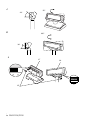
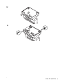
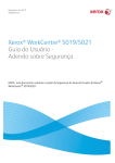
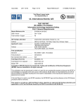
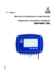
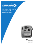
DM-D110/D210
User’s Manual . . . . . . . . . 1
用户手册 . . . . . . . . . . . . . 11
ユーザーズマニュアル . . 21
410809700
English
A
1
2
4
C
B
3
6
5
8
7
10
11
9
12
14
13
D
15
16
ii DM-D110/D210
English
E
F
17
22
18
19
21
20
G
24
23
26
27
28
25
29
30
H
31
32
I
33
34
35
36
DM-D110/D210 iii
English
J
90°
48°
K
330°
36°
L
37
ON
1
2
3 4
5
6
7 8
39
iv DM-D110/D210
38
English
M
2
1
1
N
1
2
DM-D110/D210 v
English
vi DM-D110/D210
English
English
DM-D110/D210
User’s Manual
Illustrations
All of the illustrations are at the beginning of this manual. They are identified by letters (A, B, C . . .). Some
of the illustrations have numbers in them. See the list below for the meaning of the numbers.
Illustration A:
1. Screen
2. DM-D110
3. DIP switch (rear side of the
display)
4. POWER switch (bottom of the
display)
5. Stand (DP-110)
Illustration B:
6. Plate
Illustration C:
7. Power Supply Connector
8. DM-D110 Cable
9. Power Supply Extension Cable
Connector
10. PC Connector
11. DM-D110 Connector
12. JP1
13. JP2
14. Printer Connector
Illustration D:
15. Connection to the DM-D110
Cable Printer
16. DP-502
Illustration E:
17. Screen
18. DM-D210
19. POWER Switch (rear side of the
display)
20. Stand (DP-210)
21. DIP Switch (bottom of the
display)
Illustration F:
22. Plate
Illustration G:
23. Power Supply Connector
24. DM-D210 Cable
25. Power Supply Extension Cable
Connector
26. PC Connector
27. DM-D210 Connector
28. JP1
29. JP2
30. Printer Connector
Illustration H:
31. Connection to the DM-D210
Printer Cable
32. DP-502
Illustration I:
33. Grooves (1 or more)
34. Inch Screws
35. Metric Screws
36. Screw for Attaching the
RS-232 Connector
Illustration L:
37. DM-D110
38. DM-D210
39. DIP switch
DM-D110/D210 User’s Manual 1
English
All rights reserved. No part of this publication may be reproduced, stored in a retrieval system, or
transmitted in any form or by any means, electronic, mechanical, photocopying, recording, or otherwise,
without the prior written permission of Seiko Epson Corporation. No patent liability is assumed with
respect to the use of the information contained herein. While every precaution has been taken in the
preparation of this book, Seiko Epson Corporation assumes no responsibility for errors or omissions.
Neither is any liability assumed for damages resulting from the use of the information contained herein.
Neither Seiko Epson Corporation nor its affiliates shall be liable to the purchaser of this product or third
parties for damages, losses, costs, or expenses incurred by purchaser or third parties as a result of:
accident, misuse, or abuse of this product or unauthorized modifications, repairs, or alterations to this
product, or (excluding the U.S.) failure to strictly comply with Seiko Epson Corporation’s operating and
maintenance instructions.
Seiko Epson Corporation shall not be liable against any damages or problems arising from the use of any
options or any consumable products other than those designated as Original Epson Products or Epson
Approved Products by Seiko Epson Corporation.
EPSON and ESC/POS are registered trademarks of Seiko Epson Corporation in the U.S. and other
countries.
NOTICE:
The contents of this manual are subject to change without notice.
Copyright © 2006 by Seiko Epson Corporation, Nagano, Japan.
EMC and Safety Standards Applied
EMC and Safety Standards Applied
Product Name:
DM-D110/DM-D210
Model Name:
M58DB/M59DB
The following standards are applied only to the display that is so labeled. (EMC is tested using the
EPSON power supplies.)
Europe:
CE marking
Safety:
EN 60950-1
North America:
EMI:
FCC/ICES-003 Class A
Safety:
UL 90650-1/CSA C22.2
No. 60950-1
Japan:
EMC:
VCCI Class A
Oceania:
EMC:
AS/NZS CISPR22 Class B
WARNING
You are cautioned that changes or modifications not expressly approved by SEIKO EPSON Corporation
could void your authority to operate the equipment.
CE Marking
The display conforms to the following Directives and Norms:
Directive 89/336/EEC
EN 55022 Class B
EN 55024
IEC 61000-4-2
IEC 61000-4-3
IEC 61000-4-4
IEC 61000-4-5
IEC 61000-4-6
IEC 61000-4-11
2 DM-D110/D210 User’s Manual
English
FCC Compliance Statement For American Users
This equipment has been tested and found to comply with the limits for a Class A digital device, pursuant
to Part 15 of the FCC Rules. These limits are designed to provide reasonable protection against harmful
interference when the equipment is operated in a commercial environment.
This equipment generates, uses, and can radiate radio frequency energy and, if not installed and used in
accordance with the instruction manual, may cause harmful interference to radio communications.
Operation of this equipment in a residential area is likely to cause harmful interference, in which case the
user will be required to correct the interference at his own expense.
FOR CANADIAN USERS
This Class A digital apparatus complies with Canadian ICES-003.
À l'intention des utilisateurs canadiens
Cet appareil numerique de la classe A est conforme a la norme NMB-003 du Canada.
GERAUSCHPEGEL
Gemas der Dritten Verordnung zum Geratesicherheitsgesetz (Maschinenlarminformations- Verordnung3. GSGV) ist der arbeitsplatzbezogene Gerausch-Emissionswert kleiner als 70 dB(A) (basierend auf ISO
7779).
Safety Precautions
This section presents important information intended to ensure safe and effective
use of this product. Please read this section carefully and store it in an accessible
location.
WARNING:
Shut down your equipment immediately if it produces smoke, a strange odor, or
unusual noise. Continued use may lead to fire. Immediately unplug the
equipment and contact your dealer or a Seiko Epson service center for advice.
Never attempt to repair this product yourself. Improper repair work can be
dangerous.
Never disassemble or modify this product. Tampering with this product may
result in injury or fire.
Be sure to use the specified power source. Connection to an improper power
source may cause fire.
Do not allow foreign matter to fall into the equipment. Penetration by foreign
objects may lead to fire.
If water or other liquid spills into this equipment, unplug the power cord
immediately, and then contact your dealer or a Seiko Epson service center for
advice. Continued usage may lead to fire.
CAUTION:
Do not connect cables in ways other than those mentioned in this manual.
Different connections may cause equipment damage and burning.
Be sure to set this equipment on a firm, stable, horizontal surface. The product
may break or cause injury if it falls.
Do not use in locations subject to high humidity or dust levels. Excessive humidity
and dust may cause equipment damage or fire.
Do not place heavy objects on top of this product. Never stand or lean on this
product. Equipment may fall or collapse, causing breakage and possible injury.
Do not connect multiple extension struts. If the device topples over, there is a
risk of damage or injury.
DM-D110/D210 User’s Manual 3
English
The horizontal rotating angle of the screen unit is limited by a stopper. Do not
apply excess force to rotate the screen unit past the limit set by the stopper.
Doing so may cause damage.
When you are attaching and detaching the cable, always check that the
power switches of the customer display and the unit that it is connected to are
turned off.
Take care when handling the customer display not to drop or knock it because
it has a built-in fluorescent display tube.
If you do not use this product for an extended period of time, always
disconnect the power cord for safety. If you move the product, ensure that the
power cord is disconnected and that all of the cables are disconnected before
moving it.
Do not use aerosol sprayers containing flammable gas inside or around this
product. Doing so may cause fire.
Part Names
See Illustrations A through H.
Option
Each of the options are used depending on the way the product is installed.
❏ Illustration A
DM-D110+DP-110 (Stand)
❏ Illustration D
DM-D110+DP-502 (TM Printer Connection Option)
❏ Illustration E
DM-D210+DP-210 (Stand)
❏ Illustration H
DM-D210+DP-502 (TM Printer Connection Option)
Unpacking
The following items are included with the standard specification Customer
Display. If any item is damaged, contact your dealer.
❏ Customer Display
DM-D110/DM-D210
❏ User’s Manual
Downloading Drivers, Utilities, and Manuals
Drivers, utilities, and manuals can be downloaded from one of the following
URLs.
For customers in North America, go to the following web site:
http://www.epsonexpert.com/ and follow the on-screen instructions.
For customers in other countries, go to the following web site:
http://www.epson-pos.com/
Select the product name from the “Select any product“ pulldown menu.
4 DM-D110/D210 User’s Manual
English
Precautions when Installing
❏
❏
❏
Ensure that the power switches of the customer display and the device that it
is connected to are turned off before connecting the cable.
The RS-232 connector of the stand (DP-110/210) is fitted with inch screws
(hex nuts). Replace these with the included metric screws if you need metric
screws. The inch screws and metric screws can be distinguished by the
presence or lack of grooves (see Illustration H).
Refer to the DM-D110 Technical Reference Guide or the DM-D210 Technical
Reference Guide for information on how to install the device.
Power Switch On/Off
Set the power switch on the base of the display unit to “|” to turn the power on
and execute the memory test. Nothing is displayed on the screen if the test finishes
normally. An error message is displayed if an error is detected.
Set the power switch to “O” to turn the power off.
Turn on the power to the customer display before turning on the power of the
computer, printer or other host devices.
Note:
If you are connecting to the USB model of the EPSON TM printer, always ensure that you
turn on the power to the customer display first. If you turn on the power to the customer
display too late, the system may not be able to detect the customer display.
Changing the Orientation of the Display Unit
The angle and direction of the display unit can be changed by pressing on the
struts with your hand while moving the display unit. The display unit will move
with only light pressure, so do not apply more pressure once the unit stops
moving. Applying excess force to move the display unit may cause damage.
When installed in the IR-700 or TM printer, there may be situations where the
display unit cannot be turned to the desired direction. In these situations, remove
the customer display and base unit, then adjust the position of the lug in the base
unit before reattaching.
The range of movement of the display unit is given in the following table. (DMD110: Illustration J, DM-D210: Illustration K)
DM-D110
DM-D210
Tilt
Maximum Angle 48° (4 Steps,
5 Positions)
Maximum Angle 36° (3 Steps,
4 Positions)
Horizontal
Rotation
Maximum Angle 90° (45° Left or Right) Maximum Angle 330°
DM-D110/D210 User’s Manual 5
English
Self Test
A self-test function is built into the DM-D110 and DM-D210. Execution of the selftest function can be configured using the DIP switches.
Self-Test Items
The self-test performs the following steps.
❏ Displays the version of the firmware
❏ Displays the configuration of the DIP switches
❏ Displays the configuration of the memory switches
❏ Introduces the display text
❏ Introduces each of the functions (brightness, blinking, scrolling, etc.)
Executing the Self Test
The self-test can be executed using the following procedure.
1. Turn off the power switch.
2. Set SW1-8 of DIP switch 1 to ON.
3. Turn on the power switch. The self-test screen is displayed.
If the self-test is completed successfully, the unit enters data reception standby
mode.
DIP Switches
The DIP switches configure the communication settings and whether a self-test is
required.
CAUTION:
Do not remove the DIP switch cover until after turning the power off. Removing
the cover while the power is turned on may damage the device.
Use the following procedure to configure the DIP switches.
1. Turn the power switch off.
2. Remove the DIP switch cover.
3. Use a pointed object to flip the switches.
4. Attach the cover and turn the power switch on.
DIP Switch 1 Functions
DSW1 No.
Function
ON
OFF
Default Setting
1-1
Received Error Data
Ignore
“?” Display
OFF
1-2
Receive Data Length
7bit
8bit
OFF
1-3
Parity
With Parity
No Parity
OFF
1-4
Parity Selection
Even
Odd
OFF
1-5
Communication Speed
Switching
1-6
Refer to “Transfer Speed Switching”
1-7
1-8
ON
OFF
ON
Execute Self-Test (*1)
Yes
(*1) Executes the self-test once only when the power is turned on.
6 DM-D110/D210 User’s Manual
No
OFF
English
Transfer Speed Switching
SW1-5
SW1-6
SW1-7
Transfer Speed
(bps)
2400
ON
ON
ON
OFF
ON
ON
4800
ON
OFF
ON
9600*1
OFF
OFF
ON
19200*2
ON
ON
OFF
38400
OFF
ON
OFF
57600
ON
OFF
OFF
115200
OFF
OFF
OFF
(Reserved)
*1 Default Setting
*2 Setting that is used when connecting to the USB model of the EPSON TM printer.
Jumper
There are jumpers in the stand (DP-110/210) that configure whether a TM printer
is connected to the DM-D110/210.
CAUTION:
Turn the power off before changing the jumper settings. Changing the jumper
settings while the power is turned on may damage the device.
Use the following procedure to change the jumper settings.
1. Turn off the power switch; then remove the power cable from the stand.
2. Remove the plate from the base of the stand. For the DM-D110, press the two
clips while lifting out the plate to remove the plate (see Illustration M). For
the DM-D210, remove the two screws to remove the plate.
3. Change the jumper settings.
4. Attach the plate. For the DM-D110, press down on the plate until it latches
into the clips on the stand (see Illustration N).
DM-D110
See Illustration C for the location of the jumpers.
JP1
JP2
Details
1-2
1-2
Use this setting if you are connecting and using both the TM printer and
this device.
(Default Setting)
2-3
2-3
Use this setting if you are using the DM-D stand in a stand-alone
configuration without connecting a TM printer.
DM-D110/D210 User’s Manual 7
English
DM-D210
See Illustration G for the location of the jumpers.
JP1
JP2
Details
1-2
1-2
Use this setting if you are connecting and using both the TM printer and
this device.
(Default Setting)
2-3
2-3
Use this setting if you are using the DM-D stand in a stand-alone
configuration without connecting a TM printer.
Specifications
DM-D110
Model
DM-D110
DM-D110 + DP110
Display type
Number of characters
displayed
40 characters (20 columns × 2 rows, 5 × 7 dot matrix)
Display color
Green (505 nm)
690 cd/m2
Brightness
Character classes
Alphanumeric: 95 characters
International characters: 37 characters
Graphic characters: 128 characters × 12 pages
Character composition
5 × 7 dot matrix, cursor
Character size
3.5 × 5.0 mm
Character pitch
Interface
5.2 mm
Standard
Connector
RS232C Compliant
RJ-45
D-Sub 25 pin (female)
Reliability
DC 11.4 V ~ 48 V
Power consumption
Approximately 2 W
Display
unit
165 (W) × 50.5 (D) × 69 (H) mm
Base unit
-
165 (W) × 110 (D) ×
63 (H) mm
78 (W) × 164 (D) ×
260 (H) mm
External
165 (W) × 50.5 (D) ×
69 (H) mm
165 (W) × 110 (D) ×
135 (H) mm
165 (W) × 164 (D) ×
331 or 451 (H) mm
Approximately 0.29 kg
Approximately 0.65 kg
Approximately 0.55 kg
Weight
Color
Cool white, Dark gray
Tilt angle
Horizontal rotation angle
Power supply
RJ-45
Lifespan 20,000 hours
Power supply voltage
External
dimensions
DM-D110 + DP502
Fluorescent tube display
Maximum 48° (4 steps)
-
Maximum 90°
Maximum 330°
Supplied by system
PS-180 (Option)
Supplied by TM printer
8 DM-D110/D210 User’s Manual
English
DM-D210
Model
DM-D210
DM-D210 + DP210
Display type
Number of characters
displayed
40 characters (20 columns × 2 rows, 5 × 7 dot matrix)
Display color
Green (505 nm)
700 cd/m2
Brightness
Character classes
Alphanumeric: 95 characters
International characters: 37 characters
Graphic characters: 128 characters × 12 pages
Character composition
5 × 7 dot matrix, comma/period/annunciator
Character size
6.5 × 11.3 mm
Character pitch
Interface
9.9 mm
Standard
Connector
RS232C Compliant
RJ-45
D-Sub 25 pin (female)
Reliability
DC 11.4 V ~ 48 V
Power consumption
Approximately 6 W
Display
unit
260 (W) × 60 (D) × 83 (H) mm
Base unit
-
260 (W) × 110 (D) ×
53 (H) mm
78 (W) × 164 (D) ×
260 (H) mm
External
260 (W) × 60 (D) ×
83 (H) mm
260 (W) × 110 (D) ×
383 or 503 (H) mm
260 (W) × 164 (D) ×
360 or 480 (H) mm
Approximately 0.6 kg
Approximately 0.98 kg
Approximately 0.85 kg
Weight
Color
Cool white, Dark gray
Tilt angle
Maximum 36° (3 steps)
Horizontal rotation angle
Power supply
RJ-45
Lifespan 20,000 hours
Power supply voltage
External
dimensions
DM-D210 + DP502
Fluorescent tube display
Maximum 330°
Supplied from system
PS-180 (Option)
Supplied by TM printer
DM-D110/D210 User’s Manual 9
English
10 DM-D110/D210 User’s Manual