1
Feature Package 3
TRIAD 1/2/3
Product
Description
a new dimension in business communications
STARPLUSTM Triad 1/2/3
Product Description Manual
Part Number: 8050-11
Issue 3.2 - March 2001
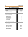
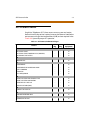
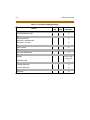
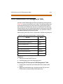
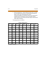
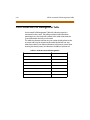
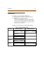
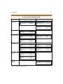
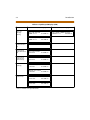
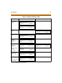
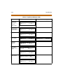
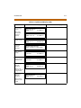
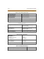
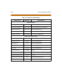
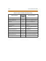
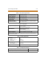
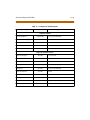
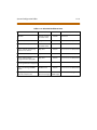
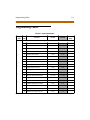
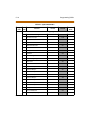
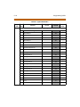
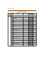
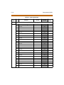
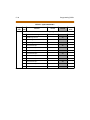
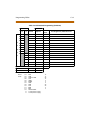
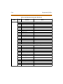
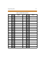
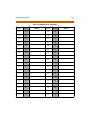
Issue
Release Date
2
8-99
Changes
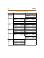
2.1
12-99
3
5-00
Feature Package 2 {FP2} enhancements have been added.
Manual content contains extensive revisions.
Feature Package 2 {FP2} updates have been added.
Manual content has been revised
Feature Package 3 {FP3} enhancements have been added.
Manual format has been changed.
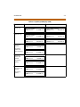
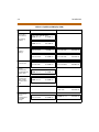
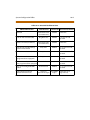
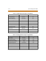
3.1
8-00
Feature Package 3 {FP3} enhancements have been clarified.
3.2
3-01
Manual content has been revised for correctness and clarity.
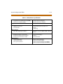
LIFE SUPPORT APPLICATIONS POLICY
VODAVI Technology, Inc. products are not authorized for and should not be used
within Life Support applications. Life Support systems are equipment intended to
support or sustain life and whose failure to perform when properly used in
accordance with instructions provided can be reasonably expected to result in
significant personal injury or death.
VODAVI Technology, Inc. warranty is limited to replacement of defective
components and does not cover injury to persons or property or other consequential
damages.
Copyright © 2001 VODAVI Technology, Inc.
All Rights Reserved
This material is copyrighted by VODAVI Technology, Inc., and may be duplicated by
Authorized Dealers only. Any unauthorized reproductions, use or disclosure of this
material, or any part thereof, is strictly prohibited and is a violation of the Copyright
Laws of the United States (17 U.S.C. Section 101 et. seq.).
VODAVI reserves the right to make changes in specifications at any time and without
notice. The information furnished by VODAVI in this material is believed to be accurate
and reliable, but is not warranted to be true in all cases.
STARPLUS TM and TRIADTM are registered trademarks of VODAVI Technology, Inc.
mlj/2001
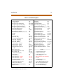
Contents
1
Introduction
Regulatory Information (U.S.A.) ...................................................................... 1-3
Telephone Company Notification .......................................................... 1-3
Incidence of Harm ........................................................................................ 1-4
Changes in Service ....................................................................................... 1-4
Maintenance Limitations ........................................................................... 1-4
Hearing Aid Compatibility ........................................................................ 1-4
UL/CSA Safety Compliance ....................................................................... 1-4
Notice of Compliance ................................................................................. 1-5
Toll Fraud and DISA Disclaimer ...................................................................... 1-5
2
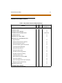
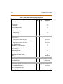
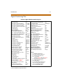
Digital Station Features
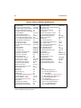
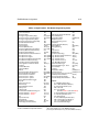
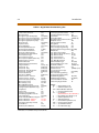
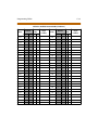
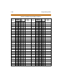
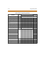
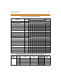
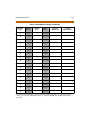
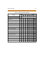
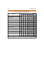
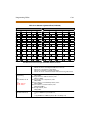
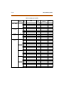
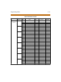
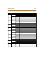
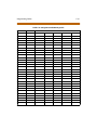
Station Features Index ....................................................................................... 2-3
Account Codes ..................................................................................................... 2-13
Account Codes - Forced .................................................................................... 2-13
Account Codes - Traveling COS (Verified) .................................................. 2-13
Answering Machine Emulation ...................................................................... 2-14
Attendant Assignment ...................................................................................... 2-14
Attendant Recall .................................................................................................. 2-14
Automatic Call Back Timer ............................................................................... 2-14
Automatic Call Distribution (ACD) ................................................................. 2-15
Agent Positions ............................................................................................. 2-15
Alternate ACD Group Assignments ....................................................... 2-16
ACD Group Member Status ...................................................................... 2-16
Guaranteed Message Announcement ................................................. 2-16
Incoming CO Direct Ringing .................................................................... 2-17
No-Answer Recall Timer ............................................................................. 2-17
No-Answer Retry Timer .............................................................................. 2-17
Overflow Station Assignments ................................................................ 2-17
Overflow Station Forwarding .................................................................. 2-18
PC/ACD Interface Trace .............................................................................. 2-18
Recorded Announcements (RAN) .......................................................... 2-18
Supervisor Positions .................................................................................... 2-19
ii
March 2001
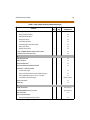
Supervisor/Agent Calls in Queue Status Display .............................. 2-20
Wrap-Up Timer Per ACD Group ............................................................... 2-20
Automatic Selection/Line Access .................................................................. 2-20
Automatic Night Service ................................................................................... 2-21
Automatic Pause Insertion With Speed Dial .............................................. 2-21
Automatic Privacy ............................................................................................... 2-21
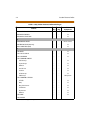
Background Music ............................................................................................... 2-22
Battery Back-Up (Memory) ............................................................................... 2-22
Busy Lamp Field (BLF) ........................................................................................ 2-22
Call Back .................................................................................................................. 2-22
Call Cost Display ................................................................................................... 2-22
Call Coverage ........................................................................................................ 2-23
Call Forward - Preset ........................................................................................... 2-24
Preset Call Forward - ACD, Voice Mail, UCD, or Hunt Groups ....... 2-24
Preset Call Forward - Off-Net .................................................................... 2-24
Preset Call Forward - Per CO Line ........................................................... 2-25
Preset Call Forward - Stations .................................................................. 2-25
Call Forward: Station .......................................................................................... 2-25
Call Forward - All Calls ................................................................................ 2-26
Call Forward - Busy ...................................................................................... 2-26
Call Forward - Busy/No Answer ............................................................... 2-26
Call Forward - Follow-Me ........................................................................... 2-26
Call Forward - No Answer .......................................................................... 2-26
Call Forward - Off-Net ................................................................................. 2-27
Call Park ................................................................................................................... 2-27
Call Pick-Up ............................................................................................................ 2-27
ACD/UCD Groups ......................................................................................... 2-27
Directed ........................................................................................................... 2-27
Group ................................................................................................................ 2-27
Call Transfer ........................................................................................................... 2-28
Calling Station Tone Mode ............................................................................... 2-28
Camp-On ................................................................................................................ 2-28
Camp-On Recall .................................................................................................... 2-29
Centrex Compatibility ........................................................................................ 2-29
Flex Button Programming ......................................................................... 2-29
Off-Hook Preference .................................................................................... 2-29
March 2001
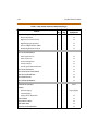
Private Line Appearance ............................................................................ 2-29
Programmable Flash Timer ...................................................................... 2-30
Programming ✳, #, and Hook-Flashes into Speed Dial .................. 2-30
Centrex/PBX Transfer ......................................................................................... 2-30
Class Of Service (COS) Day/Night ................................................................. 2-30
Class Of Service (COS) Station ......................................................................... 2-30
CO Line - Access ................................................................................................... 2-31
CO Line - Class Of Service (COS) ..................................................................... 2-31
CO Line - Control (Contact) .............................................................................. 2-31
CO Line - Distinctive Ring ................................................................................. 2-32
CO Line - Groups .................................................................................................. 2-32
CO Line - Identification ...................................................................................... 2-32
CO Line - Incoming Ringing Assignment .................................................... 2-33
CO Line - Loop Button ....................................................................................... 2-33
CO Line - Loop Supervision .............................................................................. 2-34
CO Line - Pool Button Operation ................................................................... 2-34
CO Line - Queuing ............................................................................................... 2-34
CO Line - Ringing Options ................................................................................ 2-34
CO Ring Detect ..................................................................................................... 2-35
Conference ............................................................................................................. 2-35
Multi-Party Conference .............................................................................. 2-35
Unsupervised Conference ......................................................................... 2-35
Conference Enable/Disable ...................................................................... 2-35
Database Printout (Dump) ............................................................................... 2-36
Database Upload/Download ........................................................................... 2-36
Dial By Name ......................................................................................................... 2-36
Dial Pulse Sending ............................................................................................... 2-36
Dialing Privileges ................................................................................................. 2-37
Direct Inward Dialing (DID) .............................................................................. 2-37
Direct Inward System Access (DISA) ............................................................. 2-37
Group Access ................................................................................................. 2-38
DISA Call Forwarding .................................................................................. 2-38
Programmable Access ................................................................................ 2-38
Station Access ................................................................................................ 2-38
Trunk-to-Trunk .............................................................................................. 2-38
Direct Station Selection (DSS) ......................................................................... 2-38
iii
iv
March 2001
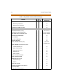
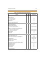
Direct Transfer Mode .......................................................................................... 2-39
Directory Dialing .................................................................................................. 2-39
Disable Outgoing CO Line Access ................................................................. 2-39
Do Not Disturb (DND) ........................................................................................ 2-40
One-Time Do Not Disturb ......................................................................... 2-40
DTMF Sending ...................................................................................................... 2-40
E911 Integration .................................................................................................. 2-40
End-to-End Signaling ......................................................................................... 2-41
Executive Override .............................................................................................. 2-41
Executive/Secretary Pairing ............................................................................. 2-41
External Night Ringing ....................................................................................... 2-42
Flash ......................................................................................................................... 2-42
Flash Rates (Programmable) ............................................................................ 2-42
Flexible Button Assignment ............................................................................ 2-42
Flexible Numbering ............................................................................................ 2-48
Forced Least Cost Routing (LCR) .................................................................... 2-48
Forward Override ................................................................................................. 2-48
Group Listening .................................................................................................... 2-48
Headset Compatibility ....................................................................................... 2-49
Headset Mode ....................................................................................................... 2-49
Hearing Aid Compatible ................................................................................... 2-49
Hold - Exclusive .................................................................................................... 2-49
Hold - Preference ................................................................................................. 2-50
Hold - Recall ........................................................................................................... 2-50
Hold - System ........................................................................................................ 2-50
Hot Keypad ............................................................................................................ 2-50
Hot Line/Ring Down ........................................................................................... 2-50
Hunt Groups .......................................................................................................... 2-51
Chaining .......................................................................................................... 2-51
Pilot Hunting .................................................................................................. 2-51
Station Hunting ............................................................................................. 2-51
ICLID/Caller ID ....................................................................................................... 2-52
Answered ICLID Table ................................................................................. 2-52
Caller-Entered ICLID Digits ........................................................................ 2-52
Caller ID Name/Number ............................................................................. 2-53
Calling Number/Name Display ................................................................ 2-53
March 2001
Incoming Number/Name for SMDR Records ..................................... 2-53
Unanswered Call Management Table ................................................... 2-54
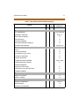
Idle Speaker Mode ............................................................................................... 2-54
Incoming CO Call Transfer ................................................................................ 2-54
Intercom Button(s) .............................................................................................. 2-55
Intercom Calling ................................................................................................... 2-55
Intercom Signaling Select ................................................................................. 2-56
Inter-Digit Time-Out ........................................................................................... 2-56
ISDN .......................................................................................................................... 2-56
Keyset Mode (Digital KTU Only) ..................................................................... 2-59
Last Number Redial (LNR) ................................................................................. 2-59
LCD Interactive Display ..................................................................................... 2-59
Least Cost Routing (LCR) ................................................................................... 2-59
Local Number/Name Translation Table ....................................................... 2-60
Mailbox Button(s) ................................................................................................ 2-60
Meet Me Page ....................................................................................................... 2-60
Message Waiting .................................................................................................. 2-61
Message Waiting Reminder Tone .................................................................. 2-61
Music-On-Hold ..................................................................................................... 2-61
Mute Key ................................................................................................................. 2-61
Name In Display ................................................................................................... 2-62
Name/Number Display At Idle ........................................................................ 2-62
Night Service ......................................................................................................... 2-62
Night Service Mode ............................................................................................ 2-63
Automatic Night Mode Operation ......................................................... 2-63
External Night Ringing ............................................................................... 2-63
Manual Operation ........................................................................................ 2-63
Night Class of Service (COS) ..................................................................... 2-63
Night Ringing Assignments ...................................................................... 2-63
Universal Night Answer (UNA) ................................................................ 2-63
Weekly Night Mode Schedule ................................................................. 2-64
Off-Hook Preference ........................................................................................... 2-64
Auto Feature Access .................................................................................... 2-64
Auto Line Access ........................................................................................... 2-64
Hot Line/Ring Down .................................................................................... 2-64
Intercom Access ............................................................................................ 2-64
v
vi
March 2001
User Programmable Preference .............................................................. 2-65
Off-Hook Signaling .............................................................................................. 2-65
Off-Hook Voice Over (OHVO) .......................................................................... 2-65
On-Hook Dialing .................................................................................................. 2-66
Online Programming ......................................................................................... 2-66
One-Touch Recording ........................................................................................ 2-66
Page/Relay Control ............................................................................................. 2-66
Paging ...................................................................................................................... 2-67
Access Restriction ......................................................................................... 2-67
External ............................................................................................................ 2-67
Internal ............................................................................................................. 2-67
Park Personal ......................................................................................................... 2-67
Pause Timer ........................................................................................................... 2-68
PBX Dialing Codes ............................................................................................... 2-68
Personalized Messages ...................................................................................... 2-68
Custom ............................................................................................................. 2-68
Date and Time Entry to Personalized Message(s) ............................. 2-69
Personalized Message Code on a Flex Key .......................................... 2-69
Scrollable Canned Messages .................................................................... 2-69
Preferred Line Answer ....................................................................................... 2-69
Privacy Release ..................................................................................................... 2-70
Per CO Line Option ...................................................................................... 2-70
Per Station Option ....................................................................................... 2-70
Private Line ............................................................................................................ 2-70
Pulse-to-Tone Switchover ................................................................................ 2-71
Range Programming .......................................................................................... 2-71
Remote Administration ..................................................................................... 2-71
Database Upload/Download ................................................................... 2-72
Remote System Monitor And Maintenance ............................................... 2-72
Maintenance .................................................................................................. 2-72
Monitor ............................................................................................................ 2-72
Repeat Redial ........................................................................................................ 2-73
Ring Tone (User Selectable) ............................................................................. 2-73
Save Number Redial (SNR) ............................................................................... 2-73
Single Line Telephone (SLT) Compatibility ................................................ 2-74
Speakerphone ....................................................................................................... 2-74
March 2001
Speed Bins/Chaining .......................................................................................... 2-74
Speed Dial - Flash ................................................................................................ 2-74
Speed Dial - Station ............................................................................................ 2-75
Speed Dial - System ............................................................................................ 2-75
Station ID Lock ...................................................................................................... 2-75
Station Message Detail Recording (SMDR) ................................................ 2-75
Station Relocation ............................................................................................... 2-76
T-1 Trunking .......................................................................................................... 2-76
Text Messaging (Silent Response) ................................................................. 2-77
Toll Restriction (Table Driven) ......................................................................... 2-77
Canned Toll Restriction .............................................................................. 2-77
Transfer Recall ....................................................................................................... 2-77
Uniform Call Distribution (UCD) ..................................................................... 2-78
Agent Queue Status Display .................................................................... 2-78
Alternate UCD Group Assignments ....................................................... 2-78
Auto Wrap-Up with Timer ......................................................................... 2-79
Incoming CO Direct Ringing .................................................................... 2-79
No-Answer Recall Timer ............................................................................. 2-79
No-Answer Retry Timer .............................................................................. 2-79
Overflow Station Forwarding Assignments ........................................ 2-80
Recorded Announcements (RAN) .......................................................... 2-80
Universal Day/Night Answer (UDA/UNA) ................................................... 2-80
Voice Mail Groups (VM) ..................................................................................... 2-81
Disconnect Signal ......................................................................................... 2-81
In-Band Signaling Integration ................................................................. 2-81
LCD Message(s) Indication ........................................................................ 2-82
Message Waiting Indication ..................................................................... 2-82
Tone Mode Calling Option ........................................................................ 2-82
Transfer/Forward .......................................................................................... 2-82
Transfer With ID Digits ................................................................................ 2-83
Volume Control Bar ............................................................................................. 2-83
3
Single Line Telephone Features
SLT Features Index .............................................................................................. 3-3
Account Codes ..................................................................................................... 3-5
Verified Account Codes/Traveling COS ................................................ 3-5
Automatic Call / Uniform Call Distribution ................................................. 3-5
vii
viii
March 2001
Automatic Line Access ....................................................................................... 3-5
Call Brokering ........................................................................................................ 3-6
Call Forward ........................................................................................................... 3-6
Call Pick-Up Directed .......................................................................................... 3-6
Call Pick-Up Group .............................................................................................. 3-6
Camp-On ................................................................................................................ 3-7
CO Line Queuing .................................................................................................. 3-7
Conference ............................................................................................................. 3-7
Conference With Personal Park ...................................................................... 3-7
Direct Outside Line Group Access ................................................................. 3-7
Direct Outside Line Ringing ............................................................................. 3-8
Do Not Disturb (DND) ........................................................................................ 3-8
Handset Receiver Gain ....................................................................................... 3-8
Intercom Calling ................................................................................................... 3-8
Loop Interrupt ...................................................................................................... 3-8
Message Waiting .................................................................................................. 3-9
Messages ................................................................................................................ 3-9
Personalized ................................................................................................... 3-9
Custom ............................................................................................................. 3-9
Name In Display ................................................................................................... 3-10
Off-Hook Preference ........................................................................................... 3-10
Paging ...................................................................................................................... 3-10
Access Restriction ......................................................................................... 3-10
External ............................................................................................................ 3-10
Internal ............................................................................................................. 3-10
Personal Park ......................................................................................................... 3-11
Speed Dial - Station ............................................................................................ 3-11
Speed Dial - System ............................................................................................ 3-11
Toll Restriction (Table Driven) ......................................................................... 3-11
Canned Toll Restriction .............................................................................. 3-12
Transfer .................................................................................................................... 3-12
Transfer Recall ....................................................................................................... 3-12
Universal Day/Night Answer (UDA/UNA) ................................................... 3-12
Voice Mail Groups (VM) ..................................................................................... 3-13
Message Waiting Indication ..................................................................... 3-13
4
Attendant Features
March 2001
Attendant Features - Index .............................................................................. 4-3
Attendant Features ............................................................................................. 4-4
911 Attendant Alert ..................................................................................... 4-4
Alternate Position ......................................................................................... 4-4
Automatic Night Mode .............................................................................. 4-4
Direct Station Selector - DSS Console ................................................... 4-4
Disable Outgoing Access ........................................................................... 4-4
Display Timer ................................................................................................. 4-5
Night Service .................................................................................................. 4-5
Off-Net Forward - Incoming CO Lines ................................................... 4-5
Override ........................................................................................................... 4-5
Position ............................................................................................................ 4-6
Preset Forward .............................................................................................. 4-6
Recall ................................................................................................................. 4-6
Special Ring Mode ....................................................................................... 4-6
Time and Date Programming .................................................................. 4-6
DSS/DLS Features ................................................................................................ 4-7
Busy Lamp Field Indicators ....................................................................... 4-7
Direct Station Calling .................................................................................. 4-7
Mapping Options ......................................................................................... 4-7
Messages - Custom ...................................................................................... 4-8
Release Key ..................................................................................................... 4-8
Transfer Search .............................................................................................. 4-8
Volume Control Bar (DKT) ......................................................................... 4-8
5
Electronic Telephone Operation
Introduction ........................................................................................................... 5-3
Account Codes ..................................................................................................... 5-7
Account Codes/Traveling COS (Verified) .................................................... 5-7
Answering a Recall .............................................................................................. 5-9
Answering Machine Emulation ...................................................................... 5-9
Notification Methods .................................................................................. 5-9
Mailbox Options ........................................................................................... 5-10
Automatic Call Distribution (ACD) ................................................................. 5-11
ACD Agent Help ............................................................................................ 5-11
Agent Login/Logout .................................................................................... 5-12
ACD Call Factor .............................................................................................. 5-14
ix
x
March 2001
ACD Call Qualification ................................................................................. 5-14
ACD Agent Queue Status Display .......................................................... 5-15
ACD Available/Unavailable Mode .......................................................... 5-17
ACD Overflow Station - Available/Unavailable Mode ..................... 5-18
ACD Overflow Station - Forwarding ...................................................... 5-18
Supervisor Login/Logout ........................................................................... 5-19
Supervisor Monitor With Barge-In ......................................................... 5-20
Supervisor Queue Status Display ........................................................... 5-21
ACD Group Member Status ...................................................................... 5-23
Zap Tone .......................................................................................................... 5-24
Background Music (Optional) ......................................................................... 5-24
Call Back .................................................................................................................. 5-24
Call Coverage ........................................................................................................ 5-25
Call Forward: Station .......................................................................................... 5-27
Call Forward - All Calls ................................................................................ 5-27
Call Forward - Busy ...................................................................................... 5-28
Call Forward - Busy/No Answer ............................................................... 5-28
Call Forward - Follow-Me ........................................................................... 5-29
Call Forward - No Answer .......................................................................... 5-31
Call Forward - Off-Net (via speed dial) .................................................. 5-31
Caller ID Name/Number .................................................................................... 5-32
Calling Station Tone Mode ............................................................................... 5-33
Call Park ................................................................................................................... 5-33
Call Park (by Station Number) ......................................................................... 5-33
Call Pick-Up: Group Pick-Up ............................................................................. 5-34
Call Transfer ........................................................................................................... 5-35
Camp-On ................................................................................................................ 5-36
CO Line Access ...................................................................................................... 5-36
CO Line Queuing .................................................................................................. 5-37
Conference Combinations ............................................................................... 5-38
Dial By Name ......................................................................................................... 5-39
Directed Call Pick-up .......................................................................................... 5-41
Directory Dialing - Stations .............................................................................. 5-41
Direct Inward System Access (DISA) ............................................................. 5-43
Do Not Disturb (DND) ........................................................................................ 5-44
One-Time Do Not Disturb ......................................................................... 5-44
March 2001
Exclusive Hold ....................................................................................................... 5-45
Executive Override .............................................................................................. 5-45
Executive/Secretary Transfer ........................................................................... 5-46
Flash ......................................................................................................................... 5-46
Flash On Intercom ............................................................................................... 5-46
Flexible Button Assignment ............................................................................ 5-46
Forward Override ................................................................................................. 5-48
Handset Receiver Gain ....................................................................................... 5-48
Hot Keypad ............................................................................................................ 5-48
Headset Mode ....................................................................................................... 5-49
ICLID Answered Call Management Table ................................................... 5-50
ICLID Unanswered Call Management Table .............................................. 5-50
Incoming CO Call Transfer ................................................................................ 5-52
Intercom Button(s) .............................................................................................. 5-52
Intercom Calling ................................................................................................... 5-54
Intercom Transfer ................................................................................................ 5-55
Last Number Redial (LNR) ................................................................................. 5-56
Least Cost Routing (LCR) ................................................................................... 5-56
Mailbox Button(s) ................................................................................................ 5-57
Meet Me Page ....................................................................................................... 5-58
Message Waiting .................................................................................................. 5-58
Mute Key ................................................................................................................. 5-59
Name In Display ................................................................................................... 5-60
Night Service ......................................................................................................... 5-61
Off-Hook Preference ........................................................................................... 5-61
Off-Hook Preference Programming ....................................................... 5-62
Programming PBX/Centrex Codes Onto Flex Button ..................... 5-62
One-Touch Recording ........................................................................................ 5-63
Outside Call ............................................................................................................ 5-65
Answering an Outside Call ........................................................................ 5-65
Making an Outside Call .............................................................................. 5-65
Placing an Outside Call on Hold .............................................................. 5-65
Paging ...................................................................................................................... 5-66
PBX/Centrex Transfer ......................................................................................... 5-66
Personal Park ......................................................................................................... 5-67
Personalized Messages ...................................................................................... 5-68
xi
xii
March 2001
Messages - Custom ...................................................................................... 5-69
Date & Time Entry on Personalized Message ..................................... 5-70
Personalized Message Code On A Flex Button .................................. 5-71
Scrollable Canned Messages .................................................................... 5-71
Pulse-To-Tone Switchover ............................................................................... 5-73
Repeat Redial ........................................................................................................ 5-73
Save Number Redial (SNR) ............................................................................... 5-74
Speakerphone ....................................................................................................... 5-75
Station Relocation ............................................................................................... 5-75
Station Speed Dial ............................................................................................... 5-76
Storing Speed Numbers .................................................................................... 5-76
System Speed Dial ............................................................................................... 5-78
Text Messaging (Silent Response) ................................................................. 5-78
Transferring CO Calls to a Station Forwarded to VM .............................. 5-80
Uniform Call Distribution (UCD) ..................................................................... 5-80
UCD Calls in Queue Display ...................................................................... 5-81
UCD Available/Unavailable Mode .......................................................... 5-81
UCD Overflow Station - Forwarding Assignments ........................... 5-82
Universal Day/Night Answer (UDA/UNA) ................................................... 5-82
Voice Mail Groups (VM) ..................................................................................... 5-84
VM Transfer with ID Digits ......................................................................... 5-85
VM Tone Mode Calling Option ................................................................ 5-86
Volume Controls .................................................................................................. 5-86
6
Digital Station Operation
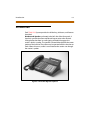
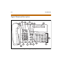
Introduction ........................................................................................................... 6-3
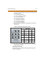
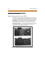
Digital Telephone Description ................................................................. 6-4
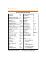
Digital Numbering Plan ............................................................................. 6-7
Account Codes ..................................................................................................... 6-8
Account Codes/Traveling COS (Verified) .................................................... 6-8
Answering a Recall .............................................................................................. 6-9
Answering Machine Emulation ...................................................................... 6-10
Notification Methods .................................................................................. 6-10
Mailbox Options ........................................................................................... 6-10
Automatic Call Distribution (ACD) ................................................................. 6-12
ACD Agent Help ............................................................................................ 6-12
Agent Login/Logout .................................................................................... 6-13
March 2001
xiii
ACD Agent Queue Status Display .......................................................... 6-15
ACD Available/Unavailable Mode .......................................................... 6-16
ACD Call Factor .............................................................................................. 6-17
ACD Call Qualification ................................................................................. 6-17
ACD Group Member Status ...................................................................... 6-18
ACD Overflow Station - Available/Unavailable Mode ..................... 6-19
ACD Overflow Station - Forwarding ...................................................... 6-19
Supervisor Login/Logout ........................................................................... 6-20
Supervisor Monitor With Barge-In ......................................................... 6-21
Supervisor Queue Status Display ........................................................... 6-22
Zap Tone .......................................................................................................... 6-23
Background Music (Optional) ......................................................................... 6-23
Call Back .................................................................................................................. 6-24
Call Coverage ........................................................................................................ 6-24
Call Forward: Station .......................................................................................... 6-26
Call Forward - All Calls ................................................................................ 6-26
Call Forward - Busy ...................................................................................... 6-27
Call Forward - Busy/No Answer ............................................................... 6-28
Call Forward - Follow-Me ........................................................................... 6-28
Call Forward - No Answer .......................................................................... 6-31
Call Forward - Off-Net (via speed dial) .................................................. 6-31
Caller ID Name/Number .................................................................................... 6-32
Calling Station Tone Mode ............................................................................... 6-33
Call Park ................................................................................................................... 6-33
Call Park (by Station Number) ......................................................................... 6-33
Call Pick-Up ............................................................................................................ 6-34
Directed ........................................................................................................... 6-34
Group ................................................................................................................ 6-35
Call Transfer ........................................................................................................... 6-35
Camp-On ................................................................................................................ 6-36
CO Line Access ...................................................................................................... 6-37
CO Line Queuing .................................................................................................. 6-37
Conference Combinations ............................................................................... 6-38
Dial By Name ......................................................................................................... 6-40
Directory Dialing - Stations .............................................................................. 6-41
Direct Inward System Access (DISA) ............................................................. 6-44
xiv
March 2001
Do Not Disturb (DND) ........................................................................................ 6-44
One-Time Do Not Disturb ......................................................................... 6-45
Executive Override .............................................................................................. 6-45
Executive/Secretary Pairing ............................................................................. 6-46
Flash ......................................................................................................................... 6-47
Flexible Button Assignment ............................................................................ 6-47
Forward Override ................................................................................................. 6-50
Group Listening .................................................................................................... 6-50
Headset Mode ....................................................................................................... 6-51
Hold - Exclusive .................................................................................................... 6-51
Hot Keypad ............................................................................................................ 6-52
ICLID Answered Call Management Table ................................................... 6-52
ICLID Unanswered Call Management Table .............................................. 6-53
Incoming CO Call Transfer ................................................................................ 6-54
Intercom Buttons ................................................................................................. 6-55
Intercom Calling ........................................................................................... 6-57
Intercom Transfer ......................................................................................... 6-58
Keyset Mode .......................................................................................................... 6-58
Keyset Self Test .............................................................................................. 6-60
Last Number Redial (LNR) ................................................................................. 6-60
LCD Display - Contrast ....................................................................................... 6-60
Least Cost Routing (LCR) ................................................................................... 6-61
Mailbox Buttons ................................................................................................... 6-61
Meet Me Page ....................................................................................................... 6-62
Message Waiting .................................................................................................. 6-63
Mute Key ................................................................................................................. 6-63
Name in Display ................................................................................................... 6-64
Night Service ......................................................................................................... 6-65
Off-Hook Preference ........................................................................................... 6-65
Off-Hook Preference Programming ....................................................... 6-66
Programming PBX/Centrex Codes Onto Flex Button ..................... 6-66
Off-Hook Voice Over (OHVO) .......................................................................... 6-67
One-Touch Recording ........................................................................................ 6-70
Outside Call ............................................................................................................ 6-72
Answering an Outside Call ........................................................................ 6-72
Making an Outside Call .............................................................................. 6-72
March 2001
Placing an Outside Call on Hold .............................................................. 6-72
Paging ...................................................................................................................... 6-73
Park - Personal ...................................................................................................... 6-74
PBX/Centrex Transfer ......................................................................................... 6-75
Personalized Messages ...................................................................................... 6-75
Personalized Messages - Custom ........................................................... 6-76
Date and Time Entry on Personalized Message ................................ 6-76
Personalized Message Code on a Flex Button ................................... 6-78
Scrollable Canned Messages .................................................................... 6-78
Pulse-to-Tone Switchover ................................................................................ 6-79
Repeat Redial ........................................................................................................ 6-80
Ring Tone ................................................................................................................ 6-81
Save Number Redial (SNR) ............................................................................... 6-83
Speakerphone ....................................................................................................... 6-84
Speed Dial .............................................................................................................. 6-84
Station Speed Numbers ............................................................................. 6-84
System Speed Numbers ............................................................................. 6-85
Station Relocation ............................................................................................... 6-86
Text Messaging (Silent Response) ................................................................. 6-87
Uniform Call Distribution (UCD) ..................................................................... 6-89
UCD Calls In Queue Display ...................................................................... 6-89
UCD Overflow Station - Forwarding Assignments ........................... 6-90
Universal Day/Night Answer (UDA/UNA) ................................................... 6-90
Voice Mail Groups (VM) ..................................................................................... 6-92
VM Transfer with ID Digits ......................................................................... 6-92
VM Tone Mode Calling Option ................................................................ 6-93
Volume Control Bar (DKT) ................................................................................. 6-94
7
Single Line Telephone Operation
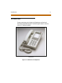
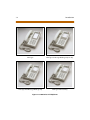
Introduction ........................................................................................................... 7-3
Account Codes ..................................................................................................... 7-6
Automatic Call Distribution (ACD) ................................................................. 7-6
Agent Login/Logout .................................................................................... 7-6
ACD Agent HELP ........................................................................................... 7-8
ACD/UCD Available/Unavailable Mode ............................................... 7-8
Automatic Line Access ....................................................................................... 7-8
Call Back .................................................................................................................. 7-9
xv
xvi
March 2001
Call Brokering ........................................................................................................ 7-9
Call Forward ........................................................................................................... 7-9
Call Forward - Follow-Me ........................................................................... 7-10
Calling Station Tone Mode Option ................................................................ 7-11
Call Park - Personal .............................................................................................. 7-12
Call Park (by Station Number) ......................................................................... 7-12
Call Park (System) ................................................................................................ 7-13
Call Pick-up Directed .......................................................................................... 7-13
Call Pick-Up Group .............................................................................................. 7-14
Call Transfer ........................................................................................................... 7-14
Camp-On ................................................................................................................ 7-14
Clear Call Forward, DND, Personalized Messages .................................... 7-15
CO Line Direct Access ........................................................................................ 7-15
CO Line Queuing .................................................................................................. 7-15
Conference ............................................................................................................. 7-15
Conference With Personal Park ...................................................................... 7-16
Direct Outside Line Access ............................................................................... 7-16
Do Not Disturb (DND) ........................................................................................ 7-16
Handset Receiver Gain ....................................................................................... 7-17
Intercom Calling ................................................................................................... 7-17
Least Cost Routing (LCR) ................................................................................... 7-18
Meet Me Page ....................................................................................................... 7-18
Message Waiting .................................................................................................. 7-19
Off-Hook Preference ........................................................................................... 7-19
Personalized Messages ...................................................................................... 7-20
Paging ...................................................................................................................... 7-20
Programming Names - LCD Display ............................................................. 7-21
Speed Dial - Station ............................................................................................ 7-21
Speed Dial - Storing Station Numbers ......................................................... 7-21
Speed Dial - System ............................................................................................ 7-22
Transfer (PBX/Centrex ) ..................................................................................... 7-22
Universal Day/Night Answer (UDA/UNA) ................................................... 7-22
Voice Mail Operation .......................................................................................... 7-23
8
Digital Attendant Operations
Introduction ........................................................................................................... 8-3
Attendant Unavailable (Alternate Position) ............................................... 8-7
March 2001
xvii
Call Hold .................................................................................................................. 8-8
Call Park ................................................................................................................... 8-8
CO Lines Off-Net Forward - Incoming (via Speed Dial) .......................... 8-8
Day/Night/Special Mode .................................................................................. 8-9
Directory Dialing .................................................................................................. 8-10
ICLID Answered Call Management Table ................................................... 8-16
ICLID Unanswered Call Management Table .............................................. 8-17
Messages - Custom ............................................................................................. 8-18
Outgoing Access - Attendant Disable .......................................................... 8-19
Override .................................................................................................................. 8-20
Outside Call - Answer ......................................................................................... 8-20
Outside Call - Place .............................................................................................. 8-20
Recall ........................................................................................................................ 8-20
Release Button ...................................................................................................... 8-21
Setting System Time and Date ....................................................................... 8-21
Software Version Display .................................................................................. 8-21
Speed Dial - System Storing ............................................................................ 8-22
9
Liquid Crystal Displays
Introduction ........................................................................................................... 9-3
10 Triad 1/2 System Configuration
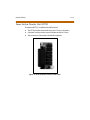
Triad 1/2 General Description ......................................................................... 10-3
System Hardware Preferences ................................................................. 10-3
System Control and Flexibility ................................................................. 10-3
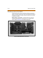
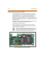
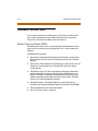
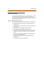
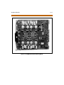
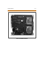
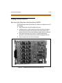
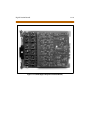
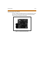
Triad 1 Common Control Equipment ........................................................... 10-4
Basic Key Service Unit (BKSU) ................................................................... 10-4
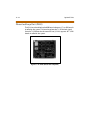
Expansion Key Service Unit (EKSU) ........................................................ 10-4
Power Supply (PSU) ..................................................................................... 10-4
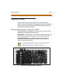
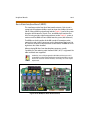
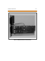
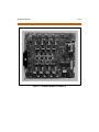
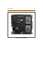
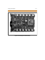
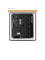
Triad 2 Common Control Equipment ........................................................... 10-8
Basic Key Service Unit (BKSU) ................................................................... 10-8
Expansion Key Service Unit (EKSU) ........................................................ 10-8
Power Supply (PSU) ..................................................................................... 10-8
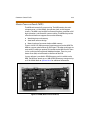
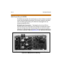
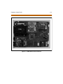
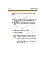
Common Control Cards ..................................................................................... 10-8
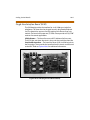
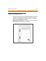
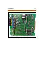
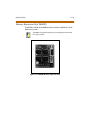
Master Processor Board (MPB) ................................................................. 10-9
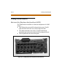
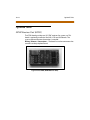
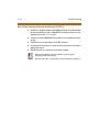
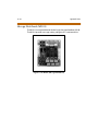
Miscellaneous Service Unit (MISU) ......................................................... 10-10
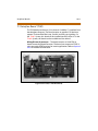
Peripheral Boards ................................................................................................ 10-11
xviii
March 2001
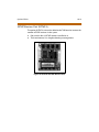
CO Line Interface Board - Loop Start (LCOB) ...................................... 10-11
DID Trunk Board (DIDB) ............................................................................. 10-12
T-1 Interface Board (T1IB) .......................................................................... 10-13
Primary Rate Interface Board (PRIB) ....................................................... 10-14
Basic Rate Interface Board (BRIB) ............................................................ 10-15
Analog Station Boards ....................................................................................... 10-16
Electronic Key Telephone Interface Board (ETIB) .............................. 10-16
Single Line Interface Board (SLIB) ........................................................... 10-17
Digital Station Boards ........................................................................................ 10-18
Digital Telephone Interface Board (DTIB) ............................................ 10-18
Analog Station Instruments ............................................................................. 10-19
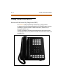
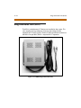
Enhanced Electronic Key Telephone (EKT) .......................................... 10-19
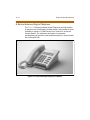
Executive Electronic Key Telephone (EKT) .......................................... 10-20
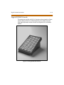
Electronic DSS/DLS Console ..................................................................... 10-21
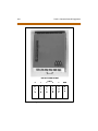
Digital Station Instruments .............................................................................. 10-22
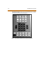
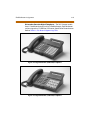
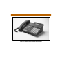
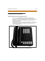
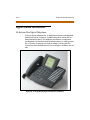
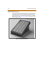
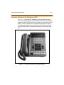
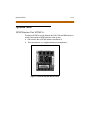
30-Button Elite Digital Telephone .......................................................... 10-22
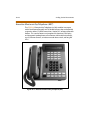
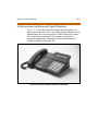
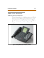
24-Button Executive/Enhanced Digital Telephones ........................ 10-23
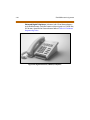
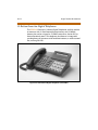
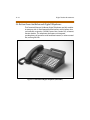
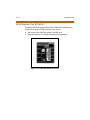
12-Button Executive Digital Telephones ............................................. 10-24
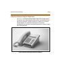
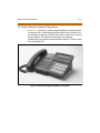
8-Button Enhanced Digital Telephones ............................................... 10-25
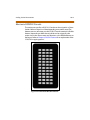
Digital DSS/DLS Console ............................................................................ 10-26
Single Line Adapter (SLA) ................................................................................. 10-27
Optional Units ....................................................................................................... 10-28
DTMF Receiver Unit (DTRU) ...................................................................... 10-28
DTMF Receiver Unit (DTMF-A) ................................................................. 10-29
Serial Interface Unit (SIU) ........................................................................... 10-30
Power Failure Transfer Unit (PFTU) ........................................................ 10-31
Ring Generator Unit (RGU) ........................................................................ 10-32
Modem Unit (MODU) .................................................................................. 10-33
Phase Lock Loop Unit (PLLU) ................................................................... 10-34
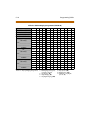
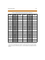
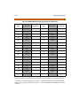
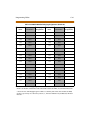
System Configuration Tables .......................................................................... 10-35
11 Triad 3 System Configuration
Triad 3 General Description ............................................................................. 11-3
System Hardware Preferences ................................................................. 11-3
System Control and Flexibility ................................................................. 11-3
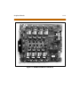
Common Control Equipment ......................................................................... 11-4
Basic Cabinet (BKSU) ................................................................................... 11-4
March 2001
xix
Expansion Cabinet (EKSU1) ...................................................................... 11-4
Expansion Cabinet (EKSU2) ...................................................................... 11-4
Battery Charging Unit (BCU) ..................................................................... 11-4
DC/DC Converter Unit (DCCU) ................................................................. 11-5
PS-10/PS15 Power Supply (PS) ................................................................ 11-5
Ring Generator Unit (RGU) ........................................................................ 11-5
Common Control Cards ..................................................................................... 11-8
Master Processor Board (MPB) ................................................................. 11-8
Miscellaneous Service Unit (MISU) ......................................................... 11-10
Peripheral Boards ................................................................................................ 11-12
Loop Start (LCOB) Trunk Board ............................................................... 11-12
Ground Start (GCOB) Trunk Board ......................................................... 11-14
DID Trunk Board (DIDB) ............................................................................. 11-16
T-1 Interface Board (T1IB) .......................................................................... 11-18
Primary Rate Interface Board (PRIB) ....................................................... 11-20
Basic Rate Interface Board (BRIB) ............................................................ 11-22
Basic Rate Interface Expansion Board (BRIB-E) .................................. 11-24
Analog Station Boards ....................................................................................... 11-25
Electronic Key Telephone Interface Board (ETIB) .............................. 11-25
Single Line Interface Board (SLIB) ........................................................... 11-26
Digital Station Boards ........................................................................................ 11-28
Digital Telephone Interface Board (DTIB) ............................................ 11-28
Digital Telephone Interface Board Expansion (DTIBE) .................... 11-30
Analog Station Instruments ............................................................................. 11-32
Enhanced Electronic Key Telephone (EKT) .......................................... 11-32
Executive Electronic Key Telephone (EKT) .......................................... 11-33
Electronic DSS/DLS Console ..................................................................... 11-34
Digital Station Instruments .............................................................................. 11-35
30-Button Elite Digital Telephone .......................................................... 11-35
24-Button Executive/Enhanced Digital Telephones ........................ 11-36
12- Button Executive Digital Telephones ............................................ 11-37
8-Button Enhanced Digital Telephone ................................................. 11-38
Digital DSS/DLS Console ............................................................................ 11-39
Single Line Adapter (SLA) ................................................................................. 11-40
Optional Units ....................................................................................................... 11-41
DTMF Receiver Unit (DTMF-A) ................................................................. 11-41
xx
March 2001
DTMF Receiver Unit (DTMF-B) ................................................................. 11-42
Serial Interface Unit (SIU2) ........................................................................ 11-43
Phase Lock Loop Unit (PLLU) ................................................................... 11-44
Memory Expansion Unit (MEMU) ........................................................... 11-45
Message Wait Board (MSG12) .................................................................. 11-46
Power Failure Transfer Unit (PFTU) ........................................................ 11-47
Ring Generator Unit (RGU) ............................................................................... 11-48
System Configuration Tables .......................................................................... 11-49
A
ICLID General Description
System Configuration ........................................................................................ A-3
Functional Performance .................................................................................... A-4
Calling Number/Name Display ................................................................ A-4
Incoming Number/Name SMDR ............................................................. A-6
Unanswered Call Management ............................................................... A-6
Local Name Translation .............................................................................. A-6
B
Part Numbers
List of Equipment ................................................................................................ B-3
C
Customer Database Programming Worksheets
Programming Tables .......................................................................................... C-3
March 2001
xxi
Figures
Default Button Map (Executive and Enhanced Models) .................................. 2-44
Digital Executive (24-Button) Telephone ............................................................... 2-45
Digital Executive (12-Button) Telephone ............................................................... 2-45
Digital Enhanced (8-Button) Telephone ................................................................ 2-46
DSS Console Map #1 ...................................................................................................... 4-9
DSS Console Map #2 ...................................................................................................... 4-10
DSS Console Map #3 ...................................................................................................... 4-11
DSS Console Map #4 ...................................................................................................... 4-12
DSS Console Map #5 ...................................................................................................... 4-13
Executive Electronic Key Telephone Default Button Map ............................... 5-5
Other Key Pad Codes (Name) ..................................................................................... 5-60
Other Key Pad Codes (Date and Time) ................................................................... 5-70
Executive Digital Telephone ....................................................................................... 6-3
Digital Key Telephone ................................................................................................... 6-4
Key Pad - Dial By Name ................................................................................................. 6-40
Key Pad - Directory Dialing ......................................................................................... 6-42
Other Key Pad Codes (Name) ..................................................................................... 6-64
Other Key Pad Codes (Date and Time) ................................................................... 6-77
2700 Series SLT Telephones ....................................................................................... 7-3
2700 Series SLT Telephones ....................................................................................... 7-4
Attendant Digital Display Telephone ...................................................................... 8-5
Triad 1 System Diagram ............................................................................................... 10-5
Triad 1 Default Card Layout ........................................................................................ 10-6
Triad 2 Default Card Layout ........................................................................................ 10-7
MPB (Master Processor Board) ................................................................................... 10-9
MISU (Miscellaneous Service Unit) ........................................................................... 10-10
LCOB (CO/FX/WATS Trunk Board) ............................................................................ 10-11
DIDB (Direct Inward Dialing) ...................................................................................... 10-12
T1IB (T-1 Interface Board) ............................................................................................ 10-13
PRIB (Primary Rate Interface Board) ......................................................................... 10-14
BRIB (Basis Rate Interface Board) .............................................................................. 10-15
ETIB (Electronic Telephone Interface Board) ........................................................ 10-16
xxii
March 2001
SLIB (Single Line Interface Board) ............................................................................. 10-17
DTIB12 & DTIB24 (Digital Telephone Interface Board) ...................................... 10-18
Enhanced Electronic Key Telephone (EKT) ............................................................ 10-19
Executive Electronic Key Telephone (EKT) ............................................................ 10-20
Electronic DSS/DLS Console ....................................................................................... 10-21
Large Display Digital Telephone (30-Button) ....................................................... 10-22
Executive Digital Telephone (24-Button) ............................................................... 10-23
Executive Digital Telephone (12-Button) ............................................................... 10-24
Enhanced Digital Telephone (8-Button) ................................................................ 10-25
Digital DSS/DLS Console .............................................................................................. 10-26
SLA (Single Line Adapter) ............................................................................................ 10-27
DTRU (DTMF Receiver Unit) ........................................................................................ 10-28
DTMF-A (DTMF Receiver Unit) ................................................................................... 10-29
SIU (Serial Interface Unit) ............................................................................................. 10-30
PFTU (Power Failure Transfer Unit) .......................................................................... 10-31
RGU (Ring Generator Unit) .......................................................................................... 10-32
MODU (Modem Unit) .................................................................................................... 10-33
PLLU (Phase Lock Loop Unit) ..................................................................................... 10-34
Triad 3 System Diagram ............................................................................................... 11-6
Triad 3 Default Card Layout ........................................................................................ 11-7
MPB (Master Processor Board) ................................................................................... 11-9
MISU (Miscellaneous Service Unit Board) .............................................................. 11-11
LCOB (CO/FX/WATS Trunk Board) ............................................................................ 11-13
GCOB (CO/FX/WATS Trunk Board) ........................................................................... 11-15
DIDB (Direct Inward Dialing Board) ......................................................................... 11-17
T1IB (T-1 Trunk Board) .................................................................................................. 11-19
PRIB (PRI Trunk Board) .................................................................................................. 11-21
BRIB (BRI Trunk Board) .................................................................................................. 11-23
ETIB (Electronic Telephone Interface Board) ........................................................ 11-25
SLIB (Single Line Interface Board) ............................................................................. 11-27
DTIB (Digital Telephone Interface Board) .............................................................. 11-29
DTIBE (Digital Telephone Interface Board Expansion) ...................................... 11-31
Enhanced Electronic Key Telephone (EKT) ............................................................ 11-32
Executive Electronic Key Telephone (EKT) ............................................................ 11-33
Electronic DSS/DLS Console ....................................................................................... 11-34
Large Display Digital Telephone (30-Button) ....................................................... 11-35
March 2001
xxiii
Executive Digital Telephone (24-Button) ............................................................... 11-36
Executive Digital Telephone (12-Button) ............................................................... 11-37
Enhanced Digital Telephone (8-Button) ................................................................ 11-38
Digital DSS/DLS Console .............................................................................................. 11-39
SLA (Single Line Adapter) ............................................................................................ 11-40
DTMF-A (DTMF Receiver Unit) ................................................................................... 11-41
DTMF-B (DTMF Receiver Unit) .................................................................................... 11-42
SIU2 (Serial Interface Unit) ........................................................................................... 11-43
PLLU (Phase Lock Loop Unit) ..................................................................................... 11-44
MEMU (Memory Expansion Unit) .............................................................................. 11-45
MSG12 (Message Wait Board) .................................................................................... 11-46
PFTU (Power Failure Transfer Unit) .......................................................................... 11-47
RGU (Ringer Generator Unit) ...................................................................................... 11-48
CTI System Configuration ............................................................................................ A-3
xxiv
March 2001
xxiv
March 2001
Tables
Key Station Features/Software Packages .............................................................. 2-3
Flex Button Programming Codes ............................................................................. 2-47
SLT Features/Software Packages .............................................................................. 3-3
Attendant Features/Software Packages ................................................................. 4-3
Electronic Telephone Numbering Plan .................................................................. 5-6
ICLID Answered Call Buttons ...................................................................................... 5-50
ICLID Unanswered Call Buttons ................................................................................ 5-51
Digital Key Telephone Buttons .................................................................................. 6-5
Digital Telephone Numbering Plan ......................................................................... 6-7
Digital Station - Flex Button Programming Codes ............................................. 6-49
ICLID Answered Call Table - Button Functions .................................................... 6-52
ICLID Unanswered Call Table - Button Functions ............................................... 6-53
Ringing Choices .............................................................................................................. 6-82
SLT Numbering Plan ...................................................................................................... 7-5
Digital Attendant Numbering Plan .......................................................................... 8-6
ICLID Answered Call Management .......................................................................... 8-16
ICLID Unanswered Call Management ..................................................................... 8-17
Liquid Crystal Displays (LCD) ...................................................................................... 9-3
Digital System Capacity ............................................................................................... 10-35
Electrical Specifications ................................................................................................ 10-37
Environmental Specifications .................................................................................... 10-38
Loop Limits ....................................................................................................................... 10-38
Dialing Specifications .................................................................................................... 10-38
FCC Registration Numbers .......................................................................................... 10-38
Trunk Ordering Info: Public Network Lines ........................................................... 10-39
Physical Dimensions and Weight ............................................................................. 10-39
Miscellaneous Specifications ..................................................................................... 10-40
Electronic Telephone Audible Signals .................................................................... 10-41
Single Line Audible Signals ......................................................................................... 10-42
Digital Station Visual Signals - CO Line Buttons .................................................. 10-43
Digital Station Visual Signals - DSS/BLF Buttons ................................................. 10-43
Digital Station Visual Signals - Feature/Function Buttons ............................... 10-44
Signals to CALLED Station (Digital Station) .......................................................... 10-45
Signals to CALLING Station (Digital Station) ......................................................... 10-46
March 2001
xxv
Voice Mail Confidence Tones ..................................................................................... 10-47
Digital System Capacity ............................................................................................... 11-49
Electrical Specifications ................................................................................................ 11-50
Environmental Specifications .................................................................................... 11-51
Loop Limits ....................................................................................................................... 11-51
Dialing Specifications .................................................................................................... 11-51
FCC Registration Numbers .......................................................................................... 11-51
Trunk Ordering Info: Public Network/Private Lease Lines ............................... 11-52
Physical Dimensions and Weight ............................................................................. 11-52
Miscellaneous Specifications ..................................................................................... 11-53
Electronic Telephone Audible Signals .................................................................... 11-54
Single Line Audible Signals ......................................................................................... 11-55
Digital Station Visual Signals - CO Line Buttons .................................................. 11-56
Digital Station Visual Signals - DSS/BLF Buttons ................................................. 11-56
Digital Station Visual Signals - Feature/Function Buttons ............................... 11-57
Signals to Called Station (Digital Station) .............................................................. 11-58
Signals to Calling Station (Digital Station) ............................................................ 11-58
Voice Mail Confidence Tones ..................................................................................... 11-59
Triad 1/2 Part Numbers ................................................................................................ B-3
Triad 3 Part Numbers .................................................................................................... B-5
System Parameters ........................................................................................................ C-3
Directory Dialing Defaults (FLASH 23) .................................................................... C-31
Cabinet/Card Programming (FLASH 24) ................................................................ C-35
Hunt Group Parameters (FLASH 30) ........................................................................ C-36
Verified Account Codes (FLASH 31) ......................................................................... C-37
CO Line Programming (FLASH 40) ........................................................................... C-42
Miscellaneous CO Parameters & Timers (FLASH 40/41) ................................... C-43
CO Line Ringing Assignments (FLASH 40) ............................................................. C-44
DID/ICLID Default Ringing Assignments (FLASH 43) ......................................... C-45
DID Default Table Entry (FLASH 44) ......................................................................... C-53
Station Programming (FLASH 50) ............................................................................ C-59
Button Assignment Chart (FLASH 50) ..................................................................... C-61
System Speed Dial Numbers ...................................................................................... C-62
ACD Group Parameters (FLASH 60) ......................................................................... C-64
UCD Group Parameters ................................................................................................ C-69
Voice Mail Group Parameters ..................................................................................... C-70
xxvi
March 2001
Mailbox Table (FLASH 68) ............................................................................................ C-71
Exception Tables (FLASH 70) ...................................................................................... C-79
Least Cost Routing (FLASH 75) .................................................................................. C-81
Route List Table ............................................................................................................... C-82
Insert/Delete Tables ....................................................................................................... C-84
3-Digit Area/Office Code Route List Table ............................................................. C-86
6-Digit Area Code/Routing Table ............................................................................. C-87
6-Digit Office Code Table ............................................................................................ C-88
xxvii
March 2001
1
Introduction
This manual provides the information necessary to operate and
maintain the STARPLUS Triad 1/2/3 System. The described features
are based on the current software release. If any of these features do
not work on your system, call your sales representative regarding
upgrading your system.
Regulatory Information (U.S.A.)
1-3
Regulatory Information (U.S.A.)
The Federal Communications Commission (FCC) established rules to
allow the direct connection of the Triad 1/2/3 Systems to a telephone
network. Certain actions must be undertaken or understood before the
connection of customer provided equipment is completed.
5XX = ACD Group (550-565)
Telephone Company Notification
Before connecting Triad 1/2/3 System to the telephone network, the local
serving telephone company must be given advance notice of intention
to use customer provided equipment, and must be provided with the
following information:
Telephone Numbers
The telephone numbers to be connected to the system.
Triad 1/2 System Information
The Ringer Equivalence Number also located on the KSU: 1.3B
The USOC jack required for direct interconnection with the telephone
network: RJ11C
Triad 3 System Information
The Ringer Equivalence Number also located on the KSU: 1.3B
The USOC jack required for direct interconnection with the telephone
network: RJ21X
FCC Registration Numbers:
For systems configured as a key system: (button appearances)
DLPKOR-24039-KF-E
For systems configured as a Hybrid system: (dial access codes)
DLPKOR-24026-MF-E
1-4
Regulatory Information (U.S.A.)
Incidence of Harm
If the telephone company determines that the customer provided
equipment is faulty and possibly causing harm or interruption to the
telephone network, it should be disconnected until repairs can be made.
If this is not done, the telephone company may temporarily disconnect
service.
Changes in Service
The local telephone company may make changes in its communications
facilities or procedures. If these changes affect the use of the Triad 1/2/3
System or compatibility with the network, the telephone company must
give written notice to the user to allow uninterrupted service.
Maintenance Limitations
Maintenance on the Triad 1/2/3 System must be performed only by the
manufacturer or its authorized agent. The user may not make any
changes and/or repairs except as specifically noted in this manual. If
unauthorized alterations or repairs are made, any remaining warranty
and the software license for the system will be voided.
Hearing Aid Compatibility
All Triad 1/2/3 Digital Terminals are Hearing Aid Compatible, as defined in
Section 68.316 of Part 68 FCC Rules and Regulations.
UL/CSA Safety Compliance
The Triad 1/2/3 System has met all safety requirements and was found in
compliance with the Underwriters Laboratories (UL) 1459. This system is
authorized to bear the “NRTL/C” marking.
Toll Fraud and DISA Disclaimer
1-5
Notice of Compliance
The Triad 1/2/3 System complies with rules regarding radiation and radio
frequency emissions by Class A computing devices. In accordance with
FCC Standard 15 (Subpart J), the following data must be supplied to the
end user:
“This equipment generates and uses RF energy and if not installed and used in
accordance with the Instruction Manual, may cause interference to Radio
Communications. It has been tested and found to comply with the limits for a
ClassA computing device,pursuanttoSubpart Jof Part15 of the FCC Rules,which
are designed to provide reasonable protection against such interference, when
operatedinacommercialenvironment.Operationofthisequipmentinaresidential
areais likely tocause interference, in which case theuser, at his ownexpense,will
berequiredtotakewhatevermeasures mayberequiredtocorrectthe interference.”
Toll Fraud and DISA Disclaimer
“While this device is designed to be reasonably secure against intrusions
from fraudulent callers, it is by no means invulnerable to fraud. Therefore,
no express or implied warranty is made against such fraud including
interconnection to the long distance network.”
“While this device is designed to be reasonably secure against invasion of
privacy, it is by no means invulnerable to such invasions. Therefore, no
express or implied warranty is made against unlawful or unauthorized
utilization which results in the invasion of one’s right of privacy.”
Vodavi has made every reasonable effort to ensure that this product
works in most business environments. However, there may be some
environments (RFI and EFI) in which this product may not work properly.
In such cases, it is the responsibility of the installer to take the necessary
actions to correct the situation.
This product is tested and found to be Year 2000 ready. Vodavi shows 00
as the year in SMDR output and on LCD displays.
1-6
Toll Fraud and DISA Disclaimer
2
Digital Station Features
The System and Station features of STARPLUS Triad 1/2/3 are listed
and described in alphabetical order. An abbreviated feature index is
provided in the following table.
Station Features Index
2-3
Station Features Index
Table 2-1: Key Station Features/Software Packages
Std
Pkg
ACD
Pkg
Additional
Equipment
ACCOUNT CODES
•
•
N
ACCOUNT CODES ( VERIFIED)
•
•
N
ANSWERING MACHINE EMULATION
•
•
VM System
AT TENDANT RECALL
•
•
N
AUTOMATIC CALL BACK TIMER
•
•
N
Agent Positions
•
N
Alternate ACD Group Assignment
•
N
ACD Group Member Status
•
N
Guaranteed Message Announcement
•
N
Incoming CO Direct Ringing
•
N
No-Answer Recall Timer
•
N
No-Answer Retry Timer
•
N
O verflow Station Assignments
•
N
O verflow Station Forwarding
•
N
PC/ACD Interface Trace
•
N
Recorded Announcements (RAN)
•
N
Supervisor Positions
•
N
Supervisor/Agent Calls in Queue Display
•
N
Wrap-Up Timer Per ACD Group
•
N
Feature
A
AUTOMATIC CALL DISTRIBUTION (ACD)
AUTOMATIC LINE ACCESS
•
•
N
AUTOMATIC NIGHT SERVICE
•
•
N
N = No Additional Equipment Required
2-4
Station Features Index
Table 2-1: Key Station Features/Software Packages
Std
Pkg
ACD
Pkg
Additional
Equipment
AUTOMATIC PAUSE INSERTION
•
•
N
AUTOMATIC PRIVACY
•
•
N
AUTOMATIC SELECTION
•
•
N
BACKGROUND MUSIC
•
•
Music Source
BATTERY BACK-UP (Memory)
•
•
N
BUSY LAMP FIELD (BLF)
•
•
N
CALL BACK
•
•
N
CALL COST DISPLAY
•
•
N
CALL COVERAGE
•
•
N
•
N
Feature
B
C
CALL FORWARD: PRESET
ACD Groups
Hunt Groups
•
•
N
O ff-Net
•
•
N
Per CO Line
•
•
N
Stations
•
•
N
UCD Groups
•
•
N
•
VM System
VM Groups
CALL FORWARD: STATION
All Calls
•
•
N
Busy
•
•
N
Busy/No Answer
•
•
N
Follow-Me
•
•
N
No Answer
•
•
N
O ff-Net
•
•
N
CALL PARK
•
•
N
CALL PICKUP
N = No Additional Equipment Required
Station Features Index
2-5
Table 2-1: Key Station Features/Software Packages
Std
Pkg
ACD
Pkg
Additional
Equipment
Directed Call Pick-Up
•
•
N
Group Pick-Up
•
•
N
•
•
N
•
N
Feature
CALL TRANSFER
CALLER ENTERED ICLID DIGITS
CALLER ID NAME/NUMBER OPTION
•
•
N
CALLING STATION TONE MODE OPTION
•
•
N
CAMP-ON
•
•
N
CAMP-ON RECALL
•
•
N
CANNED TOLL RESTRICTION
•
•
N
Flex Button Programming
•
•
N
O ff-Hook Preference
•
•
N
Private Line Appearance
•
•
N
Programmable Flash Timer
•
•
N
Programming *‚ #‚ and Hook-Flashes into Speed Dial
•
•
N
CENTREX/PBX TRANSFER
•
•
N
CHAINING SPEED BINS
•
•
N
CO LINE ACCESS
•
•
N
CO LINE CLASS OF SERVICE
•
•
N
CO LINE CONTROL (Contact)
•
•
Ancillary Relay
CO LINE GROUPS
•
•
N
CO LINE IDENTIFICATION
•
•
N
CO LINE INCOMING RINGING ASSIGNMENT
•
•
N
CO LINE LOOP SUPERVISION
•
•
N
CO LINE QUEUING
•
•
N
CO LINE RINGING OPTIONS
•
•
N
CO RING DETECT
•
•
N
CO RING TONES
•
•
N
CENTREX COMPATIBILITY
N = No Additional Equipment Required
2-6
Station Features Index
Table 2-1: Key Station Features/Software Packages
Std
Pkg
ACD
Pkg
Additional
Equipment
Multi-Party Conference
•
•
N
Unsupervised Conference
•
•
N
•
•
N
DATABASE PRINTOUT (Dump)
•
•
PC/Terminal
DATABASE UPLOAD/DOWNLOAD
•
•
Printer/Terminal
DAY/NIGHT CLASS OF SERVICE (COS)
•
•
Printer/Terminal
DEFAULT BUTTON MAPPING
•
•
N
DIAL BY NAME
•
•
N
DIAL PULSE SENDING
•
•
N
DIALING PRIVILEGES
•
•
N
DIRECT INWARD DIALING (DID)
•
•
DID Board
DTMF Receiver
CO Line Group Access
•
•
N
DISA Call Forwarding
•
•
N
Programmable Access
•
•
N
Station Access
•
•
N
Trunk-to-Trunk
•
•
N
DIRECT STATION SELECTION
•
•
N
DIRECT TRANSFER MODE
•
•
N
ACD/UCD Groups
•
•
N
Station
•
•
N
DIRECTORY DIALING
•
•
N
DISABLE OUTGOING CO LINE ACCESS
•
•
N
•
•
N
Feature
CONFERENCE
CONFERENCE ENABLE/DISABLE
D
DIRECT INWARD SYSTEM ACCESS (DISA)
DIRECTED CALL PICK-UP
DO NOT DISTURB
One-Time Do Not Disturb
N = No Additional Equipment Required
Station Features Index
2-7
Table 2-1: Key Station Features/Software Packages
Std
Pkg
ACD
Pkg
Additional
Equipment
•
•
N
E911 INTEGRATION
•
•
Proctor PBX-ANI
EMERGENCY TRANSFER
•
•
PFTU/12v
END-TO-END SIGNALING
•
•
N
EXCLUSIVE HOLD
•
•
N
EXECUTIVE OVERRIDE
•
•
N
EXECUTIVE/SECRETARY TRANSFER
•
•
N
EXTERNAL NIGHT RINGING
•
•
Paging Equip.
FLASH
•
•
N
FLASH ON INTERCOM
•
•
N
FLASH RATES (Programmable)
•
•
N
FLASH WITH SPEED DIAL
•
•
N
FLEXIBLE AT TENDANT
•
•
N
FLEXIBLE BUTTON ASSIGNMENT
•
•
24-Btn/12-Btn
FLEXIBLE INTER-DIGIT TIMEOUT
•
•
N
FLEXIBLE NUMBERING
•
•
FORCED ACCOUNT CODES
•
•
N
FORCED LEAST COST ROUTING (LCR)
•
•
N
FORWARD OVERRIDE
•
•
N
GROUP CALL PICK-UP
•
•
N
GROUP LISTENING
•
•
N
HEADSET COMPATIBILITY
•
•
Headset
HEADSET MODE
•
•
N
HEARING AID COMPATIBLE
•
•
N
Feature
DTMF SENDING
E
F
G
H
N = No Additional Equipment Required
2-8
Station Features Index
Table 2-1: Key Station Features/Software Packages
Std
Pkg
ACD
Pkg
Additional
Equipment
HOLD PREFERENCE
•
•
N
HOLD RECALL
•
•
N
HOT KEYPAD
•
•
N
HOT LINE/RING DOWN
•
•
N
Hunt Group Chaining
•
•
N
Pilot Hunting
•
•
N
Station Hunting
•
•
N
Calling Number/Name Display
•
•
Exec Keyset
Incoming Number/Name for SMDR Records
•
•
Exec Keyset
Unanswered Call Management
•
•
Exec Keyset
IDLE SPEAKER MODE
•
•
N
INCOMING CO CALL TRANSFER
•
•
N
INCOMING CO LINES OFF-NET FORWARD
(via Speed Dial)
•
•
N
INTERCOM BUTTONS
•
•
N
INTERCOM CALLING
•
•
N
INTERCOM SIGNALING SELECT
•
•
N
ISDN
•
•
PRI Board
KEYSET MODE
•
•
CTI Box
KEYSET SELF TEST
•
•
24-Btn/12-Btn
LAST NUMBER REDIAL (LNR)
•
•
N
LCD INTERACTIVE DISPLAY
•
•
Exec Keyset
•
•
N
Feature
HUNT GROUPS
I
ICLID (Caller ID)
K
L
LEAST COST ROUTING (LCR)
3-Digit Table
N = No Additional Equipment Required
Station Features Index
2-9
Table 2-1: Key Station Features/Software Packages
Std
Pkg
ACD
Pkg
Additional
Equipment
6-Digit Table (Office Codes)
•
•
N
Daily Start Time Tables
•
•
N
Default LCR Database
•
•
N
Exception Tables
•
•
N
Insert/Delete Tables
•
•
N
LCR Routing for Toll Information
•
•
N
Route List Tables
•
•
N
Weekly Time Tables
•
•
N
LOCAL NUMBER/NAME TRANSLATION TABLE
•
•
N
LOOP BUT TON CO LINE ACCESS
•
•
N
MAILBOX BUTTON
•
•
N
MEET ME PAGE
•
•
N
MESSAGE WAITING
•
•
N
MESSAGE WAITING REMINDER TONE
•
•
N
Custom Messages
•
•
N
Date and Time Entry to Personalized Messages
•
•
N
Personalized Message Code on a Flex Key
•
•
N
Scrollable Canned Messages
•
•
Music Source
MUSIC ON HOLD
•
•
N
MUTE KEY
•
•
N
NAME IN DISPLAY
•
•
Exec Keyset
NAME/NUMBER DISPLAY AT IDLE
•
•
Exec Keyset
NIGHT SERVICE
•
•
N
•
•
N
Feature
M
MESSAGES - PERSONALIZED
N
NIGHT SERVICE MODE
Automatic Night Mode Operation
N = No Additional Equipment Required
2-10
Station Features Index
Table 2-1: Key Station Features/Software Packages
Std
Pkg
ACD
Pkg
Additional
Equipment
External Night Ringing
•
•
N
Manual Operation
•
•
N
Night Class of Service (COS)
•
•
N
Night Ringing Assignments
•
•
N
Universal Night Answer (UNA)
•
•
N
Weekly Night Mode Schedule
•
•
N
Auto Feature Access
•
•
N
Auto Line Access
•
•
N
Hot Line/Ring Down
•
•
N
Intercom Access
•
•
N
User Programmable Preference
•
•
N
OFF-HOOK SIGNALING
•
•
N
OFF-HOOK VOICE OVER (OHVO)
•
•
N
ONE-TOUCH RECORDING
•
•
N
ON-HOOK DIALING
•
•
N
ON-LINE PROGRAMMING
•
•
N
•
•
MISU
External Paging
•
•
Paging Equip
Internal Paging
•
•
Paging Access Restriction
•
•
N
PAUSE TIMER
•
•
N
PBX DIALING CODES
•
•
N
PERSONAL PARK
•
•
N
POOL BUTTON OPERATION
•
•
N
Feature
O
OFF-HOOK PREFERENCE
P
PAGE/RELAY CONTROL
PAGING
N = No Additional Equipment Required
Station Features Index
2-11
Table 2-1: Key Station Features/Software Packages
Std
Pkg
ACD
Pkg
Additional
Equipment
•
•
N
Per CO Line Option
•
•
N
Per Station Option
•
•
N
PRIVATE LINE
•
•
N
PULSE-TO-TONE SWITCHOVER
•
•
N
•
•
N
•
•
PC/Term/Modem
Remote System Maintenance
•
•
PC/Term/Modem
Remote System Monitor
•
•
PC/Term/Modem
REPEAT REDIAL
•
•
N
RING TONE
•
•
N
SAVE NUMBER REDIAL (SNR)
•
•
N
SINGLE LINE TELEPHONE (SLT ) COMPATIBILIT Y
•
•
CSIB
2500/2600 Type
SPEAKERPHONE
•
•
24-Btn/12-Btn
STATION CLASS 0F SERVICE
•
•
N
STATION ID LOCK
•
•
N
STATION MESSAGE DETAIL RECORDING (SMDR)
•
•
Printer/Terminal
STATION RELOCATION
•
•
N
STATION SPEED DIAL
•
•
N
SYSTEM CAPACITY
•
•
N
SYSTEM HOLD
•
•
N
SYSTEM SPEED DIAL
•
•
N
Feature
PREFERRED LINE ANSWER
PRIVACY RELEASE
R
RANGE PROGRAMMING
REMOTE ADMINISTRATION
Database Upload/Download
REMOTE SYSTEM MONITOR & MAINTENANCE
S
N = No Additional Equipment Required
2-12
Station Features Index
Table 2-1: Key Station Features/Software Packages
Std
Pkg
ACD
Pkg
Additional
Equipment
T-1 TRUNKING
•
•
T-1 Board
TEXT MESSAGING (Silent Response)
•
•
Exec Keyset
TOLL RESTRICTION (Table Driven)
•
•
N
TRANSFER RECALL
•
•
N
Agent Queue Status Display
•
•
N
Alternate UCD Group Assignments
•
•
N
Auto Wrap-Up with Timer
•
•
N
Available/Unavailable Mode
•
•
N
Incoming CO Direct Ringing
•
•
N
No-Answer Recall Timer
•
•
N
No-Answer Retry Timer
•
•
N
O verflow Station Assignments
•
•
N
Recorded Announcements (RAN)
•
•
RAN Devices
•
•
N
VM Disconnect Signal - Pass Through
•
•
VM System
VM In-Band Signaling Integration
•
•
VM System
VM LCD Message(s) Indication1
•
•
VM System
VM Message Waiting Indication
•
•
VM System
VM Tone Mode Calling Option
•
•
VM System
VM Transfer/Forward
•
•
VM System
VM Transfer with ID Digits
•
•
VM System
VOLUME CONTROL BAR (DKT )
•
•
N
Feature
T
U
UNIFORM CALL DISTRIBUTION (UCD)
UNIVERSAL DAY/NIGHT ANSWER (UDA/UNA)
V
VOICE MAIL GROUPS (VM)
N = No Additional Equipment Required
Account Codes
2-13
Account Codes
An account code is the last field within Station Message Detail Recording
(SMDR), that provides tracking capabilities for specific calls by entering a
non-verified, variable length (up to 12 digits) identifier.
The use of forced Account Codes is optional, offered on a system-wide
basis. SMDR must be enabled to use account codes.
Account Codes - Forced
The Triad 1/2/3 System allows arranging of the system so that station
users must enter an account code before placing an outside call.
Account codes can also be used as a Traveling Class-of-Service to
upgrade a restricted stations class-of-service for unrestricted dialing.
Account Codes must be entered before the call when forced.
Account Codes - Traveling COS (Verified)
The Verified Account Code/Traveling Class of Service (COS) feature
provides the ability to track specific calls by entering a verified, variable
length (up to 12 digits) identifier.
Each account code can be assigned a day and night Class-of-Service for
determining the dialing privileges allowed by that account code. This
provides a means for users to override a restricted station. If the dialed
account code matches the Verified Account code table, an intercom dial
tone is returned, otherwise an error tone is presented.
The use of forced Account Codes is optional, offered on a system-wide
basis. SMDR must be enabled for the account code to print as part of the
SMDR record. The Triad 1/2/3 System allows up to 250 12-digit account
codes.
2-14
Answering Machine Emulation
Answering Machine Emulation
When a call is sent to a voice mailbox, the station associated with that
mailbox can press a pre-programmed button to listen to the caller
leaving the voice mail message. If the mailbox owner decides to speak
with the caller, they can press the pre-programmed button and connect
to the caller.
Two methods of notification are available, a ring mode or a speaker
mode. These methods are controlled by the type of flexible button
assigned on the telephone.
Attendant Assignment
Any three Digital Telephones in the system can be assigned as Attendant
stations. These stations receive recalls and can place the system into
Night Service. The Attendant stations must be either Enhanced or
Executive stations.
Attendant Recall
When a line is left on hold for a programmable time period, the station
placing that line on hold is recalled. If that station fails to answer the
recall, the call is recalled to the Attendant(s) for handling. There can be
three Attendants per system. Transferred, Parked and Camp-On recalls
also recall the Attendant.
Automatic Call Back Timer
The Automatic Call Back Timer invokes a call back anytime a user listens
to a busy tone for a programmable period of time. The Automatic Call
Back Timer can be set to 00-99 seconds. A value of 00 disables the timer.
An Automatic Call Back does not occur when the timer is disabled.
Automatic Call Distribution (ACD)
2-15
Automatic Call Distribution (ACD)
The ACD feature is available with optional software. When purchased,
Uniform Call Distribution (UCD) is not used and is replaced by the ACD
functions identified below.
Sixteen Automatic Call Distribution (ACD) groups can be programmed,
each containing up to 252 station numbers (up to the system station
maximum).
Each group is assigned a pilot number. When this number is dialed, the
first available agent in that group is rung. Calls are routed to the station
that has been on-hook for the longest time period.
Agent Positions
Login/Logout with AgentID Feature -- The Agent Login/Logout feature
provides a means for an agent to log into one of the ACD groups and
receive calls.
The Agent ID entered in the login process identifies the agent and places
that agent in the available agent list for the ACD group specified in the
login process. This feature allows an agent to log into any ACD group
from any station in the system and receive calls.
Login to Primary/Secondary ACD Group -- Agents can login to both
primary and secondary ACD groups. The agent always receives calls from
a primary group first. The agent receives calls from a secondary group
when there are no calls in the primary group.
Identification Code -- Each ACD Agent has a unique ID (0000-9999) for
use during login/logout procedures. This unique ID is not verified or
stored in the system database.
Available/Unavailable Mode -- The Available/Unavailable feature
allows agents logged into an ACD Group to remove themselves from the
group by dialing a code or pressing a flexible button. When an agent is in
the Available mode, that agent receives ACD calls in the normal manner.
When an agent is in the Unavailable mode, that agent no longer receives
ACD calls, however the agent may receive non-ACD calls. Agents that
have gone Unavailable receive a visual reminder with a flashing LED/LCD
message.
2-16
Automatic Call Distribution (ACD)
Help Request -- The HELP feature provides a means for an ACD agent to
signal the assigned supervisor for assistance. While on a call, the agent
can press the HELP button to signal the assigned supervisor. The
supervisor may respond by using the HELP button and the ACD Barge-In
feature.
Call Qualification -- This feature provides a means for an agent on ACD
calls to enter codes that identify the call. This feature permits entering up
to 12 digits to print in the SMDR record. A programmable confirmation
tone option was added to the Agent Call Qualification feature on a
system-wide basis.
ACD Transfer Display -- This feature changes the LCD message to
indicate to what ACD group the call was transferred. The LCD indicates if
the call was transferred to a station number or a pilot group number.
Zap Tone (for Headset use) -- This feature can be enabled at agent
stations to provide an automatic connection of ACD calls to the agent.
When logged in and available, the agent hears a tone in their headset
and is automatically connected to the incoming caller.
Alternate ACD Group Assignments
An alternate ACD group can be programmed so if stations in one group
are busy, the alternate group is checked for an available station.
ACD Group Member Status
The Supervisors Group Member Status feature provides a means for an
ACD supervisor to view the status of the 16 ACD groups in the system,
individually. This display tells the supervisor which stations are logged
into the group, and if the station logged in is available, unavailable, outof-service, in DND, or busy on a call. The supervisor can use this display to
determine why there are a lot of queued calls in a specific group.
Guaranteed Message Announcement
The Guaranteed Message feature insures that callers routed to an ACD
Group hear the message prior to being placed in queue or to an agent.
Callers may enter DTMF digits during this message. These digits can be
used by the system to route callers to specific destinations and provides
Calling Name Identification.
Automatic Call Distribution (ACD)
2-17
Incoming CO Direct Ringing
CO Lines can be programmed to ring directly into an ACD group. When
all agents are busy and RAN is enabled, the system answers the caller and
presents the first RAN announcement automatically.
No-Answer Recall Timer
If a call routed to a station via ACD is not answered by the ACD
Agent/Station before the No-Answer Recall timer expires, the call is
returned to ACD Queue with the highest priority. The station that failed
to answer the ringing ACD call is also placed into an out-of-service (OOS)
state.
No-Answer Retry Timer
When the No-Answer Retry timer expires, a station that failed to answer
the ringing ACD call is placed into an out-of-service (OOS) state. The
station that was taken out-of-service is placed back in service if the agent
presses their available flex button or dials the available flex code. The
agent is placed back in service if the No-Answer Retry timer expires. If the
agent does not answer their next ACD call, they are again taken out-ofservice. This cycle continues until the station answers calls, logs out, or
goes unavailable.
Overflow Station Assignments
An overflow station may be assigned to route callers in queue to a
designated station after a specified time.
The Overflow station may remove themselves from their assigned group
by dialing the Overflow Available/Unavailable code. When the Overflow
station is in the available mode, that station receives ACD calls in the
normal manner. When the Overflow station is in the Unavailable mode,
that station no longer receives ACD calls, however they may receive
non-ACD calls. The Overflow station that went Unavailable receives a
visual reminder with a flashing LED. The overflow station may NOT be
one of the ACD group stations.
2-18
Automatic Call Distribution (ACD)
Overflow Station Forwarding
The Overflow Station Forwarding feature allows ACD calls reaching the
ACD Overflow Station to call forward to another station. This is allowed or
denied on a system-wide basis. Once enabled in programming, an ACD
Overflow station can Busy/No-Answer forward to Voice Mail Groups, ACD
Groups, Hunt Groups and stations.
If the ACD Overflow station is busy or does not answer before the
no-answer call timer expires, the ACD call forwards to Voice Mail.
If no stations are logged into the ACD Group, ACD calls route to the
Attendant station.
The Overflow Timer only applies to calls that are in queue.
PC/ACD Interface Trace
The PC/ACD Interface Trace feature is available with optional software.
The PC/ACD Interface Trace provides a series of events trace output that
can be used for ACD reporting packages from third parties.
Recorded Announcements (RAN)
Recorded announcement devices can be assigned to provide up to eight
different messages per system, if all stations in an ACD group are busy.
The eight messages are available to all 16 ACD groups in different
configurations. Each group can have a Guaranteed RAN and two other
RANs, a primary and a secondary. A RAN device can provide an
announcement to one caller at a time. Subsequent callers are queued
onto the message on a first-in basis.
Each RAN Announcement Table can be directed to a Hunt Group,
therefore each primary and secondary RAN Table can have eight
announcements. RAN Hunt Group numbers can be chained together by
placing the RAN Group Number (458-461) as the last member in the
desired group. RAN Groups are pilot type only.
Digital Voice Mail (DVM) -- DVM can serve as a RAN Announcer by using
a menu as the announcement. With this unique benefit: callers can route
to other destinations, hear their place in queue, and hear their hold time.
Automatic Call Distribution (ACD)
2-19
Supervisor Positions
Login/Logout Feature -- The Supervisor Login/Logout feature provides
a means for a supervisor to log into one of the ACD groups.
The Supervisor ID entered in the login process identifies the supervisor
for the specific ACD group to which they are assigned. A supervisor can
log into any ACD group from any station in the system. However, to let
the supervisor monitor with barge-in feature, the supervisor must log in
at a station with monitor barge-in capability. Only one supervisor can be
logged into a group at time.
Identification Code -- Each ACD Supervisor has a unique Supervisor ID
(0000-9999) that is used during login and logout procedures. This unique
ID is not verified or stored in the system database.
Help Request -- The HELP feature provides a means for an ACD agent to
signal their assigned supervisor for assistance. While on a call the agent
can press the HELP button to signal the assigned supervisor. The
supervisor may respond by using the HELP button and the ACD Barge-In
feature.
Monitor with Barge-In Feature -- The ACD Supervisor Monitor with
Barge-In feature provides a means for an ACD supervisor to monitor an
agent's call in progress to coach sales techniques or customer relations
skills. When used, a supervisor may intrude onto an agent’s call in a listen
only mode or in a true conference mode.
Monitor with Barge-in is available with or without a warning tone.
The use of Supervisor Monitor with Barge-in is limited by federal law
and may also be limited or prohibited by state or local law, so check
the relevant laws in your area before employing these features.
A change in volume may occurontheCO lineorintercomcallafter the
barge-in occurs.
Station Assignment Feature -- The ACD Supervisor Station Assignment
feature provides a means to assign each ACD group a supervisor. This
supervisor station can:
Receive calls in queue display in real time.
Receive No Answer/out-of-service.
Receive HELP displays from assigned groups.
Can barge in on active calls in their ACD group or groups.
2-20
Automatic Selection/Line Access
Supervisor/Agent Calls in Queue Status Display
The Calls in Queue Status Display feature provides a means for an agent
and ACD supervisor to view the status of their ACD group.
This display is an idle state display and prompts a supervisor that agents
in the group are having problems answering all their calls. The display
tells the agent and their supervisor how many calls are in queue, how
many agents are logged into the ACD group, and the length of time that
the oldest call has been in queue.
This feature displays the oldest call in queue duration in hours, minutes,
and seconds. When an ACD agent is on a CO call, the LCD displays trunk
name and call duration of the present call in the lower half of the display.
This feature allows an ACD station (12/24 button executive only) to
assign multiple buttons that display the calls in queue information for a
particular group on the LCD. The button LED indicates the number of
calls in queue.
Wrap-Up Timer Per ACD Group
The Wrap-Up Timer allows an ACD agent time to complete paperwork
and computer entries associated with the ACD call. This timer feature is
programmable for each ACD Group in the system.
Automatic Selection/Line Access
Each digital station may have their phone programmed to access a
particular CO Line, such as a private line or a line from a Group of CO lines
upon going off-hook. This is useful in Centrex or PBX applications when
station users have dedicated or individual lines.
The user can select an outside line, intercom station, speed dial button or
dial a feature and automatically place the phone in the dialing mode
without pressing the ON/OFF button or lifting the handset.
Automatic Night Service
2-21
Automatic Night Service
The system may optionally be programmed to go in and out of night
service automatically. This method does not require the Attendant to
activate or deactivate night service on a daily basis.
The automatic night service is enabled and disabled on a programmable
daily schedule including Saturday and Sunday. A time can be set to
enable Night Service and to Disable Night Service on a per day basis.
Automatic Pause Insertion With Speed Dial
If a flash command is placed into system speed dial numbers or station
speed dial numbers, a pause is automatically inserted after the flash. A
pause is also automatically inserted after a PBX dialing code is used.
Manually dialing a flash during a call causes only those numbers dialed
after the flash to be redialed for a Last Number redialed number or for a
Save Number redialed number.
Automatic Privacy
Privacy is automatically provided on all calls. If one station is conversing,
another station cannot intrude on that line.
The Automatic Privacy feature can be disabled, allowing up to seven
other stations to join in on existing CO line conversations.
Disabling of the privacyfeature may be limitedby federal,state orlocal
law, so check the relevant laws in your area before disabling privacy.
2-22
Background Music
Background Music
Each digital telephone user may receive music over their speaker when
an optional music source is connected to the system. The Background
Music feature can be allowed or denied on a system-wide basis by
programming.
Battery Back-Up (Memory)
A lithium battery is located on the Master Processor Board (MPB) of the
Triad 1/2/3 System to protect system memory in case of commercial
power outage or the system power being turned off for a time period.
Battery Back-up Memory retains all system features including system and
station speed dial during a power outage.
Busy Lamp Field (BLF)
When a button on an Digital Telephone is assigned as a DSS, it also serves
as a Busy Lamp Field to display the status of that telephone.
Call Back
A station can initiate a call back request to another busy station. Once
that station becomes idle, the station that left the call back request is
signaled.
Call Cost Display
The Call Cost Display feature allows a user to view the approximate cost
of each call made. This approximate cost is also printed as part of the
SMDR record. The Call Cost Display replaces the call duration display
when a call is made using LCR. This display is enabled in programming.
Call Coverage
2-23
The cost information is programmable by selecting one of the 16 route
list tables and one of the four time periods. This allows the user to
program four separate costs based on the time of day for each of the 16
routes. The costs entered in the tables is a cost for one minute, however,
costs are calculated using a 1/10th of a minute value. These costs are
rounded down and are based on the start time of the call, even if the call
extends into a different time period. The SMDR printout contains a cost
calculated using a 1/10th of a minute increment and the display updates
approximately every 30 seconds. The user must have LCR enabled to get
the call cost display.
Call Coverage
The Call Coverage feature provides the functionality for stations to
answer calls for other stations by utilizing call coverage buttons. Visual
and Audible status of ringing stations to an assigned coverage station are
provided. Multiple coverage stations can have the same remote ringing
station(s) programmed on their stations. Once a coverage station
answers the call, other stations attempting to answer the call receives
busy tone and the call coverage button extinguishes on all appearances
of that button.
This feature can cover SLT extensions, however an SLT cannot perform
the call coverage function. The SLT extension need not be physically
installed, only the SLT card must be installed.
Direct CO calls have ring and LCD priority over call coverage calls. The call
coverage station must have a direct CO appearance or Loop button in
order to pick up an external call. If the call coverage station is in DND, no
audible ringing is heard, however visual and LCD information is
presented.
This feature can be programmed by the station user or through admin
programming. By default, no call coverage buttons are assigned.
2-24
Call Forward - Preset
Call Forward - Preset
The Call Forward Preset feature allows the system database to be
configured so that incoming CO Lines, which are programmed to ring at
a particular station, can be forwarded elsewhere in the system
predetermined by programming. This feature is active if the station
ringing is not answered in a specified time, and is particularly useful in
overflow applications in which a Voice Mail or Auto Attendant may be in
use.
A station may have one designated preset forward location defined
in the database.
Preset Call Forward is chainable only to other predetermined preset
forward stations specified in the database up to a chain of 5 stations.
Chainable Preset Call Forwarding forces the incoming CO Line to ring
at each station preassigned in the database for the Preset Forward
Ring Timer specified in the database before forwarding.
Each station in the system may, independently, have incoming CO
calls preset forwarded to the following destinations:
Preset Call Forward - ACD, Voice Mail, UCD, or Hunt Groups
CO Lines can be Preset Forwarded to ring to one of the group types in the
system (ACD, Hunt Voice Mail, or UCD). CO lines do not Preset Forward to
a busy ACD Group. Each time the Preset Forward Timer expires (a total of
5 attempts), the group is checked for an idle station.
Preset Call Forward - Off-Net
CO Lines can be preset forwarded to ring Off-Net via speed dial from any
station. After the expiration of the preset forward timer, the system
selects an idle CO line and dial the off-net location, then connect the two
CO lines.
Call Forward: Station
2-25
Preset Call Forward - Per CO Line
The Preset Call Forward feature allows each CO line to be preset call
forwarded on a per CO line basis. This allows a CO line to initially ring at
multiple stations and forward to a predetermined destination. The
destination can be a station or Hunt Group. Each CO line has a Preset
Forward Timer. Each CO line also has a VMID field to allow specific VM
digits to be sent when a CO line forwards to a VM group. Feature applies
to initial CO ringing lines only.
If a forward destination is programmed in the CO line field, the CO call
forwards to that destination after the CO Preset Forward timer expires.
This forward occurs regardless of how many or how few stations the line
is ringing on. Once the CO line is answered and transferred, station call
forwarding rules are in effect.
Calls still follow all call or busy forwards, however, CO preset forward
forwards the call if the first forward destination has not answered the call.
VMID digits per CO line override station VMID. Calls ringing into ACD,
UCD or VM Groups continue to ring the group. The CO call does not
forward when ringing one of these types of groups.
Preset Call Forward - Stations
Each station user may have Preset Call Forward in the database to direct
incoming, transferred, as well as intercom calls to other destinations in
the system. The system allows for different destinations based on a Busy
or a No Answer condition, as wells as internal versus external (CO) call.
Call Forward: Station
When any type of station call forwarding is invoked, the LCD display
normally indicates the call forwarding mode at all times. This feature has
modified the LCD forwarding display to make the call forwarding mode
display optional. This feature is enabled/disabled in admin programming
on a system-wide basis. The call forward status is stored in a battery
protected area of memory.
2-26
Call Forward: Station
Call Forward - All Calls
The Call Forward All Calls feature allows a station the ability to have all
their calls (internal or external) forwarded immediately to a designated
station, an ACD or UCD group pilot number, Voice Mail group number, or
Hunt group.
Call Forward - Busy
The Call Forward Busy feature allows a station the ability to have their
calls forwarded to a designated station, an ACD or UCD group pilot
number, Voice Mail group number, or Hunt group when their station is
busy.
Call Forward - Busy/No Answer
The Call Forward Busy/No Answer feature allows a station the ability to
forward a combination busy/no answer calls to a designated station, an
ACD or UCD group pilot number, Voice Mail group number, or Hunt
group. No answer calls forward when the system-wide no answer timer
expires. Initial CO ringing, transferred CO ringing and intercom ringing
calls can all be forwarded. Calls that ring to an idle station is call
forwarded after expiration of the No Answer Ring Timer.
Call Forward - Follow-Me
The Follow-Me Forward feature allows a station user to activate the Call
Forward function from another station, or through the DISA function.
Once activated, calls presented to the designated station are forwarded
immediately.
Call Forward - No Answer
The Call Forward No Answer feature allows a station the ability to have
their calls forwarded to a designated station, an ACD or UCD group pilot
number, Voice Mail group number or Hunt group number when there is
no answer at the station. No answer calls forward when the system-wide
no answer timer expires.
Call Park
2-27
Call Forward - Off-Net
Stations are allowed to forward intercom and transferred CO line calls to
an off-net location. The Call Forward Off-Net feature allows a station to
reroute calls that would normally be lost. Calls can be forwarded to home
or another off-net site. Initially ringing CO calls cannot be forwarded with
this feature.
Call Park
An outside line can be placed into one of eight parking locations and can
be retrieved by any station that has a direct line appearance or an
available Loop button. Parked calls have their own recall timer that recalls
the originating station, and if still unanswered, the Attendant(s). An
outside line may also be placed into a station park location. The station
user then dials a code followed by their station number to retrieve the
call.
Call Pick-Up
ACD/UCD Groups
Stations outside of an ACD or UCD group can pick up a tone-ringing
intercom call, transferred, incoming, or recalling outside line call ringing
to a specific UCD station. The call must be a tone ringing call.
Directed
A station can pick up an intercom call, transferred, incoming, or recalling
outside line call to a specific unattended station. The call must be a tone
ringing call.
Group
Stations can be placed in one or more of eight pick-up groups. Stations
within a group can pick up tone ringing intercom calls, transferred,
incoming, or recalling outside line calls for another station in that group.
2-28
Call Transfer
Call Transfer
An outside CO line can be transferred from one keyset to another. By
using the TRANS button, screened (announced) or unscreened transfers
can be made. The line being transferred rings on the keyset and provides
Exclusive Hold flashing indication to the receiving party's keyset. Any
number of attempts can be made to locate someone by calling different
keysets without losing the call.
The Direct Transfer Mode allows transferring of an outside CO line
directly to the key station handset, if enabled in programming.
A system-wide database parameter can select music on hold or ringback
tone to the CO caller when CO calls are transferred in the system.
Calling Station Tone Mode
The Calling Station Tone Mode feature provides an easy means for a
calling station to override a desired stations H (handsfree) or P (call
announce) intercom setting. A dial code has been added that is dialed in
front of the extension number to force the tone ringing.
Camp-On
A station may alert a busy party that an outside line is on hold and
waiting for them by using the CAMP-ON button. To camp on a call, press
the TRANS button to transfer the call to the desired busy station, then
press the CAMP-ON button. The busy party receives a muted ring over
the keyset speaker, and a visual flashing CAMP-ON LED. By pressing the
CAMP-ON button, the person called places their existing outside call on
hold and is connected to the person placing the Camp-On. They can then
pick up the call on the appropriate line. Calls cannot be camped on when
a station is in DND or in Conference.
Camp-On Recall
2-29
Camp-On Recall
When a station does not answer a Camp-On, that call recalls the person
placing the Camp-On, and if unanswered by them, recalls the
Attendant(s).
Centrex Compatibility
The Triad 1/2/3 System provide features that are Centrex compatible so
that Centrex users can utilize the Triad 1/2/3 System to enhance their
Centrex capabilities. The system actually simplifies and provides easier
access to many Centrex features by offering the following features.
Flex Button Programming
Flexible button programming allows Centrex users to program complex
Centrex dial codes onto a keyset button for easy one touch access to
Centrex features.
Off-Hook Preference
Digital telephones may be programmed to have their personal Centrex
line accessed automatically just by lifting the handset or pressing the
ON/ OFF button. Internal features to the Triad 1/2/3 System are still made
available to digital telephones by accessing intercom before going
off-hook.
Private Line Appearance
The Triad 1/2/3 System allow for private line assignment on an unlimited
basis. Each station may have sole access to a particular outside line if
desired and may also be assigned to receive incoming ringing on that
line.
2-30
Centrex/PBX Transfer
Programmable Flash Timer
CO line flash is a momentary opening on a CO line used for signaling.
When using the Triad 1/2/3 System in a Centrex environment, the CO line
flash is to signal the intention to transfer a caller using Centrex transfer.
The CO line flash timer is programmable on a per CO line bases to
facilitate a mixture of Centrex and CO lines within the same system.
Programming ✳, #, and Hook-Flashes into Speed Dial
Many Centrex codes utilize a hook-flash followed by, in many cases, the
digit [ ✳] and or [#]. The Triad 1/2/3 System allow programming of these
codes as a part of system or station speed dial sequences.
Centrex/PBX Transfer
When Centrex or PBX lines are connected to the Triad 1/2/3 System, users
may, by using the Flash button, transfer callers to other Centrex or PBX
extensions. The Flash command may also be included within a Speed Bin
and programmed onto a flex button for one button transfer.
Class Of Service (COS) Day/Night
The COS Day/Night feature allows stations that are a certain COS during
the day, to be assigned a different COS when the system is put in the
night mode. The night COS goes into affect when the system is placed
into the night mode, manually or automatically. This prevents the misuse
of phones after hours.
Class Of Service (COS) Station
Each station is assigned a Class of Service which governs that stations
dialing privileges. Day Class of Service and Night Class of Service
assignments to stations provide the system administrator additional
control over station dialing, preventing misuse of phones after hours.
CO Line - Access
2-31
Six uniquely defined Classes of Service are available for assignment to
stations on a per station basis and all six are available for day and night
assignment. Station Class of Service works in conjunction with CO line
Class of Service to provide the most flexible means for offering custom
toll restriction.
As a part of the Dialing privilege assignment through Class of Service the
system offers two programmable Allow and Deny tables for additional
customization of a toll restriction plan for a particular customer. Each
station can reference up to four special area code tables.
CO Line - Access
Through programming, telephones are allowed or denied access to
particular outside lines or line groups.
CO Line - Class Of Service (COS)
Each CO Line may be programmed with a Class-of-Service to provide
dialing privileges. The Triad 1/2/3 System uses an array between CO Line
Class-of-Service and Station Class-Of-Service to offer a wide variety of
dialing privilege possibilities.
CO Line - Control (Contact)
On the Triad 1/2/3 System, there are four or six control contacts which
may be individually programmed as either CO Line Control (to control
ancillary equipment) or Loud Bell Control to control a customer provided
ringing device to external areas. When programmed as CO Line Control
and assigned to a CO line, the corresponding contact closes whenever
that CO line is accessed by a station.
2-32
CO Line - Distinctive Ring
CO Line - Distinctive Ring
The tone ring signal used to notify stations of an incoming call can be
changed in administrative programming to provide distinctive ringing
on a per CO line basis. A distinctive ring tone can be programmed for
each CO line that is used to ring each station. The system provides
36 different ring patterns that can be selected for each CO line in the
system. CO line distinctive ringing overrides station distinctive ringing.
CO Line - Groups
Outside lines can be placed in one of twenty-four groups if the
customer's business requires such grouping. Stations are then
individually assigned access to these groups and given the ability to dial
on particular lines.
CO Line - Identification
The CO Line Identification feature allows entering a name into the
database for each individual line (trunk) connected to the system. The
name may be entered in any combination up to 12-characters in length
(this represents 24 digits entered). When the CO line identification field is
programmed, display telephones receive the identification field in place
of the default field (LINE XXX).
SMDR always print the line number in place of the programmed name. A
programmable data field is available for each line in the system.
CO Line - Incoming Ringing Assignment
2-33
CO Line - Incoming Ringing Assignment
Each CO line may be programmed (in database admin) so that incoming
ringing on the specified CO line(s) may be assigned initial ringing to one
of the following destinations:
One or more stations (Keyset or SLT)
An ACD, UCD, Voice Mail or Hunt Group
Off-Net (via Speed Dial)
The ring-in follows Day Ring assignments unless Night Service mode is
active, in which case all incoming CO calls follow Night Ring assignments.
When ringing is assigned to a keyset, a direct line appearance or an idle
LOOP button must be available to receive the call. Station call forwarding
of the initial ringing CO call is possible and can be directed to other
keysets with an available LOOP button or direct appearance.
If the initial ringing CO call cannot ring at the destination assigned,
the call rings at the first Attendant station.
If all ringing assignments are deleted, calls continue to ring at
Station 100.
CO Line - Loop Button
A station not having a direct appearance for a CO line receives incoming
CO calls and transferred CO calls under the LOOP button. Only one call at
a time can be connected to a keyset on the LOOP button.
If more than one LOOP button is on a key set, the LOOP buttons may
be conferenced together.
If all programmed LOOP buttons on a keyset are busy or have a CO
call on hold, the party attempting to transfer a CO line to that station
receives busy tone and cannot transfer the call to that station.
If a transfer is attempted, the CO line recalls the initiator immediately.
CO lines are also presented to a Loop when dialing out using LCR or
when using speed dial to dial out and the line chosen does not appear on
the key station.
2-34
CO Line - Loop Super vision
CO Line - Loop Supervision
The Triad 1/2/3 System can be programmed to monitor CO lines while
on-hold or connected to RAN devices or Voice Mail systems, or in Trunkto-Trunk connections for disconnect signal provided by the Telco.
After a disconnect signal is detected, the Triad 1/2/3 System releases the
CO lines and automatically place them back in service.
CO Line - Pool Button Operation
The Pool Group feature is used primarily to access CO lines that do not
appear on a station, so that outgoing calls may be made. Pooled group
keys are associated to CO line groups and may be programmed for use
on any of the flexible buttons. CO lines are accessed in descending order
of priority starting with the highest numbered available (not busy) CO
line in a CO line group. Stations may have as many POOL buttons as there
are CO line groups. Multiple POOL buttons for the same group are also
allowed.
CO Line - Queuing
When all the outside lines in a group are busy, stations can be placed in
queue awaiting a line in the same group to become available. If a station
doesn’t answer the queue signal within 15 seconds, that station is
dropped from the queue.
CO Line - Ringing Options
When a CO call rings at a busy station, the call rings at the station using a
muted ring signal. This option allows a user to receive a reminder ring at
their busy station, instead of muted ringing. A reminder ring timer is also
available to provide the reminder ring every time the timer expires, as
long as the incoming CO line remains connected. The system defaults
this option to muted ringing.
CO Ring Detect
2-35
CO Ring Detect
The duration of the ringing signal from the CO or the PBX is matched with
ringing detection circuitry in the Triad 1/2/3. The ring detect can range
from 200 to 900 ms programmed in 100 ms increments. This timer helps
prevent false ringing.
Conference
There are two different types of conferencing.
Multi-Party Conference
Up to eight parties can engage in a conference. A maximum of five
external parties can be conferenced.
Unsupervised Conference
The conference initiator can exit a conference with two outside parties
and leave them in an unsupervised conference. The initiator can re-enter
the conference at any time.
The Triad 1/2/3 System can automatically terminate the call when both
parties hang up, when Loop Supervision is provided by the Telco and
enabled in the database.
A programmable conference timer disconnects the unsupervised
conference if the initiator does not re-enter.
Conference Enable/Disable
The Conference Enable/Disable feature allows administering of the
system conference feature on a per station basis for the ability of a
station to initiate a conference.
2-36
Database Printout (Dump)
Database Printout (Dump)
Through a system programming command, either portions of or a
complete database dump can be printed using the RS-232C connector
located on the Master Processor Board (MPB), on the Triad 1/2/3 System.
Database Upload/Download
DataBase Upload/Download feature provides a maintenance facility
which has been added to the Remote Administration routine. This
routine permits downloading of the database to a PC when a software
change is made, or when the system must be initialized and
re-programmed. The routine also facilitates the programming of a
database on an in-house system, which can be downloaded to a PC and
then uploaded to a system in the field. After the system maintenance is
completed, the file saved in the PC can then be uploaded to the system.
Dial By Name
The system allows station users to dial extension numbers, or speed bins
by entering the name of a person that has been programmed for that
station. The system database allows entry of a name (alphanumeric) up
to 24 digits in length for each station. The programmed name can be
used for dial-by-name station users and in directory dialing. This feature
should not be confused with the Name In Display feature.
Dial Pulse Sending
Each CO interface circuit for outside lines can be programmed to send
dial pulse or DTMF signals. Dialing speed and break/make ratios are
programmable.
Dialing Privileges
2-37
Dialing Privileges
The system provides a flexible means of providing toll or dialing
restriction. Through the assignment of class of service (both station and
outside line) many combinations of allow and deny numbers can be set.
Both area and office codes can be screened for allow/deny privileges.
Direct Inward Dialing (DID)
The DID feature provides one-way direct inward dialing access to specific
stations on specific DID lines from the public telephone network, without
going through an Attendant answering position. DID capabilities refer to
incoming calls only.
The DID feature requires the DID Interface Board (DIDB) which provides
four one-way DID circuits on the Triad 1/2 Systems, and eight one-way
DID circuits on the Triad 3 System. The system can accept from two to
seven digits from the Central Office (CO).
This feature allows the number and name field of the LCD display on a
DID call to be presented to the ICLID port. Calls are identified in the SMDR
field as Answered (I) or Unanswered (U) followed by the DID number. At
least one DTMF receiver must be installed on the system.
Direct Inward System Access (DISA)
Triad 1/2/3 allows programming of an unlimited number of outside line
calls to provide direct access to the system. DISA callers may access LCR,
All Internal/External Paging, All Call Paging, Call Park Pick-Up, and
Meet-Me Paging. A DTMF receiver must be available for DISA operation.
The duration of a trunk-to-trunk DISA call can be set by system
administrator.
Vodavi has taken precautions to preventfraud by requiring a security
code for this feature. However, itis may still be vulnerable to fraud.
2-38
Direct Station Selection (DSS)
Group Access
Incoming DISA callers may access all line groups such as FX or WATS lines
or other outgoing services while away from the office.
DISA Call Forwarding
Four options are available for a DISA line: 1) 24-hour, 2) night, 3) 24-hour
with forwarding, 4) or night with forwarding. The CO line ringing at a
station follows preset forward or no-answer call forward using the preset
forward timer the same as an initially ringing CO line does. It follows
direct forward and busy forward the same as an initially ringing CO line. If
the preset forward timer is set to 00 (disabled) the first forward of the
DISA ringing call at a station takes 15 seconds.
Programmable Access
A three-digit security code can be assigned in the system database to
restrict unwanted use of the DISA circuits. Each DISA line can be
programmed independently for each option.
Station Access
DISA callers may dial any station directly without going through the
Attendant.
Trunk-to-Trunk
The DISA Trunk-to-Trunk (or Conference) option on the CO line governs a
DISA callers ability to access other outside lines. CO lines must have DISA
Trunk-to-Trunk enabled to allow a DISA caller to establish an outgoing
trunk-to-trunk connection. This allows for specific CO line access
restriction on DISA calls.
Direct Station Selection (DSS)
A user with DSS buttons assigned at their Key Station can call an intercom
station or transfer a CO call by simply pressing the appropriate DSS
button.
Direct Transfer Mode
2-39
Direct Transfer Mode
An outside CO line can be transferred from one keyset to another. By
using the TRANS button, a screened (announced) transfer can be
transferred directly to the handset on any key station. Any number of
attempts can be made to locate someone by calling different keysets
without losing the call. If a line is transferred to a busy station, it receives
muted ringing. This feature is programmable on a system-wide basis in
admin programming.
Directory Dialing
Directory Dialing allows station users to obtain a directory of station
users and have the system dial the extension that is currently on the
display. The Triad 1/2/3 System provide locations for up to 200 names.
Directory Dialing also allows users to program a name along with a speed
dial bin for use in later locating a speed dial number. When prompted to
do so, the system displays the name associated with a speed dial number
on the LCD display so that when the desired name is shown, the user may
then have the system dial the number.
Directory Dialing also allows users to associate a name with an entry in
the Local Number/Name Translation Table. When prompted, the system
displays the name associated with the table on the LCD display so that
when a name is shown, the user may have the system dial the number.
Disable Outgoing CO Line Access
The Disable Outgoing CO feature allows the first Attendant station to dial
a code and disable a CO line from outgoing CO calls. This applies to all
station(s) that have access to that line. Incoming status is not affected.
2-40
Do Not Disturb (DND)
Do Not Disturb (DND)
Placing a keyset in DND eliminates incoming outside line ringing,
intercom calls, transfers and paging announcements. A ringing station
may go into DND to silence ringing. The Attendant can override a station
in DND. Stations in DND can continue to make normal outgoing calls. A
station can be denied this feature through programming. DND does not
apply to the first Attendant station.
One-Time Do Not Disturb
Allows a station user to turn off muted ringing that occurs while off hook
(handset or ON/OFF) on another call. Useful when having an important
conversation and do not wish to be disturbed by ringing. The station,
while off hook, (ON/OFF or handset) depresses the DND button which
eliminates muted ringing. When the station goes on-hook the DND
button is extinguished and DND is cancelled.
DTMF Sending
Each CO interface circuit for outside lines can be individually
programmed to send DTMF (tone) or dial pulse signals.
E911 Integration
The E911 feature integrates the system to the Proctor PBX ANI-LINK
product to provide E911 service. Once programmed, 911 calls dialed by
system users are routed to the Proctor unit for processing.
This feature also provides a means to identify a power failure signal from
the Proctor Unit. If a power failure signal is detected, the KSU routes 911
calls to Trunk Group 1 until the signal is removed.
End-to-End Signaling
2-41
End-to-End Signaling
The End-to-End Signaling feature enables station users to communicate
with external devices such as answering machines and IVR devices.
Executive Override
The Executive Override feature allows designation of certain stations as
executive stations with the ability to override and barge-in on other
keysets engaged in conversation on a CO line or intercom call.
This system programmable option enables or disables a warning tone
when the station marked as an executive is cut-thru to the conversation.
This is useful for ACD agent supervisors or training personnel who require
a service observing option.
A separate condition has been added to this feature which allows or
disallow an Executive to override an extension. This prevents an
extension with override capability from overriding an Executive’s station.
Use of this feature when the Executive Override Warning Tone is
disabled may be interpreted as a violation of federal or state laws.
A change in volume may occuron the CO line or intercom call after the
barge-in occurs.
Executive/Secretary Pairing
There are four sets of Executive/Secretary pairings available. When the
Executive station is busy or in DND, the Secretary station receives
intercom calls and transfers. The Secretary station can signal the
Executive in DND by using the Camp-On feature.
2-42
External Night Ringing
External Night Ringing
The system can be programmed so that CO lines marked for UNA
provides ringing out the external page ports when the system is placed
into Night mode.
Flash
Provides telephone users with the ability to terminate an outside call or
transfer a call behind a PBX or Centrex and restore dial tone without
hanging up the handset. A FLASH button is located on each digital
telephone.
Flash Rates (Programmable)
Fixed and flexible button flash rates can be programmed. There are
programmable flash rates for 19 features/functions that can now be
programmed to up to 15 different red flash rate options and 14 different
green flash rate options. These are set-up in admin programming. All
other flash rates in the system are fixed (defaulted) at the rates for the
Triad 1/2/3 System.
Flexible Button Assignment
The Triad 1/2/3 System has the following flexible button assignment
features which enables programming from a remote location (off-site).
Range programming can also be used to assign these buttons to multiple
stations.
Outside Line -- Automatically accesses assigned line. (User
programmable)
DSS/BLF -- Automatically signal assigned station and provides BLF
for off-hook and DND. (User programmable)
Flexible Button Assignment
2-43
Feature -- Any feature with a dialing code (Personalized Messages,
Paging, Account Code, Call Park, Music, etc.) can be assigned to a
flexible button. (User programmable)
Group Access (ACD, UCD, Hunt, Voice Mail group pilot numbers) -User programmable.
Speed Dial -- Automatically dials Speed number. (System, Station,
Saved Number Redial, Last Number Redial) (User programmable)
Pooled Group Access -- Some or all outside lines can be grouped;
pressing this button accesses the highest numbered unused CO line
in that group.(User programmable)
Loop -- Used to answer a transferred call on a line for which a user
does not have a button assigned. (User programmable)
Unassign (Locked-Out) -- Specific buttons may be designated as
unused or locked out. When a button is programmed as unused, the
button may not be programmed by the station user using flex button
programming procedures.
Flexible Port Assignments -- The Flexible Port Assignment feature
provides a means to assign stations and CO line numbers to any
station or CO line port in the system. This provides complete
flexibility in determining station and CO line numbers within the
system numbering plan. Therefore, a station can be assigned any
number between 100 to 171 on the Triad 1/2 Systems, and 100 to 351
on the Triad 3 System.
A CO line can be assigned any number between 001 and 048 on the
Triad 1/2 Systems, and 001 and 144 on the Triad 3 System. Additional
stations can be added to the system by reducing the number of CO
lines.
2-44
Flexible Button Assignment
Default Button Map illustration shows the 22 flexible buttons available
on Executive and Enhanced model telephones.
STATION
100
STATION
101
10 2
103
STATION
STATION
STATION
STATIO N
10 4
10 5
1 06
107
LINE
LINE
LINE
LILINE
NE
LIN E
1
M UTE
STATION
STATION
22
LINE
LINE
5
6
33
4
LOOP
POOL
CAMP
ON
CAL L
BACK
DND
PICK
UP
L INE
QUEUE
ON/
OFF
CONF
TRANS
F WD
M SG
Figure 2-1: Default Button Map (Executive and Enhanced Models)
Flexible Button Assignment
2-45
Enhanced or Executive Digital Telephones -- The 24/12-button models
have 11 fixed feature buttons and 24/12 flexible buttons. Each flex button
can be assigned as a CO/PBX line, DSS button, Speed Dial or Feature button.
Refer to Table 2-2: Flex Button Programming Codes.
Figure 2-2: Digital Executive (24-Button) Telephone
Figure 2-3: Digital Executive (12-Button) Telephone
2-46
Flexible Button Assignment
Enhanced Digital Telephones (8-button) with 5 fixed feature buttons
and 8 flexible buttons. Each flex button can be assigned as a CO/PBX line,
DSS button, Speed Dial or Feature button. Refer to Table 2-2: Flex Button
Programming Codes.
Figure 2-4: Digital Enhanced (8-Button) Telephone
Flexible Button Assignment
2-47
Table 2-2: Flex Button Programming Codes
Account Cod es
ACD* Agent Help
ACD* Agent Login (Primar y Grp)
ACD* Agent Login (Secondary Grp)
ACD* Agent Logout (Primary Grp)
ACD* Agent Logout (Secondary Grp)
ACD* Available/ Unavailable
ACD* Call Fac tor
(requires button)
ACD* Call Qualifier Code
ACD* Calls in Queue Display Buttons
ACD* Group Member Status Display
ACD* Group Pilot Numbers
ACD* Overflow Available/Unavailable
ACD* Supervisor Login
ACD* Supervisor Logout
ACD* Supervisor Queue Status Display
ACD*/UCD Calls in Queue Display
All Call Page (Internal & External)
Answering Mach. Emulation Mode
Attendant
Attendant Overrid e
Background Music
Call Back
Call Coverage (Non-Ringing Type)
Call Coverage (Ringing Type)
Call Park Location - Personal
Call Park Location - Station
Call Park Location - System
Caller ID Name/Number Toggle
Camp-On
CO Line Direct Access
CO Line Group
CO Line Off-Net Forward
Directory Dial
Do Not Disturb
Executive Override/Monitor Barge-In
Extension Numbers - Triad 1/2
Extension Numbers - Triad 3
Flash
Group Call Pick Up
Headset Mode
HPT (8 btn sets)
Hunt Group Pilot Numbers
ICLID Display (Answered Calls)
* Features available with optional software
627
574
572+[5UU]
582+ [5UU]
571
581
566
580+[5UU]
+[FFF]
570+[YY ]
579+ [5UU]
573
5+ [UU]
578
576+[5UU]
575+[5UU]
577+[5UU]
567
700
654+[0, 1]
0
601
632
622
647+[XXX]
646+[XXX]
438
439+[XXX]
43+[C]
653
620
88+[LLL]
800-823
603
680
631
625
100-171
100-351
660
#0
634
667
45+ [H]
659
ICLID Display (Unanswered Calls)
Intercom Button(s)
Last Number Redial
LCR Queue Cancel
Least Cost Routing Access
Line Queue
Loop Key (Requires Button)
Mailbox Button
Message Waiting
Mute Button
Night Service
OHVO Enable
One-Touch Recording
Page - External All Call
Page - External Zones
Page - Internal All Call
Page - Internal Zone 1-8
Page - Meet Me (Answer)
Personalized Messages
Personalized Messages - Clear
Release Button
Repeat Redial
Ring Tone
Save Number Redial
Speed Dial Access
(000-019 STA) (020-999 SYS)
UCD Group Pilot Numbers
Universal Day/Night Answer
VM Group Pilot Numbers
635
645
[SPEED]+[#]
626
9
621
89
644+[IDX]
623
629
604
628
649+[44V ]
76+[0]
76+[P]
709
701-708
770
633+[ZZ]
633+[00]
641
643
695
[SPEED]+[ ✳]
[SPEED]+[ YYY]
55+ [U]
#5
44+ [ V]
LEGEND -C = Call Park Location (0-7)
FFF = ACD*Call Factor (000-999)
H = Hunt Group Number (0-7)
IDX† = 001-255
LLL = Line Number
( 001-048 Triad 1/2, 001-144 Triad 3)
P = 1 or 2
U = UCD (0-7) Group Number
UU = ACD* (50-65)
V = Voice Mai l Group Number (0-7)
XXX = Station Extension Numbers
YYY = Spe ed Dial Bin Numbers
ZZ = Personal ized Messages
†IDX = Index numbers reference Mailbox numbers
(Contact System Administrato r for specific Index/Mailbox numbers.)
2-48
Flexible Numbering
Flexible Numbering
The Flexible Numbering feature allows the user to modify the system’s
numbering plan to accommodate their specific requirements. Station,
pilot, and feature access code numbers (as well as the length of these
numbers) may be changed to meet user applications.
Forced Least Cost Routing (LCR)
The Triad 1/2/3 System may be programmed on a per station basis to
force the use of LCR for outgoing accessed. This allows the system
administrator to maintain greater control over dialing patterns and the
lines used for placing outgoing CO calls.
Forward Override
The Forward Override feature allows a user to reach a busy station that is
busy forward, no answer forward or all call forwarded. This allows the
calling station to call to a forwarded station, OHVO, Executive Override,
Monitor, Message Wait, Camp-On, or Call Back at that station rather than
forwarding to the busy destination.
Group Listening
All digital key stations have built-in speakerphones. Station users may
use the speaker to monitor a call while using the handset to converse
with the outside party. This enables other people in the room to listen to
both parties in the conversation.
This feature is not available when the station is in headsetmode.
Headset Compatibility
2-49
Headset Compatibility
The Triad 1/2/3 Digital Telephones are designed to allow the connection
of an industry standard, electret mic compatible, modular headset. The
user connects the modular headset to the handset jack on the telephone
leaving the handset in place. The ON/OFF button on the Digital
Telephone is then used to activate the headset.
Headset Mode
Each digital telephone can be individually programmed for headset
operation. When programmed, an industry standard headset with it's
adapter box may be connected to a digital telephone for headset use.
This allows handset or headset operation by switching the selector
switch on the adapter box. Speakerphone operation and call announce
on intercom are disabled while a station has enabled headset mode.
Once programmed in station programming, the user may then select
between headset mode or normal handset/speakerphone mode by
simply dialing a code or pressing a user programmable flex button.
Hearing Aid Compatible
All Digital and Single Line Telephones are hearing aid compatible in
compliance with the FCC Part 68, Section 68.316. This allows using the
telephone in conjunction with users wearing hearing aids.
Hold - Exclusive
When a line is placed on Exclusive Hold, no other station in the system
can retrieve this call. Exclusive Hold may be programmed and activated
on the first or second depression of the HOLD button. CO Lines while in a
transfer hold are always placed in an Exclusive Hold condition.
2-50
Hold - Preference
Hold - Preference
The Hold Preference feature allows either System or Exclusive hold as the
primary hold on the first depression of the HOLD button, depending
upon programming. A second depression invokes the second hold
preference.
Hold - Recall
When an outside call has been on Hold for a programmable length of
time, recall ringing tone is sent to the station placing the call on Hold. If
this station does not answer the recall, a recall tone is sent to the
Attendant(s).
Hold - System
When a line is placed on System Hold, any station in the system with an
appearance of that line can retrieve the call.
Hot Keypad
The Hot Keypad feature enables a station user to activate the telephone
by dialing digits without going off hook.
Hot Line/Ring Down
Digital key stations may be programmed to immediately call or ring
down a particular station or outside number upon going off hook. This is
done by programming the stations Off-Hook preference to activate a DSS
or Speed dial feature key. This feature can be overridden if the station
user selects a CO line first when going off-hook.
Hunt Groups
2-51
Hunt Groups
The system can be arranged for up to eight Hunt groups. Each Hunt
group can contain up to eight stations each. Each Hunt group is
independently arranged to utilize either a pilot hunting technique or
station hunting technique.
Chaining
Hunt Groups can be chained or joined together forming larger Hunt
Groups. This is accomplished by assigning a Pilot Hunt Group number as
the last member of a group.
Pilot Hunting
Incoming CO, transferred CO, and intercom calls can be directed toa pilot
extension number of a Hunt group. The system searches sequentially (in
the order the extensions were entered in the database programming) for
an idle station in the group and rings that station. Calls directed to
stations (by calling the extension number) within the Hunt group do not
hunt but receive call progress tones of the extension dialed.
The Pilot Hunting feature has the option to bypass the sequential search
and to ring all idle stations in the Hunt Group. This option can be
enabled/disabled on a group basis.
Station Hunting
Transferred CO calls and intercom calls that are presented to a busy, or
DND station, who is a member of a station Hunt group, searches
sequentially (in the order the extensions were entered in database
programming) for an idle station in the group and rings that station.
Direct ringing CO Line calls to the station number rings at the station. If
station hunting is desired on a direct ringing call, program the station
hunting pilot number in the CO Line ring assignment list. This allows the
member of the hunt group to receive private calls and hunt group calls.
2-52
ICLID/Caller ID
ICLID/Caller ID
The ICLID (Incoming Calling Line IDentification) feature has been added
to the Triad 1/2/3 System. However, in order for this feature to operate
properly, it must be activated from the Central Office so that the numbers
of the calling party is delivered over the individual tip and ring of the CO
lines during the first silent interval between ringing. The following
features have been implemented.
Answered ICLID Table
The Answered ICLID Table feature adds a table that captures the ICLID
calls that were answered. The table can store up to 100 entries of the
most recently answered ICLID calls. A station may dial a unique access
code to view the entries, scroll through the entries, and dial a desired
entry back. The table displays the number as well as the station that
answered the call.
Caller-Entered ICLID Digits
The Caller-Entered ICLID Digits feature is available with optional
software. The Guaranteed Message announcement feature provides a
means to force incoming callers to an announcement before being
placed into an ACD Queue or routed to an agent.
The outside callers are presented with the entire message before being
routed to the ACD Group. Agents in an ACD Group with a Guaranteed
Message enabled receives incoming callers only after the caller has heard
the designated recorded announcement in its entirety.
The Guaranteed Message feature also provides an option to capture
digits dialed by the incoming caller which can be inserted as ICLID
incoming number identification.
If the Guaranteed Message announcement is programmed in Admin,
incoming ACD calls is routed to the Guaranteed Message RAN before
going to the ACD Group. If the ICLID option is selected, digits received
before the announcement time-out is captured and inserted as incoming
ICLID number information.
ICLID/Caller ID
2-53
When the ICLID option is selected, a [#] is recognized as a termination of
the announcement and a [✳] is recognized as an entry error. An entry
error removes the ICLID number and the incoming caller can re-enter
their phone number.
Caller ID Name/Number
The Caller ID Name/Number feature allows a station user to program a
flexible button to view both the number and name on the LCD when
receiving a Caller ID CO call. The top line of the LCD displays the number
of the caller and the bottom line of the LCD displays the name.
Calling Number/Name Display
The Calling Number/Name Display feature is intended as the basic
offering of the ICLID service when associated with the Triad 1/2/3 System.
Whenever an incoming call is received at the system, the number
received along with the ringing signal is stored in the line control tables
and used at various points in the processing of the call.
The primary function is that the calling number is displayed (if
available) at any point at which the LINE RINGING is displayed in the
system.
With the availability of the calling name feature, if the calling name is
provided, the system delivers that to the display instead of the calling
number.
Incoming Number/Name for SMDR Records
The Incoming Number/Name for SMDR Records feature operates
normally in the absence of ICLID information or the failure of the ICLID
equipment.
If the information is present at the time that an SMDR record is
generated for a call, it alters the content and format of the SMDR
output record.
If the calling number is available, the number is output in the SMDR
record in the same location as the dialed number is located in the
outgoing calls.
2-54
Idle Speaker Mode
If the calling name is present, an additional line is output in the SMDR
record identifying the name. This record immediately follows the
normal SMDR record. The normal SMDR record includes an indicator
which identifies that a following record with name identification is
present.
Unanswered calls are recorded in the SMDR record for incoming with
an indicator to allow the identification of callers for statistical and
call-back purposes.
Unanswered Call Management Table
An Unanswered Call Management Table with 100 entry capacity is
maintained in the system database. The calling number/name
information pertaining to any unanswered call is placed in this table at
the time the system has determined that the call has been abandoned.
This table may be accessed from any display telephone to review
unanswered calls. Only an Attendant station(s) can delete an entry from
this table.
Idle Speaker Mode
The Idle Speaker Mode feature allows the system to determine whether
the first digit dialed is heard over the digital telephone speaker. This
feature is allowed or denied on a system-wide basis in programming.
Incoming CO Call Transfer
The Incoming CO Call Transfer feature provides station users the ability to
transfer a call that is currently ringing at their station without answering
it. Only Incoming and Transferred calls can be forced. This feature only
operates when the station is in an idle mode and is not available to Single
Line Telephone users. Calls may be forwarded to any available station,
ACD/UCD group, VM Group.
Intercom Button(s)
2-55
A destination station must have a direct appearance for that CO Line or
Loop button and not in DND, or an error tone is presented to the
originator and the call continues to ring their station. If the station is
busy, the current call must be placed on hold, the ringing transfer
initiated, and then the station can return to their original call.
Intercom Button(s)
The Intercom Button feature provides station users the function of
ringing a busy station via the intercom without using the Camp-On or
Executive Override features. This also allows stations to place intercom
calls on hold. If calls are ringing on intercom buttons and a Handsfree call
is received, the Handsfree call is allowed and the calls ringing continue
with muted ringing.
Multiple intercom path buttons can be assigned to a single station,
however up to five internal parties can be placed on hold per station.
Music-On-Hold is provided to intercom callers on hold.
This feature can be programmed on any key station or DSS Console with
an available flexible button. If there is an available intercom button, a
station calling that station cannot OHVO, Camp-On or Override that
station. Depending on the key station programming, intercom ringing is
muted or reminder ringing.
If all intercom buttons are in use, then the station may utilize the CampOn or Executive Override features. By default, no intercom buttons are
assigned to any key stations.
Intercom Calling
The system’s architecture allows non-blocking of intercom calls. A station
is reached on intercom by dialing the associated three-digit number.
2-56
Intercom Signaling Select
Intercom Signaling Select
Users can control the method by which they receive intercom calls and
signals. A convenient intercom signal switch (electronic telephones) or
HPT button (digital telephones) is located on each telephone for easy
selection. The choices are:
Handsfree (H) -- The station user, upon hearing a tone burst and voice
announcement over the speaker, can reply handsfree.
Privacy (P) -- The station user receives a burst of tone and a voice
announcement over their speaker. The microphone is deactivated for
privacy. The called party must lift the handset or press the MUTE
button to answer the call.
Tone Ringing (T ) -- A standard tone ring notifies the party of an
incoming intercom call. The called party answers by lifting the
handset or moving the switch to the handsfree (H) position or
pressing the ON/OFF button.
Inter-Digit Time-Out
The Inter-Digit Time-Out feature allows programming of the inter-digit
time-out on a system-wide basis. This feature applies to intercom and
LCR calls. DISA inter-digit time-out remains unaffected by this timer.
ISDN
Current Triad 1/2/3 software supports Primary Rate Interface (PRI) and
Basic Rate Interface (BRI) Integrated Services Digital Network (ISDN)
circuits. The PRI provides 23 bearer channels and one data channel
(23B+D). The BRI provides two bearer channels and one data channel
(2B+D).
Calling Number and Called Number services are supported with the PRI
and BRI. Calling Number services will be routed in the same manner as
ANI/ICLID calls using the ICLID route table and name/number translation
table.
ISDN
2-57
The rules and conditions of ANI/ICLID are the same, and still apply to
Calling Number service on ISDN lines. Called Number services will be
routed using the DID/DNIS route table. The rules and conditions of DID
and DNIS are the same, and still apply to ISDN Called Number service on
ISDN lines.
Channels
The bearer channels (B channels) transport voice information to and
from the Central Office.
The data channel (D) controls all signaling information for the bearer
channels.
PRIB/BRIB
Both the PRIB and the BRIB require the Phase Lock Loop Unit (PLLU)
to properly operate.
Both the PRIB and the BRIB can only be installed in the Basic KSU.
The Triad 3 system requires a memory expansion unit (MEMU) for use
of the PRIB/BRIB cards.
The PRIB only supports the NI-2 standard. The BRIB only supports the
NI-1 standard.
Neither the PRIB nor the BRIB will support the trunk features of
Paging, Reseize, Queuing, or RAN Support.
Vodavi has successfuly integrated its BRI ISDN with the Lucent 5 ESS
Central Office and its PRI ISDN with the Lucent 5 ESS, Siemens,
Stromburg Carlson, and the DMS 100 Central Offices. Vodavi ISDN
should interface with all Central Office switches, but this has not been
verified. Therefore some delays in service may be experienced.
Electronic Key Telephone Service
Electronic key telephone service (EKTS) is a feature that can be provided
on BRI ISDN to simulate standard analog DID lines. This allows several
different numbers to be shared by a single BRI circuit.
Due to the decline in telephony tariffs, there is an increasing demand for
BRI ISDN features. A BRI circuit allows two simultaneous calls to be
handled, due to its technical specification. BRI circuits have two
B-Channels at 64 kilobytes per second and one D-Channel at 16 kilobytes
per second.
2-58
ISDN
The Bearer (B) Channels are designed for PCM (voice) and the Data (D)
Channel is designed to carry information specific to each incoming
and/or outgoing call.
The EKTS feature allows a single ISDN Service Profile Identifier (SPID) or
B-Channel to support multiple directory numbers. A SPID is a number
that telephone company switching equipment uses to track
configuration information for each terminal adapter connected to an
ISDN telephone line. The telephone company should provide SPIDs at
the same time that the ISDN directory numbers are assigned. A directory
number is another term for a telephone number.
If an application requires EKTS, be aware that BRI ISDN handles a busy
number differently than a DID circuit. When the called number is busy,
BRI will issue a busy signal, but a DID circuit will ring another line in the
circuit. The busy signal is provided by the telephone company, therefore
the call is not presented to the Vodavi telephone switch and it is not
forwarded to voice mail. For example, a caller dials 480-443-6000 and is
connected to the extension. While the first caller is still connected, a
second caller dials the same number. The second caller will receive a busy
signal that is provided by the telephone company.
In a normal BRI application, two numbers are assigned to each BRI circuit,
which consists of 2 channels. There can be a maximum of 4 circuits
equipped to handle 8 channels per BRIB. This is a direct number-tochannel relationship without hunting capability. Most circuit providers
offer an optional “hunting” feature capability on BRI circuits. This optional
feature allows numbers to hunt for idle channels on the BRIB up to a
maximum of 8 channels per BRIB, assuming 4 BRI circuits were installed.
In EKTS applications, you can have a maximum of 64 DID numbers hunt
to one BRIB. Hunting cannot be accomplished between BRIBs, nor will the
hunting feature allow calls to be routed to a busy DID number.
Conditions
BRI EKTS support is available in Vodavi telephone systems with software
version 3.0G and higher.
Like DID, EKTS can be programmed to route calls using up to 7 digits. By
default, only the last three digits are analyzed for routing.
EKTS does not require a line appearance on a specific telephone because
the BRI terminates directly into the KSU.
Keyset Mode (Digital KTU Only)
2-59
Vodavi supports Basic EKTS. The EKTS caching option is not supported by
Vodavi. Caching is normally used when an ISDN telephone instrument is
used on the customer premise.
Keyset Mode (Digital KTU Only)
The Keyset Mode feature allows the station user to determine the mode
in which the Digital Telephone with CTI Box (optional) operates. The five
modes are: Inactive mode, PC Phone mode, ATD Command mode, ATH
Command mode and CKTU mode. Through the use of a dial code, the
station user can also determine the baud rate for each mode selected.
This setting is stored in back-up memory in the event of a power outage
or system reset.
Last Number Redial (LNR)
The Last Number Redial feature permits the automatic redialing of the
last telephone number dialed on an outside line. Up to 24-digits can be
stored. Outside line selection of the same line used is automatic.
LCD Interactive Display
The Executive Digital Telephone provides the user with visual indication
of call status. Calls to and from other extensions, number dialed, line used
and camp-on are some of the features displayed.
Least Cost Routing (LCR)
The LCR feature allows the system to automatically select the least costly
route available according to the number dialed, the time of day/day of
week, the class of service (COS) assigned to the station/trunk group
priority level assigned.
2-60
Local Number/Name Translation Table
Local Number/Name Translation Table
An administrable table provides a local translation from a received calling
number to a name. This table can be administered by the customer from
the Attendant console location. This table is also shared by the ICLID
features. In cases of conflict between the name delivered from the CO
and that in the local translation table, the local translation table shall rule.
200 entries are provided for the Triad 1/2/3 System.
Mailbox Button(s)
Mailbox Buttons allow station users to transfer internal/external callers to
specific voice mailboxes. The station user can assign a mailbox index
number to a flexible button for a specific Voice Mail group or mailbox in
System Administration Programming. 255 buttons are available for
system use.
This feature can be programmed on any key station or DSS Console with
an available flexible button. If a station is:
An OHVO, Camp-On or Executive Override initiator, they may not use
the mailbox button feature. Stations engaged in a conference cannot
use this feature.
NOT programmed in the Voice Mail Group, the user receives an error
tone. By default, no mailbox buttons are assigned to any key stations.
Meet Me Page
Users may answer a page call from any phone in the system by dialing a
special code. The party who initiated the page must remain off-hook.
Message Waiting
2-61
Message Waiting
Stations that are busy, unattended, or in DND can be left a message
indication by other stations in the system. Up to five messages can be left
at one keyset. Upon return to the station, the user can press the flashing
MSG WAIT button to ring each party in sequential order.
Message Waiting Reminder Tone
A key station can be programmed with a Message Waiting Reminder
Tone at timed intervals.
Music-On-Hold
A music source, when connected to the system, provides music to all
lines on Hold, parked calls, transferred calls and calls waiting to be
answered by Automatic Call Distribution (ACD) or Uniform Call
Distribution (UCD). This feature can be allowed or denied on a
system-wide basis in database programming. This feature can also allow
or deny Music-On-Hold heard on each CO line and is programmable on a
per CO line basis. This feature also allows the system to assign CO line
circuits as additional music inputs. This increases the capacity of music
channels beyond the two available on this system. A total of eight
channels is available for use on the system.
Mute Key
Pressing the MUTE button while in the speakerphone mode or using the
handset disables the microphone but not affect the speech coming over
the speaker or handset. Pressing the illuminated MUTE button again
reactivates the microphone.
2-62
Name In Display
Name In Display
The Name in Display feature allows every extension (electronic/digital/
SLT) the capability to program the users name, for that station, so that
people using display telephones see the name instead of the station
number on their display. The name is programmed at each station by the
user and may be up to seven letters in length.
Name/Number Display At Idle
The Name/Number Display feature allows the programmed seven-digit
name and station number to display together. This option is
programmable on a per station basis, however the feature must be
enabled/disabled in admin programming. If a station has this feature
enabled but has not programmed a name, the name portion of the LCD is
blank, The priority of the idle display is UCD/ACD, Hunt, Station/Name, or
Station alone.
Night Service
The Night Service feature provides a means to put the system in night
mode from any keyset or remove the system from night mode from any
keyset as long as the system was put in night mode by the night service
feature flex button. If the system was placed in night mode by the
Attendant using the DND button or if the system was placed in night
mode by the automatic schedule, the night service flex button can not
remove the system from night mode.
Digital Voice Mail (DVM) -- The DVM Day/Night Operation can be set up
to follow the same path as the Day/Night/Special Mode for the telephone
system.
Night Service Mode
2-63
Night Service Mode
Automatic Night Mode Operation
The Triad 1/2/3 System can be programmed in database administration
to place the system into Automatic Night Mode. The Attendant(s) can
override the Automatic Night Mode schedule simply by pressing the
NIGHT (DND) button.
External Night Ringing
The system can be programmed so that CO lines marked for UNA rings
on the external page speakers.
Manual Operation
The Attendant(s) can control the use of Night Mode manually by pressing
the NIGHT (DND) button. An LED indicates when the system is in Night
Mode operation.
Night Class of Service (COS)
The system allows each station to be assigned a different COS for night
operation. The night COS goes into effect when the system is put into
night mode manually or via the automatic schedule. Prevents the misuse
of phones after hours.
Night Ringing Assignments
Each CO line may be individually programmed for Night Ringing to other
stations, to Hunt/ACD/UCD/Voice Mail groups, or off-net via Speed Dial.
When the system is placed into night mode, manually or automatically,
ringing follows the Night Ringing Assignments for each CO line.
Universal Night Answer (UNA)
Incoming CO lines can be programmed for Universal Night Answer
(UNA). Stations that do not have access to a line during the day can
answer that line while the system is in the Night Mode by dialing a UNA
code.
2-64
Off-Hook Preference
Weekly Night Mode Schedule
A programmable weekly night mode schedule provides for 24 hour,
7 day a week automatic night mode operation. The system can be put
into and out of night mode automatically on a daily basis.
Digital Voice Mail (DVM) -- The DVM Day/Night Operation can be set up
to follow the same path as the Day/Night/Special Mode for the telephone
system.
Off-Hook Preference
Auto Feature Access
In addition to Auto Line Access, digital telephones have the ability to
have their off-hook preference select a DSS or feature button upon going
off-hook or pressing the ON/OFF button.
Auto Line Access
Each station, key or SLT, may have their phone programmed to access a
particular CO Line such as a private line or a line from a group of CO lines
upon going off-hook. This is useful in Centrex or PBX applications when
station users have dedicated lines. Outside line dial tone is received just
by going off-hook, without the need to dial an access code.
Hot Line/Ring Down
Digital telephones may be programmed to immediately call or ring down
a particular station or outside number upon going off hook. This is done
by programming the stations Off-Hook Preference to activate a DSS or
Speed Dial feature key. This feature can be overridden if the station user
selects a CO line first when going off-hook.
Intercom Access
When Off-hook Preference is enabled, at a key station, that station may
still obtain intercom dial tone for accessing internal stations or other
system features. This is done either by pressing an DSS button or dialing
their own intercom station number prior to going off-hook.
Off-Hook Signaling
2-65
User Programmable Preference
Based on a station programmable option, digital telephones may be
given the ability to enable, disable or change their Off-hook Preference
by dialing a code. This option can be denied in station programming on a
per key station basis.
Off-Hook Signaling
If a station has been programmed to receive direct outside line ringing
and is busy on another call, the call rings at the station using a muted ring
signal. This option allows a user to receive a reminder ring at their busy
station, instead of muted ringing. A Reminder Ring Timer has been added
to the system to provide the reminder ring every time the timer expires,
as long as the incoming CO line remains connected. The system defaults
this option to muted ringing. CO calls may also be camped-on to a busy
station and receive muted ringing.
Off-Hook Voice Over (OHVO)
Off-Hook Voice Over allows station users to signal a busy station that
your call is waiting. Your voice is only heard through the handset of the
called party’s telephone. The called party can connect to the two parties
and carry on two independent conversations using the handset.
The called party can also respond using the text messaging feature which
sends messages to the calling party’s display.
A third method provides for the receiving station to respond to an OHVO
announcement using the MUTE feature button. This button is pressed to
carry on a two-way conversation with the OHVO initiator while still
listening to the original call.
The calling station is placed in a one-time DND mode upon initiating
the Voice Over. One-Time DND cannot be toggled during the OHVO
call. The station receiving the OHVO call must be off-hook and in the
H mode.
2-66
On-Hook Dialing
On-Hook Dialing
The Digital Telephone user can place calls without lifting the handset. If
the speakerphone is disabled, the handset must be lifted to converse.
Online Programming
Changes to the system database can be made without interrupting
normal system operation. Programming may be performed using a
digital telephone connected to the system (Station 100) or via an external
PC either on-site or remotely.
One-Touch Recording
The One-Touch Recording feature allows the station user while on an
internal/external call to press a button and have the system record the
conversation in the station user’s mailbox. It has been designed to work
with the Triad 1/2/3 Digital DISPATCH Voice Mail System via in-band
signaling.
Use of this feature may be interpreted as a violation of federal or state
laws and an invasion of privacy. Check applicable laws in your area
before recording calls using this feature.
Page/Relay Control
On the Triad 1/2/3 Systems, there are four or six relays that may be
individually programmed for: External Page, Loud Bell Control, CO Line
Control, Power Failure Transfer, and Recorded Announcement uses.
Paging
2-67
Paging
Access Restriction
Programming on a per-station basis, can deny any station the ability to
make any type of page.
External
There are two External Paging Zones available on the Triad 1/2/3 System.
External paging requires a three-digit dialing code and an externally
provided amplifier and paging system. Each zone can have a relay
contact associated to it.
Internal
There are eight internal paging zones available in the Triad 1/2/3 System.
A station can be in any or all zones or in no zone at all. Stations not
assigned to a page group can still make page announcements, if allowed
in station programming. Stations can be assigned to a page group in
order to receive pages but not allowed to make page announcements.
Park Personal
Each digital telephone in the system can place a call into a personal park
location and then later retrieve that call from the originating station.
Intercom calls and CO line calls can be placed into the stations’ personal
park location. Calls parked in a personal park location are subject to the
system call park recall timer.
A station retrieving a personal parked CO call must have either a direct
CO line appearance or an available loop button to retrieve the parked
call.
Only one callcan be parked in aPersonalCall Park locationatonetime.
When dialing the Personal Park location and the location is already
occupied, the initiating station receives the previously parked call and
the second call is then parked.
2-68
Pause Timer
Pause Timer
When dialing a speed number, a timed pause between digit sending can
be placed in the number. The length of this pause can be programmed in
the system database.
PBX Dialing Codes
Five one or two-digit access codes can be entered into memory. When
one of these codes is dialed, it signals the KSU that the user is dialing a
PBX access code, not dialing directly over an outside CO line, and to apply
toll restriction to the next dialed digits after the code. Therefore, toll
restriction is not applied to the station unless one of these five PBX codes
is dialed first. This allows dialing of PBX extensions 100, 110, 111, etc. and
functions on lines marked as PBX lines in programming.
Personalized Messages
Each station not forwarded, can select a pre-assigned message to display
on the LCD of the digital key telephone calling that station. There are ten
possible messages which can be displayed:
00
01
02
03
04
05
=
=
=
=
=
=
(clears messages)
On Vacation
Return AM
Return PM
Return Tomorrow
Return Next Week
06
07
08
09
10
= On Trip
= In Meeting
= At Home
= On Break
= At Lunch
Custom
The Custom Message feature allows the system administrator to enter up
to ten custom messages for use by station users of the system. These
messages may be specified and customized by the customer on a
system-wide basis.
Preferred Line Answer
2-69
Date and Time Entry to Personalized Message(s)
The Date/Time Personalized Message feature allows the station users to
activate certain messages that allow the user to enter a specific time or a
date of return. These messages display on calling stations to alert them of
the desired party's return time or date.
11 = On Vacation Until: MM/DD
15 = At Home Until: HH:MM xm
12 = Return: HH:MM xm or MM/DD 16 = On Break Until: HH:MM xm
13 = On Trip Until: MM/DD
17 = At Lunch Until: HH:MM xm
14 = Meeting Until: HH:MM xm
Personalized Message Code on a Flex Key
The Personalized Message Code feature allows a key station user to
program the personalized message code [633#] onto a flex button. This
speeds access of the pre-selected messages.
Scrollable Canned Messages
The Scrollable Canned Message feature allows the user to use a single
digit [#] or [ ✳] to scroll through the canned messages and select one.
When the desired message is displayed, pressing the hold button places
that message on the station LCD. This feature operates when the phone
is in the idle mode only. This feature cannot be activated if the station is
in the Call Forward or DND mode(s). This feature is not available to
Attendant stations. The messages scroll in the following order:
1. (clears message)
2. On Vacation
3. At Home
4. Return AM
5. At Lunch
6. Return PM
7. In Meeting
8. Return Next Week
9. On Break
10. Return Tomorrow
11. On Trip
Preferred Line Answer
A station with Preferred Line Answer can answer any assigned outside,
transferred, or recalling line, or queue callbacks by lifting the handset or
pressing the ON/OFF button. The station MUST be physically ringing, to
function properly.
2-70
Privacy Release
Privacy Release
Privacy is insured on all communications in the system. If desired, the
customer may elect to disable the Automatic Privacy feature, thus
allowing up to seven other stations to join in on an existing CO Line
conversations.
Disabling of the privacyfeature may belimitedbyfederal,state orlocal
law, so check the relevant laws in your area before disabling privacy.
Per CO Line Option
The Per CO Line feature allows programming of each CO line individually
for privacy. This feature is useful for maintaining security on such lines as
data lines, private lines, or special circuits requiring privacy. If privacy is
disabled on a CO line then, while in use, another station may enter the
conversation simply by pressing the CO line button. A programmable
warning tone is presented to all parties prior to actual cut-thru. The
station attempting to enter the conversation must also have privacy
disabled.
Per Station Option
Each station may be programmed to give the station the capability to
join an existing conversation simply by pressing the CO line button that is
in use. A programmable warning tone is presented to all parties when the
station enters the conversation. The CO line must also have privacy
disabled to allow the cut-through. Privacy per station on SLT type
stations allows/denies camp-on to the SLT. This is useful for data
applications.
Private Line
Private line programming allows certain lines to ring at a specific station
only. When placed on Hold, these lines are active at the programmed
station only. A private line can be transferred to other stations, provided
the station receiving the call has a loop button or direct appearance of
that CO line.
Pulse-to-Tone Switchover
2-71
Pulse-to-Tone Switchover
When commanded, the system changes the signaling on an outside line
from dial pulse to DTMF (tone), allowing the use of common carriers
behind a dial pulse outside line. This can be done manually when dialing,
or can be stored within a speed dial number.
Range Programming
The Triad 1/2/3 System allow for range programming when programming
CO lines and Stations. Range programming allows you to program all
parameters alike for the entire range or you can change or modify a few
items for all members in the range.
Remote Administration
The Remote Administration feature allows authorized personnel to
access the administration programming via a terminal device (portable
telephone device or personal computer with communications software
package).
The feature permits the review and entry of the customer database in the
same manner as via the digital telephone. The terminal device can be
connected directly to the RS-232C connector on the Master Processor
Board (MPB) on the Triad 1/2/3 System, or can be accessed by a telephone
modem linking the RS-232C connector (via a CO line) to a remote
location. When entering the system remotely via a terminal device,
access to the 2400 baud modem (optional Triad 1/2, On Board on Triad 3)
is available.
2-72
Remote System Monitor And Maintenance
Database Upload/Download
Database Upload/Download provides a maintenance facility which is
added to the Remote Administration routine. This routine permits
downloading of the database to a PC, when a software change is made or
when the system must be initialized and reprogrammed.
The routine facilitates the programming of a database on an in-house
system which can be downloaded to a PC, and then uploaded to a
system in the field. After the system maintenance is completed, the file
saved in the PC can then be uploaded to the system.
Remote System Monitor And Maintenance
Maintenance
The Remote Maintenance feature allows the Interconnects’ technical staff
to review the system configuration data and individual card slot
configuration data. This can be done on-site using a data terminal or
remotely using a modem to access a remote data terminal. When
entering the system remotely via a terminal device, access to the 2400
baud modem (optional on Triad 1/2, On Board on Triad 3) is available.
Monitor
The Remote Monitor feature provides remote access to the installed
system for diagnostic purposes. These capabilities benefit Service
personnel enabling them to support the end user remotely. Different
levels of access, via password, allows authorized personnel to trace,
monitor, and up-load critical information directly from the Triad 1/2/3
System. This provides a more accurate means of acquiring system
information that leads to a quick resolution of problems that may occur.
This is all done without interfering with ongoing call processing or
normal system operation, and in many cases may be performed without
a site visit.
Capabilities reserved for this high-level troubleshooting also include:
Monitor Mode
Enable and Disable Event Trace
Dump Trace Buffer (Up-Load)
Repeat Redial
2-73
Repeat Redial
The Repeat Redial feature allows a digital key station to press a flexible
button or dial a code and redial a busy or no-answer number at specific
intervals. The user is signaled via a queue call back indication. The
REPEAT REDIAL flexible button flashes at the call back rate of 120 ipm for
15 seconds.
If the station:
Doesn’t answer within the 15 seconds, the call back is canceled. The
system retains the last call the user made.
Is busy on an internal/external call when the Repeat Redial queue call
back occurs, the call back does not occur until the user goes on-hook.
The user must enter a Redial Timer value when invoking this feature. This
value is from 006-999 which represents seconds. A 2-minute interval
would be entered as 120. Default value is 1 minute (60).
Ring Tone (User Selectable)
The ring tone signal used to notify stations of an incoming call can be
changed by each station user to provide distinctive ringing among a
group of stations. Each station user may select a distinctive ringing tone
that is used to ring their station. The system provides 36 different ring
patterns that the station users may select from.
Save Number Redial (SNR)
Any number dialed on an outside line can be saved permanently and
used at any time. This number is saved until a new number is stored.
2-74
Single Line Telephone (SLT) Compatibility
Single Line Telephone (SLT) Compatibility
The STARPLUS Digital Telephone Systems support industry standard
2500- type (DTMF) single line instruments. When the Single Line Interface
Board (SLIB) is installed in the Triad 1/2 Systems up to 48 single line
telephones can be supported, while in the Triad 3 System, a maximum of
180 single telephones can be supported.
Speakerphone
Both Enhanced and Executive Digital Telephones are equipped with a
speakerphone. However, the speakerphone can be programmed to work
in one of three ways:
Normal speakerphone operation.
Disabled for outgoing and incoming CO calls but handsfree on
intercom allowed.
Headset operation allowed.
Speed Bins/Chaining
Speed dial bins may be chained together by simply pressing one speed
bin, and then another as required. This is helpful for accessing Long
Distance carriers or banking services when account codes are required.
Speed Dial - Flash
A flash can be programmed within a speed dial number. When this is
done, a pause is automatically inserted before the remaining speed dial
digits are sent.
Speed Dial - Station
2-75
Speed Dial - Station
Each station user can program up to 20 frequently dialed numbers.
Numbers can be up to 24 digits including pauses, flash commands, pulseto-tone switchover, and no-display characters. There are 2000 speed
locations in Triad 1/2/3 Systems (3000 with expanded memory) for
dividing among all telephones. Numbers are entered by pressing SPEED
and dialing a 3-digit code. This feature can also be assigned to any of the
buttons in the flexible button field of each keyset for 1-button activation.
Speed Dial - System
Up to 980 commonly dialed numbers can be programmed into System
Speed Dial for use by stations allowed this feature. These numbers can be
up to 24 digits including pauses, flash commands, pulse-to-tone
switchover, and no-display characters. Numbers 060-099 are not
monitored by toll restriction. Each station may be allowed or disallowed
access to an assigned range of bin numbers.
Station ID Lock
The Station ID Lock feature provides a means for the
installer/programmer to lock the station ID of all stations in the system.
Once locked, attempts to plug unlike devices (i.e., a DSS into a 24-button
port) results in the device not working. This feature is designed to
prevent loss of station programming that results when a different station
type is plugged into a port already designated as another station type.
Station Message Detail Recording (SMDR)
The Triad 1/2/3 System provides details on both incoming and outgoing
calls. This feature is programmable to allow recording of all calls or just
outgoing long distance calls. The system tracks calls by outside line,
number dialed, time-of-day, date, station that placed the call and
duration of call. Account codes may also be entered and recorded.
2-76
Station Relocation
Station Relocation
The Station Relocation feature provides a means to allow a user to
unplug their station and plug it in at another location. Then by dialing a
code followed by the old station number, all station attributes, including
extension number, button mapping, speed dial, and class of service are
transferred to the new location.
If a station is assigned to a specific port and thatstation user unplugs their
station and plugs it in at another location, the database administration
programming is updated to reflect the newport change. Station lock may
prevent this feature from working correctly.
T-1 Trunking
The T-1 trunk card provides the Triad 1/2/3 Systems the ability to connect
to digital T-1 trunk circuits. The T-1 trunk card supports the standard D4
framing format with Alternate Mark Inversion (AMI) coding. The system
can support TIE, loop start, ground start, and DID signaling per channel.
The T-1 trunk card can be used to connect 24 lines (24 channels per T-1
circuit) from a CO to the system. These lines can be any mix of inbound
WATS, outbound WATS, standard DDD lines, DID lines, or TIE lines. The
system also supports Fractional T-1 Service. The Triad 1/2/3 Digital
Systems use the TIE signaling simulation from the CO to add the
additional protocol of DID.
T-1 trunking provides services called Automatic Number Identification
(ANI) and Dialed Number Identification Service (DNIS). The T-1 feature
supports both of these services. The Triad 1/2/3 Digital Systems support
ANI, DNIS, or an ANI and DNIS combination on a per channel (line) basis.
Text Messaging (Silent Response)
2-77
Text Messaging (Silent Response)
The Text Messaging feature allows a station user to use text messages to
respond to a caller that has either Camped-On or has used the Off-Hook
Voice Over (OHVO) feature to alert a busy station of a waiting call or
message. The camped-on station may respond to the caller via the
personalized, custom, and response text (LCD) messages. The text
messages appear on the calling party LCD display. The calling
(originating) station and receiving station MUST be a digital telephone.
The receiving station MUST also be programmed to allow OHVO calls.
Toll Restriction (Table Driven)
The system provides a flexible means of providing toll restriction to
internal stations of the Triad 1/2/3 System. Each station is assigned a Class
of Service for day mode operation and one for night mode operation
these station COS’ work in conjunction with a CO line Class of Service to
allow for customized toll restriction. Two Allow and Deny tables along
with four special tables afford the system administrator to devise a
variety of complex toll restriction or dialing privilege schemes.
Canned Toll Restriction
The system provides an easy means of applying the most common form
of toll restriction where 1+ and 0+ along with 976, 555, and 411 type of
calls are denied and 1-800, 1-888, 911, 1-911, and 1-611 type of calls are
allowed. This canned toll restriction is applied through the use of a single
pre-built COS and can be assigned to stations using range programming.
Transfer Recall
Screened and unscreened transfers recalls the initiating party if
unanswered for a programmable length of time, and then if unanswered,
recalls the Attendant.
2-78
Uniform Call Distribution (UCD)
Uniform Call Distribution (UCD)
Eight Uniform Call Distribution (UCD) groups can be programmed, each
containing up to eight three-digit station numbers. Each group is
assigned a pilot number. When this number is dialed, the first available
agent in that group is rung. Calls are routed to the station that has been
on-hook for the longest period of time.
Agent Queue Status Display
The Agent Queueing Status allows UCD agents to view stations of a UCD
group on their display. The display shows how many calls are in queue,
how many agents are available, and the length of time the oldest call has
been in queue.
There are two methods of viewing UCD group Call Queue Status.
1 -- In-service UCD agents and the assigned overflow station sees the
quantity of calls in queue on the LCD of their station for the UCD group of
which they are a member. If every member of a UCD group is busy and
calls are in queue, the Supervisor/Agent Queue Status display is seen at
all UCD members of that group.
If aUCD memberis taken out of thegroup (e.g.,DND,All CallForward,
Unavailable, etc.) they do not receive calls in queue information.
2 -- Any station not assigned in a UCD group can view the number of calls
in queue for any given UCD Group. To view the number of calls in queue
the station user dials the Calls In Queue code (or presses a programmed
FLEX button with this code) then enters the UCD group desired. The LCD
displays, on a real time basis, the number of calls in queue for that group.
Alternate UCD Group Assignments
An alternate UCD group can be programmed so that if stations in one
group are busy, the alternate group is checked for an available station.
Uniform Call Distribution (UCD)
2-79
Auto Wrap-Up with Timer
After completion of a UCD call (on-hook) the agent is not subjected to
another UCD call for the duration of the Auto Wrap-Up Timer (regardless
of the number of calls in queue), allowing the agent to finish call related
work or access other facilities. This allows agents to remove themselves
from the group (i.e., DND, Unavailable, Call Forward or originate another
call). The Auto Wrap-Up Timer is programmed as part of the UCD
database. (System-wide)
Incoming CO Direct Ringing
CO Lines can be programmed to ring directly into a UCD group. When all
agents are busy and RAN is enabled, the system answers the caller and
present the 1st RAN announcement automatically.
No-Answer Recall Timer
If a call routed to a station via UCD is not answered by the UCD
Agent/Station before the No-Answer Recall timer expires, the call is
returned to UCD Queue with the highest priority. The station that failed
to answer the ringing UCD call is placed into an Out-Of-Service (OOS)
state.
No-Answer Retry Timer
When the No-Answer Recall timer expires, a station that failed to answer
the ringing UCD call is placed into an out-of-service (OOS) state. The
station that was taken out-of-service (OOS) is placed back in service if the
agent hits their available flex button or dials the available flex code. The
agent is also placed back in service if the No-Answer Retry timer expires.
If the agent does not answer their next UCD call, they are again taken
out-of-service. This cycle continues until the station answers calls, logs
out, or goes unavailable.
2-80
Universal Day/Night Answer (UDA/UNA)
Overflow Station Forwarding Assignments
An overflow station may be assigned to route callers in queue to a
designated station after a specified time. The overflow station may not
be one of the UCD group stations.
This feature allows UCD calls reaching the UCD Overflow Station to call
forward to another station. This is allowed or denied on a system-wide
basis. Once enabled in programming, a UCD Overflow station can
Busy/No-Answer forward to Voice Mail Groups, Hunt Groups and
stations. If the UCD Overflow station is busy or does not answer before
the no-answer call timer expires, the UCD call forwards to Voice Mail.
Recorded Announcements (RAN)
Recorded announcement devices can be assigned to provide up to eight
different messages, if all stations in a UCD group are busy. The eight
messages are available to all eight UCD groups in different
configurations. A RAN table can be the answer port for unanswered
incoming calls to a UCD group, while another table can provide the
secondary message. Each RAN device can provide an announcement to
one caller at a time. Subsequent callers is queued onto the message on a
first-in basis. The Digital Voice Mail (DVM) can be used as a RAN device for
UCD groups.
Universal Day/Night Answer (UDA/UNA)
Incoming CO lines can be programmed for Universal Day Answer (UDA)
or Universal Night Answer (UNA). UDA/UNA assigned CO lines can also
signal over the external page port(s). External Day ringing is programmed
on a system-wide basis in admin programming. Stations which do not
have access to a line during the day can answer that line while the
System is in the Night Mode by dialing a UNA code. In order to use this
feature, a LOOP button or an appearance of the trunk must be present on
the station.
Voice Mail Groups ( VM)
2-81
Voice Mail Groups (VM)
The Voice Mail feature automatically handles unanswered calls. Stations
may forward calls to a voice mail group (for leaving mail) or may call the
voice mail group directly (to retrieve mail) with no assistance from the
Attendant. Up to twenty-four (24) voice mail groups containing up to
eight Voice Mail stations can be configured in the system. Each station
interfaces with a port on the Single Line Interface Board (SLIB) or the
(DIDB/DTIBE) board for the Digital Voice Mail (DVM). Each voice mail
station can be shared by a number of actual users. Calls transferred from
a Voice Mail group do not recall to the VM group.
Disconnect Signal
To avoid Voice Mail ports from being unavailable as a result of CO line
callers abandoning the call or not exiting the VM system properly, a
disconnect signal is provided to notify the VM system that a CO or
intercom caller hung up or abandoned the call. Silence is provided to the
VM port followed by busy tone to aid the VM system to recognize that an
intercom caller has abandoned the call.
In-Band Signaling Integration
The Triad 1/2/3 System allow programming so that if a station
programmed to receive incoming CO line ringing is forwarded to Voice
Mail, they may have incoming callers routed directly into their stations
voice mail box through the use of In-Band signaling. Alternately,
incoming CO lines can be programmed to ring directly into the Voice
Mail system. In this case, callers are answered by the Voice Mail or Auto
Attendant Main greeting.
Incoming CO callers can be call forwarded into Voice Mail automatically,
if a Preset Forward Destination is programmed for that CO line and the
same CO line programmed to ring at one station. CO lines may also be
programmed to ring at an Attendant station, call forward into the Voice
Mail system (if programmed to ring at one Attendant station) and
presented to the main greeting (not the Attendant stations mailbox)
even when ID digits are enabled.
2-82
Voice Mail Groups (VM)
LCD Message(s) Indication
The LCD Message Indication feature presents the number of new Voice
Messages to users on their LCD display. The new VM LCD message on the
keyset takes priority over Forward, DND, Messages, and idle displays.
Ringing, Recalling, Outgoing Calls, and current call operation displays
override the VM message display for the duration of the call or operation.
Message Waiting Indication
When Voice Mail receives a voice message for a user who has a station on
the Triad 1/2/3 System, the VM connected to the system can leave a
message indication at the VM users station. When the station retrieves
their mail, the VM system can cancel the message waiting indication left
at a station via a VM port. The message waiting indication displays on the
programmed Voice Mail (group) button. If such a button was not
programmed, a voice mail message waiting indication displays on the
MSG WAIT button as a normal message waiting signal.
Tone Mode Calling Option
Voice Mails Systems and/or Automated Attendants can utilize the Calling
Station Tone Mode option. This is useful when using supervised transfer
or call screening options on voice mail or auto Attendant(s) requiring ring
back tone for proper call handling.
Transfer/Forward
The Transfer/Forward feature allows Voice Mail calls, upon reaching a
forwarded to VM station, to forward back into the Voice Mail unit. This is
useful when VM ports are used as Auto Attendant and VM ports. This
feature can be enabled/disabled for all VM groups.
Volume Control Bar
2-83
Transfer With ID Digits
The Transfer With ID Digits feature provides an Attendant or station user
a way to transfer a caller directly into a voice mail box. This allows the
station identification digits to be entered by the transferring party. Using
this feature, a caller can be transferred to a voice mail box when 1) a
station user on the system is not forwarded to VM, or 2) the destination
voice mail box owner is not a station user. CO trunks and internal calls
may be transferred into voice mail using this feature. If no voice mail ID
digits are dialed by the transferring station, the identification digits of the
transferring station are sent to the voice mail.
This feature allows dialing of digits 0000-9999 when using the VM with ID
feature. This allows, on a per station basis, the ID number that is sent to
Voice Mail to be flexible. By default, the station number is sent to the
Voice Mail system. In database programming, there is a field to insert a
4-digit entry (0000-9999) that can be sent to the Voice Mail system
instead of the station number. This is useful when a station user manually
transfers a caller to a mailbox.
Volume Control Bar
The Volume Control Bar on the Digital Key Telephone is located below
the keypad. It controls ringing, handset, and speakerphone volumes. It
also affects the receive volume of the Wanderer cordless unit.
2-84
Volume Control Bar
3
Single Line Telephone
Features
The Single Line Telephone features of STARPLUS Triad 1/2/3 are listed
and described in alphabetical order. An abbreviated feature index is
provided in the following table.
SLT Features Index
3-3
SLT Features Index
Single Line Telephones (SLTs) have access to most system and station
features listed in the previous section; however, the features listed below
are common to Single Line Interface Board (SLIB) and are required in the
Triad 1/2/3 System for proper SLT operation.
Table 3-1: SLT Features/Software Packages
Feature
A
ACCOUNT CODES
ACCOUNT CODES/TRAVELING COS (VERIFIED)
AUTOMATIC LINE ACCESS
B
BROKER CALL
C
CONFERENCE
CONFERENCE WITH PERSONAL PARK
CALL FORWARD
CAMP-ON
CO LINE QUEUING
D
DIRECT OUTSIDE LINE GROUP ACCESS
DIRECT OUTSIDE LINE RINGING
DIRECTED CALL PICK-UP
DO NOT DISTURB (DND)
G
GROUP CALL PICK-UP
H
HANDSET RECEIVER GAIN
I
INTERCOM CALLING
Std
Pkg
ACD
Pkg
Additional
Equipment
•
•
•
•
•
•
N
N
N
•
•
N
•
•
•
•
•
•
•
•
•
•
N
N
N
N
N
•
•
•
•
•
•
•
•
N
N
N
N
•
•
N
•
•
N
•
•
N
3-4
SLT Features Index
Table 3-1: SLT Features/Software Packages
Feature
L
LOOP INTERRUPT OPTION
M
MESSAGE WAITING
MESSAGES - PERSONALIZED
MESSAGES - CUSTOM
N
NIGHT SERVICE
O
OFF-HOOK PREFERENCE
P
PAGING
PERSONAL PARK
S
STATION SPEED DIAL
SYSTEM SPEED DIAL
T
TRANSFER
N = No Additional Equipment required.
Std
Pkg
ACD
Pkg
Additional
Equipment
•
•
N
•
•
N
•
•
N
•
•
N
•
•
N
•
•
•
•
External Page
Equipment
N
•
•
•
•
N
N
•
•
N
Account Codes
3-5
Account Codes
SLT stations may enter an account code to identify calls for
billing/tracking purposes. The account code may be entered before the
call or during the call (the outside caller is placed on hold while the
account code is entered if during the call). The account code is recorded
on the SMDR printout. Account codes are not verified and can vary in
length from 1-12 digits.
Verified Account Codes/Traveling COS
The Verified Account Code/Traveling Class of Service (COS) feature
provides tracking of specific calls by entering a verified, variable length
identifier (up to 12 digits). Each account code can be assigned a day and
night Class of Service for determining the dialing privileges allowed by
that account code. This provides a means for users to override a
restricted station. If the dialed account code matches the Verified
Account code table, an intercom dial tone is returned, otherwise an error
tone is returned. The use of forced Account Codes is optional, offered on
a system-wide basis. SMDR must be enabled for the account code to print
as part of the SMDR record. The Triad 1/2/3 System allows up to 250
12-digit account codes for verification purposes.
Automatic Call / Uniform Call Distribution
A single line telephone may be an agent in an ACD group as a primary or
secondary member.
Automatic Line Access
SLTs may have their station programmed to access a particular CO Line,
such as a private line or a line from a Group of CO lines, upon going
off-hook. This is useful in Centrex or PBX applications when station users
have dedicated or individual lines. Outside line dial tone is received just
by going off-hook, without dialing access codes.
3-6
Call Brokering
Call Brokering
Enables SLT user on a CO call to Hook-Flash and make another CO call.
Once this other call is established, the SLT user can Hook-Flash to move
back and forth between parties.
Call Forward
Single line telephones may direct intercom calls and transferred CO lines
for forwarding to another station. SLTs have access to all forwarding
options that Key station users have:
Call Forward - All Calls [6]
Call Forward - No Answer [7]
Call Forward - Busy [8]
Call Forward - Busy/No Answer [9]
Call Forward - Off-Net [✳]
Preset Call Forward
Call Pick-Up Directed
Tone ringing intercom calls, Initial Ringing CO calls and transferred
outside line calls to specific stations can be picked up by single line
telephones. For this type of pickup, the stations need not be in the same
pickup group.
Call Pick-Up Group
Tone ringing intercom calls, transferred outside line calls, and initially
ringing calls can be picked up by single line telephones by dialing a
special pickup code. The telephones must be in the same pickup group.
Camp-On
3-7
Camp-On
A busy station can be notified that an outside line is on hold and waiting
for them. The busy station is notified of this by a beep tone. Single line
telephones can receive a camp on indication or initiate one by using an
access code.
CO Line Queuing
Single line telephones can be placed in a queue awaiting the first
available outside line in a group to become available.
Conference
An SLT user can initiate a conference with an outside line and one other
internal station.
Conference With Personal Park
Single Line Telephones (SLT) can initiate a conference between two
outside (CO) calls. The Personal Park feature is used in conjunction with
the SLT conference code to make this possible.
Direct Outside Line Group Access
Single line telephones can access outside lines by dialing CO line group
access codes.
3-8
Direct Outside Line Ringing
Direct Outside Line Ringing
Single line telephones can receive direct outside line ringing. SLTs may
be programmed to receive incoming CO Ringing on more than one CO
line. However, an SLT can answer only ONE call at a time. If an SLT is busy
when a CO call rings in, Camp-On tone is given to that SLT station.
Do Not Disturb (DND)
Each telephone user can place their phone in Do Not Disturb. The user
receives an error tone if they are not allowed this feature. They also
receive a stuttered dial tone when lifting the handset to remind them
they are in Do Not Disturb. The attendant can override a station in DND.
Handset Receiver Gain
Handset Receiver Gain allows an SLT user, while on a CO/ICM call, to
Hook-Flash and dial a code to increase/decrease the handset volume.
Intercom Calling
Single line telephones can make and receive intercom calls.
Loop Interrupt
The Loop Interrupt feature enables single line telephone ports to provide
a loop disconnect signal to any devices connected to an SLT port. This is
an inherent operation, no programming is necessary.
The Loop Interrupt signal is sent and received as follows:
The signal is provided when a CO Line, marked with loop supervision,
connected to an SLT port receives loop supervision from the Central
Office.
Message Waiting
3-9
Upon termination of an internal call to an SLT, the SLT provides the
loop interrupt signal.
Loop interrupt signal consists of an open for 700 ms with less than
5 mA.
Message Waiting
Message Waiting can be indicated by an stutter dial tone when SLT
stations go off-hook instead of a message waiting lamp.
If a station ID is set to:
6 SLT, the operation is automatic.
7 SLT (w/message), the lamp is used for message waiting notification.
Messages
Personalized
Each SLT station can select a pre-assigned message to display on the LCD
of the Digital Terminal receiving that message.
There are ten possible messages that can be displayed:
00
01
02
03
04
05
= (clears messages)
= On Vacation
= Return AM
= Return PM
= Return Tomorrow
= Return Next Week
06
07
08
09
10
= On Trip
= In Meeting
= At Home
= On Break
= At Lunch
Custom
This feature allows the system administrator to enter up to ten custom
messages for use by system station users. These messages may be
specified and customized by the customer on a system-wide basis.
3-10
Name In Display
Name In Display
The Name in Display feature allows every extension (electronic/digital/
SLT) the capability to program the user’s name for that station, so that
people using display telephones see the name instead of the station
number on their display. The name is programmed at each station by the
user and may be up to seven letters in length.
Off-Hook Preference
SLTs may access a particular CO Line such as a private line or a line from a
Group of CO lines upon going off-hook. This is useful in Centrex or PBX
applications when station users have dedicated lines. Outside line dial
tone is received just by going off-hook, without the need to dial access
codes.
Paging
Access Restriction
Programming on a per-station basis, can deny any station the ability to
make any type of page.
External
There are two external paging zone available on the Triad 1/2/3 System.
External Paging requires a three-digit dialing code. External paging
requires an externally provided amplifier and paging system. Each zone
can have a relay contact associated to it.
Internal
There are eight internal paging zones available in the Triad 1/2/3 System.
A station can be in any or all zones or in no zone at all. Stations not
assigned to a page group can still make page announcements, if allowed
in station programming. Stations can be assigned to a page group in
order to receive pages but not allowed to make page announcements.
Personal Park
3-11
Personal Park
Single line telephones can be connected to two calls (Intercom or CO
lines) at the same time and toggle between the two calls. This can be
performed with originated or received calls. This feature is also used with
the SLT multi-line conference feature.
Speed Dial - Station
An SLT user may program up to 20 speed dial numbers. Each speed dial
number can be up to 24-digits in length.
Speed Dial - System
Each SLT user can access system speed dial numbers on a programmable
basis. The last forty system speed numbers override toll restriction.
Toll Restriction (Table Driven)
The system provides a flexible means of providing toll restriction to
internal stations of the Triad 1/2/3 System. Each station is assigned a Class
of Service for day mode operation and one for night mode operation.
These stations COS work in conjunction with a CO line Class of Service to
allow for customized toll restriction. Two Allow and Deny tables along
with four special tables afford the system administrator to devise a
variety of complex toll restriction or dialing privilege schemes.
3-12
Transfer
Canned Toll Restriction
The system provides an easy means of applying the most common form
of toll restriction where 1+ and 0+ along with 976, 555, and 411 type of
calls are denied and 1-800, 1-888, 911, 1-911, and 1-611 type of calls are
allowed. This canned toll restriction is applied through the use of a single
pre-built Class-of-Service and can be assigned to stations using range
programming.
Transfer
Outside lines may be transferred by or to single line telephones. These
transfers can be announced or unannounced.
Transfer Recall
Screened and unscreened transfers recalls the initiating party if
unanswered for a programmable length of time, and then if unanswered,
recalls the attendant.
Universal Day/Night Answer (UDA/UNA)
Incoming CO lines can be programmed for Universal Day Answer (UDA)
or Universal Night Answer (UNA). UDA/UNA assigned CO lines can also
signal over the external page port(s). External Day ringing is programmed
on a system-wide basis in admin programming. Stations which do not
have access to a line during the day can answer that line while the
System is in the Night Mode by dialing a UNA code. In order to use this
feature, a LOOP button or an appearance of the trunk must be present on
the station.
Voice Mail Groups ( VM)
3-13
Voice Mail Groups (VM)
The Voice Mail feature automatically handles unanswered calls. Stations
may forward calls to a voice mail group (for leaving mail) or may call the
voice mail group directly (to retrieve mail) with no assistance from the
attendant.
Message Waiting Indication
When Voice Mail receives a voice message for a user who has a station on
the Triad 1/2/3 System, the VM connected to the system can leave a
message indication at the VM users station. When the station retrieves
their mail, the VM system can cancel the message waiting indication left
at a station via a VM port.
3-14
Voice Mail Groups (VM)
4
Attendant Features
The Attendant and Attendant(s) with DSS/DLS features of the
STARPLUS Triad 1/2/3 System are listed and described in alphabetical
order. An abbreviated version of the features and software packages
has been provided in the following table.
Attendant Features - Index
4-3
Attendant Features - Index
Table 4-1: Attendant Features/Software Packages
Std
Pkg
Features
ACD
Pkg
Additional
Equipment
ATTENDANT FEATURES
911 AT TENDANT ALERT
•
•
N
ALTERNATE POSITION
•
•
N
AUTOMATIC NIGHT MODE
•
•
N
DISABLE OUTGOING ACCESS
•
•
N
DISPLAY TIMER
•
•
N
NIGHT SERVICE
•
•
N
OFF-NET FORWARD - INCOMING CO LINE
•
•
N
OVERRIDE
•
•
N
POSITION
•
•
N
PRESET FORWARD
•
•
N
RECALL
•
•
N
SPECIAL RING MODE
•
•
N
TIME AND DATE PROGRAMMING
•
•
N
ATTENDANT WITH DSS/DLS FEATURES
BUSY LAMP FIELD INDICATORS
•
•
N
DIRECT STATION CALLING
•
•
N
MAPPING OPTIONS
•
•
N
MESSAGES - CUSTOM
•
•
N
RELEASE KEY
•
•
N
TRANSFER SEARCH
•
•
N
VOLUME CONTROL BAR (DKT)
•
•
N
N = No Additional Equipment Required
4-4
Attendant Features
Attendant Features
911 Attendant Alert
The 911 Attendant Alert feature allows Attendants with a 911 flexible
button to be alerted of internal stations placing 911 calls. The Attendant
can store the sixteen most recent 911 calls. Calling information includes
the time/date of the call as well as the station number that placed the
call.
Alternate Position
The Alternate Position feature allows Attendant stations to program a
flexible button to place their station in an unavailable mode. When the
station is in unavailable mode, the next Attendant station (second)
receives recalls. This feature is based on the system having three
Attendant stations. If all Attendants are unavailable, no Attendants are
available for internal/external calls.
Automatic Night Mode
The system’s Automatic Night Mode Feature can be overridden by the
Attendant station. The Attendant station user can press their DND button
to place the system into Night Mode.
Direct Station Selector - DSS Console
An optional DSS console is available which may be associated with an
Attendant station to provide additional buttons for DSS/DLS features.
Disable Outgoing Access
The first Attendant can disable CO lines, preventing outgoing access to
those lines. This is useful for removing a faulty line from service, or for
reserving CO lines for important use. All stations that normally make calls
on the lines are affected, but incoming calls are unaffected. A CO line may
be disabled while it is being used. When the trunk becomes idle, further
outgoing access is prevented.
Attendant Features
4-5
Display Timer
The Attendant Display Timer changes the way in which multiple calls
ringing at the Attendant station are displayed. If two calls are ringing at
an Attendant station, when the station goes off hook, the first call is
answered. The LCD display then updates to show the second call that is
ringing which sometimes does not allow the station to view the current
call’s LCD information. This programmed timer keeps the current calls’
information on the LCD for a programmable time period before showing
any other calls ringing in at the time.
Night Service
The Night Service feature provides a means to put the system in night
mode from any keyset or remove the system from night mode from any
keyset, providing the system was put in night mode by the night service
feature flex button. If the system was placed in night mode by the
Attendant using the DND button or if the system was placed in night
mode by the automatic schedule, the night service flex button cannot
remove the system from night mode.
Off-Net Forward - Incoming CO Lines
The Off-Net Forward feature allows the first Attendant to forward
incoming CO calls to an Off-Net location. The Attendant must have a
direct appearance of the CO line to be forwarded. Forwarding can be
established on a per CO line group basis, all CO lines, or an individual CO
line may be simultaneously forwarded to an off-net location.
Override
Attendant stations may override a busy station or ring a station in DND.
While busy, pressing the override key provides override tone and a five
second delay before voice cut-through to the called party occurs,
automatically placing any outside line call on Hold. The Attendant
Override function must be programmed onto a flex button and can be
enabled or disabled.
4-6
Attendant Features
Position
The system identifies three maximum programmable stations as
Attendants for line recalls and Attendant features. The first programmed
Attendant can enter system date and time information and System
Speed numbers from this position without entering the programming
mode. The Triad 1/2/3 System is placed in Night Service by any
programmed Attendant pressing the NIGHT (DND) button or dialing the
NIGHT code.
Preset Forward
System programming allows programming of the Attendant station so if
the Attendant is busy or not there, the call is automatically forwarded to
another station or group (VM, Hunt, ACD, or UCD) after a programmed
time period. (Refer to Call Forward, Station, andPreset features.)
Recall
A held CO call left unattended by a station recalls the Attendant(s) after a
programmable time period elapses. A recalling CO line flashes at a
distinctive rate and has an LCD display that identifies the originating
station of the unanswered call.
Special Ring Mode
The Special Ring Mode feature provides an additional ring mode that is
manually invoked by the Attendant. This mode provides a third ring list
so that the system has a day ring mode, a night ring mode, and a special
ring mode. Each CO line can have a special mode ring assignment
associated to it. Up to ten stations per CO line may ring in the special
mode. By default, no stations are programmed to ring in the special ring
mode.
Time and Date Programming
The Time/Date Programming feature allows the first programmed
Attendant to set the time and date without entering the programming
mode.
DSS/DLS Features
4-7
DSS/DLS Features
Busy Lamp Field Indicators
Each station key on the DSS console has a corresponding indicator that
shows whether the station is idle or busy. The indicator is lit when the
station is busy and unlit if the station is idle. A station in DND mode is
shown by a flashing indicator.
Direct Station Calling
Enables the Attendant to make an intercom voice call to any digital
telephone in the system. You automatically can put an outside caller on
hold and simultaneously make an intercom call to an internal station; also
can transfer an intercom or outside call that is on hold to another station.
Mapping Options
The DSS/DLS Console unit can access Stations, Direct Appearing CO
Lines, or features that may be assigned to any of the flexible buttons. A
DSS/DLS unit may be assigned to one of the different MAP configurations
available.
Any one of the five MAP configurations may be assigned to the DSS/DLS
and any number of maps may be assigned to one station. However, MAPs
that have buttons assigned as CO lines cannot be changed, buttons
assigned as Stations can be changed by the user.
There are five pre-defined MAPs for the DSS/DLS console with default
button programming. Refer to Figure 4-1through Figure 4-5 in this
chapter.
4-8
DSS/DLS Features
Messages - Custom
The Custom Message feature allows the first programmed Attendant
(system administrator) to enter up to ten custom messages for use by
station users of the system. Up to 24 characters may be entered as the
custom message (this represent 48 digits entered).
A station user may store any of the available messages under a flexible
button assigned as a Message Access button. These messages may be
specified and customized by the customer on a system-wide basis.
Message status is stored in battery protected area of memory for
retention in the event of a power failure or system reset (soft or hard).
Release Key
Allows the Attendant to disconnect calls while off-hook, speeding up call
handling time.
Transfer Search
Allows the Attendant to make a series of intercom calls without hanging
up the handset. An intercom connection is switched to another station
whenever a DSS key is pressed. Pressing the next DSS key terminates the
previous intercom call.
Volume Control Bar (DKT )
On the Digital Key Telephones (DKT), there is a volume control bar below
the keypad to control the ringing, handset, and speakerphone volumes.
DSS/DLS Features
4-9
MAP #1 -- By default has the first 12 CO Lines and the first 36 Stations,
100-135. This provides a default layout of a 12 X 36 configuration.
Figure 4-1: DSS Console Map #1
4-10
DSS/DLS Features
MAP #2 -- By default has the first 48 Stations, 100-147, appear in
sequential order. All buttons on Map #2 are flexible and can be changed
by the station user. This map can be duplicated on another DSS/DLS
Console and assigned to the same station.
Figure 4-2: DSS Console Map #2
DSS/DLS Features
4-11
Map #3 -- By default is to be used with Map #2 in that it has the
remaining stations, 148-195, to provide a full Station mapping. All of the
buttons on Map #3 are flexible and can be changed by the user. This map
can be duplicated on another DSS/DLS Console and assigned to the same
station.
Figure 4-3: DSS Console Map #3
4-12
DSS/DLS Features
MAP #4 -- By default, CO Lines 1-48 appear in sequential order.
Figure 4-4: DSS Console Map #4
DSS/DLS Features
4-13
Map #5 -- By default, CO Lines 49-96 appear in sequential order. Provides
the receiving station with CO Line buttons when used in conjunction
with DSS Map #4 for a full 96 CO Line mapping. CO Line ringing on Maps
1, 4 and 5 is determined by CO Line Ringing Assignments.
Figure 4-5: DSS Console Map #5
4-14
DSS/DLS Features
5
Electronic Telephone
Operation
This chapter contains the following information for operating Electronic
Telephones with the Triad 1/2/3 Systems:
Operating instructions for the electronic key telephones.
Description of the keys on the telephone and their functions.
Visual and audible cues which accompany the various steps in the operation
of the features.
A Station User’s Guide is also available that provides detailed operating
instructions.
Introduction
5-3
Introduction
The STARPLUS Triad 1/2/3 Systems have a wide variety of features and
flexible programming, allowing each telephone user to program their
telephone to meet their own individual needs. Each Electronic key
telephone provides the following keys, indicators and features:
Handset and Speaker are located at the left side of the front panel. A
handset is provided to allow confidential conversation when desired.
Lifting the handset from its cradle (going off-hook) disengages the
station's built-in speaker. The speaker is located directly below the center
portion of the handset. The station may be operated with the handset
on-hook. When this occurs, audio is transmitted to the station user
through the station's speaker.
Flexible Feature Buttons are used to access idle outside lines, provide
DSS/BLF for internal stations, access speed dial number and activate
features. These buttons are programmed by the individual station user.
The default flex feature buttons are described as follows:
MUTE button allows you to switch the built-in microphone on or off
when using the speakerphone, or the handset microphone when
using the handset.
CAMP-ON button allows you to alert a busy party that an outside line
is on hold and waiting for them.
CALL BACK button allows you to initiate a call back request to
another busy station. As soon as that station becomes idle, the
station that left the call back request is automatically signalled. This
feature is NOT available on the STARPLUS Basic Key Telephone.
DO NOT DISTURB (DND) button allows the user to place their
telephone into a Do Not Disturb mode to eliminate incoming outside
line ringing, intercom calls, transfers and paging announcements.
The station in DND can use the telephone to make normal outgoing
calls. On Attendant stations, this button becomes the system Night
Mode button.
PICK UP button allows you to pickup a tone ringing intercom call,
transferred, incoming, or recalling outside line call to a specific
unattended station either by group or directed call pick-up.
5-4
Introduction
LINE QUEUE button allows you to queue onto an outside line when
all lines in a group are busy. Your station is placed in queue awaiting a
line in the same group to become available.
Fixed Feature Buttons function as follows:
SPD button provides you with access to speed dialing, save number
redial and last number redial. This button is also used to access speed
dial and flex button programming.
FLASH button is used to terminate an outside call and restore dial
tone without having to hang up the handset. It is also used to transfer
calls behind a PBX or Centrex within those systems.
HOLD button enables you to place an outside caller on hold.
ON/OFF button enables you to make a telephone call without lifting
the handset. It turns the telephone on and off when using the
speakerphone.
CONFERENCE (CONF) button is used to establish and build
conference calls.
TRANSFER (TRANS) button is used to transfer an outside call from one
station to another.
CALL FWD button allows you to forward your calls to another station.
MESSAGE WAIT (MSG WAIT) button allows you to initiate a message
waiting indication at stations that are busy, unattended, or in Do Not
Disturb. Message Waiting Callback request left at your station is
indicated by a flashing Msg Wait LED.
Introduction
5-5
STATI ON
100
S TATION
STATI ON
101
102
S TATION
S TATION
S TATIO N
104
105
106
107
103
STATI ON
LINE
LINE
LIN E
LIN E
1
2
3
4
LOOP
POOL
LINE
5
MUTE
STATI ON
LINE
6
CAMP
ON
CALL
BACK
DND
P ICK
UP
LI NE
Q UEUE
ON/
OFF
CONF
TRANS
FWD
MSG
Figure 5-1: Executive Electronic Key Telephone Default Button Map
Outside Calls are announced by a tone signal repeated every
3.2 seconds. The corresponding outside line indicator flashes slowly.
Intercom Calls can be tone ringing or voice announce. If it is voice
announced, the receiving station receives 3 bursts of tone prior to the
announcement. If it is a tone ringing call, the receiving station hears a
tone ring every 2.4 seconds.
5-6
Introduction
Table 5-1: Electronic Telephone Numbering Plan
ACD* Agent Help
ACD* Agent Login (Primary Grp)
ACD* Agent Login (Secondary Grp)
ACD* Agent Logout (Primary Grp)
ACD* Agent Logout (Secondar y Grp)
ACD* Call Qualifier
ACD* Group Member Status
ACD* Group Pilot Numbers 1-16
ACD* or UCD Available/Unavailable
ACD* or UCD Calls in Queue Display
ACD* Overflow Sta Avail/Unavail
ACD* Supervisor Login
ACD* Supervisor Logout
ACD* Supv Queue Status Display
Attendant
Background Music
Call For ward - All
Call For ward - Busy
Call For ward - Busy/No Answer
Call For ward - No Answer
Call For ward - Follow Me
Call For ward Override
Call Park Location - Personal
Call Park Location - Station
Call Park Location - System
Call Park Pickup (Key and SLT)
Clear Call For ward, DND, Msg
CO Line Direct Access
CO Line Group (LCR if 911 ac tive)
CO Line Groups 1-24
Dial By Name
Director y Dial
Distinctive Ringing
Do Not Disturb
Executive Override/Monitor Barge-In
Extension Numbers - Triad 1/2
Extension Numbers - Triad 3
Group Call Pick Up (Key and SLT)
Headset Mode
Hunt Group Pilot Numbers
ICLID Display (Answered Calls)
ICLID Display (Unanswered Calls)
574
572+[5UU]
582+[5UU]
571
581
570+[ YY]
573
5+[UU]
566
567 55+[U]
578
576+[5UU]
575[5UU]
577+[5UU]
0
632+[0, 1, 2]
[FWD]+[6]
[FWD]+[8]
[FWD]+[9]
[FWD]+[7]
642
5#
438
439+[XXX]
43+[C]
#43+[C]
662
88+[LLL]
800
800-823
6✳
680
695
631
625
100-171
100-351
#0
634
45+[H]
659
635
* Features available with optional software
Last Number Redial
LCR or CO Line Grp 1 (if LCR disabled)
LCR Queue Cancel
Loop Key (Requires Button)
Message Wait
Modem via DISA Access or Trans
Name in Display Programming
Off-Hook Pref Programming
Off-Net - Call Forward
OHVO Enable
Page - All Call (Int & Ext)
Page - External All Call (All Zones)
Page - External Zones
Page - Internal All Call (All Zones)
Page - Internal Zones 1-8
Page - Meet Me (Answer)
Personalized Messages
Personalized Messages - Clear
Repeat Redial
Save Number Redial
Speed Dial Access
(000-019 Sta) (020-999 Sys)
Station Relocate
Tone Mode Ring Option
UCD Group Pilot Numbers
Universal Day/Night Answer
Voice Mail Grp Pilot Numbers
[SPEED]+[#]
9
626
89
623
499
690
691+[BB]
[FWD]+[✳ ]
628
700
76+[0]
76+[P]
709
701-708
770
633+[ZZ]
633+[00]
643
[SPEED]+[ ✳]
[SPEED]+[YYY ]
636+[XXX]
6#+[XXX]
55+ [U]
#5
44+[V ]
LEGEND -C = Call Park Location (0-7)
H = Hunt Group Numbe r (0-7)
LLL = Li ne Numbe r
(001-048Triad 1/2, 001-144 Triad 3)
P = External Page Zone Number (1-2)
U = UCD Group Number (0-7)
UU = ACD* (50-65)
V = Voice Mail Group Number (0-7)
XXX = Intercom Station Numbers
YYY = Speed Dial Bin Numbers
ZZ = Personalized Messages
Account Codes
5-7
Account Codes
When connected to an outside line call:
1. Press the pre-programmed ACCOUNT CODE button.
2. Dial account code up to 12-digits. (The other party does not hear the
digits being dialed).
If account code is less than 12-digits, an [ ✳] must be entered to
return to the call.
If account codes are forced, the account code must be entered
prior to dialing the outside number.
SMDR must be enabled in order for the Account Code feature to
operate. Also, SMDR must be enabled in order for the account code to
become part of the SMDR record.
Account Codes/Traveling COS (Verified)
The Verified Account Code/Traveling Class of Service (COS) feature
provides the ability to track specific calls by entering a verified, variable
length (up to 12-digits) identifier.
Each account code can be assigned a day and night Class-of-Service for
determining the dialing privileges allowed by that account code. This
provides a means for users to override a restricted station. If the dialed
account code matches the Verified Account code table, intercom dial
tone is returned, otherwise an error tone is be presented.
The use of forced Account Codes is optional, offered on a system-wide
basis. SMDR must be enabled in order for the account code to print out as
part of the SMDR record. The Triad 1/2/3 Systems allow for up to
250 12-digit account codes for verification purposes.
5-8
Account Codes/Traveling COS (Verified)
Entering an Account Code Prior to a CO Call
1. Press pre-programmed ACCOUNT CODE button before accessing a
CO line.
2. Dial the account code up to 12-digits. If the account code matches a
verified account code, and intercom dial tone is returned. Otherwise
an error tone is presented.
(If account code is less than 12-digits, an [ ✳] asterisk must be entered
to return to the call.)
3. Access the outside CO line or dial the LCR code and dial the desired
number.
SMDRmust be enabledin order forthe Account Code feature to operate.
Also,SMDRmust be enabledin orderfor the accountcodeto become part
of the SMDR record.
Conditions
Verified Account Codes allows the use of an account code as a
traveling Class of Service.
If LCR is activated in the system and verified account codes are forced,
the user must enter the account code before dialing the LCR code.
When verified account codes are forced, station MUST enter an
account code to dial a number that is restricted through station COS
and toll restriction. An account code is not required for calls that are
not restricted through station COS and toll restriction.
When verified account codes are not forced, a station user may place
a call without entering an account code. In this case, the station user's
COS is based on their station COS. In this case, a user can enter a
verified account code to upgrade their COS.
Verified Account Codes does not function with Redial feature.
Answering a Recall
5-9
Answering a Recall
When an outside line remains on hold for an extended time period, a
recalling ring reminder is sent. (If Preferred Line Answer is enabled, skip
Step 1.)
1. Press outside line, LOOP or POOL button flashing at very fast rate.
2. Lift handset or press ON/OFF button to converse.
Answering Machine Emulation
When a call is sent to a voice mailbox, the station associated with the
mailbox can press a pre-programmed button to listen to the caller
leaving the voice mail message. If the mailbox owner decides to speak
with the caller, they can press the pre-programmed button to be
connected to the caller.
Notification Methods
Two methods of notification are available, a Ring Mode or a Speaker
Mode. These methods are controlled by the type of flexible button
assigned on the telephone.
EXAMPLE -- Station A places their phone in the answering machine mode
by pressing the flexible button programmed on the telephone. The
button light is solid red. Whatever button type is assigned on the
telephone defines the operation mode of the feature.)
When an incoming CO call rings at a station and forwards (except busy
type) to the station’s voice mailbox:
In RING MODE, the pre-programmed answering machine flex button
flashes at 480 ipm red while the caller is in the owner’s mailbox. The
mailbox owner presses the pre-programmed flashing button and the
audio is broadcast over the speaker of the keyset. The mute key is
enabled on the keyset at this point. The LED light is solid red.
In SPKR MODE, the voice mail message is broadcast over the speaker.
The mute key is enabled on the keyset and the LED light is solid red.
5-10
Answering Machine Emulation
Mailbox Options
To leave the caller in the voice mail and stop the speaker broadcast,
press the ON/OFF button. The mailbox owner can continue to listen
to the message being left without taking action at their keyset. When
the caller disconnects after leaving the voice mail message, the
button returns to solid red and the keyset returns to idle.
To talk to the party leaving the message, press the MUTE key. The
station remains in the CONF mode, and the caller hears the voicemail
and the station user.
To pick up the call, press the flexible button. When the call is picked
up, the voice mail system disconnects from the call, and the voice
mail port returns to the idle (waiting) state. The caller is in a normal
talk state with the CO caller.
Conditions
The user must have an Electronic or Digital Keyset.
The keyset must have a pre-programmed ANSWER MACHINE flex
button for this feature.
After the in-band digits have been sent to the voice mail, the station’s
flexible button status is then checked. The feature is executed based
on this check, and the result is as follows:
Inactive = No feature operation executed.
Active=Feature executedasperbuttonfunction(ringorspeakermode).
An idle station can press the flexible button to go to the inactive
mode. The LED is extinguished and no answer machine calls are
presented to the station.
Once the button is programmed at the station, it remains in the
inactive mode (LED extinguished).
If the station user answers the call, the normal CO line LCD window
appears. The call timer shows the elapsed time including the time the
caller was in VM. The call timer does not start at 0 in this case.
Automatic Call Distribution (ACD)
5-11
Display Messages
When the call is ringing the station in the ring mode, the following
message displays:
V M S CRE EN IN G R IN G
MMM D D Y Y
H H : MM am
When the station is monitoring the caller in VM, the following message
displays:
V M S CRE EN IN G
MMM D D Y Y
H H : MM am
Automatic Call Distribution (ACD)
The ACD feature is available with optional software. When purchased,
Uniform Call Distribution (UCD) is not used and is replaced by the ACD
functions identified below. Sixteen Automatic Call Distribution (ACD)
groups can be programmed, each containing up to 252 three-digit
station numbers.
ACD Agent Help
The ACD Agent Help feature provides a means for an ACD agent to signal
their assigned supervisor for assistance. A flex button must be
programmed for this feature to operate.
While on a call in progress, the agent can perform these functions:
Press the pre-programmed HELP flex button. A confirmation tone is
heard by the agent. The agent sees their HELP button illuminate if a
supervisor is logged into their ACD group. If no supervisor is logged
in, the agent receives a burst of error tone and their HELP button
does not illuminate.
5-12
Automatic Call Distribution (ACD)
The ACD supervisor station receives a Help message if a member of
one of the ACD groups they are assigned to initiates a Help request.
The Help function also sends a Camp-On tone to the speaker of the
supervisor’s keyset. The Help message takes precedence over any
other message and can be cleared by the supervisor by pressing their
HELP button.
At the time the supervisor receives a Help request, they can press
their HELP flex button followed by their override feature button to
bridge onto the ACD group members call. The HELP button places an
intercom call to the station requesting Help. The Help message is
cleared after the supervisor's HELP button is depressed. In addition,
the Help message is cleared if the agent was on a call and went back
on hook before the supervisor could respond. In this case, the Help
message is converted to a message wait indication. The agent can
also clear the Help request by hitting the HELP button a second time.
Conditions
Up to five messages can be left at any supervisor station.
The supervisor can cancel the Help request signal by depressing their
flashing HELP button. In addition, a call is placed to the agent
requesting Help.
If the agent is on a call, the supervisor can press their BARGE-IN
button to monitor the call or to give assistance.
Only digital telephones can use this feature, since a flexible button is
required to be programmed.
Agent Login/Logout
The Agent Login/Logout feature lets an Agent log into a Primary and
Secondary ACD group to receive calls. An Agent must first login to be
placed into an active ACD state.
If amemberis assigned toaspecificACD groupanduses the login-logout
codes to enter and exit an ACD group, other than their assigned group,
the database is changed to reflect the different group.
When the agent logs in or out of their ACD Group, an ACD login-logout
event is sent to the ACD Events Trace port, if active.
Automatic Call Distribution (ACD)
5-13
Primary Group
To log in an ACD Primary Group:
Dial LOGIN CODE [572] on the dial pad, followed by the desired ACD
group number (5XX),
-orPress a pre-programmed LOGIN flex button.
The Agent enters their unique AGENT ID code (0000-9999). The
LOGIN flex button LED is lit steady. A confirmation tone is heard and
the agent is logged onto the ACD group.
The ON/OFF LED extinguishes if the agent started the sequence
in the handsfree mode.
The ACD Agent Login LED only lights for the ACD group that is
assigned to that button.
To log out of an ACD Primary Group:
Dial LOGOUT CODE [571] on the dial pad,
-orPress a pre-programmed LOGOUT flex button. The LOGIN flex button
LED extinguishes.
Secondary Group
To log in an ACD Secondary Group:
Dial LOGIN CODE [582] on the dial pad, followed by the desired ACD
group number (5XX),
-orPress a pre-programmed LOGIN flex button.
The Agent enters their unique AGENT ID code (0000-9999). The
LOGIN flex button LED is lit steady. A confirmation tone is heard and
the agent is logged onto the ACD group.
The ON/OFF LED extinguishes if the agent started the sequence
in the handsfree mode.
The ACD Agent Login LED only lights for the ACD group that is
assigned to that button.
5-14
Automatic Call Distribution (ACD)
To log out of an ACD Secondary Group:
Dial LOGOUT CODE [581] on the dial pad,
-orPress a pre-programmed LOGOUT flex button. The LOGIN flex button
LED extinguishes.
Conditions
If an agent logs into an ACD group from a station that is logged into
another ACD group, the station is automatically removed from the
previous ACD group.
An agent may log out while in wrap-up, or unavailable.
An agent logging in is placed in wrap-up mode before receiving an
ACD call.
If an agent attempts to log into an ACD group that already has
252 members, that agent receives error tone.
The Triad 1/2/3 Digital System does not verify agent’s ID codes, other
than requiring entry of four digits.
An Agent may not login to the same group as a primary and
secondary member.
ACD Call Factor
The Call Factor feature is used exclusively with the digital voice mail to
provide the average call duration to the caller. This feature can be
activated from administration (Flash 60, Button #14) or the ACD
supervisor can use a flexible button, [580]+ACD group number+XXX (Call
Factor in minutes 000-999), to enter the factor (average call duration).
The following formula is used to calculate the average call duration:
(Place in Queue) (Call Factor)
---------------------------------------------Number of Agents Logged into Group
ACD Call Qualification
The ACD Call Qualification feature provides a means for an Agent on ACD
type calls to enter codes that identify the call. This feature provides up to
four digits for the ACD SMDR reporting function. This feature permits up
to 12 digits to be entered, however only the first four digits are provided
for in the SMDR Record.
Automatic Call Distribution (ACD)
5-15
The QUALIFY button is programmed using flex code [570]. If the agent
wishes to enter their qualify code into a speed bin, they can do so using
the standard speed bin programming sequence. They can then enter
[570] followed by the bin number. This provides an agent with a series of
buttons with qualify codes under them. If a [ ✳] is entered along with the
Call Qualification code into a speed bin, the display does not show the
Call Qualifier code but is sent to the SMDR record.
While Agent is on a call:
1. Press the pre-programmed CALL QUALIFY flex button, followed by
the four-digit qualify code.
2. Enter a [✳] to complete the sequence. A short burst of confirmation
tone is heard through the keyset speaker, if programmed.
Conditions
The outside party does not hear the (qualify code) account code
being entered.
The qualify code uses the first four digits of the account code.
Therefore the account code record in the SMDR contains the qualify
code in the first four digits.
The qualify code must be entered during CO talk state.
Speed dial entries can contain all digits including the [✳], which
terminates the entry.
ACD Agent Queue Status Display
From an idle key telephone:
1. Dial [567] on the dial pad,
-orPress pre-programmed flex button.
2. Dial a valid ACD group number (5XX). ON/OFF button LED lights
steady. The Agent Queue Status messge displays:
ACD 5XX 0 0 CALLS IN QU EU E
MMM D D Y Y
H H: MM a m
5XX = ACD Group (550-565)
Idle display tells the agent/supervisor how many calls are in queue.
5-16
Automatic Call Distribution (ACD)
3. Replace the handset,
-orPress the ON/OFF button to terminate the display.
This feature cannot be used with a call in progress and the station is
considered busy for incoming calls during this operation.
The agent automatically receives an enhanced Calls in Queue display
whenever there is a call in queue. The display shows the following
information:
5 XX: CIQ: XX AG EN T( S) : XX
OC: H H :
MM:SS
5XX = ACD Group (550-565)
CIQ: XX = Calls in queue
AGENT(S): XX = Agents logged in
OC: hh:mm:ss = Oldest call in hours, minutes and seconds
This feature allows an ACD station (12/24 button executive only) to
assign multiple buttons that display the calls in queue information for a
particular group on the LCD. The button LED indicates the number of
calls in queue, determined in programming.
From an idle key telephone:
The pre-programmed flex button for the ACD group being monitored is
flashing at 240 ipm indicating there are calls in queue.
Press the pre-programmed flex button, the Agent Queue Status
display shows the following:
ACD 5XX 0 0 CALLS IN QU EU E
MMM D D Y Y
H H: MM a m
5XX = ACD Group (550-565)
The idle display tells the agent and/or their supervisor how many
calls are in queue.
Automatic Call Distribution (ACD)
5-17
Terminating the Display
Replace the handset, or press the ON/OFF button.
The user assigns a flex button by dialing 579 XXX (XXX = ACD Group
Number 550-565), and sees the following LED indications:
0 calls in Queue = LED off
X calls in queue = LED 240 ipm flutter
Conditions
Any ACD station can have a button assigned to view the calls in queue of
any ACD group.
ACD Available/Unavailable Mode
If you are an ACD agent, you may place your station in the Available
mode to receive ACD type of calls or you may place your station in the
Unavailable mode to block ACD type calls from ringing your station.
Placing a Station in Available Mode
Dial [566] on the dial pad,
-orPress the pre-programmed AVAILABLE/UNAVAILABLE button to receive
ACD calls.
Placing a Station in Unavailable Mode
Dial [566] on the dial pad,
-orPress the pre-programmed AVAILABLE/UNAVAILABLE button to block
ACD calls.
5-18
Automatic Call Distribution (ACD)
ACD Overflow Station - Available/Unavailable Mode
If you are a ACD Overflow station, you may place your station in the
Available mode to receive ACD type calls or you may place your station in
the Unavailable mode to block ACD type calls from ringing your station.
Placing Station in Available Mode
Dial [578] on the dial pad,
-orPress the pre-programmed AVAILABLE/UNAVAILABLE button to receive
ACD calls.
Placing Station in Unavailable Mode
Dial [578] on the dial pad,
-orPress pre-programmed AVAILABLE/UNAVAILABLE button to block ACD
calls.
If no stations are logged into the ACD Group, ACD calls overflow to the
Attendant station.
ACD Overflow Station - Forwarding
The ACD Overflow Station Forwarding feature allows ACD calls reaching
the ACD Overflow Station to follow the call forward of the overflow
station.
1. Lift the handset or press ON/OFF button.
2. Press the pre-programmed FWD button.
3. Dial the desired code:
[6] = All Calls
[7] = No Answer Calls
[8] = Busy Calls
[9] = Busy and No Answer Calls
4. Dial the destination number where calls are to be forwarded (Station,
Voice Mail, ACD or Hunt group). A confirmation tone is heard.
5. Replace handset or press ON/OFF button.
Automatic Call Distribution (ACD)
5-19
Removing Call Forwarding
1. Lift handset or press ON/OFF button.
2. Press the pre-programmed FWD button. A confirmation tone is heard
and the FWD LED is extinguished. Overflow Station forwards when:
The No Answer Timer is set to: No Answer or Busy No Answer.
Immediately, if the station is set to any other forward type.
(Flash 06, button 6 must be enabled.)
Supervisor Login/Logout
The Supervisor Login/Logout feature provides a means for a supervisor
to log into one of the ACD groups and monitor calls.
1. Dial the LOGIN CODE [576] on the dial pad, followed by the ACD
group number (5XX) that the supervisor is going to log into,
-orPress a pre-programmed LOGIN flex button. (Flex button must have
576+5XX programmed onto it.)
2. Enter unique SUPERVISOR ID code (0000-9999).
The LOGIN flex button LED is lit solid. A confirmation tone is heard
and the supervisor is logged onto the ACD group. The ON/OFF LED
extinguishes if the supervisor started the sequence in the handsfree
mode.
Leaving an ACD Group (as an active supervisor)
Dial the LOGOUT CODE [575] on the dial pad, followed by the ACD group
number (5XX) that the supervisor wants to log out of,
-orPress a pre-programmed LOGOUT flex button. (Flex button must have
575+5XX programmed onto it). The LOGIN flex button LED extinguishes.
The ACD Supervisor Log-in LED only lights for the ACD group that is
assigned to that button.
When an ACD Login flex button is programmed in the system, that same
flex button can be used to toggle the Login/Logout feature.
When the supervisorlogs inoroutof an ACD group, an ACD logoutevent
is sent to the ACD Events Trace port, if active.
5-20
Automatic Call Distribution (ACD)
Conditions
If a supervisor logs into an ACD group from a station that is logged
into another ACD group, the station remains in the previous ACD
group.
A supervisor may log out while in wrap-up, or unavailable.
A supervisor logging in is first placed in wrap-up mode before
receiving an ACD call.
If a supervisor attempts to log into an ACD group as an agent and
that group already has 252 members, the supervisor receives an error
tone.
The Triad 1/2/3 Systems does not verify supervisor's ID codes, other
than requiring four digits to be entered.
Supervisor Monitor With Barge-In
The Supervisor Monitor with Barge-In feature provides a means for an
ACD supervisor to monitor an agent's call in progress in order to coach
sales techniques or customer relations skills. When using the Barge-In
feature, a supervisor may intrude onto an agent's call in a listen only
mode or in a true conference mode.
This feature is available with or without a warning tone.
The use of Supervisor Monitor w/Barge-in is limited by federal law and
may also be limited or prohibited by state or local law, so check the
relevant laws in your area before employing these features.
A change in volume may result on the CO line or intercom call after
Barge-In occurs.
The ACD supervisor can intrude on an agent’s call in the listen only mode
as follows:
1. Dial the station number of the agent's station.
2. Upon hearing busy tone, press the pre-programmed Barge-In flex
button.
The conversation in progress is heard by the Supervisor on the
handset receiver and the Supervisor's MUTE button LED is lit
indicating that the Supervisor's transmit is muted.
Automatic Call Distribution (ACD)
5-21
If the Supervisor wishes to participate in the conversation in a
true conference mode, they can depress their MUTE button
which removes mute.
TheExecutive OverrideCode,[625] is usedto programSupvMonitor with
Barge-In feature onto a flex button.
Conditions
Supervisors are granted the Barge-In option if they log in at a station
with the Supervisor Barge-In/Executive Override enabled in
programming.
Supervisors can only Barge-In on calls of members of the ACD
group(s) that they are logged into.
Warning tone is enabled and disabled using the Executive override
warning tone option (FLASH 05, Button 4).
Supervisor stations must be digital telephones.
Supervisor Queue Status Display
The Supervisor Queue Status feature provides a means for an ACD
supervisor to view the status of their ACD group. This idle display
prompts a Supervisor that a group is having problems answering all their
calls. The display tells the supervisor how many calls are in queue, how
many agents are logged into the ACD group, and the length of time in
minutes that the oldest call has been in queue.
5-22
Automatic Call Distribution (ACD)
Viewing the Queue Status Display
Dial the Queue Status code [577] on the dial pad, followed by the ACD
group (5XX) the supervisor wants to observe,
-orPress the pre-programmed flex button.
The Queue Status display shows the following information:
5 XX: CIQ: XX AG EN TS : XX
OC:
H H :MM: SS
5XX = ACD Group (550-565)
CIQ: XX = Calls in queue
AGENT(S): XX = Agents logged in
OC: hh:mm:ss = Oldest call in hours, minutes and seconds
Changing the Display to a Different Group
Dial the Queue Status code [577] on the dial pad, followed by the ACD
group they want to observe,
-orPress the pre-programmed flex button.
Conditions
To receive the Supervisor’s Queue Status display, the station must be
logged in as a Supervisor and dial the flex code for the appropriate
group.
ACD Supervisors receive the Queue Status display in real time.
The Queue Status display is only given when the ACD group member
or Supervisor's station is not receiving a higher priority display, such
as HELP or Out-Of-Service, or other applicable off-hook events are
taking place at the station.
The Supervisor’s Queue Status display is saved in battery backed
memory.
When a Supervisor logs out of the group they are presently
displaying, they must enter a new request for Queue Status display.
Automatic Call Distribution (ACD)
5-23
ACD Group Member Status
The ACD Group Member Status feature provides a means for an ACD
Supervisor/Agent to view the status of the eight ACD groups in the
system. This display tells the Supervisor/Agent which stations are logged
into the group, and if the station logged-in is Available/Unavailable, Outof-Service, in DND, or busy on a call. The Supervisor/Agent could use this
display to determine why there are a lot of queued calls in a specific
group.
Any station (Supervisor or Agent) logged onto the ACD group can bring
up the group members display as follows:
1. Dial the ACD Group Member Status code [573] on the dial pad,
-orPress the pre-programmed flex button. The display now shows ACD
Group 550. The status of the ACD agents is displayed with a letter
following the station number where the agent logged in.
AC D5 XX: 1 10 A 1 11 A 11 2A
1 13 O 1 14 U 11 5D 11 6B 1 17 N
(N) = Not Equipped
(D) = Do not Disturb
(O) = Out of service
(U) = Unavailabl e
(B) = Busy on a call
(A) = Avai lable
NOTE -- If an Agent made a call while out of service, the status would be out of
service, not busy.
2. Press [ ✳] to scroll up to the next ACD Group. If more than eight
members are in the ACD group, the next depression of the [✳]
displays the additional members,
-orPress [#] to scroll down to the previous ACD Group. To return to an
idle display, the Supervisor/Agent station returns to on-hook
condition.
Conditions
The ACD Group Members Status display updates when the code is dialed.
5-24
Background Music (Optional)
Zap Tone
The Zap Tone feature enables ACD agents in the headset mode, to have
ACD calls connected to them automatically. The feature removes the
requirement for the agent to press the ON/OFF button to answer ACD
calls.
ACD calls are connected when the agent is logged into any group and is
available. (A flex button must be programmed for this button to operate.)
Background Music (Optional)
To select multiple background music channels from a station:
1. Dial [632] on the dial pad,
-orPress pre-programmed flex button. The following message displays:
0: OF F
MMM D D Y Y
1: CH -1
2: CH - 2
H H : MM am
2. Enter the desired channel on the dial pad. A confirmation tone is
heard. Music is now heard through the speaker.
Music is discontinued automatically:
When you pick up the handset,
-or-
Press the ON/OFF button.
Call Back
If you dial a telephone that is busy and want to activate Call Back:
1. Press the CALL BACK button.
2. Hang up.
3. When busy station hangs up, you are signaled.
Call Coverage
5-25
4. Answer the call; the station you called is then signaled. (If your station
is busy when signaled, an automatic MSG is left at your phone.
When the Automatic Call Back timer is enabled,a Call Back request is
automatically be invoked anytime a user listens to intercom busy tone
for a preset period of time.
Only one Call Back request can be left at a station; the second request is
converted to a message wait call back request.
Call Coverage
The Call Coverage feature provides the functionality for stations to
answer calls for other stations by using enhanced DSS buttons. Visual and
Audible status of ringing stations to an assigned coverage station are
provided.
Programming Flex Button for Call Coverage
1. Press the SPEED button twice.
2. Press the desired flexible button to be programmed.
3. Dial [646] (ringing type) or [647] (non-ringing type) on the dial pad
followed by the extension number to be covered. A confirmation
tone is heard. If an error was made during entry, an error tone is
presented.
When the button is assigned on the station and a call rings in:
The coverage station hears ringing for the coverage station after
a five second delay.
The ring tone is the internal ring tone cadence.
The coverage station’s LCD identifies the ringing station:
CA LL FOR STA XXX
MMM D D Y Y
H H : MM am
5-26
Call Coverage
4. The coverage station then performs one of the following steps:
Press the flashing COVERAGE flexible button,
-orPress the ON/OFF button,
-orLift the handset, if PLA is enabled.
The flash rate is the same as the incoming CO line ringing rate. The
call is answered and ceases to ring at any other stations that may
have the same coverage appearance. The following message is
displayed after the call is answered:
CA LL TO STAT ION XXX
FR OM S TA Y Y Y
H H :MM: SS
By default, no CALL COVERAGE buttons are assigned.
Conditions
Multiple coverage stations can have the same remote ringing
station(s) programmed on their stations.
Once a coverage station answers the call, other stations attempting
to answer the call receive a busy tone and the call coverage button
extinguishes on all appearances of that button.
This feature can cover SLT extensions, however an SLT cannot
perform the call coverage function. The SLT extension does not have
to be physically installed, only the SLT card needs to be installed.
Direct CO calls have ring and LCD priority over call coverage calls. The
call coverage station must have a direct CO appearance or Loop
button in order to pick up an external call. If the call coverage station
is in DND, no audible ringing is heard, however visual and LCD
information is presented.
This feature can be programmed on any key station or DSS Console
with an available flexible button. If the DSS with a call coverage
button assigned is unplugged or moved, the station associated with
that DSS stops ringing until the DSS is plugged in again.
Camp-On or Override drops any internal callers that a station is
talking to.
Call Forward: Station
5-27
Only one button type (646 or 647) per covered station can be
assigned on a keyset.
A Flex button must be programmed for this feature to operate.
Refer to “Flexible Button Assignment” in this chapter.
Call Forward: Station
Station users may forward their calls to alternate destinations. This
feature is enabled/disabled in admin programming on a per station basis.
Valid destinations are other stations and call groups (ACD, UCD, Hunt,
and Voice Mail).
Call Forward - All Calls
Activating Call Forwarding
1.
2.
3.
4.
Lift handset or press ON/OFF button.
Press the FWD button or dial [640].
Dial the All Call code [6].
Press DSS button of desired station,
-orDial the desired extension number where all calls are to be forwarded
(including ACD or UCD, Voice Mail, and Hunt Group pilot numbers).
5. Replace handset or press ON/OFF button.
Removing Call Forwarding
1. Lift handset or press ON/OFF button.
2. Press the FWD button. A confirmation tone is heard and the FWD LED
is extinguished.
Conditions
Line Queue, Call Back requests, Message Wait requests, and
pre-selected messages are canceled when a station activates call
forward.
Call Back requests are not allowed at a station where calls are
forwarded.
5-28
Call Forward: Station
CO Line calls can be transferred by the receiving station back to the
original forwarded station.
A station in the call forward mode may still make outgoing calls.
Call Forward - Busy
Activating Call Forwarding
1.
2.
3.
4.
Lift the handset or press ON/OFF button.
Press the FWD button or dial [640] on the dial pad.
Dial the Call Forward Busy code [8] on the dial pad.
Dial the desired destination number where calls are to be forwarded.
A confirmation tone is heard.
5. Replace handset or press ON/OFF button.
Removing Call Forwarding
1. Lift the handset or press the ON/OFF button.
2. Press the FWD button. A confirmation tone is heard and FWD LED is
extinguished.
Call Forward - Busy/No Answer
Activating Call Forwarding
1.
2.
3.
4.
Lift the handset or press ON/OFF button.
Press the FWD button or dial [640] on the dial pad.
Dial the Call Forward Busy/No Answer code [9] on the dial pad.
Dial the desired destination number where calls are to be forwarded.
A confirmation tone is heard.
5. Replace handset or press ON/OFF button.
Removing Call Forwarding
1. Lift the handset or press ON/OFF button.
2. Press the pre-programmed FWD button. A confirmation tone is heard
and the FWD LED is extinguished.
Call Forward: Station
5-29
Call Forward - Follow-Me
The Follow-Me feature lets a user who is away from their station,
activate/deactivate call forwarding from another station in the system.
This lets the user forward their calls to their current location or into Voice
Mail, ACD/UCD, Hunt Groups, or to any other station in the system. When
this call forward is activated, all calls presented to the forwarded station
forward to the destination station immediately.
Activating Follow-Me Call Forwarding
1. Lift the handset or press ON/OFF button.
2. Dial the Follow-Me Forward code [642] on the dial pad.
3. Dial the station number of the station from which forwarding is
desired.
4. Dial the appropriate forwarding condition code.
[6] = All Calls
[8] = Busy
[7] = No Answer
[9] = Busy/No Answer
5. Dial the three-digit destination number where calls are to be
forwarded (Station, Voice Mail, ACD/UCD, or Hunt Groups.) A
confirmation tone is heard.
6. Replace handset or press ON/OFF button.
Removing Follow-Me Call Forwarding
1. Lift the handset or press ON/OFF button.
2. Dial the Follow-Me Forward code [642] on the dial pad.
3. Dial the station number of the station that forwarding is to be
cancelled.
4. Dial [6] (regardless of the forward condition).
5. Redial the same station number. A confirmation tone sounds and the
FWD LED extinguishes.
Establishing Follow-Me Call Forwarding (off-site location)
1. Dial into the system on a DISA or TIE trunk. Enter the DISA access
code, if applicable.
2. Dial the Follow-Me Forward code [642] on the dial pad.
3. Dial the station number of the station from which forwarding is
desired.
5-30
Call Forward: Station
4. Dial the appropriate forwarding condition code.
[6] = All Calls
[8] = Busy
[7] = No Answer
[9] = Busy/No Answer
5. Dial the three-digit destination number where calls are to be
forwarded. Station, Voice Mail, ACD/UCD, or Hunt Groups.) A
confirmation tone sounds; five seconds later a dial tone is received.
Removing Follow-Me Call Forwarding (off-site location)
1. Dial into the system on a DISA or TIE trunk. Enter the DISA access
code, if applicable.
2. Dial the Follow-Me Forward code [642] on the dial pad.
3. Dial the station number of the station that forwarding is to be
cancelled.
4. Dial [6] (regardless of the forward condition).
5. Redial the same station number. A confirmation tone sounds; five
seconds later a dial tone is received.
Conditions
If a Call Forward mode is currently active at the station where
forwarding is desired, the new forward becomes active and cancels
the previous forward.
Both internal and external calls to the affected station forward to the
designated location.
Call forwarding must be allowed in programming for the affected
station.
When remote forward is activated, the forwarding is immediate.
A station’s Call Forward status is stored in a battery protected area of
memory. A station’s Call Forward status is returned after a power
failure or system reset occurs.
When a key telephone is forwarded remotely, the key station’s
forward button lights. The station user may cancel the forwarding at
their station by pressing ON/OFF, then the FWD button. SLT users can
cancel their forwarding by going off hook and dialing the forward
code.
Call Forward: Station
5-31
DISA callers entering the code and making a mistake are given an
error tone for 3 seconds, silence for 2 seconds, then the dial tone is
returned.
Call Forward - No Answer
Activating Call Forwarding
1.
2.
3.
4.
Lift the handset or press ON/OFF button.
Press the FWD button or dial [640] on the dial pad.
Dial the Call Forward No-Answer code [7] on the dial pad.
Dial the desired destination number where calls are to be forwarded.
A confirmation tone is heard.
5. Replace handset or press ON/OFF button.
Removing Call Forwarding
1. Lift the handset or press ON/OFF button.
2. Press the FWD button. A confirmation tone is heard and FWD LED is
extinguished.
Call Forward - Off-Net (via speed dial)
The Call Forward Off-Net feature allows stations to forward intercom and
transferred CO calls to an off-net location. In a speed dial bin, store the
number of the off-net location where calls are to be forwarded. Follow
instructions provided for storing station or system speed dial numbers.
1. Lift handset or press ON/OFF button.
2. Press the FWD button or dial [640] on the dial pad.
3. Press [ ✳], then dial the speed bin number (000-019, 020-999) that
contains the number where calls are to be forwarded. A confirmation
tone is heard and the FWD button LED is flashing.
4. Replace handset or press ON/OFF button.
Removing Off-Net Forwarding
1. Lift the handset or press ON/OFF button.
2. Press the FWD button. A confirmation tone is heard and FWD LED is
extinguished.
5-32
Caller ID Name/Number
Conditions
Line Queue, Call Back requests, Message Wait requests, and
pre-selected messages are canceled when a station activates call
forward.
Call Back requests are not allowed at a station where a call is
forwarded.
A station in the call forward mode may still make outgoing calls.
Caller ID Name/Number
The Caller ID Name/Number feature allows a station user to program a
flexible button to view both the number and name on the LCD when
receiving a Caller ID CO call.
If the feature is enabled, the flex button LED is lit solid, and the
name/number is displayed. During the call, the user can press the flexible
button to view the normal call information. The top line of the LCD
displays the number of the caller and the bottom line displays the name.
Conditions
When enabled, this display overrides transfer call LCD, ACD Ring, Call
Pickup, and Answer messages. If the user wishes to view the Line
Number/Call Timer and the standard call information they can press
the flex button to toggle between name/number and normal mode.
By default, no button is assigned on telephones. A flex button must
be programmed for this feature to operate.
Calling Station Tone Mode
5-33
Calling Station Tone Mode
Calling Station Tone Mode allows a calling station to override a called
stations H or P intercom switch settings.
When placing a call to a station and Tone Ringing is desired:
1. Dial [6#] on the dial pad.
2. Dial the extension number,
-orPress DSS button of desired station. (Call tone rings station.)
Call Park
Call Park allows you to place an outside call in park and consult with/
page/call an internal party.
While connected to an outside line:
1. Press TRANS button. The caller is put on Exclusive hold.
2. Dial parking location (430 to 437). A confirmation tone is heard.
3. If you hear busy tone, press TRANS twice and dial another parking
location.
Retrieving a Parked Call
1. Lift handset or press ON/OFF button.
2. Press the pound [#] button.
3. Dial parking location (430 to 437) where the call was parked.
Call Park (by Station Number)
While connected to an outside line:
1. Press TRANS button.
2. Dial [439] + XXX (station number).
5-34
Call Pick-Up: Group Pick-Up
Retrieving a Station Park Call
Dial [# 6] + XXX (user’s station number from any telephone in the system).
-orDial [438] from the user’s station.
Conditions
A flex button may be assigned to Call Park feature code 439. The user
can press the specified flex button and dial a station number on the
dial pad.
8-button telephones must assign a pickup button on the telephone
to have the pickup feature.
Only one call can be in a park location at a time. Multiple calls to the
same station park location is not possible.
The #6 code is flexible and can be assigned in Flash 52 programming.
The call will be placed in the Station’s Personal Park location.
Call Pick-Up: Group Pick-Up
When intercom tone ringing, transferred outside line ringing, recall
ringing or initially ringing call is heard at an unattended telephone:
1. Lift handset or press ON/OFF button.
2. Dial [#0] on the dial pad,
-orPress the pre-programmed PICK-UP button to be connected to
calling party.
You must be in the same pick up group as the ringing telephone to pick
up the call.
Conditions
User must have access to the specific outside line or loop button to do a
group call pick up.
Call Transfer
5-35
Call Transfer
Outside lines can be transferred from one phone to another within the
system. The transfer can be either screened (announced) or unscreened
to either an idle or busy station, ACD or UCD Group, or Hunt Group.
Screened Transfer
While connected to an outside line (if programmed on your telephone):
1. Press station button where call is to be transferred,
-orPress TRANS button and dial three-digit station number. The called
extension signals according to the intercom position.
2. When that extension answers, announce the transfer.
3. Hang up to complete transfer.
If Direct Transfer Mode is enabled in admin programming, the
supervised transfer is transferred directly to the key station handset.
Answering a Screened Transfer
Your intercom signals according to the intercom position.
1. Answer the intercom and receive the transfer notice.
2. Press the outside line button or loop button flashing on hold.
Transfer Search
When attempting to locate a party, press a station button to signal the
desired station. If party is not located:
1. Press another station button to continue the search.
2. When the called party answers, hang up to complete the transfer.
Unscreened Transfer
When the called extension begins to signal, hang up to transfer the call
(Recall Timer starts).
5-36
Camp-On
Camp-On
If you call a station that is busy and want to alert them to your call:
1. Press the CAMP-ON button. Called station receives one-burst of
ringing. Wait for their response.
2. When called party answers, consult with them or hang up to transfer
the call.
If a station is in DND, only the Attendant can Camp-On using the
Attendant Override feature. Camp-On or Override drops any internal
callers that a station is talking to.
Answering a Camp-On
If you are on a connected call, you hear one burst of muted ringing and
your CAMP-ON button is flashing, you have a call waiting for you.
1. Press the CAMP-ON button. Any outside line you are connected to is
placed on hold. You may converse with the station placing the call.
2. Press flashing Outside Line button, if a call is being transferred.
If you do not have a Camp-On button either:
Go on-hook with present call. Camp-On rings through,
-orPlace present call on hold. Then go on-hook. Camp-On rings through.
CO Line Access
Accessing an Outside Line
1. Press idle CO line button, Pool button,
-orDial CO line group access code or LCR access code.
2. Dial desired number for outside call.
3. Lift handset to converse or use speakerphone.
CO Line Queuing
5-37
CO Line Queuing
A station can queue only one line at a time. If you see that a particular
outside line is busy and you wish to be placed on a list waiting for that
line to become available:
Placing a Line Queue
1. Press desired busy OUTSIDE LINE button,
-orPOOL button. (Busy tone is heard.)
2. Press pre-programmed LINE QUEUE button.
3. Replace handset or press ON/OFF button.
Answering a Line Queue
If you hear ringing and an outside line of the line group or a LOOP button,
you queued onto is rapidly flashing:
1. Lift handset or press ON/OFF button.
2. Press flashing OUTSIDE LINE button or LOOP button to answer.
If your station has been programmed for Preferred Line Answer, you
receive the line automatically upon lifting the handset.
Conditions
A LOOP button or direct appearance of the queued line is required
5-38
Conference Combinations
Conference Combinations
Only stations that have Conference enabled are able to institute a
conference.
Add-On Conference -- Up to eight internal parties can engage in a
conference, or seven internal parties with a limit of one external
party. A maximum of five 8-party conferences (five external parties
max.) can be established.
Multi-Line Conference -- One internal station can engage in a
conference with no more than five outside parties.
A maximum of eight parties can be included in a conference.
Establishing a Conference
1.
2.
3.
4.
Lift handset.
Select intercom station or dial desired outside party.
When called party answers, press the CONF button.
Add next conference party by selecting another outside line or
intercom station.
5. If the next conference party is an outside line and a busy or wrong
number is encountered, press one of the conference parties on hold.
This drops the busy or wrong number party. Press the CONF button
again and repeat step 4.
6. When party answers, press the CONF button twice. (All parties are
connected.)
Exiting a Conference (Controller Only)
There are three (3) methods of exiting a conference:
1 -- Press the ON/OFF button to ON, press the MUTE button, and replace
the handset (to monitor a conference).
Use the following methods only if multi-line conference is in progress:
2 -- Press HOLD button to place outside parties on hold. Hold timer starts.
If one of the two parties is internal, that party is dropped.
Dial By Name
5-39
3 -- Press CONF and hang up or press the ON/OFF button to leave the
other conference parties still connected in an unsupervised conference.
The CONF button flashes and the timer starts. There is a warning tone
before the other parties are dropped.
Re-Entering a Conference
When the controller re-enters a conference, the disconnect timer is reset.
1. Lift handset to re-enter a monitored conference.
2. To re-enter a conference placed on hold, repeat steps for establishing
a conference.
3. To re-enter an unsupervised conference, lift handset and press
flashing CONF button. The CONF button lights steady and a
confirmation tone is heard.
Terminating a Conference (when initiator is in conference)
Replace handset or push ON/OFF button to OFF position.
Terminating Unsupervised Conference
Press flashing CONF button while on-hook, all parties are dropped.
Dial By Name
The system allows station users to dial extension numbers by entering a
name of a person that has been programmed for that station. The system
database allows entry of a name (alphanumeric) up to 24-characters in
length for each station. This programmed name can be used for dialingby-name station users and is displayed on LCD displays.
1. Dial the Dial-By-Name code [6 ✳] on the dial pad,
-orPress the pre-programmed DIAL-BY-NAME flex button.
2. Dial person’s last name on the keypad as shown.
5-40
Dial By Name
EXAMPLE -- To search for the name BROWN, press [2][7][6][9][6].
1
A-2
B-2
C-2
D-3
E-3
F-3
G-4
H-4
I-4
J-5
K-5
L-5
M-6
N-6
O-6
P-7
R-7
S-7
Q-7
T-8
U-8
V-8
W-9
X-9
Y-9
Z-9
*
OPER
0
#
When the system finds a unique numeric match to the name being
dialed, the call is placed to the station matching the name.
The intercom call signals the station according to the H-T-P switch
setting.
If fewer than 8 digits are dialed, the numeric match is dialed after a
10 second interdigit time-out occurs, or if a # (pound) is pressed.
Conditions
The system dials the station that matches the dialed name when a
unique match is found. If multiple names are located (found) after
8 digits, the first one is dialed.
The names are entered as a part of the system attributes database.
Numbers may be entered as part of a name. To avoid conflicts, all
names must have a unique numerical sequence.
The numeric match is dialed after 10 seconds by default. This internal
timer is automatically programmed to be twice the value of what is
programmed for the Inter-digit Time-out Timer.
Directed Call Pick-up
5-41
Directed Call Pick-up
A station can pick up a tone ringing intercom call, transferred, incoming
or recalling outside line to a specific unattended station. The call must be
a tone ringing call:
1. Dial the station number of the known ringing telephone. Receive
ringback tone or call announce tone depending on the intercom
selector switch setting.
2. Press the pre-programmed PICK UP button to answer the call.
Conditions
User must have access to the specific outside line or a Loop button to do
a directed call pickup.
Directory Dialing - Stations
Directory dialing allows station users to obtain a directory of station users
and have the system dial the extension that is currently displayed. The
Triad 1/2/3 System provides locations for up to 200 names.
Directory Dialing Functions
Allows users to program a name with a speed dial bin for later
locating a speed dial number. When prompted, the system displays
the name associated with a speed dial number on the LCD display.
The user may then have the system dial the number.
Enables users to associate a name with an entry in the local
number/name translation table. When prompted, the system displays
the name associated with the table on the LCD display. The user may
then have the system dial the number.
Directory Dialing list may be programmed and maintained at the first
assigned Attendant station. However, this admin routine lets the
system programmer maintain the list locally (at Attendant) or
remotely via modem access.
May be used to transfer a call from one station to another.
5-42
Directory Dialing - Stations
Viewing Directory List
1. Dial the Directory List dial code [680] on the dial pad,
-orPress the pre-programmed flex button programmed as a directory
dialing button.
2. Press a button on the key pad once, twice, or three times to represent
the letter of the alphabet to begin viewing the list of names as
follows:
Press [2] once to produce the names beginning with A.
Press [2] again to produce the names beginning with B.
Press [2] a third time to produce the names beginning with C.
Names starting with the letter chosen appear on the LCD display.
If there are no names intheDirectoryListbeginning with the desired
letter,anamewiththenexthigherletteris shown on the LCDdisplay
3. Press [ ✳] to scroll up (next entry) through the list,
-orPress [#] to scroll down (previous entry) through the list,
-orPress another button to view the list for a different letter of the
alphabet.
4. When the desired name is shown on the LCD display, press the SPEED
button to automatically dial the destination station or outside phone
number (via speed dial).
Conditions
If the desired party is an intercom station, that station is signaled
according to that station’s intercom selector switch (SLT stations will
tone ring).
If the desired party is associated to a speed dial bin, the system
selects a CO line and dial the number programmed into the speed
dial bin. Call progress tones are then heard.
Direct Inward System Access (DISA)
5-43
If a station is in the Directory Dialing mode and a CO or intercom call
rings in, the station must exit the Directory Dialing mode to answer
the call.
Analog display stations experience a slow display which affects the
usefulness of this feature.
Transfer a Call Using Directory Dialing
While on a call:
1. Press the TRANS button.
2. Dial the Directory Dial Code [680] on the dial pad,
-orPress a pre-programmed flex button programmed for directory
dialing.
3. Press the digit associated with the person’s name and when it is
displayed, press the SPEED button to automatically dial the
destination station.
4. Hang up to complete the transfer.
Calls may only be transferred to internal stations only. An attempt to
transfer a call off-net (via a Speed dial bin) results in the call recalling
upon going on-hook.
Direct Inward System Access (DISA)
1. Call the phone number the system administrator specified as the
DISA line. The system answers and returns intercom dial tone.
2. Enter the DISA access code also specified by the system
administrator, if applicable. Dial tone is returned.
Placing an Outgoing Call
1. Dial a group access code: 9, 81–87. CO Dial tone is returned.
2. Dial the desired telephone number.
The conference timer monitors a DISA trunk-to-trunk call and release
the lines one (1) minute after the time expires.
5-44
Do Not Disturb (DND)
Reaching an Internal Station
1. Dial the three-digit station number. A ringback tone is heard.
2. Converse when party answers.
If the station dialed is unattended, busy or in DND, intercom dial tone is
returned (after the Preset Call Forward Timer expires).
(Refer to System Timers in chapter 2 of the System Programming Manual.)
Do Not Disturb (DND)
Activating Do Not Disturb
Press the DND button. DND button lights steady. The DND button can be
pressed while the phone is ringing to stop the ringing. (Refer to One-Time
Do Not Disturb.)
Removing Do Not Disturb
Press the DND button. The button LED extinguishes and DND is canceled.
One-Time Do Not Disturb
Allows you to prevent calls from ringing at your station while you're on a
call. The One-Time DND condition automatically cancels when you end
your call.
Press the DND button while you're off-hook and connected to a CO line
or intercom call. The DND button LED lights and off-hook tones at your
station are cancelled.
Cancelling One-Time Do Not Disturb
Replace handset. The DND button LED extinguishes and DND is
cancelled.
Exclusive Hold
5-45
Exclusive Hold
When a line is placed on Exclusive Hold, no other station in the system
can retrieve this call. Exclusive Hold may be programmed to be activated
on the first or second depression of the Hold button. CO Lines while in a
transfer hold are always placed in an Exclusive Hold condition.
Executive Override
Allows designated Executive stations the ability to override and barge-in
on other keysets engaged in conversation. If you call a busy station:
1. Press the pre-programmed EXECUTIVE OVERRIDE button. Executive
station are bridged onto the CO line conversation in progress at the
called station. Optional warning tone is heard and presented to all
parties prior to cut-thru.
2. Replace handset at Executive station to terminate the override.
Conditions
An error tone occurs when the called party is in a conference, is
already on an OHVO call, or has a Camp-On at their station.
If the Executive joins a call and one of the members does a hook-flash
or depresses their transfer button, the Executive is dropped.
If the Executive presses the hook-flash or transfer button, it is ignored.
When the Executive jumps in on an intercom call or CO call and the
Executive is not in a mute condition, and any member of the party
hangs up, the call is converted to a two-party conversation.
When the Executive jumps in on an intercom call or CO call and the
Executive is in the mute condition and either of the two parties in the
intercom call hang up, the call is dropped. If the Executive hangs up,
the call remains as a two-party conversation.
Use of this feature when the Executive Override warning tone is
disabled may be interpreted as a violation of federal, state or local
laws, and an invasion of privacy. Check applicable laws in your area
before intruding on calls using this feature.
A change in volume may occur on the CO line or intercom call after
the barge-in occurs.
5-46
Executive/Secretary Transfer
Executive/Secretary Transfer
If you are designated the Executive station and your phone is busy or
in DND, all calls are routed to the Secretary station.
If you are the designated Secretary station, you can signal the
Executive that is busy or in DND by using the Camp On feature.
Flash
When connected to an outside line, press the FLASH button to
disconnect outside line and re-seize outside line dial tone.
Flash On Intercom
When connected to a page zone or another internal party, press the
FLASH button to disconnect page or intercom call. An intercom dial tone
is heard.
Flexible Button Assignment
If all the buttons on your telephone have NOT been assigned as CO lines,
Pooled group, or LOOP buttons, you may program them to suit your own
individual needs. The Flexible Button Assignment feature also allows
flexible button programming from a remote location (off-site). Range
programming can also be used to assign these buttons to multiple
stations.
Executive and Enhanced Model Telephones have 22 flexible buttons.
Their default button map is shown in Figure 5-1: Executive Electronic Key
Telephone Default Button Map.
There are 7 possible functions you may assign to these buttons:
1) DSS/BLF -- Pressing this button, automatically signals the assigned
intercom station. DSS/BLF buttons are programmed by the station user.
Flexible Button Assignment
5-47
2) FEATURES -- This button can be programmed so that when pressed it
activates a particular feature, thus eliminating the need for dialing the
feature code.
Some features require a flex button to be programmed for that feature to
be accessible to the station user. Where this is the case, it is so designated
in this Feature Operation Section and user guide. Feature buttons are
programmed by the station user.
3) LOOP -- This button acts as the direct appearing button for outside
lines that do not appear on the user's individual telephone. Any phone
that doesn't have all lines appear on it must have a loop button. There is
NO limit to the number of LOOP buttons a station may have.
4) POOLED GROUP ACCESS -- A group of outside lines can be placed
under one button. When this button is pressed, the system selects an
available line from this group for the user to place a call on.
5) SPEED DIAL -- This button can be programmed to automatically access
a speed number location for one-step operation. PBX and Centrex codes
can be programmed into a speed dial bin and accessed by one button
depression.
6) UNASSIGN (Locked Out) -- Specific buttons may be designated as
unused or locked out. When a button is programmed as unused, the
button may not be programmed by the station user using flex button
programming procedures.
7) CO LINES -- Specific buttons may be designated as specific outside
lines.
Programming a Flexible Button
1. Press the SPEED button twice.
2. Press the assigned button to be programmed (it must be
programmed in database as a multi-function button).
3. Dial the desired code.
Erasing a Flexible Button
1.
2.
3.
4.
Press the SPEED button twice.
Press the button to be erased.
Press the FLASH button. A confirmation tone is heard.
Replace handset or press ON/OFF button.
5-48
Forward Override
Forward Override
The Forward Override feature allows a user to reach a busy station who is
Busy Forward, No Answer Forward, or All Call Forwarded. This allows the
calling station to call a forwarded station, Executive Override, Monitor,
Message Wait, Camp-On, or Call Back at that station rather than
forwarding to the busy destination.
Overriding Call Forwarding
Dial [5#] on the dial pad followed by the desired station extension.
Handset Receiver Gain
The Handset Receiver Gain feature allows the user to increase/decrease
the handset receiver gain while on a CO or intercom call.
1. Press the pre-programmed HANDSET RECEIVER GAIN button.
2. Dial a one-digit value from 0 to 9 (0=lowest, 9=highest),
-orPress [#] to increase or [ ✳] to decrease the gain, one level at a time.
The LCD displays the volume settings as they occur.
3. Press the pre-programmed HANDSET RECEIVER GAIN button again to
select settings.
Hot Keypad
The Hot Keypad feature allows the user, while on a CO call, to press and
hold a DTMF digit so that the DTMF tone is generated for as long as the
key was depressed.
Depress and hold the DTMF digit. The DTMF tone is generated as long as
the DTMF digit is depressed.
Headset Mode
5-49
Headset Mode
If you wish to use a headset and have been given the ability to do so in
programming, use the specified feature code or a pre-programmed
flexible button:
Activating Headset Mode
Dial [634] on the dial pad,
-orPress pre-programmed HEADSET MODE button. LED lights solid.
While Headset mode is active, the ON/OFF button activates the headset
and disable speakerphone and intercom call announce operation at
your station.
Cancelling Headset Mode
Dial [634] on the dial pad,
-orPress the pre-programmed HEADSET MODE button. LED is extinguished.
Station must be programmed in database programming for headset
operation before flex button can be programmed.
5-50
ICLID Answered Call Management Table
ICLID Answered Call Management Table
An Answered Call Management Table with 100 entry capacity is
maintained in the system. The calling number/name information
pertaining to any answered call is placed in this table at the time the
system determines the call was answered.
Table 5-2: ICLID Answered Call Buttons
Function
Button
Go to beginning of table
Dial Code 659
Review next item in table entry
MUTE
Step to next table entry
HOLD
Delete this table entry (Attendant Only)
FLASH
Exit table review function
ON/OFF
Step to previous table entry
TRANSFER
Call Back
SPEED
ICLID Unanswered Call Management Table
An Unanswered Call Management Table with 100 entry capacity for the
Triad 1/2/3 Systems is maintained in the system. The calling
number/name information pertaining to any unanswered call is placed in
this table at the time the system has determined that the call has been
abandoned.
This table may be interrogated from any station so that the unanswered
calls may be reviewed and handled by the end user. Any Attendant
station(s) can delete an entry from the table, one entry at a time.
ICLID Unanswered Call Management Table
5-51
Upon entering the review process, the functions available to a phone are:
Table 5-3: ICLID Unanswered Call Buttons
Function
Button
Go to beginning of table
Dial Code 635
Review next item in table entry
MUTE
Step to next table entry
HOLD
Delete this table entry (Attendant Only)
FLASH
Exit table review function
ON/OFF
Step to previous table entry
TRANSFER
Call Back
SPEED
Reviewing ICLID Unanswered Call Management Table
1. Dial the access code [635] on the dial pad from any station in the
system.
2. When the desired table entry is displayed on the LCD, press the
SPEED button to automatically dial the table entry.
For Next Item in this Entry -- Press the MUTE button to toggle to
the next item or the ON/OFF button to exit the review function.
For Next Table Entry -- Press the HOLD button.
For Previous Table Entry -- Press the TRANS button.
5-52
Incoming CO Call Transfer
Incoming CO Call Transfer
The Incoming CO Call Transfer feature provides station users the ability to
transfer a call that is currently ringing at their station without answering
it. This feature only operates when the station is in an idle mode and not
available to Single Line Telephone users.
While on an internal/external call and an incoming or transferred CO call
is ringing at your station:
1. Place the current call on hold.
2. Press the pre-programmed INC CO XSFR flexible button,
-orDial the Incoming CO call transfer code [639] on the dial pad.
3. Press a DSS, Group button or dial the three-digit station number or
group number. Call is automatically transferred to that destination.
The incoming transferred CO call receives Music-On-Hold during the
transfer state. (Station user can return to call placed on hold.)
Conditions
Calls may be forwarded to any available station, ACD/UCD group,
Hunt Group or VM Group.
Destination station must have an direct appearance for that CO Line
or Loop button and not in DND or an error tone is presented to the
originator and the call remains ringing at their station.
Attendant stations do not send ID digits.
Intercom Button(s)
The Intercom Button feature provides station users the function of
ringing a busy station via the intercom without using the Camp-On or
Executive Override features. This also allows stations to place intercom
calls on hold.
Programming Flex Button as Intercom Button
1. Press the SPEED button twice.
Intercom Button(s)
5-53
2. Press the desired flexible button to be programmed.
3. Dial [645] on the dial pad. A confirmation tone is heard. If an error was
made during entry, an error tone is received.
Receiving an Intercom Call when Station is Busy (and has
intercom button)
The calling station receives ringback tone instead of a busy tone. The
called station hears ringing and their intercom button LED starts flashing
at the incoming CO line rate. This indicates an incoming intercom call.
The called station can press the HOLD button to:
1. Place the current CO call on hold,
-orPlace the current intercom call on hold. The intercom call is placed on
hold on the available intercom button.
2. Press the flashing INTERCOM button to answer the incoming
intercom call, the following message displays on called station’s LCD:
CA LL FR OM STA XXX
MMM D D Y Y
Sta XXX could also be a programmed station name.
By default, no INTERCOM buttons are assigned to any key stations.
Conditions
If calls are ringing on INTERCOM buttons and a Handsfree call is
received, the Handsfree call is allowed and the calls ringing continue
with muted ringing.
Multiple intercom path buttons can be assigned to a single station,
however up to five internal parties can be placed on hold per station.
Music-On-Hold is provided to intercom caller on hold.
Once an INTERCOM button is set-up on the keyset, callers dialing that
station always receive a ringback tone as long as an available
INTERCOM button is idle. If all INTERCOM buttons are in use, the
station may use the Camp-On or Executive Override features to reach
the station. Internal callers are dropped after the Camp-On is
answered.
5-54
Intercom Calling
This feature can be programmed on any key station or DSS Console
with an available flexible button. If there is an available INTERCOM
button, a station calling that station cannot OHVO, Camp-On or
Override that station.
A call ringing to a station on an INTERCOM button rings either muted
or as a reminder ring depending on station’s tone ringing cadence.
Up to five internal parties can be placed on hold. No recall timers
apply to Intercom buttons. Internal callers can be placed and
removed from hold when they appear on an INTERCOM button.
To use the capability of INTERCOM buttons, Busy Forward cannot be
active at the station.
A call ringing to a station on an INTERCOM button and the DND
button is pressed, returns DND tone to caller and the call is dropped.
Intercom Calling
Placing an Intercom Call
1. Press the DSS button of the party to be called (if programmed at your
phone),
-orDial the three-digit extension number.
Dialing a number in the numbering plan activates the telephone
automatically.
You hear ringing if the called station is in the T answering mode; or
three bursts of tone if called station is in the H or P position.
2. Lift the handset or use the speakerphone, after the three tone bursts
stop.
3. Hang up to end the call.
Intercom Transfer
5-55
Answering an Intercom Call
With your intercom signal in the T Mode, you hear repeated bursts of
intercom tone ringing and the HOLD button slowly flashes.
1. Lift the handset or press the MUTE button to answer,
-orMove the intercom signal switch to the H mode to reply.
2. Replace the handset to end the call.
In the P Mode, you hear three bursts of tone and one-way
announcement. The calling party cannot hear conversations in progress.
Lift the handset or press the MUTE button to answer,
-orMove the intercom signal switch to the H mode to reply.
In the H Mode, you hear three bursts of tone and an announcement.
Reply handsfree or lift the handset for privacy.
Intercom Transfer
For Intercom Transfer Without DSS Buttons:
1. Receive or make an intercom call.
2. Press the TRANS button. Intercom dial tone is heard.
3. Dial the station where the call is to be transferred.
4. When the 2nd station answers, you are in a supervised transfer mode
(1st station is staged for transfer).
5. Hang up (station 1 and 2 are connected).
For Intercom Transfer Using DSS Buttons:
1. Receive or make an intercom call using a DSS button.
2. Press the TRANS button. Intercom dial tone is heard.
3. Press the DSS button where call is to be transferred.
4. Hang up (station 1 and 2 are connected).
5-56
Last Number Redial (LNR)
Last Number Redial (LNR)
1. Press the SPEED button.
2. Press the pound [#] key. The last number dialed over an outside line is
automatically redialed. The system automatically selects the original
line used to place the call and redial the number.
If that line is busy, the system automatically selects another line
from the same group and redial the number.
If no lines are available in the same group, the station receives a
busy tone and can queue for a line.
If the station user preselects a line before activating LNR, the
preselection overrides the line which was used originally.
Least Cost Routing (LCR)
Placing an Outside Call (when LCR enabled)
1. Dial [9] on the dial pad.
2. Dial the desired seven-digit telephone number
(i.e., 1+ area code +7-digit number).
3. Wait for an answer. Lift handset or use the speakerphone to converse.
If all lines available to you are busy, remain off-hook for four seconds
to automatically be queued onto LCR for an available line.
Answering an LCR Queue Call Back
When telephone is signaled, answer the call. The desired telephone
number automatically is redialed.
Only one LCRQueue CallBack requestmaybe initiated bya station.When
a second request is made,the first request is canceled.
Cancelling an LCR Queue Call Back Request
1. Dial the LCR Queue Cancel code, [626] on the dial pad.
2. Replace handset or press ON/OFF button.
Mailbox Button(s)
5-57
Mailbox Button(s)
The Mailbox Button feature provides station users to program specific
mailbox index numbers onto flexible button at their station or DSS
Console. Users can then transfer internal/external callers to specific Voice
Mail Groups or Mailbox numbers. These Voice Mail Groups or Mailbox
numbers are programmed in admin programming. A total of 255 mailbox
buttons are allowed per system.
Programing a Flexible Button (for mailbox button at station)
1. Press the SPEED button twice.
2. Press the desired flexible button to be programmed.
3. Dial [644] on the dial pad followed by the three-digit VM Index
number (001-255). A confirmation tone is heard. If an error was made
during entry, an error tone is presented.
Using Mailbox Button (while on internal/external call)
The called station presses the MAILBOX flexible button and goes
on-hook. The call is then transferred to the VM port by the telephone
system. By default, no mailbox buttons are assigned to any key stations.
Conditions
This feature can be programmed on any key station or DSS Console
with an available flexible button.
Stations engaged in a conference cannot use this feature.
If no station(s) are programmed in the Voice Mail Group, the user
receives an error tone.
Mailbox buttons interact with the station VMID feature as follows:
VM transfer with ID (manually enter digits) = No station VMID
VM transfer with ID (press DSS button) = Use station VMID
Mailbox button feature = No station VMID
5-58
Meet Me Page
Meet Me Page
Requesting Another Party to Meet You on a Page
1. Dial the desired two-digit or three-digit paging code,
-orPress pre-programmed PAGING button.
2. Request that party meet you on the page.
Do not hang up; wait for requested party to answer. When paged
party answers and is connected to you, the page circuit is released.
Answering a Meet Me Page
Go to the nearest telephone and dial [770] on the dial pad,
-orPress the pre-programmed MEET ME PAGE ANSWER button. You are
connected to the party that paged you.
Message Waiting
Leaving a Message Waiting Indication
If you dial a station that is busy, unattended, or in DND, you can leave a
message waiting indication.
1. Lift handset or press ON/OFF button.
2. Dial the desired intercom station. Busy tone or DND tone is heard.
3. Press the MSG button. A confirmation tone is heard. Called party's
MSG button slowly flashes.
4. Replace the handset or press the ON/OFF button to end the call.
Up to five (5) messages can be left at any Station.
Mute Key
5-59
Answering a Message Waiting Indication
If your MSG button is flashing at a slow rate, you have a message waiting
for you. The first message left is the first one called.
1. Press flashing MSG button. Station that left message is signaled with
tone ringing.
2. If called station does not answer, press MSG once to leave message.
Mute Key
The MUTE button provides privacy during speakerphone or handset
operation by disabling the microphone.
1. Press MUTE while off-hook on speakerphone or handset to activate.
2. Press the MUTE button again to deactivate. The mute feature
automatically deactivates upon call termination.
5-60
Name In Display
Name In Display
Every extension (key and SLT) has the capability to program the users
name so that people using display telephones see the name instead of
the station number.
1. Dial [690] on the dial pad.
2. Enter the name (up to 7 characters) using dial pad keys as follows:
Figure 5-2: Other Key Pad Codes (Name)
Other Codes
1 = 1#
8 = 8#
“ = 01
* = *#
2 = 2#
9 = 9#
, = 02
( = #1
3 = 3#
0 = 0#
? = 03
) = #2
4 = 4#
Space = 11
/ = 04
+ = #3
5 = 5#
: = 12
! = *1
= = #4
6 = 6#
- = 13
$ = *2
# = ##
7 = 7#
‘ = 14
& = *4
. = 24
3. Press the SPEED button to complete the programming process.
Erasing Your Name
1. Dial [690] on the dial pad.
2. Press the SPEED button to complete the erasing process.
Night Service
5-61
Night Service
The Night Service feature provides a means to put the system in night
mode from any keyset or remove the system from night mode from any
keyset as long as the system was put in night mode by the Night Service
feature flex button. If the system was placed in night mode by the
Attendant using her Night Service (DND) button or if the system was
placed in night mode by the automatic schedule, the Night Service flex
button can not remove the system from night mode.
From an idle station:
Press the pre-programmed Night Service flex button. The system is
now in the Night Service Mode.
Removing Night Service Mode
Press the pre-programmed Night Service flex button again. The
system is now removed from the Night Service Mode.
Off-Hook Preference
To access an outside line or a feature:
Go off-hook or press the ON/OFF button.
To access internal intercom dial tone, while Off-Hook Preference enabled:
Press pre-programmed ICM button or dial your own intercom
number. (Do not lift handset or press ON/OFF button before dialing
intercom number.) LED lights steady and intercom dial tone is heard.
You may now dial an internal station or feature Access Code.
5-62
Off-Hook Preference
Off-Hook Preference Programming
If your phone is programmed for Off-Hook Preference and has been
given the ability to enable or change the prime flex button.
1. Dial [691] on the dial pad.
2. Dial the desired button number. Refer to the following chart:
❋
01
❋
02
❋
03
❋
04
❋
05
❋
06
❋
07
❋
08
❋
09
❋
10
❋
11
❋
12
❋
13
❋
14
❋
15
❋
16
❋
17
❋
18
❋
19
❋
20
❋
21
❋
22
❋
23
❋
24
Disabling Off-Hook Preference
1. Dial [691] on the dial pad.
2. Dial [00] on the dial pad.
Programming PBX/Centrex Codes Onto Flex Button
For easy one-button access to Centrex or PBX features, perform the
following steps:
1. Program the Centrex or PBX code into a station or system speed dial
bin, including hook-flash (flash key), [✳], and [#] commands. Refer to
station or system speed dial programming.
2. Program that speed bin onto a flexible* button.
One-Touch Recording
5-63
One-Touch Recording
The One-Touch Recording feature allows the station user while on an
internal/external call to press a button and have the system record the
conversation in the station users mailbox. This is done by creating a
conference bridge between the caller, station, and VM port.
Using this feature when the One-Touch Warning Tone is disabled may
be interpreted as a violation of federal, state or local laws, and an
invasion of privacy. Check applicable laws in yourarea before recording
calls using this feature.
While on an internal/external call:
Station user presses the pre-programmed VM RECORD button. The LED
flutters red @240 ipm during setup and the following message displays:
R ECOR D IN G S ETU P
MMM D D Y Y
00 :0 0: 00
Once the system has connected to the station (the user’s mailbox), the
flexible button LED lights solid green and the LCD displays as follows:
R ECOR D IN G
MMM D D Y Y
00 :0 0: 00
When the user is finished recording, the pre-programmed VM RECORD
button is pressed. The LED is extinguished and the normal LCD call
information is returned to the display.
Conditions
If the user hangs up without terminating the record function, the
system automatically extinguishes the and the normal LCD call
information is returned to the display.
If the user presses the TRANS, CAMP-ON, MSG, or FWD buttons
during recording, the button depression is ignored.
During the recording setup, any depression of the CONF button is
ignored.
5-64
One-Touch Recording
If no VM port is available when the station user wants to record, the
user receives the following display (lasts 6 seconds):
R ECOR D IN G U N AV AILA BL E
MMM D D Y Y
00 :0 0: 00
The user may retry after the display extinguishes.
Once in the recording mode, the CONF button depression allows the
user to add members to the recording (conference). Normal
conference operation/conditions apply.
If an internal station is being recorded, the internal station receives a
CONFERENCE LCD message and the CONF LED lights.
If the FLASH or HOLD button is pressed during the recording, the
recording is terminated.
If a station user presses the record button while in a two-party
conference, the conference is recorded. If the button is depressed a
second time, the conference is broken down and the call is returned
to a two-way conversation.
Only one active recording per station is allowed.
If a recording is done to another internal station, the station being
recorded cannot invoke the record feature.
If a conference is being recorded and the master of the conference
exits, the recording stays active. The recording stops if the initiator
re-enters the conference and breaks it down, removes the record
function, or the conference breaks down on its’ own.
Only the initiator of a conference can invoke/remove the record
function during a conference.
Conference Warning Tone is not given to the conference members, if
the initiator is recording the conference and the record tone is
disabled.
Recording is not allowed to a station that is barged in, Executive
Overridden, or on an active OHVO call.
Outside Call
5-65
Outside Call
Answering an Outside Call
1. Lift handset or press ON/OFF button.
2. Press slow flashing OUTSIDE LINE button or LOOP button. (If your
telephone is programmed with Preferred Line Answer, you may
answer an outside line by lifting the handset or pressing the ON/OFF
button.)
Making an Outside Call
1. Press OUTSIDE LINE or POOL button. ON/OFF button LED lights and
dial tone is heard.
2. Dial the desired party.
3. When called party answers, lift handset to converse or use
speakerphone.
(A station user can also dial an individual trunk group access code to
access an outside line.)
Placing an Outside Call on Hold
If your system is programmed for Exclusive Hold Preference:
Press HOLD button once for Exclusive Hold, twice for System Hold.
If your system is programmed for System Hold Preference:
Press HOLD button once for System Hold, twice for Exclusive Hold.
5-66
Paging
Paging
Making a Page Announcement
1. Lift handset or press ON/OFF button.
2. Press pre-programmed PAGE button,
-orDial the two-digit or three-digit paging code.
[700] = All Call - Internal and External
[701- 708] = Internal Zone 1-8
[709] = Internal All Calls
[76]+[0] = External All Calls (All Ext Zones)
[76]+[P] = External Zones (1-2)
3. Speak in a normal tone of voice to deliver message.
- Stations off-hook or in DND do not hear the internal page
announcement.
- When making a zone page or All Call page and the zone is busy, the
page initiator receives ringback tone until the zone becomes available.
You then hear a warning tone and can make the page announcement
PBX/Centrex Transfer
While connected to an outside line (PBX/Centrex):
1. Press the FLASH button. Receive transfer dial tone.
2. Dial a PBX/Centrex station number.
3. Hang up to complete the transfer.
Personal Park
5-67
Personal Park
Each station in the system can place a call into a personal park location
and then later retrieve that call from the originating station.
While connected to an outside line:
1. Press the TRANS button. The caller is put on Exclusive Hold.
2. Dial the Personal Park location [438] on the dial pad,
-orPress the pre-programmed PERSONAL PARK button. A dial tone is
heard.
When dialing the personal park location and that location is already
occupied, the initiating station receives the previously parked call and
the second call is parked.
Retrieving a Parked Call
Dial the Personal Call Park location code [438] on the dial pad,
-orPress the pre-programmed PERSONAL PARK button. A talk path is
established between the two parties.
Conditions
Intercom calls and CO line calls can be placed into the station's
personal park location.
Calls parked in a personal park location are subject to the System Call
Park Recall Timer.
A CO call parked in a personal call park location recalls to the station
that parked the call when the Call Park Recall Timer expires. The CO
call rings into this station until the System Hold Timer expires. The CO
call then recalls to the Attendant(s) (at this point, the Attendant
station and the initiating station are ringing), and the Attendant
Recall Timer is initiated. When the Attendant Recall Timer expires, the
CO call is disconnected.
5-68
Personalized Messages
Personalized Messages
Each station can select a pre-assigned message to be displayed on the
LCD of any key telephone calling that station. There are ten possible
messages which can be left.
1. Dial [633] on the dial pad,
-orPress a pre-programmed MSG button.
2. Dial the two-digit code for the message that appears. A confirmation
tone is heard and the DND button LED starts to flash.
00
01
02
03
04
05
= (clears messages)
= On Vacation
= Return AM
= Return PM
= Return Tomorrow
= Return Next Week
06
07
08
09
10
= On Trip
= In Meeting
= At Home
= On Break
= At Lunch
This feature is not available to the Attendant(s).
Personalized Messages
5-69
Messages - Custom
System-Wide Custom Messages
Each station can select from ten possible custom messages to be
displayed on the LCD of any key telephone calling that station. These
messages are programmed from the first Attendant station.
To use:
1. Dial [633] on the dial pad,
-orPress a pre-programmed MSG button.
2. Dial the desired two-digit message number (18-30) for the custom
message desired. The first Attendant should provide a list of
messages to each station user.
Unique Custom Messages
Each station can also program three unique custom messages.
To program:
1. Dial [633] on the dial pad.
2. Dial a valid message number (18-20) for the desired custom message.
3. Enter a custom message, up to eight characters.
4. Press HOLD to save.
To use:
1. Dial [633] on the dial pad.
-orPress a pre-programmed MSG button.
2. Dial a valid message number (18-30) for the desired custom message.
Cancelling the Message
1. Dial the Message Access Code [633] + [00].
2. Replace handset.
DND button LED extinguishes.
5-70
Personalized Messages
Date & Time Entry on Personalized Message
As an enhancement to the original canned messages, station users can
activate certain messages that allows the user to enter a specific time or a
date of return. These messages appear on calling station's display to alert
them of the desired party's return time or date.
Activating a Message (with a custom return time or date)
1. Dial the Message Access code [633] on the dial pad.
2. Then dial the desired message number [11-17].
Users may activate the following messages and be prompted to enter
a time or date of return:
[11] = Vacation Until: MM/DD
[12] = Return: HH:MM xm or MM/DD
[13] = On Trip Until: MM/DD
[14] = Meeting Until: HH:MM xm
[15] = At Home Until: HH:MM xm
[16] = On Break Until: HH:MM xm
[17] = At Lunch Until: HH:MM xm
3. Enter the date/time by using buttons on the dial pad as follows:
Figure 5-3: Other Key Pad Codes (Date and Time)
Other Codes
1 = 1#
8 = 8#
“ = 01
* = *#
2 = 2#
9 = 9#
, = 02
( = #1
3 = 3#
0 = 0#
? = 03
) = #2
4 = 4#
Space = 11
/ = 04
+ = #3
5 = 5#
: = 12
! = *1
= = #4
6 = 6#
- = 13
$ = *2
# = ##
7 = 7#
‘ = 14
& = *4
. = 24
Personalized Messages
5-71
4. Press HOLD to enter message. A confirmation tone is received and
DND button LED starts to flash.
Canceling the Message
1. Dial the Message Access Code [633] + [00].
2. Replace handset.
DND button LED extinguishes.
Personalized Message Code On A Flex Button
You can program the code [633] onto a flexible button to speed access of
pre-selected messages.
1. Press the SPEED button twice.
2. Press the desired flex button. LED flashes.
3. Dial [633] + [#] on the dial pad. A confirmation tone is heard. The user
can now press that flex button and dial the two-digit canned
message number (00-10), or the two-digit custom message number
(18-30) to activate the message. A confirmation tone is heard and
DND button LED starts to flash.
Scrollable Canned Messages
The Scrollable Canned Message feature allows the user to use a single
digit to scroll through the canned messages and select one. This feature
operates when the phone is in the idle mode only and cannot be
activated if the station is in the Call Forward or DND mode(s). This feature
is not available at Attendant stations.
1. Dial [633]+[#] on the dial pad,
-orPress the MSG button. Clear Messages is always first. The following
message displays:
CLEA R M ESSA GE S
N EXT= #
P RE V =✳
SAV E=H OLD
2. Press the [#] to scroll through the messages,
-orPress the [✳] to scroll backward through the list.
5-72
Personalized Messages
The scroll forwards through the messages in the following order
(a rolodex type of scroll):
1
2
3
4
5
6
-
(Clear Messages)
At Home
At Lunch
In Meeting
On Break
On Trip
7
8
9
10
11
-
On Vacation
Return AM
Return PM
Return Next Week
Return Tomorrow
3. When the desired message is shown on the LCD display, press the
HOLD button to activate that message on your station. A
confirmation tone is heard and the DND button LED starts to flash.
Conditions
The telephone receiving the message must be a display telephone.
Both key telephones and SLTs may activate the message. SLT's are
notified that they have an active message with a warning tone when
going off-hook.
Incoming and outgoing calls displays take precedence over a canned
message display.
When a message is displayed by a key telephone, the DND button
LED flashes at 15 ipm.
When DND is invoked on the telephone the message is canceled.
Message Access (with a desired message) may be assigned to a flex
button.
Messages may be entered while off-hook on a call if an intercom call
has camped-on to the station. This causes the station calling to see
the message.
Messages are retained in battery protected area of memory in the
event of power failure or system reset.
Pulse-To-Tone Switchover
5-73
Pulse-To-Tone Switchover
The signaling on an outside line can be changed from dial pulse to tone
(DTMF) manually while dialing out.
Performing the Change-Over
Dial an [✳] on the dial pad. The remaining digit(s) are sent using DTMF.
The Pulse-To-Tone Switchover command may also be included into a
speed dial bin. Refer to “Storing Speed Numbers” in this chapter for
Speed Dial programming.
Repeat Redial
The Repeat Redial feature allows an electronic key telephone to redial a
busy or no-answer number at specific intervals. The user is signaled via a
queue callback indication. The Redial flexible button flashes at the
callback rate of 120 ipm for 15 seconds.
If station doesn't answer within the 15 seconds, the callback is
cancelled. The system retains the last call the user made.
If station is busy when the Redial queue callback occurs, the callback
does not take place until the user goes on-hook.
The user must enter a Redial timer value when invoking this feature.
This value is from 006-999 which represents seconds. A 2-minute
interval would be entered as 120. Default value is 1 minute (60).
Placing a CO Call (when Busy or No Answer received)
1. Press the pre-programmed Redial flexible button. The LCD prompts
the user for a timer value.
EN TE R R PT R ED IA L TIMER :
XXX
0 06- 99 9
2. Enter a valid number (006-999 seconds) for the Repeat Redial timer.
Default value is 1 minute (60). A confirmation tone is heard and the
station user goes on-hook. The flexible button LED light solid.
5-74
Save Number Redial (SNR)
When the timer expires, the station is signaled via a CO line queue
indication on the Repeat Redial flexible button. During the queue
callback, the LCD display indicates that this is a Redial Callback.
3. Once the line queue is answered and the LCD indicates an outgoing
CO line display:
Press the Redial flexible button,
-orPress the ON/OFF button,
-orLift the handset. Line is seized and the number dialed. If user receives
a busy/no answer, Step 1 is repeated to activate another redial.
Cancelling the Operation
Press the pre-programmed Redial flexible button. A confirmation tone is
heard and the Auto Redial function is cancelled.
Conditions
Once the user presses the pre-programmed flexible button, there is no
timer applied until the user enters a digit. Once a digit is entered, the
inter-digit timer applies between the digits.
Save Number Redial (SNR)
Saving the Last Number Dialed
1. After placing an outside call, keep handset off-hook.
2. Press the SPEED button twice.
Dialing a Saved Number (using Last Number Dialed Steps)
1. Press the SPEED button.
2. Dial the asterisk [ ✳] button.
System automatically selects the original line used to place the
call and redial the number.
If that line is busy, the system automatically selects another line
from the same group and redial the number.
If no lines are available in the same group, station receives a busy
tone and can queue for a line.
Speakerphone
5-75
If the station user preselects a line before activating SNR, the
preselection overrides the line which was used originally.
Speakerphone
1. Press ON/OFF button to ON. Intercom dial tone is heard.
2. Press the DSS button of the desired party, or press an available
outside line button and dial number. Speakerphone is activated.
3. Press ON/OFF button to OFF to end call.
For further references in this section where lift handset is specified, you
may alsouse themethodof pressing the ON/OFF button,if thetelephone
is programmed to be a true two-way speakerphone.
Station Relocation
The Station Relocation feature allows a user to unplug their station and
plug it in at another location. Then by dialing a simple code followed by
their old station number, bring all the station attributes including
extension number, button mapping, speed dial, and class of service to
the new location.
After plugging a station into a new location.
1. Dial [636] on the dial pad.
2. Then dial the extension number of the station being relocated.
All station attributes are copied to the current station.
If a station is assigned to a specific port and that user unplugs their
stationand plugs it in at anotherlocation, the database administration
programming is updatedto reflect the new port change aftercode [636]
is dialed.
Conditions
The station number that is dialed as the relocated station must be
currently out of service.
The relocated station is given the station attributes of the station
doing the relocating. The two stations have traded station numbers
and station attributes.
5-76
Station Speed Dial
If a keyset is plugged into the relocated position it retains all the
station attributes of the relocating station.
This feature only is applicable to keysets.
If the relocated station is in service, an error tone is received.
Electronic key telephones must be relocated to another electronic
key telephone port. If an analog user moves their station number to a
digital port, the buttons are initialized and need to be
reprogrammed.
Station Speed Dial
If no outside line has been specified in programming, one is chosen
automatically or you can choose one now.
1. Press SPEED button and dial bin location,
-orPress the pre-programmed speed bin button. Station Speed numbers
are 000 to 019.
2. When the called party answers, pick up the handset or use the
speakerphone to converse.
Storing Speed Numbers
Station Speed numbers can be entered by keyset users. System Speed
numbers must be entered by using the first programmed Attendant or
WinDBA. If no Attendant is specified, enter at Station 100.
1. Press the SPEED button once.
2. Press a desired outside line button or pool button,
-orSelect an outside line automatically by pressing the SPEED button a
second time.
Storing Speed Numbers
5-77
3. Dial the speed bin location.
000-019 = Station Speed numbers;
020-999 = System Speed numbers.
System Speed numbers 101-999 are available only when expanded
memory is used.
4. Dial the desired telephone number. Include the special codes
described when entering the number:
TRANS -- Initiates a Pulse-To-Tone switchover.
HOLD -- Inserts a Pause.
FLASH -- Inserts a Flash into the speed number.
TRANS -- Pressing the TRANS button as the first entry in the speed
bin inserts a no-display character causing the numbers stored in
the bin not to appear on the Digital Telephones display when the
bin is accessed.
5. Press the SPEED button.
6. Replace the handset to end the speed bin programming.
Programming Multiple Speed Numbers
1. Press the SPEED button twice to conclude programming a number.
2. Then enter the next speed number bin to be programmed.
If the station has no line appearance for the line programmed into
the speed bin, that line comes up under the Loop button or Pool
button when accessed.
Erasing an Existing Speed Bin
1. Press the SPEED button twice.
2. Dial the speed bin location:
000 - 019 = Station speed numbers
020 - 999 = System speed numbers
3. Press the SPEED button again. A confirmation tone is heard.
5-78
System Speed Dial
System Speed Dial
If no outside line has been specified in programming, one is chosen
automatically or you can choose one now.
1. Press the SPEED button.
2. Dial the speed bin location,
-orPress the pre-programmed speed bin button.
020 to 999 = System Speed numbers
3. When the called party answers, pick up the handset or use the
speakerphone to converse.
Text Messaging (Silent Response)
The Text Messaging feature allows a station user to use text messages to
respond to a caller that has Camped-On to alert a busy station user of a
waiting call or message. The camped-on station may respond to the
caller via the canned, custom, and silent response text (LCD) messages.
The text messages appear on the calling party LCD Display.
While receiving a Camp-On:
The called party may press a pre-programmed Text Message button with
a specific message [633+XX].
Example -- [633] + [38] means that a telephone calling the station
receives the message WHO IS IT ?.
Text Messaging (Silent Response)
5-79
The following additional messages can also be sent as a text response:
[31] = I Will Take Call
[42] = Is It Important?
[32] = Take Message
[43] = Is It Urgent?
[33] = Transfer To Secretary
[44] = Send Call To Voice Mail
[34] = Put Call On Hold
[45] = Park Call
[35] = Call Back
[46] = Out Of O ffice
[36] = One Moment Please
[47] = Put Call Through
[37] = I Will Call Back
[48] = I Am Busy
[38] =Who Is It?
[49] = O.K.
[39] =Is It Long Distance?
[50] = No
[40] =Is It Personal?
[51] = Yes
[41] =Is It An Emergency ?
Conditions
All canned and custom messages may be used to respond to a calling
party.
Text response messages automatically clears when the calling station
(station receiving the messages) goes on-hook.
A station can receive only one message at a time.
Text messages may be chained (i.e. multiple messages sent to a
caller).
The text message responses appear on both the calling station and
the called station (station activating text responses) LCD displays.
If the calling station is a non-LCD telephone, the called station
receives an error tone when responding via text messaging.
The called station may press a flex button programmed as a Text
Message button, [633+#]. This flex button can be pressed and twodigit message number (31-51) dialed to respond to the calling
station. DTMF digits are not heard by either party.
5-80
Transferring CO Calls to a Station Forwarded to VM
When silent messaging is used to respond to a call, the existing call of
the called station is not disconnected while the messages are being
sent to the calling station.
The calling station must remain off-hook to receive silent messages.
If the called station responds with a text message, the text message
appears on the LCD.
LEDs follow that of the Camp-On.
Each individual message may be programmed onto a flexible button
including a flex button on a DSS/BLF console.
The calling station must be a display telephone and the called station
must be a keyset.
Transferring CO Calls to a Station Forwarded to VM
While connected to a CO line:
1. Press the TRANS button.
2. Dial the extension number of the station forwarded to Voice Mail.
The transferring station hangs up. The CO call is directed to the
mailbox of the forwarded station.
If the transferring station attempts to supervise the transfer or just
waits until the voice mail systemanswers, then it becomes necessary
to re-access the CO line and re-transfer them and go on-hook before
the voice mail system answers. This ensures thatthe CO partyhears the
personal greeting of the mailbox user and any applicable instructions.
Uniform Call Distribution (UCD)
Eight Uniform Call Distribution (UCD) groups can be programmed, each
containing up to eight three-digit station numbers. Each group is
assigned a pilot number. When this number is dialed, the first available
agent in that group is rung. Calls are routed to the station that has been
on-hook for the longest period of time.
Uniform Call Distribution (UCD)
5-81
UCD Calls in Queue Display
From an idle display key telephone:
1. Dial [567] on the dial pad, followed by the three-digit UCD group
number (55X),
-orPress pre-programmed flex button. ON/OFF button LED lights steady.
This display is an idle state display and prompts a Supervisor that a
group is having problems answering all their calls. The display tells
the agent and their supervisor how many calls are in queue, how
many agents are available or logged into the group, and the length of
time in minutes that the oldest call has been in queue. The agent
automatically receives the calls in queue display whenever there is a
call in queue.
2. Hang up handset or press ON/OFF button to terminate the display.
This feature cannotbe used witha call in progress and the station is
considered busy for incoming calls during this operation.
UCD Available/Unavailable Mode
If you are a UCD agent, you may place your station in the Available mode
to receive UCD type of calls or you may place your station in the
Unavailable mode to block UCD type calls from ringing your station.
Placing a Station in Available Mode
Dial [566] on the dial pad,
-orPress the pre-programmed Available/Unavailable button.
Placing a Station in Unavailable Mode
Dial [566] on the dial pad,
-orPress the pre-programmed Available/Unavailable button. You are now
blocked from receiving UCD calls.
5-82
Universal Day/Night Answer (UDA/UNA)
UCD Overflow Station - Forwarding Assignments
An enhancement has been made to the UCD Overflow Station to allow
UCD calls reaching the UCD Overflow Station to call forward to another
station.
1. Lift the handset or press ON/OFF button.
2. Press the pre-programmed FWD button.
3. Dial the desired code:
[6] = All Calls
[7] = No Answer Calls
[8] = Busy Calls
[9] = Busy and No Answer Calls.
4. Dial the destination number where calls are to be forwarded (Station,
Voice Mail, UCD groups, or Hunt group). A confirmation tone is heard.
5. Replace handset or press ON/OFF button.
Removing Call Forwarding
1. Lift handset or press ON/OFF button.
2. Press the pre-programmed FWD button. A confirmation tone is heard
and the FWD LED is extinguished.
Universal Day/Night Answer (UDA/UNA)
Incoming CO lines can be programmed for Universal Day Answer (UDA)
or Universal Night Answer (UNA). UDA/UNA assigned CO lines can also
signal over the external page port(s). If External Day programming is
enabled and the system is in the day mode, the assigned external page
port(s) presents a ringing signal. UDA/UNA is established on a per CO line
basis in admin programming.
Universal Day/Night Answer (UDA/UNA)
5-83
When the system is in day or night mode and you hear outside line
ringing at another station and wish to answer it:
Dial [#5] on the dial pad. The connected outside line can be transferred or
disconnected.
Each telephone utilizing Universal Day/Night Answer must have a loop
button appearance if the ringing outside line does not appear at their
phone.
Conditions
During the Day mode, all common CO lines ring when programmed
for UDA ringing.
CO lines not programmed for UDA ringing does not participate in
common audible ringing.
If External Day ring is disabled, or the system is not in the day mode,
no external page ringing occurs.
Ringing CO lines not assigned CO line group access for a particular
SLT may be answered in a UDA service. Dialing privileges are not
granted on CO lines that an SLT does not have access to. CO lines not
given UDA status may not be answered or accessed via UDA
procedures.
If two SLTs attempt to retrieve a single ringing CO line simultaneously,
one user is connected to the incoming CO line and the other user
receives intercom busy tone.
The special ring mode is treated as day mode.
5-84
Voice Mail Groups (VM)
Voice Mail Groups (VM)
Forwarding Callers to your Mailbox
Intercom and Transferred CO callers may be routed directly to your mail
box by forwarding your phone to a voice mail group. Callers are then
greeted by your personal voice mail greeting if available.
Retrieving Voice Messages
If your Message Waiting button or programmed Voice Mail group button
is flashing, you may have a voice message waiting for you.
To enter the voice mail system to check for mail:
Dial the Voice Mail group number,
-orPress the pre-programmed Voice Mail Group button or flashing Message
Wait button. You are immediately prompted to enter your password for
your mail box.
Receiving a Voice Mail Message Wait
To receive a message waiting indication that a voice message has been
taken for you, the Voice Mail system must be programmed to provide
such an indication. After the voice mail system receives a voice message
for a station user:
1. The voice mail must go off-hook and dial the Voice Mail Message Wait
code [420] on the dial pad.
2. Dial the extension number of the station user who received a voice
message.
Turning Off Message Waiting Lamp
When a station user retrieves the voice messages:
1. Dial the Message Cancel code [421] on the dial pad to program the
VM system to go off-hook.
2. Dial the extension number of the station user who received a voice
message.
Voice Mail Groups ( VM)
5-85
VM Transfer with ID Digits
The VM Transfer with ID Digits feature provides an Attendant or station
user a way to transfer a caller directly into a voice mail box. This allows
the station identification digits to be entered by the transferring party.
Using this feature a caller can be transferred to a voice mail box when: 1)
a station user on the system is not forwarded to VM, or 2) the destination
Voice Mail Box owner is not a station user.
When a caller wants to be transferred into a user's Voice Mail box and the
desired user's station is not forwarded intovoice mail, then the Attendant
or a station user may initiate a Voice Mail Transfer.
While on a call and the distant end wants to leave a Voice Message for a
VM user, the initiating station performs the following steps:
1. Press the TRANS button.
2. Dial the Voice Mail Group number,
-orPress the pre-programmed VM group button.
3. Dial the VMID (Mail Box location) of the desired party and go onhook.
The system then makes the connection to an available Voice Mail
port and send the Leave Mail Prefix (if any) + the digits dialed as the
VMID number + then the Leave Mail Suffix digits (if any). The system
then cuts through the transferred caller.
The VMID (mail box location) can be any number 000 through 999.
If 4-digit VMID (Flash 09) is enabled,the range is 0000 through 9999.
Conditions
CO Trunks and Internal Calls may be transferred into Voice Mail using
this feature.
If no VMID digits are dialed by the transferring station then the
identification digits of the transferring station is sent to the VM.
5-86
Volume Controls
VM Tone Mode Calling Option
The VM Tone Mode Calling feature allows the Voice Mail system to
override a called stations H or P intercom settings.
When placing a call to a station and Tone ringing is desired, the Voice
Mail system must be programmed as follows:
1. Dial [6#] on the dial pad.
2. Dial the station extension (call tone rings station).
Volume Controls
There are two volume wheels on the right side of the Key Telephone.
(Sliding the switch toward you decreases the volume.)
1 -- The front wheel is for voice, background music, and speakerphone
volume.
2 -- The back wheel is for tone ringing volume.
6
Digital Station
Operation
The Triad 1/2/3 System has a variety of features and flexible
programming, allowing each telephone user to program the telephone
to meet their individual needs.
This chapter contains the following information:
Operating instructions for the digital telephone.
Telephone key descriptions and their functions.
Visual and audible cues that accompany the various steps for
operating the features.
A Station User’s Guide is also available that provides detailed operating
instructions.
Introduction
6-3
Introduction
Each Triad 1/2/3 System provides the all the keys, indicators, and features
described.
Handset and Speaker are located at the left side of the front panel. A
handset is provided to allow confidential conversation when desired.
Lifting the handset from its cradle (going off-hook) disengages the
station’s built-in speaker. The speaker is located directly below the center
portion of the handset.The station may be operated with the handset onhook. When this occurs, audio is transmitted to the station user through
the station’s speaker.
Figure 6-1: Executive Digital Telephone
6-4
Introduction
Digital Telephone Description
12
9
6
2
4
3
1
5
JUL 21 99
STA 153
12:31 pm
VOLUME
SPEED
HTP
abc
def
1
2
3
ghi
jkl
mno
4
5
6
CAMP ON
tuv
wxy
7
8
9
S
oper
prs
0
ON/OFF
10
MSG
CONF
FORWARD
FLASH
16
TRANS
#
MUTE
8
HOLD
13
11
7
15
Figure 6-2: Digital Key Telephone
14
Introduction
6-5
Table 6-1: Digital Key Telephone Buttons
Number
Feature
Description
1
Display
(Executive Models only)
Displays information about telephone status, dialing
directories, and text message information.
2
h.t.p.
Used to select mode of operation: Handsfree, Tone, or
Privacy.
3
msg Key
Used for Auto-CallBack to a telephone which has left a
text message or to access voice messages.
4
conf Key
Used to establish conference calls.
5
forward Key
Used to forward your calls to another station or voice
mail.
6
speed Key
Used to access speed dialing, save number redial, and
last number redial. This button also is used to access
flex button programming.
7
trans Key
Used to transfer an outside call from one station to
another.
8
mute Key
Used to activate/deactivate MUTE function. When
activated, the party on the other end cannot hear you.
9
camp-on Key
Used to alert a busy station that an outside line is on
hold and waiting for them.
10
on/off Key
Used to make a call without lifting the handset.
11
flash Key
Used to end an outside call and to restore dial tone
without hanging up receiver.
12
volume Key
Used to adjust level of tones, background music,
ringing, receiver volume, and display contrast.
13
hold Key
Used to hold calls, to retrieve held calls.
14
Microphone
Used to talk with other party without using the
handset.
15
Speaker
Outputs tones and voice at your extension.
16
Flexible Button Keys
Used to access outside lines or access call-handling
features.
6-6
Introduction
Flexible Buttons provide access to idle outside lines, DSS/BLF for
internal stations, access speed dial numbers and activate features. These
buttons can be programmed by the individual station user. The default
flex feature buttons are described as follows:
CALL BACK button lets you initiate a call back request to another busy
station. As soon as that station becomes idle, the station that left the
call back request is automatically signaled. A flex button must be
assigned to use this feature.
PICK-UP button lets you pick up a tone ringing intercom call,
transferred, incoming, or recalling outside call to a specific
unattended station, by group or directed call pick-up.
DND (DO NOT DISTURB) button lets the user place their telephone
into Do Not Disturb mode to eliminate incoming outside line ringing,
intercom calls, transfers and paging announcements. The station in
DND can use the telephone to make normal outgoing calls. On
Attendant stations, this button becomes the system Night Mode
button. A flex button must be assigned to use this feature.
LINE QUEUE button lets you queue to an outside line when all lines in
a group are busy. Your station is placed in queue, awaiting a line in
the same group to become available.
Outside Calls are announced by a tone signal repeated every 3.2
seconds. The corresponding outside line indicator flashes slowly.
Intercom Calls can be tone ringing or voice announce. If voice
announced, the receiving station receives three tone bursts prior to the
announcement. If a tone ringing call, the receiving station hears a tone
ring every 2.4 seconds.
Introduction
6-7
Digital Numbering Plan
Table 6-2: Digital Telephone Numbering Plan
ACD* Agent Help
ACD* Agent Login (Primary Grp)
ACD* Agent Login (Secondary Grp)
ACD* Agent Logout (Primary Grp)
ACD* Agent Logout (Secondar y Grp)
ACD* Call Factor
(requires button)
ACD* Call Qualifier
ACD* Group Member Status
ACD* Group Pilot Numbers 1-16
ACD* or UCD Available/Unavailable
ACD* or UCD Calls in Queue Display
ACD* Overflow Sta Avail/Unavail
ACD* Supervisor Login
ACD* Supervisor Logout
ACD* Supv Queue Status Display
Attendant
Background Music
Call For ward - All
Call For ward - Busy
Call For ward - Busy/No Answer
Call For ward - No Answer
Call For ward - Follow Me
Call For ward Override
Call Park Location - Personal
Call Park Location - Station
Call Park Location - System
Call Park Pickup (Key and SLT)
Clear Call For ward, DND, Msg
CO Line Direct Ac cess
CO Line Group (LCR if 911 active)
CO Line Groups 1-24
Dial By Name
Directory Dial
Distinc tive Ringing
Do Not Disturb
Executive Overrid e/Monitor Barge-In
Extension Numbers - Triad 1/2
Extension Numbers - Triad 3
Group Call Pick Up (Key and SLT)
Head set Mode
Hunt Group Pilot Numbers
ICLID Display (Answered Calls)
574
572+[5UU]
582+[5UU]
571
581
580+[5UU]
+[FFF]
570+[ YY]
573
5+[UU]
566
567 55+[U]
578
576+[5UU]
575[5UU]
577+[5UU]
0
632+[0, 1, 2]
[FWD]+[6]
[FWD]+[8]
[FWD]+[9]
[FWD]+[7]
642
5#
438
439+[XXX]
43+[C]
#43+[C]
662
88+[LLL]
800
800-823
6✳
680
695
631
625
100-171
100-351
#0
634
45+[H]
659
* Features available with optional software
ICLID Display (Unanswered Calls)
Last Number Redial
LCR or CO Line Grp 1 (if LCR disabled)
LCR Queue Cancel
Loop Key (Requires Button)
Message Wait
Modem via DISA Access or Trans
Name in Display Programming
Off-Hook Pref Programming
Off-Net - Call For ward
OHVO Enable
Page - All Call (Int & Ext)
Page - External All Call (All Zones)
Page - External Zones
Page - Internal All Call (All Zones)
Page - Internal Zones 1-8
Page - Meet Me (Answer)
Personalized Messages
Personalized Messages - Clear
Repeat Redial
Save Number Redial
Speed Dial Access
(000-019 Sta) (020-999 Sys)
Station Relocate
Tone Mode Ring Option
UCD Group Pilot Numbers
Universal Day/ Night Answer
Voice Mail Grp Pilot Numbers
635
[SPEED]+[#]
9
626
89
623
499
690
691+[BB]
[FWD]+[✳]
628
700
76+[0]
76+[P]
709
701-708
770
633+[ZZ]
633+[00]
643
[SPEED]+[✳]
[SPEED]+[YYY ]
636+[XXX]
6#+[XXX]
55+ [U]
#5
44+[V ]
LEGEND -C = Call Park Location (0-7)
FFF= ACD* Call Factor (000-999)
H = Hunt Group Number (0-7)
LLL = Line Number
(001-048 Triad 1/2, 001-144 Triad 3)
P = External Page Zone Number (1-2)
U = UCD Group Number (0-7)
UU = ACD* (50-65)
V = Voice Mail Group Number (0-7)
XXX = Intercom Station Numbers
YYY = Speed Dial Bin Numbers
ZZ = Personalized Messages
6-8
Account Codes
Account Codes
When connected to an outside line call:
1. Press the pre-programmed ACCOUNT CODE button.
2. Dial account code up to 12-digits. (The other party does not hear the
digits being dialed).
If account code is less than 12-digits, an [ ✳] must be entered to
return to the call.
If account codes are forced, the account code must be entered
prior to dialing the outside number.
SMDR mustbe enabled for the Account Code feature to operate. Also,
SMDR must be enabled forthe account code to become partof the SMDR
record.
Account Codes/Traveling COS (Verified)
The Verified Account Code/Traveling Class of Service (COS) feature
provides the ability to track specific calls by entering a verified, variable
length (up to 12 digits) identifier. Each account code can be assigned a
day and night Class of Service for determining the dialing privileges
allowed by that account code.
This feature provides a means for users to override a restricted station. If
the dialed account code matches the Verified Account code table, an
intercom dial tone is returned, otherwise an error tone is presented.
Using forced Account Codes is optional, available on a system-wide basis.
SMDR must be enabled for the account code to print as part of the SMDR
record. The Triad 1/2/3 System allows up to 250 12-digit account codes
for verification purposes.
Answering a Recall
6-9
Entering an Account Code Prior to a CO Call
1. Press pre-programmed ACCOUNT CODE button before accessing a
CO line.
2. Dial the account code up to 12-digits. If the account code matches a
verified account code, intercom dial tone is returned. Otherwise an
error tone is presented.
3. Access the outside CO line or dial the LCR code and dial the desired
number.
SMDR mustbe enabled for the Account Code feature to operate. Also,
SMDR mustbe enabled fortheaccountcode tobecome partof theSMDR
record.
Conditions
Verified Account Codes allow use of an account code as a traveling
Class of Service.
If LCR is activated in the system and verified account codes are forced,
the user must enter the account code before dialing the LCR code.
When verified account codes are forced, station MUST enter an
account code to dial a number that is restricted through station COS
and toll restriction. An account code is not required for calls that are
unrestricted through station COS and toll restriction.
When verified account codes are not forced, a station user may place
a call without entering an account code. In this case, the station user's
COS is based on their station COS. In this case, a user can enter a
verified account code to upgrade their COS.
The Redial feature does not support Verified Account Codes.
Answering a Recall
When an outside line remains on hold for an extended time period, a
recalling ring reminder is sent. (If Preferred Line Answer is enabled, skip
step 1.)
1. Press outside line, LOOP or POOL button flashing at very fast rate.
2. Lift handset or press ON/OFF button to converse.
6-10
Answering Machine Emulation
Answering Machine Emulation
When a call is sent to a voice mailbox, the station associated with that can
press a pre-programmed button to listen to the caller leaving the voice
mail message. If the mailbox owner decides to speak with the caller, they
can press the pre-programmed button to be connected to the caller.
Notification Methods
Two methods of notification are available, a Ring Mode or a Speaker
Mode. The pre-programmed button type (654+0=Ring Mode,
654+1=Spkr Mode) defines the operation mode.
EXAMPLE -- Station A places their phone in the answering machine mode
by pressing the flexible button programmed on the telephone. The
button light is solid red. Whatever button type is assigned on the
telephone defines the operation mode of the feature.)
When an incoming CO call rings at a station and forwards (except busy
type) to the station’s voice mailbox:
In RING MODE, the pre-programmed answering machine flex button
flashes at 480 ipm red while the caller is in the owner’s mailbox. The
mailbox owner presses the pre-programmed flashing button and the
audio is broadcast over the speaker of the keyset. The mute key is
enabled on the keyset at this point. The LED light is solid red.
In SPKR MODE, the voice mail message is broadcast over the speaker.
The mute key is enabled on the keyset and the LED light is solid red.
Mailbox Options
To leave the caller in the voice mail and stop the speaker broadcast,
press the ON/OFF button. The mailbox owner can continue to listen
to the message being left without taking action at their keyset. When
the caller disconnects after leaving the voice mail message, the
button returns to solid red and the keyset returns to idle.
To talk to the party leaving the message, press the MUTE key. The
station remains in the CONF mode, and the caller hears the voicemail
and the station user.
Answering Machine Emulation
6-11
To pick up the call, press the flexible button. When the call is picked
up, the voice mail system disconnects from the call, and the voice
mail port returns to the idle (waiting) state. The caller is in a normal
talk state with the CO caller.
Conditions
The user must have an Electronic or Digital Keyset.
Keyset must have a pre-programmed ANSWER MACHINE flex button.
After the in-band digits are sent to the voice mail, the station’s flexible
button status is checked. The feature is executed based on this check.
The result of the check is as follows:
- Inactive = no feature operation executed
- Active = feature executed as per button function (ring mode or
speaker mode)
An idle station can press the flexible button to go to the inactive
mode. The LED extinguishes and no answer machine calls are
presented to the station.
Once the button is programmed at the station, it is in the inactive
mode (LED extinguishes).
If the station user answers the call, the normal CO line LCD window
displays. The call timer shows the elapsed time including the time the
caller was in VM. The call timer does not start at 0 in this case.
Display Messages
When a call is ringing the station in ring mode, this message displays:
V M SCR EEN IN G RIN G
MMM D D Y Y
H H : MM am
When a station is monitoring the caller in VM, this message displays:
V M SCR EEN IN G
MMM D D Y Y
H H : MM am
Answering Machine Emulation only operates on Station Forwarding.
6-12
Automatic Call Distribution (ACD)
Automatic Call Distribution (ACD)
The ACD feature is available with optional software. When purchased,
Uniform Call Distribution (UCD) is not used and is replaced by the ACD
functions identified below. Sixteen (16) Automatic Call Distribution (ACD)
groups can be programmed, each containing up to sixty (60) three-digit
station numbers for Triad 1/2 and 252 station numbers for Triad 3.
ACD Agent Help
The ACD Agent HELP feature provides a means for an ACD agent to signal
their assigned supervisor for assistance. A flex button must be
programmed for this feature.
While on a call in progress, the agent:
Presses their pre-programmed HELP flex button. A confirmation tone
is heard by the agent. The agent’s HELP button illuminates if a
supervisor is logged into their ACD group. If no supervisor is logged
in, the agent receives a burst of error tone and the HELP button does
not illuminate.
The ACD supervisor station receives a Help message when an ACD
member that belongs to the same group initiates a Help request. The
Help function also sends a Camp-On tone to the speaker of the
supervisor’s keyset. The Help message takes precedence over any
other message and can be cleared by the supervisor by pressing their
HELP button.
At the time the supervisor receives a Help request, they can press
their HELP flex button followed by the override feature button to
bridge onto the ACD group member’s call. The HELP button places an
intercom call to the station requesting Help. The Help message is
cleared after the supervisor's HELP button is pressed. The Help
message is also cleared if the agent was on a call and went back onhook before the supervisor could respond. In this case, the Help
message is converted to a message wait indication. The agent can
also clear the Help request by pressing their HELP button a second
time.
Automatic Call Distribution (ACD)
6-13
Conditions
Up to five (5) messages can be left at any supervisor station.
The supervisor can cancel a Help request signal by pressing their
flashing HELP button. A call is placed to the agent requesting Help. If
the agent is on a call, the supervisor can press the BARGE-IN button
to monitor the call or give assistance.
Agent Login/Logout
The Agent Login/Logout feature lets an Agent log into a Primary and
Secondary ACD group to receive calls. An Agent must first login to be
placed into an active ACD state.
If a member is assigned to a specific ACD group and uses the loginlogout codes to enter and exit an ACD group, other than their assigned
group, the database is changed to reflect the different group.
When the agent logs in or out of their ACD Group, an ACD login-logout
event is sent to the ACD Events Trace port, if active.
Primary Group
To log in an ACD Primary Group:
Dial LOGIN CODE [572] on the dial pad, followed by the desired ACD
group number (5XX),
-orPress a pre-programmed LOGIN flex button.
The Agent enters their unique AGENT ID code (0000-9999). The
LOGIN flex button LED is lit steady. A confirmation tone is heard and
the agent is logged onto the ACD group.
The ON/OFF LED extinguishes if the agent started the sequence
in the handsfree mode.
The ACD Agent Login LED only lights for the ACD group that is
assigned to that button.
To log out of an ACD Primary Group:
Dial LOGOUT CODE [571] on the dial pad,
-orPress a pre-programmed LOGOUT flex button. The LOGIN flex button
LED extinguishes.
6-14
Automatic Call Distribution (ACD)
Secondary Group
To log in an ACD Secondary Group:
Dial LOGIN CODE [582] on the dial pad, followed by the desired ACD
group number (5XX),
-orPress a pre-programmed LOGIN flex button.
The Agent enters their unique AGENT ID code (0000-9999). The
LOGIN flex button LED is lit steady. A confirmation tone is heard and
the agent is logged onto the ACD group.
The ON/OFF LED extinguishes if the agent started the sequence
in the handsfree mode.
The ACD Agent Login LED only lights for the ACD group that is
assigned to that button.
To log out of an ACD Secondary Group:
Dial LOGOUT CODE [581] on the dial pad,
-orPress a pre-programmed LOGOUT flex button. The LOGIN flex button
LED extinguishes.
Conditions
If a member is assigned to a specific ACD group and uses the loginlogout codes to enter and exit an ACD group, other than their own
group, the database is changed to reflect the different group.
If an agent logs into an ACD group from a station that is logged into
another ACD group, the station is automatically removed from the
previous ACD group.
An agent may log out while in wrap-up, or unavailable.
An agent logging in is placed in wrap-up mode before receiving an
ACD call.
If an agent attempts to log into an ACD group that already has the
maximum number of members, that agent receives an error tone.
The Triad 1/2/3 Digital System does not verify agent’s ID codes, other
than requiring entry of four digits.
An Agent may not login to the same group as a primary and
secondary member.
Automatic Call Distribution (ACD)
6-15
ACD Agent Queue Status Display
From an idle key telephone:
1. Dial [567] on the dial pad,
-orPress pre-programmed flex button.
2. Dial the ACD group number (5XX). ON/OFF button LED lights steady.
The Agent Queue Status display shows the following information:
ACD 5XX 0 0 CALLS IN QU EU E
MMM D D Y Y
H H: MM a m
5XX = ACD Group (550-565)
This idle display tells the agent and/or their supervisor how many
calls are in queue.
3. Replace handset or press ON/OFF button to terminate the display.
This feature cannot be used with a call in progress.The station is
considered busy for incomingcalls during this operation. Each time
this feature is used, wrap-up is started.
The agent automatically receives an enhanced Calls in Queue display
whenever there is a call in queue. The display shows the following:
5 XX: CIQ: XX AG EN T( S): XX
OC:
H H :MM: SS
5XX = ACD Group (550-565)
CIQ: XX = Calls in queue
AGENT(S): XX = Agents logged in
OC: HH:MM:SS= Oldest call in hours, minutes and seconds
This feature also allows an ACD station (12/24 button executive only) to
assign multiple buttons that display the calls in queue for a particular
group on the LCD. Additionally, the button LED indicates the number of
calls in queue, determined in programming.
6-16
Automatic Call Distribution (ACD)
From an idle key telephone:
The pre-programmed flex button for the ACD group being monitored is
flashing at 240 ipm indicating there are calls in queue.
1. Press the pre-programmed flex button. The Agent Queue Status
display shows the following:
ACD 5XX 0 0 CALLS IN QU EU E
MMM D D Y Y
H H: MM a m
5XX = ACD Group (550-565)
The idle display tells the agent and/or their supervisor how many
calls are in queue.
2. Replace the handset or press the ON/OFF button to terminate the
display.
The user assigns a flexible button by dialing 579 XXX.
(XXX is the ACD group number 550-565.)
Conditions
Any ACD station can have a button assigned to view the calls in queue for
any ACD group.
ACD Available/Unavailable Mode
If you are an ACD agent, you may place your station in the Available
mode to receive ACD calls, or you may place your station in the
Unavailable mode to block ACD calls from ringing your station.
Making a Station Available
Dial [566] on the dial pad,
-orPress the pre-programmed AVAILABLE/UNAVAILABLE button. You may
now receive ACD calls.
Making a Station Unavailable
Dial [566] on the dial pad,
-orPress the pre-programmed AVAILABLE/UNAVAILABLE button. You are
now blocked from receiving ACD calls.
Automatic Call Distribution (ACD)
6-17
ACD Call Factor
The Call Factor feature is used exclusively with the digital voice mail to
provide the average call duration to the caller. This feature can be
activated from administration (Flash 60, Button #14) or the ACD
supervisor can use a flexible button, [580]+ACD group number+XXX (Call
Factor in minutes 000-999), to enter the factor (average call duration).
The following formula is used to calculate the average call duration:
(Place in Queue) (Call Factor)
---------------------------------------------Number of Agents Logged into Group
ACD Call Qualification
The CALL QUALIFICATION feature provides a means for an Agent on ACD
calls to enter call identification codes. This feature provides up to four
digits for the ACD SMDR reporting function. Up to 12 digits can be
entered, however only the first four digits are used in the SMDR record.
While Agent is on a call:
1. Press the pre-programmed CALL QUALIFY flex button, followed by
the four-digit qualify code.
2. Enter a [✳] to complete the sequence. A short burst of confirmation
tone is heard through the keyset speaker, if programmed.
Conditions
The outside party does not hear the (qualify code) account code
being entered.
The qualify code is the first four digits of the account code. Therefore,
the account code record in the SMDR contains the qualify code in the
first four digits.
The qualify code must be entered during CO talk state.
The QUALIFY button is programmed using a flex code [570+##] or a
speed bin number [570+YY]. The speed bin number can also have
the Call Qualifier code.
6-18
Automatic Call Distribution (ACD)
ACD Group Member Status
The ACD Group Member Status feature provides a means for an ACD
Supervisor/Agent to view the status of the 16 ACD groups in the system.
This display tells the Supervisor/Agent which stations are logged into the
group, and if the stations logged in are Available/Unavailable, Out-ofService, in DND, or busy on a call.
Any station (Supervisor or Agent) logged onto the ACD group view the
group members display as follows:
1. Dial ACD Group Member Status code [573],
-orPress pre-programmed flex button. Display shows ACD Group 550.
The status of the ACD agents is displayed with a letter following the
station number where the agent is logged in.
AC D5 XX: 1 10 A 1 11 A 11 2A
1 13 O 1 14 U 11 5D 11 6B 1 17 N
(N) = Not Equipped
(D) = Do not Disturb
(O) = Out of service
(U) = Unavailabl e
(B) = Busy on a call
(A) = Avai lable
NOTE -- If an Agent made a call while out of service, the status would be out of
service, not busy.
2. Press [ ✳] to scroll up to the next ACD Group. If more than eight
members are in the ACD group, the next depression of the [✳]
displays the additional members,
-orPress [#] to scroll down to the previous ACD Group. To return to an
idle display, the Supervisor/Agent station goes to on-hook condition.
Conditions
The ACD Group Members Status display is updated at the time the
code is dialed.
If an agent made a call while out of service, the status would be out of
service, not busy.
Automatic Call Distribution (ACD)
6-19
ACD Overflow Station - Available/Unavailable Mode
If you are an ACD Overflow station, you may place your station in the
Available mode to receive ACD calls, or you may place your station in the
Unavailable mode to block ACD calls from ringing your station.
Placing a Station in Available Mode
Dial [578] on the dial pad,
-orPress the pre-programmed AVAILABLE/UNAVAILABLE button. You may
now receive ACD calls.
Placing a Station in Unavailable Mode
Dial [578] on the dial pad,
-orPress the pre-programmed AVAILABLE/UNAVAILABLE button. You are
now blocked from receiving ACD calls.
ACD Overflow Station - Forwarding
The ACD Overflow Station feature allows ACD calls reaching the ACD
Overflow Station to follow the call forward of the overflow station.
1. Lift the handset or press ON/OFF button.
2. Press the FWD button.
3. Dial the desired code:
[6] = All Calls
[7] = No Answer Calls
[8] = Busy Calls
[9] = Busy and No Answer Calls
4. Dial the desired destination number where calls are to be forwarded
(Station, Voice Mail, ACD or Hunt groups). Confirmation tone is heard.
5. Replace handset or press ON/OFF button.
Removing Call Forwarding
1. Lift handset or press ON/OFF button.
2. Press the FWD button. A confirmation tone is heard and the FWD LED
is extinguished.
6-20
Automatic Call Distribution (ACD)
Supervisor Login/Logout
The Supervisor Login/Logout feature provides a means for a supervisor
to log into one of the ACD groups and monitor calls.
To log in, dial LOGIN CODE [576] on the dial pad, followed by the
desired ACD group number (5XX),
-orPress a pre-programmed LOGIN flex button. (Flex button must have
576+5XX programmed onto it.)
The Supervisor enters a unique SUPERVISOR ID code (0000-9999).
The LOGIN flex button LED is lit steady. A confirmation tone is heard
and the supervisor is logged onto the ACD group. The ON/OFF LED
extinguishes if the supervisor started the sequence in the handsfree
mode. When the supervisor logs in, an ACD login event is sent to the
ACD Events Trace port, if active.
To log out, dial LOGOUT CODE [575] on the dial pad, followed by the
desired ACD group number (5XX),
-orPress a pre-programmed LOGIN/LOGOUT flexible button, the LED
extinguishes.
ACD Supervisor Log-in LED only lights for ACD group assigned to that
button.
The same flex button can be used to toggle the Login/Logout feature.
Conditions
Only 1 supervisor can be logged into a group.
If a supervisor logs into an ACD group from a station that is logged
into another ACD group, the station remains in the previous ACD
group.
A supervisor may log out while in wrap-up, or unavailable.
A supervisor logging in is first placed in Wrap-Up mode before
receiving an ACD call.
If a supervisor attempts to log into an ACD group as an agent and
that group already has 32 members, the supervisor receives error
tone.
Automatic Call Distribution (ACD)
The Triad 1/2/3 Digital System does not verify the supervisor’s ID
codes, other than requiring that four digits are entered.
Flex button must have 575+5XX programmed onto it.
6-21
Supervisor Monitor With Barge-In
The Supervisor Monitor with Barge-In feature provides a means for an
ACD supervisor to monitor an agent’s call in progress, to coach sales
techniques or customer relations skills.
When used, a supervisor may intrude onto an agent’s call in a listen-only
mode or in a true conference mode by use of the Barge-In feature. This
feature is available with or without a warning tone.
The use of Supervisor Monitorwith Barge-In is limited by federallawand
may also be limited or prohibited by state or local law,so check the
relevant laws in your area before employing these features.
A change in volume may occur on the CO line or intercom call after the
barge-in occurs.
The ACD supervisor can intrude on an agent’s call in the Listen Only
mode as follows:
1. Dial the agent’s station number.
2. Upon hearing a busy tone, press the pre-programmed BARGE-IN flex
button.
The conversation in progress is heard by the Supervisor on the
handset receiver and the Supervisor’s MUTE button LED is lit
indicating that the Supervisor’s transmit is muted.
If the Supervisor wishes to participate in the conversation in a
true conference mode, they can press the MUTE button which
removes mute.
The Executive Override Code, [625] programsSupvMonitorwithBargeIn feature onto a flex button.
Conditions
Supervisors are granted the Barge-In option if they log in at a station
with the ACD Supervisor Barge-In enabled in station programming.
Supervisors can only Barge-In on calls of ACD group(s) members into
which they are logged.
6-22
Automatic Call Distribution (ACD)
Supervisor Queue Status Display
The Supervisor Queue Status feature provides a means for an ACD
supervisor to view the status of their ACD group. This idle display and
prompts a Supervisor when a group is having problems answering their
calls. The display tells the supervisor how many calls are in queue, how
many agents are logged into the ACD group, and the length of time, in
minutes, that the oldest call is in queue.
Viewing the Queue Status Display
Dial the Queue Status code [577] on the dial pad, followed by the ACD
group (5XX) the supervisor wants to observe,
-orPress the pre-programmed flex button.
The Queue Status display shows the following information:
5 XX: CIQ: XX AG EN TS : XX
OC:
H H :MM: SS
5XX = ACD Group (550-565)
CIQ: XX = Calls in queue
AGENT(S): XX = Agents logged in
OC: hh:mm:ss = Oldest call in hours, minutes and seconds
Changing the Display to a Different Group
Dial the Queue Status code [577] on the dial pad, followed by the ACD
group they want to observe,
-orPress the pre-programmed flex button.
Conditions
To receive the Supervisor’s Queue Status display, station must be
logged in as Supervisor and dial the flex code for the desired group.
ACD Supervisors receive the Queue Status display in real time.
The Queue Status display is only given when the ACD group member
or Supervisor's station is not receiving a higher priority display, such
as HELP or Out-Of-Service, or other applicable off-hook events are
taking place at the station.
Background Music (Optional)
6-23
The Supervisor’s Queue Status display is saved in battery backed
memory.
When a Supervisor logs out of the group presently displayed, they
must enter a new request for Queue Status display.
Zap Tone
The Zap Tone feature enables ACD agents in the headset mode, to have
ACD calls connected to them automatically. The feature removes the
requirement for the agent to press the ON/OFF button to answer ACD
calls.
ACD calls are connected when the agent is logged into any group and is
available. (A flex button must be programmed for this button to operate.)
Background Music (Optional)
1. Dial [632] on the dial pad,
-orPress the pre-programmed flexible button. The LCD display shows
the following:
0: OF F
MMM D D Y Y
1: CH -1
2: CH - 2
H H : MM am
2. Enter the desired channel on the dial pad. Confirmation tone is heard.
Music is now heard through the speaker.
3. Press the Volume Bar to change the volume. The following message
displays:
S PE AK ER BG M
MMM D D Y Y
[ #### ### ##]
H H : MM am
Conditions
When you pick up the handset or press the ON/OFF button, music is
discontinued automatically.
Once the headset is enabled, BGM is discontinued.
6-24
Call Back
Call Back
If you dial a telephone that is busy and want to activate Call Back:
1.
2.
3.
4.
Press the CALL BACK button.
Hang up.
When the busy station hangs up, you are signaled.
Answer the call; station you called is then signaled. (If your station is
busy when signaled, an automatic MSG is left at your phone).
A call back request is automatically invoked anytime a user listens
to the intercom busy tone for a preset period of time.
Only one Call Back request can be left at a station; the second
requestis converted to a message wait call back request.
Call Coverage
The Call Coverage feature lets stations answer calls for other stations that
are ringing. A Visual and Audible status of ringing stations to an assigned
coverage station are provided.
Once the button is assigned on the station and a call rings in:
1. The coverage station hears ringing for the coverage station after a
programmable period of time. The ring tone is the internal ring tone
cadence. The coverage station’s LCD identifies the ringing station as:
CA LL FOR STA XXX
MMM D D Y Y
H H : MM am
2. The Coverage station then presses their flashing COVERAGE flexible
button,
-orPresses the ON/OFF button,
-orLifts the handset if PLA is enabled.
Call Coverage
6-25
The flash rate is the same as the incoming CO line ringing rate. The
call is answered and ceases to ring at any other stations that may
have the same coverage appearance. The following message is
displayed after the call is answered:
CA LL TO STAT ION XXX
FR OM S TA Y Y Y
H H :MM: SS
By default, no call coverage buttons are assigned.
Conditions
This feature can cover SLT extensions, however an SLT cannot
perform the call coverage function. The SLT extension need not be
physically installed, only the SLT card must be installed.
Direct CO calls have ring and LCD priority over call coverage calls. The
call coverage station must have a direct CO appearance or LOOP
button to pick up an external call. If the call coverage station is in
DND, no audible ringing is heard, however visual and LCD
information is presented.
This feature can be programmed on any key station or DSS Console
with an available flexible button. If the DSS with a call coverage
button assigned is unplugged or moved, the station associated with
that DSS stops ringing until the DSS is plugged in again.
Camp-On or Override drops any internal callers to which a station is
talking.
Only one button type (646 or 647) per covered station can be
assigned on a keyset.
6-26
Call Forward: Station
Call Forward: Station
Call Forward - All Calls
Forwarding All Calls
1.
2.
3.
4.
Lift handset or press ON/OFF button.
Press the FWD button or dial [640].
Dial the All Calls code [6].
Press DSS button of desired station,
-orDial the desired extension number where to forward calls, including
ACD or UCD, Voice Mail, Hunt Group pilot numbers and Speed Dial
bins for off-net forwarding.
5. Replace handset or press ON/OFF button.
Removing Call Forwarding
1. Lift handset or press ON/OFF button.
2. Press the FWD flex button. A confirmation tone is heard and the FWD
LED is extinguished.
Conditions
Call Forward remains engaged until manually released. When
released, the station number is returned to the LCD.
Calls cannot be forwarded to a station in the DND mode.
CO Line queues, a Message Waiting request, and pre-selected
messages are canceled when a station is placed in the Forward mode.
A Forwarded Call signals to the forwarded station in the Tone mode,
regardless of the Intercom Signaling Switch mode selection.
A station in the Forward mode can make outgoing calls.
A Camp-On signal is allowed at the forwarded station if that station is
busy.
A station denied the use of Call Forwarding receives an error tone
when pressing the CALL FORWARD button.
Call Forward: Station
6-27
When in All Call Forwarding mode, ACD/UCD calls cannot be
received.
If a CO Line rings into a station with manual Call Forward, the line
sequences to the last station of the chain. If the last station is in DND
mode or does not have a Direct appearance for the CO Line or a Loop
button, the call reverts back to the first station.
If a CO Line rings into a station with both Station and Preset Call
Forwarding, Station Call Forwarding takes precedence. Once the
Station Forward determines the station to be rung as per above,
preset Call Forward may then apply at the new station.
An unlimited number of stations can be set up in a Station Call
Forward chain. However, a station cannot forward to a station that is
already a member of their chain.
If the last number of the Station Call Forward chain is in DND mode,
the internal caller gets a DND response.
Calls to a station in both Station Call Forward and DND mode follow
the forward.
If a private line rings into a station with Manual Call Forward the CO
Line forwards, providing the forwarded station has a direct CO Line
appearance or an available Loop button.
Idle Keyset in hands-free mode does not follow no answer/busy-noanswer forwarding for internal calls.
Call Forward - Busy
Activating Call Forwarding
1.
2.
3.
4.
Lift the handset or press ON/OFF button.
Press the FWD button or dial [640] on the dial pad.
Dial the Call Forward Busy code [8] on the dial pad.
Dial the desired destination number where calls are to be forwarded.
A confirmation tone is heard.
5. Replace handset or press ON/OFF button.
Removing Call Forwarding
1. Lift the handset or press ON/OFF button.
2. Press FWD. Confirmation tone is heard and FWD LED is extinguished.
6-28
Call Forward: Station
Call Forward - Busy/No Answer
Activating Call Forwarding
1.
2.
3.
4.
Lift the handset or press ON/OFF button.
Press the FWD button or dial [640] on the dial pad.
Dial the Call Forward Busy/No Answer code [9] on the dial pad.
Dial the desired destination number where calls are to be forwarded.
A confirmation tone is heard.
5. Replace handset or press ON/OFF button.
Removing Call Forwarding
1. Lift the handset or press ON/OFF button.
2. Press the pre-programmed FWD button. A confirmation tone is heard
and the FWD LED is extinguished.
Conditions
The user cancels the feature by dialing the Call Forward code or
pressing the Call Forward button again.
For Call Forward No Answer, the number of rings before the call is
forwarded is determined by the system-wide Call Forward No Answer
timer.
Stations Call Forwarded/No Answer forward incoming CO calls
according to the Preset Forward Ring Timer.
ICM calls forwarded to a VM group receive ringback until a member
of the VM group becomes available.
If a station is denied Station Call Forwarding, then Off-Net Forwarding
is not allowed.
Call Forward - Follow-Me
The Follow-Me feature lets a user who is away from their station, activate/
deactivate call forwarding from another station in the system. This lets
the user forward their calls to their current location or into Voice Mail,
ACD/UCD, Hunt Groups, or to any other station in the system. When this
call forward is activated, all calls presented to the forwarded station
forward to the destination station immediately.
Call Forward: Station
6-29
Activating Follow-Me Call Forwarding
1.
2.
3.
4.
Lift the handset or press ON/OFF button.
Dial the Follow-Me Forward code [642] on the dial pad.
Dial station number of the station from which forwarding is desired.
Dial the appropriate forwarding condition code.
[6] = All Calls
[8] = Busy
[7] = No Answer
[9] = Busy/No Answer
5. Dial the three-digit destination number where calls are to be
forwarded. Station, Voice Mail, ACD/UCD, or Hunt Groups.)
6. Replace handset or press ON/OFF button.
Removing Follow-Me Call Forwarding
1. Lift the handset or press ON/OFF button.
2. Dial the Follow-Me Forward code [642] on the dial pad.
3. Dial the station number of the station that forwarding is to be
cancelled.
4. Dial [6] (regardless of the forward condition).
5. Redial the same station number. A confirmation tone sounds and the
FWD LED extinguishes.
Establishing Follow-Me Call Forwarding (off-site location)
1. Dial into the system on a DISA or TIE trunk. Enter the DISA access
code, if applicable.
2. Dial the Follow-Me Forward code [642] on the dial pad.
3. Dial the station number of the station from which forwarding is
desired.
4. Dial the appropriate forwarding condition code.
[6] = All Calls
[8] = Busy
[7] = No Answer
[9] = Busy/No Answer
5. Dial the three-digit destination number where calls are to be
forwarded. Station, Voice Mail, ACD/UCD, or Hunt Groups.) A
confirmation tone sounds; five seconds later a dial tone is received.
6-30
Call Forward: Station
Removing Follow-Me Call Forwarding (off-site location)
1. Dial into the system on a DISA or TIE trunk. Enter the DISA access
code, if applicable.
2. Dial the Follow-Me Forward code [642] on the dial pad.
3. Dial the station number of the station that forwarding is to be
cancelled.
4. Dial [6] (regardless of the forward condition).
5. Redial the same station number. A confirmation tone sounds; five
seconds later a dial tone is received.
Conditions
If a Call Forward mode is currently active at the station where
forwarding is desired, the new forward becomes active and cancels
the previous forward.
Both internal and external calls to the affected station forward to the
designated location.
Call forwarding must be allowed in programming for the affected
station.
When remote forward is activated, the forwarding is immediate.
A station’s Call Forward status is stored in a battery protected area of
memory. A station’s Call Forward status is returned after a power
failure or system reset occurs.
When a key telephone is forwarded remotely, the key station’s
forward button lights. The station user may cancel the forwarding at
their station by pressing ON/OFF, then the FWD button. SLT users can
cancel their forwarding by going off hook and dialing the forward
code.
DISA callers entering the code and making a mistake are given error
tone for 3 seconds, silence for 2 seconds, then the dial tone is
returned.
Call Forward: Station
6-31
Call Forward - No Answer
Activating Call Forwarding
1.
2.
3.
4.
Lift the handset or press ON/OFF button.
Press the FWD button or dial [640] on the dial pad.
Dial the Call Forward No-Answer code [7] on the dial pad.
Dial the desired destination number where calls are to be forwarded.
A confirmation tone is heard.
5. Replace handset or press ON/OFF button.
Removing Call Forwarding
1. Lift the handset or press ON/OFF button.
2. Press the FWD button. A confirmation tone is heard and FWD LED is
extinguished.
Call Forward - Off-Net (via speed dial)
1. Lift handset or press ON/OFF button.
2. Press the FWD button or dial [640] on the dial pad.
3. Dial [✳] on the dial pad. Dial the speed bin number (000-019,
020-999) that contains the number where calls are to be forwarded. A
confirmation tone is heard and the FWD button LED is flashing.
4. Replace handset or press ON/OFF button.
Removing Off-Net Forwarding
1. Lift the handset or press ON/OFF button.
2. Press the FWD button. A confirmation tone is heard and FWD LED is
extinguished.
Conditions
The user cancels forwarding by going off-hook and pressing the FWD
button.
Forwarding is unconditional and occurs immediately when a station
calls an Off-Net forwarded station.
The call to a station is not answered until the outgoing CO Line is
seized and the digits are out-pulsed. The calling Station receives ICM
ringback until answered. Upon answer the Station receives whatever
CO progress tones apply (Ringback, Busy, Error, Announcement, etc.).
6-32
Caller ID Name/Number
If a station is denied Station Call Forwarding, Off-Net forwarding is
not allowed.
Toll Restriction is based on the forwarding station’s COS and the
outgoing CO Line COS.
The calling station must have an appearance (Direct, Loop) for the
outgoing (Off-Net) line. The call is not forwarded if a Direct
Appearance or LOOP key is unavailable.
SMDR printout reflects transferred and outgoing calls like a DISA call
record.
Station users may use Station or System Speed Dial as the Speed Dial
Bin used for Station Off-Net Forward.
Call must be an intercom or transferred CO call.
Caller ID Name/Number
The Caller ID Name/Number feature lets a station user program a flexible
button to view the number and name on the LCD when receiving a Caller
ID CO call.
If the feature is enabled, use flex button [653], the LED is lit solid and the
name/number is displayed. During the call, the user can press the flexible
button to view the normal call information. The LCD displays the number
of the caller on the top line the name on the bottom line.
Conditions
When enabled, this display overrides transfer call LCD messages, ACD
Ring messages, Call Pickup messages, and Answer messages. If the
user wishes to view the Line Number/Call Timer and the standard call
information, they can press the flexible button to toggle between the
name/number and normal mode.
By default, no button is assigned on telephones. A flex button must
be programmed for this feature to operate.
Calling Station Tone Mode
6-33
Calling Station Tone Mode
Enables a calling station to override a called station’s H or P intercom
settings.
When placing a call to a station and tone ringing is desired:
1. Dial [6#] on the dial pad.
2. Dial the extension number,
-orPress DSS button of desired station (call tone rings station).
Call Park
While connected to an outside line:
1. Press TRANS button. The caller is put on hold.
2. Dial parking location (430 to 437). A confirmation tone is heard.
3. If busy tone is received, press TRANS twice, dial another park location.
Retrieving a Parked Call
1. Lift handset or press ON/OFF button.
2. Press the [#] button.
3. Dial parking location (430 to 437) where the call was parked.
Call Park (by Station Number)
While connected to an outside line:
1. Press TRANS button.
2. Dial [439] + XXX (station number).
6-34
Call Pick-Up
Retrieving a Station Park Call
Dial [# 6] + XXX (user’s station number, while at the user’s telephone or
from any telephone in the system).
-orDial [438] from the user’s station.
Conditions
A flex button may be assigned to Call Park feature code 439. The user
can press that flex button and dial a station number on the dial pad.
The directed call pickup code for 8-button telephones is eliminated.
8-button telephones must assign a pickup button on the telephone
to have the pickup feature.
Only one call can be in a park location at a time. Multiple calls to the
same station park location is not possible.
The #6 code is flexible and can be assigned in Flash 52 programming.
The call will be placed in the Station’s Personal Park location.
Call Pick-Up
Directed
A station can pick up a tone ringing intercom call, transferred, incoming
or recalling outside line to a specific unattended station. The call must be
a tone ringing call:
1. Dial the station number of the known ringing telephone. Receive
ringback tone or call announce tone depending on the intercom
selector switch setting.
2. Press the pre-programmed PICK UP button to answer the call.
Conditions
User must have access to the specific outside line or a LOOP button for a
directed call pick up.
Call Transfer
6-35
Group
When intercom tone ringing, transferred outside line ringing, recall
ringing or initially ringing call is heard at an unattended telephone:
1. Lift handset or press ON/OFF button.
2. Dial [#0] on the dial pad,
-orPress the pre-programmed PICK UP button to connect to the calling
party.
You must be in the same pick up group as the ringing telephone to
pick up the call.
Conditions
User must have access to the specific outside line or loop button to do a
group call pick up.
Call Transfer
Outside lines can be transferred from one phone to another within the
system. The transfer can be screened (announced) or unscreened to an
idle or busy station, ACD or UCD Group, or Hunt Group.
Screened Transfer
While connected to an outside line:
1. Press DSS button where to transfer call (if programmed on your
telephone),
-orPress TRANS button and dial the station number. The called
extension signals according to the intercom position.
2. When that extension answers, announce the transfer.
3. Hang up to complete transfer.
If Direct Transfer Mode is enabled in admin programming, the
supervisedtransfer is transferreddirectlytothe key stationhandset.
6-36
Camp-On
Answering a Screened Transfer
Your intercom signals according to the intercom position.
1. Answer the intercom and receive the transfer notice.
2. Press the outside line button or LOOP button flashing on hold.
Transfer Search
When attempting to locate a party, press a station button to signal the
desired station.
If the party is not located:
1. Press another station button to continue the search.
2. When the called party answers, hang up to complete the transfer.
Unscreened Transfer
When the called extension begins to signal, hang up to transfer the call
(Recall Timer starts).
Camp-On
If you call a station that is busy and wish to alert them to your call:
1. Press the CAMP-ON button. Called station receives one-burst of
ringing. Wait for their response.
2. When called party answers, consult with them or hang up to transfer
the call.
If a station is in DND, only the Attendant can Camp On using the
Attendant override feature. Camp-On or Override drops any internal
callers to which that station is talking.
If you are on a connected call, hear one burst of muted ringing, and your
CAMP-ON button is flashing, you have a call waiting.
1. Press the CAMP-ON button. Any outside line you are connected to is
placed on hold. You may converse with the station placing the call.
2. Press flashing outside line button if a call is being transferred
CO Line Access
6-37
If you do not have a CAMP-ON button:
Go on-hook with present call. Camp-On rings through,
-or-
Place present call on hold, then go on-hook. Camp-On rings through.
Conditions
CAMP-ON button can be assigned on 8-btn telephones using code 620.
CO Line Access
Accessing an Outside Line
1. Press idle CO line button, POOL button,
-orDial CO line group access code or LCR code (9, 801-823, 88+LLL).
(LLL = 001-048 Triad 1/2, 001-144 Triad 3)
2. Dial desired number for outside call.
3. Lift handset to converse or use speakerphone.
CO Line Queuing
A station can queue only one line at a time. If you see that a particular
outside line is busy and you wish to be placed on a list waiting for that
line to become available:
1. Press desired busy outside line button,
-orPress POOL button. (Busy tone is heard.)
2. Press pre-programmed LINE QUEUE button (621).
3. Replace handset or press ON/OFF button.
Answering a Queue
If you hear ringing and an outside line of the line group or a LOOP button
you queued onto is rapidly flashing:
1. Lift handset or press ON/OFF button.
2. Press flashing outside line button or Loop button to answer.
6-38
Conference Combinations
Conditions
A LOOP button or direct appearance of the queued line is required.
Conference Combinations
Only stations that have conference enabled can institute a conference.
Add-On Conference -- Up to eight internal parties can engage in a
conference, or seven internal parties with one external party. A
maximum of five 8-party conferences (five external parties
maximum) can be established.
Multi-Line Conference -- One internal station can engage in a
conference with up to four outside parties.
A maximumof eight parties can be included in a conference.
Establishing a Conference
1.
2.
3.
4.
Lift handset.
Select intercom station or dial desired outside party.
When called party answers, press the CONF button.
Add next conference party by selecting another outside line or
intercom station.
5. If the next conference party is an outside line and a busy or wrong
number is encountered, press one of the conference parties on hold.
This drops the busy or wrong number party. Press the conference
button again and repeat step 4.
6. When party answers, press the CONF button twice. (All parties are
connected.)
Conference Combinations
6-39
Exiting a Conference (Controller only)
There are three methods of exiting a conference:
1 -- Press the ON/OFF button to ON, press MUTE, then replace the
handset (to monitor a conference).
To exit a multi-line conference in progress:
2 -- Press the HOLD button to place outside parties on hold. The Hold
Timer starts. If one of the two parties is internal, that party is dropped.
3 -- Press CONF and hang up or press the ON/OFF button to leave the
other conference parties still connected in an unsupervised conference.
The CONF button flashes and the timer starts. There is a warning tone
before the other parties are dropped.
Re-entering a Conference
When the controller re-enters the conference, the disconnect timer is
reset.
1. Lift handset to re-enter a monitored conference.
2. To re-enter a conference placed on hold, repeat steps for establishing
a conference.
3. To re-enter an unsupervised conference, lift handset and press
flashing CONF button. The CONF button lights steady and a
confirmation tone is heard.
Terminating a Conference
To terminate a conference, the conference initiator who is actively in the
conference must:
Replace handset or push ON/OFF button to OFF.
To terminate an unsupervised conference:
Press the flashing CONF button while on hook, all parties are
dropped.
Terminating Party from a Conference (while in conference)
1.
2.
3.
4.
Press line button of party to drop.
Replace handset or press ON/OFF button.
Lift Handset or press ON/OFF button.
Press flashing Conference button.
6-40
Dial By Name
Conditions
8-button telephones can assign a Conference button by using code 624.
Dial By Name
The system lets station users dial extension numbers by entering the
name of a person programmed for that station. The system database
allows entry of a name (alphanumeric) up to 24 characters for each
station. This programmed name can be used for dialing-by-name station
users and displays on LCD displays.
1. Dial the Dial-By-Name code [6 ✳] on the dial pad,
-orPress the pre-programmed DIAL-BY-NAME flex button.
2. Dial person’s last name on the keypad as shown:
1
A-2
B-2
C-2
D-3
E-3
F-3
G-4
H-4
I-4
J-5
K-5
L-5
M-6
N-6
O-6
P-7
R-7
S-7
Q-7
T-8
U-8
V-8
W-9
X-9
Y-9
Z-9
*
OPER
0
#
Figure 6-3: Key Pad - Dial By Name
EXAMPLE -- To search for the name BROWN, press [2][7][6][9][6].
When the system finds a unique numeric match to the name
being dialed, the call is placed to the station matching the name.
The intercom call signals the station according to the H-T-P
button.
Directory Dialing - Stations
6-41
If fewer than 8 digits are dialed, the numeric match is dialed after
a 10 second interdigit time-out occurs, or if [#] is pressed.
Conditions
The system dials the station that matches the dialed name when a
unique match is found. If multiple names are located (found) after
eight digits, the first one is dialed.
Names are entered as part of the system attributes database.
Numbers may be entered as part of a name. To avoid conflicts, all
names must have a unique numerical sequence.
Directory Dialing - Stations
Directory Dialing allows station users to obtain a directory of station
users and have the system dial the extension that is currently displayed.
The Triad 1/2/3 System provides locations for up to 200 names. Directory
Dialing also includes the following functions:
Allows users to program a name with a speed dial bin for later
locating a speed dial number. When prompted, the system displays
the name associated with a speed dial number on the LCD display.
The user may then have the system dial the number.
Enables users to associate a name with an entry in the local number/
name translation table. When prompted, the system displays the
name associated with the table on the LCD display. The user may
then have the system dial the number.
Directory Dialing list may be programmed and maintained at the first
assigned Attendant station. However, this admin routine lets the
system programmer maintain the list locally (at Attendant) or
remotely via modem access.
May be used to transfer a call from one station to another.
6-42
Directory Dialing - Stations
Viewing the Directory List
1. Dial the Directory List dial code [680] on the dial pad,
-orPress the pre-programmed flex button programmed as a directory
dialing button.
2. Press a button on the key pad once, twice or three times to represent
the letter of the alphabet to begin viewing the list of names as
follows:
Pressing 2 once produces the names beginning with A.
Pressing 2 again produces the names beginning with B.
Pressing 2 a third time produces the names beginning with C.
The letters of the alphabet are represented on the key pad as shown.
1
A-2
B-2
C-2
D-3
E-3
F-3
G-4
H-4
I-4
J-5
K-5
L-5
M-6
N-6
O-6
P-7
R-7
S-7
Q-7
T-8
U-8
V-8
W-9
X-9
Y-9
Z-9
*
OPER
0
#
Figure 6-4: Key Pad - Directory Dialing
Names beginning with the letter chosen display on the LCD display.
If there are no names in the Directory Listbeginning with the desired
letter, a name with the next higher letter shows on the LCD display
Directory Dialing - Stations
6-43
3. Press [ ✳] to scroll up (next entry) through the list,
-orPress [#] to scroll down (previous entry) through the list,
-orPress another button to view list for a different letter of the alphabet.
4. When the desired name is shown on the LCD display, press SPEED to
automatically dial the destination station or outside phone number
(via speed dial).
Conditions
If the desired party is an intercom station, that station is signaled
according to it’s H-P-T switch (SLT stations tone ring).
If the desired party is associated to a speed dial bin, the system
selects a CO line and dials the number programmed into the speed
dial bin. Call progress tones are then heard.
If station is in Directory Dialing mode and a CO or intercom call rings
in, the station must exit Directory Dialing mode to answer the call.
Transferring a Call Using Directory Dialing (while on a call)
1. Press the TRANS button.
2. Dial the Directory Dial Code [680] on the dial pad,
-orPress a pre-programmed flex button programmed for directory
dialing.
3. Press the digit associated with the person’s name and when it
displays, press SPEED to automatically dial the destination station.
4. Hang up to complete the transfer.
Calls may be transferred to internal stations only. An attempt to
transferacall off-net(viaa speeddialbin) results inthe call recalling
upon going on-hook.
6-44
Direct Inward System Access (DISA)
Direct Inward System Access (DISA)
1. Call the phone number the system administrator specified as the
DISA line. The system answers and returns internal dial tone.
2. Enter the DISA access code specified by the system administrator, if
applicable. Dial tone returns.
Placing an Outgoing Call
1. Dial a group access code: 9, 81–87. CO Dial tone returns.
2. Dial the desired telephone number.
The conference timer monitors a DISA trunk-to-trunk call and
release the lines one (1) minute after the time expires.
Reaching an Internal Station:
Dial the desired station number. (Ringback tone is heard.)
If the station dialed is unattended, busy or in DND, intercom dial
tone returns, (after the Preset Call Forward Timer expires).
WARNING: Toll fraud can occur if DISA is not properly
implemented.
Do Not Disturb (DND)
DND blocks incoming paging and ringing, and provides visual status to
other telephones with DSS appearance. The DND code is [631].
Activating Do Not Disturb
Press the pre-programmed DND button (DND button lights steady), or
dial [631] on the 8-button keyset. The DND button can be pressed while
the phone is ringing to stop the ringing.
Removing Do Not Disturb
Press the pre-programmed DND button or dial [631]. The button LED
extinguishes and DND cancels.
Executive Override
6-45
Conditions
Calling stations receive a DND audible tone.
The first programmed attendant does not have DND capability.
DND capability is programmable on a per-station basis.
One-Time Do Not Disturb
Prevents calls from ringing at your station while you are on a call. The
One-Time DND condition automatically cancels when you end your call.
Pressthe pre-programmed DND button whileyouare off-hook and connected
toa CO lineor intercom call. The DNDbuttonLED lights and off-hook tones at
your station cancel.
Cancelling One-Time Do Not Disturb
Replace handset. The DND button LED extinguishes and DND cancels.
Executive Override
The Executive Override feature enables Executive designated stations the
ability to override and barge-in on other keysets engaged in
conversation. The programming code is [625].
If you call a busy station:
1. Press the pre-programmed EXECUTIVE OVERRIDE button.
Executive station is bridged onto the CO line conversation in progress
at the called station. Optional warning tone is heard and presented to
all parties prior to cut-through.
2. Replace handset at Executive station to terminate the override.
Conditions
An error tone occurs:
- If the called party is in a conference.
- If the called party is already on an OHVO call.
- If the called party has a Camp-On at their station.
If the Executive joins a call and one of the members does a hook-flash
or presses their transfer button, the Executive is dropped.
6-46
Executive/Secretary Pairing
If the Executive does a hook-flash or presses their transfer button, it is
ignored.
When the Executive joins an intercom call or CO call and the
Executive is not in a mute state, and any member of the party hangs
up, the call is converted to a two-party conversation.
When the Executive joins an intercom call or CO call and the
Executive is in the mute state, and either of the two parties in the
intercom call hang up, the call is dropped. If the Executive hangs up,
the call remains a two-party conversation.
Certain forwarding types affect override operation.
Intercom button disallows Executive Override..
Use of this feature when the Executive Override warning tone is
disabled may be interpreted as a violation of federal,state orlocal
laws, and an invasion of privacy. Check applicable laws in your
area before intruding on calls using this feature.
A change in volume may occur on the CO line or intercomcall after
the barge-in occurs.
Executive/Secretary Pairing
There are four sets of Executive/Secretary pairings available. When the
Executive station is busy or in DND, the Secretary station receives
intercom calls and transfers. The Secretary station can signal the
Executive in DND by using the Camp-On feature.
Conditions
If you are designated the Executive station and your phone is busy or
in DND, all calls are routed to the Secretary station.
If you are the designated Secretary station, you can signal the
Executive that is busy or in DND by using the Camp-On feature.
Flash
6-47
Flash
When connected to an outside line:
Press FLASH to disconnect outside line and reseize outside line dial tone.
Conditions
8-button telephones can assign a FLASH button by using code [660].
Flexible Button Assignment
If you have buttons on your telephone, you may program them to suit
your own needs. This feature was enhanced in database programming to
allow programming of flexible buttons from a remote location (off-site).
Range programming can also assign these buttons to multiple stations.
There are seven possible functions you may assign to these buttons:
DSS/BLF -- When this button is pressed, it automatically signals the
assigned intercom station. DSS/BLF buttons are programmed by the
station user.
FEATURES -- When this button is pressed, it activates a particular
feature, thus eliminating the need for dialing the feature code.
Some features require a programmed flex button for that feature to be
accessible to the station user. In the case, it is designated in this Feature
Operation Section and user guide. Feature buttons are programmed by
the station user.
SPEED DIAL -- This button can automatically access a speed number
location for one-step operation. PBX and Centrex codes can be
programmed into a speed dial bin and accessed by pressing one button.
POOLED GROUP ACCESS -- A group of outside lines can be placed under
one button. When this button is pressed, the system selects an available
line from this group on which the user may place a call.
LOOP -- This button appears as the direct button for outside lines that do
not appear on the user’s telephone. Any phone that does not have all
lines appearing on it must have a loop button. There is NO limit to the
number of LOOP buttons a station may have.
6-48
Flexible Button Assignment
UNASSIGN (Locked Out) -- Specific buttons may be designated as
locked out or unused. When a button is unused, the button may not be
programmed using flex button programming procedures.
CO LINES -- This button represents a specific CO line for outgoing/
incoming access.
Programming Flexible Buttons
1. Press the SPEED button twice.
2. Press the assigned button to program (it must be programmed in the
database as a multi-function button).
3. Dial the desired code.
Erasing a Flexible Button
1.
2.
3.
4.
Press the SPEED button twice.
Press the button to erase.
Press the FLASH button. Confirmation tone is heard.
Replace handset or press ON/OFF button.
Flexible Button Assignment
6-49
Table 6-3: Digital Station - Flex Button Programming Codes
Account Code Enter
ACD* Agent Help
ACD* Agent Login (Primary Grp)
ACD* Agent Login (Secondary Grp)
ACD* Agent Logout (Primary Grp)
ACD* Agent Logout (Secondar y Grp)
ACD* Available/Unavailable
ACD* Call Factor
(requires button)
ACD* Call Qualifier Code
ACD* Calls in Queue Display Buttons
ACD* Group Member Status Display
ACD* Group Pilot Numbers
ACD* Overflow Available/Unavailable
ACD* Supervisor Login
ACD* Supervisor Logout
ACD* Supervisor Queue Status Display
ACD*/UCD Calls in Queue Display
All Call Page (Internal and External)
Answering Mach. Emulation Mode
Attendant
Attendant Override
Background Music
Call Back
Call Coverage (Non-Ringing Type)
Call Coverage (Ringing Type)
Call Park Location - Personal
Call Park Location - Station
Call Park Location - System
Caller ID Name/Number Toggle
Camp-On
CO Line Direct Ac cess
CO Line Group
CO Line Off-Net Forward
Directory Dial
Do Not Disturb
Executive Overrid e/Monitor Barge-In
Extension Numbers - Triad 1/2
Extension Numbers - Triad 3
Flash
Group Call Pick Up
Head set Mode
Hunt Group Pilot Numbers
ICLID Display (Answered Calls)
* Features available with optional software
627
659
574
ICLID Display (Unanswered Calls) 635
572+[5UU] Intercom Button(s)
645
582+[5UU] Last Number Redial
[SPEED]+[#]
571
LCR Queue Cancel
626
581
Least Cost Routing Access
9
566
Line Queue
621
580+[5UU] Loop Key (Requires Button)
89
+[FFF]
Mailbox Button
644+[IDX]
570+[YY] Message Waiting
623
579+ [UU] Mute
629
573
Night Service
604
5+[UU]
OHVO Enable
628
578
One-Touch Recording
649+[44V ]
576+ [5UU] Page - External All Call (All Zones) 76+[0]
575+ [5UU] Page - External Zones
76+[P]
577+ [5UU] Page - Internal All Call
709
567
Page - Internal Zones 1-8
701-708
700
Page - Meet Me (Answer)
770
654+[0, 1] Personalized Messages
633+[ZZ]
0
Personalized Messages - Clear
633+[00]
601
Release Button
641
632
Ring Tone
695
622
Save Number Redial
[SPEED]+[ ✳]
647+[XXX] Speed Dial Access
[SPEED]+[Y YY]
646+[XXX] (000-019 Station) (020-999 System)
438
UCD Group Pilot Numbers
55+[U]
439+[XXX] Universal Day/Night Answer
#5
43+[C]
Voice Mail Group Pilot Numbers 44 [V ]
653
620
LEGEND -88+[LLL]
C = Call Park Location (0-7)
800-823
FFF = ACD* Call Factor (000-999)
603
H = Hunt Group Number (0-7)
680
I DX † = 001-255
631
LLL = Line Number
625
(001-048, Triad 1/2, 001-144Triad 3)
100-171
P = External Page Zone Number (1-2)
100-351
U = UCD Group Number (0-7)
660
UU = ACD* (50-65)
#0
V = Voice Mail Group Number (0-7)
634
XXX = Station Extension Numbers
45+[H]
YYY = Speed Dial Bin Numbers
659
ZZ = Personalized Messages
†IDX = I ndex numbers refere nce Mai lbox numbers
(Co nta ct System Ad ministrator for specific Ind ex/Mailbox numbers.)
6-50
Forward Override
Forward Override
The Forward Override feature lets a user reach a busy station that is busy
forward, no answer forward or all call forwarded. This allows the calling
station to call a forwarded station, OHVO, Executive Override, Monitor,
Message Wait, Camp On, or Call Back at that station rather than
forwarding to the busy destination.
Dial [5# XXX] on the dial pad where XXX is the desired station extension.
Group Listening
All digital key stations have a built-in speakerphone. Station users may
use the speaker to monitor a call while using the handset to converse
with the outside party. This enables other people in the room to listen to
both parties in the conversation.
While conversing on the handset, press the ON/OFF button. Both parties
can then be heard on the digital station’s speaker. The speakerphone
microphone is muted while the handset is off-hook.
To deactivate Group Listening while off-hook, press the ON/OFF button.
Conditions
While using the speakerphone, lifting the handset turns off the
speakerphone. To activate group listening, press the ON/OFF button
(to ON) while the handset is off-hook.
While in group listening mode, pressing the MUTE button causes the
transmit from the handset to be muted (the speakerphone
microphone is already muted). However, the distant end is still heard
over the handset receiver and the station speaker.
If full speakerphone operation is desired while in group listening
mode, simply set the handset on-hook.
Group listening is unavailable when the station is in headset mode.
Headset Mode
6-51
When placing the handset on-hook to full speakerphone operation, it
is normal for a to hear a squeal caused by audio feedback. To
eliminate this noise, press MUTE prior to initiating speakerphone
operation.
Must be enabled in Station Programming.
Headset Mode
Activating Headset Mode
Dial [634] on the dial pad,
-orPress pre-programmed HEADSET MODE button. LED lights steady.
While Headsetmode is active, the ON/OFF button activates the headset
and disables speakerphone and intercomcall announce operation at
your station.
To install the headset, see the Installation Manual.
Deactivating Headset Mode
Dial [634] on the dial pad,
-orPress the pre-programmed HEADSET MODE button. LED extinguishes.
Station mustbe programmed in database programming for headset
operation before flex button can be programmed.
Hold - Exclusive
When a line is placed on Exclusive Hold, no other station in the system
can retrieve the call. Exclusive Hold may be programmed for activation
when the Hold button is pressed once or twice. CO Lines, while in a
transfer hold, are always placed in an Exclusive Hold condition.
6-52
Hot Keypad
Hot Keypad
The Hot Keypad feature enables a station user to activate the telephone
by dialing digits or pressing telephone buttons without going off hook.
ICLID Answered Call Management Table
An Answered Call Management Table with 100 entry capacity is
maintained in the system. The calling number/name information
pertaining to any answered call is placed in this table at the time the
system determines the call was answered. This table may be accessed
from any user station display phone so the answered calls may be
reviewed and handled by the end user. Any Attendant station(s) can
delete a table entry, one entry at a time.
When entering the review process, the functions available to a phone are:
Table 6-4: ICLID Answered Call Table - Button Functions
Function
Button
Go to the beginning of table
Dial Code 659
Review next item in table entry
MUTE
Step to next table entry
HOLD
Delete this table entry (Attendant only)
FLASH
Exit table review function
ON/OFF
Step to previous table entry
TRANSFER
Call Back
SPEED
ICLID Unanswered Call Management Table
6-53
ICLID Unanswered Call Management Table
An Unanswered Call Management Table with 100 entry capacity for the
Triad 1/2/3 System is maintained in the system. The calling number/name
information pertaining to any unanswered call is placed in this table at
the time the system determines the call was abandoned. This table may
be accessed from any user station display phone so the unanswered calls
may be reviewed and handled by the end user. Any Attendant station(s)
can delete a table entry, one entry at a time.
When entering the review process, the functions available to a phone are:
Table 6-5: ICLID Unanswered Call Table - Button Functions
Function
Button
Go to the beginning of table
Dial Code 635
Review next item in table entry
MUTE
Step to next table entry
HOLD
Delete this table entry (Attendant only)
FLASH
Exit table review function
ON/OFF
Step to previous table entry
TRANSFER
Call Back
SPEED
Conditions
Telco must activate Caller ID service.
Auto Attendant calls are considered answered.
Reviewing ICLID Unanswered Call Management Table
1. Dial the access code [635] on the dial pad from any station in the
system.
2. When the desired table entry is displayed on the LCD, press the
SPEED button to automatically dial the table entry.
6-54
Incoming CO Call Transfer
For Next Item in this Entry:
1. Press the MUTE button to toggle to the next item.
2. Press the ON/OFF button to exit the review function.
For Next Table Entry:
Press the HOLD button.
For Previous Table Entry:
Press the TRANS button.
Incoming CO Call Transfer
This feature lets station users transfer a call that is currently ringing at
their station without answering it. This feature is unavailable to Single
Line Telephone users. While station is idle:
1. Call rings in at idle station.
2. Press the pre-programmed INC CO XSFR flexible button,
-orDial the Incoming CO call transfer code [639] on the dial pad.
3. Press a DSS, Group button or dial the 3-digit station number or group
number. Call is automatically transferred to that destination.
While on an internal/external call and an incoming or transferred CO call
is ringing at your station:
1. Place the current call on hold.
2. Press the pre-programmed INC CO XSFR flexible button,
-orDial the Incoming CO call transfer code [639] on the dial pad.
3. Press a DSS, Group button or dial the 3-digit station number or group
number. Call is automatically transferred to that destination. The
incoming transferred CO call receives Music-On-Hold during the
transfer state.
4. Station user can return to call placed on hold.
Intercom Buttons
6-55
Conditions
Calls may be forwarded to any available station, ACD/UCD group,
Hunt Group or VM Group.
Destination station must have a direct appearance for that CO Line or
LOOP button, and not in DND, or error tone is presented to the
originator and the call remains ringing at their station.
Attendant stations do not send ID digits.
ACD agents are not allowed to transfer ACD calls using this feature.
Intercom Buttons
The Intercom Button feature enables station users the ring a busy station
via the intercom without using the Camp-On or Executive Override
features. This allows stations to place intercom calls on hold.
Programming a Flexible Button as an Intercom Button
1. Press the SPEED button twice.
2. Press the desired flexible button to program.
3. Dial [645] on the dial pad. A confirmation tone is heard. If an error was
made during entry, error tone is heard.
Placing Intercom Call to a Busy Station (has intercom butto n )
1. The calling station receives ringback tone instead of busy tone. The
called station hears muted or reminder ring and their intercom
button LED starts flashing at the incoming CO line rate. This indicates
an incoming intercom call.
2. The called station can place the current CO call on hold by pressing
the HOLD button,
-orPlace the current intercom call on hold by pressing the HOLD button.
The intercom call is placed on hold on the available intercom button.
6-56
Intercom Buttons
3. The called station then presses the flashing intercom button to
answer the incoming intercom call. Once the call is answered, the
following message displays on the called station LCD:
CA LL FR OM STA XXX
MMM D D Y Y
H H : MM am
Sta XXX can be a programmed station name.
By default, no intercom buttons are assigned to key stations
Conditions
If calls are ringing on intercom buttons and a Handsfree call is
received, the Handsfree call is allowed and the calls ringing continue
with muted ringing.
Multiple intercom path buttons can be assigned to a single station,
however up to five internal parties can be placed on hold per station.
Music-On-Hold is provided to the intercom caller on hold.
Once an intercom button is set up on the keyset, callers dialing that
station always receive ringback tone as long as an available intercom
button is idle. If all intercom buttons are in use, the station may use
the Camp-On or Executive Override features to reach the station.
Internal callers are dropped after the camp-on is answered.
This feature can be programmed on any key station or DSS Console
with an available flexible button. If there is an available intercom
button, the following actions cannot be performed: Executive
Override, ACD Supervisor Barge-In, OHVO, Camp-On or Override.
A call ringing to a station on an intercom button rings muted or
reminder ringing, depending on the stations tone ringing cadence.
Up to five internal parties can be placed on hold. No recall timers
apply to Intercom buttons. Internal callers can be placed and
removed from hold when they appear on an Intercom button.
To utilize the capability of intercom buttons, busy forward cannot be
active at the station.
A call ringing to a station on an intercom button and the DND button
is pressed, returns DND tone to the caller and the call is dropped.
Intercom Buttons
6-57
Intercom Calling
Placing an Intercom Call
1. Press the DSS button of the party to be called (if programmed at your
phone),
-orDial the extension number.
Dialing a number in the numbering plan activates the telephone
automatically.
(You hear ringing if the called station is in the T answering mode; or
three bursts of tone if called station is in the H or P position.)
2. Lift handset or use the speakerphone after the three tone bursts stop.
3. Hang up to end the call.
Answering an Intercom Call
In the T mode (LED On), you hear repeated bursts of intercom tone
ringing and the HOLD button slow flashes.
1. Lift the handset or press the ON/OFF button to answer,
-orPress the H-T-P button to the H mode (No LED) to reply.
2. Replace the handset to end the call.
In the P mode (LED flashes at 30 ipm), you hear three bursts of tone and
one-way announcement. The calling party cannot hear conversations in
progress.
Lift the handset or press the ON/OFF button to answer,
-orPress the H-T-P button to the H mode to reply.
In the H mode (No LED), you hear three bursts of tone and an
announcement.
Reply handsfree or lift the handset for privacy.
6-58
Keyset Mode
Intercom Transfer
Using Intercom Transfer without DSS Buttons
1.
2.
3.
4.
Receive or make an intercom call.
Press the TRANS button. Intercom dial tone is heard.
Dial the station.
When the second station answers, you are in a supervised transfer
mode (first station is staged for transfer).
5. Hang up (stations 1 and 2 are connected).
Using Intercom Transfer with DSS Buttons
1.
2.
3.
4.
Receive or make an intercom call using a DSS button.
Press the TRANS button. Intercom dial tone is heard.
Press the DSS button where to transfer the call.
Hang up (stations 1 and 2 are connected).
Keyset Mode
The Keyset Mode feature lets a station user determine the mode and
baud rate of the optional CTI Module connected to their phone. When
the telephone is set to the AT command mode, the following AT
commands are supported:
Inactive -- No CTI information is sent/received by the telephone.
PC Phone -- CTI information used with VODAVI Discovery Desktop
software must be set to 4800 baud rate.
ATD -- This is the modem dialing command. The telephone
recognizes the ATD and accepts digits after the command. This allows
the PC connection to the telephone to use the AT Ringing command.
(Available baud rates are: 1200, 2400, and 4800.)
ATH or ATHX (X = 0 or 1) -- The modem on hook/off hook command
(ATH) forces the telephone to the on-hook state from its current state.
ATH1 forces the telephone to the off-hook state from its current state.
If the handsetis off hook (lifted),these commands are discarded and
no action is taken by the telephone.
Keyset Mode
6-59
CKTU -- This mode is used when the optional Wanderer (cordless key
telephone unit) is connected to the station. (Refer to the Wanderer
User Guide for additional information.)
The KSU system software version must be 1.34 or greater for
Wanderer operation. Version 1.3 can be obtained from the Sales
department.
KSU system software Version 1.3 does not support DOS DBA.
On the Triad 3 system, the Firmware version must be 1.0B on Issue 1
cards (Issue 1 F/W Part Number 9022-00) or 1.0D on Issue 2 cards
(Issue 2 F/W Part Number 9022-10). This firmware can be obtained
from the Sales department.
At an idle station:
1. Dial the Keyset Mode code [648] on the dial pad,
-orPress pre-programmed KEYSET MODE button, the following displays:
IN ACTI VE
MOD E= ✳
S AV E =H OLD
BA UD =#
2. Press [ ✳] to scroll through the keyset modes.
3. Press [#] to scroll through the baud rates.
4. Press the HOLD button to save the desired entries.
Conditions
Telephone must be in AT command mode to process AT commands.
CTI information is still sent out the RS232 port in AT command mode.
The ATD command is always accepted by the telephone while it is in
the AT command mode. ATHX is accepted only if enabled.
ATZ is always enabled if station is in the ATD or ATH command mode.
ATD accepts W to indicate a pause command (ATDT9W9982200).
ATH or ATH0 causes an on hook event. ATH1 must be specified to go
off hook.
Default mode is inactive.
AT or ATZX (X = 0 or 1) is the modem reset/initialize command. When
these commands are sent to the keyset, it returns OK in ASCII format.
6-60
Last Number Redial (LNR)
Keyset Self Test
The Triad 1/2/3 System contains a test mode feature that supports the offline testing of Digital Telephones and DSS consoles. The term off-line
means that the unit under test is disconnected from the system during
the test operation. Digital Telephones not under test continue to operate
in the normal manner.
Tests are provided to verify the keyset and DSS LED, LCD, and keypad
button operations.
Last Number Redial (LNR)
1. Press the SPEED button.
2. Press [#]. The last number dialed over an outside line is automatically
redialed.
The system automatically selects the original line used to place
the call and redials the number.
If that line is busy, the system automatically selects another line
from the same group and redials the number.
If no lines are available in the same group, the station receives
busy tone and can queue for a line.
If the station user preselects a line before activating LNR, the
preselection overrides the line that was used originally.
LCD Display - Contrast
There are four contrast adjustments available to the user to adjust the
LCD for different lighting levels.
At idle phone:
Press volume bar up or down for desired effect.
Conditions
BGM must be inactive.
Handset must be in cradle.
ON/OFF button must be set to OFF.
Least Cost Routing (LCR)
6-61
Least Cost Routing (LCR)
Placing an Outside Call when LCR is Enabled
1. Dial [9] on the dial pad,
-orPress pre-programmed LCR button.
2. Dial the desired telephone number.
3. Wait for an answer. Lift handset or use the speakerphone to converse.
If all available lines are busy, remain off-hook for four seconds to
automatically be queued onto LCR for an available line, then hang up.
If an LCR Queue Call Back is activated:
1. When telephone is signaled, answer the call.
2. Desired telephone number is automatically redialed.
Only one LCR Queue Call Back request may be initiated by a station.
When a second requestis made, the first request is cancelled.
If the 911 feature is enabled, the LCR access code is 80 instead of 9.
If an LCR Queue Call Back is activated and you wish to cancel that call
back request:
1. Dial the LCR Queue Cancel code, [626] on the dial pad.
2. Replace handset or press ON/OFF button.
Mailbox Buttons
The Mailbox Button feature lets station users program specific mailbox
index numbers onto flexible buttons at their station or DSS Console.
Users can then transfer internal/external callers to specific Voice Mail
Groups or Mailbox numbers.
These Voice Mail Groups or Mailbox numbers are programmed in admin
programming. Up to 255 mailbox buttons per system are allowed. The
button code is 644XXX (XXX = 001-255).
6-62
Meet Me Page
Using Mailbox Button while on Internal/External Calls
The called station presses the Mailbox flexible button and goes on-hook.
The call is then transferred to the VM port by the telephone system. By
default, no mailbox buttons are assigned to key stations.
Conditions
This feature can be programmed on any key station or DSS Console
with an available flexible button. If a station is an OHVO, Camp-On or
Executive Override initiator, they may not use the Mailbox Button
feature.
Stations engaged in a conference cannot use this feature.
If no station(s) are programmed in the Voice Mail Group, the user
receives error tone.
Mailbox buttons interact with the station VMID feature as follows:
- VM Transfer with ID (manually enter digits) = No station VMID.
- VM Transfer with ID (press DSS button) = Use station VMID.
- Mailbox Button Feature = No station VMID.
Meet Me Page
Requesting Another Party Meet You on a Page
1. Dial the desired 2-digit or 3-digit paging code,
-orPress pre-programmed MEET ME button.
2. Request that party meet you on the page.
3. Do not hang up, wait for the requested party to answer. As soon as
the paged party answers and is connected to you, the page circuit
releases.
Answering a Meet Me Page
Go to the nearest telephone and dial [770] on the dial pad,
-orPress the pre-programmed MEET ME button. You are connected to the
paging party.
Message Waiting
6-63
Message Waiting
Leaving a Message Waiting Indication
If you dial a station that is busy, unattended, or in DND, you can leave a
message waiting indication.
1. Lift handset or press ON/OFF button.
2. Dial the desired intercom station.
3. Press the MSG button. A confirmation tone is heard. Called party's
MSG button slow flashes.
4. Replace the handset or press the ON/OFF button to end the call.
Up to five messages can be left at any Station.
Answering a Message Waiting Indication
If your MSG button is lit, you have a message waiting for you. The first
message left is the first one called.
1. Press MSG. Station that left message is signaled with tone ringing.
2. If called station does not answer, press MSG once to leave message.
Conditions
8-button phones use code 623 to assign a MESSAGE WAITING button.
Mute Key
The MUTE button provides privacy during speakerphone or handset
operation by disabling the microphone.
1. Press MUTE while off-hook on speakerphone or handset to activate.
2. Press MUTE again to deactivate. The mute feature automatically
deactivates upon call termination.
Conditions
Changing the operation, from handset to speakerphone (or the reverse),
cancels the Mute function.
6-64
Name in Display
Name in Display
Every extension (key and SLT) allow users to program their name so that
people using display telephones see the name instead of the station
number.
1. Dial [690] on the dial pad.
2. Enter the name (up to 7 characters may be entered) by using keys on
the dial pad.
Figure 6-5: Other Key Pad Codes (Name)
Other Codes
1 = 1#
8 = 8#
“ = 01
* = *#
2 = 2#
9 = 9#
, = 02
( = #1
3 = 3#
0 = 0#
? = 03
) = #2
4 = 4#
Space = 11
/ = 04
+ = #3
5 = 5#
: = 12
! = *1
= = #4
6 = 6#
- = 13
$ = *2
# = ##
7 = 7#
‘ = 14
& = *4
. = 24
3. Press the SPEED button to complete the programming process.
Erasing Your Name
1. Dial [690] on the dial pad.
2. Press the SPEED button to complete the erasing process.
Night Service
6-65
Night Service
The Night Service feature [604] provides a means to put the system in
night mode from any keyset or remove the system from night mode from
any keyset as long as the system was put in night mode by the Night
Service feature flex button.
If the system was placed in night mode by the attendant using the Night
Service (DND) button or if the system was placed in night mode by the
automatic schedule, the Night Service flex button can not remove the
system from night mode.
From an idle station:
Press the pre-programmed Night Service flex button. The system is
now in the Night Service Mode.
Removing Night Service Mode
Press the pre-programmed Night Service flex button again. The
system is now removed from the Night Service Mode.
Off-Hook Preference
If your phone has been programmed for Off-Hook Preference, you can
access an outside line, or a feature by going off-hook or pressing the ON/
OFF button. It simulates the depression of a specific button and can be
programed by a station user or a database administration programmer
using code [691] + the button number.
While Off-Hook Preference is enabled, you may access internal intercom
dial tone as follows:
1. Press the pre-programmed ICM button,
-orDial your intercom number. (Do not lift handset or press ON/OFF
button before dialing intercom number.) LED lights steady and
intercom dial tone is heard.
2. Dial an internal station or feature access code.
6-66
Off-Hook Preference
Off-Hook Preference Programming
If your phone is programmed for Off-Hook Preference and were given the
ability to enable or change the prime flex button:
1. Dial [691] on the dial pad.
2. Dial the desired button number. Refer to the following chart.
❋
01
❋
02
❋
03
❋
04
❋
05
❋
06
❋
07
❋
08
❋
09
❋
10
❋
11
❋
12
❋
13
❋
14
❋
15
❋
16
❋
17
❋
18
❋
19
❋
20
❋
21
❋
22
❋
23
❋
24
Disabling Off-Hook Preference
1. Dial [691] on the dial pad.
2. Dial [00] on the dial pad.
Programming PBX/Centrex Codes Onto Flex Button
For one-button access to Centrex or PBX features, perform these steps:
1. Program the Centrex or PBX code into a station or system speed dial
bin, including hook-flash (FLASH key), [ ✳], and [#] commands. Refer
to station or speed dial programming.
2. Program that speed bin onto a flexible button.
Off-Hook Voice Over (OHVO)
6-67
Off-Hook Voice Over (OHVO)
The OHVO feature enables users, off-hook on a call (CO or Intercom), to
receive a voice announcement through the handset receiver without
interrupting the existing call. The Voice Over is muted so it does not
override or drown out the existing conversation. The overridden party
may then talk to the calling party using Camp-On procedures, or use
Silent Text Messaging to respond to the calling party via LCD Displays.
Placing an Off-Hook Voice Over Call
When an OHVO station calls a busy OHVO station and a busy tone is
received, the calling OHVO station performs one of the following steps:
Dial the OHVO code [628] on the dial pad,
-orPress a pre-programmed OHVO button to initiate an OHVO
announcement, and the following occurs:
The HOLD button LED flashes at the called OHVO station.
The OHVO receiving station receives a one-beep warning tone. The
station receiving the OHVO call must be off-hook and in H mode,
then the calling OHVO party may begin the voice announcement to
the called OHVO party. The called OHVO station’s existing
conversation is uninterrupted and the voice over announcement
does not drown out the existing conversation.
The calling OHVO station is not connected or able to hear the called
station’s conversation (the connection only allows the calling station
to transmit to the called station).
The calling station is placed in a one-time DND mode upon initiating
the Voice Over.One-TimeDND cannotbetoggledduringtheOHVOcall.
The station receiving the OHVO call must be off-hook and in H mode.
6-68
Off-Hook Voice Over (OHVO)
Responding to an Off-Hook Voice Over
After receiving an OHVO announcement, three options are available to
respond to the caller:
Option 1 -- This method lets the receiving station respond to an OHVO
announcement utilizing the MUTE feature button. This button is pressed
to carry on a two-way conversation with the OHVO initiator while still
listening to the original call.
Option 2 -- The OHVO receiving station may respond to the calling
station by using the Silent Text Messaging (this feature is only available
to digital key telephones, and the calling station must be a digital display
telephone.)
The OHVO receiving station may press a pre-programmed Message
button to respond to the voice over announcement without being
released from the current call, (i.e. by pressing a flex button preprogrammed for the message IN MEETING), the calling station receives
this message on the LCD display.
Option 3 -- The OHVO receiving station may respond to the calling OHVO
station by using the Camp-On feature. The OHVO receiving station
presses the flashing HOLD button to consult with the calling station. The
existing call (CO line) goes on Exclusive Hold automatically. This method
then follows Camp-On procedures and operation.
Conditions
The station receiving the OHVO call MUST be off-hook and in H mode.
The receiving station must have OHVO enabled.
When the dialed station responds via Camp-On, all conditions and
options available to Camp-On apply. (Refer to Camp-On feature
description for more information).
OHVO may be used to notify the called party of a transferred call (CO
Line or Intercom) by announcing the call, then releasing to complete
the transfer. When this occurs, the receiving station need not respond
to the OHVO.
When a call is transferred via OHVO, the receiving station receives
muted ringing after the transfer is complete.
Off-Hook Voice Over (OHVO)
6-69
Any messages including Canned, Custom, or Silent Response text
messaging may be used to respond to an OHVO call. The message
appears on the calling station and called station LCD displays.
If the calling station is a non-LCD telephone, the called station
receives error tone when responding via text messaging.
The called station may press a flex button programmed as a Text
Message button, [633+#]. Press this flex button and dial the 2-digit
message number (31-51) to respond to the calling station. DTMF
digits are not heard by either party.
The receiving station must be programmed to allow OHVO calls.
When silent messaging is used to respond to an OHVO call, the
existing call on the called station is not disconnected while the
messages are being sent to the calling station.
The calling station of an OHVO call must remain off-hook to receive
silent messages. The calling station's voice transmit remains
connected to the called station and may respond verbally to the text
messages. The OHVO call ends when calling station goes on-hook.
If the receiving station is on-hook in speakerphone mode and a
calling party initiates OHVO, the receiving station receives a Camp-On
warning tone and normal Camp-On procedures are followed.
The called station may send a message, and then press MUTE to talk
to the calling station. Each time a message is sent, the splash tone is
heard and both displays are updated.
LEDs follow Camp-On LED lamp sequences.
OHVO does not function if busy station is in Group Listening Mode.
6-70
One-Touch Recording
One-Touch Recording
The One-Touch Recording feature lets the station user, while on an
internal/external call, press a button to have the system record the
conversation into the station users mailbox. Code [649 44X], where X=0-7
for desired VM group.
Use of this feature when the One-Touch Warning Tone is disabledmay
be interpreted as a violation of federal, state or local laws, and an
invasionofprivacy.Check applicable laws in your areabeforerecording
calls using this feature.
While on an external call:
1. Station user presses the pre-programmed VM RECORD button. The
LED flutters red at 240 ipm during the setup and the following
message displays:
R ECOR D IN G S ETU P
MMM D D Y Y
0 0: 00 am
2. Once the system connects to the station, the user’s mailbox, the
flexible button LED lights solid green and the LCD displays:
R E CO RD IN G
MMM D D Y Y
0 0: 00 am
3. When the user finishes recording, press the pre-programmed VM
RECORD button. The LED extinguishes and the normal LCD call
information displays.
Conditions
If the user hangs up without terminating the record function, the
system performs the exit procedure as described in step 3 above.
If the user presses the TRANS, CAMP-ON, MSG, or FWD buttons
during recording, pressing the button is ignored.
During the recording setup, pressing the CONF button is ignored.
If a VM port is not available when the station user wants to record,
One-Touch Recording
6-71
the user receives the following display (lasts six seconds):
R ECOR D IN G U N AV AILA BL E
MMM D D Y Y
0 0: 00 am
(The user may retry after the display extinguishes.)
In the recording mode, pressing the CONF button lets the user add
members to the recording (conference). Normal conference
operation/conditions apply.
If the FLASH or HOLD button is pressed during the recording, the
recording is terminated.
If a station user presses the record button while in a two-party
conference, it is recorded. If the button is pressed a second time, the
conference ends and the call is returned to a two-way conversation.
Only one active recording per station is allowed.
If a conference is being recorded and the conference master exits, the
recording stays active. The recording stops if the initiator re-enters
the conference and ends it, removes the record function, or the
conference ends on its own.
Only the initiator of a conference can invoke/remove the record
function during a conference.
A conference warning tone is not given to conference members, if
the initiator is recording the conference and record tone is disabled.
Recording is not allowed for a station that is barged in, Executive
Overridden, or on an active OHVO call.
An Unsupervised Conference Call can be recorded.
6-72
Outside Call
Outside Call
Answering an Outside Call
1. Lift handset or press ON/OFF button.
2. Press slow flashing OUTSIDE LINE button or LOOP button. (If your
telephone is programmed with Preferred Line Answer, you may
answer an outside line by lifting the handset or pressing the ON/OFF
button.)
Making an Outside Call
1. Press OUTSIDE LINE or POOL button. ON/OFF button LED lights and
dial tone is heard.
2. Dial the desired party.
3. When called party answers, lift handset to converse or use
speakerphone.
(A station user can also dial an individual trunk group access code to
access an outside line.)
Placing an Outside Call on Hold
1. If your system is programmed for Exclusive Hold Preference, press
HOLD button once for Exclusive Hold and twice for System Hold.
2. If your system is programmed for System Hold Preference, press
HOLD button once for System Hold and twice for Exclusive Hold.
Paging
6-73
Paging
If you were given the ability to make page announcements:
1. Lift handset or press ON/OFF button.
2. Press pre-programmed PAGE button,
-orDial the paging code.
[700] = All Call - Internal and External
[701- 708] = Internal Zone 1-8
[709] = Internal All Calls
[76]+[0] = External All Calls (All Ext Zones)
[76]+[P] = External Zones (1-2)
3. Stations receiving a Page Announcement can press the Volume Bar to
change the paging volume. The following message displays:
S PE AK ER PA GE
MMM D D Y Y
[ #### ### ##]
H H : MM am
Stations off-hook or in DNDdonothear internal page announcements.
When making a zone page or All Call page and the zone is busy, the
page initiatorreceives ring back tone until the zonebecomes available.
You then hear awarning tone and can make the page announcement.
External paging requires optional hardware.
6-74
Park - Personal
Park - Personal
Each station in the system can place a call to a personal park location and
later retrieve that call from the originating station.
While connected to an outside line:
1. Press the TRANS button. The caller is put on Exclusive Hold.
2. Dial the Personal Park location [438] on the dial pad,
-orPress the pre-programmed PERSONAL PARK button. Dial tone is
heard.
Whendialing the personal park location and it is already occupied,
the initiating station receives the previously parked call and the
second call is parked.
Retrieving a Parked Call
Dial the Personal Call Park location code [438] on the dial pad,
-orPress the pre-programmed PERSONAL PARK button. A talk path is
established between the two parties.
Conditions
Intercom calls and CO line calls can be placed into the station's
personal park location.
Calls parked in a personal park location are subject to the system call
park recall timer.
A CO call parked in a personal call park location recalls to the station
that parked the call, when the call park recall timer expires. The CO
call rings to this station until the system hold timer expires. The CO
call then recalls the Attendant (both the Attendant and initiating
stations are ringing), and the Attendant recall timer is initiated. When
the Attendant recall timer expires, the CO call is disconnected.
PBX/Centrex Transfer
6-75
PBX/Centrex Transfer
While connected to an outside line (PBX/Centrex):
1. Press the FLASH button. Receive transfer dial tone.
2. Dial a PBX/Centrex station number.
3. Hang up to complete the transfer.
Personalized Messages
Each station can select a pre-assigned message to display on the LCD of
any key telephone calling that station. There are ten messages available.
1. Dial [633] on the dial pad,
-orPress a pre-programmed MSG button.
2. Dial the 2-digit code for the message that displays. A confirmation
tone is heard and the DND button LED flashes.
00
01
02
03
04
05
= (clears messages)
= On Vacation
= Return AM
= Return PM
= Return Tomorrow
= Return Next Week
06
07
08
09
10
= On Trip
= In Meeting
= At Home
= On Break
= At Lunch
This feature is unavailable atAttendantstations.Stations cannot be
call forwarded and have this feature active
6-76
Personalized Messages
Personalized Messages - Custom
Each station can select from ten possible custom messages to display on
the LCD of a key telephone calling that station. These messages are
programmed from the first attendant station.
1. Dial [633] on the dial pad,
-orPress a pre-programmed MSG button.
2. Dial a valid code (21-30) for the desired custom message. The first
Attendant should provide a list of messages to each station user.
Each station can also program three unique custom messages.
To program:
1. Dial [633] on the dial pad.
2. Dial a valid code (18-20) for the desired custom message.
3. Enter a custom message, up to eight characters.
4. Press HOLD to save.
To use:
1. Dial [633] on the dial pad.
-orPress a pre-programmed MSG button.
2. Dial a valid code (18-20) for the desired custom message.
Conditions
This feature is not available to attendant stations.
Date and Time Entry on Personalized Message
Station users can activate certain messages that let users enter a specific
time or return date. These messages appear on the calling station’s
display to alert them of the desired party’s return time or date.
Activating a Message with a Custom Return Time or Date
1. Dial the Message Access code [633] on the dial pad.
2. Then dial the desired message number [11 - 17].
Personalized Messages
6-77
Users may activate the following messages and be prompted to enter
a return time or date:
[11] = Vacation Until: MM/DD
[12] = Return: HH:MM xm or MM/DD
[13] = On Trip Until: MM/DD
[14] = Meeting Until: HH:MM xm
[15] = At Home Until: HH:MM xm
[16] = On Break Until: HH:MM xm
[17] = At Lunch Until: HH:MM xm
3. Enter the date/time using buttons on the dial pad as shown in the
following table.
Figure 6-6: Other Key Pad Codes (Date and Time)
Other Codes
1 = 1#
8 = 8#
“ = 01
* = *#
2 = 2#
9 = 9#
, = 02
( = #1
3 = 3#
0 = 0#
? = 03
) = #2
4 = 4#
Space = 11
/ = 04
+ = #3
5 = 5#
: = 12
! = *1
= = #4
6 = 6#
- = 13
$ = *2
# = ##
7 = 7#
‘ = 14
& = *4
. = 24
4. Press HOLD to enter message. A confirmation tone is received and
the DND button LED flashes.
Cancelling the Message
Dial the Message Access code [633] + [00] and replace handset. DND
button LED extinguishes.
6-78
Personalized Messages
Personalized Message Code on a Flex Button
You can program the code [633] onto a flexible button to speed access of
pre-selected messages.
1. Press the SPEED button twice.
2. Press the desired flex button. LED flashes.
3. Dial [633]+[#] on the dial pad. A confirmation tone is heard. The user
can now press that flex button and dial the 2-digit message number
(00-10), or the 2-digit custom message number (18-30) to activate the
message. Confirmation tone is heard and DND button LED flashes.
Scrollable Canned Messages
The Scrollable Canned Message feature lets the user use a single digit to
scroll through the messages and select one. This feature operates when
the phone is in idle mode only and cannot be activated if the station is in
Call Forward or DND mode(s). This feature is unavailable at Attendant
stations.
1. Dial [633]+[#] on the dial pad,
-orPress the MSG button. Clear Messages is always first. The following
message displays:
CLEA R M ESSA GE S
N EXT= #
P RE V =*
SAV E= HO LD
2. Press [#] to scroll through the messages,
-orPress [ ✳] to scroll backward through the list.
3. Scroll forward through the messages in the following order. The scroll
is a rolodex type scroll.
1
2
3
4
5
6
-
(Clear Messages)
At Home
At Lunch
In Meeting
On Break
On Trip
7
8
9
10
11
-
On Vacation
Return AM
Return PM
Return Next Week
Return Tomorrow
Pulse-to-Tone Switchover
6-79
4. When the desired message is shown on the LCD display, pressing the
HOLD button activates that message on your station. Confirmation
tone is heard and the DND button LED flashes.
Conditions
The telephone receiving the message must be a display telephone.
Key telephones and SLTs may activate the message. SLTs are notified
of an active message with a warning tone when going off-hook.
When a message displays by a key telephone, the DND button LED
flashes at 15 ipm.
When DND is invoked on the telephone the message cancels.
Message Access (with a desired message) may be assigned to a flex
button.
Messages may be entered while off-hook on a call if an intercom call
is camped onto the station. This causes the station calling to see the
message.
Messages are retained in battery protected area of memory in the
event of power failure or system reset.
Pulse-to-Tone Switchover
Signaling on an outside line can be changed from dial pulse to tone
(DTMF) manually while dialing out.
Performing the Change-Over
Dial [✳] on the dial pad. The remaining digit(s) is sent using DTMF.
(The Pulse-To-Tone Switchover command may also be included in a
speed dial bin.)
6-80
Repeat Redial
Repeat Redial
The Repeat Redial feature lets a digital key station redial a busy or
no-answer number at specific intervals. The user is signaled via a queue
call back indication.
The REDIAL flexible button flashes at the callback rate of 120 ipm for
15 seconds. If the station does not answer within 15 seconds, the callback
cancels. The system retains the last call the user made. If the station is
busy on an internal/external call when the Redial Queue Call Back occurs,
the callback does not occur until the user goes on-hook.
The user must enter a Redial Timer value (006-999 that represents
seconds) when invoking this feature. A two minute interval is entered as
120. Default value is 1 minute (60).
A keyset station user places a CO call and receives a Busy or No Answer:
1. Press the pre-programmed REPEAT REDIAL flexible button [643]. The
LCD prompts the user for a timer value.
EN TE R R P T R ED IAL T IMER :
XXX
0 06- 99 9
2. Enter a valid number (006-999 seconds) for the Repeat Redial timer.
Default value is 060 (one minute). A confirmation tone is heard and
the station user goes on-hook. The flexible button LED lights steady.
When the timer expires, the station is signaled via a CO line queue
indication on the REPEAT REDIAL flexible button. During the Queue
Call Back, the LCD display indicates this is a Redial Call Back. Once line
queue is answered, the LCD indicates an outgoing CO line display.
Ring Tone
6-81
Activating a Redial
Press the pre-programmed REDIAL flexible button,
-orPress the ON/OFF button,
-orLift the handset, line is seized and number is dialed. If the user receives a
busy/no answer, they may repeat the step to activate another redial.
Cancelling the Operation
Press the pre-programmed REDIAL flexible button. A confirmation tone is
heard and the Auto Redial function is cancelled.
Conditions
Once the user presses the pre-programmed flexible button, the timer
applies when the user enters a digit. After a digit is entered, the interdigit timer applies between the digits.
Ring Tone
The tone ring signal that notifies stations of an incoming call can be
changed by each station user to provide distinctive ringing among a
group of stations. Each station user may select a distinctive ringing tone
used to ring their station. The system provides 36 different ring patterns
that station users may select from.
Selecting a Distinctive Ring Tone for a Station
1. Dial the Tone Ring program code [695] on the dial pad. The following
message displays:
EN T ER RIN G TON ES
XX P RE SS SP EE D TO SAVE
00- 36
2. Enter a valid tone number. The telephone speaker sounds a steady
tone that correlates to the 2-digit entry.
6-82
Ring Tone
3. When the desired tone is selected (default ringing code is set to 00),
press the SPEED button to save it as the tone to present when the
station is tone rung. A confirmation tone is heard.
This tone is presented as a result of an incoming CO or intercom call,
recalling CO line or Transferred CO line or at any other time the
station is tone rung. The 2-digit tone number displays in the lower left
corner of the LCD display.
The ringing choices are as follows:
Table 6-6: Ringing Choices
TONE #
FREQ
TONE #
FREQ
TONE #
FREQ
TONE #
FREQ
00
697/770
10
770/1209
20
852/0
30
1336/1477
01
697/852
11
770/1336
21
941/1209
31
1336/1633
02
697/941
12
770/1477
22
941/1336
32
1336/0
03
697/1209
13
770/1633
23
941/1477
33
1477/1633
04
697/1336
14
770/0
24
941/1633
34
1477/0
05
697/1477
15
852/941
25
941/0
35
1633/0
06
697/1633
16
852/1209
26
1209/1336
36
Off
07
697/0
17
852/1336
27
1209/1477
08
770/852
18
852/1477
28
1209/1633
09
770/941
19
852/1633
29
1209/0
Tone Duration = 50 ms/50 ms
Save Number Redial (SNR)
6-83
Conditions
Station users may listen to all tones by dialing the 2-digit codes one
after another. The tone that is sounding when the SPEED button is
pressed is saved as that station’s tone ringing selection.
A station’s tone ringing selection is maintained in a battery protected
area of memory. Therefore, if a system experiences a power failure or
a soft or hard restart, the tone ringing selection is restored.
The tone selected provides TONE ringing normal or muted to the
station whenever the station is commanded to tone ring (i.e., this
excludes camp-on tone programming confirmation tones or other
specific tones not considered TONE ringing).
The selected tone is used to notify the station in the following cases:
- Incoming CO Call
- Incoming Intercom Call
- Transferred CO Line
- Recalling CO Line
- Call Back Notification
- Message Wait Call Back
- All Types of Forwarded Calls
- Executive/Secretary calls
- Line Queue Call Back
- LCR Queue Call Back
CO distinctive ringing supersedes station distinctive ringing.
Save Number Redial (SNR)
Saving the Last Number Dialed
1. After placing an outside call, keep handset off-hook.
2. Press the SPEED button twice.
Dialing a Number that was Saved (using the steps above)
1. Press the SPEED button.
2. Dial the [ ✳] button.
6-84
Speakerphone
System automatically selects the original line used to place the
call and redials the number.
If that line is busy, the system automatically selects another line
from the same group and redials the number.
If no lines are available in the same group, the station receives
busy tone and can queue for a line.
If the station user preselects a line before activating SNR, the
preselection overrides the line originally used.
Speakerphone
1. Press ON/OFF button to ON. Intercom dial tone is heard.
2. Press the Volume Bar to change the tone volume. The following
message displays:
S PE AK ER TON E
MMM D D Y Y
[ #### #### #]
H H : MM am
3. Press the party’s DSS button, or press an available outside line button
and dial the number. Speakerphone is activated.
4. Press ON/OFF button to OFF to end the call.
For further references in this section where lift handset is specified,
you may also press the ON/OFF button, if the telephone is
programmed as a two-way speakerphone.
Speed Dial
If an outside line was not specified in programming, one can be selected
now or the system assigns the line.
Press the SPEED button and dial speed bin location,
-orPress the pre-programmed speed bin button.
Station Speed Numbers
A keyset user can enter Station Speed numbers (000 to 019).
Speed Dial
6-85
System Speed Numbers
The first programmed attendant must enter the System Speed numbers
(020 to 999). If an attendant was not specified, speed numbers are
entered at Station 100.
Storing Speed Dial Numbers
1. Press the SPEED button once.
2. Press an OUTSIDE LINE button or POOL button.
-orSelect an outside line by pressing the SPEED button again.
3. Dial the speed bin location.
4. Dial the desired telephone number and include these special codes:
TRANS -- Initiates a Pulse-To-Tone switchover.
HOLD -- Inserts a Pause.
FLASH -- Inserts a Flash into the speed number.
TRANS -- When used as the first entry in the speed bin, this inserts
a no-display character causing numbers stored in the bin not to
appear on the digital telephone’s display when bin is accessed.
5. Press the SPEED button.
6. Replace the handset to end the speed bin programming.
Programming Multiple Speed Numbers
1. Press the SPEED button twice to conclude programming a number.
2. Enter the next speed number bin to program.
If the station has no line appearance for the line programmed into
the speed bin, that line comes up under the LOOP button or POOL
button when accessed.
Erasing an Existing Speed Bin
1. Press the SPEED button twice.
2. Dial the speed bin location:
3. Press the SPEED button again. A confirmation tone is heard.
6-86
Station Relocation
Station Relocation
The Station Relocation Feature lets a user unplug their station and plug it
into another location. Dialing a code followed by the old station number
brings all the station attributes including extension number, button
mapping, speed dial, and class of service to the new location.
1. A station can be relocated by unplugging it, then plugging it into a
new location.
2. Dial [636] on the dial pad. Then, dial the extension number of the
station being relocated. Once this is done, all station attributes are
copied to the current station.
If a station is assigned to a specific port and the user unplugs their
station andplugs itinto anotherlocation, database administration
programming is updated to reflect the newport change.
Conditions
The station number that is dialed as the relocated station must be
unplugged.
The relocated station is given the station attributes of the station
doing the relocating. The two stations trade station numbers and
station attributes.
If a keyset is plugged into the relocated position it has all station
attributes of the relocating station. This feature is only applicable to
keysets.
Digital stations must be relocated to another digital port. If a digital
user moves their station number to an analog port, the buttons are
initialized and must be reprogrammed.
Station Lock disables this feature.
Text Messaging (Silent Response)
6-87
Text Messaging (Silent Response)
The Text Messaging feature lets a station user use text messages in
response to a caller that has camped-on or used the Off-Hook Voice Over
feature to alert a busy station user of a waiting call or message. The
camped-on station may respond to the caller via the canned, custom, or
silent response text (LCD) messages. Text messages display on the calling
party LCD Display.
While receiving a Camp-On, or OHVO call:
The called party may press a pre-programmed Text Message button with
a specific message [633+XX]. Example: [633] + [38] means a telephone
calling the station receives the message WHO IS IT ?
Additional messages (with their codes listed below) can also be sent as a
text response:
[31] = I Will Take Call
[42] = Is It Important?
[32] = Take Message
[43] = Is It Urgent?
[33] = Transfer To Secretary
[44] = Send Call To Voice Mail
[34] = Put Call On Hold
[45] = Park Call
[35] = Call Back
[46] = Out Of O ffice
[36] = One Moment Please
[47] = Put Call Through
[37] = I Will Call Back
[48] = I Am Busy
[38] =Who Is It?
[49] = O.K.
[39] =Is It Long Distance?
[50] = No
[40] =Is It Personal?
[51] = Yes
[41] =Is It An Emergency ?
6-88
Text Messaging (Silent Response)
Conditions
If the station receiving the text message response was doing a campon, it receives a short burst of tone on the speaker, then the display
shows the message that was activated by the called station.
If the station receiving the text message response is on an OHVO call,
no tone is received.
All canned and custom messages may be used to respond to a calling
party.
Text response messages automatically clear when the calling station
(station receiving the messages) goes on-hook.
A station can receive only one message at a time.
Text messages may be chained (i.e., multiple messages sent to one
caller).
Text message responses appear on the calling station and the called
station (station activating text responses) LCD displays.
If the calling station is a non-LCD telephone, the called station
receives error tone when responding via text messaging.
The called station may press a flex button programmed as a Text
Message button, [633+#]. Press this flex button and dial the 2-digit
message number (31–51) to respond to the calling station. DTMF
digits are not heard by either party.
When silent messaging is used to respond to a call, the existing call of
the called station is not disconnected while the messages are sent to
the calling station.
The calling station must remain off-hook to receive silent messages.
If the called station responds with a text message, the text message
displays on the LCD.
Each message may be programmed onto a flexible button, including
a flex button on a DSS/BLF console.
Thecallingstationmustbeadisplay telephoneandthe called station
must be a keyset.
Uniform Call Distribution (UCD)
6-89
Uniform Call Distribution (UCD)
Eight Uniform Call Distribution (UCD) groups can be programmed, each
containing up to eight 3-digit station numbers. Each group is assigned a
pilot number. When this number is dialed, the first available agent in that
group is rung. Calls are routed to the station that has been on-hook for
the longest period of time.
UCD Calls In Queue Display
From an idle display key telephone:
1. Dial [567] on the dial pad, followed by the UCD group number (55X),
-orPress pre-programmed flex button. ON/OFF button LED lights steady.
This idle display prompts a Supervisor that a group is having
problems answering their calls.
The display tells the agent and their supervisor how many calls
are in queue, how many agents are available or logged into the
group, and the time (in minutes) that the oldest call has been in
queue.
The agent automatically receives the calls in queue display
whenever there is a call in queue.
2. Hang up handset or press ON/OFF button to terminate the display.
This feature cannot be used with a call in progress. The station is
considered busy for incoming calls during this operation.
6-90
Universal Day/Night Answer (UDA/UNA)
UCD Overflow Station - Forwarding Assignments
The UCD Overflow Station Forwarding feature enables UCD calls
reaching an Overflow Station to be forwarded.
1. Lift the handset or press ON/OFF button.
2. Press the FWD button or dial [640].
3. Dial the desired code:
[6] = All Calls
[7] = No Answer Calls
[8] = Busy Calls
[9] = Busy and No Answer Calls
4. Dial the destination number where to forward calls (Station, Voice
Mail, UCD groups, or Hunt group). Confirmation tone is heard.
5. Replace handset or press ON/OFF button.
Removing Call Forwarding
1. Lift handset or press ON/OFF button.
2. Press the FWD button. A confirmation tone is heard and the FWD LED
extinguishes.
Conditions
An overflow station may be assigned to route callers in queue to a
designated station after a specified time. A queued call is one that has
been answered by a recorded announcement device or transferred into
the group.
Universal Day/Night Answer (UDA/UNA)
Incoming CO lines can be programmed for Universal Day Answer (UDA)
or Universal Night Answer (UNA). UDA/UNA assigned CO lines can also
signal over the external page port(s). If External Day programming is
enabled and the system is in the day mode, the assigned external page
port(s) present a ringing signal. UDA/UNA is established on a per CO line
basis in admin programming.
When the system is in Day or Night mode and you hear an outside line
ringing at another station, and wish to answer it:
Universal Day/Night Answer (UDA/UNA)
6-91
Dial [#5] on the dial pad. The connected outside line can be transferred or
disconnected.
Each telephone utilizing Universal Day/Night Answer must have aloop
button appearance if the ringing outside line does not display at their
phone.
Conditions
During the Day mode, all common CO lines ring when programmed
for UDA ringing.
CO lines not programmed for UDA ringing do not participate in
common audible ringing.
If External Day ring is disabled, or the system is not in the day mode,
external page ringing is disabled.
Ringing CO lines not assigned CO line group access for a particular
SLT may be answered in a UDA service. Dialing privileges are
unavailable on CO lines to which an SLT does not have access. CO
lines without UDA status may not be answered or accessed via UDA
procedures.
If two single-line telephones attempt to retrieve one ringing CO line
simultaneously, one user is connected to the incoming CO line and
the other user receives intercom busy tone.
The special ring mode is treated as day mode.
6-92
Voice Mail Groups (VM)
Voice Mail Groups (VM)
Forwarding Callers to Your Mailbox
Intercom and Transferred CO callers may be routed directly to your mail
box by forwarding your phone to a voice mail group. Callers are then
greeted by your personal voice mail greeting, if available. (Refer to Call
Forward - Voice Mail Operation.)
Retrieving Voice Messages
If your Message Waiting button or programmed Voice Mail Group button
is flashing, you may have a voice message waiting. To enter the voice
mail system to check for mail:
1. Dial the Voice Mail Group number [440-447],
-orPress the pre-programmed Voice Mail group button or flashing
Message Wait button.
2. When prompted, enter the mailbox password.
VM Transfer with ID Digits
The VM Transfer with ID Digits feature lets an Attendant or station user
transfer a caller directly into a voice mail box. This allows entry of the
station identification digits by the transferring party. A caller using this
feature can transfer to a voice mail box when: 1) a station user on the
system is not forwarded to VM, or 2) the destination Voice Mail Box
owner is not a station user.
When a caller wants to be transferred into a user’s Voice Mail box and
that user's station is not forwarded into voice mail, the Attendant or a
station user may initiate a Voice Mail Transfer as follows:
1. The initiating station presses the TRANS button.
2. Dial the Voice Mail Group number,
-orPress the pre-programmed VM group button.
Voice Mail Groups ( VM)
6-93
3. Dial the desired party’s VMID (Mail Box location) and go on-hook. The
system makes the connection to an available Voice Mail port and
sends the Leave Mail Prefix (if any) plus the digits dialed as the VMID
number, then the Leave Mail Suffix digits (if any). The system then
cuts through the transferred caller.
The VMID (mail box location) can be any number between 000
through 999. If 4-digit VMID (Flash 09) is enabled, the range is
between 0000 through 9999.
-or1. The initiating system presses the Voice Mail button.
2. Press DSS button to transfer desired party’s Voice Mail ID.
Conditions
CO Trunks and Internal Calls may be transferred into Voice Mail using
this feature.
If no VMID digits are dialed by the transferring station, the
identification digits of the transferring station are sent to VM.
VM Tone Mode Calling Option
VM Tone Mode Calling feature lets the Voice Mail system override a called
station’s H or P intercom settings.
The VM system must be programmed when placing a call to a station and
Tone Ringing is desired.
1. Dial [6#] on the dial pad.
2. Dial the station extension (call tone rings station).
6-94
Volume Control Bar (DKT)
Volume Control Bar (DKT)
There is a volume control bar below the keypad to control the ringing,
handset, and speakerphone volumes.
Display Messages
While using these function/features, Digital Key Telephones display the
following messages:
Listening to Background Music ...
S PE AK ER BG M
MMM D D Y Y
[ #### #### #]
H H : MM am
Using the speakerphone on a Intercom call ...
S PE AK ER CALL
MMM D D Y Y
[ #### #### #]
H H : MM am
Using the handset on a Intercom call ...
H AN D SE T ICM
MMM D D Y Y
[ #### #### #]
H H : MM am
Using the speakerphone on a CO call ...
S PE AK ER CALL
MMM D D Y Y
[ #### #### #]
H H : MM am
Using the handset on a CO call ...
H AN D SE T CO
MMM D D Y Y
[ #### #### #]
H H : MM am
Volume Control Bar (DKT)
6-95
Receiving a page announcement ...
S PE AK ER PA GE
MMM D D Y Y
[ #### #### #]
H H : MM am
Receiving an incoming tone ringing Intercom or CO call ...
S PE AK ER RIN G
MMM D D Y Y
[ #### #### #]
H H : MM am
6-96
Volume Control Bar (DKT)
7
Single Line Telephone
Operation
This chapter of the manual contains the following types of
information on Single Line Telephones (SLTs):
Illustrations of the 2700 SLT models.
SLT Numbering Plan listing the available features and their codes.
Step-by-step instructions for using the SLTs in the system.
Operating instructions for single line users.
Literature similar to the operating instructions was prepared for customer
use in the form of a Single Line Telephone User Guide.
Introduction
7-3
Introduction
Features pertaining to the Single Line Telephones are listed and
described in alphabetical order. The following illustrations show the
various SLT models available:
2705 Model
Figure 7-1: 2700 Series SLT Telephones
7-4
Introduction
2701 Type
2702 Type w/ Message Waiting Lamp on Top
2703 Type with Message Waiting Lamp
2704 Type with Flash Key
Figure 7-1: 2700 Series SLT Telephones
Introduction
7-5
Table 7-1: SLT Numbering Plan
Account Code Enter
ACD* Agent Help
ACD* Agent Login (Primary Grp)
ACD* Agent Login (Secondary Grp)
ACD* Agent Logout (Primary Grp)
ACD* Agent Logout (Secondar y Grp)
ACD* Group Member Status
ACD* Group Pilot Numbers
ACD* Available/Unavailable
ACD* Overflow Sta Available/Unavailable
Attendant
Call Back
Call For ward - All
Call For ward - Busy
Call For ward - Busy/No Answer
Call For ward - Follow Me
Call For ward - No Answer
Call For ward - Off-Net
Call Park Location - Personal
Call Park Location - System
Call Park Location - Station
Call Park Pickup (Key and SLT)
Camp-On
CO Line Direct Ac cess
CO Line Group (LCR if 911 active)
CO Line Group 1-24
Directed Call Pick Up (SLT)
Do Not Disturb
Executive Overrid e
Extension Numbers - Triad 1/2
Extension Numbers - Triad 3
Group Call Pick Up (Key and SLT)
Handset Receiver Gain
Handset Receiver Gain Increase
Hunt Group Pilot Numbers
LCR or CO Line Grp 1 (if LCR enabled)
LCR Queue Cancel
* Features available with optional software
627
574
572+[5UU]
582+[5UU]
571
581
573
5+[UU]
566
578
0
622
640+[6]
640+[8]
640+[9]
642
640+[7]
640+[ ✳]
438
43+[C]
439+[XXX]
#43+[C]
620
88+[LLL]
800
801-823
#1+[XXX]
631
625
100-171
100-351
#0
638+[G]
638+[#]
45+[H]
9
626
Line Queue
Message Wait
Message Wait Return
Name in Display Programming
Page - All Call (Int and Ext)
Page - External All Call (All Zones)
Page - External Zones
Page - Internal All Call
Page - Internal Zones 1-8
Page - Meet Me (Answer)
Personalized Messages
Personalized Messages (Clear)
SLT Clear - Call For ward, DND
SLT Conference w/Personal Park
SLT Flash Command to CO Line
SLT Speed Dial Access
(000-019 Sta) (020-999 Sys)
SLT Sta Speed Dial Programming
Tone Mode Ring Option
UCD Group Pilot Numbers
Universal Day/Night Answer
Voice Mail Group Pilot Numbers
621
623
663
690
700
76+[0]
76+[P]
709
701-708
770
633+[ZZ]
633+[00]
662
664
660
668+[YYY ]
661+[YYY ]
6#+[XXX]
55+[U]
#5
44+[ V]
----------------------- LEGEND -----------------------C = Call ParkLocation (0-7)
G = Volume Control (0-9)
H = Hunt Group Number (0-7)
LLL = Line Number
(001-048 Triad 1/2, 001-144 Triad 3)
P = 1 or 2
U = UCD Grp Number (0-7)
UU = ACD (50-65)
V = Voice Mail Group Number (0-7)
XXX = IntercomStation Numbers
YYY = Speed Dial Bin Numbers
ZZ = Personalized Messages
7-6
Account Codes
Account Codes
SLT stations can enter an account code to identify the call or calling
station.
Entering Account Code (before a call)
1. Lift the handset.
2. Dial [627] on the dial pad.
3. Dial the account code.
If the account code contains fewer than 12 digits, dial [ ✳] to return to
intercom dial tone.
4. Dial [9] or CO Access code and the desired number.
Entering Account Code (during a call)
1. Press the hookswitch momentarily. Your call is placed on Executive
Hold while you enter your account code.
2. Dial [627] on the dial pad.
3. Dial the account code.
If account code contains fewer than 12 digits, dial [ ✳] to
automatically return to the call.
Automatic Call Distribution (ACD)
The ACD feature is available with optional software. When purchased,
Uniform Call Distribution (UCD) is not used and is replaced by the ACD
functions identified in the following. Sixteen Automatic Call Distribution
(ACD) groups can be programmed, each containing up to 252 station
numbers.
Agent Login/Logout
The Agent Login/Logout feature allows an agent to log into primary and
secondary ACD Groups to receive calls. To be placed into an active ACD
state, the agent must first login.
Automatic Call Distribution (ACD)
7-7
Primary Group
Dial LOGIN CODE [572] on the dial pad, followed by ACD Group
Number (5XX) desired.
Enter unique AGENT ID code (0000–9999). A confirmation tone is
heard and the agent is logged onto the ACD group.
Dial LOGOUT CODE [571] on the dial pad to logout of the primary
group.
When an agent logs in or out of an ACD Group, an ACD login/logout
event is sent to the SMDR port, if active.
If a member is assigned to a specific ACD group and uses the loginlogout codes to enter and exit an ACD group other than their
assigned group, the database is changed to reflect the different
group.
Secondary Group
Dial LOGIN CODE [582] on the dial pad, then the ACD Group Number
(5XX) desired.
Dial LOGOUT CODE [581] on the dial pad to logout of the secondary
group.
Conditions
If an agent logs into an ACD group from a station that is logged into
another ACD group, the station is automatically removed from the
previous ACD group.
An agent may log out while in wrap-up, or unavailable.
An agent logging inisplaced inwrap-up mode before receiving an ACD
call.
If an agent attempts to log into an ACD group that already has 60
members (Triad 1/2) or 252 members (Triad 3), that agent receives an
error tone.
An agent may not logon to the same group as a primary and
secondary member.
The Triad 1/2/3 System does not verify agents ID codes, except fourdigit ID entry.
7-8
Automatic Line Access
ACD Agent HELP
The ACD Agent HELP feature provides a means for an ACD agent to signal
their assigned supervisor for assistance.
While on a call-in-progress, the agent:
After hook-flashing, dials the HELP code [574] on the dial pad. The agent
must hook-flash again to return to their call after the code is dialed. If no
supervisor is logged in, the agent receives one-burst of error tone.
Conditions
Up to five messages can be left at any supervisor station.
The supervisor can cancel the HELP request signal by pressing the
flashing HELP button. A call is placed to the agent requesting HELP. If
the agent is on a call, the supervisor can press their barge-in button
to monitor the call or give assistance on the call.
ACD/UCD Available/Unavailable Mode
An ACD agent may place their station in Available mode to receive ACD
calls, or block ACD calls by placing their station in the Unavailable mode.
Making a Station Available
Dial [566] on the dial pad. A confirmation tone is heard. (ACD calls are
received.)
Making a Station Unavailable
Dial [566] on the dial pad. A confirmation tone is heard. (ACD calls are
blocked.)
Conditions
SLTs receive a stutter dial tone when unavailable.
Automatic Line Access
SLTs may have their station programmed to access a particular CO Line,
such as a private line or a line from a Group of CO lines, upon going offhook. This is useful in Centrex or PBX applications when station users
have dedicated or individual lines. Outside line dial tone is received just
by going off-hook, without dialing access codes.
Call Back
7-9
Call Back
When you call a station and receive a busy signal:
1. Briefly press and release the hookswitch.
2. Dial [622] on the dial pad.
3. Replace handset.
Onlyone CallBack requestcanbe leftat astation;the secondrequest
converts to Message Waiting Request.
Call Brokering
Call Brokering enables SLT user on a CO call to Hook-Flash and make
another CO call. Once this other call is established, the SLT user can HookFlash to move back and forth between parties. Hook-Flash timer may
require adjustment for proper operation.
Call Forward
Forwarding Calls to Another Station
1. Lift handset.
2. Dial [640] on the dial pad.
3. Dial the appropriate forwarding conditioncode:
[6] = All Calls
[7] = Call Forward No Answer
[8] = Call Forward Busy
[9] = Call Forward Busy/No Answer
[✳] = Call Forward Off-Net (via system speed dial)
4. Dial the extension number or speed bin number where calls are to be
forwarded. A confirmation tone is heard.
5. Replace handset.
7-10
Call Forward
Removing Call Forwarding
1. Lift handset, a stutter dial tone is heard.
2. Dial [640] on the dial pad or [662] on the dial pad. A confirmation
tone is heard.
3. Replace the handset.
Call Forward - Follow-Me
The Call Forward/Follow-Me feature enables a user who is away from
their station, activate/deactivate call forwarding from another station in
the system. This lets the user forward their calls to their current location
or into Voice Mail, ACD/UCD, Hunt Groups, or to any other station in the
system. When this call forward is activated, all calls presented to the
forwarded station forward to the destination station immediately.
Activating Follow-Me Call Forwarding
1. Lift the handset or press ON/OFF button.
2. Dial the Follow-Me Forward code [642] on the dial pad.
3. Dial the station number of the station from which forwarding is
desired.
4. Dial the appropriate forwarding condition code.
[6] = All Calls
[7] = No Answer
[8] = Busy
[9] = Busy/No Answer
5. Dial the three-digit destination number where calls are to be
forwarded. Station, Voice Mail, ACD/UCD, or Hunt Groups.)
6. Replace handset or press ON/OFF button.
Removing Follow-Me Call Forwarding
1. Lift the handset or press ON/OFF button.
2. Dial the Follow-Me Forward code [642] on the dial pad.
3. Dial the station number of the station that forwarding is to be
cancelled.
4. Dial [6] (regardless of the forward condition).
5. Redial the same station number. A confirmation tone sounds and the
FWD LED extinguishes.
Calling Station Tone Mode Option
7-11
Conditions
If a Call Forward mode is currently active at the station where
forwarding is desired, the new forward becomes active and cancels
the previous forward.
Both internal and external calls to the affected station forward to the
designated location.
Call forwarding must be allowed in programming for the affected
station.
When remote forward is activated the forwarding is immediate.
When a key telephone is forwarded remotely, the key stations
forward button lights. The station user may cancel the forwarding at
their station by pressing ON/OFF, then the FWD button. SLT users can
cancel forwarding by going off hook and dialing the forward code.
DISA callers entering the code and making a mistake are given an
error tone for 3 seconds, silence for 2 seconds, then the dial tone is
returned.
Calling Station Tone Mode Option
The Calling Station Tone Mode feature enables a calling station to
override a called station’s H or P intercom settings. Use from VM port.
Calling a Station and Tone Ringing Desired
1. Dial [6#] on the dial pad.
2. Dial the extension number,
-orPress DSS button of desired station (call tone rings station).
7-12
Call Park - Personal
Call Park - Personal
While Connected to First Call:
1.
2.
3.
4.
5.
Press the hookswitch momentarily. Intercom dial tone is heard.
Dial [438] on the dial pad (call is placed in personal park).
Dial desired number for second call.
Press the hookswitch momentarily. Intercom dial tone is heard.
Dial [438] on the dial pad (first call is returned and second call is
placed in Personal Park).
The user can alternately connect to the other call by doing a hookflash and dialing [438] as many times as necessary.
Call Park (by Station Number)
While connected to an outside line:
1. Press TRANS button.
2. Dial [439] + XXX (station number).
Retrieving a Station Park Call
Dial [# 6] + XXX (user’s station number, while at the user’s telephone or
from any telephone in the system).
-orDial [438] from the user’s station.
Conditions
A flex button may be assigned to Call Park feature code 439. The user
can press the specified flex button and dial a station number on the
dial pad.
The directed call pickup code for 8-button telephones is eliminated.
8-button telephones must assign a pickup button on the telephone
to have the pickup feature.
Only one call can be in a park location at a time. Multiple calls to the
same station park location is not possible.
Call Park (System)
7-13
The #6 code is flexible and can be assigned in Flash 52 programming.
The call will be placed in the Station’s Personal Park location.
Call Park (System)
The Call Park feature enables an outside call to be placed on hold and
consult with, page, or call an internal party prior to transfer.
While connected to an outside line:
1. Press and release the hookswitch. The caller is put on Exclusive hold.
2. Dial parking location (430 to 437) on the dial pad. A confirmation
tone is heard.
3. If you hear busy tone, press and release the hookswitch to reestablish contact with the called station, and press and release the
hookswitch again prior to dialing another parking location.
Retrieving a Parked Call
1. Lift handset.
2. Dial [#] on the dial pad.
3. Dial parking location (430 to 437) where the call was parked.
Call Pick-up Directed
Upon hearing an unattended telephone ring:
1. Lift handset.
2. Dial [#1] on the dial pad.
3. Dial station number of ringing telephone. You are connected to
intercom, incoming, recalling, or transferred outside line.
7-14
Call Pick-Up Group
Call Pick-Up Group
Upon hearing an unattended telephone ringing:
1. Lift the handset.
2. Dial [#0] on the dial pad. You are connected to intercom, transferred
or recalling outside line call.
You must be in the same Pickup group.
Call Transfer
Making an Unscreened Transfer
1. Briefly press and release the hookswitch.
2. Dial desired intercom number.
3. Hang up to complete the transfer.
Making a Screened Transfer
1. Briefly press and release the hookswitch.
2. Dial desired telephone number. Announce the call.
3. Hang up to complete the transfer.
Camp-On
After receiving intercom busy tone:
1. Briefly press and release the hookswitch.
2. Dial [620] on the dial pad.
Receiving a Camp-On Warning Tone (through handset)
Choose desired call (hang up present call and take the new one, or ignore
the Camp-On signal). Also refer to Personal Park.
Clear Call Forward, DND, Personalized Messages
7-15
Clear Call Forward, DND, Personalized Messages
A convenient code [662] is incorporated to cancel either Call forwarding,
DND, or Personalized Messages when the SLT user forgets which code
was programmed on the phone
Cancelling Call Forward, DND, Personalized Messages
1. Lift handset. Notification tone is heard.
2. Dial [662] on the dial pad. A confirmation tone is heard.
3. Replace the handset.
CO Line Direct Access
1. Lift handset.
2. Dial [88]+XXX (where XXX=specific CO Line desired)
CO Line Queuing
1. Dial outside line access code. Receive busy tone.
2. Briefly press and release the hookswitch.
3. Dial [621] on the dial pad. A confirmation tone is heard.
Conference
You may set up a conference of one external and one other internal
station.
1.
2.
3.
4.
5.
Lift handset.
Make outside call.
Briefly press and release the hookswitch to put the call on hold.
Dial number of internal station to add.
When that station answers, briefly press and release the hookswitch
again and all three parties are connected.
7-16
Conference With Personal Park
Conference With Personal Park
While connected to an outside line:
1.
2.
3.
4.
5.
6.
Press the hookswitch momentarily. Intercom dial tone is heard.
Dial [438] on the dial pad (first call is placed in personal park).
Dial desired number for second call.
Press the hookswitch momentarily. Intercom dial tone is heard.
Dial [664] on the dial pad. All three parties are conferenced.
Hang up to terminate conference.
Direct Outside Line Access
1. Lift handset.
2. Dial access code (9, 81–87, 88+LLL) on dial pad.
3. Dial desired telephone number.
Do Not Disturb (DND)
Activating Do Not Disturb
1. Lift handset.
2. Dial [631] on the dial pad.
3. Replace handset.
Cancelling Do Not Disturb
1. Lift handset.
2. Dial [631] on the dial pad or [662] on the dial pad.
3. Replace handset.
Handset Receiver Gain
7-17
Handset Receiver Gain
The Handset Receiver Gain feature allows an SLT user to increase/
decrease the handset volume while on a CO or intercom call.
1. Hookflash and dial the Handset Receiver Gain code [638] on the dial
pad.
2. Dial a valid number (0=lowest through 9=highest) on the dial pad,
-orPress [#] to increase or [ ✳] to decrease the gain, one level at a time.
3. Hookflash again to return to call.
4. Repeat above procedures, if necessary.
5. Replace the handset to end the call.
Intercom Calling
Ringing is heard if called station is in T answering mode; or two bursts of
tone if called station is in the H or P position.
Placing an Intercom Call
1.
2.
3.
4.
Lift the handset.
Dial the intercom number.
Converse after the two tone bursts stop.
Replace the handset to end the call.
Answering an Intercom Call
1. Lift handset to converse.
2. Replace handset to end call.
Conditions
Off-Hook Preference may affect this feature. (Refer to Off-Hook Preference
for more information.)
7-18
Least Cost Routing (LCR)
Least Cost Routing (LCR)
Placing an Outside Call (when LCR enabled)
1.
2.
3.
4.
Lift the handset.
Dial [9] on the dial pad.
Dial the desired telephone number.
Wait for an answer, then converse.
If all lines available are busy, remain off-hook for four seconds to
automatically be queued onto LCR for an available line.
If an LCR Queue Call Back is activated:
Answer call when telephone is signaled, the desired telephone number is
automatically redialed.
OnlyoneLCRQueue CallBackrequestmay be initiatedby astation.When
a second request is made, the first request is cancelled.
If the 911 feature is enabled, the LCR access code is 80 instead of 9.
Cancelling an LCR Queue Call Back
1. Dial the LCR Queue Cancel code [626] on the dial pad.
2. Replace the handset.
Meet Me Page
Requesting a Party to Meet You on a Page
1. Dial the desired paging code.
2. Request that party meet you on the page.
3. Do not hang up; wait for the requested party to answer. As soon as
the paged party answers and is connected to you, the page circuit is
released.
Answering a Meet Me Page
Go to the nearest telephone and dial [770] on the dial pad. You are
connected to the party that paged you.
Message Waiting
7-19
Message Waiting
Leaving a Message Waiting Indication
1.
2.
3.
4.
5.
Lift handset.
Dial desired intercom station. (No Answer or DND tone is received.)
Briefly press and release the hookswitch.
Dial [623] on the dial pad.
Replace handset.
Answering a Message Waiting Indication
A message waiting lamp is flashing or a stutter dial tone is received when
the handset is lifted.
1. Lift handset.
2. Dial [663] on the dial pad. (Station that left the message rings.)
Off-Hook Preference
If your phone was programmed for Off-Hook Preference, an outside line
dial tone is heard when lifting the handset.
When this operation is enabled, you may not have access to all features
described in this document. However, consult your Centrex or PBX User’s
Guide for additional features you may have.
This feature eliminates intercom dial tone when going off-hook.
7-20
Personalized Messages
Personalized Messages
Each station can select a pre-assigned message to display on the LCD of
any key telephone calling that station. To select from available messages:
1. Dial [633] on the dial pad.
2. Dial desired message code.
00
01
02
03
04
05
= (clears messages)
= On Vacation
= Return AM
= Return PM
= Return Tomorrow
= Return Next Week
06
07
08
09
10
= On Trip
= In Meeting
= At Home
= On Break
= At Lunch
3. Replace the handset. (Activating DND or Call Forwarding cancels
selected message.)
Paging
1. Lift handset.
2. Dial the paging code. (Wait for page warning tone.)
[700] = All Call - Internal and External
[701- 708] = Internal Zone 1-8
[709] = Internal All Calls
[76]+[0] = External All Calls (All Ext Zones)
[76]+[P] = External Zones (1-2)
(Stations off-hook or in DND do not hear the internal page
announcement.)
When making a Zone Page or All Call Page and the zone is busy, the
page initiator receives ringback tone until the zone becomes
available. You then hear a warning tone and can make the page
announcement.
3. Use Flash, depress hookswitch or replace handset to terminate page.
Programming Names - LCD Display
7-21
Programming Names - LCD Display
Every SLT extension has the capability to program the users name so that
people using display telephones see the name instead of the station
number.
1. Lift handset.
2. Dial [690] on the dial pad.
3. Enter the name (up to 7 characters may be entered) by using keys on
the dial pad as shown in chapter 6, Figure 6-3: Key Pad - Dial By Name.
4. Press the hookswitch to complete the programming process.
Speed Dial - Station
1. Lift handset.
2. Dial [668] on the dial pad.
3. Dial desired station speed bin number (000-019).
Speed Dial - Storing Station Numbers
1.
2.
3.
4.
5.
Lift handset.
Dial [661] on the dial pad.
Dial desired station speed bin number (000-019).
Dial telephone number to store.
Briefly press and release the hookswitch. (A confirmation tone is
heard.)
Line Group 1 is programmed along with SLT speed numbers and
thus, Line Group 1 is used when activating station speed dial from
an SLT.
7-22
Speed Dial - System
Speed Dial - System
1. Lift handset.
2. Dial [668] on the dial pad.
3. Dial desired system speed bin number (020–999).
Transfer (PBX/Centrex )
To initiate a Transfer command from an SLT while connected to a PBX or
Centrex line:
1. Briefly press and release the hookswitch. Intercom dial tone is heard.
2. Dial [660] on the dial pad. A Flash command is presented to the PBX
or Centrex line.
3. PBX or Centrex stutter tone is heard. Dial number of desired
extension.
4. Replace handset to complete transfer.
Universal Day/Night Answer (UDA/UNA)
Upon hearing an incoming signal:
1. Lift handset.
2. Dial the UDA/UNA access code [#5] on the dial pad. You are
connected to ringing outside line.
Voice Mail Operation
7-23
Voice Mail Operation
Receiving a Voice Mail Message Wait
To receive a message waiting indication that a voice message is waiting,
the Voice Mail system must be programmed to provide the indication.
After the voice mail system receives a voice message for a station user,
the voice mail must go off-hook.
1. Dial the Voice Mail Message Wait code [420] on the dial pad.
2. Dial the extension number of the station user who received a voice
message.
Turning the Message Waiting Lamp Off
When a station user retrieves the voice messages from the voice mail
system, the voice mail system must be programmed to go off-hook.
1. Dial the Message Cancel code [421] on the dial pad.
2. Dial the extension number of the station user who received a voice
message.
Conditions
Only VM extensions are allowed to turn ON/OFF VM message wait
indications.
7-24
Voice Mail Operation
8
Digital Attendant
Operations
This chapter is intended for use in conjunction with the Station Operation
chapter to provide step-by-step instructions for operating the
Attendant(s) Digital Telephone(s) in the system. Visual and audible cues
that accompany the various feature operation steps are also included.
*A FlexButton must be programmedfor designated features tooperate.
Refer to Chapter 6, Table 6-3: Digital Station - Flex Button
Programming Codes.
Digital Attendant features are an addition to digital station features. An
Attendant User’s Guide is also available that provides detailed operating
instructions.
Introduction
8-3
Introduction
Each Triad 1/2/3 System provides the following keys, indicators and
features:
Handset and Speaker are located at the left side of the front panel. A
handset is provided to allow confidential conversation when desired.
Lifting the handset from its cradle (going off-hook) disengages the
station’s built-in speaker.
The speaker is located directly below the center portion of the handset.
The station may be operated with the handset on-hook. When this
occurs, audio is transmitted to the station user through the station’s
speaker.
Flexible Buttons access idle outside lines, provide DSS/BLF for internal
stations, access speed dial numbers and activate features. These buttons
can be programmed by the individual station user. The default flex
feature buttons are described as follows:
CALL BACK button lets you initiate a call back request to another busy
station. As soon as that station becomes idle, the station that left the
call back request is automatically signaled. A flex button must be
assigned to use this feature.
PICK-UP button lets you pickup a tone ringing intercom call,
transferred, incoming, or recalling outside line call to a specific
unattended station by group or directed call pick-up.
DND (DO NOT DISTURB) button. On Attendant stations, this button
becomes the system Night Mode button. A flex button must be
assigned to use this feature.
LINE QUEUE button lets you queue onto an outside line when all lines
in a group are busy. Your station is placed in queue awaiting a line in
the same group to become available.
8-4
Introduction
Fixed Feature Buttons function as follows:
VOLUME BAR lets the user adjust ringer, speakerphone and handset
volume.
H-T-P lets the user select the ICM Signaling Mode, handsfree tone, or
privacy.
FLASH button terminates an outside call and restores dial tone
without hanging up the handset. It also transfers calls behind a PBX
or Centrex within those systems.
CAMP-ON button lets you alert a busy party that an outside line is on
hold and waiting for them.
MSG (MESSAGE WAIT) button lets you initiate a message waiting
indication at stations that are busy, unattended, or in Do Not Disturb.
Message Waiting Callback request left at your station is indicated by a
flashing MSG WAIT LED.
SPEED button gives you access to speed dialing, save number redial
and last number redial. This button also accesses flex button
programming.
TRANS (TRANSFER) button transfers an outside call from one station
to another.
CONF (CONFERENCE) button establishes and builds conference calls.
FORWARD (FWD) button lets you forward your calls to another
station.
ON/OFF button lets you make a telephone call without lifting the
handset. It turns the telephone on and off when using the
speakerphone.
MUTE button lets you switch the built-in microphone on or off when
using the speakerphone, or the handset microphone when using the
handset.
HOLD button lets you place an outside caller on hold.
Outside Calls are announced by a tone signal repeated every 3.2
seconds. The corresponding outside line indicator flashes slowly.
Intercom Calls can be tone ringing or voice announce. If it is voice
announced, the receiving station receives two bursts of tone prior to the
announcement. If it is a tone ringing call, the receiving station hears a
tone ring every 2.4 seconds.
Introduction
8-5
Figure 8-1: Attendant Digital Display Telephone
8-6
Introduction
Table 8-1: Digital Attendant Numbering Plan
911 Attendant Aler t Clear
ACD* Agent Help
ACD* Agent Login (Primary Grp)
ACD* Agent Logon (Secondary Grp)
ACD* Agent Logout (Secondary Grp)
ACD* Agent Logout (Primar y Grp)
ACD* Call Factor
(req uires button)
ACD* Call Qualifier
ACD* Group Member Status
ACD* Group Pilot Numbers
ACD* Available/Unavailable
ACD* Calls in Queue Display
ACD* Overflow Sta Avail/Unavail
ACD* Supervisor Login
ACD* Supervisor Logout
ACD* Supervisor Queue Status Disp
Attendant Clear T-1 Alarm
Attendant Override
Attendant Unavail. (Alt Position)
Background Music
Call Forward - All
Call Forward - Busy
Call Forward - Busy/No Answer
Call Forward - No Answer
Call Forward Override
Call Forward - Off Net
Call Park Location - Personal
Call Park Location - System
Call Park Pickup (Key and SLT)
CO Line Direct Access
CO Line Group (0-23)
CO Line Off-Net Forward
Custom Message(s) Program Code
Day/Night/Special (Attendant only)
Dial By Name
Directory Dial
Directory List Program Code
Disable Outgoing CO Line Access
Distinctive Ringing
Exec utive Override/Monitor Barge-In
Extension Numbers - Triad 1/2
Extension Numbers - Triad 3
Group Call Pick Up (Key and SLT)
Headset Mod e
Hunt Group Pilot Numbers
608
574
572+[5UU]
582+[5UU]
581
571
580+[5UU]
+[FFF]
570+[YYY ]
573
5+[UU]
566
567+[5UU]
578
576
575
577
606
601
607
632+[0,1,2]
[FWD]+[6]
[FWD]+[8]
[FWD]+[9]
[FWD]+[7]
5#
[FWD]+[ ✳]
438
43+[C]
#43+[C]
88+[LLL]
800-823
603
694+[XX]
631
6✳
680
693
602
695+[XX]
625
100-171
100-351
#0
634
45+[H]
* ACD features are available with optional software.
ICLID Display (Answered Calls)
659
ICLID Unanswered Calls Display
635
Keyset Mod e
648+[#,✳]
Last Number Redial
[SPEED]+[#]
LCR or CO Line Grp 1(if LCR disabled ) 9
LCR Queue Cancel
626
Loop Key (requires button)
89
Message Wait
623
Modem via DISA Access or Tfr
499
Name in Display Programming
690
Off-Hook Preference Programming 691+[BB]
OHVO Enable
628
Page - All Call (Int and Ext)
700
Page - External All Call (All Zones) 76+[0]
Page - External Zones
76+[P]
Page - Internal All Call
709
Page - Internal Zones 1-8
701-708
Page - Meet Me (Answer)
770
Personalized Messages
633+[ZZ]
Personalized Messages - Clear
633+[00]
Save Number Redial
[SPEED]+[ ✳]
Software Version Display
605
Speed Dial Access
[SPEED]+[ YYY]
(000-019 Sta) (020-099 Sys)
Station Relocate
636+[XXX]
Time and Date Programming
692
(first programmed Attendant)
Tone Mode Ring Option
6# [XXX]
UCD Group Pilot Numbers
55+[UUU]
Unanswered CO Call Transfer
639
Universal Day/Night Answer
#5
LEGEND -BB = Button Number (1-24)
C = Call Park Location (0-7)
FFF = \\ACD* Call Factor (000-999)
H = Hunt Group Number (0-7)
LLL = Line Number
(001-048 Triad 1/2, 001-144 Triad 3)
P = External Page Zone Number (1-2)
U = UCD Group Number (0-7)
UU = ACD* Group (50-65)
V = Voice Mail Group Number (0-7)
XXX = IntercomStation Number
YYY = Speed Dial Bin Number
ZZ = Personal ized Message
Attendant Unavailable (Alternate Position)
8-7
Attendant Unavailable (Alternate Position)
The Attendant Unavailable feature lets Attendant stations have a button
that places their station in an Unavailable Mode. When the station is in
the Unavailable Mode, the next Attendant station receives incoming and
dial 0 calls. All other available Attendants receive recalls. This feature is
based on the three programmed Attendant stations.
1. When the (first programmed) Attendant presses the
pre-programmed UNAVAILABLE flexible button,
-orDials the Attendant Unavailable code [607] on the dial pad, the
following results occur:
The LED on the flexible button lights solid, if programmed.
Recalls ringing at first Attendant station now ring at the second.
If the second Attendant places their phone in unavailable, the
third Attendant takes recalls.
2. When the first Attendant repeats the process (using Unavailable
button or code 607), the following results occur:
The LED on the flexible button, if programmed, extinguishes.
The first Attendant resumes normal operation.
The second Attendant does not receive recalls or dial 0 calls.
Conditions
This feature lets the programmed Attendant stations receive
Attendant recalls only. No other Attendant type functions are given
to this station when the station is in the Attendant mode.
If Attendant A (first programmed) is available, incoming calls and
recalls are directed to this station regardless of other Attendant
stations status.
The special ring mode can be set so the alternate Attendant does not
receive an incoming CO ring until the main Attendant places their
phone in special and unavailable modes.
If all Attendants in the system are unavailable, no Attendants are
available for internal/external callers.
8-8
Call Hold
Recalls are directed to all programmed available Attendants.
If only one Attendant is programmed in the system, and that
Attendant is unavailable, users dialing zero hear an error tone.
Call Hold
If your system is programmed for System Hold Preference, press
HOLD button once for System Hold and twice for Exclusive Hold.
If your system is programmed for Exclusive Hold Preference, press
HOLD button once for Exclusive Hold and twice for System Hold.
Call Park
Parking an Outside Call (to consult/page/call internal party)
While connected to an outside line:
1. Press TRANS button. The caller is put on hold.
2. Dial parking location (430 to 437). A confirmation tone is heard.
3. If busytone received, press TRANS twice and dial another parklocation.
Retrieving a Parked Call
1. Lift handset or press ON/OFF button.
2. Press the [#] button.
3. Dial parking location (430 to 437) where the call was parked.
CO Lines Off-Net Forward - Incoming (via Speed Dial)
The CO Lines Off-Net Forward feature lets the first Attendant station
forward incoming CO calls to an off-net location.In a speed dial bin, store
the number of the off-net location where calls are to forward. Follow
instructions provided for storing station or system speed dial numbers.
1. Dial [603] on the dial pad,
-orPress pre-programmed* CO OFF-NET FORWARD button.
Day/Night/Special Mode
8-9
2. Press CO LINE button for an individual CO Line for Off-Net Forward,
-orDial the CO group access code of the group to be forwarded:
[801-823] = CO Group 1-23
[824] = All CO Groups
3. Dial the speed bin number that contains the number where calls are
to forward. A confirmation tone is heard.
Canceling Off-Net Forwarding
1. Dial [603] on the dial pad,
-orPress pre-programmed* CO Off-Net Forward button.
2. Dial the CO group access code,
-orPress the CO Line button.
3. Dial [#] on the dial pad. A confirmation tone is heard.
Conditions
When CO lines are off-net forwarded, these lines display unique flash
rates at the Attendant station.
* A Flex Button must be programmed for this feature to operate.
Day/Night/Special Mode
Any designated Attendant can place the system into Night Service:
1. Press the pre-programmed* NIGHT SERVICE button (DND by default)
once to activate the night mode (LED is lit solid).
2. Press the DND button again to activate the special mode (LED flashes
@ 240 ipm).
The DND button (by default) acts as a toggle in this manner,
starting in the day mode, night mode, and special mode.
When one Attendant activates this mode, other Attendant
stations’ DND buttons are lit accordingly.
8-10
Director y Dialing
Directory Dialing
Directory Dialing allows station users to obtain a directory of station
users and have the system dial the extension that is currently displayed.
The Triad 1/2/3 System provides locations for up to 200 names. Directory
Dialing also includes the following functions:
Allows users to program a name with a speed dial bin for later
locating a speed dial number. When prompted, the system displays
the name associated with a speed dial number on the LCD display.
The user may then have the system dial the number.
Enables users to associate a name with an entry in the local number/
name translation table. When prompted, the system displays the
name associated with the table on the LCD display. The user may
then have the system dial the number.
Directory Dialing list may be programmed and maintained at the first
assigned Attendant station. However, this admin routine lets the
system programmer maintain the list locally (at Attendant) or
remotely via modem access.
May be used to transfer a call from one station to another.
Viewing the Directory List
1. Dial the Directory List dial code [680] on the dial pad,
-orPress flex button programmed as a directory dialing button.
2. Press a button on the key pad, once, twice or three times, that
represents the letter of the alphabet to begin viewing the list of
names (e.g., when 2 is first pressed, it produces names starting with A.
When 2 is pressed a second time, names that start with B display.
Directory Dialing
8-11
Pressing 2 a third time displays names that start with C). The alphabet
is represented on the key pad as shown below.
1
A-2
B-2
C-2
D-3
E-3
F-3
G-4
H-4
I-4
J-5
K-5
L-5
M-6
N-6
O-6
P-7
R-7
S-7
Q-7
T-8
U-8
V-8
W-9
X-9
Y-9
Z-9
*
OPER
0
#
Names beginning with the letter chosen display on the LCD display.
If there are nonames in the Directory List beginning withthe desired
letter, aname with the nexthigherletter displays on the LCD display.
3. Dial [✳] to scroll up (next entry) through the list,
-orDial [#] to scroll down (previous entry) through the list,
-orPress another key to view the list for a different letter of the alphabet.
4. When the desired name displays on the LCD, press the SPEED button
to automatically dial the destination station or outside phone
number (via speed dial).
Conditions:
If the desired party is an intercom station, that station is signaled
according to their intercom selector switch (SLT stations tone ring).
If the desired party is associated to a speed dial bin, the system
selects a CO line and dials the number programmed into the speed
dial bin. Call progress tones are then heard.
8-12
Director y Dialing
Transferring a Call using Directory Dialing
While on a call:
1. Press the TRANS button.
2. Dial the Directory Dial Code [680] on the dial pad,
-orPress flex button programmed for directory dialing.
3. Press the SPEED button to automatically dial the destination station.
4. Hang up to complete the transfer.
Calls may be transferred to internal stations only. An attempt to
transferacall off-net (via aSpeed dial bin) results in the callrecalling
upon going on-hook.
Programming Options
METHOD 1 -- The Directory List is used to enter, edit, and erase names in
the Directory List for stations or speed dial numbers.
Dial the Directory List program code [693] on the dial pad. The HOLD
button is lit.
The first entry (000) in the Directory List displays on the phone as
follows:
D IR L ST AA A BI N/ ICM : XXX
n n n n n nn n n n n n n n nn n n n n n n n n
AAA = Directory List entry number (000-199)
XXX = Station, Sys Speed Dial Bin, or Local Number/Name Translation Table number
nnn = Programmed Name (blank if none)
Selecting a Different Entry in the Directory List
1. Enter a valid number (000-199) on the dial pad,
-orDial [✳] to scroll up (next entry) through the list,
-orDial [#] to scroll down (previous entry) through the list.
2. Press the TRANS button to select the entry.
Entering or Changing the Current Name Shown on the Display
Directory Dialing
8-13
1. Press the MUTE button.
2. Enter the name (up to 24-characters) by using keys on the dial
pad as shown in Chapter 6, Figure 6-5: Other Key Pad Codes
(Name) .
3. Press the SPEED button when finished. A confirmation tone is
heard and the display updates.
4. Press HOLD, use [✳] or [#] to scroll to next entry.
Associating an Intercom Number with a Name
1. Press the TRANS button.
2. Enter the 3-digit station intercom number.
3. Press the SPEED button to save the entry. A confirmation tone is
heard and the display updates.
4. Press HOLD, use [✳] or [#] to scroll to next entry.
Clearing an Entry
1. Select the desired entry using the Method One procedure.
2. Press the FLASH button to erase the entry.
3. Press the SPEED button. A confirmation tone is heard and the
entry is erased.
METHOD 2 -- The Local Number/name Translation Table is used to enter
names associated with the Local Number/Name Translation Table ONLY.
Dial the Directory List program code [693] on the dial pad. The HOLD
button is lit. The first entry (000) in the Directory List displays on the
phone as follows:
D IR LST A AA B IN / ICM: XXX
n n n n n nn n n n n n n n nn n n n n n n n n
AAA = Directory List entry number (000-199)
XXX = Station, System Speed Dial Bin, or Local Numbe r/Name Translation Table
numbers
nnn = Programmed Name (blank if none)
8-14
Director y Dialing
Selecting a Different Entry in the Directory List
1. Enter a valid number (000-199) on the dial pad,
-orDial [✳] to scroll up (next entry) through the list,
-orDial [#] to scroll down (previous entry) through the list.
2. Press the TRANS button to select the entry.
Entering a Name with Local Nbr/Name Translation Table Number
1. Press the TRANS button.
2. Dial a valid local number/name translation table number (600799) that represents the telephone number.
3. Press the SPEED button. A confirmation tone is heard and the
entry is stored.
4. Press HOLD, use [✳] or [#] to scroll to next entry.
Entering or Changing the Current Name Shown on the Display
1. Press the MUTE button.
2. Then enter the name (up to 24-characters may be entered) by
using keys on the dial pad as shown in Chapter 6, Figure6-5: Other
Key Pad Codes (Name). The display updates as the name is
entered.
3. Press the SPEED button when finished. A confirmation tone is
heard.
4. Press HOLD, use [✳] or [#] to scroll to next entry.
The Local Number/Name Translation Table canbe usedto enter
additional speed dial numbers used for directory dial or dial by
name. The name entered into the local number/name
translation table is irrelevant when used with directory dialing
and dial by name. Note that the numbers entered into this table
are limited to 14 digits and are covered by toll restriction rules.
Directory Dialing
8-15
METHOD 3 -- A System Speed Dial Bin is used to enter names associated
to a System Speed Dial Bin ONLY.
Dial the Directory List program code [693] on the dial pad. The HOLD
button is lit. The first entry (entry 000) in the Directory List then
displays on the phone as follows:
D IR L ST AA A BI N/ ICM : XXX
n n n n n nn n n n n n n n nn n n n n n n n n
AAA = Directory List entry number (000-199)
XXX = Station, System Speed Dial Bin, or Local Numbe r/Name Translation number
nnn = Programmed Name (blank if none)
Selecting a Different Entry in the Directory List
1. Enter a valid entry number (000–199) on the dial pad,
-orDial [✳] to scroll up (next entry) through the list,
-orDial [#] to scroll down (previous entry) through the list.
2. Press the TRANS button to select the entry.
Entering a Name with a System Speed Dial Bin
1. Select the desired entry using Method Three procedure.
2. Dial the system speed dial bin location (020-999).
3. Press the SPEED button. A confirmation tone is heard and the
entry is saved.
4. Press HOLD, use [✳] or [#] to scroll to next entry.
Entering or Changing the Current Name Shown on the Display
1. Press the MUTE button.
2. Enter the name (up to 24 characters may be entered) by using
keys on the dial pad as shown in Chapter 6, Figure 6-5: Other Key
Pad Codes (Name).
3. Press the SPEED button when finished. A confirmation tone is
heard and the display updates.
4. Press HOLD, use [✳] or [#] to scroll to next entry.
8-16
ICLID Answered Call Management Table
ICLID Answered Call Management Table
An Answered Call Management Table with 100 entry capacity is
maintained in the system. The calling number/name information
pertaining to any answered call is placed in this table at the time the
system determines the call was answered.
This table may be accessed from any user station display phone so the
answered calls may be reviewed and handled by the end user. Any
Attendant station(s) can delete a table entry, one entry at a time. Upon
entering the review process, the functions available to a phone are:
Table 8-2: ICLID Answered Call Management
Function
Button
Go to beginning of table
Dial Code 659
Review next item in table entry
MUTE
Step to next table entry
HOLD
Delete table entry (Attendant only)
FLASH
Exit table review function
ON/OFF
Step to previous table entry
TRANSFER
Call Back
SPEED
ICLID Unanswered Call Management Table
8-17
ICLID Unanswered Call Management Table
An Unanswered Call Management Table with 100 entry capacity for the
Triad 1/2/3 System is maintained. The calling number/name information
pertaining to any unanswered call is placed in this table at the time the
system determines the call was abandoned.
This table may be accessed from any station display phone so that the
unanswered calls may be reviewed and handled by the end user. Upon
entering the review process, the functions available to a phone are:
Table 8-3: ICLID Unanswered Call Management
Function
Button
1. Go to beginning of table
Dial Code 635
2. Review next item in table entry
MUTE
3. Step to next table entry
HOLD
4. Delete table entry
FLASH
5. Exit table review function
ON/OFF
6. Step to previous table entry
TRANSFER
7. Call Back
SPEED
Reviewing ICLID Unanswered Call Management Table
1. Dial access code [635] on the dial pad from any station in the system.
2. When the desired table entry is displayed on the LCD, press the
SPEED button to automatically dial the table entry.
For Next Item in this Entry:
1. Press the MUTE button to toggle to the next item.
2. Press the ON/OFF button to exit the review function.
For Next Table Entry:
Press the HOLD button.
For Previous Table Entry:
Press the TRANS button.
8-18
Messages - Custom
Messages - Custom
The Custom Message feature lets the system administrator enter up to
ten messages for use by system station users. These messages may be
specified and customized by the customer on a system-wide basis.
The system administrator (Station 100) programs the ten custom
messages at the first Attendant station as follows:
1. Dial the Custom Message program code [694] on the dial pad. The
following message displays:
E NT ER MSG N O
MM M DD Y Y
HH : MM am
2. Enter a valid message bin number [21–30]. The following message
displays after the bin # has been selected.
m mmm mm mmm m. . .
EN T ER MS G :
3. Enter the custom message using the dial pad keys to enter the letters
as shown in Chapter 6, Figure 6-5: Other Key Pad Codes (Name).
Up to 24 alphanumeric characters may be entered for the custom
message (this represents 48 digits entered). The actual characters
display as the digits are being entered while programming the
messages.
The Attendant must go idle after programming a message before
another message may be programmed.
The Attendant then presses the HOLD button to enter the
message and a confirmation tone is heard.
Conditions
The telephone receiving the message or programming must be a
display telephone.
Key telephones and SLTs can leave a message. SLTs are notified that
they left a message with a warning tone when going off-hook.
Outgoing Access - Attendant Disable
8-19
Incoming and outgoing calls are not inhibited with a message
displayed.
When a message is displayed by a key telephone, the DND button
LED flashes at the 15 ipm rate.
When DND is invoked on the telephone, the message is canceled.
Message Access (with desired message) may be assigned to a flex
button.
The Message Access function is assigned to a station flex button in
database administration.
A station user may store any of the available messages under a flex
button assigned as a Message Access button.
The ten Custom Messages display in a similar fashion as Canned
messages. The idle station display shows the message that was
activated at the station and a calling station receives the STA XXX or
name-in-display followed by the programmed custom messages.
This feature is not available for use at Attendant stations.
Outgoing Access - Attendant Disable
The Attendant station can disable CO lines, preventing outgoing CO calls.
1. Lift handset or press ON/OFF button.
2. Dial [602] on the dial pad. A confirmation tone is heard.
3. Press the line button(s) of the CO Line(s) to disable. A confirmation
tone is heard and the CO Line button(s) LED is flashing.
4. To reactivate the CO Line(s), repeat the steps to disable it.
8-20
Override
Override
If Attendant Override is allowed, Attendant(s) stations may override or
call stations that are busy or in Do Not Disturb to alert them of a call.
Calling a Station Busy on a CO Call
1. Press the pre-programmed* ATTN OVERRIDE button [601]. Three
short tone bursts are presented to the called party.
2. After five (5) seconds, the station’s CO line is automatically placed on
hold and the Attendant is cut-through.
Calling a Station in Do Not Disturb Mode
Press the pre-programmed* ATTN OVERRIDE button. The station is
signaled with a Camp-On tone.
Outside Call - Answer
1. Lift handset.
2. Press slow flashing outside line button. (If your telephone is
programmed with Preferred Line Answer, you may answer an outside
line by lifting the handset.)
Outside Call - Place
1. Press OUTSIDE LINE button. ON/OFF LED lights and dial tone is heard.
2. Dial desired party.
Recall
When outside line is on hold for extended time period, a real ring is heard.
Press OUTSIDE LINE button flashing at a very fast rate.
Conditions
Recall does not apply to intercom calls placed on hold.
Release Button
8-21
Release Button
The Release Button feature lets the station user disconnect calls while
off-hook (on handset, not speakerphone), speeding up call handling
time.
While off-hook (on handset, not speakerphone) on an intercom call,
transfer sequence, page announcement, or CO call:
Press the pre-programmed* RELEASE button to terminate intercom
call, transfer sequence, page announcement or CO call.
Setting System Time and Date
The System Time/Date must be set by the first programmed Attendant.
1. Dial [692] on the dial pad. A confirmation tone is heard.
2. Enter date and time as follows: YYMMDDHHMM
YY = Year 00-99
DD = Day 01-31
MM = Month 01-12
HH = Hour 00-23
MM = Minute 00-59
When correct number of digits are entered, a confirmation tone is
heard.
3. Press the ON/OFF button to OFF to update the display.
Software Version Display
The current system software can be viewed by the first programmed
Attendant. The display shows the version number and level of software.
At the first Attendant station:
Dial the S/W Display code [605] on the dial pad. The top line of the
LCD continues to show the same data as it currently displays, while
the bottom line of the LCD shows the following in place of the
time/date information:
STARPLUS BASIC
STARPLUS ACD
8-22
Speed Dial - System Storing
Conditions
The station must be an LCD type to view the information.
Speed Dial - System Storing
System Speed numbers must be entered by the first programmed
Attendant. If no Attendant is specified, enter at Station 100.
1. Press SPEED once, then press desired outside line key or select an
outside line automatically by pressing the SPEED button a second
time.
2. Dial the System Speed bin location (020-999).
3. Dial telephone number.
4. Press the SPEED button.
5. Hang up.
Pressing the TRANS button during number entry initiates a PulseTo-Tone switchover.
Pressing the HOLD button during number entry inserts a Pause.
Pressing the FLASH key inserts a Flash into the speed number.
Pressing the TRANS button as the first entry in the speed bin
inserts a no-display character causing the numbers stored in the
bin not to display on the Digital Telephones when the bin is
accessed.
Speed Bin numbers 060-099 ARE NOT monitored by Toll
Restriction.
9
Liquid Crystal Displays
This chapter consists of the Calling and Called LCD displays based on
the function performed.
Introduction
9-3
Introduction
Each display is arranged into upperand lowerfields.
The upper field shows the current activity of the telephone.
The lower field is divided into two sections:
- The left section of the lower field shows the date, speed bin
number, connected intercom station, or outside line number.
- The right section of the lower field shows the current time or
elapsed time on an outside call.
This table shows LCD displays based on the function performed.
Table 9-1: Liquid Crystal Displays (LCD)
Function
Idle Station
ManuallyDialing
Outgoing Calls
Recalling Line
from Hold
Recalling Line
from Another
Station
CALLING Station Display
STATION XXX
MMM D D Y Y
H H :M M am
STA XXXN AME
MMM D D Y Y
HH : MM am
1 80 05 55 12 12
LIN E XXX
CALLED Station Display
STATION XXXNA ME
MMM D D Y Y
H H :M M am
H H: MM: SS
LIN E XXX R ECA LLIN G
MMM D D Y Y
H H :M M am
R ECA LL FR OM STA XXX
LIN E XXX
H H: MM: SS
* Features available with optional software
R ECA LL FR OM . .( n ame ). .
LIN E XXX
H H: MM: SS
9-4
Introduction
Table 9-1: Liquid Crystal Displays (LCD)
Function
CALLING Station Display
Connec ted to an
Incoming CO
line
Intercom Call
Camp-On
Conference
Internal Page
CALLED Station Display
STATION XXX
LIN E XXX
00: 00 :1 0
CA LL TO STA XXX
MMM D D Y Y
H H :M M am
C ALL FR OM STA XXX
MM M DD Y Y
H H :M M am
CALL TO . . (n am e) ..
MMM D D Y Y
H H : MM am
CA LL FR OM . .( n ame ). .
MMM D D Y Y Y
H H :M M am
CA LL TO STA XXX
MMM D D Y Y
H H :M M am
CA MP- ON B Y S TA XXX
MMM D D Y Y
H H :M M am
CA LL TO . .( n ame ). .
MMM D D Y Y
H H :M M am
CA MP- ON B Y . . (n am e) ..
MMM D D Y Y
H H :M M am
CON FER E NCE
MMM D D Y Y
H H :M M am
CON FER E NCE
MMM D D Y Y
IN TE RN A L PA GE
Z ON E X
H H :M M am
PAG E FR OM STA XXX
MMM D D Y Y
H H :M M am
H H :M M am
PAG E FR OM . . (n am e). .
MMM D D Y Y
H H :M M am
External Zone
Page and
External All Call
Page
EX TER N AL PAG E
Z ON E X
H H :M M am
EX TER N AL PAG E
MMM D D Y Y
H H :M M am
* Features available with optional software
Introduction
9-5
Table 9-1: Liquid Crystal Displays (LCD)
Function
All Call Page
Meet Me Page
Station Call
Forward
(originating
station and
name in display)
Station NoAnswer Call
Forward
(originating
station)
Station Busy/
No-Answer Call
Forward
(originating
station)
CALLING Station Display
CALLED Station Display
A LL CALL PAG E
MMM D D Y Y
H H :M M am
PAG E FR OM STA XXX
MMM D D Y Y
H H : MM am
A LL CALL PAG E
MMM D D Y Y
H H :M M am
PAG E FR OM XXX
MMM D D Y Y
H H: MM a m
CA LL FR OM XXX
MMM D D Y Y
HH : MM am
CA LL TO XXX
MMM D D Y Y
H H :M M am
FOR WA R DE D T O S TA XXX
MMM D D Y Y
H H: MM am
FOR WA R DE D T O . . (n a me) . .
MMM D D Y Y
H H :M M am
N O AN S FW D TO STA XXX
MMM D D Y Y
H H: MM a m
N O AN S FW D T O . . (n am e) . .
MMM D D Y Y
H H :M M am
B SY / N A FW D TO S TA XXX
MMM D D Y Y
H H :M M am
B SY / N A FW D T O . . (n a me) . .
MMM D D Y Y
H H :M M am
* Features available with optional software
9-6
Introduction
Table 9-1: Liquid Crystal Displays (LCD)
Function
Station Busy
Call Forward
(originating
station)
Forwarded Call
(name in
display)
Forwarded
Intercom Call
Station
Forwarded to
VoiceMailGroup
(station idle)
Station
Forwarded to
ACD* or UCD
Group (station
idle)
CALLING Station Display
B U SY FW D TO S TA XXX
MM M DD Y Y
H H :M M am
B US Y F WD TO .. ( n ame ). .
MMM D D Y Y
H H : MM am
FOR WA R DE D T O S TA XXX
V IA S TA XXX
H H: MM a m
CA LL FR OM STA XXX
V IA S TA XXX
H H :M M am
FOR WA RD ED TO . . (n am e) ..
V IA STA XXX
H H :M M am
CA LL FR OM . .( n ame ). .
V IA S TA XXX
H H :M M am
FOR WAR D ED TO STA XXX
V IA STA XXX
H H :M M am
CAL L FR OM STA XXX
V IA STA XXX
H H: MM a m
FOR WA R DE D T O V OIC E MAIL
MMM D D Y Y
H H :M M am
FOR WA R DE D T O A CD 5 5 X
MMM D D Y Y
H H :M M am
Preset Forward
Station Call to
Station
Forwarded to a
Voice Mail
Group*
CALLED Station Display
FOR WA R D R IN G
LIN E XXX
FOR WA R DE D T O V OIC E MAIL
V IA S TA XXX
H H :M M am
* Features available with optional software
H H :M M am
FOR WA RD ED TO V OICE M AIL
MMM D D Y Y
H H: MM a m
Introduction
9-7
Table 9-1: Liquid Crystal Displays (LCD)
Function
Call Pick-Up
CALLING Station Display
CALLED Station Display
CA LL TO STA XXX PIC KE D U P
B Y S TA XXX
H H :M M am
CA LL TO STA XXX
FR OM S TA XXX
H H :M M am
TR A NS FER FR OM STA XXX
LIN E XXX
H H :M M am
Exclusive Hold
Do Not Disturb
LIN E H OLD IN G
LIN E XXX
H H : MM am
D O N OT D ISTU R B S TA XXX
MMM D D Y Y
H H : MM am
STA IN D O N OT DIS TU R B
MMM D D Y Y
H H :M M am
D O N OT D ISTU R B . . (n am e) ..
MMM D D Y Y
H H : MM am
Call Back
Outside Line
Transfer
CA LL B ACK F RO M STA XXX
MMM D D Y Y
H H :M M am
CA LL FR OM STA XXX
MMM D D Y Y
H H :M M am
CA LL B ACK F RO M .. (n a me) . .
MMM D D Y Y
H H :M M am
CA LL FR OM . .( n ame ). .
MMM D D Y Y
H H :M M am
TR A NS FER FR OM STA XXX
LIN E XXX
H H :M M am
TR A NS FER FR OM . . (n ame ). .
LIN E XXX
H H :M M am
Message
Waiting
* Features available with optional software
MS G: XXX XXX XXX XXX XXX
MMM D D Y Y
H H :M M am
9-8
Introduction
Table 9-1: Liquid Crystal Displays (LCD)
Function
Reply to a
Message
Waiting
CALLING Station Display
CALLED Station Display
CA LL TO STA XXX
MMM D D Y Y
H H :M M am
CA LL B ACK F RO M STA XXX
MMM D D Y Y
H H :M M am
CA LL TO . .( n ame ). .
MMM D D Y Y
H H : MM am
Programmed
Flash Command
(F)
F* 1
Programmed
Pause Command
(P)
9 50 77 7P 12 34 56 7
SP EE D XX
H H :M M am
Programmed
Pulse-To-Tone
Switchover (S)
9 50 77 7S 12 34 56 7
SP EE D XX
H H :M M am
CO Line
Queuing
P LACE D IN QU EU E FOR
LIN E XXX
H H :M M am
QU EU E CA LL BA CK
LIN E XXX
H H :M M am
Hunt Groups
CA LL TO STA XXX
V IA H U N T
H H :M M am
CA LL TO . .( n ame ). .
V IA H U N T
H H :M M am
* Features available with optional software
Introduction
9-9
Table 9-1: Liquid Crystal Displays (LCD)
Function
ACD* or UCD
Groups
CALLING Station Display
CALLED Station Display
CA LL TO STA XXX
V IA A CD
H H :M M am
CA LL TO . .( n ame ). .
V IA A CD
H H :M M am
Ringing CO
Lines
Display Security
LIN E R IN G ING
LIN E XXX
D ISP LAY S ECU R ITY
LIN E XXX
H H: MM: SS
Station
Forwarding
Off-Net
FOR WA R DE D T O S PE ED XX
MMM D D Y Y
H H :M M am
Call to Station
Forwarded
Off-Net
FOR WA R DE D O FF N ET
LIN E XXX
CALL ED 10 2
(before and after
a call is
answered)
2 33 12 34
LIN E XXX
Calls in Queue
(supervisor)
Calls in Queue
(using dial cod e)
ACD* or UCD
H H :M M am
H H: MM: SS
5 5X: CIQ: XX A GE NT (S ): XX
OLD E ST CA LL
H H: MM:S S
ACD 5 5X 0 2 CAL LS IN Q UE UE
MMM D D Y Y
H H :M M am
* Features available with optional software
FOR WA R DE D T O S PE ED XX
MMM D D Y Y
H H :M M am
9-10
Introduction
Table 9-1: Liquid Crystal Displays (LCD)
Function
Unavailable
Mode (Agent
Station)
CALLING Station Display
CALLED Station Display
U N AV AILA BLE ACD * XXX *
MMM D D Y Y
H H :M M am
ACD* or UCD
Station Call to
VoiceMailGroup
Pilot Number
Dial By Name
Off-Hook Voice
Over (OHVO)
Executive
Override
Voice Mail*
Transfer with ID
Digits
CA LL TO V OICE MA IL
MMM D D Y Y
H H : MM am
D IAL N A ME:
MMM D D Y Y
A NN OU N CE TO STA XXX
MMM D D Y Y
H H :M M am
MON ITOR IN G STA XXX
MMM D D Y Y
H H :M M am
CA LL TO V OICE MA IL
V IA XXX
MMM D D Y Y
EN T ER V M ID :
MMM D D Y Y
Repeat Redial
H H : MM pm
H H : MM pm
EN T ER R P T R ED IAL T IMER
XXX
0 66- 99 9
R P T RE D IAL CA LLB ACK :
MMM D D Y Y
H H : MM pm
* Features available with optional software
A NN OU N CE FR OM STA XXX
MMM D D Y Y
H H :M M am
Introduction
9-11
Table 9-1: Liquid Crystal Displays (LCD)
Function
Call Coverage
Station
(after call is
answered at
coverage
station)
Name/Number
Display at Idle
Scrollable
Canned
Messages
ACD* Transfer
Display
CALLING Station Display
CA LL TO STA XX
MMM D D Y Y
H H :M M am
CA LL TO STAT ION XXX
FR OM S TA Y Y Y
H H :M M am
STA Y Y Y XXXXXXXX
MMM D D Y Y
HH : MM pm
XXXXXXXXXXXXXXXX
N EXT= # P RE V =* S AV E =H OLD
TR A NS FER FR OM ACD 5 5X
LIN E XXX
H H :M M am
ACD* Overflow
Station receives
Overflow Call
TR A NS FER V IA ACD 5 5X
LIN E XXX
H H :M M am
Answering
Machine
Emulation
V M SCR EE N ING R IN G
MMM D D Y Y
HH : MM pm
(when a call
rings the station
in ring mode)
Answering
Machine
Emulation
V M SCR EE N ING
MMM D D Y Y
(when station
monitors caller
in VM)
* Features available with optional software
H H : MM pm
CALLED Station Display
9-12
Introduction
10
Triad 1/2 System
Configuration
This chapter describes the basic and optional equipment to be used
with the Triad 1/2 Systems. System specification tables have also
been provided.
Triad 1/2 General Description
10-3
Triad 1/2 General Description
The Triad 1/2 Systems are fully Digital Hybrid Key Telephone Systems,
designed to meet the telecommunication needs of medium-sized
business offices. The Triad 1/2 Systems incorporate state of the art digital
technology for command processing and voice switching, using a Pulse
Code Modulation/Time Division Multiplexing (PCM/TDM) distributed
switching matrix. The system supports MU law encoding based on the
requirements of local regulations. The Triad 1/2 Systems achieve a high
level of flexibility by:
Employing a Universal Card Slot architecture with a small Basic, Basic
and Expansion cabinet to house plug-in Printed Circuit Boards.
Providing support for different types of instrumentation.
Utilizing the same common control and peripheral cards.
System Hardware Preferences
The Triad 1/2 Systems can accommodate a variety of hardware as follows:
Basic and Expansion KSUs are wall-mounted cabinets that house the
back plane and contains card slots for the system power supply, CO
Line/Key Station/SLT Interface boards, and other optional PCBs.
Station, CO Line, SLT and option boards are installed in any of the five
(5) system card slots up to the system’s maximum configuration.
MISU can be installed only in Slot #7 of the Basic KSU.
Digital Station/Line cards are installed in the following slots:
Triad 1 uses Slots 0 thru 2, 6 or 7, as well as any of the four (4) slots in
the EKSU. The T1IB card can only be installed in Slots 0, 1, and 2.
Triad 2 uses Slots 1 thru 7 of the Basic KSU and any of the four (4) slots
in the EKSU. The T1IB card can only be installed in the BKSU Slots 0-5.
System Control and Flexibility
The system architecture has been designed to allow a high level of
software control over the system’s hardware. The software incorporates a
vast array of features and capabilities including PC Database
Administration, ACD, etc.
10-4
Triad 1 Common Control Equipment
The Triad 1/2 Systems support a combination of Digital Keysets and
Electronic Keysets as well as single line devices. With the keysets,
commonly used features are activated by direct button selection. Many
functions may be accessed by dialing specific codes or optionally, by
assigning these dial codes to flexible buttons on the keyset. In addition to
key telephones, an array of optional terminals are also available,
including DSS/DLS consoles.
With the flexibility of the Triad 1/2 extensive feature content, and the
capability to use an array of instruments, the Triad 1/2 Systems can be
tailored to meet the short and long term needs of the most demanding
customer requirements.
Triad 1 Common Control Equipment
Basic Key Service Unit (BKSU)
The BKSU is wall mounted. It is of metal construction with a backplane
motherboard that has 6 card slots. The first slot (right to left) is for the
Master Processor Board (MPB) which is a common control card. The
second slot can be used for the Miscellaneous Interface Service Unit
board (MISU) or a station/CO card. The remaining 4 slots are for
peripheral cards. Both systems are installed using industry standard
blocks, jacks and skinny wire cabling. This combined with the ability to
program the system using a digital display telephone reduces installation
cost and maintenance requirements.
A no. 12 AGW copper wire should be used to connect a ground between
the ground source and the KSU (25 feet maximum). A ground lug is
located on the lower right corner of the BKSU.
Expansion Key Service Unit (EKSU)
The EKSU is wall mounted. It is of metal construction with a backplane
motherboard that has 4 card slots. The 4 slots are for peripheral cards.
Power Supply (PSU)
The system KSU is powered by a single power supply that is mounted
inside the cabinet. The power supply provides the system with 24V and
5V power. The power supply is plugged into a 120V AC circuit.
Bas ic KSU
8003-00
Triad 1 Common Control Equipment
Figure 10-1: Triad 1 System Diagram
10-5
10-6
Triad 1 Common Control Equipment
DEFAULT CARD LAYOUT
SLOTS
0
1
2
6
7
MPB
D
T
I
B
D
T
I
B
D
T
I
B
L
C
O
B
N
O
N
E
M
P
B
Figure 10-2: Triad 1 Default Card Layout
Triad 1 Common Control Equipment
10-7
DEFAULT CARD LAYOUT
SLOTS
0
1
2
6
7
MPB
D
T
I
B
D
T
I
B
D
T
I
B
L
C
O
B
N
O
N
E
M
P
B
Figure 10-3: Triad 2 Default Card Layout
10-8
Triad 2 Common Control Equipment
Triad 2 Common Control Equipment
Basic Key Service Unit (BKSU)
The BKSU is wall mounted. It is of metal construction with a backplane
motherboard that has 9 card slots. The first slot (right to left) is for the
Master Processor Board (MPB) which is a common control card. The
second slot can be used for the Miscellaneous Service Unit Board (MISU)
or a station/CO card. The remaining 7 slots are for peripheral cards. This
system is installed using industry standard blocks, jacks and skinny wire
cabling. This combined with the ability to program the system using a
key terminal (digital display telephone) reduces installation cost and
maintenance requirements.
A no. 12 AGW copper wire should be used to connect a ground between
the ground source and the KSU (25 feet maximum). A ground lug is
located on the lower right corner of the BKSU.
Expansion Key Service Unit (EKSU)
The EKSU is wall mounted. It is of metal construction with a backplane
motherboard that has 4 card slots. The 4 slots are for peripheral cards.
Power Supply (PSU)
The system KSU is powered by a single power supply that is mounted
inside the cabinet. The power supply provides the system with 24V and
5V power. The power supply is plugged into a 120V AC circuit.
Common Control Cards
The common control cards are the plug-in PCB's that are necessary for
basic system operation or require direct interface to the system bus.
These cards can only be installed in the basic cabinet.
Common Control Cards
10-9
Master Processor Board (MPB)
The MPB card controls all system activity. The MPB contains the main
microprocessor a 16-bit (68302), the real time clock, and all support
circuitry. The MPB is responsible for all control functions, execution of all
logic operations, and control of system modules. The MPB also provides
software and hardware support to ensure the following:
Watch dog timer and recovery.
State/event software design.
Battery backup of customer database RAM memory.
There is one RS-232 (DB9 connector) input/output port on the MPB. The
MPB can support a total of three (3) RS232 ports. The other serial ports are
accessed by installing an optional SIU module on the MISU board. There
is also a provision for an optional 2400 baud modem. There is a push
button reset (halt) switch located on the front of the PCB.
System software is provided in EPROM memory and is installed on the
MPB. The MPB can contain up to 1 MB of EPROM memory storage and up
to 512K of RAM. Refer to Optional Units for additional information.
PLLU
MEMU
Figure 10-4: MPB (Master Processor Board)
MODU
10-10
Common Control Cards
Miscellaneous Service Unit (MISU)
The MISU provides the circuitry to interface miscellaneous type inputs/
outputs. This board is optional and installs in the peripheral card slot next
to the MPB. This board also supports additional serial ports by installing
an optional SIU module.
Wiring / Pinouts / Connections -- The MISU contains the circuitry to
support 2 external page ports, 4 relay contacts, and 2 external music
sources. Refer to Optional Units for additional information.
SIU
MODULE
Figure 10-5: MISU (Miscellaneous Service Unit)
Peripheral Boards
10-11
Peripheral Boards
Peripheral boards provide the interface from system PCM ports to
stations or the switching network. The peripheral cards may be placed in
any universal card slot in either the Basic Cabinet or Expansion Cabinet.
These cards are described as follows:
CO Line Interface Board - Loop Start (LCOB)
The LCOB interfaces six (6) loop start CO lines to the system and can be
plugged into any designated peripheral slot.
LED/Indicators -- This board has 6 red LEDs to provide the status of each
CO line on the board. The LED is lit when in use and unlit when idle.
Line/Station Interfaces -- The board has three (3) RJ14 modular
connectors on the front edge. These provide the interface from the
circuits on the board to the MDF.
No peripheral boards can be inserted/removed when power is on.
Refer to Optional Units for additional information.
DTRU
Figure 10-6: LCOB (CO/FX/WATS Trunk Board)
10-12
Peripheral Boards
DID Trunk Board (DIDB)
The DIDB board provides the interface for up to four (4) direct inward dial
circuits from the telephone company. The circuitry supports immediate,
wink, and delay type signaling. This board can be plugged into any
designated peripheral slot.
Wiring/Pinouts/Connections -- The board has four (4) red LEDs to
monitor each circuit on the board. The LED lights red when the circuit is
busy and not light when idle. The board also has two (2) RJ14 modular
connectors on the front edge of the card. These provide the interface the
DID circuits to the MDF. Refer to Optional Units for additional information.
DTRU
Figure 10-7: DIDB (Direct Inward Dialing)
Peripheral Boards
10-13
T-1 Interface Board (T1IB)
The T1IB board provides one (1) 24-channel 1.544Mbps T-1 interface from
the telephone company. The board requires an external CSU device to
operate. The board handles Loop, Ground, and DID type signaling. On
the Triad 1 System, this board can be installed into Slots 0 thru 2. On the
Triad 2 System, this board can be installed into Slots 0 thru 5.
Wiring/Pinouts/Connectors -- The board contains a 64180 CPU on
board to control all board functions. The board can accept two DTMF-A
units to provide DTMF receivers for certain applications. Refer to Optional
Units for additional information.
DTMF-A
DTMF-A
Figure 10-8: T1IB (T-1 Interface Board)
10-14
Peripheral Boards
Primary Rate Interface Board (PRIB)
This interface provides one Primary Rate Interface circuit. Each circuit
contains 23 bearer and one data channel (23B+D). When a PRIB card is
programmed into the Triad 1/2 system, the system interprets all
B channels as trunks. Thus, one PRIB which contains 23B+D circuits
provides 23 line appearances to the Triad 1/2 system. A maximum of two
PRIB boards may be installed into the system. The PRIB card uses 24 time
slots when installed.
The PRIB must be used in conjunction with a Channel Service Unit (CSU).
Connection is made via a DB15 from the PRIB to the CSU.
The PRIB accepts two DTMF-A boards.
When ordering PRI lines from the telephone company, specify ESF
framing and B8ZS line coding. PRI only supports National ISDN 2 (NI-2).
No other standards are supported.
Vodavi has successfully integrated its PRI ISDN with the Lucent 5 ESS,
Siemens, Stromburg Carlson, and the DMS100 Central Offices. Vodavi
ISDN should work with all Central Office switches, but this has not been
verified. Therefore, some delays in service may be experienced.
Figure 10-9: PRIB (Primary Rate Interface Board)
Peripheral Boards
10-15
Basic Rate Interface Board (BRIB)
This interface provides four Basic Rate Interface circuits. Each circuit is
comprised of two bearer (64Kbps each) and one data (16Kbps) channels
(2B+D). When a BRIB is programmed into the Triad 1/2 system, the system
interprets all B channels as trunks. Thus, one BRIB which contains four
2B+D circuits provides eight line appearances to the Triad 1/2 system. A
maximum of five BRIBs can be installed into the system (40 B channels).
The BRIB uses the U interface of the BRI standard. Connection to the
network is made via RJ45 connectors on the front edge of the board. No
NT1 device is requires to connect to the central office. The BRIB card uses
eight time slots when installed.
When ordering BRI lines from the telephone company, specify
Capability P as the ordering code. National ISDN 1 (NI-1) is supported. No
other standards are supported.
Vodavi has successfully integrated its BRI ISDN with the Lucent 5 ESS
CentralOffice.Vodavi ISDN should work withall CentralOffice switches,
but this has not been verified. Therefore, some delays in service may be
experienced.
Figure 10-10: BRIB (Basis Rate Interface Board)
10-16
Analog Station Boards
Analog Station Boards
Electronic Key Telephone Interface Board (ETIB)
The ETIB provides the interface to 12 electronic telephones or DSS/BLF
stations.
The ETIB board has one red LED indicator for line status. The LED
lights red when the circuit is busy and not light when idle.
The station connections are via one (1) 50-pin female champ
(amphenol type) connector located on the front edge of the card.
The card ejector tabs are color coded green.
Figure 10-11: ETIB (Electronic Telephone Interface Board)
Analog Station Boards
10-17
Single Line Interface Board (SLIB)
The SLIB board provides the interface for six (6) 2500 type single line
telephones. This board can be plugged into any designated peripheral
slot. The board also supports message waiting with the message wait
module. The board can accept one (1) DTRU unit to provide two (2) DTMF
receivers for certain applications.
LED/Indicators -- This board has one red LED indicator for line status.
The LED lights red when the circuit is busy and does not light when idle.
Line/Station Interfaces -- The board has three (3) RJ14 modular jacks on
the front edge. These provide the interface from the circuits on the board
to the MDF. Refer to Optional Units for additional information.
MSGU
DTRU
Figure 10-12: SLIB (Single Line Interface Board)
10-18
Digital Station Boards
Digital Station Boards
Digital Telephone Interface Board (DTIB)
The DTIB provides the interface to the digital telephones in the system.
This board can be plugged into any peripheral slot and is provided in two
(2) capacity versions, a twelve (12) circuit, and a twenty-four (24) circuit.
LED/Indicators -- This board has one red LED indicator for line status.
The LED lights red when the circuit is busy and is not lit when idle.
Line/Station Interfaces -- The 12/24-circuit boards have one (1) female
50-pin amphenol connector on the front edge. This provides the
interface the circuits on the board to the MDF.
Figure 10-13: DTIB12 & DTIB24 (Digital Telephone Interface Board)
Analog Station Instruments
10-19
Analog Station Instruments
Enhanced Electronic Key Telephone (EKT )
The STARPLUS Enhanced Electronic Telephone is a fully modular
instrument with 8 fixed feature/function and 22 flexible buttons that can
be flexibly assigned as either CO/PBX/Centrex lines, Station DSS, or
feature/function buttons.
This telephone also features an integrated speakerphone, call announce
with handsfree intercom, two (2) Volume Controls, Intercom select
switch, and long life LED's.
Figure 10-14: Enhanced Electronic Key Telephone (EKT)
10-20
Analog Station Instruments
Executive Electronic Key Telephone (EKT)
The STARPLUS Executive Key Telephone is a fully modular instrument
with 8 fixed feature/function and 22 flexible buttons that can be flexibly
assigned as either CO/PBX/Centrex lines, Station DSS, or feature/function
buttons. This set also features an integrated 48 character LCD display,
and integrated speakerphone, call announce with handsfree intercom,
two (2) volume controls, an intercom mode select switch, and long life
LEDs.
Figure 10-15: Executive Electronic Key Telephone (EKT)
Analog Station Instruments
10-21
Electronic DSS/DLS Console
The station port used for a DSS/ DLS Console can be assigned as a Direct
Station Select or Direct Line Select depending on customer need. The
bottom two rows of buttons on the DSS/DLS Console contain 6-8 flexible
buttons (depending on MAP chosen) which can be assigned by the
station user in the same manner and functions as the flexible buttons on
the keyset. Refer to Chapter 4, DSS/DLS Features for an explanation of the
5 DSS/DLS mapping options.
Figure 10-16: Electronic DSS/DLS Console
10-22
Digital Station Instruments
Digital Station Instruments
30-Button Elite Digital Telephone
The large display telephone has 11 fixed-feature buttons and 30 flexible
buttons that can be assigned as CO/PBX/Centrex lines, Station DSS, or
feature/function buttons. This telephone also features an integrated
speakerphone, call announce with handsfree intercom, a volume control
bar, a 7-line by 16-character LCD with 10 softkeys, and long life LEDs.
Twenty four of the flexible button LEDs are red/green, six buttons are red
only.
Figure 10-17: Large Display Digital Telephone (30-Button)
Digital Station Instruments
10-23
24-Button Executive/Enhanced Digital Telephones
The STARPLUS Executive/Enhanced 24-Button Digital Telephones are
fully modular instruments with 11 fixed feature/function buttons and 24
flexible buttons that can be assigned as CO/PBX/Centrex lines, Station
DSS, or feature/function buttons. This telephone also features an
integrated speakerphone, call announce with handsfree intercom, a
volume control bar, and long life LED's.
Figure 10-18: Executive Digital Telephone (24-Button)
10-24
Digital Station Instruments
12-Button Executive Digital Telephones
The STARPLUS Executive 12-Button Digital Telephones are fully modular
instruments with 11 fixed feature/function buttons and 12 flexible
buttons that can be assigned as CO/PBX/Centrex lines, Station DSS, or
feature/function buttons. This telephone also features an integrated
speakerphone, call announce with handsfree intercom, a volume control
bar, and long life LED's.
Figure 10-19: Executive Digital Telephone (12-Button)
Digital Station Instruments
10-25
8-Button Enhanced Digital Telephones
The STARPLUS Enhanced 8-Button Digital Telephones are fully modular
instruments with 5 fixed feature/function buttons and 8 flexible buttons
that can be assigned as CO/PBX/Centrex lines, Station DSS, or feature/
function buttons. This telephone also features an integrated
speakerphone, call announce with handsfree intercom, a volume control
bar, and long life LED's.
Figure 10-20: Enhanced Digital Telephone (8-Button)
10-26
Digital Station Instruments
Digital DSS/DLS Console
The station port used for a DSS/DLS Console can be assigned as a Direct
Station Select or Direct Line Select depending on customer need. All
forty-eight (48) buttons on the unit can be assigned as DSS, or flexible
buttons. Refer to Chapter 4, DSS/DLS Featuresfor an explanation of the 5
DSS/DLS mapping options.
Figure 10-21: Digital DSS/DLS Console
Single Line Adapter (SLA)
10-27
Single Line Adapter (SLA)
The optional SLA device converts standard digital telephone circuits into
2500-type single line telephone interfaces. The device is a standalone
type that can accommodate up to two digital station ports and convert
them into two 2500 DTMP-type SLT circuits.
Wiring / Pinouts / Connections -- The SLA has screw-type connectors for
both the digital (DTIB) and analog (SLT) interfaces.
Figure 10-22: SLA (Single Line Adapter)
10-28
Optional Units
Optional Units
DTMF Receiver Unit (DTRU)
The DTRU board provides two (2) DTMF receivers for system use. This
board is optionally installed on the DID, LCOB and SLIB boards. The
system software allocates the receivers as needed.
Wiring / Pinouts / Connections -- The board has molex connectors that
connect it to the peripheral board.
Figure 10-23: DTRU (DTMF Receiver Unit)
Optional Units
10-29
DTMF Receiver Unit (DTMF-A)
The optional DTMF-A unit can be added to the T1IB board to increase the
number of DTMF receivers in the system.
Each unit has four (4) DTMF receivers installed on it.
This board mounts as a daughter board type arrangement.
Figure 10-24: DTMF-A (DTMF Receiver Unit)
10-30
Optional Units
Serial Interface Unit (SIU)
The SIU2 provides 2 additional RS232 ports for system use. This board
installs on the MISU board.
Wiring/Pinouts/Connections -- The SIU2 provides two (2) DB9
connectors. One connector for each of the serial ports on the board.
Figure 10-25: SIU (Serial Interface Unit)
Optional Units
10-31
Power Failure Transfer Unit (PFTU)
The PFTU provides the relay contacts for transfer of six (6) CO Lines to
SLTs in the event of a power or processor failure. The PFTU is equipped
with a manual switch that activates the Power Failure Transfer mode for
testing purposes.
Line/Station Interfaces -- The unit has one female 50-pin amphenol
connector on the front edge of the board. The amphenol connector
interfaces the PFTU circuits to the MDF.
Figure 10-26: PFTU (Power Failure Transfer Unit)
10-32
Optional Units
Ring Generator Unit (RGU)
The RGU provides the ring voltages to the SLIB circuits to ring the SLTs.
Also, the RGU provides the input to the Message Wait source on the
SLIBs. The output of the RGU is 90V AC, 20Hz or 25Hz. There are two (2)
versions of the RGU, internal and external. The internal RGU can support
up to two (2) SLIB boards. For 3 or more SLIBs, the external RGU must be
used.
Wiring / Pinouts / Connections -- The RGU is mounted inside of the
BKSU and connect via a wiring harness.
Figure 10-27: RGU (Ring Generator Unit)
Optional Units
10-33
Modem Unit (MODU)
The MODU provides an asynchronous modem for access to the system
database and fault reporting features from a remote site. The Module is
optionally installed on the MPB and incorporates a 2400 Baud modem.
The modem may be connected to a pre-selected CO Line through the
system switching matrix. The local port may be connected to any CO Line
via an external modem or to a terminal. The MODU port is independent
of the SIU standard RS232C port, allowing system database access, etc.
without the need to interrupt the SMDR output.
Figure 10-28: MODU (Modem Unit)
10-34
Optional Units
Phase Lock Loop Unit (PLLU)
This unit must be added to the MPB board whenever a T-1 board is
installed in the system. This board regulates the T-1 clock signals from the
T-1 board to the network.
Figure 10-29: PLLU (Phase Lock Loop Unit)
System Configuration Tables
10-35
System Configuration Tables
Table 10-1: Digital System Capacity
Triad 1 Ports
CO/PBX/Centrex Lines
DID Lines
T-1 Trunks
36 Lines Max. (6 per LCOB Board)
36 Lines Max. (4 per DIDB Board). DTMF or dial pulse signalling.
48 Trunks Max. (24 per T1IB Board)
Stations
Analog Stations
Digital Telephones
Single Line Telephones
48 Max. (12 per ETIB Board)
60 Max. (12/24 per DTIB Board)
48 Max. (6 per SLIB Board)
Triad 2 Ports
CO/PBX/Centrex Lines
DID Lines
T-1 Trunk
36 Lines Max. (6 per LCOB Board)
36 Lines Max. (4 per DIDB Board). DTMF or dial pulse signalling.
48 Trunks Max. (24 per T1IB board)
Stations
Analog Stations
Digital Telephones
Single Line Telephones
48 Max. (12 per ETIB Board)
60 Max. (12/24 per DTIB Board)
48 Max. (6 per SLIB Board)
DTMF Receiver
Each DTMF Receiver Module (DTRU) contains 2 DTMF
receivers. The DTRU Board mounts as a daughter board on the
LCOB, DIDB, and SLIB.
Each DTMF Receiver Module (DTMF-A) contains 4 DTMF
receivers. The DTMF-A Board mounts as a daughter board on
the T1IB.
DTMF Sender
Unlimited
I/O Ports
3 (Max.) per system. (One RS-232C included on MPB)
Conference
Circuits
Parties
5 Conferences per system.
8 parties per conference, of which 5 can be external.
DISA Circuits
Unlimited number of CO lines may be programmed
simultaneously.
Attendants
Up to 3 stations can be designated as Attendants.
10-36
System Configuration Tables
Table 10-1: Digital System Capacity
Digital DSS/DLS Units
48 Max. Each DSS/DLS unit requires 1 station port and reduces
station capacity by 1. DSS/DLS maps may not be duplicated at
one station. One station may have up to three DSS/DLS units
associated with it.
Loop Supervision
Disconnect
700 msec. duration (CO or Internal call to SLT)
Page Zones
Internal Paging
External Paging
(one/two-way)
8 max. (software controlled)
2 max. (On MISU Board)
Hunt Groups
Groups
Members
Types
Software supports up to 8 Groups
Software supports up to 8 stations in each group.
Station, Pilot Hunting, or Pilot Ring All
Voice Mail Groups
Groups
Members (ports)
Integration Method
VM Message Wait
VM Disconnect Signal
Software supports up to 8 Groups.
Software supports up to 24 stations
In-Band signaling (DTMF).
Programmable 12-digit (DTMF) string.
If no digits programmed, 15 sec. of silence are followed by
busy tone.
ACD Groups
Groups
Members
RAN Announcements
Calls in Queue
Software supports up to 16 Groups
Software supports up to 252 stations in each group.
Eight RAN Announcements per system, 3 per ACD Group.
All CO Lines may be queued for an ACD Group.
UCD Groups
Groups
Members
RAN Announcements
Calls in Queue
Software supports up to 8 Groups
Software supports up to 8 stations in each group.
Eight RAN Announcements per system, 3 per UCD Group.
All CO Lines may be queued for an UCD Group.
System Configuration Tables
10-37
Table 10-2: Electrical Specifications
AC Input to Power Supply
117 VAC ±10%, 60Hz single phase
Power Consumption
416 watts
Power Supply Fuse - AC Input
6A/125V
Longitudinal Balance
60 db from 200 Hz to 1,000 Hz
40 db from 1000 Hz to 4000 Hz
Idle Channel Noise
Less than 15 dbrnco for all connections
Cross Talk Attenuation
Greater than 80 dbm Station to CO and Station to Station
Single Frequency Distortion
(300 - 3400 Hz)
Station to CO Line and station to station:
Better than 2.0% or 34 db for an
Output level -30 dbm to 0 dbm
Ringing Sensitivity
16 Hz to 30 Hz at 40 VRMS minimum
30 Hz to 67 Hz at 50 VRMS minimum
CO Line Signaling - DTMF
Frequency pair at -5 dbm ±5dbm
Frequency tolerance ±1.5%
CO Line Signaling - Dial Pulse
10 pps and 20 pps programmable
Input Level Range
+10 db maximum
Music Source
Music On Hold input
Background Music input
600Ω input at Ødbm maximum from music source
600Ω input at Ødbm maximum from music source
Contact Rating
Multi-Purpose Relay
1Amp @ 24Vdc (4 on MISU Board)
External Page Port
Output Impedance
600Ω @ 0dbm
Output Power w/o Compression 5 milli-watt max
CSA File Number (NRTL/C)
LR57228
10-38
System Configuration Tables
Table 10-3: Environmental Specifications
Operating Temperature
32° to 104° F (0° to 40° C)
Optimum Temperature
60° to 80° F (15° to 26° C)
Storage Temperature
-40° to 140° F (4°to 60° C)
Relative Humidity
5% to 90% non-condensing
Heat Dissipation (BTUs)
1418 BTU/Hour
Table 10-4: Loop Limits
Analog Electronic Telephone
Maximum length of station loop:
1000 feet of 24 AWG
(4 wire, inside wiring, twisted cable)
Digital Telephones
Maximum length of station loop:
1000 feet of 24 AWG
(2-wire, inside wiring, twisted cable)
Single Line Telephones
2000 feet of 24 AWG or 2500 feet of 22 AWG.
Table 10-5: Dialing Specifications
DTMF Dialing
Frequency Deviation
Rise Time
Duration of DTMF Signal
Inter-digit Time
±1.5%
5 msec.
70-100 msec.
100-130 msec.
Pulse Dialing
Pulse Dialing Rate
Pulse Break/Make Duration
10 or 20 pps
60/40 or 66/33
CO Type
Loop Start, 600 ohm, current sensing
Table 10-6: FCC Registration Numbers
For Systems configured as a key system (button appearance)
DLPKOR-24039-KF-E
For Systems configured as a hybrid system (dial access codes)
DLPKOR-24026-MF-E
System Configuration Tables
10-39
Table 10-7: Trunk Ordering Info: Public Network Lines
System Port Identification, Facility Interface and Service Order Codes
Ringer Equivalent
Number (REN)
Facility Line
Interface
Jack Type
Loop Start (LCOB)
1.3B
02LS2
RJ14
Direct Inward Dial (DIDB)
1.3B
02RV2-T
RJ14
T1 Port ( T1IB)
6.OP
04DV9-B
RS45
Interface Card
Table 10-8: Physical Dimensions and Weight
Item
Height
Width
Depth
Weight
Triad 1 Small Basic Key Service Unit
16.5 in.
13.0 in.
7.4 in.
26.7 lbs.
Triad 2 Basic Key Service Unit
16.5 in.
15.7 in.
7.4 in.
33.3 lbs.
Triad 2 Expansion Key Service Unit
16.5 in.
6.4 in.
7.4 in.
10.2 lbs.
Analog Exec/Enh Electronic Telephone
3.5 in.
8.0 in.
9.125 in.
3 lbs.
Analog DSS/DLS Console
3.0 in.
7.625 in.
9.625 in.
2 lbs.
Exec/Enh (24-Btn) Digital Telephone
9.3 in.
7.6 in.
3.3 in.
3.3 lbs.
Exec (12-Btn) Digital Telephone
9.3 in.
7.6 in.
3.3 in.
2 lbs.
Digital DSS/DLS Console
9.3 in.
4.9 in.
3.3 in.
2 lbs.
10-40
System Configuration Tables
Table 10-9: Miscellaneous Specifications
Memory
Programmable Read-Only Memory (EPROM) 512K expandable to1 Megabyte
Random Access Memory (RAM)
256K expandable to 512 Kilobytes
Telephone Transmitter
Electret MIC compatible
Talk Paths
CO/PBX/Centrex Paths:
Triad 1/2
Intercom Paths
36 CO/PBX/Centrex talk paths (non-blocking)
Non-Blocking
Music Channels
Music-On-Hold/Background Music
2 Channels per system -- 1 MOH, 1 BGM
(different sources)
Account Codes
Number of digits per account code
Number of Account Codes- Unverified
Number of Account Codes - Verified
Up to 12 unverified digits
Unlimited
250 Account Codes
Dialing Memory
Station Speed Dialing
System Speed Dialing
Total System Speed Dial
20 Bins per station ((24-digits)
980 Bins per system (24-digits)
2000 Bins per system (24-digits)
System Configuration Tables
10-41
Table 10-10: Electronic Telephone Audible Signals
Type of Signal
Frequency
Signal Duration
Electronic Telephone Signals
Incoming CO Line
440+480
0.2 on/0.4 off/0.6 on/3.0 off; Repeated
Intercom Tone Ringing
440+480
0.8 on/2.8 off; Repeated
440
0.8 on/0.8 off (3 bursts)
Transferred CO Line
440+480
0.8 on/2.8 off; Repeated
CO Line Recall
440+480
0.8 on/2.8 off; Repeated
Message Wait Call Back
440+480
0.8 on/2.8 off; Repeated
CO Queue Call Back
440+480
0.8 on/2.8 off; Repeated
Intercom Call Announce (H-P modes)
Camp-On
440
0.2 on (1 burst)
Paging Alert Tone
440
1 sec. on
Electronic Telephone Confidence Tones
Intercom Ringback
440+480
0.8 on/2.8 off
Transferred CO Line
440+480
0.8 on/2.8 off
Call Announce
440
0.8 on/0.8 off (3 bursts)
Busy Tone
480+620
0.5 on/0.5 off; Repeated
Error Tone
480+620
0.2 on/0.2 off; Repeated
Intercom Dial Tone
350+440
Steady
DND Tone
350+440
0.4 on/0.4 off/0.2 on/0.2 off/0.2 on;
Repeated
Paging Confirmation Tone
350+440
1 sec. on
Conference Time-out/Re-Enter Tone
Confirmation Tone
440
350+440
Programmable Steady Tone
0.8 on/8 off (3 bursts)
10-42
System Configuration Tables
Table 10-11: Single Line Audible Signals
Type of Signal
Frequency
Signal Duration
Single Line Signals
Incoming CO Line
20Hz 90 VAC
0.8 on/2.8 off; Repeated
Intercom Tone Ringing
20Hz 90 VAC
0.2 on/0.4 off/0.6 on/3.0 off; Repeated
Transferred CO Line
20Hz 90 VAC
0.8 on/2.8 off; Repeated
CO Line Recall
20Hz 90 VAC
0.2 on/0.2 off/0.2 on/0.2 off
CO Queue Call Back
20Hz 90 VAC
1 Sec on/2 Sec off; Repeated
Single Line Confidence Tones
Intercom Ringback
440+480
0.8 on/2.8 off; Repeated
Transferred CO Line
440+480
0.8 on/2.8 off; Repeated
440
0.8 on/2.8 off; Repeated
Busy Tone
480+620
0.5 on/0.5 off; Repeated
Error Tone
480+620
0.2 on/0.2 off; Repeated
Intercom Dial Tone
350+440
Steady
DND Tone
350+440
0.4 on/0.4 off/0.2 on/0.2 off/0.2 on; Repeated
Paging Confirmation Tone
350+440
1 sec on
Conference Time-out Tone
440
Call Announce
Confirmation Tone
350+440
Programmable Steady Tone
0.8 on/0.8 off (3 bursts)
System Configuration Tables
10-43
Table 10-12: Digital Station Visual Signals - CO Line Buttons
Feature/Function
Flash Rate
LED Color
Incoming CO Ringing
30 ipm Flash
Red
Transferred CO Ringing
120 ipm Flash
Red
CO Line Recalling
480 ipm Flutter
Red
60 ipm double wink
Red
120 ipm Flash
Green
60 ipm wink
Green
480 ipm Flutter
Red
ON Steady
Red
OFF
OFF
ON Steady
Red
System HOLD
Exclusive HOLD (I-Hold)
I-HOLD (System)
CO Line Queue Call Back
CO Line in Use
CO Line Idle
Exclusive Hold (other stations)
Table 10-13: Digital Station Visual Signals - DSS/BLF Buttons
Feature/Function
Flash Rates
LED Color
ON Steady
Red
120 ipm Flutter
Red
Steady
Red
Message Waiting Call Back
120 ipm Flutter
Red
Station in Do Not Disturb
60 ipm Double Flash
Red
Camp On (by station)
120 ipm Flash
Red
Automatic Call Back
120 ipm Flash
Red
Station Unavailable (ACD/UCD)
60 ipm Flash
Red
Off-Hook (Busy)
Incoming Intercom Ring
Call Announce (H or P Mode)
10-44
System Configuration Tables
Table 10-14: Digital Station Visual Signals - Feature/Function Buttons
Feature/Function
Flash Rates
LED Color
Call Forward (active)
30 ipm Flash
Red
Message Wait (active)
Steady
Red
Camp On (active)
120 ipm Flash
Red
Call Back (active-initiator)
120 ipm Flash
Red
480 Flutter
Red
DND (active)
Steady
Red
Mute
Steady
Red
On/OFF
Steady
Red
Conference
Steady
Red
Speed (moment on until bin
address dialed)
Steady
Red
Personalized Messages
15 ipm Flash
Red
Tone Intercom Call (hold button)
15 ipm Flash
Red
Loop
same as CO
Green/Red
Pool
same as CO
Green/Red
None
None
CO Line Queue (active)
Transfer
System Configuration Tables
10-45
Table 10-15: Signals to CALLED Station (Digital Station)
Feature (Indication)
Sound In Hz
Occurrence (Cadence)
Incoming CO Line
(*User Selectable)
.8 on/2.4 sec off; Repeated
Intercom Tone Ringing
(*User Selectable)
.4 sec on/.4 sec off/.4 sec on/2 sec off,
Repeated
Intercom Call Announce
(H & P)
935
.2 sec on/.2 sec off; 2 bursts
Transferred CO Line
(*User Selectable)
.8 sec on/2.4 sec off; Repeated
CO Line Recall
(*User Selectable)
.2 sec on/.6 sec off; Repeated
Message Waiting Call Back
(*User Selectable)
.4 sec on/.4 sec off/.4 sec on/2 sec off,
Repeated
Queued CO Line Call Back
(*User Selectable)
.2 sec on/.6 sec off; Repeated
Camp On
935
.2 sec burst
Alarm Tone - Repeated
701/857
1.0 sec on/.25 sec off; Repeated
Alarm Tone - Single
(Continuous)
701/857
1.0 sec on; once (every 30-60 seconds
until the alarm is reset)
* Only one (1) tone can be selected by a station at a time. This tone is used for all signaling that uses the User
Selectable tone.
10-46
System Configuration Tables
Table 10-16: Signals to CALLING Station (Digital Station)
Sound in Hz
Feature (Indication)
Occurrence (Cadence)
Station
Intercom Ring Back Tone
1215/1471
.5 sec on/2.5 sec off; Repeated
Intercom Call Announce
935
.2 sec on/.25 sec off; three (3) times
Busy Tone
701
.5 sec on/.5 sec off; Repeated
Error Tone
701
.25 sec on/.25 sec off; Repeated
Intercom Dial Tone
420
Continuous
DND Tone
701
.2 sec on/.2 sec off; three (3) times,
Pause, Repeated
Paging Confirmation Tone
935
1 second burst
Conference Time Out Warning Tone
420
1 second burst
Programming Confirmation Tone
1471
1 second burst
Programmed Error Tone
1471
.25 sec on/.25 sec off; Six (6) times
Call Waiting
735
.5 second burst
System Configuration Tables
10-47
Table 10-17: Voice Mail Confidence Tones
VM Condition Action
Off Hook
Tone Received
Sound in Hz Occurrence (Cadence)
Internal Dial Tone
(no stutter tone)
350/440
Continuous
Calls an Internal Station (idle)
Ring Back Tone
440/480
1 sec on/3 sec off;
Repeated
Initiate a Transfer (hook-flash)
Internal Dial Tone
(no stutter tone)
350/440
Continuous
Calls an internal station (busy)
*Call back not allowed
Busy Tone
480/620
0.5 sec on/0.5 sec off;
Repeated
Calls an internal station (DND)
Busy Tone
480/620
0.5 sec on/0.5 sec off;
Repeated
Calls an internal station
(programmed/not equipped)
Busy Tone
480/620
0.5 sec on/0.5 sec off;
Repeated
Calls an internal station
(not programmed/not equipped)
Re-Order Tone
480/620
0.2 sec on/0.2 sec off;
Repeated
Dials an invalid digit/FACODE/
station
Re-Order Tone
480/620
0.2 sec on/0.2 sec off;
Repeated
Silence or
(Disconnect Digits)
0 or (DTMF
Digits)
Calling Party Disconnects
(Internal or External call)
Continuous or (as
programmed)
10-48
System Configuration Tables
11
Triad 3 System
Configuration
This chapter describes the basic and optional equipment to be used
with the Triad 3 System. System specification tables have also been
provided.
Triad 3 General Description
11-3
Triad 3 General Description
The Triad 3 System is a fully Digital Key Telephone System, designed to
meet the telecommunication needs of medium-sized business offices.
The system incorporates state of the art digital technology for command
processing and voice switching, using a Pulse Code Modulation/Time
Division Multiplexing (PCM/TDM) distributed switching matrix. The
system supports MU Law Encoding based on the requirements of local
regulations. The Triad 3 system achieves a high level of flexibility by:
Employing a Universal Card Slot architecture with a small Basic, Basic
and Expansion cabinet to house plug-in Printed Circuit Boards.
Providing support for different types of instrumentation.
Utilizing the same common control and peripheral cards.
System Hardware Preferences
The Triad 3 system can accommodate a variety of hardware as follows:
Basic and Expansion KSUs are wall mounted cabinets that house the
back plane and contain card slots for the system power supplies, CO
Line/Key Station/SLT Interface boards, and other optional PCBs.
Station, CO Line, SLT, and option boards are installed in any of the
system card slots up to the system’s maximum configuration.
Digital Line cards and T1IB/PRIB boards can be installed from Slot 0 to
Slot 8 of the Basic KSU.
The system maximum capacity is 112 Loop CO line and 252 digital
terminals. (Alternately, 144 T-1 lines can be installed with 240 digital
terminals.)
System Control and Flexibility
The system architecture has been designed to allow a high level of
software control over the system’s hardware. The software incorporates a
vast array of features and capabilities including PC Database
Administration, ACD, etc.
11-4
Common Control Equipment
The system supports a combination of Digital Keysets and Electronic
Keysets as well as single line devices. For Keysets, commonly used
features are activated by direct button selection. Many functions may be
accessed by dialing specific codes or optionally, by assigning these dial
codes to flexible buttons on the keyset. In addition to key telephones, an
array of optional terminals are available including DSS/ DLS consoles.
With the flexibility of the system extensive feature content, and the
capability to use an array of instruments, the system can be tailored to
meet the short and long term needs of the most demanding customer
requirements.
Common Control Equipment
Basic Cabinet (BKSU)
The system consists of a maximum of four cabinets that can be stacked
together. The first cabinet, or Basic KSU houses the common equipment
boards and peripheral equipment boards. The card slots (0-8) in this
cabinet are totally universal.
Expansion Cabinet (EKSU1)
The EKSU1 mounts directly above the BKSU. The card slots in Expansion
Cabinet 1 houses only peripheral boards. Any arrangement of CO lines,
stations, etc., is permitted. The system size is limited to the ports available
and can be configured in to customer requirements.
Expansion Cabinet (EKSU2)
The EKSU2 mounts to the right of the BKSU and EKSU1. The card slots in
Expansion Cabinets 2 and 3, house only peripheral boards. Any
arrangement of CO lines, stations, etc., is permitted. The system size is
limited to the ports available and can be configured to customer
requirements.
Battery Charging Unit (BCU)
The optional BCU provides the charging circuitry for a 24 VDC battery
package. The charging is 28 VDC at 0.5 Amp. The BCU installs in the
DCCU.
Common Control Equipment
11-5
DC/DC Converter Unit (DCCU)
The DCCU converts the unregulated 24 volts DC power into regulated
logic voltages (+5v, -5v, +12v) which the system needs to operate. The
DCCU is required for system operation and also provides -48vdc to
support specialty cards (i.e.: DIDB). Up to 1 amp of -48v dc per cabinet can
be supplied by the DCCU. One DCCU per BKSU/EKSU1 is required.
PS-10/PS15 Power Supply (PS)
The power supply is housed in the Basic KSU (BKSU) and Expansion KSU
(EKSU1) cabinets. Each BKSU and EKSU1 cabinets can house up to two (2)
power supplies. The power supplies converts 117V ac to 24V dc and
connects to the DC/DC converter unit (DCCU) located in each Basic
cabinet. The power supply has a output rating of 10A or 15A.
Ring Generator Unit (RGU)
The RGU is enclosed in its own housing and is externally wall mounted. It
provides 90VAC ring voltage for ringing SLTs and lighting of MSG Waiting
lamps. This unit connects to the BKSU and EKSU1. One (1) is required for
single line telephone (SLT) operation per BKSU and EKSU1.
Common Equipment
PFTU
9036-00
B CU
9072-00
PS-15
9030-40
PLLU
9030-20
M EMU
9030-30
SIU-2
9030-10
PMU
MPB
9030-01
MISU
9030-01
9071-15
RGU
9073-00
DCCU
9074-00
PS-10
EKSU2
9002-02
EKSU1
9002-01
9071-10
9000-00
Basic KSU
DTI B
ETI B
S LI B
LCOB
GCOB
DIDB
T1I B
P e ripher al Equipme nt
9031-01
9033-10
DTMF-A
DTMF-B
9033-10
DTMF-A
9031-31
DTMF-A
9031-10
9033-10
9031-50
9033-20
9031-10
MSG12
9033-00
DTIB
9032-20
9032-10
9032-00
PRIB
9033-10
DTMF-A
9033-10
DTMF-A
9031-31
11-6
Common Control Equipment
Figure 11-1: Triad 3 System Diagram
Common Control Equipment
Figure 11-2: Triad 3 Default Card Layout
11-7
11-8
Common Control Cards
Common Control Cards
The common control cards are the plug-in PCB's that are necessary for
basic system operation or require direct interface to the system bus.
These cards can only be installed in the basic cabinet.
Master Processor Board (MPB)
The MPB controls the system. It is powered from the backplane and has
access to the system bus and signaling (HDLC) bus. It also controls the
PCM bus.
The MPB circuitry includes:
Microprocessor, Memory Management, EIA channels, System Clock,
Reset circuitry, Bus Error circuitry, Interrupt circuitry, and On-Board
Memory.
The card has LED indicators for identifying the system status and self
diagnostics. It also contains an 8-function DIP switch for setting
system options.
The MPB has one (1) RS-232C connector permanently mounted to
provide interface for Database Administration, SMDR output, and
other I/O functions. An optional Serial Interface Unit (SIU2) can be
added to provide two (2) additional RS232C ports (RJ48). The MPB
also has an On-Board 2400 Baud modem.
The MPB contains 512K of RAM. Memory can be increased to a
maximum of 2 Meg by adding the Memory Expansion Unit (MEMU).
The card ejector tabs are color coded yellow.
One (1) card per system is required.
Common Control Cards
Figure 11-3: MPB (Master Processor Board)
11-9
11-10
Common Control Cards
Miscellaneous Service Unit (MISU)
The MISU board provides the interface to support miscellaneous items.
The MISU also provides:
Two (2) channels of Background Music/Music On-Hold
Two (2) External Page Ports
Two (2) DTMF Receiver circuits
Six (6) independent relays
Card ejector tabs are color coded violet
One (1) card can be installed per system
PFTU Connector (optional PFTU unit)
Common Control Cards
Figure 11-4: MISU (Miscellaneous Service Unit Board)
11-11
11-12
Peripheral Boards
Peripheral Boards
These boards provide the interface from system PCM ports to stations or
the switching network. The peripheral cards may be placed in any
universal card slot in either the BasicCabinet or Expansion Cabinet. These
cards are described as follows:
Loop Start (LCOB) Trunk Board
The LCOB board provides the interface to eight CO, FX, or WATS trunks.
Each trunk circuit contains a hybrid, 2-wire interface circuit and
control circuitry.
The operation for Pulse Dialing or DTMF signaling can be done on a
per circuit basis.
Each circuit has an LED indicator that gives trunk status.
Each trunk circuit can be disabled as well as the card.
A Normal/Service switch located toward the top of the card allows
the card to be inserted or removed from the system while under
power.
The CO lines are connected via a 50-pin male amphenol connector
located on the front edge of the card.
The card can accept a DTMF-B unit in a daughter board type
arrangement.
The card ejector tabs are color coded white.
Peripheral Boards
11-13
Figure 11-5: LCOB (CO/FX/WATS Trunk Board)
11-14
Peripheral Boards
Ground Start (GCOB) Trunk Board
The GCOB board provides the interface to eight CO, FX, or WATS trunks.
Each trunk circuit contains a hybrid, 2-wire interface circuit and
control circuitry.
The operation for Pulse Dialing or DTMF signaling can be done on a
per circuit basis.
Each circuit has an LED indicator that gives trunk status.
Each trunk circuit can be disabled as well as the card.
A Normal/Service switch located toward the top of the card allows
the card to be inserted /removed from the system while under power.
The CO lines are connected via a 50-pin male amphenol connector
located on the front edge of the card.
The card can accept a DTMF-B unit in a daughter board type
arrangement.
The card ejector tabs are color coded white.
Peripheral Boards
11-15
Figure 11-6: GCOB (CO/FX/WATS Trunk Board)
11-16
Peripheral Boards
DID Trunk Board (DIDB)
The DIDB board provides the interface to eight (8) loop Direct Inward
Dialing (DID) trunks.
Each of the trunk circuits contain a hybrid, 2-wire interface circuit,
and control circuitry.
The operation for Pulse Dialing or DTMF signaling can be done on a
per circuit basis.
Each CO Line circuit has an LED indicator that gives trunk status.
A Normal/Service switch located toward the top of the card allows
the card to be inserted or removed from the system while under
power.
Each trunk circuit can be disabled as well as the card.
The CO lines are connected via a 50-pin male champ (amphenol type)
connector located on the front edge of the card.
The card can accept a DTMF-B unit in a daughter board type
arrangement.
The card ejector tabs are color coded white.
Peripheral Boards
11-17
Figure 11-7: DIDB (Direct Inward Dialing Board)
11-18
Peripheral Boards
T-1 Interface Board (T1IB)
The T1IB board allows the network connection to a T-1 1.544MB digital
interface.
This board supports standard D4 framing format with robbed bit
signaling. Extended Super frame (ESF) format is also supported.
The board can support TIE, Loop and Ground start signaling
emulation per channel.
The board requires an external CSU unit.
The board has a 15-pin D-Sub connector for connection to a CSU unit.
A Normal/Service switch located toward the top of the card allows
the card to be inserted or removed from the system while under
power.
The T1IB card can accept up to two (2) DTMF-A units in a daughter
board type arrangement
The Phase Lock Loop unit (PLLU) must be installed on the MPB in
order for the T1IB board to operate properly.
The card ejector tabs are color coded white.
This board can only be installed in the Basic Cabinet (BKSU)
Slots 0-8. A maximum of six (6) T1IB boards can be installed in the
system.
Peripheral Boards
11-19
Figure 11-8: T1IB (T-1 Trunk Board)
11-20
Peripheral Boards
Primary Rate Interface Board (PRIB)
The PRIB allows the network connection to a Primary Rate ISDN digital
interface.
This board supports Extended Super frame (ESF) format and B8ZS
line coding.
The board can support TIE, Loop and Ground Start signaling
emulation per channel.
The board requires an external CSU unit.
The board has a 15-pin D-Sub connector for connection to a CSU unit.
A Normal/Service switch located toward the top of the card allows
the card to be inserted or removed from the system while under
power.
The PRIB card can accept up to two (2) DTMF-A units in a daughter
board type arrangement
The Phase Lock Loop unit (PLLU) must be installed on the MPB for the
PRIB to operate properly.
The PRIB uses 24 time slots when installed.
The board does not support the trunk features of Paging, Reseize,
Queuing, or RAN Support.
The card ejector tabs are color coded white.
The PRI board can only be installedin the Basic Cabinet (BKSU) Slots
1-8. A maximumof six PRI boards can be installed in the system
(138 B channels).
The PRI board only supports the National ISDN 2 (NI-2) standards.
VodavihassuccessfullyintegrateditsPRIISDNwiththeLucent5 ESS,
Siemens, Stromburg Carlson,and the DMS100 Central Offices.
Vodavi ISDN should work with all Central Office switches,but this
has not been verified. Therefore, some delays in service may be
experienced.
Peripheral Boards
11-21
Figure 11-9: PRIB (PRI Trunk Board)
11-22
Peripheral Boards
Basic Rate Interface Board (BRIB)
The BRIB allows the network connection to a Basic Rate ISDN digital
interface.
The board can support TIE, Loop and Ground Start signaling
emulation per channel.
The board uses the U interface of the BRI standard.
Connection to the network is made via RJ45 connectors on the front
edge of the board. No NT1 device is required to connect to the
central office.
A Normal/Service switch located toward the top of the card allows
the card to be inserted or removed from the system while under
power.
The BRIB card can accept up to two (2) DTMF-A units and one BRIB-E
in a daughter board type arrangement.
The Phase Lock Loop unit (PLLU) must be installed on the MPB for the
BRIB to operate properly.
The BRIB uses eight time slots when installed.
The board does not support the trunk features of Paging, Reseize,
Queuing, or RAN Support.
The card ejector tabs are color coded white.
The BRIB can only be installed in the Basic Cabinet (BKSU) Slots 1-8.
A maximum of eight BRI boards can be installed in the system
(64 B channels).
The BRI board only supports the National ISDN 1 (NI-1) standards.
Vodavihas successfully integrated its BRIISDNwith the Lucent5 ESS
Central Office. Vodavi ISDN should work with all Central Office
switches, but this has not been verified. Therefore, some delays in
service may be experienced.
Peripheral Boards
11-23
Figure 11-10: BRIB (BRI Trunk Board)
11-24
Peripheral Boards
Basic Rate Interface Expansion Board (BRIB-E)
Installs as a daughter-board on the BRIB to provide an additional four
Basic Rate Interface circuits. A BRIB/BRIB-E assembly provides 16 line
appearances for the Triad 3 system.
A maximum of four BRIB/BRIB-E assemblies can be installed into the
system.
The BRIB-E uses the U interface of the BRI standard.
Connection to the network is made via RJ45 connectors on the front
edge of the board.
The BRIB-E card uses eight time slots when installed.
When ordering BRI lines from the telephone company, specify
Capability P as the ordering code.
National ISDN 1 (NI-1) is supported. No other standards are supported.
Analog Station Boards
11-25
Analog Station Boards
Electronic Key Telephone Interface Board (ETIB)
The ETIB board provides the interface to 12 electronic telephones or DSS/
BLF stations.
The ETIB board has one LED indicator for status.
A Normal/Service switch located toward the top of the card allows
the card to be inserted or removed from the system while under
power and also can be used to disable all station circuits on the card.
The station connections are via one (1) 50-pin female champ
(amphenol type) connector located on the front edge of the card.
The card ejector tabs are color coded green.
Figure 11-11: ETIB (Electronic Telephone Interface Board)
11-26
Analog Station Boards
Single Line Interface Board (SLIB)
The SLIB board provides the interface to twelve (12) 2500 type
telephones.
The SLIB signal interfaces with mechanical 90V ringers and lights 90V
message waiting lamps on 2500 sets as desired.
The SLIB board has one LED indicator for status.
The SLIB can accept one (1) DTMF-A unit in a daughter board type
arrangement. The DTMF-A unit provides four (4) DTMF Receivers.
2500 sets only, providing the MSG12 unit is installed.
A Normal/Service switch located toward the top of the card allows
the card to be inserted or removed from the system while under
power and also can be used to disable all station circuits on the card.
The station connections are via one (1) 50- pin female (amphenol
type) connector located on the front edge of the card.
The card ejector tabs are color coded green.
Analog Station Boards
Figure 11-12: SLIB (Single Line Interface Board)
11-27
11-28
Digital Station Boards
Digital Station Boards
Digital Telephone Interface Board (DTIB)
The DTIB board provides the circuitry to support twelve (12) digital
phones.
This board plugs into any peripheral slot.
The station connections are via one (1) 50-pin female (amphenol
type) connector located on the front edge of the card.
The board has two LED indicators for status. One LED for the DTIB
status, one LED for the DTIB-E status.
A Normal/Service switch located toward the top of the card allows
the card to be inserted or removed from the system while under
power and also can be used to disable all station circuits on the card.
The ejector tabs are color coded green.
Digital Station Boards
Figure 11-13: DTIB (Digital Telephone Interface Board)
11-29
11-30
Digital Station Boards
Digital Telephone Interface Board Expansion (DTIBE)
The DTIBE board is installed onto the DTIB board in a daughter board
type arrangement to provide an additional twelve (12) digital phones.
The station connections are via one (1) 50- pin female (amphenol
type) connector located on the Host DTIB card.
The DTIBE requires a second power supply be installed in the BKSU.
The DTIB board has two LED indicators for status. One LED for the
DTIB status, one LED for the DTIB-E status.S
No DTIB-E cards can be installed in the upper cabinets. These are
cabinets #1 and #3.
Digital Station Boards
Figure 11-14: DTIBE (Digital Telephone Interface Board Expansion)
11-31
11-32
Analog Station Instruments
Analog Station Instruments
Enhanced Electronic Key Telephone (EKT )
The STARPLUS Enhanced Electronic Telephone is a fully modular
instrument with 8 fixed feature/function and 22 flexible buttons that can
be flexibly assigned as either CO/PBX/Centrex lines, Station DSS, or
feature/function buttons.
The EKT also features an integrated speakerphone, call announce with
handsfree intercom, two (2) Volume Controls, Intercom select switch, and
long life LED's.
Figure 11-15: Enhanced Electronic Key Telephone (EKT)
Analog Station Instruments
11-33
Executive Electronic Key Telephone (EKT)
The STARPLUS Executive Key Telephone is a fully modular instrument
with 8 fixed feature/function and 22 flexible buttons that can be flexibly
assigned as either CO/PBX/Centrex lines, Station DSS, or feature/ function
buttons. The EKT also features an integrated 48 character LCD display,
and integrated speakerphone, call announce with handsfree intercom,
two (2) volume controls, an intercom mode select switch, and long life
LED's.
Figure 11-16: Executive Electronic Key Telephone (EKT)
11-34
Analog Station Instruments
Electronic DSS/DLS Console
The station port used for a DSS/ DLS Console can be assigned as a Direct
Station Select or Direct Line Select depending on customer need. The
bottom two rows of buttons on the DSS/DLS Console contain 6-8 flexible
buttons (depending on MAP chosen) which can be assigned by the
station user in the same manner and functions as the flexible buttons on
the keyset.
Figure 11-17: Electronic DSS/DLS Console
Digital Station Instruments
11-35
Digital Station Instruments
30-Button Elite Digital Telephone
The large display telephone has 11 fixed-feature buttons and 30 flexible
buttons that can be assigned as CO/PBX/Centrex lines, Station DSS, or
feature/function buttons. This telephone also features an integrated
speakerphone, call announce with handsfree intercom, a volume control
bar, a 7-line by 16-character LCD with 10 softkeys, and long life LEDs.
Twenty four of the flexible button LEDs are red/green, six buttons are red
only.
Figure 11-18: Large Display Digital Telephone (30-Button)
11-36
Digital Station Instruments
24-Button Executive/Enhanced Digital Telephones
The Executive/Enhanced 24-Button Digital Telephones are fully modular
instruments with 11 fixed feature/function buttons and 24 buttons that
can be flexibly assigned as CO/PBX/Centrex lines, Station DSS, or feature/
function buttons. This telephone also features an integrated
speakerphone, call announce with handsfree intercom, a volume control
bar, and long life LEDs.
Figure 11-19: Executive Digital Telephone (24-Button)
Digital Station Instruments
11-37
12- Button Executive Digital Telephones
The STARPLUS Executive 12-Button Digital Telephones are fully modular
instruments with 11 fixed feature/function buttons and 12 buttons that
can be flexibly assigned as CO/PBX/Centrex lines, Station DSS, or feature/
function buttons. This telephone also features an integrated
speakerphone, call announce with handsfree intercom, a volume control
bar, and long life LEDs.
Figure 11-20: Executive Digital Telephone (12-Button)
11-38
Digital Station Instruments
8-Button Enhanced Digital Telephone
The STARPLUS Enhanced 8-Button Digital Telephones are fully modular
instruments with 5 fixed feature/ function buttons and 8 buttons that can
be flexibly assigned as CO/PBX/Centrex lines, Station DSS, or feature/
function buttons. This telephone also features an integrated
speakerphone, call announce with handsfree intercom, a volume control
bar, and long life LEDs.
Figure 11-21: Enhanced Digital Telephone (8-Button)
Digital Station Instruments
11-39
Digital DSS/DLS Console
The station port used for a DSS/ DLS Console can be assigned as a Direct
Station Select or Direct Line Select depending on customer need. All
forty-eight (48) buttons on the unit can be assigned as DSS, or flexible
buttons.
Figure 11-22: Digital DSS/DLS Console
11-40
Single Line Adapter (SLA)
Single Line Adapter (SLA)
The optional SLA device converts standard digital telephone circuits into
2500-type single line telephone interfaces. The device is a standalone
type that can accommodate up to two digital station ports and convert
them into two 2500 DTMP-type SLT circuits.
Wiring / Pinouts / Connections -- The SLA has screw-type connectors for
both the digital (DTIB) and analog (SLT) interfaces.
Figure 11-23: SLA (Single Line Adapter)
Optional Units
11-41
Optional Units
DTMF Receiver Unit (DTMF-A)
The optional DTMF-A can be added to the SLIB, T1IB, and PRIB boards to
increase the number of DTMF receivers in the system.
Each unit has four (4) DTMF receivers installed on it.
This board mounts as a daughter board type arrangement.
Figure 11-24: DTMF-A (DTMF Receiver Unit)
11-42
Optional Units
DTMF Receiver Unit (DTMF-B)
The optional DTMF-B can be added to the LCOB/GCOB, DIDB boards to
increase the number of DTMF receivers in the system.
Each unit has four (4) DTMF receivers installed on it.
This board mounts as a daughter board type arrangement.
Figure 11-25: DTMF-B (DTMF Receiver Unit)
Optional Units
11-43
Serial Interface Unit (SIU2)
The SIU2 is added to the MPB to provide two (2) additional RS232C ports
for system use. The connectors on this unit are RJ48 type connectors.
There is a total of 2 connectors on this board.
Figure 11-26: SIU2 (Serial Interface Unit)
11-44
Optional Units
Phase Lock Loop Unit (PLLU)
The PLLU must be added to the MPB board whenever a T-1 or PRI board is
installed in the system. This board regulates the T-1/ISDN clock signals
from the T-1/PRI board to the network. One (1) PLLU supports all T-1/PRI
boards installed in the system.
Figure 11-27: PLLU (Phase Lock Loop Unit)
Optional Units
11-45
Memory Expansion Unit (MEMU)
The MEMU is added to the MPB board to provide an additional 512K of
RAM to the system.
The MEMU is required whenever the systemcapacity exceeds 48 CO
Lines by 96 Stations.
Figure 11-28: MEMU (Memory Expansion Unit)
11-46
Optional Units
Message Wait Board (MSG12)
The MSG12 is an optional board for the Single Line Interface Board (SLIB).
The MSG12 provides message waiting voltage to SLTs connected to it.
Figure 11-29: MSG12 (Message Wait Board)
Optional Units
11-47
Power Failure Transfer Unit (PFTU)
The optional PFTU is installed on the MISU board.
The PFTU provides the transfer of up to 6 CO lines to 6 stations.
A selector switch provides manual switchover of the CO lines.
The controls are connected to the BKSU backplane.
Figure 11-30: PFTU (Power Failure Transfer Unit)
11-48
Ring Generator Unit (RGU)
Ring Generator Unit (RGU)
The RGU is used whenever SLT devices are installed on the system. This
units supplies the ring voltage and message wait voltage for the
operation of SLT on the system. The unit is wall mounted and connects to
the BKSU. One per BKSU, EKSU1 is required for SLT operation.
Figure 11-31: RGU (Ringer Generator Unit)
System Configuration Tables
11-49
System Configuration Tables
Table 11-1: Digital System Capacity
Ports
CO/PBX/Centrex Lines
DID Lines
T-1 Trunks
ISDN Trunks
Stations
Analog Stations
Digital Telephones
Single Line Telephones
DTMF Receiver
112 max. (8 per LCOB/GCOB Board)
96 max. (8 per DIDB)
144 max. (24 T-1 trunk circuits per T1IB board)
138 max. (23 trunks per PRIB board)
252 max. (12 per ETIB Board)
252 max. (12/2 4 per DTIB Board)
180 max. (12 per SLIB Board)
26 max. (2 on MISU , 24 on peripheral boards) Each DTMF Receiver Unit (DTMF-A or
DTMF-B) contains 4 DTMF receivers . The DTMF-A board mounts as a daughter
board on the T1IB, PRIB, and SLIB Board. The DTMF-B board mounts as a daughter
board on the LCOB/GCOB, DIDB.
The dial pulse function is not available in Triad-S systems.
I/O Ports
3 (max.) per s ys tem. (One RS-232C included on MPB)
Conference
Circuits
Parties
10 Conferences per sys tem
8 parties per conference, of which 5 can be external
DISA Ci rcuits
Unlimited number of CO lines may be programmed simultaneously.
Attendants
Up to 3 stations can be designated as Attendants.
Digital DSS/DLS Units
180 max. Each DSS/DLS unit requires 1 station port and reduces station capacity
by 1. DSS/DLS maps may not be duplicated at one station. 1 station may have up
to 3 DSS/DLS units associated with it.
Loop Supervisi on Disconnect
700 msec. duration (CO or Internal call to SLT )
Page Zones
Internal Paging
External Paging (1- way)
External Paging (2-way)
8 max. (software controlled)
2 max. (On MISU Board)
2 max. (On MISU Board)
Hunt Groups
G roups
Members
Types
Software supports up to 8 Groups
Software supports up to 8 stations in each group
Station, Pilot Hunting, or Pilot Ring All
VoiceMailGroups
G roups
Members (ports)
Integration Method
VM Mes sage Wait
VM Disconnect Signal
Software supports up to 8 Groups
Software supports up to 24 stations
In-Band signaling (DTMF)
Programmable 12-digit (DTMF)s tring
If 0 digits are programmed, 15 secs of silence are followed by a busy tone.
ACD Groups
G roups
Members
RAN Announcements
Calls in Queue
Software supports up to 16 Groups
Software supports up to 252 stations in each group
Eight RAN Announcements per system, 3 per ACD Group
All CO Lines may be queued for an ACD Group
11-50
System Configuration Tables
Table 11-2: Electrical Specifications
AC Input To Power Supply
117 VAC ±10%, 60Hz single phase
Power Consumption
10A = 330 Watts per power supply
15A = 480 Watts per power supply
Power Supply Fuse - AC Input
10A = 6.3A/250V; 15A = 8A/250V
Longitudinal Balance
60 db from 200 Hz to 1,000 Hz
40 db from 1000 Hz to 4000 Hz
Idle Channel Noise
Less than 15 dbrnco for all connections
Cross Talk Attenuation
Greater than 75 dbm Station to CO and Station to Station
Single Frequency Distortion
(300 - 3400 Hz)
Station to CO Line and station to station:
Better than 2.0% or 34 db for an
Output level -30 dbm to 0 dbm
Ringing Sensitivity
16 Hz to 30 Hz at 40 VRMS minimum
30 Hz to 67 Hz at 50 VRMS minimum
Ringer Equivalence Number (REN)
LCOB: 0.8B; GCOB: 1.3B; DIDB: 0.0B; T1IB: 6.0P
Co Line Signaling - DTMF
Frequency pair at ±5dbm
Frequency tolerance ±1.5%
CO Line Signaling - Dial Pulse
10 pps and 20 pps programmable
Input Level Range
+10 db maximum
Music Source
Music-On-Hold input
Background Music input
600Ω input at Ød bm maximum from music source
600Ω input at Ød bm maximum from music source
Contact Rating
Multi-Purpose Relay
1 Amp @ 24Vdc (6 on MISU Board)
External Page Port
Output Impedance
Output Power w/o Compression
600Ω @ 0dbm
5 milli-watt max
CSA File Number
(NRTL/C) LR57228
System Configuration Tables
11-51
Table 11-3: Environmental Specifications
Operating Temperature
32° to 104°F (0° to 40° C)
Optimum Temperature
60° to 80° F (15° to 26° C)
Storage Temperature
-40° to 140°F (4°to 60° C)
Relative Humidity
5% to 90% non-condensing
Heat Dissipation (BTUs)
(maximum per cabinet level)
EX: 3275 BTU/Hour (BKSU+EKSU, (2) 15A Power Supplies)
10A = 1125, 15A = 1637
s
Table 11-4: Loop Limits
Analog Electronic Telephone*
Maximum length of station loop:
1000 feet of 24 AWG
(4 wire, inside wiring, twisted cable)
Digital Telephones*
Maximum length of station loop:
1000 feet of 24 AWG
(2-wire, inside wiring, twisted cable)
Single Line Telephones*
2500 feet of 24 AWG or 2500 feet of 22 AWG
*All stations must be installed in the same building. Station circuitr y does not contain protection to
support off-premise operation.
Table 11-5: Dialing Specifications
DTMF Dialing
Frequency Deviation
Rise Time
Duration of DTMF Signal
Interd igit Time
±1.5%
5 msec.
70-100 msec.
100-130 msec.
Pulse Dialing
Pulse Dialing Rate
Pulse Break/Make Duration
10 or 20 pps
60/40 or 66/33
CO Type
Loop Start, 600 ohm, current sensing
Table 11-6: FCC Registration Numbers
For a Key System configuration (button appearance)
DLPKOR-24039-KF-E
For a Hybrid System configuration (dial access codes)
DLPKOR-24026-MF-E
11-52
System Configuration Tables
Table 11-7: Trunk Ordering Info: Public Network/Private Lease Lines
System Port Identification, Facility Interface and Service Order Codes
Interface Card
Ringer Equivalent Number (REN)
Facility Line Interface
Jack Type
CO Port (LCOB)
0.8B
02LS2
RJ21X
Ground Star t (GCOB)
1.3B
02GS2
RJ21X
Direct Inward Dial (DIDB)
0.0B
02RV2-T
RJ21X
T-1 Por t ( T1IB) or
ISDN Port (PRIB)
6.0P
04DU9-B
RJ45
Table 11-8: Physical Dimensions and Weight
Item
Height
Width
Depth
Weight
Basic Control Cabinet (BKSU)
15 in.
26 in.
16 in.
50 lbs.
Expansion Cabinet (EKSU2)
5.5 in.
4.25 in.
16 in.
28 lbs.
Power Supply (PS-10/PS-15)
5.5 in.
4.25 in.
11.25 in.
5/ 6 lbs.
Exec/Enhanced Electronic Telephone
3.5 in.
8 in.
9.125 in
3 lbs.
Analog DSS/DLS Console
3.0 in.
7.625 in.
9.625 in.
2 lbs.
Exec/Enh (24-Button) Digital Telephone
9.3 in.
7.6 in.
3.3 in.
3.3 lbs.
Exec (12-Button) Digital Telephone
9.3 in.
7.6 in.
3.3 in.
2 lbs.
Digital DSS/DLS Console
9.3 in.
4.9 in.
3.3 in.
2 lbs.
System Configuration Tables
11-53
Table 11-9: Miscellaneous Specifications
Memory
Programmable Read-Only Memory (EPROM)
Rand om Access Memory (RAM):
512K expand able to1 Megabyte
256K expand able to 512 Kilobytes
Telephone Transmitter
Electret mic compatible
Talk Paths
CO/PBX/Centrex paths
Intercom Paths
Music Channels
Music-On-Hold/Background Music
Account Codes
Number of d igits per account code
Number of Account Codes- Unverified
Number of Account Codes - Verified
Dialing Memory
Station Speed Dialing
System Speed Dialing
Total System Speed Dial
144 CO/T1/PBX/Centrex talk paths (nonblocking)
Non-Blocking
2 Channels per system (1 MOH, 1 BGM - different
sources)
Up to 12 unverified digits
Unlimited
250 Account Codes
20 Bins per station ((24-digits)
980 Bins per system (24-digits)
2000 Bins per system (24-digits) (w/o MEMU)
3000 Bins per system (24-digits) (with MEMU)
11-54
System Configuration Tables
Table 11-10: Electronic Telephone Audible Signals
Type of Signal
Frequency
Signal Duration
Electronic Telephone Signals
Incoming CO Line
440+480
0.2 on/0.4 off/0.6 on/3.0 off; Repeated
Intercom Tone Ringing
440+480
0.8 on/2.8 off; Repeated
440
0.8 on/0.8 off (3 bursts)
Transferred CO Line
440+480
0.8 on/2.8 off; Repeated
CO Line Rec all
440+480
0.8 on/2.8 off; Repeated
Message Wait Call Back
440+480
0.8 on/2.8 off; Repeated
CO Queue Call Back
440+480
0.8 on/2.8 off; Repeated
Intercom Call Announce (H-P modes)
Camp-On
440
0.2 on (1 burst)
Paging Alert Tone
440
1 sec. on
Electronic Telephone Confidence Tones
Intercom Ringback
440+480
0.8 on/2.8 off
Transferred CO Line
440+480
0.8 on/2.8 off
Call Announce
440
0.8 on/0.8 off (3 bursts)
Busy Tone
480+620
0.5 on/0.5 off; Repeated
Error Tone
480+620
0.2 on/0.2 off; Repeated
Intercom Dial Tone
350+440
Steady
DND Tone
350+440
0.4 on/0.4 off/0.2 on/0.2 off/0.2 on; Repeated
Paging Confirmation Tone
350+440
1 sec on
Conference Time-out/Re-Enter Tone
Confirmation Tone
440
350+440
Prog rammable Steady Tone
0.8 on/8 off (3 bursts) CO/ PBX
System Configuration Tables
11-55
Table 11-11: Single Line Audible Signals
Type of Signal
Frequency
Signal Duration
Single Line Signals
Incoming CO Line
20Hz 90 VAC
0.8 on/2.8 off; Repeated
Intercom Tone Ringing
20Hz 90 VAC
0.2 on/0.4 off/0.6 on/3.0 off; Repeated
Transferred CO Line
20Hz 90 VAC
0.8 on/2.8 off; Repeated
CO Line Recall
20Hz 90 VAC
0.8 on/2.8 off; Repeated
CO Queue Call Back
20Hz 90 VAC
1 Sec on/2 off; Repeated
Single Line Confidence Tones
Intercom Ringback
440+480
0.8 on/2.8 off
Transferred CO Line
440+480
0.8 on/2.8 off
Call Announce
440
0.8 on/2.8 off (3 bursts)
Busy Tone
480+620
0.5 on/0.5 off; Repeated
Error Tone
480+620
0.2 on/0.2 off; Repeated
Intercom Dial Tone
350+440
Steady
DND Tone
350+440
0.4 on/0.4 off/0.2 on/0.2 off/0.2 on; Repeated
Paging Confirmation Tone
350+440
1 sec on
Conference Time-out Tone
440
Confirmation Tone
350+440
Programmable Steady Tone
0.8 on/8 off (3 bursts)
11-56
System Configuration Tables
Table 11-12: Digital Station Visual Signals - CO Line Buttons
Feature/Function
Flash Rate
LED Color
Incoming CO Ringing
30 ipm Flash
Red
Transferred CO Ringing
120 ipm Flash
Red
480 ipm Flutter
Red
60 ipm double wink
Red
120 ipm Flash
Green
60 ipm wink
Green
480 ipm Flutter
Red
ON Steady
Red
Idle
OFF
ON Steady
Red
CO Line Recalling
System HOLD
Exclusive HOLD (I-Hold)
I-HOLD (System)
CO Line Queue Call Back
CO Line in Use
CO Line
Exclusive Hold (other stations)
Table 11-13: Digital Station Visual Signals - DSS/BLF Buttons
Feature/Function
Flash Rate
LED Color
ON Stead y
Red
120 ipm Flutter
Red
Stead y
Red
Message Waiting Call Back
120 ipm Flutter
Red
Station in Do Not Disturb
60 ipm Double Flash
Red
Camp On (by station)
120 ipm Flash
Red
Automatic Call Back
120 ipm Flash
Red
Station Unavailable (ACD/UCD)
60 ipm Flash
Red off (3 bursts)+480
Off-Hook (Busy)
Incoming Intercom Ring
Call Announce (H or P Mode)
System Configuration Tables
11-57
Table 11-14: Digital Station Visual Signals - Feature/Function Buttons
Feature/Function
Flash Rate
LED Color
Call Forward (active)
30 ipm Flash
Red
Message Wait (active)
Steady
Red
Camp On (active)
120 ipm Flash
Red
Call Back (active-initiator)
120 ipm Flash
Red
480 Flutter
Red
DND (active)
Steady
Red
Mute
Steady
Red
On/OFF
Steady
Red
Conference
Steady
Red
Speed (moment on until bin address dialed)
Steady
Red
Personalized Messages
15 ipm Flash
Red
Tone Intercom Call (Hold button)
15 ipm Flash
Red
Loop
same as CO
Green/Red
Pool
same as CO
Green/Red
None
None
CO Line Queue (active)
Transfer
11-58
System Configuration Tables
Table 11-15: Signals to Called Station (Digital Station)
Feature (Indication)
Sound in Hz
Occurrence (Cadence)
Incoming CO Line
(*User Selectable)
.8 on/2.4 sec off; Repeated
Intercom Tone Ringing
(*User Selectable)
.4 sec on/.4 sec off/.4 sec on/2 sec off, Repeated
Intercom Call Announce (H & P)
935
.2 sec on/.2 sec off; 2 bursts
Transferred CO Line
(*User Selectable)
.8 sec on/2.4 sec off; Repeated
CO Line Recall
(*User Selectable)
.2 sec on/.6 sec off; Repeated
Message Waiting Call Back
(*User Selectable)
.4 sec on/.4 sec off/.4 sec on/2 sec off, Repeated
Queued CO Line Call Back
(*User Selectable)
.2 sec on/.6 sec off; Repeated
Camp On
935
.2 sec burst
Alarm Tone - Repeated
701/857
1.0 sec on/.25 sec off; Repeated
Alarm Tone - Single (Continuous)
701/857
1.0 sec on; once (every 30-60 seconds until the
alarm is reset)
* Only one (1) tone can be selected by a station at a time. This tone is used for all signaling that uses the
“User Selectable” tone.
Table 11-16: Signals to Calling Station (Digital Station)
Feature (Indication)
Sound in Hz
Occurrence (Cadence)
Station
Intercom Ring Back Tone
1215/1471
Intercom Call Announce
935
.2 sec on/.25 sec off; three (3) times
.5 sec on/2.5 sec off; Repeated
Busy Tone
701
.5 sec on/.5 sec off; Repeated
Error Tone
701
.25 sec on/ .25 sec off; Repeated
Intercom Dial Tone
420
Continuous
DND Tone
701
.2 sec on/.2 sec off; three (3) times, Pause, Repeated
Pag ing Confirmation Tone
935
1 second burst
Conference Time Out Warning Tone
420
1 second burst
Programming Confirmation Tone
1471
1 second burst
Programmed Error Tone
1471
.25 sec on/ .25 sec off; Six (6) times
Call Waiting
735
.5 second burst
System Configuration Tables
11-59
Table 11-17: Voice Mail Confidence Tones
VM Condition Action
Tone Received
Sound In Hz
Occurrence (Cadence)
Off Hook
Internal Dial Tone
(no stutter tone)
350/440
Continuous
Calls an Internal Station (idle)
Ring Back Tone
440/480
1 sec on/3 sec off; Repeated
Initiate a Transfer (hook-flash)
Internal Dial Tone
(no stutter tone)
350/440
Continuous
Calls an internal station (busy)
*Call back not allowed
Busy Tone
480/620
0.5 sec on/0.5 sec off; Repeated
Calls an internal station (DND)
Busy Tone
480/620
0.5 sec on/0.5 sec off; Repeated
Calls an internal station
(programmed/not equipped)
Busy Tone
480/620
0.5 sec on/0.5 sec off; Repeated
Calls an internal station
Re-Order Tone
(not programmed/not equipped)
480/620
0.2 sec on/0.2 sec off; Repeated
Dials an invalid d igit/FACODE/
station
Re-Order Tone
480/620
0.2 sec on/0.2 sec off; Repeated
Calling Party Disconnects
(Internal or External call)
Silence or
0 or
(Disconnec t Digits) (DTMF Digits)
(Continuous or as programmed)
11-60
System Configuration Tables
A
ICLID General
Description
This specification provides the functional and implementation
definition for the addition of the ICLID feature to the Triad 1/2/3
Digital Key Telephone System.
System Configuration
A-3
System Configuration
The following illustration depicts the configuration presumed for the
implementation of the ICLID feature for the system. The phones are
presumed to be in an ACD or UCD group in order to allow proper
operation with the system.
STARPLUS
KSU
CO LINES
CTI
Module
LAN
CTI
Module
LAN
CTI
Module
LAN
RS232
ICLID
Interface
Unit
ICLID
Interface
Unit
RS232
LAN
SERVER
LAN
Figure 1-1: CTI System Configuration
A-4
Functional Performance
Functional Performance
The ICLID (Incoming Calling Line IDentification) feature was added to the
Triad 1/2/3 System as a first step in providing it generally. The key system
operation of this feature is dependent on the feature first being activated
from the central office so that the numbers of the calling party are
delivered over the individual tip and ring of the CO lines during the first
silent interval between ringing.
The features implemented are:
Display of calling number/name on initial ring-in of a line on the
display keysets.
Recording of incoming call number/name on the SMDR printout.
Management of an Unanswered Call table from a display phone with
appropriate privilege level to allow tracking of unanswered calls for
statistical information and return call management.
Local translation of incoming numbers to names according to a table
of number/name equivalences which can be administered by the
system.
Calling Number/Name Display
The Calling Number/Name Display feature is intended as the basic
offering of the ICLID service when associated with the Triad 1/2/3 System.
Essentially, whenever an incoming call is received at the system, the
number received along with the ringing signal is stored in the line control
tables and used at various points in the processing of the call.
The primary function is that the calling number is displayed (if available)
at any point at which the LINE RINGING is displayed in the system.
If 2 lines are ringingin at the same time,thedisplay shows the oldestline
information. After 1 of the lines is answered, the display shows the
information on the unanswered line.
With the availability of the Calling Name feature, if the calling name is
provided, the system delivers that to the display instead of the calling
number.
Functional Performance
A-5
The specification for this feature is that the system displays its LINE
RINGING message as normally implemented and alter that display to the
calling number/name if the information is made present on the line.
This allows the normal operation of the system when ICLID information is
not presented or the device which intercepts it and provides the
information to the KSU is missing or failed.
0 00 00 00 00 11 11 11 11 12 22 22
1 23 45 67 89 01 23 45 67 89 01 23 4
bbbbbN N N NN N N N NN N N N N bbbbb
-orXXXXXXXXXXXXXXXXXXXXXXXXXXX
If the Calling Name is available, the display is shown as above where
X... represents the internal table storage of the calling name. Note
that although the Central Office delivery of the calling name is
15-characters, the internal table used to store the name for
translation of a received number is 24-characters in width.
If the Central Office delivers a Name, it is positioned left justified in
the 24-character field on the display. Note that if a number is received
which matches a number/name translation, the translated name is
used and the name delivered from the Central Office is effectively
discarded.
If No Name is available from the Central Office or a Translation Table,
the delivered number is displayed as the repeated character N
(14 characters).
A-6
Functional Performance
Incoming Number/Name SMDR
As with the above feature implementation, the intent is that the system
operate normally in the absence of ICLID information or the failure of the
ICLID equipment.
If the Information is Present at the time that an SMDR record is
generated for a call, it alters the content and format of the SMDR
output record.
If the Calling Number is available, the number is output in the SMDR
record in the same location as the dialed number is located in the
outgoing calls.
If the Calling Name is present, an additional line is output in the
SMDR identifying the name. This record immediately follows the
normal SMDR record.
The normal SMDR record includes an indicator which identifies that a
following record with name identification is present.
Unanswered calls are recorded on the SMDR as a system option to allow
the identification of callers for statistical and call-back purposes. These
calls are identified with an indicator in the SMDR record.
Unanswered Call Management
An Unanswered Call Management Table with 50 entry capacity for the
Triad 1/2/3 Systems are maintained in the system. The calling
number/name information pertaining to any unanswered call is placed in
this table at the time the system has determined that the call has been
abandoned. This table may be accessed from any station display phone
so that unanswered calls may be reviewed and handled by the end user.
Local Name Translation
An administrable table provides a local translation from a received calling
number to a name. This table can be administered by the customer from
the attendant console location. In cases of conflict between the name
delivered from the CO and that in the local translation table, the local
translation table shall rule. 200 entries are provided for the Triad 1/2/3
Systems.
B
Part Numbers
This chapter contains the basic and optional part numbers used for
Triad 1/2/3 system hardware.
List of Equipment
B-3
List of Equipment
Table B-1: Triad 1/2 Part Numbers
Triad 2 Basic KSU (BKSU)
8000-00
Triad 1/2 Expansion KSU (EKSU)
8002-01
Triad 1 Basic KSU (BKSU)
8003-00
DSS Console (Off-White)
TR9010-08
DSS Console (Burgundy)
TR9010-60
DSS Console (Charcoal)
TR9010-71
Single Line Adapter (SLA)
TR9854-00
8-Button Basic (Off-White)
TR9011-08
8-Button Basic (Burgundy)
TR9011-60
8-Button Basic (Charcoal)
TR9011-71
24-Button Enhanced (Off-White)
TR9013-08
24-Button Enhanced (Burgundy)
TR9013-60
24-Button Enhanced (Charcoal)
TR9013-71
12-Button Executive (Off-White)
TR9014-08
12-Button Executive (Burgundy)
TR9014-60
12-Button Executive (Charcoal)
TR9014-71
24-Button Executive (Off-White)
TR9015-08
24-Button Executive (Burgundy)
TR9015-60
24-Button Executive (Charcoal)
TR9015-71
30-Button Elite Large LCD (Charcoal)
TR9016-71
CTI Connector Box
9020-00
Caller Identification Interface Unit (8 Port)
1480-00
Caller Identification Interface Unit (4 Port)
1440-00
B-4
List of Equipment
Table B-1: Triad 1/2 Part Numbers
Master Processor Board (MPB)
8030-01
Memory Expansion Unit (MEMU)
9030-20
2400 Baud Modem (MODU)
8030-30
Phase-Lock-Loop Unit (PLLU)
8030-40
6-Circuit CO Loop Start Interface Board (LCOB)
8031-00
4-Circuit Direct Inward Dialing Interface Board (DIDB)
8031-10
24-Circuit T-1 Trunk Interface Board (T1IB)
8031-31
Primary Rate Interface Board (PRIB)
TR8031-32
Primary Rate Interface Board (PRIB) with CSU
TR8031-91
Basic Rate Interface Board (BRIB)
TR8031-33
2-Circuit DTMF Receiver Unit (DTRU)
8031-50
4-Circuit DTMF Receiver Unit (DTMF-A)
9033-10
12-Circuit Electronic Telephone Interface Board (ETIB)
8032-20
12-Circuit Digital Telephone Interface Board (DTIB12)
8032-30
24-Circuit Digital Telephone Interface Board (DTIB24)
8032-40
6-Circuit Single Line Interface Board (SLIB)
8033-00
Message Wait Unit (MSGU)
8033-10
Miscellaneous Interface Service Unit (MISU)
8035-00
Serial Interface Unit (SIU)
8035-10
6-Circuit Power Failure Transfer Unit (PFTU)
8036-00
Triad 1/2 Power Supply - 250 Watt
8071-20
Ring Generator Unit (RGU) (Internal)
8073-00
Ring Generator Unit (RGU) (External)
8073-10
List of Equipment
B-5
Table B-2: Triad 3 Part Numbers
Triad 3 Basic KSU (BKSU)
9000-00
Triad 310-Slot Expansion KSU (EKSU1)
9002-01
Triad 3 6-Slot Expansion KSU (EKSU2)
9002-02
DSS Console (Off-White)
TR9010-08
DSS Console (Burgundy)
TR9010-60
DSS Console (Charcoal)
TR9010-71
Single Line Adapter (SLA)
TR9854-00
8-Button Basic (Off-White)
TR9011-08
8-Button Basic (Burgundy)
TR9011-60
8-Button Basic (Charcoal)
TR9011-71
24-Button Enhanced (Off-White)
TR9013-08
24-Button Enhanced (Burgundy)
TR9013-60
24-Button Enhanced (Charcoal)
TR9013-71
12-Button Executive (Off-White)
TR9014-08
12-Button Executive (Burgundy)
TR9014-60
12-Button Executive (Charcoal)
TR9014-71
24-Button Executive (Off-White)
TR9015-08
24-Button Executive (Burgundy)
TR9015-60
24-Button Executive (Charcoal)
TR9015-71
30-Button Elite Large LCD (Charcoal)
TR9016-71
CTI Connector Box
9020-00
Caller Identification Interface Unit ( TCI)
1480-00
Caller Identification Interface Unit ( TCI) 4 Port
1440-00
B-6
List of Equipment
Table B-2: Triad 3 Part Numbers
Master Processor Board (MPB)
9030-01
Program Module Unit (PMU)
9030-10
Memory Expansion Unit (MEMU)
9030-20
Serial Interface Unit (SIU-2)
9030-30
Phase-Lock-Loop Unit (PLLU)
9030-40
8-Circuit Loop Start CO Board (LCOB)
9031-00
4-Circuit DTMF Receiver Unit (DTMF-B)
9031-01
8-Circuit Direct Inward Dial Board (DIDB)
9031-10
24-Circuit T-1 Trunk Board (T1IB)
9031-31
Primary Rate Interface Board (PRIB)
TR9031-32
Primary Rate Interface Board (PRIB) with CSU
TR9031-91
Basic Rate Interface Board (BRIB)
TR9031-33
Basic Rate Interface Board -E (BRIB-E)
TR9031-34
8-Circuit Ground Start CO Board (GCOB)
9031-50
12-Circuit Digital Telephone Interface Board (DTIB12)
9032-00
12-Circuit Digital Telephone Interface Board Expansion (DTIB-E)
9032-10
12-Circuit Electronic Telephone Interface Board (ETIB)
9032-20
12-Circuit Single Interface Board (SLIB)
9033-00
4-Circuit DTMF Receiver Unit (DTMF-A)
9033-10
Message Wait Unit (MSG12)
9033-20
Miscellaneous Interface Service Unit (MISU)
9035-00
6-Circuit Power Failure Transfer Unit (PFTU)
9036-00
Power Supply - 10 Amp
9071-10
Power Supply - 15 Amp
9071-15
Battery Charging Unit (BCU)
9072-00
Ring Generator Unit (RGU)
9073-00
DC/DC Converter Unit (DCCU)
9074-00
C
Customer Database
Programming
Worksheets
Use the following Customer Database Worksheets to help keep track
of the system programming changes made for each individual
system.
Programming Tables
C-3
Programming Tables
Table C-1: System Parameters
Program
Code
Flex
Btn
Function
FLASH 01
Format
Default
System Timers
1
System Hold Recall Timer
000-300
060 sec
2
Exclusive Hold Recall Timer
000-300
180 sec
3
Attendant Rec all Timer
00-60
01 min
4
Transfer Recall Timer
000-300
045 sec
5
Preset Forward Timer
00-99
10 sec
6
Call Forward No/ Answer Timer
000-600
15 sec
7
Pause Timer
1-9
2 sec
8
Call Park Recall Timer
000-600
180 sec
9
Conference/DISA Timer
00-99
10 min
10
Paging Time-out Timer
00-60
15 sec
11
CO Ring Detect Timer
200-900
3=300 ms
12
SLT DTMF Receiver Timer
005-100
020
13
Message Wait Reminder Tone
000-104
000 min
14
SLT Hook Flash Timer
0.5-2.0
10=1 sec
15
SLT Hook Flash Debounce Timer
000-100
030=300 ms
16
SMDR Call Qualific ation Timer
00-60
30 sec
17
Automatic Call Back Timer
00-99
03 sec
18
Reminder Ring Timer
00-99
00 sec
20
Flexible Inter-Digit Time-out
01-99
5 sec
Customer
Data
C-4
Programming Tables
Table C-1: System Parameters
Program
Code
Flex
Btn
Function
FLASH 02
Format
Default
Additional System Timers
1
Repeat Redial Timer
006-999
60 sec
2
Attendant Display Timer
00-99
1 sec
3
Call Coverage Ring Timer
00-99
5 sec
4
Modem Answer T/O
25-99
25 sec
5
Pulse Dial Inter-Digit Timer
300-600
300 ms
6
DTMF Time Operation
100/999 ms
1=100ms
FLASH 05
System Features 1 Programming
1
Attendant Override
Disabled/Enabled
Disabled
2
Hold Preference
System/Exclusive
System
3
External Night Ring
Disabled/Enabled
Disabled
4
Executive Override Warning Tone
Disabled/Enabled
Enabled
5
Page Warning Tone
Disabled/Enabled
Enabled
6
Background Music Channel
Disabled/Enabled
Enabled
7
Least Cost Routing
Disabled/Enabled
Disabled
8
Account Codes - Forced
Disabled/Enabled
Disabled
9
Group Listening
Disabled/Enabled
Disabled
10
Idle Speaker Mode
Disabled/Enabled
Disabled
11
Call Cost Display Feature
Disabled/Enabled
Disabled
12
Music-On-Hold
Disabled/Enabled
Enabled
13
Call Qualifier Tone Option
Disabled/Enabled
Disabled
Customer
Data
Programming Tables
C-5
Table C-1: System Parameters
Program
Code
Flex
Btn
Function
FLASH 06
Format
Default
System Features 2 Programming
1
Privac y Release Tone Option
Disabled/Enabled
Enabled
2
Distinctive CO Ringing
Disabled/Enabled
Enabled
3
Verified Account Code
Disabled/Enabled
Disabled
4
Call Forward Display
Disabled/Enabled
Enabled
5
External Day Ring
Disabled/Enabled
Disabled
6
Overflow Station Forward
Disabled/Enabled
Disabled
7
Direct Transfer Mode
Disabled/Enabled
Enabled
8
Station ID Lock
Disabled/Enabled
Disabled
9
LCR Call Progress
Disabled/Enabled
Enabled
10
One-Touch Recording Warning Tone Disabled/Enabled
Enabled
11
Ringback on Transfer
Disabled/Enabled
Disabled
12
ACD Agent Recall
Disabled/Enabled
Disabled
13
911 Feature (Attendant Alert)
Disabled/Enabled
Disabled
14
E911 Feature
15
VMID Station Numbers
Disabled
STA #s=VMID
Customer
Data
C-6
Programming Tables
Table C-1: System Parameters
Program
Code
Flex
Btn
Function
FLASH 07
Format
Default
Flash Rates (Programmable)
1
Incoming CO Line Ring ing
00-28
Red 480ipm
flutter (08)
2
Incoming Intercom Ringing
00-28
Red 120ipm
flutter (11)
3
Call Forward Button
00-28
Red Steady
On (01)
4
Message Wait/ VM Button
00-28
Red Steady
On (01)
5
Message CallBack DSS/BLF
00-28
Red 120ipm
flutter (11)
6
Do Not Disturb DSS/BLF
00-28
Red 60ipm
d bl wink (04)
7
Auto CallBack DSS/BLF
00-28
Red 120ipm
flash (10)
8
UCD Available/Unavailable DSS/BLF
00-28
Red 60ipm
d bl wink (04)
9
Transfer CO Ringing
00-28
Red 120ipm
flash (10)
10
Recall CO Ringing
00-28
Red 480ipm
flutter (08)
11
Queued CO Ringing
00-28
Green 480ipm
flutter (22)
12
Exclusive Hold
00-28
Green 120ipm
flash (24)
13
System Hold
00-28
Red 60ipm
d bl wink (04)
14
In Use Hold (I-Hold)
00-28
Green 60ipm
flash (17)
15
Camp-On Button
00-28
Red 120ipm
flash (10)
Customer
Data
Programming Tables
C-7
Table C-1: System Parameters
Program
Code
Flex
Btn
Function
FLASH 07
FLASH 09
16
Call Back Button
00-28
Red 120ipm
flash (10)
17
Line Queue Button
00-28
Red 480ipm
flutter (08)
18
Do Not Disturb Button
00-28
Red Steady
On (01)
19
Intercom Hold Button
00-28
Red 15ipm
flash (09)
1
MOH Assignments
Channels 3-8
None
2
MOH Assignments
Channels 3-8
None
3
MOH Assignments
Channels 3-8
None
4
MOH Assignments
Channels 3-8
None
5
MOH Assignments
Channels 3-8
None
6
MOH Assignments
Channels 3-8
None
7
Proctor 911 Power Failure
None
100-171 or
100-351
STA 100
MMM/ DD/YY,
12/24
MMM/DD/
YY‚ 12Hr
PBX Dialing Codes
5 (2-digits)
None
1
Executive/Secretary Pairs
Sta #, Sta #
None
2
Executive/Secretary Pairs
Sta #, Sta #
None
3
Executive/Secretary Pairs
Sta #, Sta #
None
4
Executive/Secretary Pairs
Sta #, Sta #
None
Attendant Station Assignment
1
FLASH 12
FLASH 13
Default
Flash Rates (Programmable)
FLASH 10
FLASH 11
Format
System Time And Date
Customer
Data
C-8
Programming Tables
Table C-1: System Parameters
Program
Code
Flex
Btn
FLASH 14
1
On Board Relay Prog ramming
None
2
On Board Relay Prog ramming
None
3
On Board Relay Prog ramming
None
4
On Board Relay Prog ramming
None
5
On Board Relay Prog ramming
None
6
On Board Relay Prog ramming
None
Function
FLASH 15
Format
Default
Baud Rate Assignments
1
Port #1 (On-Board MPB RS-232C)
9600 Baud
2
Port #2 (On-Board Baud Mod em
Triad 3, Optional Triad 1/2)
2400 Baud
3
Port #3 (SIU2 Module RS-232C)
9600 Baud
4
Port #4 (SIU2 Module RS-232C)
9600 Baud
FLASH 20
Access Codes
1
DISA Access Code
2
Database Ad min Password
FLASH 21
100-999
100
0000-9999
3226
Station Message Detail Recording
Disabled/Enabled
Disabled
Long Distance/ Local Assignment
LD/All
LD Only
3
Character Print Assignment
80/30
80
4
Baud Rate Display
5
SMDR Port Assignments
6
SMDR Format
1
SMDR Enable/Disable
2
9600
1/2/3/4
Port #1
2 or 3-digit CO
3 or 4-digit STA
3-digit CO
4-digit STA
Customer
Data
Programming Tables
C-9
Table C-1: System Parameters
Program
Code
Flex
Btn
FLASH 22
Function
Format
Default
Weekly Night Mode Schedule
1
Automatic/Manual Operation
Auto/Manual
Manual
2
Day of Week Programming
08:00–17:00
####-####
(0-4)
(5-6)
3
Day of Week Programming
08:00–17:00
####-####
(0-4)
(5-6)
4
Day of Week Programming
08:00–17:00
####-####
(0-4)
(5-6)
5
Day of Week Programming
08:00–17:00
####-####
(0-4)
(5-6)
6
Day of Week Programming
08:00–17:00
####-####
(0-4)
(5-6)
7
Day of Week Programming
08:00–17:00
####-####
(0-4)
(5-6)
8
Day of Week Programming
08:00–17:00
####-####
(0-4)
(5-6)
Customer
Data
C-10
Programming Tables
Table C-1: System Parameters
Program
Code
Flex
Btn
Function
FLASH 42
Format
Default
Flexible CO Port Assignments
1
Flexible CO Port
Ports 1-8
2
Flexible CO Port
Ports 9-16
3
Flexible CO Port
Ports 17-24
4
Flexible CO Port
Ports 25-32
5
Flexible CO Port
Ports 33-40
6
Flexible CO Port
Ports 41-48
7
Flexible CO Port
Ports 49-56
8
Flexible CO Port
Ports 57-64
9
Flexible CO Port
Ports 65-72
10
Flexible CO Port
Ports 73-80
11
Flexible CO Port
Ports 81-88
12
Flexible CO Port
Ports 89-96
13
Flexible CO Port
Ports 97-104
14
Flexible CO Port
Por ts 105-112
15
Flexible CO Port
Por ts 113-120
16
Flexible CO Port
Por ts 121-128
17
Flexible CO Port
Por ts 129-136
18
Flexible CO Port
Por ts 137-144
Customer
Data
Programming Tables
C-11
Table C-1: System Parameters
Program
Code
Flex
Btn
Function
FLASH 52
Format
Default
Customer
Data
Port
Flex
Flexible Numbering Assignments
21/24
Station
100
100
101
101
102
102
103
103
104
104
105
105
106
106
107
107
108
108
109
109
110
110
111
111
112
112
113
113
114
114
115
115
116
116
117
117
118
118
119
119
120
120
121
121
C-12
Programming Tables
Table C-1: System Parameters
Program
Code
Flex
Btn
Function
FLASH 52
Format
Default
Customer
Data
Port
Flex
Flexible Numbering Assignments
21/24
Station
122
122
123
123
124
124
125
125
126
126
127
127
128
128
129
129
130
130
131
131
132
132
133
133
134
134
135
135
136
136
137
137
138
138
139
139
140
140
141
141
142
142
143
143
Programming Tables
C-13
Table C-1: System Parameters
Program
Code
Flex
Btn
Function
FLASH 52
Format
Default
Customer
Data
Port
Flex
Flexible Numbering Assignments
21/24
Station
144
144
145
145
146
146
147
147
148
148
149
149
150
150
151
151
152
152
153
153
154
154
155
155
156
156
157
157
158
158
159
159
160
160
161
161
162
162
163
163
164
164
165
165
C-14
Programming Tables
Table C-1: System Parameters
Program
Code
Flex
Btn
Function
FLASH 52
Format
Default
Customer
Data
Port
Flex
Flexible Numbering Assignments
21/24
Station
166
166
167
167
168
168
169
169
170
170
171
171
172
172
173
173
174
174
175
175
176
176
177
177
178
178
179
179
180
180
181
181
182
182
183
183
184
184
185
185
186
186
187
187
Programming Tables
C-15
Table C-1: System Parameters
Program
Code
Flex
Btn
Function
FLASH 52
Format
Default
Customer
Data
Port
Flex
Flexible Numbering Assignments
21/24
Station
188
188
189
189
190
190
191
191
192
192
193
193
194
194
195
195
196
196
197
197
198
198
199
199
200
200
201
201
202
202
203
203
204
204
205
205
206
206
207
207
208
208
209
209
C-16
Programming Tables
Table C-1: System Parameters
Program
Code
Flex
Btn
Function
FLASH 52
Format
Default
Customer
Data
Port
Flex
Flexible Numbering Assignments
21/24
Station
210
210
211
211
212
212
213
213
214
214
215
215
216
216
217
217
218
218
219
219
220
220
221
221
222
222
223
223
224
224
225
225
226
226
227
227
228
228
229
229
230
230
231
231
Programming Tables
C-17
Table C-1: System Parameters
Program
Code
Flex
Btn
Function
FLASH 52
Format
Default
Customer
Data
Port
Flex
Flexible Numbering Assignments
21/24
Station
232
232
233
233
234
234
235
235
236
236
237
237
238
238
239
239
240
240
241
241
242
242
243
243
244
244
245
245
246
246
247
247
248
248
249
249
250
250
251
251
252
252
253
253
C-18
Programming Tables
Table C-1: System Parameters
Program
Code
Flex
Btn
Function
FLASH 52
Format
Default
Customer
Data
Port
Flex
Flexible Numbering Assignments
21/24
Station
254
254
255
255
256
256
257
257
258
258
259
259
260
260
261
261
262
262
263
263
264
264
265
265
266
266
267
267
268
268
269
269
270
270
271
271
272
272
273
273
274
274
275
275
Programming Tables
C-19
Table C-1: System Parameters
Program
Code
Flex
Btn
Function
FLASH 52
Format
Default
Customer
Data
Port
Flex
Flexible Numbering Assignments
21/24
Station
276
276
277
277
278
278
279
279
280
280
281
281
282
282
283
283
284
284
285
285
286
286
287
287
288
288
289
289
290
290
291
291
292
292
293
293
294
294
295
295
296
296
297
297
C-20
Programming Tables
Table C-1: System Parameters
Program
Code
Flex
Btn
Function
FLASH 52
Format
Default
Customer
Data
Port
Flex
Flexible Numbering Assignments
21/24
Station
298
298
299
299
300
300
301
301
302
302
303
303
304
304
305
305
306
306
307
307
308
308
309
309
310
310
311
311
312
312
313
313
314
314
315
315
316
316
317
317
318
318
319
319
Programming Tables
C-21
Table C-1: System Parameters
Program
Code
Flex
Btn
Function
FLASH 52
Format
Default
Customer
Data
Port
Flex
Flexible Numbering Assignments
21/24
Station
320
320
321
321
322
322
323
323
324
324
325
325
326
326
327
327
328
328
329
329
330
330
331
331
332
332
333
333
334
334
335
335
336
336
337
337
338
338
339
339
340
340
341
341
C-22
Programming Tables
Table C-1: System Parameters
Program
Code
Flex
Btn
Function
FLASH 52
Format
Default
Customer
Data
Port
Flex
Flexible Numbering Assignments
21/24
Station
342
342
343
343
344
344
345
345
346
346
347
347
348
348
349
349
350
350
351
351
Numbering Plan
Fixed
911 List
608
Account Code
570
Account Code
627
ACD Calls In Queue
579
ACD Group 1
550
ACD Group 2
551
ACD Group 3
552
ACD Group 4
553
ACD Group 5
554
ACD Group 6
555
ACD Group 7
556
Flex
Programming Tables
C-23
Table C-1: System Parameters
Program
Code
Flex
Btn
Function
FLASH 52
Format
Default
Customer
Data
Fixed
Flex
Flexible Numbering Assignments
21/24
Numbering Plan
ACD Group 8
557
ACD Group 9
558
ACD Group 10
559
ACD Group 11
560
ACD Group 12
561
ACD Group 13
562
ACD Group 14
563
ACD Group 15
564
ACD Group 16
565
ACD Group Status
567
ACD Help
574
ACD Member Display
573
ACD Primary Login
572
ACD Primary Logout
571
ACD Secondary Login
582
ACD Secondary Logout
581
ACD Supervisor Disp
577
ACD Supervisor Login
576
ACD Supervisor Logout
575
ACD/UCD AVA/UNA
566
All Call Page
700
Ans Machine Ring
6540
C-24
Programming Tables
Table C-1: System Parameters
Program
Code
Flex
Btn
Function
FLASH 52
Format
Default
Customer
Data
Fixed
Flex
Flexible Numbering Assignments
21/24
Numbering Plan
Ans Machine Spkr
6541
Attendant Clear Alarm
606
Attendant Disable CO Line
602
Attendant Override
601
Attendant Unavailable
607
Background Music
632
Call Back
622
Call Coverage
647
Call Coverage Ring
646
Call Factor
580
Call Forward
640
Call Park Group 1
430
Call Park Group 2
431
Call Park Group 3
432
Call Park Group 4
433
Call Park Group 5
434
Call Park Group 6
435
Call Park Group 7
436
Call Park Group 8
437
Camp On
620
Cancel LCR Queue
626
Clear Fwd, DND, Msg
662
Programming Tables
C-25
Table C-1: System Parameters
Program
Code
Flex
Btn
Function
FLASH 52
Format
Default
Customer
Data
Fixed
Flex
Flexible Numbering Assignments
21/24
Numbering Plan
Clear VM Alarm
656
CO Line
88
CO Line Queue
621
Conference
624
Custom Msg
694
Dial By Name
6*
Directory Dial
680
Distinctive Ring
695
Do Not Disturb
631
DTMF Receiver Test
657
Executive Override
625
Ext Page Zone 1
761
Ext Page Zone 2
762
Ext Page Zone All
760
Flash
660
Group Call Pickup
#0
Headset Mode
634
HPT
667
Hunt Group 1
450
Hunt Group 2
451
Hunt Group 3
452
Hunt Group 4
453
C-26
Programming Tables
Table C-1: System Parameters
Program
Code
Flex
Btn
Function
FLASH 52
Format
Default
Customer
Data
Fixed
Flex
Flexible Numbering Assignments
21/24
Numbering Plan
Hunt Group 5
454
Hunt Group 6
455
Hunt Group 7
456
Hunt Group 8
457
ICLID Ans Call
659
ICLID Name/Number
653
ICLID Unanswered Call
635
Ignore CFW
5#
Int Page Zone 1
701
Int Page Zone 2
702
Int Page Zone 3
703
Int Page Zone 4
704
Int Page Zone 5
705
Int Page Zone 6
706
Int Page Zone 7
707
Int Page Zone 8
708
Int Page Zone All
709
Intercom Button
645
Keyset Mode
648
LCR
800
Loop
89
Mailbox Button
644
Programming Tables
C-27
Table C-1: System Parameters
Program
Code
Flex
Btn
Function
FLASH 52
Format
Default
Customer
Data
Fixed
Flex
Flexible Numbering Assignments
21/24
Numbering Plan
Meet Me Page
770
Message Preselec t
633
Message Wait
623
Modem
499
MPB Version
605
Mute
629
Night Service
604
Off-Net Forward
603
OHVO
628
One Touch Record
649
Overflow AVA/UNA
578
Pause/Resume Rec
655
Personal Park
438
Pickup Park Group 1
#430
Pickup Park Group 2
#431
Pickup Park Group 3
#432
Pickup Park Group 4
#433
Pickup Park Group 5
#434
Pickup Park Group 6
#435
Pickup Park Group 7
#436
Pickup Park Group 8
#437
Pool 01
801
C-28
Programming Tables
Table C-1: System Parameters
Program
Code
Flex
Btn
Function
FLASH 52
Format
Default
Customer
Data
Fixed
Flex
Flexible Numbering Assignments
21/24
Numbering Plan
Pool 02
802
Pool 03
803
Pool 04
804
Pool 05
805
Pool 06
806
Pool 07
807
Pool 08
808
Pool 09
809
Pool 10
810
Pool 11
811
Pool 12
812
Pool 13
813
Pool 14
814
Pool 15
815
Pool 16
816
Pool 17
817
Pool 18
818
Pool 19
819
Pool 20
820
Pool 21
821
Pool 22
822
Pool 23
823
Programming Tables
C-29
Table C-1: System Parameters
Program
Code
Flex
Btn
Function
FLASH 52
Format
Default
Customer
Data
Fixed
Flex
Flexible Numbering Assignments
21/24
Numbering Plan
Pool All
824
Prime Key
691
Program Name
690
Release
641
Remote Call Forward
642
Repeat Redial
643
Set Clock
692
SLT Call Pickup
#1
SLT Callback
663
SLT Conf Park
664
SLT Speed Dial
668
SLT Speed Prog
661
Speed Dir
693
Station Call Park
439
Station Park Pickup
#6
Station Relocate
636
Stop Trace
658
Telecenter Adm
652
Telecenter Ext
650
Tone Ring
6#
Transfer Unanswered CO Call
639
UNA/UDA
#5
C-30
Programming Tables
Table C-1: System Parameters
Program
Code
Flex
Btn
Function
FLASH 52
Format
Default
Customer
Data
Fixed
Flex
Flexible Numbering Assignments
21/24
Numbering Plan
VM Message Cancel
421
VM Message Set
420
VM Message Set w/ Count
422
Voice Mail Group 1
440
Voice Mail Group 2
441
Voice Mail Group 3
442
Voice Mail Group 4
443
Voice Mail Group 5
444
Voice Mail Group 6
445
Voice Mail Group 7
446
Voice Mail Group 8
447
Volume
638
Programming Tables
C-31
Table C-2: Directory Dialing Defaults (FLASH 23)
Route
Bin
000
Name
Route
Bin
100
026
126
001
101
027
127
002
102
028
128
003
103
029
129
004
104
030
130
005
105
031
131
006
106
032
132
007
107
033
133
008
108
034
134
009
109
035
135
010
110
036
136
011
111
037
137
012
112
038
138
013
113
039
139
014
114
040
140
015
115
041
141
016
116
042
142
017
117
043
143
018
118
044
144
019
119
045
145
020
120
046
146
021
121
047
147
022
122
048
148
023
123
049
149
024
124
050
150
025
125
051
151
Name
C-32
Programming Tables
Table C-2: Directory Dialing Defaults (FLASH 23)
Route
Bin
052
Name
Route
Bin
152
078
178
053
153
079
179
054
154
080
180
055
155
081
181
056
156
082
182
057
157
083
183
058
158
084
184
059
159
085
185
060
160
086
186
061
161
087
187
062
162
088
188
063
163
089
189
064
164
090
190
065
165
091
191
066
166
092
192
067
167
093
193
068
168
094
194
069
169
095
195
070
170
096
196
071
171
097
197
072
172
098
198
073
173
099
199
074
174
100
200
075
175
101
201
076
176
102
202
077
177
103
203
Name
Programming Tables
C-33
Table C-2: Directory Dialing Defaults (FLASH 23)
Route
Bin
104
Name
Route
Bin
204
130
230
105
205
131
231
106
206
132
232
107
207
133
233
108
208
134
234
109
209
135
235
110
210
136
236
111
211
137
237
112
212
138
238
113
213
139
239
114
214
140
240
115
215
141
241
116
216
142
242
117
217
143
243
118
218
144
244
119
219
145
245
120
220
146
246
121
221
147
247
122
222
148
248
123
223
149
249
124
224
150
250
125
225
151
251
126
226
152
252
127
227
153
252
128
228
154
254
129
229
155
255
Name
C-34
Programming Tables
Table C-2: Directory Dialing Defaults (FLASH 23)
Route
Bin
156
Name
Route
Bin
256
178
278
157
257
179
279
158
258
180
280
159
259
181
281
160
260
182
282
161
261
183
283
162
262
184
284
163
263
185
285
164
264
186
286
165
265
187
287
166
266
188
288
167
267
189
289
168
268
190
290
169
269
191
291
170
270
192
292
171
271
193
293
172
272
194
294
173
273
195
295
174
274
196
296
175
275
197
297
176
276
198
298
177
277
199
299
Name
Programming Tables
C-35
Table C-3: Cabinet/Card Programming (FLASH 24)
Cabinet
0/ 2
1/3
DTIBE or
Board
Options
# Of
Ports
Port Assignment, FLASH 42 and 52
0
1
2
3
S
L
O
T
4
5
6
7
8
0
1
S
2
3
4
5
TOTAL
PS #0
PS #1
Board
Codes
01 =
02 =
03 =
04 =
05 =
06 =
07 =
08 =
09 =
10 =
11 =
00 =
0=
1=
ETIB
DTIB
DTIB w/DTIBE
SLIB
LCOB
GCOB
DIDB
PRIB
T1IB
BRIB
BRI6
DELETE CARD
10 Amp Power Supply
15 Amp Power Supply
12
12
24
12
8
8
8
24
24
8
8
C-36
Programming Tables
Table C-4: Hunt Group Parameters (FLASH 30)
Program
Code
Flex
Btn
Function
FLASH 30
Pilot, Pilot Ring
All, or Station
Hunt Groups:
1
Hunt Group 1 (450)
2
Hunt Group 2 (451)
3
Hunt Group 3 (452)
4
Hunt Group 4 (453)
5
Hunt Group 5 (454)
6
Hunt Group 6 (455)
7
Hunt Group 7 (456)
8
Hunt Group 8 (457)
9
Hunt Group 9 (458)
RAN
10
Hunt Group 10 (459)
RAN
11
Hunt Group 11 (460)
RAN
12
Hunt Group 12 (461)
RAN
13
Pilot/All Ring/Circular
Stations
(Up To 8)
Programming Tables
C-37
Table C-5: Verified Account Codes (FLASH 31)
Entry
Default
D
N
00
1
1
01
1
02
New
COS
D
N
Digits
(12 Max.)
Entry
Default
D
N
25
1
1
1
26
1
1
1
1
27
1
1
03
1
1
28
1
1
04
1
1
29
1
1
05
1
1
30
1
1
06
1
1
31
1
1
07
1
1
32
1
1
08
1
1
33
1
1
09
1
1
34
1
1
10
1
1
35
1
1
11
1
1
36
1
1
12
1
1
37
1
1
13
1
1
38
1
1
14
1
1
39
1
1
15
1
1
40
1
1
16
1
1
41
1
1
17
1
1
42
1
1
18
1
1
43
1
1
19
1
1
44
1
1
20
1
1
45
1
1
21
1
1
46
1
1
22
1
1
47
1
1
23
1
1
48
1
1
24
1
1
49
1
1
New
COS
D
N
Digits
(12 Max.)
C-38
Programming Tables
Table C-5: Verified Account Codes (FLASH 31)
Entry
Default
D
N
50
1
1
51
1
52
New
COS
D
N
Digits
(12 Max.)
Entry
Default
D
N
76
1
1
1
77
1
1
1
1
78
1
1
53
1
1
79
1
1
54
1
1
80
1
1
55
1
1
81
1
1
56
1
1
82
1
1
57
1
1
83
1
1
58
1
1
84
1
1
59
1
1
85
1
1
60
1
1
86
1
1
61
1
1
87
1
1
62
1
1
88
1
1
63
1
1
89
1
1
64
1
1
90
1
1
65
1
1
91
1
1
66
1
1
92
1
1
67
1
1
93
1
1
68
1
1
94
1
1
69
1
1
95
1
1
70
1
1
96
1
1
71
1
1
97
1
1
72
1
1
98
1
1
73
1
1
99
1
1
74
1
1
100
1
1
75
1
1
101
1
1
New
COS
D
N
Digits
(12 Max.)
Programming Tables
C-39
Table C-5: Verified Account Codes (FLASH 31)
Entry
Default
D
N
102
1
1
103
1
104
New
COS
D
N
Digits
(12 Max.)
Entry
Default
D
N
128
1
1
1
129
1
1
1
1
130
1
1
105
1
1
131
1
1
106
1
1
132
1
1
107
1
1
133
1
1
108
1
1
134
1
1
109
1
1
135
1
1
110
1
1
136
1
1
111
1
1
137
1
1
112
1
1
138
1
1
113
1
1
139
1
1
114
1
1
140
1
1
115
1
1
141
1
1
116
1
1
142
1
1
117
1
1
143
1
1
118
1
1
144
1
1
119
1
1
145
1
1
120
1
1
146
1
1
121
1
1
147
1
1
122
1
1
148
1
1
123
1
1
149
1
1
124
1
1
150
1
1
125
1
1
151
1
1
126
1
1
152
1
1
127
1
1
153
1
1
New
COS
D
N
Digits
(12 Max.)
C-40
Programming Tables
Table C-5: Verified Account Codes (FLASH 31)
Entry
Default
D
N
154
1
1
155
1
156
New
COS
D
N
Digits
(12 Max.)
Entry
Default
D
N
180
1
1
1
181
1
1
1
1
182
1
1
157
1
1
183
1
1
158
1
1
184
1
1
159
1
1
185
1
1
160
1
1
186
1
1
161
1
1
187
1
1
162
1
1
188
1
1
163
1
1
189
1
1
164
1
1
190
1
1
165
1
1
191
1
1
166
1
1
192
1
1
167
1
1
193
1
1
168
1
1
194
1
1
169
1
1
195
1
1
170
1
1
196
1
1
171
1
1
197
1
1
172
1
1
198
1
1
173
1
1
199
1
1
174
1
1
200
1
1
175
1
1
201
1
1
176
1
1
202
1
1
177
1
1
203
1
1
178
1
1
204
1
1
179
1
1
205
1
1
New
COS
D
N
Digits
(12 Max.)
Programming Tables
C-41
Table C-5: Verified Account Codes (FLASH 31)
Entry
Default
D
N
206
1
1
207
1
208
New
COS
D
N
Digits
(12 Max.)
Entry
Default
D
N
228
1
1
1
229
1
1
1
1
230
1
1
209
1
1
231
1
1
210
1
1
232
1
1
211
1
1
233
1
1
212
1
1
234
1
1
213
1
1
235
1
1
214
1
1
236
1
1
215
1
1
237
1
1
216
1
1
238
1
1
217
1
1
239
1
1
218
1
1
240
1
1
219
1
1
241
1
1
220
1
1
242
1
1
221
1
1
243
1
1
222
1
1
244
1
1
223
1
1
245
1
1
224
1
1
246
1
1
225
1
1
247
1
1
226
1
1
248
1
1
227
1
1
249
1
1
New
COS
D
N
Digits
(12 Max.)
C-42
Programming Tables
Table C-6: CO Line Programming (FLASH 40)
Data Field
PAGE A
Pge Btn
15
CO Line Port Number
1
2
3
4
5
6
7
8
Default
Page A is selected by pressing PAGE A flexible button.
DTMF/Dial Pulse Programming
A/1
DTMF
CO/PBX Programming
A/2
CO
UNA Programming
A/3
Enabled
DISA Trunk-to-Trunk
A/4
Enabled
Privacy
A/5
Enabled
Loop Supervision Programming
A/6
4=400 ms
DISA Programming
A/7
Disabled
Line Group Programming
A/8
Group 1
Class of Service Programming
A/9
COS 1
CO Line Ringing Assignments
A/10
CO Line Id entification Display
A/11
Refer to CO Line Ringing Assignments
Sta 100
Line XXX
CO1:
Line XXX
CO2:
Line XXX
CO3:
Line XXX
CO4:
Line XXX
CO5:
Line XXX
CO6:
Line XXX
CO7:
Line XXX
Line XXX
CO8:
Trunk Direction
A/12
Bothway
Display Ring Assignments
A/13
None
DID/TIE Signal
A/14
Wink
911 Trunk
A/15
Disabled
Programming Tables
C-43
Table C-6: CO Line Programming (FLASH 40)
Data Field
Pge Btn
PAGE B
CO Line Port Number
1
2
3
4
5
6
7
8
Default
16
Page B is selected by pressing PAGE B flexible button.
T-1 Signaling Type Option
B/1
Loop Star t
T-1 Ringback Option
B/2
Enabled
T-1 Dial Tone Option
B/3
Disabled
Transmit Volume Option
B/4
5=0 dB
Preset Call Forward Destination
B/5
None
Preset For ward Voice Mail
B/6
None
Universal Day Answer
B/7
Disabled
Music-On-Hold
B/8
Channel 1
Ring Tone
B/9
00
PAGE C
17
Page C is selected by pressing PAGE C flexible button.
Flash Timer
C/1
10=1.0 sec
Ring D elay Timer
C/2
Disabled
Wink Timer
C/3
140 ms
Release Timer
C/4
200 ms
Reseize Timer
C/5
2.0 sec
Guard Timer
C/6
5 sec
Seize Timer
C/7
0.1 sec
Preset For ward Timer
C/8
10 sec
DID Collect Timer
C/9
150 ms
T-1 Collect Timer
C/10
150 ms
Table C-7: Miscellaneous CO Parameters & Timers (FLASH 40/41)
Program
Code
FLASH 41
Flex
Btn
1
Function
Dial Pulse Parameters
Format
Default
60/40, 66/33
60/40, 10 pps
3
5
DID Digits
DID Incoming Signaling
2-7
Dial Pulse/DTMF
3
DTMF
6
7
T-1 Incoming Signaling
T-1 Framing Type
Dial Pulse/DTMF
DTMF
D4SF-AMI
Customer
Data
C-44
Programming Tables
Table C-8: CO Line Ringing Assignments (FLASH 40)
_________ TO _________
STA
D
N
S
STA
D
N
S
STA
D
N
S
STA
D
N
S
STA
D
N
S
STA
D
N
S
STA
D
N
S
STA
D
N
S
STA
D
N
S
STA
D
N
S
STA
D
N
S
STA
D
N
S
CO LINE(S)
TYPE: ________________
__________________
NUMBER
_________ TO _________
CO LINE(S)
TYPE: ________________
__________________
NUMBER
_________ TO _________
CO LINE(S)
TYPE: ________________
__________________
NUMBER
_________ TO _________
CO LINE(S)
TYPE: ________________
__________________
NUMBER
Btn #11 = Enter Ringing Assignments
Btn #17 = Display Ringing Assignments
Ringing Assignments:
0 = No Ringing (unassigned/
to delete a station)
1 = Day Ringing (D)
2 = Night Ringing (N)
3 = Day/Night Ringing (DN)
4 = Special Only (S)
5 = Day/Special (DS)
6 = Night/Spec ial (NS)
7 = All Modes - Day/Night/
Special (A)
Programming Tables
C-45
Table C-9: DID/ICLID Default R inging Assignments (FLASH 43)
DID/ICLID
Route
Def ault
Destination
000
Ringing
Assignments
DID/ICLID
Route
Default
Destination
None
016
None
001
None
017
None
002
None
018
None
003
None
019
None
004
None
020
None
005
None
021
None
006
None
022
None
007
None
023
None
008
None
024
None
009
None
025
None
010
None
026
None
011
None
027
None
012
None
028
None
013
None
029
None
014
None
030
None
015
None
031
None
Ringing
Assignments
1. Route 000 in the ICLID Ringing Assignme nt Table is used as the intercept route. Calls to numbers not contained in the DID table will follow Route 000. If Route 000 is defaulte d to none, the call will follow Route 001.
2. Route 001 in the ICLID Ringing Assignme nt Table is used for Busy calls. If Route 001 is defaulted to none,
the caller is given a busy tone. Calls to busy stations (i.e., without an available Loop or CO button) will follow
Route 001.
C-46
Programming Tables
Table C-9: DID/ICLID Default R inging Assignments (FLASH 43)
DID/ICLID
Route
Def ault
Destination
032
Ringing
Assignments
DID/ICLID
Route
Default
Destination
None
049
None
033
None
050
None
034
None
051
None
035
None
052
None
036
None
053
None
037
None
054
None
038
None
055
None
039
None
056
None
040
None
057
None
041
None
058
None
042
None
059
None
043
None
060
None
044
None
061
None
045
None
062
None
046
None
063
None
047
None
064
None
048
None
065
None
Ringing
Assignments
1. Route 000 in the ICLID Ringing Assignme nt Table is used as the intercept route. Calls to numbers not contained in the DID table will follow Route 000. If Route 000 is defaulte d to none, the call will follow Route 001.
2. Route 001 in the ICLID Ringing Assignme nt Table is used for Busy calls. If Route 001 is defaulted to none,
the caller is given a busy tone. Calls to busy stations (i.e., without an available Loop or CO button) will follow
Route 001.
Programming Tables
C-47
Table C-9: DID/ICLID Default R inging Assignments (FLASH 43)
DID/ICLID
Route
Def ault
Destination
066
Ringing
Assignments
DID/ICLID
Route
Default
Destination
None
083
None
067
None
084
100A
068
None
085
101A
069
None
086
102A
070
None
087
103A
071
None
088
104A
072
None
089
105A
073
None
090
106A
074
None
091
107A
075
None
092
108A
076
None
093
109A
077
None
094
110A
078
None
095
111A
079
None
096
112A
080
None
097
113A
081
None
098
114A
082
None
099
115A
Ringing
Assignments
1. Route 000 in the ICLID Ringing Assignme nt Table is used as the intercept route. Calls to numbers not contained in the DID table will follow Route 000. If Route 000 is defaulte d to none, the call will follow Route 001.
2. Route 001 in the ICLID Ringing Assignme nt Table is used for Busy calls. If Route 001 is defaulted to none,
the caller is given a busy tone. Calls to busy stations (i.e., without an available Loop or CO button) will follow
Route 001.
C-48
Programming Tables
Table C-9: DID/ICLID Default R inging Assignments (FLASH 43)
DID/ICLID
Route
Def ault
Destination
100
Ringing
Assignments
DID/ICLID
Route
Default
Destination
None
116
116A
101
None
117
117A
102
None
118
118A
103
None
119
119A
104
None
120
120A
105
None
121
121A
106
None
122
122A
107
None
123
123A
108
None
124
124A
109
None
125
125A
110
None
126
126A
111
None
127
127A
112
None
128
128A
113
None
129
129A
114
None
130
130A
115
None
131
131A
Ringing
Assignments
1. Route 000 in the ICLID Ringing Assignme nt Table is used as the intercept route. Calls to numbers not contained in the DID table will follow Route 000. If Route 000 is defaulte d to none, the call will follow Route 001.
2. Route 001 in the ICLID Ringing Assignme nt Table is used for Busy calls. If Route 001 is defaulted to none,
the caller is given a busy tone. Calls to busy stations (i.e., without an available Loop or CO button) will follow
Route 001.
Programming Tables
C-49
Table C-9: DID/ICLID Default R inging Assignments (FLASH 43)
DID/ICLID
Route
Def ault
Destination
132
Ringing
Assignments
DID/ICLID
Route
Default
Destination
132A
149
149A
133
133A
150
150A
134
134A
151
151A
135
135A
152
152A
136
136A
153
153A
137
137A
154
154A
138
138A
155
155A
139
139A
156
156A
140
140A
157
157A
141
141A
158
158A
142
142A
159
158A
143
143A
160
160A
144
144A
161
161A
145
145A
162
162A
146
146A
163
163A
147
147A
164
164A
148
148A
165
165A
Ringing
Assignments
1. Route 000 in the ICLID Ringing Assignme nt Table is used as the intercept route. Calls to numbers not contained in the DID table will follow Route 000. If Route 000 is defaulte d to none, the call will follow Route 001.
2. Route 001 in the ICLID Ringing Assignme nt Table is used for Busy calls. If Route 001 is defaulted to none,
the caller is given a busy tone. Calls to busy stations (i.e., without an available Loop or CO button) will follow
Route 001.
C-50
Programming Tables
Table C-9: DID/ICLID Default R inging Assignments (FLASH 43)
DID/ICLID
Route
Def ault
Destination
166
Ringing
Assignments
DID/ICLID
Route
Default
Destination
166A
182
182A
167
167A
183
183A
168
168A
184
184A
169
169A
185
185A
170
170A
186
186A
171
171A
187
187A
172
172A
188
188A
173
173A
189
189A
174
174A
190
190A
175
175A
191
191A
176
176A
192
192A
177
177A
193
193A
178
178A
194
194A
179
179A
195
195A
180
180A
196
196A
181
181A
197
197A
Ringing
Assignments
1. Route 000 in the ICLID Ringing Assignme nt Table is used as the intercept route. Calls to numbers not contained in the DID table will follow Route 000. If Route 000 is defaulte d to none, the call will follow Route 001.
2. Route 001 in the ICLID Ringing Assignme nt Table is used for Busy calls. If Route 001 is defaulted to none,
the caller is given a busy tone. Calls to busy stations (i.e., without an available Loop or CO button) will follow
Route 001.
Programming Tables
C-51
Table C-9: DID/ICLID Default R inging Assignments (FLASH 43)
DID/ICLID
Route
Def ault
Destination
198
Ringing
Assignments
DID/ICLID
Route
Default
Destination
198A
215
215A
199
299A
216
216A
200
200A
217
217A
201
201A
218
218A
202
202A
219
219A
203
203A
220
220A
204
204A
221
221A
205
205A
222
222A
206
206A
223
223A
207
207A
224
224A
208
208A
225
225A
209
209A
226
226A
210
210A
227
227A
211
211A
228
228A
212
212A
229
229A
213
213A
230
230A
214
214A
231
231A
Ringing
Assignments
1. Route 000 in the ICLID Ringing Assignme nt Table is used as the intercept route. Calls to numbers not contained in the DID table will follow Route 000. If Route 000 is defaulte d to none, the call will follow Route 001.
2. Route 001 in the ICLID Ringing Assignme nt Table is used for Busy calls. If Route 001 is defaulted to none,
the caller is given a busy tone. Calls to busy stations (i.e., without an available Loop or CO button) will follow
Route 001.
C-52
Programming Tables
Table C-9: DID/ICLID Default R inging Assignments (FLASH 43)
DID/ICLID
Route
Def ault
Destination
232
Ringing
Assignments
DID/ICLID
Route
Default
Destination
232A
243
243A
233
233A
244
244A
234
234A
245
245A
235
235A
246
246A
236
236A
247
247A
237
237A
248
248A
238
238A
249
249A
239
239A
250
250A
240
240A
251
251A
241
241A
252-499
252A-499A
242
242A
Ringing
Assignments
1. Route 000 in the ICLID Ringing Assignme nt Table is used as the intercept route. Calls to numbers not contained in the DID table will follow Route 000. If Route 000 is defaulte d to none, the call will follow Route 001.
2. Route 001 in the ICLID Ringing Assignme nt Table is used for Busy calls. If Route 001 is defaulted to none,
the caller is given a busy tone. Calls to busy stations (i.e., without an available Loop or CO button) will follow
Route 001.
Programming Tables
C-53
Table C-10: DID Default Table Entry (FLASH 44)
DID Table
Entry
Default
Route(s)
Customer
Route
DID
Number
_00
100
0000_00
_01
101
0000_01
_02
102
0000_02
_03
103
0000_03
_04
104
0000_04
_05
105
0000_05
_06
106
0000_06
_07
107
0000_07
_08
108
0000_08
_09
109
0000_09
_10
110
0000_10
_11
111
0000_11
_12
112
0000_12
_13
113
0000_13
_14
114
0000_14
_15
115
0000_15
_16
116
0000_16
_17
117
0000_17
Customer
DID Number
Customer
DID Trunk Name
* Route 001 in the ICLID Ringing Assignment Table is used for Busy calls. If Route 001 is de faul ted to “none”, the
caller is given a busy tone. Calls to busy stations (i.e., without an available Loop or CO button) wi ll fol low
Route 001.
C-54
Programming Tables
Table C-10: DID Default Table Entry (FLASH 44)
DID Table
Entry
Default
Route(s)
Customer
Route
DID
Number
_18
118
0000_18
_19
119
0000_19
_20
120
0000_20
_21
121
0000_21
_22
122
0000_22
_23
123
0000_23
_24
124
0000_24
_25
125
0000_25
_26
126
0000_26
_27
127
0000_27
_28
128
0000_28
_29
129
0000_29
_30
130
0000_30
_31
131
0000_31
_32
132
0000_32
_33
133
0000_33
_34
134
0000_34
_35
135
0000_35
Customer
DID Number
Customer
DID Trunk Name
* Route 001 in the ICLID Ringing Assignment Table is used for Busy calls. If Route 001 is de faul ted to “none”, the
caller is given a busy tone. Calls to busy stations (i.e., without an available Loop or CO button) wi ll fol low
Route 001.
Programming Tables
C-55
Table C-10: DID Default Table Entry (FLASH 44)
DID Table
Entry
Default
Route(s)
Customer
Route
DID
Number
_36
136
0000_36
_37
137
0000_37
_38
138
0000_38
_39
139
0000_39
_40
140
0000_40
_41
141
0000_41
_42
142
0000_42
_43
143
0000_43
_44
144
0000_44
_45
145
0000_45
_46
146
0000_46
_47
147
0000_47
_48
148
0000_48
_49
149
0000_49
_50
150
0000_50
_51
151
0000_51
_52
152
0000_52
_53
153
0000_53
Customer
DID Number
Customer
DID Trunk Name
* Route 001 in the ICLID Ringing Assignment Table is used for Busy calls. If Route 001 is de faul ted to “none”, the
caller is given a busy tone. Calls to busy stations (i.e., without an available Loop or CO button) wi ll fol low
Route 001.
C-56
Programming Tables
Table C-10: DID Default Table Entry (FLASH 44)
DID Table
Entry
Default
Route(s)
Customer
Route
DID
Number
_54
154
0000_54
_55
155
0000_55
_56
001*
0000_56
_57
001*
0000_57
_58
001*
0000_58
_59
001*
0000_59
_60
001*
0000_60
_61
001*
0000_61
_62
001*
0000_62
_63
001*
0000_63
_66
001*
0000_66
_67
001*
0000_67
_68
001*
0000_68
_69
001*
0000_69
_70
001*
0000_070
_71
001*
0000_71
_72
001*
0000_72
_73
001*
0000_73
Customer
DID Number
Customer
DID Trunk Name
* Route 001 in the ICLID Ringing Assignment Table is used for Busy calls. If Route 001 is de faul ted to “none”, the
caller is given a busy tone. Calls to busy stations (i.e., without an available Loop or CO button) wi ll fol low
Route 001.
Programming Tables
C-57
Table C-10: DID Default Table Entry (FLASH 44)
DID Table
Entry
Default
Route(s)
Customer
Route
DID
Number
_74
001*
0000_74
_75
001*
0000_75
_76
001*
0000_76
_77
001*
0000_77
_78
001*
0000_78
_79
001*
0000_79
_80
001*
0000_80
_81
001*
0000_81
_82
001*
0000_82
_83
001*
0000_83
_84
001*
0000_84
_85
001*
0000_85
_86
001*
0000_86
_87
001*
0000_87
_88
001*
0000_88
_89
001*
0000_89
_90
001*
0000_90
_91
001*
0000_91
Customer
DID Number
Customer
DID Trunk Name
* Route 001 in the ICLID Ringing Assignment Table is used for Busy calls. If Route 001 is de faul ted to “none”, the
caller is given a busy tone. Calls to busy stations (i.e., without an available Loop or CO button) wi ll fol low
Route 001.
C-58
Programming Tables
Table C-10: DID Default Table Entry (FLASH 44)
DID Table
Entry
Default
Route(s)
Customer
Route
DID
Number
_92
001*
0000_92
_93
001*
0000_93
_94
001*
0000_94
_95
001*
0000_95
_96
001*
0000_96
_97
001*
0000_97
_98
001*
0000_98
_99
199
0000_99
Customer
DID Number
Customer
DID Trunk Name
* Route 001 in the ICLID Ringing Assignment Table is used for Busy calls. If Route 001 is de faul ted to “none”, the
caller is given a busy tone. Calls to busy stations (i.e., without an available Loop or CO button) wi ll fol low
Route 001.
Programming Tables
C-59
Table C-11: Station Programming (FLASH 50)
Data Field
Page
/Btn
PAGE A
18
Station Numbers
Default
Page A is selected by pressing PAGE A flexible button
Paging Access
A/1
Enabled
Do Not Disturb
A/2
Enabled
Conference Enable/Disable (per Station)
A/3
Enabled
Executive Override
A/4
Disabled
Privacy (per Station)
A/5
Enabled
System Speed Dial Access
A/6
Enabled
Line Queuing
A/7
Enabled
Preferred Line Answer
A/8
Enabled
Off-Hook Voice Over (OHVO)
A/9
Disabled
Call For warding
A/10
Enabled
Forced Least Cost Routing (LCR)
A/11
Disabled
ACD * Super visor Monitor w/Barge-In
A/12
Disabled
Executive Override Blocking
A/13
Disabled
CO Line Ringing Options
A/14
Muted
Name/Number Display at Idle
A/15
Name
ACD Zap Tone
A/16
Disabled
CO Pool Loop Buttons Programming
A/17
Disabled
Admin Access
A/18
Disabled
C-60
Programming Tables
Table C-11: Station Programming (FLASH 50)
Station Numbers
Data Field
Page
/Btn
PAGE B
19
Page B is selected by pressing PAGE B flexible button
Station Identification
B/1
0 (24-Btn)
6 (SLT )
Station Day Class Of Service
B/2
1
Station Night Class Of Service
B/3
1
Speakerphone/ Headset Programming
B/4
0
Pick-Up Group(s) Programming
B/5
1
Paging Zone(s) Programming
B/6
1
CO Line Group Access
B/8
1
LCR Class of Service (COS)
B/9
0
Off-Hook Preference Programming
B/10
00 (Keyset)
Flexible Button Programming
B/11
Keyset Mode
B/12
Inactive
Voice Mail ID Translation
B/13
VMID
Digits
Cordless Key (CKTU) Button
B/17
00
*Features available with optional software.
Default
Refer to Flexible Button Programming Chart
Programming Tables
C-61
Table C-12: Button Assignment Chart (FLASH 50)
STA#
PORT#
STA#
PORT#
1
2
3
4
5
1
2
3
4
5
6
7
8
9
10
6
7
8
9
10
11
12
13
14
15
11
12
13
14
15
16
17
18
19
20
16
17
18
19
20
21
22
23
24
25
21
22
23
24
25
26
27
28
29
30
26
27
28
29
30
This chart is to be used to assign each flexible button a function.
Defaults
Key Station Button
Programming
BB =
Button Number 01-24
LLL =
001-048 Triad 1/2
001-144 Triad 3
SLT Entry
(Off-Hook Preference)
Buttons 1 thru 12 are assigned as Stations 100 thru 111.
Buttons 13 thru 18 are assigned as CO Lines 01 thru 06.
Buttons 19 is assigned as a Loop button.
Button 20 is assigned as a Pool Group button.
Buttons 21 thru 30 are flexible buttons with features assigned to them.
To assign a button as a Flexible button (user programmable) enter:
BB [0] HOLD
To assign a button as a CO Line button, enter:
BB [1] LLL HOLD
To assign a button as a Loop button, enter:
BB [2] HOLD
To enter a button as a Pooled Group button, enter :
BB [3] G HOLD
To enter a button as a Feature button, enter:
BB [4] [XXX] HOLD
To unassign a button, enter:
BB [#] HOLD
When an SLT is being assigned for Off-Hook Preference, enter:
01 [1] LLL HOLD for a specific CO Line,
or
01 [3] G HOLD for a CO Group Access (G = Line Group 1-7)
C-62
Programming Tables
Table C-13: System Speed Dial Numbers
Programmed from the first Attendant Station.
BIN #
Telephone Number
BIN #
Monitored by Toll Restriction (COS)
020
040
021
041
022
042
023
043
024
044
025
045
026
046
027
047
028
048
029
049
030
050
031
051
032
052
033
053
034
054
035
055
036
056
037
057
038
058
039
059
Telephone Number
Programming Tables
C-63
Table C-13: System Speed Dial Numbers
Programmed from the first Attendant Station.
BIN #
Telephone Number
BIN #
Overridden by Toll Restriction (COS)
060
080
061
081
062
820
063
083
064
084
065
085
066
086
067
087
068
088
069
089
070
090
071
091
072
092
073
093
074
094
075
095
076
096
077
097
078
098
079
099
Monitored by Toll Restriction (COS)
100-999
Telephone Number
C-64
Programming Tables
Table C-14: ACD Group Parameters (FLASH 60)
Program
Code
Flex
Btn
Function
FLASH 60
ACD* Group 550 Programming
1
Group Name
2
Alternate Group
3
Overflow Station
4
Supervisor
5
CIQ Threshold (00-99)
6
Wrap-Up Timer (000-999)
7
Primar y Agent
8
Secondary Agent
9
Guaranteed RAN
10
Primar y RAN
11
Secondary RAN
12
Transferred RAN
13
Overflow Timer (000-600)
14
Call Factor (0-999)
ACD* Group 551 Programming
1
Group Name
2
Alternate Group
3
Overflow Station
4
Supervisor
5
CIQ Threshold (00-99)
6
Wrap-Up Timer (000-999)
7
Primar y Agent
8
Secondary Agent
9
Guaranteed RAN
10
Primar y RAN
11
Secondary RAN
12
Transferred RAN
13
Overflow Timer (000-600)
14
Call Factor (0-999)
Data
Programming Tables
C-65
Table C-14: ACD Group Parameters (FLASH 60)
Program
Code
Flex
Btn
Function
FLASH 60
ACD* Group 552 Programming
1
Group Name
2
Alternate Group
3
Overflow Station
4
Supervisor
5
CIQ Threshold (00-99)
6
Wrap-Up Timer (000-999)
7
Primar y Agent
8
Secondary Agent
9
Guaranteed RAN
10
Primar y RAN
11
Secondary RAN
12
Transferred RAN
13
Overflow Timer (000-600)
14
Call Factor (0-999)
ACD* Group 553 Programming
1
Group Name
2
Alternate Group
3
Overflow Station
4
Supervisor
5
CIQ Threshold (00-99)
6
Wrap-Up Timer (000-999)
7
Primar y Agent
8
Secondary Agent
9
Guaranteed RAN
10
Primar y RAN
11
Secondary RAN
12
Transferred RAN
13
Overflow Timer (000-600)
14
Call Factor (0-999)
Data
C-66
Programming Tables
Table C-14: ACD Group Parameters (FLASH 60)
Program
Code
Flex
Btn
Function
FLASH 60
ACD* Group 554 Programming
1
Group Name
2
Alternate Group
3
Overflow Station
4
Supervisor
5
CIQ Threshold (00-99)
6
Wrap-Up Timer (000-999)
7
Primar y Agent
8
Secondary Agent
9
Guaranteed RAN
10
Primar y RAN
11
Secondary RAN
12
Transferred RAN
13
Overflow Timer (000-600)
14
Call Factor (0-999)
ACD* Group 555 Programming
1
Group Name
2
Alternate Group
3
Overflow Station
4
Supervisor
5
CIQ Threshold (00-99)
6
Wrap-Up Timer (000-999)
7
Primar y Agent
8
Secondary Agent
9
Guaranteed RAN
10
Primar y RAN
11
Secondary RAN
12
Transferred RAN
13
Overflow Timer (000-600)
14
Call Factor (0-999)
Data
Programming Tables
C-67
Table C-14: ACD Group Parameters (FLASH 60)
Program
Code
Flex
Btn
Function
FLASH 60
ACD* Group 556 Programming
1
Group Name
2
Alternate Group
3
Overflow Station
4
Supervisor
5
CIQ Threshold (00-99)
6
Wrap-Up Timer (000-999)
7
Primar y Agent
8
Secondary Agent
9
Guaranteed RAN
10
Primar y RAN
11
Secondary RAN
12
Transferred RAN
13
Overflow Timer (000-600)
14
Call Factor (0-999)
ACD* Group 557 Programming
1
Group Name
2
Alternate Group
3
Overflow Station
4
Supervisor
5
CIQ Threshold (00-99)
6
Wrap-Up Timer (000-999)
7
Primar y Agent
8
Secondary Agent
9
Guaranteed RAN
10
Primar y RAN
11
Secondary RAN
12
Transferred RAN
13
Overflow Timer (000-600)
14
Call Factor (0-999)
Data
C-68
Programming Tables
Table C-14: ACD Group Parameters (FLASH 61 & 62)
ALT
(9)
OVR
(10)
RAN
(11)
SUPV
(12)
Stations
(Up to 16)
Program
Code
Flex
Btn
FLASH 61
1
ACD Ring Timer
000-300
060
2
ACD Message Inter val Timer
000-600
060
3
ACD Overflow Timer
000-300
060
5
ACD No-Answer Recall Timer
000-300
000
6
ACD No-Answer Retry Timer
000-999
300
7
Guaranteed Message Timer
000-300
05
Function
4
ACD RAN Announcement Tables
FLASH 62
1
Announcement Table #1
YXXXMMM
None
2
Announcement Table #2
YXXXMMM
None
3
Announcement Table #3
YXXXMMM
None
4
Announcement Table #4
YXXXMMM
None
5
Announcement Table #5
YXXXMMM
None
6
Announcement Table #6
YXXXMMM
None
7
Announcement Table #7
YXXXMMM
None
8
Announcement Table #8
YXXXMMM
None
*Features available with optional software.
Programming Tables
C-69
Table C-15: UCD Group Parameters
Program
Code
Flex
Btn
Function
FLASH 60
Program
Code
ALT
OVR
RAN
Stations
(Up to 16)
UCD Group Programming
1
UCD Group 0 (550)
2
UCD Group 1 (551)
3
UCD Group 2 (552)
4
UCD Group 3 (553)
5
UCD Group 4 (554)
6
UCD Group 5 (555)
7
UCD Group 6 (556)
8
UCD Group 7 (557)
Flex
Btn
Function
FLASH 61
Format
Default
UCD Timers
1
UCD Ring Timer
000-300
060
2
UCD Message Inter val Timer
000-600
060
3
UCD Over flow Timer
000-600
060
4
UCD Wrap-up Timer
000-999
004
5
UCD No-Answer Recall Timer
000-300
000
6
UCD No-Answer Retry Timer
000-999
300
Customer
Data
C-70
Programming Tables
Table C-16: Voice Mail Group Parameters
Program
Code
FLASH 65
Flex
Btn
Function
ALT
LV
RTV
Extensions
1
Voice Mail Group 0 (440)
0
1
2
Voice Mail Group 1 (441)
None
None
3
Voice Mail Group 2 (442)
None
None
4
Voice Mail Group 3 (443)
None
None
5
Voice Mail Group 4 (444)
None
None
6
Voice Mail Group 5 (445)
None
None
7
Voice Mail Group 6 (446)
None
None
8
Voice Mail Group 7 (447)
None
None
Voice Mail In-Band Signaling
FLASH 66
1
Voice Mail Outpulsing Table 0
2
Voice Mail Outpulsing Table 1
[0] Prefix
[1] Suffix
3
P7
None
[0] Prefix
P7
[1] Suffix
✳
Voice Mail Outpulsing Table 2
[0] Prefix
[1] Suffix
4
Voice Mail Outpulsing Table 3
[0] Prefix
5
Voice Mail Outpulsing Table 4
[0] Prefix
[1] Suffix
[1] Suffix
6
Voice Mail Outpulsing Table 5
[0] Prefix
[1] Suffix
7
Voice Mail Outpulsing Table 6
8
Voice Mail Outpulsing Table 7
[0] Prefix
[1] Suffix
9
[0] Prefix
P7
[1] Suffix
✳
Voice Mail Disconnect Table 8
Disconnect
Voice Mail In-Band Features
FLASH 67
1
Voice Mail In-Band Digits
Enabled
2
Voice Mail Transfer/Forward
Enabled
3
VM Broker
Enabled
4
VM ID Digits
3
Programming Tables
C-71
Table C-17: Mailbox Table (FLASH 68)
Index
Group
00
ID Digits
Index
Group
440
18
440
01
440
19
440
02
440
20
440
03
440
21
440
04
440
22
440
05
440
23
440
06
440
24
440
07
440
25
440
08
440
26
440
09
440
27
440
10
440
28
440
11
440
29
440
12
440
30
440
13
440
31
440
14
440
32
440
15
440
33
440
16
440
34
440
17
440
35
440
ID Digits
C-72
Programming Tables
Table C-17: Mailbox Table (FLASH 68)
Index
Group
36
ID Digits
Index
Group
440
51
440
37
440
52
440
38
440
53
440
39
440
54
440
40
440
55
440
41
440
56
440
42
440
57
440
43
440
58
440
44
440
59
440
45
440
60
440
46
440
61
440
47
440
62
440
48
440
63
440
49
440
64
440
50
440
65
440
ID Digits
Programming Tables
C-73
Table C-17: Mailbox Table (FLASH 68)
Index
Group
66
ID Digits
Index
Group
440
85
440
67
440
86
440
68
440
87
440
69
440
88
440
70
440
89
440
71
440
90
440
72
440
91
440
73
440
92
440
74
440
93
440
75
440
94
440
76
440
95
440
77
440
96
440
78
440
97
440
79
440
98
440
80
440
99
440
81
440
100
440
82
440
101
440
83
440
102
440
84
440
103
440
ID Digits
C-74
Programming Tables
Table C-17: Mailbox Table (FLASH 68)
Index
Group
104
ID Digits
Index
Group
440
118
440
105
440
119
440
106
440
120
440
107
440
121
440
108
440
122
440
109
440
123
440
110
440
124
440
111
440
125
440
112
440
126
440
113
440
127
440
114
440
128
440
115
440
129
440
116
440
130
440
117
440
131
440
ID Digits
Programming Tables
C-75
Table C-17: Mailbox Table (FLASH 68)
Index
Group
132
ID Digits
Index
Group
440
151
440
133
440
152
440
134
440
153
440
135
440
154
440
136
440
155
440
137
440
156
440
138
440
157
440
139
440
158
440
140
440
159
440
141
440
160
440
142
440
161
440
143
440
162
440
144
440
163
440
145
440
164
440
146
440
165
440
147
440
166
440
148
440
167
440
149
440
168
440
150
440
169
440
ID Digits
C-76
Programming Tables
Table C-17: Mailbox Table (FLASH 68)
Index
Group
170
ID Digits
Index
Group
440
184
440
171
440
185
440
172
440
186
440
173
440
187
440
174
440
188
440
175
440
189
440
176
440
190
440
177
440
191
440
178
440
192
440
179
440
193
440
180
440
194
440
181
440
195
440
182
440
196
440
183
440
197
440
ID Digits
Programming Tables
C-77
Table C-17: Mailbox Table (FLASH 68)
Index
Group
198
ID Digits
Index
Group
440
217
440
199
440
218
440
200
440
219
440
201
440
220
440
202
440
221
440
203
440
222
440
204
440
223
440
205
440
224
440
206
440
225
440
207
440
226
440
208
440
227
440
209
440
228
440
210
440
229
440
211
440
230
440
212
440
231
440
213
440
232
440
214
440
233
440
215
440
234
440
216
440
235
440
ID Digits
C-78
Programming Tables
Table C-17: Mailbox Table (FLASH 68)
Index
Group
236
ID Digits
Index
Group
440
246
440
237
440
247
440
238
440
248
440
239
440
249
440
240
440
250
440
241
440
251
440
242
440
252
440
243
440
253
440
244
440
254
440
245
440
255
440
ID Digits
Programming Tables
C-79
Table C-18: Exception Tables (FLASH 70)
Allow Table A
Allow Table B
BIN 1
BIN 1
BIN 2
BIN 2
BIN 3
BIN 4
BIN 3
BIN 4
BIN 5
BIN 5
BIN 6
BIN 6
BIN 7
BIN 8
BIN 7
BIN 8
BIN 9
BIN 9
BIN 10
BIN 11
BIN 10
BIN 11
BIN 12
BIN 12
BIN 13
BIN 13
BIN 14
BIN 15
BIN 14
BIN 15
BIN 16
BIN 16
BIN 17
BIN 18
BIN 17
BIN 18
BIN 19
BIN 19
BIN 20
BIN 20
Deny Table A
Deny Table B
BIN 1
BIN 1
BIN 2
BIN 2
BIN 3
BIN 4
BIN 3
BIN 4
BIN 5
BIN 5
BIN 6
BIN 7
BIN 6
BIN 7
BIN 8
BIN 8
BIN 9
BIN 10
BIN 9
BIN 10
C-80
Programming Tables
Table C-18: Exception Tables (FLASH 70)
Special Table 1
Special Table 2
Area Code
Area Code
Office Codes
Office Codes
Special Table 3
Special Table 4
Area Code:
Home Area Code:
Office Codes
Office Codes
Programming Tables
C-81
Table C-19: Least Cost Routing (FLASH 75)
CO Line Groups
1
2
3
4
5
6
7
Daily Start Time Table
Start Time
Default Time
1
0800
2
1700
3
2300
4
####
Changed Time
Weekly Schedule Table
Start Time
(From Daily Start Table)
Time Period Route List
MON
TUE
WED
THU
1
2
3
4
Toll Information Route List Table
Default 00
FRI
SAT
SUN
C-82
Programming Tables
Table C-20: Route List Table
1 + 10 Digits
LD Toll Route
Route
00-15)
00
7-Digit
Local Route
01
1+7 Digits
Toll Route
02
Defined By
Default
03
04
05
06
07
Time
(1-4)
1
2
3
4
1
2
3
4
1
2
3
4
1
2
3
4
1
2
3
4
1
2
3
4
1
2
3
4
1
2
3
4
Cost
Group
(1-7)
Insert/Delete
(00-19)
LCR COS
Programming Tables
C-83
Table C-20: Route List Table
Defined By
Default
Route
00-15)
08
09
10
11
12
13
14
15
Time
(1-4)
1
2
3
4
1
2
3
4
1
2
3
4
1
2
3
4
1
2
3
4
1
2
3
4
1
2
3
4
1
2
3
4
Cost
Group
(1-7)
Insert/Delete
(00-19)
LCR COS
C-84
Programming Tables
Table C-21: Insert/Delete Tables
Table
00
Digits D ialed
INSERT
[1] PRE
[2] POST
01
DELETE
[0] (PRE)
INSERT
[1] PRE
[2] POST
02
DELETE
[0] (PRE)
INSERT
[1] PRE
[2] POST
DELETE
03
INSERT
[0] (PRE)
[1] PRE
[2] POST
DELETE
04
INSERT
[0] (PRE)
[1] PRE
[2] POST
05
DELETE
[0] (PRE)
INSERT
[1] PRE
[2] POST
06
DELETE
[0] (PRE)
INSERT
[1] PRE
[2] POST
07
DELETE
[0] (PRE)
INSERT
[1] PRE
[2] POST
08
DELETE
[0] (PRE)
INSERT
[1] PRE
[2] POST
09
DELETE
[0] (PRE)
INSERT
[1] PRE
[2] POST
DELETE
[0] (PRE)
Programming Tables
C-85
Table C-21: Insert/Delete Tables
Table
10
Digits D ialed
INSERT
[1] PRE
[2] POST
11
DELETE
[0] (PRE)
INSERT
[1] PRE
[2] POST
DELETE
12
INSERT
[0] (PRE)
[1] PRE
[2] POST
13
DELETE
[0] (PRE)
INSERT
[1] PRE
[2] POST
DELETE
14
INSERT
[0] (PRE)
[1] PRE
[2] POST
15
DELETE
[0] (PRE)
INSERT
[1] PRE
[2] POST
16
DELETE
[0] (PRE)
INSERT
[1] PRE
[2] POST
17
DELETE
[0] (PRE)
INSERT
[1] PRE
[2] POST
18
DELETE
[0] (PRE)
INSERT
[1] PRE
[2] POST
19
DELETE
[0] (PRE)
INSERT
[1] PRE
[2] POST
DELETE
[0] (PRE)
C-86
Programming Tables
Table C-22: 3-Digit Area/Office Code Route List Table
Non-Leading(0) Code Route No.of 6-Digit Non-Leading(0) Code Route No.of 6-Digit
Leading (1)
(NNN) (RR) Digits (Y/N)
Leading (1)
(NNN) (RR) Digits (Y/N)
0
0
1
1
0
0
1
1
0
0
1
1
0
0
1
1
0
0
1
1
0
0
1
1
0
0
1
1
0
0
1
1
0
0
1
1
0
0
1
1
0
0
1
1
0
0
1
1
0
0
1
1
0
0
1
1
Programming Tables
C-87
Table C-23: 6-Digit Area Code/Routing Table
Area Code
Route
C-88
Programming Tables
Table C-24: 6-Digit Office Code Table
Code #
Exception Codes
(XX)
Route (00-15)
(RR)
Code #
1
11
2
12
3
13
4
14
5
15
6
16
7
17
8
18
9
19
10
20
Exception Codes
(XX)
Route (00-15)
(RR)
Index
Numerics
12-Button Digital Telephones 10-24
24-Button Digital Telephones 10-23
8-Button Digital Telephones 10-25
A
Account Codes 2-13, 3-5, 6-8, 7-6
Forced 2-13
Traveling COS (Verified) 2-13, 5-7
ACD 2-15, 3-5, 5-11, 6-12, 7-6
Analog
Station Boards 10-16
Station Instruments 10-19
Answering Machine Emulation 2-14,
5-9, 6-10
Attendant
Assignment 2-14
Features 4-4
Recall 2-14
Attendant Override 8-20
Attendant Unavailable (Alternate
Position) 8-7
Automatic
Call Back Timer 2-14
Line Access 3-5
Night Service 2-21
Pause Insertion With Speed Dial 221
Privacy 2-21
Selection/Line Access 2-20
Automatic Call Distribution 2-15, 7-6
B
Background Music 2-22, 5-24
Basic Key Service Unit (BKSU) 10-4, 108
Battery Back-Up (Memory) 2-22
Busy Lamp Field (BLF) 2-22
C
Call Back 2-22, 5-24
Call Brokering 3-6
Call Cost Display 2-22
Call Coverage 2-23, 5-25, 6-24
Call Forward 3-6, 7-9
Preset 2-24
Station 2-25, 5-27, 6-26
Call Hold 8-8
Call Park 2-27, 5-33, 8-8
Call Pick-Up 2-27
Call Pick-Up Directed 3-6
Call Pick-Up Group 3-6, 5-34
Call Transfer 2-28, 5-35
Caller ID Name/Number 5-32
Calling Station Tone Mode 2-28, 5-33
Camp-On 2-28, 3-7, 5-36
Camp-On Recall 2-29
Centrex Compatibility 2-29
Centrex/PBX Transfer 2-30
Class Of Service (COS)
CO Line 2-31
Day/Night 2-30
Station 2-30
CO Line
Access 2-31, 5-36
Class Of Service (COS) 2-31
Control (Contact) 2-31
Distinctive Ring 2-32
Groups 2-32
ii
March 2001
Identification 2-32
Incoming Ringing Assignment 233
Interface Board - Loop Start 10-11
Loop Button 2-33
Loop Supervision 2-34
Pool Button Operation 2-34
Queuing 2-34, 3-7, 5-37
Ringing Options 2-34
CO Lines Off-Net Forward - Incoming
(via Speed Dial) 8-8
CO Ring Detect 2-35
Conference 2-35, 3-7
Conference Combinations 5-38
Conference With Personal Park 3-7
Direct Transfer Mode 2-39
Directory Dialing 2-39, 8-10
Directory Dialing - Stations 5-41
DISA 2-37
Disable Outgoing CO Line Access 2-39
Distinctive Ringing (User Selectable)
2-73
DND 2-40, 3-8, 5-44
Do Not Disturb 2-40, 3-8, 5-44
DSS 2-38
DSS/DLS Features 4-7
DTIB 10-18
DTMF Receiver Unit
DTMF-A 10-29
DTRU 10-28
DTMF Sending 2-40
D
E
Database
Printout (Dump) 2-36
Upload/Download 2-36
Day/Night/Special Mode 8-9
Dial By Name 2-36, 5-39
Dial Pulse Sending 2-36
Dialing Privileges 2-37
DID 2-37
DID Trunk Board (DIDB) 10-12
Digital
DSS/DLS Console 10-26
Station Boards 10-18
Station Instruments 10-22
Digital Telephone Interface Board 1018
Direct Inward Dialing 2-37
Direct Inward System Access 2-37, 543
Direct Outside Line Group Access 3-7
Direct Outside Line Ringing 3-8
Direct Station Selection 2-38
E911 Integration 2-40
EKSU 10-4, 10-8
EKT
Enhanced Electronic Telephone
10-19
Executive Electronic Telephone
10-20
EKTS 2-57
Electronic DSS/DLS Console 10-21
Electronic Key Telephone Interface
Board 10-16
Electronic Key Telephone Service 2-57
End-to-End Signaling 2-41
ETIB 10-16
Exclusive Hold 5-45
Executive Override 2-41, 5-45
Executive/Secretary
Pairing 2-41
Transfer 5-46
Expansion Key Service Unit 10-4, 10-8
March 2001
External Night Ringing 2-42
F
Flash 2-42, 5-46
Flash On Intercom 5-46
Flash Rates (Programmable) 2-42
Flexible Button Assignment 2-42, 5-46
Flexible Numbering 2-48
Forced Least Cost Routing (LCR) 2-48
Forward Override 2-48, 5-48
iii
Intercom
Button(s) 2-55, 5-52
Calling 2-55, 3-8, 5-54
Signaling Select 2-56
Transfer 5-55
Inter-Digit Time-Out 2-56
ISDN 2-56
K
Keyset Mode (Digital KTU Only) 2-59
G
L
Group Listening 2-48
Last Number Redial 2-59, 5-56
LCD Interactive Display 2-59
LCOB 10-11
LCR 2-59, 5-56
Least Cost Routing 2-59, 5-56
Liquid Crystal Displays 9-1
List of Equipment B-3
LNR 2-59, 5-56
Local Number/Name Translation
Table 2-60
H
Handset Receiver Gain 3-8, 5-48
Headset Compatibility 2-49
Headset Mode 2-49, 5-49
Hold
Exclusive 2-49
Preference 2-50
Recall 2-50
System 2-50
Hot Keypad 2-50, 5-48
Hot Line/Ring Down 2-50
Hunt Groups 2-51
I
ICLID
Answered Call MgmtTable 5-50
Unanswered Call MgmtTable 5-50
ICLID Answered Call Mgmt Table 8-16
ICLID Unanswered Call Mgmt Table 817
ICLID/Caller ID 2-52
Idle Speaker Mode 2-54
Incoming CO Call Transfer 2-54, 5-52
M
Mailbox Button(s) 2-60, 5-57
Master Processor Board 10-9
Meet Me Page 2-60, 5-58
Message Waiting 2-61, 3-9, 5-58
Message Waiting Reminder Tone 2-61
Messages 3-9
Messages - Custom 8-18
Miscellaneous Service Unit 10-10
MISU 10-10
MPB 10-9
Music-On-Hold 2-61
Mute Key 2-61, 5-59
iv
March 2001
N
Private Line 2-70
Programming
Name on LCD Display 5-60
PBX/Centrex Codes onto Flex Btn
5-62
Prime Flex Button 5-62
Programming Tables C-3
PSU 10-4, 10-8
Pulse-To-Tone Switchover 2-71, 5-73
Name In Display 2-62, 3-10
Name/Number Display At Idle 2-62
Night Service 2-62, 5-61
Night Service Mode 2-63
O
Off-Hook
Preference 2-64, 3-10, 5-61
Signaling 2-65
Voice Over 2-65
OHVO 2-65
One-Time Do Not Disturb 5-44
One-Touch Recording 2-66, 5-63
On-Hook Dialing 2-66
Online Programming 2-66
Outgoing Access - Attendant Disable
8-19
Outside Call - Answer 8-20
Outside Call - Place 8-20
P
Page/Relay Control 2-66
Paging 2-67, 3-10, 5-66
Park Personal 2-67
Pause Timer 2-68
PBX Dialing Codes 2-68
PBX/Centrex Transfer 5-66
Peripheral Boards 10-11
Personal Park 3-11, 5-67
Personalized Messages 2-68, 5-68
PFTU 10-31
Power Failure Transfer Unit 10-31
Power Supplies 10-4, 10-8
Preferred Line Answer 2-69
Preset Call Forward - Stations 2-25
Privacy Release 2-70
R
Range Programming 2-71
Recall 8-20
Regulatory Information 1-3
Release Button 8-21
Remote
Administration 2-71
System Monitor And Maintenance
2-72
Repeat Redial 2-73, 5-73
RGU 10-32
Ring Generator Unit 10-32
Ring Tone 6-81
S
Save Number Redial 2-73, 5-74
Serial Interface Unit 10-30
Setting System Time/Date 8-21
Single Line Interface Board 10-17
SIU 10-30
SLIB 10-17
SLT Compatibility 2-74
SMDR 2-75
SNR 2-73, 5-74
Software Version Display 8-21
Speakerphone 2-74, 5-75
Speed Bins/Chaining 2-74
Speed Dial
March 2001
Flash 2-74
Station 2-75, 3-11
System 2-75, 3-11
Speed Dial - System Storing 8-22
Station ID Lock 2-75
Station Message Detail Recording 275
Station Relocation 2-76, 5-75, 6-86
Station Speed Dial 5-76
Storing Speed Numbers 5-76
System Speed Dial 5-78
T
T-1 Interface Board 10-13
T-1 Trunking 2-76
T1IB 10-13
Text Messaging 2-77, 5-78, 6-87
Toll Restriction (Table Driven) 2-77, 311
Transfer 3-12
Transfer Recall 2-77, 3-12
Transferring
Calls
to
Station
Forwarded to VM 5-80
U
UCD 2-78, 3-5, 5-80, 6-89
UDA/UNA 2-80, 3-12, 5-82, 6-90
Uniform Call Distribution 2-78,5-80, 689
Universal Day/Night Answer 2-80, 312, 5-82, 6-90
V
VM 2-81, 3-13, 6-92
Voice Mail Groups 2-81, 3-13, 6-92
Volume Control Bar 2-83, 6-94
Volume Controls 5-86
v
Z
Zap Tone 5-24, 6-23
vi
March 2001
we’re talking
technology
www.vodavi.com
©2000 Vodavi Technology, Inc.
VODAVI is a registered trademark of Vodavi Technology, Inc.
8050-11