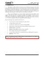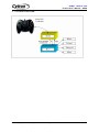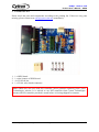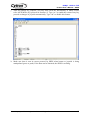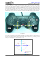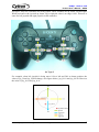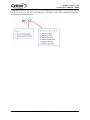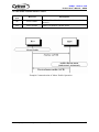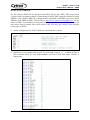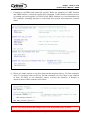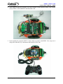
1
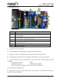
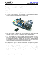
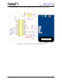
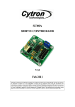
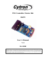
PS2 Controller Starter Kit
SKPS
User’s Manual
V1.0
Oct 2008
Information contained in this publication regarding device applications and the like is intended through suggestion only and may be
superseded by updates. It is your responsibility to ensure that your application meets with your specifications. No representation or warranty
is given and no liability is assumed by Cytron Technologies Incorporated with respect to the accuracy or use of such information or
infringement of patents or other intellectual property rights arising from such use or otherwise. Use of Cytron Technologies’s products as
critical components in life support systems is not authorized except with express written approval by Cytron Technologies. No licenses are
conveyed, implicitly or otherwise, under any intellectual property rights.
ROBOT . HEAD to TOE
Product User’s Manual – SKPS
Index
1. Introduction
1
2. System Overview
2
3. Packing List
3
4. Board Layout
4
5. Product Specification and Limitations
5
6. Hardware Interface
6
6.1 Microcontroller
6
6.2 Computer
8
6.3 PS2 Controller
14
7. Protocol
19
7.1 Non-ASCII Mode (Microcontroller)
19
7.1.1
Button and PS2 Controller Status
19
7.1.2
On Board Vibrator Motor Control
20
7.2 ASCII Mode (Computer)
21
7.2.1
Button and PS2 Controller Status
21
7.2.2
Read Key Functions
22
7.2.3
On Board Vibrator Motor Control
23
8. Getting Started
24
9. Warranty
27
Created by Cytron Technologies Sdn. Bhd. – All Rights Reserved
ROBOT . HEAD to TOE
Product User’s Manual – SKPS
1. INTRODUCTION
Play Station 2 (PS2) controller is relatively easy to obtain from any game store and it
offers good human manual input for control system. More and more developers are looking
into applying existing PS2 controller to control particular system. The major problem to
archive this is the socket for PS2 and the protocol to communicate with it. PS2 socket is very
unique and difficult to source. Besides, protocol to obtain the status (digital and analog) of
each button and analog stick on PS2 controller create headache to developer.
Thus, Cytron Technologies has designed a PS2 Controller Starter Kit, SKPS to offer
solution. This starter kit offers a compact yet reliable PS2 Controller Converter for user.
SKPS’s power and UART pin is compatible with SKKCA and SKXBee. A host is needed to
communicate with SKPS through UART. Reading Joy-stick button’s state will be as easy as
1, 2, 3. It offers a standard connector for Sony PS2 controller to plug-in.
It has been designed with capabilities and features of:
•
5V powered, low current consumption, less than 150mA.
•
1 standard PS2 controller socket.
•
Communicate with host microcontroller through UART.
•
Simple inquiry command and button status feedback for host to process.
•
Vibrator motor is controllable.
•
Wired or wireless PS2 controller is fully compatible.
•
PS2 Controller will only operate in analog mode.
•
A small LED as indicator for communication between SKPS and PS2 controller.
•
Dimension 7.4cm x 3.9cm
NOTE: Communication between SKPS and host is done through 5V TTL UART at
selectable baud rate (9600, 57600 or 115200)
Created by Cytron Technologies Sdn. Bhd. – All Rights Reserved
1
ROBOT . HEAD to TOE
Product User’s Manual – SKPS
2. SYSTEM OVERVIEW
Sony PS2
Controller
Created by Cytron Technologies Sdn. Bhd. – All Rights Reserved
2
ROBOT . HEAD to TOE
Product User’s Manual – SKPS
3. PACKING LIST
Please check the parts and components according to the packing list. If there are any parts
missing, please contact us at [email protected] immediately.
1.
2.
3.
4.
1 x SKPS board.
1 x mini jumper of SKPS board.
4 x 2510 iron pin.
1 x 2510 4 ways female connector.
Note: SKPS does not come with PS2 controller, please purchase separately from Cytron
Technologies website. It is advised to use PS2 controller from Cytron Technologies
because all PS2 controller provided is tested before it is being shipped to costumer.
Created by Cytron Technologies Sdn. Bhd. – All Rights Reserved
3
ROBOT . HEAD to TOE
Product User’s Manual – SKPS
4. BOARD LAYOUT
C
B
D
A
E
F
G
Label
A
B
C
D
E
F
G
Function
PS2 connector socket, please connect the PS2 controller here
5 ways header pin for external power and UART interface to
microcontroller.
4 ways 2510 header pin for external power and interface to PC or
microcontroller also (depends to user).
On board power indicator LED (Green)
On board indicator LED (Blue) indicators for check connection
with controller status.
On board reset button for SKPS.
Baud rate selector.
A – Connector for PS2 controller
B – 5 ways header pin for external power supply and UART interface.
C – Alternative 4 ways 2510 header pin for external power supply and UART.
D – On board power indicator LED. It should be ON if SKPS is powered by stable 5V.
E – On board indicator LED, it indicators the connection status between SKPS and PS2
controller.
No controller connected
: Blink
Controller connected
: On with 50% brightness
Controller connected (button pressed): On with 100% brightness
F – Reset button for SKPS board.
G – Baud rate selector. User may either choose 9600, 57600 or 115200 baud rate. Place the
jumper to select the baud rate.
Created by Cytron Technologies Sdn. Bhd. – All Rights Reserved
4
ROBOT . HEAD to TOE
Product User’s Manual – SKPS
5. PRODUCT SPECIFICATION AND LIMITATIONS
SKPS is designed to offer a compact and reliable PS2 Controller Converter for user. The
specifications are as listed below:
Label
Definition
Function
Power Input for
SKPS
External power source for SKPS, the typical voltage is
5V. Please ensure this 5V source is a stable supply.
Please do not use normal AC-DC adaptor to power it. It is
recommended to use linear regulator (7805) to provide
5V supply.
Ground or negative
Ground of power and signal.
RX
SKPS UART
Receive signal
This is SKPS’s receiver pin, it should be interfaced to 5V
logic UART, no divider is necessary. This is an input pin
to SKPS. It should be connected to microcontroller’s
transmitter pin.
TX
SKPS UART
Transmit signal
This is SKPS’s transmitter pin; it should be interfaced to
5V logic UART. This is an output pin from SKPS. It
should be connected to microcontroller’s receiver pin.
5V
GND
RESET SKPS Reset pin
Reset pin of SKPS. It should be connected to a push
button to Gnd, or NPN transistor.
Absolute Maximum Rating
Symbol
Parameter
5V
GND
RX
TX
RESET
Power source for SKPS
Operating voltage ground
Receiver pin of SKPS
Transmitter pin of SKPS
Reset pin of SKPS
Min
4.5
0
0
0
0
Max
5.5
0
5.5
5.5
5.5
Unit
V
V
V
V
V
NOTE: SKPS can only be powered by either by PC through 4 way 2510 connector or
external power (5V). The 5V must be a stable supply. Any ripple higher that 5.5V will
spoil the controller on SKPS and it is not replaceable.
Created by Cytron Technologies Sdn. Bhd. – All Rights Reserved
5
ROBOT . HEAD to TOE
Product User’s Manual – SKPS
6. HARDWARE INTERFACE
Generally, there are 2 methods of using SKPS. It has been designed for interface to
embedded system with 5V TTL (microcontroller) or connection to computer (normally for
functionality test).
6.1 Microcontroller
One of user’s main concerns when using SKPS is the interface with microcontroller.
a. To begin, user may connect 5V and Gnd of SKPS to microcontroller board. Header
socket can be used to connect SKPS to microcontroller board.
b. Once the 5V is supply to SKPS, the small green LED should light ON and Status LED
will blink. After PS2 is connected, it will stop blink and ON with half brightness.
c. As 2nd step, user might need to connect the RX and TX pin to microcontroller. Of course,
these two pins should be cross connected to microcontroller. In other words, RX should
be connected to microcontroller’s Transmitter pin (TxD), while TX should be connected
to microcontroller’s Receiver pin (RxD). No extra component is necessary between these
connections. For details connection, please refer to sample schematic.
d. If configuration of UART is completed, SKPS is ready for embedded development.
Sending and receiving data require software or firmware development on particular
microcontroller.
e. Finally, the RESET pin of SKPS. This is an optional pin for user as there is already a
reset button on SKPS. However, if user would like the microcontroller to reset SKPS
during run time, a transistor is required for interface between microcontroller and SKPS.
Please refer to following schematic for example of microcontroller interfacing with
SKPS.
Created by Cytron Technologies Sdn. Bhd. – All Rights Reserved
6
ROBOT . HEAD to TOE
Product User’s Manual – SKPS
f. Any microcontroller with UART peripheral can be used to interface with SKPS.
Example of connection to PIC16F877A microcontroller
Created by Cytron Technologies Sdn. Bhd. – All Rights Reserved
7
ROBOT . HEAD to TOE
Product User’s Manual – SKPS
6.2 Computer
SKPS can be connected to PC for functionality test. Another main concern during
development using SKPS is to check the functionality. Normally, user will need to develop
RS232 level shifter for communication to serial port. This generates extra work just to check
the functionality of SKPS. Furthermore, laptop and computer nowadays have phase-out the
serial port, USB have replaced it. With these reasons, an USB to UART converter have been
developed. Now, no extra work is required to check the functionally of on board SKPS.
Simply plug SKPS to UC00A and USB port of computer (PC or Laptop), install driver (1st
time) and there is an extra virtual COM port ready for SKPS. Checking functionality is
simple as 1, 2, 3.
a. Simply connect UC00A to SKPS, another end (A type) of UC00A to PC as shown in
following figure. User might need to connect the RX and TX pin toUC00A. Of course,
these two pins should be cross connected to UC00A. In other words, RX should be
connected to UC00A’s Transmitter pin (Tx), while TX should be connected to UC00A’s
Receiver pin (Rx). No extra component is necessary between these connections.
Wires in pin 1 and 2 are crossed for the second connector.
b. Please refer to document named “USB Driver Installation Guide” for driver installation.
Created by Cytron Technologies Sdn. Bhd. – All Rights Reserved
8
ROBOT . HEAD to TOE
Product User’s Manual – SKPS
c. After plug in the SKPS to computer and installation of driver, user is ready to test the
functionality of SKPS. Open the HyperTerminal. Enter a name and choose an icon for
connection as picture below then click OK.
d. Connect using USB Serial Port. If you are not sure which COM is it, please follow step
(e) to (g).
Created by Cytron Technologies Sdn. Bhd. – All Rights Reserved
9
ROBOT . HEAD to TOE
Product User’s Manual – SKPS
e. Go to Start, right click on My Computer and choose Properties.
Created by Cytron Technologies Sdn. Bhd. – All Rights Reserved
10
ROBOT . HEAD to TOE
Product User’s Manual – SKPS
f. At System Properties Table, choose Hardware and click on Device Manager. Device
Manager Table will show out.
g. At Device Manager Table, choose Ports (COM & LPT) and you can check your USB
Serial Port COM. The Serial Port COM is “COM20” in this case.
Created by Cytron Technologies Sdn. Bhd. – All Rights Reserved
11
ROBOT . HEAD to TOE
Product User’s Manual – SKPS
h. Set the Port Setting as picture below. Bits per second must be same with SKPS Baud Rate
and Flow control must be set to none. After finish setting, click Apply and then click OK.
i. Go to File and select Properties. ‘skps’ Properties table will show. Choose Setting tab and
click ASCII Setup tab. Click on Echo typed characters locally and then click OK.
Created by Cytron Technologies Sdn. Bhd. – All Rights Reserved
12
ROBOT . HEAD to TOE
Product User’s Manual – SKPS
j. After all settings are complete, user may now check the functionality of SKPS. Please
refer ASCII Mode (PC) protocol in Section 6.2. Type “ae” to enable the return of any key
pressed or changes of joystick automatically. Type “ad” to disable this feature.
k. Make sure data is sent in correct protocol by SKPS when button or joystick is being
manipulated (press or push). If the data can be obtained, the SKPS is working.
Created by Cytron Technologies Sdn. Bhd. – All Rights Reserved
13
ROBOT . HEAD to TOE
Product User’s Manual – SKPS
6.3 PS2 Controller
User may choose either wired or wireless PS2 Controller to be connected to SKPS. Figure
below shows the method to connect PS2 controller to SKPS board. There are many types of
PS controller in the market and the sensitivity for each type also different. User is advised to
use original PS2 controller. Cytron Technologies does not guarantee compatibility for all PS2
controllers.
(a) Wireless Connection
(b) Wired Connection
Created by Cytron Technologies Sdn. Bhd. – All Rights Reserved
14
ROBOT . HEAD to TOE
Product User’s Manual – SKPS
Figure below shows an example of PS2 controller which can be used for SKPS. There are 16
buttons that can be used as input button in PS2 controller.
L1, L2
R1, R2
Triangle
Up
Left
Right
Select
Start
Circle
Square
Down
Cross
Left
Joystick
Right
Joystick
Analog value of Left Joystick and Right Joystick can be read from SKPS. There are 2 axes
that can be read which are Type 1 and Type 2. It will be mentioned briefly after this. User can
use either Type 1 or Type 2.
Note: SKPS does not come with PS2 controller, please purchase separately from Cytron
Technologies website. It is advised to use PS2 controller from Cytron Technologies
because all PS2 controller provided is tested before it is being shipped to costumer.
Created by Cytron Technologies Sdn. Bhd. – All Rights Reserved
15
ROBOT . HEAD to TOE
Product User’s Manual – SKPS
For Type 1, there are 2 variables for each joystick which is axis X and axis Y. For example
user can move the joystick up, down for Y axis and left, right for X axis. For Y axis, when
users move the joystick up, the value will change from 128 to 0; when user move the joystick
down, the value will change from 128 to 255. For X axis, when users move the joystick right,
the value will change form 128 to 255; when user move the joystick left, the value will
change from 128 to 0. This axis is same for left joystick and right joystick on PS2 controller.
joy_ly
joy_ry
joy_lx
joy_rx
(a) Type 1
Let’s take an example on left joystick. Referring to the figure below, the left joystick is
moved a bit to the left and a bit to the up direction. So, the value of joy_lx and joy_ly will
changed, as in the figure joy_lx=70 and joy_ly=92.
Created by Cytron Technologies Sdn. Bhd. – All Rights Reserved
16
ROBOT . HEAD to TOE
Product User’s Manual – SKPS
For type 2, they are 4 variables for each joystick. The 4 variables are up, down, left and right.
When users move the joystick up, down, left or right the value is at range 0-100. This axis is
same for left joystick and right joystick on PS controller.
(b) Type 2
For example, when left joystick is being move 10% to left and 50% to down position, the
value of joy_ll and joy_ld will change, as in figure below, joy_ll=10 and joy_ld=50. However
the value of joy_lu=0 and joy_lr=0.
Created by Cytron Technologies Sdn. Bhd. – All Rights Reserved
17
ROBOT . HEAD to TOE
Product User’s Manual – SKPS
Please take note that the joy_lx, joy_ly, joy_rx and joy_ry is for type 1 axis; joy_lu, joy_ld,
joy_ll, joy_lr, joy_ru, joy_rd, joy_rl and joy_rr is for type 2 axis. This variable is being name
according to a standard format.
Created by Cytron Technologies Sdn. Bhd. – All Rights Reserved
18
ROBOT . HEAD to TOE
Product User’s Manual – SKPS
7. PROTOCOL
7.1 Non-ASCII Mode (Microcontroller)
7.1.1 Button and PS2 Controller Status
Send (decimal)
0
1
2
3
4
5
6
7
8
9
10
11
12
13
14
15
16
17
18
19
20
21
22
23
24
25
26
27
28
Button of Controller
select button
left joystick center button
right joystick center
button
start button
up button
right button
down button
left button
L2 button
R2 button
L1 button
R1 button
triangle button
circle button
cross button
square button
left joystick x-axis
left joystick y-axis
right joystick x-axis
right joystick y-axis
left joystick up value
left joystick down value
left joystick left value
left joystick right value
right joystick up value
right joystick down value
right joystick left value
right joystick right value
Description
SKPS will return the status of
corresponding button when the particular
decimal value is received
0 if the button is pressed
1 if button is not pressed
Example:
If microcontroller sent 10 (decimal), SKPS
will check L1 button status on PS2
Controller. SKPS will return
0 if L1 button is pressed or
1 if L1 is not pressed.
SKPS will return the particular value of
corresponding joystick in the selected axis
Example :
If microcontroller sent 20 (decimal), SKPS
will read and return the value of left
joystick up.
SKPS will read controller status
1 is return if controller is detected
Created by Cytron Technologies Sdn. Bhd. – All Rights Reserved
19
ROBOT . HEAD to TOE
Product User’s Manual – SKPS
7.1.2 On board Vibrator Motor Control
send 1st
byte
(decimal)
send 2nd
byte
(decimal)
29
motor1 value
30
motor2 value big vibrator placed on left side
Controller
small vibrator placed on right
side
Description
motor1 = 1 or 0 (on or off)
motor2 = 0 -> 255
(adjustable vibration)
(a) Example Communication of Circle Button Operation
(b) Example Communication of Left Joystick Right Value Operation
Created by Cytron Technologies Sdn. Bhd. – All Rights Reserved
20
ROBOT . HEAD to TOE
Product User’s Manual – SKPS
7.2 ASCII Mode (PC)
7.2.1 Button and PS2 Controller Status
Send 2
byte
up
Button of Controller
up button
dw
down button
lf
left button
rg
right button
tr
triangle button
cr
circle button
sq
ci
st
cross button
square button
start button
se
jl
jr
l1
L2 button
r1
R1 button
r2
R2 button
lx
left joystick x-axis
ly
left joystick y-axis
rx
right joystick x-axis
ry
right joystick y-axis
lu
left joystick up value
ld
left joystick down value
ll
left joystick left value
lr
left joystick right value
ru
right joystick up value
rd
right joystick down value
rl
right joystick left value
rr
right joystick right value
unknown
SKPS will return the status of corresponding
button when the particular ASCII value is
received
‘0’ if the button is pressed
‘1’ if button is not pressed
Example:
If microcontroller sent ‘r2’ (ASCII), SKPS will
select button
check R2 button status on PS2 Controller. SKPS
left joystick center button will return
‘0’ if R2 button is pressed or
right joystick center button ‘1’ if R2 is not pressed.
[“Enter” after every result]
L1 button
l2
cs
Description
SKPS will return the particular value of
corresponding joystick in the selected axis
(3 byte, in ASCII).
Example: ‘235’or ‘029’.
[“Enter” after every result]
SKPS will return the particular value of
corresponding joystick in the selected axis
(3 byte, in ASCII).
Example: ‘039’or ‘027’.
[“Enter” after every result]
SKPS will read controller status
‘1’ is return if controller is detected
SKPS will return ‘x’ if unknown data is sent.
Created by Cytron Technologies Sdn. Bhd. – All Rights Reserved
21
ROBOT . HEAD to TOE
Product User’s Manual – SKPS
7.2.2 Read Key Functions
Send 2
byte
Received
Controller
rk
all key status
any press
button/joystick value
ae
auto read
enable
any press
button/joystick value
ad
auto read
disable
any press
button/joystick value
Description
SKPS will return pressed key and
changed joystick value once.
[“Enter” after result]
SKPS will enable return pressed
key and changed joystick
automatically.
[“Enter” after result]
SKPS will disable return pressed
key and changed joystick
automatically.
[“Enter” after result]
Example communication of Auto Read Enable Operation
Created by Cytron Technologies Sdn. Bhd. – All Rights Reserved
22
ROBOT . HEAD to TOE
Product User’s Manual – SKPS
7.2.3 On board Vibrator Motor Control
Send 2
byte
Received
me
motor enable
md
motor disable
Description
SKPS will enable vibrator motor (both motor1 and
motor2)
SKPS will disable vibrator motor
Example Communication of Motor Enable Operation.
Created by Cytron Technologies Sdn. Bhd. – All Rights Reserved
23
ROBOT . HEAD to TOE
Product User’s Manual – SKPS
8. GETTING STARTED
For this section, SKPS will be interfaced with PR23. Please refer PR23, DIY project from
Cytron website for details example of interfacing to SKPS. PR23 shows the method of using
SKXBee, since SKPS UART pin is designed to be compatible to SKXBee, user may replace
SKXBee with SKPS on PR23. Please refer to http://www.cytron.com.my/PR23.asp for the
details of PR23. For method of writing most simple program to use with SKPS, please refer
steps below and for sample full version source code, user may get it from Cytron Website
(same page as SKPS).
a. Set the configuration for UART. Make sure the baud rate is correct.
b. Definition of every button and joystick. For following example, “p_” is added in front of
PS2 controller label for easy understandable and avoid crash with other variable or
instructions.
Created by Cytron Technologies Sdn. Bhd. – All Rights Reserved
24
ROBOT . HEAD to TOE
Product User’s Manual – SKPS
c. Function to read SKPS and control the joystick. Below are examples of UART function
and SKPS function. Comments explain each command. UART function controls process
of sending and receiving data via UART while SKPS function is to read information on
PS2 controller including function to read button and joystick and control the vibrator
motor.
d. Below are sample on how to use those function that mentioned above. For first command,
when L1 is pressed, buzzer will beep. Second command is to test if there is any obstacle
in front. For PR23 we use ultrasonic sensors to detect the obstacles. If obstacle is
detected, motor in PS2 controller will vibrate.
NOTE: User may download this sample source code from product page of SKPS.
Created by Cytron Technologies Sdn. Bhd. – All Rights Reserved
25
ROBOT . HEAD to TOE
Product User’s Manual – SKPS
e. After finish writing the program, user may compile it and load the source code. Please
refer to PR23 on the method to download the code.
f. Upon loading the program, PR23 is now ready to operate with SKPS. User may test it
using PS2 controller, try each button and function. Have fun!
Created by Cytron Technologies Sdn. Bhd. – All Rights Reserved
26
ROBOT . HEAD to TOE
Product User’s Manual – SKPS
9. WARRANTY
¾
¾
¾
¾
Product warranty is valid for 6 months.
Warranty only applies to manufacturing defect.
Damage caused by mis-use is not covered under warranty.
Warranty does not cover freight cost for both ways.
Prepared by
Cytron Technologies Sdn. Bhd.
19, Jalan Kebudayaan 1A,
Taman Universiti,
81300 Skudai,
Johor, Malaysia.
Tel:
Fax:
+607-521 3178
+607-521 1861
URL: www.cytron.com.my
Email: [email protected]
[email protected]
Created by Cytron Technologies Sdn. Bhd. – All Rights Reserved
27