1
PSZ 19:16 (Pind. 1/07)
UNIVERSITI TEKNOLOGI MALAYSIA
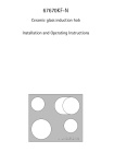
DECLARATION OF THESIS / UNDERGRADUATE PROJECT PAPER AND COPYRIGHT
Author’s full name :
HARUN AMINURASYID BIN ABU BAKAR
Date of birth
:
16 MARCH 1990
Title
:
ANDROID SMARTPHONE CONTROLLER MOBILE
ROBOT
Academic Session :
2012/2013
I declare that this thesis is classified as :
CONFIDENTIAL
(Contains confidential information under the Official Secret
Act 1972)*
RESTRICTED
(Contains restricted information as specified by the
organization where research was done)*
OPEN ACCESS
I agree that my thesis to be published as online open access
(full text)
I acknowledged that Universiti Teknologi Malaysia reserves the right as follows:
1.
2.
3.
The thesis is the property of Universiti Teknologi Malaysia.
The Library of Universiti Teknologi Malaysia has the right to make copies for the purpose
of research only.
The Library has the right to make copies of the thesis for academic exchange.
Certified by :
SIGNATURE
900316-01-6249
(NEW IC NO. /PASSPORT NO.)
Date : 24 JUNE 2013
NOTES :
*
SIGNATURE OF SUPERVISOR
PROF DR SHAMSUDIN BIN HJ MOHD AMIN
NAME OF SUPERVISOR
Date : 24 JUNE 2013
If the thesis is CONFIDENTAL or RESTRICTED, please attach with the letter from
the organization with period and reasons for confidentiality or restriction.
ii
“I hereby declare that I have read this thesis and in my opinion this thesis is
Sufficient in terms of scope and quality for the award of the degree of
Bachelor of Engineering (Electrical – mechatronics)”
Signature
: ………………………
Name of Supervisor : PROF. DR SHAMSUDIN B HJ
MOHD AMIN
Date
: 24 JUNE 2013
ANDROID SMARTPHONE CONTROLLER MOBILE ROBOT
HARUN AMINURASYID BIN ABU BAKAR
A thesis submitted in partial fulfilment
of the requirement for the award of the degree of
Bachelor of Engineering (Electrical – Mechatronics)
Faculty of Electrical Engineering
Universiti Teknologi Malaysia
JUNE 2013
ii
I declare that this thesis entitle “Android Smartphone Controller Mobile Robot” is
the result of my own research except as cited in the reference. The thesis has not
been accepted for any degree and it not concurrently submitted in the candidature of
any other degree.
Signature
: ………………………
Name
: HARUN AMINURASYID BIN
ABU BAKAR
Date
: 24 JUNE 2013
iii
Dedicated, in thankful appreciation for support, encouragement and inspired me
throughout my journey of education to my beloved mother, brother, sister and my
friends that has always been there for me.
iv
ACKNOWLEDGEMENT
First of all, I am grateful to Allah S.W.T. for giving me the strength and good
health to complete this project successfully. Next, special gratitude to my supervisor,
PROF DR SHAMSUDIN HJ MOHD AMIN for his guidance, encouragement and
ideas to me from start until finished the project.
I would also like to thank my family for their support and encouragement for
the rest of my life. My special thanks to my friends, especially for my classmates for
their guidance and teamwork during my learning process for four years in UTM.
Last but not least, to those who helped me directly or indirectly, I would like
to say thank you very much and may Allah bless and repay you well, Insha’Allah.
v
ABSTRACT
Smart phones have become very popular in recent years. There are a lot of
benefits to having a smart phone, far more than most people realize. The truth is that
few people actually get the full benefit out of their smart phone and use it primarily
as a regular phone with a few extra features, there are so many other things that a
smart phone can do. This gadget can do many task and activities as there are many
type of sensors were provided inside the smartphones. The robot can be controlled
more easily with smartphone since it is more flexible and has an extra function. We
could see in the future, the engineers and operators will used their own smartphone to
control the robot in industry. This project investigates the use of smartphone to
control mobile robot via Bluetooth wireless. The mobile robot is build and was
controlled by wireless with using the smartphone. Microchip PIC16F877A is used
because it more powerful rather than other and it has a more pin that can do more
function and task. The microchip will be programming by using MPLAB since it is
commonly used and easier to program. The mobile robot and the smartphone are
connected via Bluetooth by using SKXBEE devices. The smartphone is using an
Android application. Android is an operating system for phone that widely used by
the people around the world. The Android application for this project can be used by
other Android smartphones and users to control their own mobile robot. This project
shows the smartphone as a modern technology can be used to reduce the cost to
replace the others mobile robot controller.
vi
ABSTRAK
Sejak akhir-akhir ini telefon pintar menjadi semakin diminati ramai. Terdapat
banyak faedah yang boleh diperolehi dengan memiliki telefon pintar. Ramai orang
boleh mendapat manfaat sepenuhnya daripada telefon pintar mereka selain
menggunakannya sebagai telefon biasa, dengan beberapa ciri-ciri tambahan terdapat
banyak perkara-perkara lain yang telefon pintar boleh lakukan. Alat ini boleh
melakukan tugas dan aktiviti yang banyak dengan pelbagai jeenis sensor yang telah
disediakan di dalam telefon pintar. Robot boleh dikawal dengan lebih mudah dengan
telefon pintar kerana lebih fleksibel dan mempunyai fungsi tambahan. Pada masa
akan datang, jurutera dan pengendali akan menggunakan telefon pintar mereka
sendiri untuk mengawal robot dalam industri. Projek ini mengkaji penggunaan
telefon pintar untuk mengawal robot mudah alih melalui wayarles Bluetooth. Robot
mudah alih membina dan dikawal oleh wayarles dengan menggunakan telefon pintar.
Microchip PIC16F877A digunakan kerana ia lebih sesuai dan mempunyai pin yang
lebih yang boleh melakukan fungsi dan tugas yang lebih banyak. Mikrocip
pengaturcaraan akan menggunakan MPLAB kerana sesuai digunakan dan mudah
untuk program. robot mudah alih dan telefon pintar yang menggunakan aplikasi
Android dihubungkan melalui Bluetooth dengan menggunakan peranti SKXBEE.
Android adalah sistem operasi untuk telefon yang digunakan secara meluas di
seluruh dunia. Aplikasi Android untuk projek ini boleh digunakan oleh telefon pintar
Android yang lain dan pengguna boleh mengawal robot mudah alih mereka sendiri.
Projek ini membuktikan telefon pintar sebagai teknologi moden boleh digunakan
untuk mengurangkan kos untuk menggantikan pengawal robot mudah alih yang lain.
vii
TABLE OF CONTENTS
CHAPTER
TITLE
DECLARATION
DEDICATION
ACKNOWLEDGEMENT
ABSTRACT
ABSTRAK
TABLE OF CONTENT
LIST OF TABLES
LIST OF FIGURES
LIST OF ABBREVIATIONS
LIST OF APPEDINCES
PAGE
ii
iii
iv
v
vi
vii
ix
x
xi
xii
1
INTRODUCTION
1.1 Project Background
1.2 Objectives
1.3 Project Scope
1.4 Problem Statement
1
1
3
4
4
2
LITERATURE REVIEW
2.1 Introduction
2.2 Computer Controlled Mobile Robot
2.3 Android E-NOSE
2.4 Remote Home Surveillance Using Android
Platform
2.5 Summary of Chapter
5
5
6
7
10
METHODOLOGY
3.1 Introduction
3.2 Project Planning
11
11
11
3
9
viii
4
5
3.3 Hardware Part
3.3.1 Mobile Robot
3.3.2 Voltage Regulator
3.3.3 Power Source
3.3.4 Microcontroller
3.3.5 Bluetooth Module
3.3.6 Interface LCD
3.3.7 Servo Motor
3.3.8 Printed Circuit Board
3.4 Software Part
3.4.1 Microcontroller Programming
3.4.2 Android Software
3.4.3 App Inventor
3.5 Flowchart
3.6 Testing And Troubleshooting
3.7 Summary of Chapter
12
13
14
15
16
18
20
21
22
23
24
26
26
29
31
32
RESULT AND DISCUSSIONS
4.1 Introduction
4.2 Modified Mobile Robot
4.3 Android Application Mobile Robot Controller
4.4 The Movement of Mobile Robot
4.5 Discussions
4.6 Summary of Chapter
33
33
34
36
38
39
CONCLUSION AND RECOMENDATIONS
5.1 Introduction
5.2 Conclusions
5.3 Recommendations
40
40
40
41
REFERENCES
APPENDIX A
APPENDIX B
42
44
46
ix
LIST OF TABLES
TABLE
NO.
3.1
4.1
4.2
TITLE
LCD Module Pin Description
The result of using keypad
The result of using accelerometer sensors
PAGE
20
36
37
x
LIST OF FIGURES
TABLE
NO.
2.1
2.2
2.3
2.4
2.5
3.1
3.2
3.3
3.4
3.5
3.6
3.7
3.8
3.9
3.10
3.11
3.12
3.13
3.14
3.15
3.16
3.17
3.18
4.1
4.2
4.3
4.4
TITLE
Two wheeled differential drive mobile robot
Layout of the GUI
User interface of Android E-Nose application using IOIO
board
User interface of the Android Application E-NOSE
application
Remote Home Surveillance in Android phone
Flowchart of project planning
Cytron Multifunction Mobile Robot
Voltage regulator LM7805
The circuit of voltage regulator LM7805
Lipo battery 11.1V
pin diagram of PIC16F877A
Circuit Connection of PIC16F877A
Circuit Connection of LCD
Servo Motor C36R Cytron
PCB of mobile robot
MPLAB Window Interfaces
Cytron USB Programmer/In Serial Circuit Debugger (ICSP)
PIC Programmer interface window
App Inventor for Android
Designer of Android Application
Block Editors of Android Application
Flowchart of Android Application
Flow chart of PIC microcontroller
Mobile robot with Bluetooth communication
Android Application Mobile Robot Controller
Interface of Android Application
The mobile robot controlled by smartphone
PAGE
6
7
8
8
9
12
13
14
14
16
17
17
21
21
22
24
25
25
27
28
28
29
30
34
35
35
37
xi
LIST OF ABBREVIATIONS
PIC
-
Programmable Intelligent Computer
PCB
-
Printed Circuit Board
GUI
-
Graphical User Interface
SDK
-
Software Development Kit
LED
-
Pulse Width Modulation
UART
-
Universal Asynchronous Receiver Transmitter
TX
-
Transmitter
RX
-
Receiver
ICSP
-
In-Circuit Serial Programming
OS
-
Operating System
PS2
-
Play Station 2
LiPo
-
Lithium Polymer
AC
-
Alternate Current
DC
-
Direct Current
LED
-
Light Emitting Diode
xii
LIST OF APPEDINCES
APPENDIX
A
B
TITLE
Gant Chart
Source Code of PIC Microcontroller
PAGE
44
46
1
CHAPTER 1
INTRODUCTION
1.1
Project Background
Nowadays, robot play an important role in industrial area since the
capabilities to doing something or job that are impossible due to limited abilities of
human. Robot are able to do the repetitive work with constant performance, do a
dangerous thing that can risk to human and make a product faster with less rest time.
Besides, robot is less cost when compare with worker salary. Refer to the
International Standard Organization’s definition of an industrial robot, mobile robot
can be define as;
“A mobile robot is an autonomous system capable of traversing a terrain with
natural or artificial obstacles. Its chassis is equipped with wheels/tacks or legs and
possibly a manipulator setup mounted on the chassis for handling of work pieces,
tools or special devices. Various preplanned operations are executed based on a
preprogrammed navigation strategy taking into account the current status of the
environment” [1].
2
In other words, any intelligent machine which moves with respect to
environment within limited human interaction (autonomously) called “Mobile
robot”.
According to Furat Barlas [2],”Mobile robots can be used in several
applications. Dangerous area operations (Nuclear plants), planetary exploration and
pipe investigation, extreme temperature and narrow field investigations (pyramid
exploration robots). Moreover, floor cleaning robots and servant robots are common
examples for indoor use. It is not a dream that, in near future robots will be a part of
our daily life.”
The smartphone is defined as a mobile phone that has an open operating
system where user can install new applications that can access directly the services of
the phone. Smartphone existence because the user want the flexibility in term of
mobile format as they used to with computer. The technical development in
semiconductor industry has enabled the development of smart phones providing
adequate computational capabilities and amount of memory in small and power
efficient chips and this combination is desirable to more and more customers.
The industrial applications are mostly human interfaces of machine to
machine communication which suitable with smartphone as it will more easily. The
currently mostly used industrial applications can be divided as
-
Monitoring
-
Reporting
-
Viewing of documents etc.
-
Position and location based applications
Two-way data transfers can be used to send sensor information, video or
other information for processing to other places where that information can be for
example compared to databases and this analysis result can be send back to the smart
3
phone user. This similar information analysis based on database information can be
done also using smart phones own processing and storage capabilities but of course
in smaller scale [3].
Android operating system is an open source framework designed for Android
devices such as smartphones and tablets. It is a comprehensive platform that features
a Linux based operating system stack for managing devices, memory and processes.
Google created the framework and made it to be available to Java Programmers
through a Software Development Kit (SDK) that is known as Android SDK. The
Android SDK provides libraries needed to interface with the hardware at a high level
make Android applications [4].
Anyone can develop their application for free and install in their mobile
phone. It has open marketplace which is called Google Play where developers can
distribute, share and sell their application.
1.2
Objectives
The main objective of this project is to design and modified a communication
mobile robot that can be controlled via wireless by smartphone through Bluetooth.
Secondary objective is to developed Android software by using App Inventor for
Android
4
1.3
Project Scope
This project involves both hardware and software. Hardware is mobile robot
need to modify and software has two main parts which is programming the mobile
robot and programming the Android application. The scope of the project involves:-
1. A mobile robot with PIC microcontroller
2. Android smartphone to install the Android application as a controller of
mobile robot
1.4
Problem Statement
Nowadays, with the advancement of information technology, people tend to
carry their mobile gadgets wherever they go, particularly the smartphones, as it is
seen to become very important in their daily activities. As in near future robots will
be a part of our daily life, it is better to build a program to control the robot with
latest technology such smartphone since it user friendly and will be more easier carry
the program anywhere.
Cost of the controller of robot is another subject. Since Android is a free
application developer, it will cut the cost and replace robot controller such as PS2
controller and computer.
5
CHAPTER 2
LITERATURE REVIEW
2.1 Introduction
There are many relevant and similar projects that can be search around the
world. In this chapter, a number of previous research projects of mobile robot are
reviewed. The chapter also discusses on Android devices and briefly summarizes the
application of Android devices in various fields. The research projects provide
information such as the theories, techniques and designed applied.
For this chapter, there are 3 references are chosen as they are related to the
current project which can be review as guideline and information to finish this
project.
6
2.2
Computer Controlled Mobile Robot
This project was developed by UTM student, Mohd Bazli Bin Mohd Mokhar.
In this project, Bazli used Graphical User Interface (GUI) as interface to mobile
robot. The command given in order to control direction, speed, distance and degree
of turn of the mobile robot by computer via wireless.
According to Bazli [5], “In this project, two wheel differential drive mobile
robot is built. By using the computer, the mobile robot is control by wireless. Mobile
robot control using computer is very common project in final year project. However,
based from the previous projects, not all variable of mobile robot control was
controlled. The common variable based on previous projects is to control the
direction of the mobile robot. There are a little researches or projects that control
other variable in mobile robot control such as distance or speed. So, in this project,
direction, speed, distance and degree of turn of the mobile robot are control at the
same time. In addition, a Graphical User Interface (GUI) is developed for controlling
of mobile robot. Wireless communication between host computer and robot is
established using Bluetooth Module.”
Figure 2.1 Two wheeled differential drive mobile robot
7
Figure 2.2: Layout of the GUI
2.3
Android E-NOSE
In 2012, a project named Android E-NOSE done by UTM student. This
project used Android as the interface for E-NOSE application. The result of the data
and type of gases detected by E-NOSE will be shown on the Android mobile phone
screen.
According to Safwan [6], “The paper presents the design of an Android
device as a platform to display data from an electronic nose. The Android E-Nose is
developed using two different microcontrollers (Microchip DM240415 PIC24F
Accessory Development Starter Kit for Android™ and IOIO for Android) which can
be used separately to work with any (suitable) Android devices (smartphones or
tablets). The proposed device is designed to be small, less expensive, portable and
user friendly. The proposed portable Android E-Nose should be able to measure and
discriminate between different types of gases with a user-friendly interface.”
8
Figure 2.3: User interface of Android E-Nose application using IOIO board
Figure 2.4: User interface of the Android E-Nose application
9
2.4
Remote Home Surveillance Using Android Platform Phone Through
TCP/IP
This project also is using Android operating system of mobile phone for their
interface with the application remote home surveillance. This application shows live
view of their home on Android phone by connected it with Internet. The people can
check the condition of their home anywhere as long they have an Internet. User also
can setting a password for this application for safety only user can access to this
application.
According to Muhammad Affandy [7], “This project is concerned for this
kind of situation and creating this program is easy by just purchasing an IP camera
and the rich features of open source Android–platform phone. Just by using open
source tools like JSF programming and Android client programming, one can create
a software with ease with only sufficient knowledge about networking.”
Figure 2.5: Remote Home Surveillance in Android phone
10
2.5
Summary of Chapter
These 3 projects and research have a part that related to this project which
some of component and source code can be applied to improve the project. First
project can be guidelines to design a mobile robot and develop communication
Bluetooth wireless. Meanwhile, others 2 projects can be as references to develop
Android application and connected it with Bluetooth wireless devices.
11
CHAPTER 3
METHODOLOGY
3.1
Introduction
This chapter will discuss about the methodology approach for solving the
problem as mention on problem statement in the previous chapter. This chapter consists
of work on planning, system design, hardware, software development and testing to
make sure the flow of project development run smoothly and systematically.
3.2
Project Planning
Flowchart for project planning was done in order to complete this project.
The first step is to propose this idea to supervisor. The second step is to do some
research and literature review regarding this project which is based on the theory and
application. Next, the mobile robot and wireless module were purchased and build as
involved in designing the hardware part. The fourth step is to programming PIC of
12
mobile robot. After that, Android application will developed as mobile robot control.
The sixth step is the integration of both software and hardware. The mobile robot
will be testing by a simple command. As the communication between mobile robot
and Android smartphone is establish, the programming to will be continue to
increase the capabilities to control by smartphone. The last step is testing and
troubleshooting of the software and the mobile robot. Figure 3.1 shows the flowchart
of project planning.
Idea and proposal
Research and Literature Review
Designing the hardware
Programming PIC microcontroller
Developed Android application
Hardware and software integration
Testing and troubleshooting
Figure 3.1: Flowchart of project planning
3.3
Hardware Part
The hardware parts consist of electric component and devices. This part also
included with the mobile robot that will be used and modified for this project.
13
3.3.1
Mobile Robot
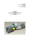
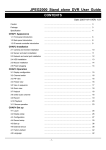
Figure 3.2: Cytron Multifunction Mobile Robot
Cytron DIY PIC microcontroller based project, PR23 (model) is designed for
user to start develop mobile robot. The sample code provided showing few capability
such as:
1. Line following
2. Obstacles detection using Ultrasonic Sensor
3. Obstacles detection using Analog Sensor
4. Control using XBee module
5. Control using PS2 controller
PR23 is an open source microcontroller Do It Yourself kit. This PIC
microcontroller based project perfectly designed for user to start develop smart
robot. It is a line following robot with optional add on gadget and capable of line
following, distance measure, and control wirelessly. It also provides LCD (2X16
Character) and buzzer for user to indicate the condition or status of the robot that
useful for debugging and testing.
This multifunction mobile robot is modified and designed to be able control
its movement by Bluetooth wireless which connected with smartphone. The other
function such as line following is removes because it is not appropriate with this
project.
14
3.3.2
Voltage Regulator
The PIC microcontroller and this circuit required 5V voltage input to operate
the circuit, thus this project are converts the higher input voltage to 5V by using
voltage regulator LM7805. Figure 3.3 below shows circuit of voltage regulator
LM7805.
Figure 3.3: Voltage regulator LM7805
Figure 3.4: The circuit of voltage regulator LM7805
This circuit have 2 diferent type of power supply which can be used either
AC to DC adaptor or 9V-12V battery to power up the circuit. Higher input voltage
will produce more heat at LM7805 voltage regulator. Typical voltage is 12V.
15
Anyhow, LM7805 will still generate some heat at 12V. Diode D2 is use to protect
the circuit from wrong polarity supply. Capacitor C3 and C10 is use to stabilize the
voltage at the input side of the LM7805 voltage regulator, while the Capacitor C8
and C11 is use to stabilize the voltage at the output side of the LM7805 voltage
supply. LED is a green LED to indicate the power status of the circuit. R10 is resistor
to protect LED from over current that will burn the LED.
3.3.3
Power Source
Power supply is very important for each electronic circuit and devices inside
the mobile robot. Without the properly regulated power supply it can affect the
circuit and cause the robot malfunction. If the power supply for the circuit of mobile
robot is less than required, the circuit will might not have enough energy and cause
the problem such as LCD not displayed, LED not turn light and the microcontroller
not receive the data from Bluetooth module. But if the exceeded current or voltage is
supply, the circuit will damaged and malfunction as the microcontroller will burn. In
this project, 5V is used to supply into microcontroller and other devices. The circuit
is consisting of voltage regulator 5V to get the energy required. Meanwhile for servo
motor is using 6V with separated voltage regulator 6V. For Bluetooth module
BlueBee it should operate at 3.3V, however with the SKXBEE-Board it converts the
voltage input 5V from PIC microcontroller to voltage input 3.3V. SKXBEE-Board
will be equipped with Bluetooth module.
For all supply voltage of the mobile robot, the power source will be 11.1V
Lithium Polymer (Lipo) Rechargeable Battery. This power supply should be enough
for both microcontroller and servo motor of the mobile robot. The advantage of this
battery beside rechargeable is small-size and lightweight when compare with other
type of battery with the same capability. Figure 3.5 below show 11.1V Lipo battery.
16
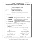
Figure 3.5: Lipo battery 11.1V
Specification:
Ordinary Voltage: 11.1V
Fully-charge Voltage: 12.6V
Capacity: 2200mAh
Discharge rate: 30C
Able to use for most of the 12V controllers, motors or any other appliances
Must charge with designated LiPo Battery Charger
3.3.4
Microcontroller
Microcontroller 16F877A is chosen for this project. Below is some of the
feature of this microcontroller:
• 256 bytes of EEPROM data memory
• self-programming
• 2 Comparators
• 8 channels of 10-bit Analog-to-Digital (A/D) converter
• 2 capture/compare/PWM functions
• synchronous serial port can be configured as either 3-wire Serial Peripheral
Interface (SPI™) or the 2-wire Inter-Integrated Circuit (I²C™) bus
• Universal Asynchronous Receiver Transmitter (UART)
17
This powerful (200 nanosecond instruction execution) yet easy-to-program
(only 35 single word instructions) CMOS FLASH-based 8-bit microcontroller packs
Microchip's powerful PIC® architecture into an 40- or 44-pin package and is
upwards compatible with the PIC16C5X, PIC12CXXX and PIC16C7X devices. It
has many ports for input and output that suitable for multifunction mobile robot.
Other than that, pin for receiving and transmitting data also included which is used
for this project.
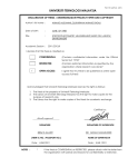
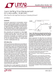
Figure 3.6: Pin diagram of PIC16F877A
Figure 3.7: Circuit Connection of PIC16F877A
Microcontroller PIC16F877A is a 40 pins microcontroller which has five I/O
ports. PIC16F877A is chosen to be used as the main processing unit for the mobile
robot because it has high enough performance but with cheaper price, which is only
18
cost about RM20. Besides, this microcontroller has 2 PWM modules with 10 bits
resolutions. The transmitter pin (TX) RC6 and receiver pin (RX) RC7 is used to
communicate with wireless connection with smartphone by using Bluetooth Module.
Four pins of the PIC16F877A are used to control the direction of two servo motors
which is RC0, RC3, RC4 and RC5. Beside, an external crystal of 20Mhz is
connected to the PIC18F4550 at pin 13 and 14 as shown in Figure to establish
oscillation. For 20Mhz crystal, two 30pF capacitors are used for oscillator stability
purpose.
3.3.5
Bluetooth Module
For this project, Bluetooth module BlueBee from Cytron Technologies is
used. The main criteria Bluetooth wireless is chosen because the other wireless
cannot be used with smartphone such as XBEE wireless because both devices have a
different type of wireless and the XBEE wireless only can be connected between two
XBEE modules. Since smartphone cannot connect directly with XBEE module,
Bluetooth wireless is the efficient way to connect the smartphone with other devices.
It also can reduce the cost as is only needed one Bluetooth module and its price is
cheaper than XBEE module.
This BlueBee wireless module is new product from Cytron Technologies,
utilizing the XBee form factor, BlueBee is compatible with XBee adapter such
as SKXBee (without module), XBee breakout board and Arduino-XBee shield.
Though the form factor (pin out) is compatible with XBee module, BlueBee uses
Bluetooth Technologies. It has compact size, the pinout is compatible with XBee
which is suitable for all kinds of microcontroller systems that have 3.3V power out,
the module can use the AT commands to set baud rate.
The BlueBee module comes with an on-board antenna, the antenna provides
better signal quality. It acts like a transparent serial port, which works with a variety
of Bluetooth adapter and Bluetooth phone. It only provide SPP (Serial Port Profile)
19
where it becomes serial COM port once it establish connection with master
Bluetooth.
BlueBee module's baudrate can modified using XBEE adapter. By using
SKXBEE-BOARD or XBEE Arduino controller receives the base plug, enabling
Bluetooth wireless control. Current version BlueBee Bluetooth module is only
a slave module. Communication among two BlueBee is not possible. The connection
must be initiated from Bluetooth Dongle (Laptop or computer), or handphone that
have Bluetooth.
Specifications:
Bluetooth chip: CSR BC04 Chipset
Bluetooth protocol: Bluetooth Specification v2.0 + EDR
Operating frequency: 2.4 ~ 2.48GHz unlicensed ISM band
Modulation: GFSK (Gaussian Frequency Shift Keying)
Transmit Power: ≤ 4dBm, Class 2
Transmission distance: 20 ~ 30m in free space
Sensitivity: ≤-84dBm at 0.1% BER
Transfer rate: Asynchronous: 2.1Mbps (Max) / 160 kbps; Synchronous:
1Mbps/1Mbps
Safety features: Authentication and encryption
Support profiles: Bluetooth serial port
Serial port settings: 1200 ~ 1382400 / N / 8 / 1
Baud rate default: 9600 bps(Serial Port Profile, transparent mode)
Baud rate default: 38400 bps in AT mode.
Input Voltage: +3.3 DC/50mA
Operating temperature: -20 ℃ ~ +55 ℃
Module Size: 32 × 24 × 9mm
20
3.3.6
Interface LCD
Liquid crystal display (LCD) 2X16 character is using for the mobile robot.
Table 3.1 shows connection pin and function of each pin is shown:
Pin Name Pin function
1
VSS
Ground
2
VCC
Positive Supply for LCD
3
VEE
4
RS
5
6
7
8
9
10
11
12
13
14
15
16
R/W
E
DB0
DB0
DB0
DB0
DB0
DB0
DB0
DB0
LED+
LED-
Brightness Adjust
Select register, select instruction
or data register
Select read or write
Start data read or write
Data bus pin
Data bus pin
Data bus pin
Data bus pin
Data bus pin
Data bus pin
Data bus pin
Data bus pin
Backlight positive input
Backlight negative input
Connection
GND
5V
Connected to a
preset to adjust
brightness
RB7
GND
RB6
RD0
RD0
RD0
RD0
RD0
RD0
RD0
RD0
5V
RB5
Table 3.1: LCD Module Pin Description
21
Figure 3.8: Circuit Connection of LCD
3.3.7
Servo Motor
This project is using two servo motor to control the movement of robot by
control the motor direction whether clockwise or anti-clockwise. The type of servo
motor is C36R from Cytron. This servo motor is modified so it is able to rotate 360
degree.
Figure 3.9: Servo Motor C36R Cytron
22
Specification:
Plastic gears
Speed (sec/60deg): 0.16/4.8V, 0.14/6.0V
Torque (Kg-cm): 3.5/4.8V, 4.5/6.0V (Maximum 6.0V)
Size (mm): 40.8x20.18x36.5
Weight (g): 36
Rotation angle: 180 degree
Pulse width range: 0.546ms to 2.4ms (estimation)
Designed for "closed feedback".
Able to control the position of the motor
C/W plastic servo horn and accessories
3.3.8
Printed Circuit Board
Printed circuit board is provided in PR23 mobile robot. This PCB will be
soldering with electrical component to complete its circuit. Figure 3.10 below the
PCB of mobile robot and their component area.
Figure 3.10: PCB of mobile robot
23
Component:
1. Reset button (to reset the microcontroller).
2. Push button.
3. UIC00A box header (connect to UIC00A programmer to load program).
4. L298N (Motor driver).
5. 2510-02 connector (motor connector).
6. Parallel LCD 2x16
7. 1N5819 (Clamping diode).
8. Preset (adjust sensitivity of IR sensor).
9. Crystal (20MHz).
10. LED (indicate status of sensor).
11. LM324 (comparator)
12. 2510-06 ( connector for IR sensor)
13. Header 3x1 (To select ultrasonic or Communication).
14. 2510-04 connector, (UC00A connector).
15. Buzzer.
16. Slide switch (to ON or OFF the circuit).
17. LM7805 (voltage regulator, supply 5V for PIC).
18. AC-DC adaptor socket (to use power supply from AC-DC adaptor).
19. 2510-02 connector, (to use 11.1V of Li-on battery to power up the circuit).
3.4
Software Part
The software consist of 2 part which are the programming of PIC
microcontroller and programming of the Android Application. This topic will discuss
on software development and circuit debugging that essential for developing an
embedded system.
24
3.4.1
Microcontroller Programming
The microcontroller has to be programmed to make the mobile robot behave
as the designer want. There are a lot of software in market to develop the program
such as MPLAB, MicroC and others. In this project MPLAB with C language has
been choose as the software to program the microcontroller. This project used
MPLAB IDE version 8.60. The MPLAB software already has the C compiler and
assembler that can convert the programming code into the hex file. The hex file is the
file that contains coded programming in hexadecimal number that can be loaded into
the microcontroller using circuit debugging tools. Figure 3.11 shows the MPLAB
software window interfaces.
Figure 3.11 : MPLAB Window Interfaces
The converted hex file needs to load into the PIC microcontroller by using a
programmer or debugger. Cytron’s USB In Circuit Serial Programmer (ICSP) for
PIC Microcontrollers UIC00B is used in this project as a programmer to load the
source code into the PIC microcontroller. Figure 3.12 below shows the ICSP or the
programmer that used in this project.
25
Figure 3.12: Cytron USB Programmer/In Serial Circuit Debugger (ICSP)
The software for the ICSP is PICkit 2 programmer. This software is to ensure
the ICSP is connected with the PIC microcontroller and also to write the source code
to PIC microcontroller or read the hex file from PIC microcontroller. Figure
3.13show the window interface of the software that used to load the program into the
microcontroller.
Figure 3.13: PIC Programmer interface window
26
3.4.2 Android Software
The Android Application can be developed by 2 different method and
software. First method is by using Software Developed Kit (SDK) which using
coding of Java Language and second method is by using an App Inventor for
Android. For this project, second method is used to develop Android Application that
can control the mobile robot with Bluetooth because this software is easier to use
since not needed to use any coding.
3.4.3
App Inventor
App Inventor for Android is an application originally provided by Google,
and now maintained by the Massachusetts Institute of Technology (MIT). It allows
anyone familiar with computer programming to create software applications for
the Android operating system (OS). It uses a graphical interface that allows users
to drag-and-drop visual objects to create an application that can run on the Android
system, which runs on many mobile devices. To develop a program by this
application, the Google mail and internet is required to save and modify the program.
This application has two software which are App Inventor Designer and App
Inventor Blocks Editor. App Inventor Designer is to develop the interfaces of
Android Application. There are many different type of palette can be added to
interface such as button, image, label, slider and others. App Inventor Blocks Editor
is using to program the Android Application without coding which programming it
with drag and drop the blocks editor. Figure 3.14 below shows the developed of
Android Application with Google App Inventor Servers.
27
Figure 3.14: App Inventor for Android
The Bluetooth application needed to be used for this application to be able
connected with the mobile robot. The Bluetooth connection is program with several
options which will make this application is easier to use. For this project, the motion
of accelerometer sensor will be using to control the movement of the mobile robot.
The accelerometer will be accelerate in three axis which are x, y, and z axis when the
smartphone is move its direction. The Android Application is programmed with
accelerometer sensor by specific the value of accelerator of axis. When the
accelerators meet the certain conditions the specific data will be send by smartphone
to the mobile robot. Figure 3.15 below shows the Designer of Android Application of
this project and figure 3.16 below show the Block Editors of Android Application
with Bluetooth application and accelerometer sensors.
28
Figure 3.15: Designer of Android Application
Figure 3.16: Block Editors of Android Application
After finished developed the application, the application can be installed into
our Android Smartphone by download into our smartphone to able used it features.
When the Bluetooth is connected, the data can be sending by this application to
Bluetooth module of the mobile robot.
29
3.5
Flow Chart
Start
connect with Bluetooth BlueBee
Forward button is
Yes
touched
Send “W”
No
Backward button is
Yes
touched
Send “S”
No
Right button is
Yes
Send “D”
touched
No
Left button is
Yes
Send “A”
touched
No
Stop button is
touched
Yes
Send “X”
No
Figure 3.17: Flowchart of Android Application
30
Start
-Connect with Bluetooth of Android smartphone
-PIC microcontroller receive the input data
Receive “W”
Yes
Robot move
forward
No
Receive “S”
Yes
Robot move
backward
No
Receive “D”
Yes
Robot move
right
No
Receive “A”
Yes
Robot move
left
No
Receive “X”
Yes
Robot stop
from any
action
No
Figure 3.18: Flow chart of PIC microcontroller
31
Figure 3.17 shows the flowchart of Android Application and Figure 3.18
shows the flowchart of PIC microcontroller. The Bluetooth connection needs to be
establishing to transmit and receive the input data. The Android application will send
data to Bluebee Bluetooth module when the button of joystick control is touched.
PIC microcontroller will receive the data from Bluetooth Module and determine the
process that will take action depend on the input receive. The programs will always
in infinite loop to search for the input until the Android application is closed the
power of the module is turned off.
3.6
Testing and troubleshooting
Testing is important to determine the product reliability and functionality.
Several testing already been done in this project to make sure the project is function
and safe to use. After the circuit is complete soldered, testing is needed to make sure
the circuit is free from short circuit. The after the circuit is connected with power
source, the circuit also need to do testing and troubleshoot to check the circuit
whether its component has enough voltage as specified needed. The communication
Bluetooth also need to do some troubleshooting to make sure the data send is
corrected when the receiver has receive the data and the data can be improved by
reduce the noise from surrounding. The mobile robot is testing whether the action of
robot is same as the data sent from smartphones.
32
3.7
Summary of Chapter
The progress of the project need to follow the project planning in order to
make sure the project can be completed as expected time and to make the project
more systematic with the correct way as this methodology will be implemented when
plan the project work in industries. A different method with potential safety and
more benefit need to be discovered and design to produce the good quality of the
project. Then, the method with a more advantages and less disadvantages is chosen
to complete the project.
33
CHAPTER 4
RESULT AND DISCUSSIONS
4.1
Introduction
This chapter discusses on the results obtained from experiments and the
problems faced during the progression of this project. The results of the project
include the develop communication wireless between the mobile robot with Android
Smartphone to controlled the movement of mobile robot and the design of Android
Application by using Application Inventor Servers.
4.2
Modified Mobile Robot
Two wheeled mobile robot is built as requirement of this project and
equipped with a Bluetooth Module BlueBee to create a wireless connection between
the mobile robot and Android smartphone. The mobile robot will receive an
instruction from a smartphone Android Application and will do a specific task given.
To control the mobile robot is mean to control its servo motor whether it will move
34
clockwise or anti-clockwise. Figure 4.1 shows the modified mobile robot which
equipped with Bluetooth communication Module.
Figure 4.1: Mobile robot with Bluetooth communication
4.3
Android Application Mobile Robot Controller
The android application is developed as required for this project
which was name as Mobile Robot Controller. The application was installed to
Android smartphone and testing the feature and functionality of smartphone such as
touch screen and sensors. It shows the application can be used successfully as
expected from this project. Figure 4.2 shows the Android Application named as
Mobile Robot Controller.
35
Figure 4.2: Android Application Mobile Robot Controller
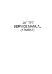
Figure 4.3: Interface of Android Appication
Figure 4.3 shows the interface of Android Application. This application can
control the mobile robot through Bluetooth wireless whether by using keypad or
accelerometer sensors inside of smartphone. The top of the screen shows connect and
disconnect button. This button is used to create the Bluetooth connection with the
paired device. For this project, BlueBee module is used and clicks the BlueBee to
36
connect it as shows at figure. The screen has joystick control part to control the
mobile robot by touch the keypad. It is also show the accelerator axes for the motion
accelerometer sensors. At the bottom position of screen has an option to choose use
accelerometer sensors to control the mobile robot.
4.4
The movement response of mobile robot
The keypad button or joystick control consist of five instructions to the
mobile robot where is the movement of the mobile robot which are forward,
backward, right, left and stop as shown at figure above. When the forward button is
touched, the application will send ‘forward’ instruction to the mobile robot through
Bluetooth wireless and the mobile robot will receive the instruction and do the task
given. It also same when other button is touched, the application will do send the
data as stated in button layer.
Action
Robot Response
Touch the forward keypad
The robot is move forward
Touch the backward keypad
The robot is move forward
Touch the right keypad
The robot is turn right
Touch the left keypad
The robot is turn left
Touch the stop keypad
The robot is stop from doing any
activities
Table 4.1: The result of using keypad
When the accelerometer sensors are activated by click at accelerometer
sensors button, the keypad cannot be used and the motion of accelerometer sensors
will be used to control the mobile robot. The motion of accelerometer sensors
consist of x, y and z accelerate axis and the value will be responding when the
smartphone move. When the accelerator axis reaches a certain value with a specific
37
condition, the application will send the data through Bluetooth to the mobile robot.
The data send is same with the keypad before which are forward, backward, right,
left and stop.
Action
When the smartphone move downward
Robot Response
The robot is move forward
position
When the smartphone move upward
The robot is move backward
position
When the smartphone move right
The robot is turn right
position
When the smartphone move left position
The robot is turn left
When the smartphone at flat position
The robot is stop from doing any
activities
Table 4.2: The result of using accelerometer sensors
Figure 4.4: The mobile robot controlled by smartphone
38
4.4
Discussions
After testing have been made rigorously, it is clear that the project achieve
the objective of this project to develop a wireless switch, however a few challenges
have been countered while developing this project.
The first challenge is the developing the communication wireless between the
mobile robot and Android smartphones. Most of the wireless application based on
previous project are using XBEE wireless for create a connection between two
devices such as the robot and computer. However for the smartphone, it has a
different wireless type with XBEE wireless which both cannot be connected directly.
Furthermore, XBEE module is only can be connected with other XBEE module
which is the smartphone needed XBEE module for itself as it will reduce the
potential of smartphone since its need to move freely with the motion of the
accelerometer sensors. This problem is solved by using the Bluetooth module as
Bluetooth module and smartphone has the same type of Bluetooth wireless
connection.
Second challenge is to develop an Android application for smartphones. At
early stage, the application is developed by using Software Development Kit which
will use java language to programming the application. However, the java coding is
quite hard to understand and it takes more than expected time required. As the
schedule goes on, the time is become limited for complete this project. After
successful developed the application, the screen is not very clearly to see that might
be because some of bad and wrong coding of programming. The application also
could not connect with Bluetooth wireless due to missing statement requirement to
establish the Bluetooth for smartphone. With using Application Inventor for
Android, this problem does not occur and the application can be used as required for
this project.
39
4.5
Summary of Chapter
The mobile robot is modified to able control it with Android Application that
has been successfully developed. The instruction given can be understand by the
mobile robot and process the data to do the task that were program in PIC
microcontroller. Besides, the problems occur during this project is bring to minimum
which not affected the output of the project.
40
CHAPTER 5
CONCLUSION AND RECOMMENDATIONS
5.1
Introduction
This chapter will explain about the conclusions of the project and
recommendation that can make for future improvements and innovations.
5.2
Conclusions
`
The first chapter stated that two objective need to be completed in order for
this project to be success. First objective is to design a mobile robot with a
communication wireless between the mobile robot and Android smartphone and
second objective is to Developing an Android application which able to use
accelerometer sensors inside smartphone to control movement of mobile robot via
wireless
The mobile robot is completed built with PIC microcontrollers and Bluetooth
Module, which the mobile robot can build the wireless connection with Android
41
smartphone. The Android application that be able to control the mobile robot also
has been successfully developed with addition can used an accelerometer sensors as
a controller. As a conclusion, this project is success as both objectives is managed to
be completed at the end of the research and wireless controller has successfully been
developed. Furthermore, the wireless controller by using Android application is
freeware and can be used by other people without need to paying the application.
5.3
Recommendations
This project can be upgraded with several improvement and innovation to
improve its functionality and more attractive .Thus, for future advancement and
research improvement in this project, following recommendations can be made:
1. Increase the type of movement of the mobile robot that can be controlled to
make its more functionality and attractive. This project has a potential as an
attractive tools to kid and teenager which can be used as a games and toys for
market business.
2. The application can be develop for other mobile operating system rather than
Android such as iOS, Windows Phone and Blackberry. The other different
type user of smartphone able to enjoy the application without needed to buy
Android smartphones.
3. The application can be developed to control other wireless devices which not
only robot, but electrical devices as well such as switch, computer and
electrical doors. In future, the smartphone will be an important devices that
must be own for everyone as it can control many other devices as the new
technology is focus to using less wire and more wireless devices because it is
more cheaper, easy to use and can save more space.
42
REFERENCES
1. G.Dudek, M.Jenkin. Computational Principles of Mobile Robotics (Cambridge –
United Kingdom – 2000).
2. Furat Barlas. Design of a Mars Rover Suspension Mechanism. Izmir Institute of
Technology, Izmir, Turkey; 2004.
3. Jussi Roivainene, et al. Smart Phone Technology Roadmap. Kaitoväylä, Oulu,
Finland; 2006.
4. Hashimi, S.Y., S. Komatineni, and D. MacLean. Introducing the Android
Computing Platform Pro Android 2. 2010, Apress. p. 1-24.
5. Mohd Bazli Mohd Mokhar. Computer Controlled mobile robot. Bachelor of
Electrical Engineering (Mechatronics), Universiti Teknologi Malaysia, Skudai; 2011.
6. Ahmad Safwan Ahmad Kamil. Android E-NOSE. Bachelor of Electrical
Engineering (Medical-Electronics), Universiti Teknologi Malaysia, Skudai; 2012.
7. Muhammad Affandy Azman. Remote Home Surveillance Using Android –
Platform Phone Through TCP/I, Bachelor in Engineering (Computer), Universiti
Teknologi Malaysia, Skudai; 2011.
8. Cytron Technologies Sdn. Bhd. Multifunction Mobile Robot Details Description.
Retrieved on 22th December 2012 from http://www.cytron.com.my/
43
9. Cytron Technologies Sdn. Bhd. BlueBee Starter Kit User Manual. Retrieved on
22th December 2012 from http://www.cytron.com.my/
10. Cytron Technologies Sdn. Bhd. LiPo Rechargeable Battery 11.1V 2200mAH
Description. Retrieved on 22th December 2012 from http://www.cytron.com.my/
11.Cytron Technologies Sdn. Bhd. RC Servo Motor C36R Introduction to RC Servo
and User’s Manual. Retrieved on
44
APPENDIX A
GANT CHART
45
FYP 1
FYP 2
46
APPENDIX B
SOURCE CODE OF PIC MICROCONTROLLER
47
//============================================================================
//
Author
:Harun Aminurasyid Bin Abu Bakar
//
Project
:Mobile Robot Controlled Android Smartphone
//
Version
:v1.00
//
Date
:May 2013
//============================================================================
//
include
//============================================================================
#include <pic.h>
//
configuration
//============================================================================
__CONFIG ( 0x3F32 );
//
define
//============================================================================
#define sw1
RE0
#define sw2
RE1
#define motor_ra
RC0
#define motor_rb
RC3
#define motor_la
RC4
#define motor_lb
RC5
#define
#define
#define
#define
s_left
s_mleft
s_mright
s_right
RB0
RB1
RB2
RB3
#define buzzer
RE2
#define
#define
#define
#define
#define
#define
RB7
RB6
PORTD
RB5
CCPR1L
CCPR2L
rs
e
lcd_data
b_light
SPEEDL
SPEEDR
#define RX_PIN
#define TX_PIN
#define BOT_ADD
RC7
RA2
100
//
global variable
//============================================================================
==================
unsigned int result;
unsigned int To=0,T=0,TH=0;
unsigned char REC;
unsigned char i=0,raw;
unsigned int us_value (unsigned char mode);
//
function prototype
//============================================================================
==================
void init(void);
void delay(unsigned long data);
void send_config(unsigned char data);
void send_char(unsigned char data);
void e_pulse(void);
48
void
void
void
void
lcd_goto(unsigned char data);
lcd_clr(void);
send_string(const char *s);
dis_num(unsigned long data);
void wireless_bluebee(void);
void
void
void
void
void
void
forward(void);
stop (void);
backward (void);
reverse (void);
left(void);
right(void);
void uart_send(unsigned char data);
unsigned char uart_rec(void);
void read_adc(char config);
//
interrupt prototype
//============================================================================
=================
static void interrupt isr(void)
{
if (TMR0IF)
// TMR0 is overflow
{
TMR0IF = 0;
// clear flag bit
To +=0x100;
// count number of TMR0 overflow
if(RBIF)
{
RBIF = 0;
if (RB4)
{
TMR0 = 0;
new count for period of RB4 high
To = 0;
}
else TH = TMR0 + To;
// save TH, RB4 high period
// there is change bit on RB4-RB7
// Rb4 is 1 mean is rising form 0
// clear all counter involved, start
// RB4 is 0 mean is falling form 1
}
if(RCIF)
{
RCIF = 0;
if (RCREG == 'R') data[i=0]= RCREG;
// clear flag bit
// check if start byte
'R' is met
else if (RCREG == 100) data[i=0]= RCREG;
// check if
start byte 'd'(decimal 100) is met
if ((data[0] == 'R'))data [i++] = RCREG;
// save the data
in data array
if (i>4) i = 4;
// if the data array reached max, set the index to 4
}
}
//
main function
//============================================================================
49
void main(void)
{
unsigned char m=0,i =0;
delay(20000);
init();
// initiate cnfiguration and initial condition
buzzer = 1;
// inditcate the circuit is on with beep
lcd_clr();
// clear the LCD screen
send_string("Press switch 1 ");
// display "select mode"
lcd_goto(20);
// move to 2nd line
send_string("to start");
// display string according to the mode
buzzer = 0;
// stop beep
while(1)
{
// loop
if (!sw1)
// if button SW2is pressed
{
while(!sw1);
// wait until button is released
switch(m)
{
case 0 :wireless_bluebee(); // bluetooth wireless
bluebee mode
break;
default :
;
}
}
}
}
//============================================================================
// Initailization
// Description : Initialize the microcontroller
//============================================================================
void init()
{
// ADC configuration
ADCON1 = 0b10000100; //set RA0 and RA1 as Analog Input, left justified
// setup for capture pwm
RBIE = 1;
PR2 = 255;
T2CON =
CCP1CON =
CCP2CON =
// Tris
TRISA =
TRISB =
TRISC =
TRISD =
TRISE =
0b00000100;
0b00001100;
0b00001100;
// enable interrupt on change of port B
// motor PWM configuration
// set period register
//
// config for RC1 to generate PWM
// config for RC2 to generate PWM
configuration (input or output)
0b00000011; //set RA0 and RA2 pin as input,other as output
0b00011111; //set RB0-RB4 pin as input, other as output
0b10000000; //set PORTC pin as output
0b00000000; //set all PORTD pin as output
0b00000011;
// TMR 0 configuation
T0CS = 0;
PSA = 0;
PS2 = 1;
PS1 = 1;
PS0 = 1;
// prescale 1:32
//
//
50
TMR0IE = 1;
TMR0 = 0;
//setup UART
SPBRG = 0x81;
BRGH = 1;
TXEN = 1;
TX9 = 0;
CREN = 1;
SPEN = 1;
RX9 = 0;
RCIE = 1;
// TMR0 Interrupt
//set baud rate to 9600 for 20Mhz
//baud rate high speed option
//enable transmission
//enable reception
//enable serial port
//enable interrupt on eachdata received
// enable all unmasked interrupt
GIE = 1;
PEIE = 1;
// LCD configuration
send_config(0b00000001);
send_config(0b00000010);
send_config(0b00000110);
send_config(0b00001100);
send_config(0b00111000);
//clear display at lcd
//Lcd Return to home
//entry mode-cursor increase 1
//diplay on, cursor off and cursor blink off
//function
TX_PIN = 1;
b_light = 0;
buzzer = 0;
stop();
}
//============================================================================
// Bluetooth wireless
// Description : Control the robot using UART (BlueBee Bluetooth Module)
//============================================================================
void wireless_bluebee (void)
{
lcd_clr();
lcd_goto (0);
// clear the lcd
RCIF = 0;
SPEEDL = 255;
// set the motor speed
SPEEDR = 255;
while(1)
{
lcd_goto(20);
if (RCREG == 'W')
// if character 'W' is detected, the robot move forward
{
forward();
send_string("FORWARD
");
}
else if (RCREG == 'S')
// if character 'S' is detected, the robot move backward
{
backward();
send_string("BACKWARD
");
}
else if (RCREG == 'D' )
// if character 'D' is detected, the robot turn right
51
{
right();
send_string("TURN RIGHT
");
}
else if (RCREG == 'A')
// if character 'A' is detected, the robot turn left
{
left();
send_string("TURN LEFT
");
}
else if (RCREG == 'X')
// if character 'X' is detected, then stop the robot
{
stop();
send_string("STOP ");
}
else
// else then stop the robot
{
stop();
send_string("INSERT COMMAND ");
}
}
}
//============================================================================
// Motor control function
// Description : subroutine to set the robot moving direction
//============================================================================
void forward ()
{
motor_ra = 0;
motor_rb = 1;
motor_la = 0;
motor_lb = 1;
}
void backward ()
{
motor_ra =
motor_rb =
motor_la =
motor_lb =
}
void left()
{
motor_la
motor_lb
motor_ra
motor_rb
}
void right()
{
motor_la
motor_lb
=
=
=
=
1;
0;
1;
0;
1;
0;
0;
1;
= 0;
= 1;
52
motor_ra = 1;
motor_rb = 0;
}
void stop()
{
motor_la
motor_lb
motor_ra
motor_rb
}
=
=
=
=
1;
1;
1;
1;
//============================================================================
//
LCD
functions
//============================================================================
void delay(unsigned long data)
//delay function, the delay time
{
for( ;data>0;data-=1);
//depend on the given value
}
void send_config(unsigned char data)
{
rs=0;
lcd_data=data;
delay(400);
e_pulse();
}
void send_char(unsigned char data)
{
rs=1;
lcd_data=data;
delay(400);
e_pulse();
}
void e_pulse(void)
{
e=1;
delay(300);
e=0;
delay(300);
}
//send lcd configuration
//set lcd to config mode
//lcd data port = data
//pulse e to confirm the data
//send lcd character
//set lcd to display mode
//lcd data port = data
//pulse e to confirm the data
//pulse e to confirm the data
void lcd_goto(unsigned char data)
//set the location of the lcd cursor
{
if(data<16)
//if the given value is (0-15) the
{
//cursor will be at the upper line
send_config(0x80+data);
}
else
//if the given value is (20-35) the
{
//cursor will be at the lower line
data=data-20;
//location of the lcd cursor(2X16):
send_config(0xc0+data);
// ---------------------------------------------------}
// | |00|01|02|03|04|05|06|07|08|09|10|11|12|13|14|15| |
}
// | |20|21|22|23|24|25|26|27|28|29|30|31|32|33|34|35| |
// -----------------------------------------------------
53
void lcd_clr(void)
{
send_config(0x01);
delay(350);
}
void send_string(const char *s)
{
while (s && *s)send_char (*s++);
}
//clear the lcd
//send a string to display in the lcd
void dis_num(unsigned long data)
{
unsigned char hundred_thousand;
unsigned char ten_thousand;
unsigned char thousand;
unsigned char hundred;
unsigned char tenth;
hundred_thousand = data/100000;
// devide to get the numerator
eg: 5234/1000 = 5
data = data % 100000;
// modulas to get the remainder
eg: 5234%1000 = 234
ten_thousand = data/10000;
data = data % 10000;
thousand = data / 1000;
data = data % 1000;
hundred = data / 100;
data = data % 100;
tenth = data / 10;
data = data % 10;
send_char(hundred_thousand + 0x30);
ASCII code char '0' to '9'
send_char(ten_thousand + 0x30);
send_char(thousand + 0x30);
send_char(hundred + 0x30);
send_char(tenth + 0x30);
send_char(data + 0x30);
}
//0x30 added to become
//============================================================================
// uart function
//============================================================================
void uart_send(unsigned char data) //function to send out a byte via uart
{
while(TXIF==0);
//wait for previous data to finish send out
TXREG=data;
//send new data
}
unsigned char uart_rec(void)//function to wait for a byte receive from uart
{
unsigned char temp;
while(RCIF==0);
//wait for data to received
temp=RCREG;
return temp;
//return the received data
}