1
MT5634HD8/16 User Guide
MT5634HD8/16 User Guide
P/N 82074700, Revision A
Copyright © 1997 by Multi-Tech Systems, Inc.
All rights reserved. This publication may not be reproduced, in whole or in part, without prior expressed
written permission from Multi-Tech Systems, Inc.
Multi-Tech Systems, Inc. makes no representation or warranties with respect to the contents hereof and
specifically disclaims any implied warranties of merchantability or fitness for any particular purpose.
Furthermore, Multi-Tech Systems, Inc. reserves the right to revise this publication and to make changes
from time to time in the content hereof without obligation of Multi-Tech Systems, Inc., to notify any
person or organization of such revisions or changes.
Revision
Date
A
11/15/97
Description
Manual released.
Multi-Tech, CommPlete, RASExpress, MultiExpress, MultiExpress Fax MultiModem, MultiModemZDX,
MultiCommManager, and the Multi-Tech logo are trademarks of Multi-Tech Systems, Inc. Other
trademarks and trade names mentioned in this publication belong to their respective owners.
Multi-Tech Systems, Inc.
2205 Woodale Drive
Mounds View, Minnesota 55112
(612) 785-3500 or (800) 328-9717
U.S. Fax (612) 785-9874
Technical Support (800) 972-2439
BBS (612) 785-3702 or (800) 392-2432
Fax Back (612) 717-5888
Internet Address: http://www.multitech.com
Federal Communications Commission Statement
This equipment has been tested and found to comply with the limits for a Class A digital device, pursuant
to Part 15 of the FCC Rules. These limits are designed to provide reasonable protection against harmful
interference when the equipment is operated in a commercial environment. This equipment generates,
uses, and can radiate radio frequency energy, and if not installed and used in accordance with the
instruction manual, may cause harmful interference to radio communications. Operation of this
equipment in a residential area is likely to cause harmful interference, in which case the user will be
required to correct the interference at his own expense.
Warning: Changes or modifications to this unit not expressly approved by the party responsible for
compliance could void the user’s authority to operate the equipment.
FCC Regulations for Telephone Line Interconnection
1.
No repairs are to be made by you. Repairs are to be made only by Multi-Tech Systems or its
licensees. Unauthorized repairs void registration and warranty. Contact Multi-Tech Systems, Inc. for
details of how to have repairs made.
2.
When trouble is experienced, you must disconnect your modem from the telephone company’s jack
to determine the cause of the trouble, and reconnect your modem only when the trouble is
corrected.
3.
The modem cannot be connected to pay telephones or party lines.
4.
If requested by the telephone company, you must notify them of the following before the
MT5634HD8/16 is installed:
a.
The particular phone line (phone number) to which the connection is to be made.
b.
The FCC Registration Number. (See your CC9600 Chassis User Guide for specifics.)
c.
The manufacturer’s name and model number:
Multi-Tech Systems - Model MT5634HD8 or MT5634HD16
5.
If the telephone company notifies you that your device is causing harm, unplug it. The telephone
company may disconnect your service if necessary and also may change its facilities, equipment,
operations or procedures which may affect operation of your equipment. Where practical, the
telephone company must promptly inform you in writing of the temporary disconnect or change in
service, give you the opportunity to make changes allowing uninterrupted service, and inform you of
your rights to bring a complaint to the FCC.
CommPlete Communications Server
iii
FCC Fax Warning
The Telephone Consumer Protection Act of 1991 makes it unlawful for any person to use a computer or
other electronic device to send any message via a telephone fax machine unless such message clearly
contains in a margin at the top or bottom of each page or the first page of the transmission, the date and
time it is sent and an identification of the business or other entity, or other individual sending the message
and the telephone number of the sending machine or such business, other entity, or individual.
See your fax software manual for setup details.
Canadian Limitations Notice
Notice: The ringer equivalence number (REN) assigned to each terminal device provides an indication of
the maximum number of terminals allowed to be connected to a telephone interface. The termination of a
interface may consist of any combination of devices subject only to the requirement that the sum of the
ringer equivalence numbers of all the devices does not exceed 5.
Notice: The Industry Canada label identifies certificated equipment. This certification means that the
equipment meets certain telecommunications network protective, operational and safety requirements.
Industry Canada does not guarantee the equipment will operate to the user’s satisfaction.
Before installing this equipment, users should ensure that it is permissible to be connected to the facilities
of the local telecommunications company. The equipment must also be installed using an acceptable
method of connection. The customer should be aware that compliance with the above conditions may not
prevent degradation of service in some situations.
Repairs to certified equipment should be made by an authorized Canadian maintenance facility designated
by the supplier. Any repairs or alterations made by the user to this equipment, or equipment
malfunctions, may give the telecommunications company cause to request the user to disconnect the
equipment.
Users should ensure for their own protection that the electrical ground connections of the power utility,
telephone lines and internal metallic water pipe system, if present, are connected together. This precaution
may be particularly important in rural areas.
Caution: Users should not attempt to make such connections themselves, but should contact the
appropriate electric inspection authority, or electrician, as appropriate.
See your CC9600 User Guide for complete Canadian Limitations information.
iv
CommPlete Communications Server
Table of Contents
1 Introduction
Introduction ...................................................................................................................................................... 2
Manual Organization......................................................................................................................................... 2
LED Indicators................................................................................................................................................... 3
Power Supplies .................................................................................................................................................. 3
Technical Specifications.................................................................................................................................... 4
2 Installation
Introduction ...................................................................................................................................................... 8
Safety Warnings................................................................................................................................................. 8
Pre-Installation Notes ....................................................................................................................................... 9
Installation Procedure....................................................................................................................................... 9
3 AT Commands
Working with AT Commands ..........................................................................................................................12
Modes of Operation .....................................................................................................................................12
Command Structure ....................................................................................................................................12
Command Editing........................................................................................................................................13
Dialing Commands...........................................................................................................................................15
Dial Modifier Commands.................................................................................................................................16
Phone Number Memory Commands...............................................................................................................18
Configuration Storage and Recall Commands.................................................................................................19
Modem Response (Result Code) Commands..................................................................................................19
Online Connection Commands........................................................................................................................22
RS-232 Interface Commands ...........................................................................................................................24
Error Correction and Data Compression Commands .....................................................................................26
Immediate Action Commands.........................................................................................................................27
Flow Control Commands .................................................................................................................................27
Escape Sequences .............................................................................................................................................29
Diagnostic Commands .....................................................................................................................................31
Speaker Settings................................................................................................................................................31
4 S-Registers
Introduction .....................................................................................................................................................34
S-Registers ........................................................................................................................................................34
Reading and Assigning S-Register Values .......................................................................................................38
Examples of Assigning Values.....................................................................................................................38
Examples of Reading Values .......................................................................................................................39
AT Commands that Affect S-Registers ............................................................................................................39
CommPlete Communications Server
v
Appendix A ASCII Conversion Chart ........................................... 42
Appendix B Dial Pulses and Tones............................................... 43
Appendix C Result Code Summary .............................................. 45
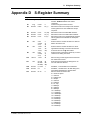
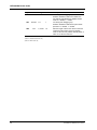
Appendix D S-Register Summary................................................... 47
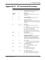
Appendix E AT Command Summary ........................................... 49
Glossary .............................................................................................................. 57
Index....................................................................................................................... 71
vi
CommPlete Communications Server
1
CommPlete Communications Server
Introduction
1
MT5634HD8/16 User Guide
Introduction
The Multi-Tech MT5634HD8 and MT5634HD16 are high speed, high density modem cards for the
CommPlete Communications Server. Each MT5634HD8 contains eight integrated 56Kflex modems, and
each MT5634HD16 card contains sixteen integrated 56Kflex modems. Each modem on the card can be
configured independently of the others via RASexpress Software or the CommPlete Communications
Server’s MR9600 controller. The MT5634HD8/16 cards can be used in various combinations according to
the desired segment type; T1, PRI or Dual T1. There are no external connectors.
Three MT5634HD8 card must be installed per T1 segment. With eight modems per card, the CommPlete
Communications Server can support up to 24 simultaneous data line per segment.
One MT5634HD16 card and one MT5634HD8 card must be installed per PRI segment. With sixteen
modems per MT5634HD16 card and eight modems per MT5634HD8 card, the CommPlete
Communications Server can support up to 24 simultaneous data lines per segment. Analog calls are routed
to the MT5634HD16’s modems through a Primary Rate Interface (PRI) card which plugs into the slot next
to the RASCard that controls the segment. ISDN calls are routed to the PRI where its “B” channel(s)
process the call.
Three MT5634HD16 cards must be installed per Dual T1 segment. With sixteen modems per
MT5634HD16 card the CommPlete Communications Server can support up to 48 simultaneous data lines
per segment.
The MT5634HD8/16 operates as an enhanced ITU-T V.34 dial-up modem with a maximum K56flex
speeds, and is a fully digital K56flex server. As such, it includes the advanced features of other popular
Multi-Tech standalone modems.
The MT5634HD8/16 is registered by the FCC for direct connection to the public telephone networks. No
Data Access Arrangements (DAAs) are required.
The MT5634HD8/16 is fully compatible with the standard AT command set, and is therefore compatible
with all popular communications software packages.
This user guide will help you to install, configure, test, and use the MT5634HD8/16.
Manual Organization
Chapter 1
Introduction
This chapter describes the MT5634HD8/16 and its LED indicators, gives its technical specifications, and
provides a guide to the organization of the manual.
Chapter 2
Installation
This chapter describes how to install the MT5634HD8/16 into the CC9600 chassis.
Chapter 3
Command Mode Operation
This chapter provides an introduction to MT5634HD8/16 command mode fundamentals, followed by a
detailed explanation of each AT command, providing examples where applicable.
Chapter 4
S-Registers
This chapter describes the MT5634HD8/16’s S-registers, which are used to store various modem options.
2
CommPlete Communications Server
1 Introduction
Appendix A ASCII Conversion Chart
Appendix B Dial Pulses and Tones
Appendix C Result Code Summary
Appendix D S-Register Summary
Appendix E AT Command Summary
Appendix F Remote Configuration
Glossary
Index
LED Indicators
The MT5634HD8 has 16 LED indicators (the MT5634HD16 has 32 LEDs) on the front panel, two for each
modem:
CD Carrier Detect. The CD LED lights when the modem detects a valid carrier signal.
OH Off Hook/Out of Service. The OH LED lights when the modem is off hook, which occurs when the
modem is dialing, online, or answering a call. The LED flashes when the modem is in the busy-out
or out-of-service state.
Power Supplies
DC voltages are supplied to all modems in the CC9600 rack through two PS9600 universal input switching
power supplies designed for conventional 115 or 230 VAC input. The power supplies are designed for
redundant, fail-safe operation. If one should fail, the other can supply the power requirements of the entire
CommPlete Communications Server. Each PS9600 power supply has one LED indicator that indicates the
presence of all supply voltages.
CommPlete Communications Server
3
MT5634HD8/16 User Guide
Technical Specifications
Model Numbers
MT5634HD8 and MT5634HD16
Data Rates (Modem) Eight or sixteen independent modems (Modem A, B, C, D, E, F, G, H), each
operating as follows:
Downloads at speeds to 56K bps when calling a fully digital K56flex server
(actual connect speed depends on line conditions).
Uploads and other connections at 33,600, 31,200, 28,800, 26,400, 24,000,
21,600, 19,200, 16,800, 14,400, 12,000, 9600, 4800, 2400, 1200, or 0-300 bps
Data Rates (Fax)
14,400, 9600, 4800, and 2400 bps
Data Format
(Modem)
Serial, binary, asynchronous at all data rates
Configuration
Each of the card’s modems is independently configurable
Compatibility (Modem) ITU-T V.42bis, V.42, V.34, ITU-T V.32bis, V.32, V.25bis, V.21, V.22bis, V.22,
V.23, V.17, Bell 212A* and 103/113*, K56flex
Compatibility (Fax)
ITU-T Group 3, T.4, T.30, V.21, V.27ter, V.29, V.17, and EIA TR29.2
Error Correction
ITU-T V.42 (MNP® Classes 3 and 4, and LAP-M)
Data Compression
ITU-T V.42bis (4:1 throughput) or MNP 5 (2:1 throughput)
Speed Conversion
Serial port data rates adjustable to 300, 1200, 2400, 4800,9600, 19,200, 38,400,
57,600, and 115,200 bps
Flow Control
XON/XOFF, CTS/RTS
Mode of Operation
Half or full duplex over dial-up lines; automatic or manual dialing, automatic
or manual answer
Intelligent Features
Fully AT command compatible; auto dial; redial; repeat dial*; pulse or tone
dial; dial pauses; call status display; auto-parity and data rate selection;
keyboard-controlled modem options; nonvolatile memory; on-screen
displays of modem parameters, stored telephone numbers, and help menus.
AT Commands
100% compatible with standard AT command set
Command Buffer
40 characters
Automatic Dialing
Standard AT command asynchronous dialing
Modem Modulations FSK at 300 bps, PSK at 1200 bps, QAM at 2400, 4800, and 9600 bps (nontrellis), QAM with trellis-coded modulation (TCM) at 9600, 12,000, 14,400,
16,800, 19,200, 21,600, 24,000, 26,400, 28,800, 31,200, 33,600, plus K56flex
speeds
Fax Modulations
V.21 CH2 FSK at 300 bps
V.27ter DPSK at 4800 and 2400 bps
V.29 QAM at 9600 and 7200 bps
V.17TCM at 14400, 12000, 9600, and 7200 bps
Carrier Frequencies 1600, 1646, 1680, 1800, 1829, 1867, 1920, 1959, 2000 Hz
ITU-T V.34
Carrier Frequencies: 1800 Hz
AT&T V.32terbo/
4
CommPlete Communications Server
1 Introduction
ITU-T V.32bis/V.32
Carrier Frequencies:
V.22bis/V.22 or
Bell 212A Standard
(2400 & 1200 bps)
Transmit originate:
Transmit answer:
Receive originate:
Receive answer:
Carrier Frequencies: Transmit originate:
Bell 103/113
Receive originate:
(300 bps)
Transmit answer:
Receive answer:
Carrier Frequencies: Transmit originate:
V.21
Receive originate:
Transmit answer:
Receive answer:
Carrier Frequencies: Transmit originate:
V.23
Receive originate:
Transmit answer:
Receive answer:
1200 Hz
2400 Hz
2400 Hz
1200 Hz
1270 Hz mark
1070 Hz space
2225 Hz mark
2025 Hz space
2225 Hz mark
2025 Hz space
1270 Hz mark
1070 Hz space
980 Hz mark
1180 Hz space
1650 Hz mark
1850 Hz space
1650 Hz mark
1850 Hz space
980 Hz mark
1180 Hz space
390 Hz mark
450 Hz space
1300 Hz mark
2100 Hz space
1300 Hz mark
2100 Hz space
390 Hz mark
450 Hz space
Fax Modulations
V.21Ch2 FSK at 300 bps
V.27ter DPSK at 4800 and 2400 bps
V.29 QAM at 9600 and 7200 bps
V.17 TCM at 14400, 12000, 9600, and 7200 bps
Fax Carrier
Frequencies
V.21 CH2 (half duplex)
1650 Hz mark, 1850 Hz space for transmit originate
1650 Hz mark, 1850 Hz space for transmit answer
V.27ter: 1800 Hz Originate/Answer
V.29 QAM: 1700 Hz Originate/Answer
V.17 TCM: 1800 Hz Originate/Answer
Transmit Level
-13 dBm
Frequency Stability
+0.01%
Receiver Sensitivity -43 dBm under worst case conditions
AGC Dynamic Range 43 dB
Interface
TIA / EIA RS-232/ITU-T V.24/V.28
Diagnostics
Power-on self-test, local analog loop, local digital loop, remote digital loop.
CommPlete Communications Server
5
MT5634HD8/16 User Guide
Firmware Upgrades
Flash memory; available on Multi-Tech’s BBS and website
Indicators
LEDs for Carrier Detect and Off Hook/Out-Of-Service
Environmental
Temperature range: 0°–50° C (32°–120° F)
Humidity range: 20–90% (noncondensing)
Power
Requirements:
MT5634HD8
5 VDC at 1.5 A (MT5634HD8)
MT5634HD16
5 VDC at 3.0 A (MT5634HD16)
Dimensions
23.3 × 2.3 × 29.2 cm (9.2 × 0.9 × 11.5 in.) H × W × D
Weight:
MT5634HD8
14 oz.
MT5634HD16
1 lb.
Limited Warranty
6
Two years
CommPlete Communications Server
2
CommPlete Communications Server
Installation
7
MT5634HD8/16 User Guide
Introduction
This chapter describes how to install the MT5634HD8/16 modem card into a CommPlete Communication
Server CC9600 chassis. This equipment should be installed only by a qualified service person.
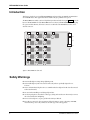
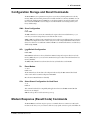
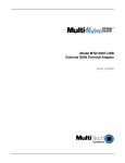
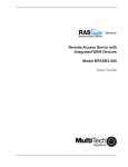
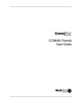
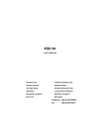
The MT5634HD8/16 assembly consists of a high-density modem card and a front panel. Figure 1 shows the
layout of the MT5634HD16 card (the MT5634HD8 card is not shown). The MT5634HD8/16 assembly plugs
into power and data, Ethernet, and T1 bus connectors on the inside of the CC9600 chassis. There are no
external connectors.
48 pin
96 pin
24 pin
LEDs
Figure 1. MT5634HD16 modem card.
Safety Warnings
✔ Never install telephone wiring during a lightning storm.
✔ Never install telephone jacks in wet locations unless the jacks are specifically designed for wet
locations.
✔ Never touch uninsulated telephone wires or terminals unless the telephone line has been disconnected
at the network interface.
✔ Use caution when installing or modifying telephone lines.
✔ Avoid using a telephone (other than a cordless type) during an electrical storm. There may be a remote
risk of electrical shock from lightning.
✔ Do not use the telephone to report a gas leak in the vicinity of that leak.
✔ Ports that are connected to other apparatus are defined as SELV. To ensure conformity to EN 41003,
ensure that these ports are only connected to the same type on the other apparatus.
8
CommPlete Communications Server
2 Installation
Pre-Installation Notes
Warning: Direct interconnection (or connection by way of other apparatus) of ports marked “SAFETY
WARNING see instructions for use” with any other ports (whether or not similarly marked) may
produce hazardous conditions on the network.
MultiTech strongly urges you to consult a qualified engineer before attempting to make this type of
connection.
• All installation must be done by a qualified service person.
• To reduce emissions, be sure to use blanking plates to cover empty slots in the CC9600 chassis.
• Cable, wiring, and any other apparatus connected between the MT5634HD8/16K modem and the point
of connection to any speech band circuit shall comply with the following:
1.
The overall characteristics of the apparatus shall be such as to introduce no material effect upon
the electrical conditions presented to one another by the modem and the speech band circuit.
2.
The apparatus shall comprise only
a.
apparatus approved for the purpose of connection between the modem and a speech band
circuit; and
b.
cable and wiring complying with a code of practice for the installation of equipment
covered by this part of BS 6328 or such other requirements as may be applicable.
Note: Such apparatus may have been approved subject to limitations in its use.
Installation Procedure
1.
Unpack the MT5634HD8/16 assembly from its factory packaging. (You may wish to save the
packaging for possible future use.)
2.
Perform a visual inspection of the MT5634HD8/16. If you are concerned about its condition, call
Technical Support for instructions.
3.
The MT5634HD8/16 must be installed in a segment in which a RASCard is installed. Turn off the
RAS segment where the MT5634HD8/16 will be installed. (Turn off power to this segment.)
4.
Remove a blank device front panel or previous MT5634HD8/16 card from the RAS segment used in
step 3. Do not remove the back panel.
5.
Support the MT5634HD8/16 by the front panel and the bottom edge of the card, and carefully place
it into the CC9600’s open device slot. Make sure the edges of the MT5634HD8/16 card mate properly
with the guides of the device slot.
6.
Slide the MT5634HD8/16 into the CC9600 chassis until you feel the MT5634HD16’s connectors mate
with the CC9600’s bus connectors.
CommPlete Communications Server
9
MT5634HD8/16 User Guide
7.
Tighten the MT5634HD8/16’s retaining screws.
8.
Repeat steps 1 through 7 for each of the MT5634HD8/16’s you are installing. Three MT5634HD8’s
must be installed for each T1 segment, three MT5634HD16’s must be installed for each Dual T1
segment, and one MT5634HD16 and one MT5634HD8 must be installed for each PRI segment.
9.
Turn on power to the RASCard segment.
10.
Check the LED indicators on the RASCard and the controllers. If the LEDs on the controller do not
light, turn off the RASCard segment. Reseat the cards by repeating steps 5 through 9. If you continue
to experience problems, consult your CommPlete Owner’s Manual for troubleshooting tips.
Note: A self-test runs each time the CommPlete Communications Server is turned on. Refer to your
system Owner’s Manual for more details on the power-on self-test.
10
CommPlete Communications Server
3
CommPlete Communications Server
AT Commands
11
MT5634HD8/16 User Guide
Working with AT Commands
The MT5634HD8/16’s modems are controlled by instructions called AT commands, so called because the
attention characters AT precede each command or sequence of commands (known as a command string).
You can send commands to the modem from your keyboard while in terminal mode, or you can use
communications software to issue these commands automatically.
The modem is in command mode when it is not dialing or online. When it is in command mode, you have
access to a complete communications system that allows you to use several features, including the basic
AT command set described in this chapter. Using the basic AT command set, you can enter phone
numbers for automatic dialing, configure modem options, and monitor telephone activity. In addition,
you can command your modem to perform advanced features such as error correction, data compression,
speed conversion, and more.
This chapter describes the modem’s operational modes, and shows you how to use each of the modem’s
AT commands. These commands and responses are compatible with all systems and with all data
communications software using the AT command set.
Modes of Operation
The MT5634HD8/16 operates in two basic functional modes: command mode and online mode. (There is
also an in-between state, wait-for-carrier, in which the modem is out of command mode but not yet
online.) When you power up the modem, it is in command mode, and is ready to accept and respond to
commands from your keyboard or software.
The modem enters online mode after it dials, connects with another modem, and detects a valid carrier
signal. If it does not detect a carrier signal within the time frame controlled by register S7, the modem
abandons the call and re-enters command mode.
You can make the modem enter online mode without dialing by typing either the D command or the A
command.
The modem exits online mode if the carrier signal is lost or intentionally dropped. When this happens, the
modem hangs up and re-enters command mode.
By sending certain “escape” characters to the modem while online, you can make it enter command mode
without losing the carrier signal.
Command Structure
You can control a wide variety of modem operations and options when the modem is in command mode.
AT commands tell the modem to dial a number, to answer a call, to operate at a certain speed, to use a
certain compression technique, and many other functions. AT commands consist of one or two letters,
which may be preceded by an ampersand (&), a percent character (%), or a slash character (\). The Q
command, for example, determines whether the modem returns result codes, while the &Q command
selects the asynchronous communications mode.
12
CommPlete Communications Server
3
AT Commands
A parameter after a command (0, 1, 2, etc.) tells the modem which option to use. If you do not specify a
parameter, the modem assumes the 0 (zero) option. E, for example, is the same as E0. You can issue
several commands on a single line (a command string) as long as the line does not exceed 40 characters.
Note: Each character in a command counts towards the 40 character command line maximum. While Q1
is a single command, it counts as two characters in the command line.
Each command has a valid range of parameters; for example, &S can have only 0 or 1 as a parameter. Valid
commands always generate an OK result code, and a few generate an additional response, such as a list of
parameters. An invalid command, such as &S3, which has a parameter outside the valid range, generates
an ERROR result code. Most commands have a default parameter that is enabled when the modem is
turned on or reset with the ATZ or AT&F command. Factory defaults are stored in read-only memory
(ROM), and cannot be changed. User-defined defaults can be stored in nonvolatile random-access
memory (NVRAM), and can be changed or deleted at will.
Command Editing
Always begin a command with the letters AT. Enter the entire command string in upper or lower case, but
do not cannot mix cases within the command string. The AT command is not executed until you press the
ENTER key. Use the BACKSPACE key to erase the previous command character. It will not erase the AT
characters once they are typed. If your keyboard has no BACKSPACE key, use CTRL+H. (You can change the
character recognized by the modem as BACKSPACE to any other ASCII character by changing register S5.)
Press CTRL+X to cancel an entire command that has been typed but not yet executed. This also clears the
command buffer. The effect is the same as backspacing the command, only quicker.
The modem stores characters entered in a command in it’s command buffer until they are executed by
pressing ENTER. The command buffer’s capacity is 40 characters. The attention characters (AT) do not
count towards the 40 character command line maximum. You may use spaces for increased readability
when typing a command. Spaces are not stored in the command buffer, and they do not count towards the
40 character command line maximum. Special characters, such as hyphens and parentheses, are not
allowed.
If you exceed the 40-character limit or type invalid characters, the command buffer is automatically erased
and an ERROR message displays. You should retype the command within the 40-character limit, using
only the allowed characters.
The commands in this chapter are organized by function. A brief summary follows.
CommPlete Communications Server
13
MT5634HD8/16 User Guide
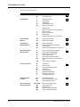
Table 1. AT Commands by Function
Topic
Dialing Action
Command
D
H
Dial Modifiers
L
P
T
V
W
Redial last number
Pulse dialing
Tone dialing
Speakerphone mode
Wait for new dial tone
,
;
!
$
@
^
Dialing pause
Return to command mode after dialing
Flash on-hook
Detect call card tone
Quiet answer
Disable data calling tone transmission
Phone Number
Memory
&Z
DS
Store a phone number
Dial a stored number
18
Configuration
Storage & Recall
&W
&F
Z
&Y
Store configuration
Load factory default configuration
Reset modem
Select stored configuration on power-up
18
Modem Responses
(Result Codes)
E
Q
V
\V
X
&Q
19
%B
Echo command mode characters
Result codes: enable/disable
Result codes: verbose/terse
Protocol result code
Result codes and call progress
Select asynchronous communications
mode
View numbers in blacklist
Online Connection
B
C
F
&G
-C
N
\T
Y
Answer tone
Carrier control
Echo online data characters
Guard tones
Data calling tone
Modulation handshake
Disable inactivity timer
Long space disconnect
22
RS-232 Interface
Controls
&C
&D
&S
Carrier Detect control
Data Terminal Ready control
Data Set Ready control
24
Non-error correction mode
Auto-reliable mode
Reliable mode
Data compression disabled
Data compression enabled
26
Error Correction &
Data Compression
14
\N0 or &Q6
\N3
\N2
%C0
%C1
Description
Dial
On-hook/off-hook
Page
15
16
CommPlete Communications Server
3
AT Commands
Topic
Immediate Action
Command
A/
I
&B
&V
Description
Repeat last command
Information request
V.32 auto retrain
View current configuration
Page
27
Flow Control
&M0
&K0 or \Q0
&K3 or \Q3
&K4 or \Q1
\X0
&J
\J
\G
\K
+ES=6
Asynchronous mode
Flow control disabled
Hardware flow control
XON/XOFF flow control
XON/XOFF no pass-through
Auxiliary relay control
Enable data buffer control
Modem port flow control
Set break control
Enable synchronous buffered mode
27
Escape
Sequences
+++AT<CR>
A
O
Default in-band escape sequence
Force answer mode
Go back online
29
Diagnostics
&T
Self-test commands
31
Speaker Settings
L
M
Monitor speaker volume
Monitor speaker mode
31
Dialing Commands
Dialing commands are used to dial and hang up.
Ds
Dial
s = phone number
Default: none
The letter D in a command causes the modem to dial the telephone number immediately following it. For
example, if you type ATD5551212<CR>, the modem dials the number 555-1212.
The MT5634HD8/16 supports several dialing methods. With the D command, you can specify either pulse
(ATDP) or tone (ATDT) dialing. You can also modify the dialing command with several other characters
that are explained in the section “Dial Modifier Commands”, later in this chapter.
The modem also lets you select either smart (wait-for-dial-tone) dialing or blind dialing. With smart
dialing, the modem waits for and detects dial tones and busy signals. With blind dialing, the modem works
with timed pauses (determined by the value of register S6), not dial tone and busy signal detection. See the
X command for more information on blind and smart dialing.
CommPlete Communications Server
15
MT5634HD8/16 User Guide
Hn
On-Hook/Off-Hook
n = 0 or 1
Default: 0
Use the H command to make the modem hang up (go on-hook) or simulate the action of picking up a
telephone handset (go off-hook).
H0 (or H) hangs up the modem
H1 brings the line off-hook, just as if you had picked up the telephone handset.
It is not necessary to use the H1 command to bring the line off-hook when using the D command. The
modem automatically goes off-hook when you press ENTER at the end of the dial command.
Dial Modifier Commands
The dial string can include the digits 0 through 9, the pound sign (#), the asterisk (*), and the letters A, B,
C, or D. The latter are used by some PBXs; the exact function will depend on the PBX manufacturer’s
feature set and implementation. There are also several command characters, called “dial modifiers,” that
can be included within a dialing command after the letter D. Their functions include pulse or tone dialing,
pauses in the dial sequence, automatic redials if a number is busy, and reverting to command mode or
switching to answer mode after dialing.
L
Redial Last Number
Default: none
You can redial the last number dialed by entering L immediately following the dial command (ATD). This
command is handy if you encounter a busy signal and want to try the call again.
P, T
Pulse or Tone Dialing
Default: T
The MT5634HD8/16’s modems can dial numbers by using pulse dialing, tone dialing, or a combination of
both methods. Pulse dialing, used by rotary-dial telephones, uses the timed opening and closing of a relay
to encode the numbers. Tone dialing, used by push-button (touch-tone) telephones, uses dual tone
multifrequency (DTMF) dialing.
P selects pulse dialing.
T selects tone dialing.
Insert P or T in the dialing command just before the digits you want to pulse- or tone-dial. If neither pulse
nor tone dialing is specified in the dial command, the modem uses whatever method was used last.
Note: When your modem is first turned on or reset, it uses the tone dialing method, (which is the default),
even if you do not include T in your dial command.
16
CommPlete Communications Server
3
AT Commands
Examples:
To pulse-dial the number 555-1212, type ATDP5551212 and press ENTER.
To tone-dial the same number, type ATDT5551212 and press ENTER.
To call out of a PBX (switchboard) system where a 9 has to be pulse-dialed, and the rest of the number has
to be tone-dialed after pausing for a second dial tone, type ATDP9,T5551212 and press ENTER. (The
comma causes a pause.)
V
Switch to Speakerphone Mode
Inserting V into the dialing command causes the modem to switch to speakerphone mode and dial the
following number. Use ATH to hang up.
W
Wait for New Dial Tone
Inserting W into the dialing command causes the modem to wait for another dial tone before it resumes
dialing. (It is not necessary to enter W at the beginning of the dialing command.)
Note: Because the modem must be able to detect the dial tone for this command to work, you also must
select wait-for-dial-tone dialing with the X2 or X4 command.
,
Dialing Pause
Enter a comma in the dialing string to make the modem pause while dialing. This pause lasts two seconds
(North American models) or four seconds (U.K. and International models) for each comma entered. You
can force longer pauses by entering multiple commas, or you can change the length of the pause caused by
a comma by setting register S8 to any value from 0 through 255 seconds (North American), 4 through 7
seconds (U.K.) or 4 through 255 seconds (International).
Note: Each comma in a dialing command counts as one of the 40 allowed characters.
;
Return to Command Mode After Dialing
Enter a semicolon (;) as the last character of a dialing command to cause the modem to return to
command mode immediately after executing the command instead of waiting for a carrier signal and
going online.
For example, type ATDT5551212; to tone-dial the number and immediately go back into command
mode. The semicolon is useful when modem data transfer is not desired, as in voice communications, or
in applications using touch tones as a data entry method, such as bank-by-phone.
!
Flash On-Hook
Some switchboard systems react to a momentary on-hook condition. Insert an exclamation mark into the
dialing command to cause the modem to “flash” on-hook for half a second, just as if you had pressed the
switch hook on a telephone set for half a second. (With U.K. models, the exclamation mark causes the
modem to flash on-hook for 90 milliseconds.)
For example, to flash on-hook to transfer to extension 5678 after dialing the number 555-1234, type
ATDT5551234,,!5678. The commas cause a 4-second pause.
CommPlete Communications Server
17
MT5634HD8/16 User Guide
$
Detect Call Card Tone
Use the $ command to dial services that require you to enter your call card number after a tone. The $
character in the dialing string causes the modem to pause and wait for an AT&T call card “bong” or a 1600
Hz tone. When the modem detects the tone, it processes the rest of the dialing string. If it does not detect
the tone within the time set in register S7, the modem stops processing the dial string with a NO
CARRIER message. Pressing any key also terminates the $ command.
@
Quiet Answer
Use the @ command to access a system that does not provide a dial tone. The @ command causes the
modem to wait before processing the next character in the dialing string. The wait is for one or more rings
back followed by five seconds of silence.
For example, ATDT5551212@6313550 causes the modem to dial the first number (555-1212), then
wait for the time specified in register S7 for at least one ringback and five seconds of silence. If the modem
detects a busy signal, it hangs up and generates a BUSY result code. If it does not detect five seconds of
silence, it hangs up and generates a NO ANSWER result code. If it does detect five seconds of silence, it
dials the second number (631-3550).
^
Disable Data Calling Tone Transmission
Use the ^ command to disable the transmission of data calling tones.
In the following example, the ^ command is used to tone dial 555-1212 and suppress data calling tone
transmission.
ATDT^5551212
Phone Number Memory Commands
The modem can store up to four telephone numbers in nonvolatile memory. You can store the numbers
with the &Z command and dial them with the ATDS command.
&Zn=s Store a Phone Number
s = phone number n= 0, 1, 2 or 3
Default: none
You can store a telephone number string in the modem’s phone number memory. You can store four of
these strings using the &Zn=s command. The memory locations are labeled N0 through N3.
For example, the telephone number 1-612-555-1212 is stored at memory location N2 by typing
&Z2=16125551212 and pressing ENTER.
DSn
Dial a Stored Number
n = 0, 1, 2, or 3
Default: none
You can automatically dial a telephone number that is stored in the modem’s number memory by typing
ATDSn, where n = 0 through 3. For example, you can dial a number stored at N2 by typing ATDS2 in
terminal mode and pressing ENTER.
18
CommPlete Communications Server
3
AT Commands
Configuration Storage and Recall Commands
The MT5634HD8/16 stores parameters in two places. It stores factory default parameters in read-only
memory (ROM), and customized parameters in nonvolatile random access memory (NVRAM). You cannot change the default parameters in ROM, but you can change parameters in temporary memory and
then store them in NVRAM as custom settings. You can then recall the custom settings as if they were
factory default settings.
&Wn Store Configuration
n=0
Default: &W0
The &W command stores current AT commands and S-register values in nonvolatile memory, so you
won’t lose your custom settings when you turn off the modem or reset it.
&W0 (or &W) stores all current AT command and S-register values in nonvolatile random access memory
(NVRAM) and configures the modem so that it reads your custom settings in NVRAM when the modem is
turned on or when it is reset with the Z command. The &F reset command will continue to read the factory
default settings in ROM.
&Fn
Load Default Configuration
n=0
Default: &F0
MT5634HD8/16 modems store factory default AT command settings and S-register values in read-only
memory (ROM); they store your custom AT command and S-register values in nonvolatile random access
memory (NVRAM).
The &F0 (or &F) command resets the modem to the factory default values stored in ROM.
Zn
Reset Modem
n = 0 or 1
Default: none
The Z command resets the modem to the configuration last saved by the &W command. The default
values come from the customized configuration in NVRAM.
Z1 is the same as Z0, and functions identically.
&Yn
Select Stored Configuration for Hard Reset
n=0
Default: 0
This command is included for compatibility with applications that issue the &Y0 command. Modem
functions are not changed.
&Y0 selects the profile stored at location 0 on power-up.
Modem Response (Result Code) Commands
The MT5634HD8/16’s modems can give responses to commands. The most common one is OK, but the
modems can also alert you or your software to dial tones, busy signals, connection speeds, and whether the
CommPlete Communications Server
19
MT5634HD8/16 User Guide
connection is made with error correction or compression enabled. These responses are called result codes,
and they can be terse (numbers) or verbose (text).
En
Echo Command Mode Characters
n = 0 or 1
Default: E1
Normally, when you type commands on the keyboard, the modem echoes the characters back to the
computer or terminal, which displays them on the monitor. Use the E command to turn this feature off
and on.
E0 disables the echo.
E1 enables the echo.
Qn
Result Codes Enable/Disable
n = 0 or 1
Default: Q0
You can use the Q command to enable or disable result codes for applications such as computer-controlled
auto dialing.
Q0 (or Q) enables result codes.
Q1 disables result codes for applications such as computer-controlled auto-dialing.
Vn
Result Codes (Verbose/Terse)
n = 0 or 1
Default: V1
The V command controls whether the modem’s result codes display as text (“verbose”) or numeric
(“terse”) messages. For example, if no carrier signal is detected after dialing, the result can be displayed
either as NO CARRIER, or as the number 3.
V0 (or V) displays the modem’s result codes as a number.
V1 displays result codes as text.
20
CommPlete Communications Server
3
Xn
AT Commands
Result Codes and Call Progress Selection
n = 0, 1, 2, 3, 4, 5, 6, or 7
Default: X4
The X command selects which result codes the modem provides in command mode and whether the
modem uses “smart dialing” or “blind dialing”. When it smart dials, the modem listens for dial tones and
busy signals and responds to them. When it blind dials, the modem ignores the signals and relies on
timing instead.
X0 causes the modem to blind dial. Instead of looking for a dial tone, it pauses for the time set in register
S6 and then dials regardless. Once a connection has been made, it sends the Bell 103 basic code
CONNECT to the terminal. It ignores any busy signals.
X1 causes the modem to blind dial, but in addition to the basic CONNECT code it provides extended
codes consisting of the word CONNECT and the speed of the connection (CONNECT 14400 or
CONNECT 28800, for example). In this mode, the modem does not recognize or respond to dial tones
or busy signals.
X2 causes the modem to wait for a dial tone before dialing. If it does not detect a dial tone within the time
set by S6, the modem sends a NO DIALTONE result code to the terminal. In this mode, the modem provides extended result codes, but does not respond to busy signals.
X3 causes the modem to blind dial, but also it looks for a busy signal, and if it detects one, it sends a BUSY
result code to the terminal. In this mode, the modem provides extended result codes, but it does not
respond to dial tones.
X4 causes the modem to look for a dial tone and a busy signal, and respond with NO DIALTONE or
BUSY, as appropriate. It also provides extended result codes. It is the most useful setting for most data
communication programs, and is the default setting.
X5 causes the modem to look for a dial tone and a busy signal, and response with NO DIALTONE or
BUSY, as appropriate. It also provides extended result codes. It is the most useful setting for most data
communication programs, and is the default setting.
X6 causes the modem to look for a dial tone and a busy signal, and respond with NO DIALTONE or
BUSY, as appropriate. It also provides extended result codes. It is the most useful setting for most data
communication programs, and is the default setting.
X7 causes the modem to wait for a dial tone before dialing. If it does not detect a dial tone within the time
set by S6, the modem sends only the basic result code to the terminal (ERROR, NO CARRIER, or
CONNECT, for example). In this mode, the modem does not respond to busy signals.
CommPlete Communications Server
21
MT5634HD8/16 User Guide
&Qn
Asynchronous Communications Mode
n = 0, 5, or 6
Default: &Q5
The &Qn command allows you to select the type of asynchronous communications mode for your
modem.
Note: These commands are the same as several of the \Nn commands, described later in this chapter.
&Q0 selects asynchronous mode with data buffering. This is the same as \N0, non-error correction mode
with data buffering.
&Q5 selects error control with data buffering. This is the same as \N3, V.42/MNP auto-reliable mode.
&Q6 selects asynchronous mode with data buffering. This is the same as \N0, non-error correction mode
with data buffering.
%B
View Numbers in Blacklist
If blacklisting is in effect, this command displays the numbers for which the last call attempted in the
previous two hours failed. In countries that do not require blacklisting, the ERROR result code appears.
Online Connection Commands
The following commands control the conditions of the online connection.
Bn
Answer Tone
n = 0, 1, 2, 3, 15, or 16
Default: B1 and B16
The B command selects the frequency the modem uses for its answer tone. (The answer tone is the tone
transmitted by the receiving modem to the calling modem, thus initiating the handshake between the two
modems.) At higher speeds (2400 bps and above) there is no conflict, because all protocols use the Bell
frequency of 2225 Hz. Lower speeds require different frequencies.
B0 selects ITU-T V.22 mode when the modem is at 1200 bps.
B1 selects Bell 212A when the modem is at 1200 bps. This is a default.
B2 deselects the V.23 reverse channel.
B3 is identical to B2 in function. It also deselects the V.23 reverse channel.
B15 selects V.21 when the modem is at 300 bps.
B16 selects Bell 103J when the modem is at 300 bps. This is a default.
22
CommPlete Communications Server
3
Cn
AT Commands
Carrier Control
n=1
Default: C1
The Cn command provides backward compatibility with some data communications software.
C1 enables normal transmit carrier switching.
-Cn
Data Calling Tone
n = 0 or 1
Default: -C0
The data calling tone is a tone of a certain frequency and cadence, as specified in the V.25 standards, which
identifies whether it is remote data, fax, or voice. The frequency is 1300 Hz, with a cadence of .5 s on and
2 s off.
-C0 disables the V.25 data calling tone.
-C1 enables the V.25 data calling tone.
F
Echo Online Data Characters
n=1
Default: F1
This command determines if the modem echoes data from the DTE. This command provides backward
compatibility with some data communications software.
F1 disables online data character echo.
&Gn
Guard Tones
n = 0, 1, or 2
Default: &G0 (models outside U.K.) or &G2 (U.K. models only)
The &G command is used to control the presence or absence of guard tones from the transmitter when in
answer mode at either 1200 or 2400 bps. Guard tones are used in Europe and other areas to allow the
modem to function in the telephone systems. Guard tones are not used in the United States. U.K. models
are locked at &G2 (1800 Hz guard tone).
&G0 disables ITU-T guard tones.
&G1 enables ITU-T 550 Hz guard tone.
&G2 enables ITU-T 1800 Hz guard tone.
CommPlete Communications Server
23
MT5634HD8/16 User Guide
Nn
Modulation Handshake
n = 0 or 1
Default: N1
This command controls whether or not the local modem performs a negotiated handshake with the
remote modem at connection time, when the communication speed of the two modems is different.
N0 enables handshaking only at the communication standard specified by S37 and the ATB command.
N1 always begins the handshake only at the communication standard specified by S37 and the ATB
command, but allows fallback to a lower speed as the handshake proceeds. This is the default.
\Tn
Inactivity Timer
n=0
Default: \T0
The inactivity timer specifies the length of time, in minutes, that the modem will wait before disconnecting
when no data is sent or received. This timer is specified in register S3. The \T0 command disables the
inactivity timer.
Yn
Long Space Disconnect
n=0
Default: Y0
When two modems are connected in reliable mode, a link disconnect request packet is sent to request a
disconnect. In non-error correction mode, there is no “polite” way to request a disconnect. As a result,
some “garbage” may be received when a hang-up command is issued.
Y0 disables the modem’s use of the break signal.
RS-232 Interface Commands
These commands define how an MT5634HD8/16 modem will use and respond to standard RS-232 signals.
&Cn
Carrier Detect Control
n = 0 or 1
Default: &C1
The &C command lets you control the Carrier Detect (CD) signal on the RS-232/V.24 interface. This is a
signal from the modem to your computer indicating that the carrier signal is being received from a remote
modem. Normally, CD goes “high” (turns on) when the modem detects a carrier on the communications
link, and “drops” (turns off) when it loses the carrier. By using &C, you can force the signal to stay high, or
to drop momentarily when the remote modem disconnects. This option is useful with some CBX phone
systems and mainframe front ends, which require CD to act in this manner.)
&C0 ignores the state of the carrier from the remote modem. CD is forced high.
&C1 allows CD to act normally—to go high when the modem detects a carrier, and to drop when it loses
the carrier.
&Dn
Data Terminal Ready Control
n = 0, 1, 2, or 3
Default: &D2
24
CommPlete Communications Server
3
AT Commands
The Data Terminal Ready (DTR) signal on pin 20 of the RS-232/V.24 interface must be high, or “on,” in
order for the modem to operate. A high DTR signal tells the modem that the computer it is connected to is
ready to communicate through the modem.
The DTR signal can also be used to cause the modem to reset to its default parameters, as if you had given
the modem an ATZ command.
&D0 (or &D) causes the modem to ignore the DTR signal and treat it as always on.
&D1 causes the modem, if in online data mode, to enter command mode, issue an OK and remain
connected when the DTR drops.
&D2 causes the modem to hang up when DTR drops while the modem is in online data mode.
&D3 causes the modem to reset when DTR drops . It will also hang up if it is online.
&Sn
Data Set Ready Control
n = 0 or 1
Default: &S0
Use the &S command to control the state of the Data Set Ready (DSR) signal on the RS-232/V.24 interface.
Normally, DSR follows CD. You can force the signal high or allow it to act normally.
&S0 forces DSR high (on).
&S1 allows DSR to act normally, that is, to follow CD.
CommPlete Communications Server
25
MT5634HD8/16 User Guide
Error Correction and Data Compression Commands
You can configure a modem to any of three different V.42 modes of operation (each mode can be with or
without compression). They are the non-error correction, auto-reliable, and reliable modes. You can also
turn data compression on or off.
\Nn
Error Correction Modes
n = 0, 1, 2, 3, 4, 5, or 7
Default: \N3
Select the modem’s error correction mode using the \N command.
\N0 disables the modem’s V.42 error correction capabilities, and the modem functions as a non-error
correction modem, with data buffering. This is the same as &Q6, described earlier in this chapter.
\N1 causes the modem to function in direct mode.
\N2 enables reliable mode, in which the modem uses its V.42 error correction capabilities for all
transmissions. In reliable mode, the modem must be connected to a modem with the V.42 MNP protocol.
\N3 enables auto-reliable mode. During the handshaking procedures at the start of the online connection,
the modem queries whether the other modem is using V.42 error correction. If the modem determines
that the other modem is using V.42, it switches itself into reliable (V.42) mode and enables error
correction. If it determines that the other modem is not using V.42, the modem remains in non-error
correction mode. (This is the same as \N5 and \N7.)
\N4 enables reliable mode, in which the modem uses its V.42 error correction capabilities for all
transmissions. In reliable mode, the modem must be connected to a modem with a V.42 protocol (MNP or
LAP-M).
The V.42 standard includes MNP Class 3 and 4 and LAP-M error correction methods.
\N5 enables auto-reliable mode. During the handshaking procedures at the start of the online connection,
the modem queries whether the other modem is using V.42 error correction. If the modem determines
that the other modem is using V.42, it switches itself into reliable (V.42) mode and enables error
correction. If it determines that the other modem is not using V.42, the modem remains in non-error
correction mode. (This is the same as \N3 and \N7.)
\N7 enables auto-reliable mode. During the handshaking procedures at the start of the online connection,
the modem queries whether the other modem is using V.42 error correction. If the modem determines
that the other modem is using V.42, it switches itself into reliable (V.42) mode and enables error
correction. If it determines that the other modem is not using V.42, the modem remains in non-error
correction mode. (This is the same as \N3 and \N5.)
%Cn
Data Compression
n = 0 or 1
Default: %C1
The %C command allows you to disable data compression. Data compression is normally enabled.
%C0 disables V.42bis/MNP 5 data compression.
%C1 enables V.42bis/MNP 5 data compression.
26
CommPlete Communications Server
3
AT Commands
Immediate Action Commands
Use these commands to get information about AT commands and the current settings of the modem.
A/
Repeat Last Command
Default: None
Type A/ to repeat the previous command. Do not precede this command with AT or press ENTER to
execute it.
In
Information Request
n = 0, 1, 2, 3, 4, or 9
Default: none
This command displays specific product information about your modem.
I0 or I returns the default speed and controller firmware version number. Use this command to identify
your modem’s firmware level before calling Multi-Tech Technical Support. (This is the same as I3.)
I1 calculates and displays the ROM checksum (for example, 12AB).
I2 performs a ROM check, calculates and verifies the ROM checksum, and displays the results (OK or
ERROR).
I3 returns the default speed and controller firmware version number. Use this command to identify your
modem’s firmware level before calling Multi-Tech Technical Support. (This is the same as I or I0.)
I4 returns the firmware version for the data pump (for example, 94).
I9 displays the country code (for example, NA Ver. 1).
&Bn
V.32 Auto Retrain
n=1
Default: &B1
The &B1 command enables V.32 auto retrain.
&V
View Current Configuration
Default: none
Use the &V command to display the active modem settings.
Flow Control Commands
Flow control refers to the techniques used by data terminal equipment and the MT5634HD8/16 to pause
and resume the flow of information between them. It prevents a device from accepting more data than it
can handle. The MT5634HD8/16 implements flow control in both directions.
When the MT5634HD8/16 halts the flow of data, it is called flow control, and when the computer halts the
flow, it is called pacing.
&Mn
Communications Mode
n=0
Default: &M0
CommPlete Communications Server
27
MT5634HD8/16 User Guide
The &M command enables asynchronous communications mode. This is the default.
&Kn
Local Flow Control Selection
n = 0, 3, or 4
Default: &K3
The &K command allows you disable flow control, and enable hardware or software flow control.
&K0 completely disables data flow control initiated by the modem. (This is the same as \Q0.)
&K3 enables the modem’s use of the Clear to Send (CTS) signal on the RS-232/V.24 interface to regulate
data flow. When CTS drops, data flow is suspended until the signal goes “high” (on) again. This method of
flow control works in conjunction with pacing (i.e., computer-initiated flow control), which uses the
Request to Send (RTS) signal on the RS-232/V.24 interface. Hardware flow control cannot be enabled
unless an active error correction protocol is selected. This is the factory default setting. (This is the same as
\Q3.)
&K4 enables XON/XOFF software flow control. XON/XOFF flow control is an in-band method of data flow
regulation. In-band data regulation means that the XON (^Q) and XOFF (^S) characters are inserted into
the stream of data rather than using separate control lines. When an XOFF character is detected, the data
stream is suspended until an XON character is detected. If you issue the &K4 command to the modem, it
will respond to XON/XOFF pacing, and use XON/XOFF characters as its own method of flow control to the
computer. (This is the same as \Q1.)
The drawback to using this method of pacing is that some files may contain these characters as part of the
file data. If such a file is transferred using a modem with XON/XOFF flow control enabled, the file transfer
could fail due to indefinite suspension.
\Qn
Local Flow Control Selection
n = 0, 1, or 3
Default: \Q3
The \Q command allows you disable flow control, and enable hardware or software flow control.
\Q0 completely disables data flow control initiated by the modem. (This is the same as &K0.)
\Q1 enables XON/XOFF software flow control. XON/XOFF flow control is an in-band method of data flow
regulation. In-band data regulation means that the XON (^Q) and XOFF (^S) characters are inserted into
the stream of data rather than using separate control lines. When an XOFF character is detected, the data
stream is suspended until an XON character is detected. If you issue the &K4 command to the modem, it
will respond to XON/XOFF pacing, and use XON/XOFF characters as its own method of flow control to the
computer. (This is the same as &K4.)
The drawback to using this method of pacing is that some files may contain these characters as part of the
file data. If such a file is transferred using a modem with XON/XOFF flow control enabled, the file transfer
could fail due to indefinite suspension.
\Q3 enables the modem’s use of the Clear to Send (CTS) signal on the RS-232/V.24 interface to regulate
data flow. When CTS drops, data flow is suspended until the signal goes “high” (on) again. This method of
flow control works in conjunction with pacing (i.e., computer-initiated flow control), which uses the
Request to Send (RTS) signal on the RS-232/V.24 interface. Hardware flow control cannot be enabled
unless an active error correction protocol is selected. This is the factory default setting. (This is the same as
&K3.)
\Xn
XON/XOFF Pass-Through
n=0
Default: \X0
28
CommPlete Communications Server
3
AT Commands
When XON/XOFF pacing is active, the local modem has two options regarding the XON and XOFF
characters. It can respond to and discard the characters from the computer, or it can respond to the
characters and pass them through the data communications link to the remote modem, thereby pacing the
remote modem as well.
&X0 causes the modem to respond to and discard the XON and XOFF characters. This is the default.
&Jn
Auxiliary Relay Control
n=0
Default: &J0
The &J0 command causes the auxiliary relay to remain open. It is never closed. This is the default, and the
only supported command format.
\Gn
Modem Port Flow Control
n=0
Default: \G0
This command returns an OK for backward compatibility with some software.
\Jn
Data Buffer Control
n=0
Default: \J0
This command enables data buffer control. Serial port speed is independent of connect speed.
\J0 enables data buffer control. This is the default, and the only supported command format.
\Kn
Set Break Control
n=5
Default: \K5
This command determines how the modem processes a break signal received from the local DTE during
an online connection.
\K5 causes the modem to send the break to the remote modem in sequence with transmitted data, nondestructive, non-expedited.
+ES=6 Enable Synchronous Buffered Mode
Default: none
This command allows an H.324 video application direct access to the synchronous data channel. On
underflow, the modem sends HDLC flag idle (0x7E) to the remote modem. This special error correction
mode is overridden by any of the following commands: &F, &M, &Q, and \N. +ES=? shows the only
allowed value.
Escape Sequences
Escape sequences are also known as escape codes. They are used to cause the modem to enter command
mode from online mode without disconnecting the call.
CommPlete Communications Server
29
MT5634HD8/16 User Guide
+++AT<CR> In-Band Escape Sequence
If the modem is online with a remote modem, you can cause the modem to enter command mode without
disconnecting the call by typing an escape code. The default escape code used by the modem is three plus
signs (+++) followed by the letters AT, up to 10 command characters (most typically H, to hang up), and
ENTER. The modem then escapes to command mode, executes the command (if any), and remains in
command mode. For example, to hang up the modem at the end of a call, type +++ATH <CR>.
A
Force Answer Mode
You can use the A command to force the modem into answer mode. Type ATA when in command mode
to immediately bring your modem off-hook, out of command mode, into online answer mode, and to
cause it to transmit its carrier signal over the phone line. If no responding carrier tone is received by your
modem within forty-five seconds (or by the time you have specified in register S7), your modem stops
transmitting its tone, hangs up, and goes back into command mode.
On
Go Back Online
n = 0, 1, or 3
Default: none
You can use the O command to bring the modem out of command mode and back into online mode. The
O command reverses the result of entering the escape code. The O command brings the modem into
whichever online mode (originate or answer) that it was in prior to entering command mode.
O0 causes the modem to exit command mode and return to online data mode.
O1 causes the modem to issue a retrain before returning to online data mode.
O3 causes the modem to issue a rate renegotiation before returning to online data mode.
30
CommPlete Communications Server
3
AT Commands
Diagnostic Commands
Diagnostic commands help you troubleshoot your modem when problems occur.
&Tn
Self-Test Commands
n = 0, 1, 3, or 6
Default: none
The &T command causes the modem to perform various self-tests.
&T0 causes the modem to stop any test currently in progress.
&T1 causes the modem to perform a local analog loop test, which verifies modem operation and the
connection between the modem and the computer. Any data entered at the local DTE is modulated, then
demodulated, and returned to the local DTE. To function properly, the modem must be off-line.
&T3 causes the modem to perform a local digital loopback test.
&T6 causes the modem to perform a remote digital loopback test, which verifies the integrity of the local
modem, the communications link, and the remote modem. Any data entered at the local DTE is sent to,
and returned from, the remote modem. To function properly, the modems must be online with error
correction disabled.
Speaker Settings
These commands allow you to adjust your modem speaker settings.
Ln
Monitor Speaker Volume
n = 0, 1, 2, or 3
Default: L2
The L command allows you to adjust your modem speaker volume.
L0 causes the modem to use low volume. This is the same as L1.
L1 causes the modem to use low volume. This is the same as L0.
L2 causes the modem to use medium volume. This is the default.
L3 causes the modem to use high volume.
CommPlete Communications Server
31
MT5634HD8/16 User Guide
Mn
Monitor Speaker Mode
n = 0, 1, 2, or 3
Default: M1
The M command allows you to control the modem speaker mode.
M0 completely disables the speaker.
M1 causes the speaker to be on only until a carrier signal is detected. This is the default. It allows you to
hear the initial dial tones and handshake “squawking” when dialing out, for example, which lets you know
activity is taking place and when a carrier signal has been detected (the “squawking” stops).
M2 causes the speaker to remain whenever the modem is off-hook.
M3 causes the speaker to remain on until the carrier is detected, except while dialing. This means the
speaker is on during the dialing, so you hear the dialing tones, but turns off during the handshake, so you
eliminate the “squawking”.
32
CommPlete Communications Server
4
CommPlete Communications Server
S-Registers
33
MT5634HD8/16 User Guide
Introduction
This chapter describes the MT5634HD8/16’s S-registers, which are small regions of memory where
modem configuration information is stored. Whereas AT commands tell a modem what to do, S-registers
tell the modem how to do it. Each S-register has a name that consists of the letter S and a number (S0, S1,
S2, etc.), hence the term S-register. Use the Sr? command to read the value stored in an S-register, and the
Sr=n command to change it.
S-Registers
S0
Number of Rings Until Modem Answers
Unit: 1 ring
Range: 0–255
Default: 0
S0 defines the number of rings the modem waits before answering an incoming call. The default value is
zero (0), which effectively disables the auto-answer function. When auto-answer is disabled, the modem
can only answer via the ATA command. Set the S0 register value to one (1) to causes the modem to answer
the call immediately after the first ring. The maximum number of rings that can be configured is 255.
S1
Ring Count
Unit: 1 ring
Range: 0–255
Default: 0
S1 counts the number of rings that have occurred. It is a “read” type of register and is seldom, if ever, used
in typical operation. Each time an incoming ring signal is detected, S1 increases its value by one, up to a
maximum of 255. If you set S1 to a value other than its default value of zero, or if the value is increasing
with rings, this new value remains stored in S1 for eight seconds after the last ring is counted, after which
the value reverts back to zero.
S2
Escape Code Character
Unit: Decimal
Range: 0–255
Default: 43 (+)
S2 defines the escape code character by its decimal ASCII code. The default character is the plus (+) sign
(decimal 43). S2 may be set for any ASCII character. Setting an S2 value greater than 127 results in no
escape character, and therefore no means of entering command mode from online mode without breaking
the online connection, unless you use the BREAK method.
Note: If you change the S2 value, you must make corresponding changes in your data communications
software.
S3
Return Character
Unit: Decimal
Range: 0–127
Default: 13 (^M)
34
CommPlete Communications Server
4 S-Registers
S3 defines the carriage return character by its decimal ASCII code. The default setting is the ^M character
(decimal 13), which is the code for the ENTER key on most keyboards. S3 may be set for any ASCII
character.
Note: If you change the S3 value, you must make corresponding changes in your data communications
software.
S4
Line Feed Character
Unit: Decimal
Range: 0–127
Default: 10 (^J)
S4 defines the line feed character by its decimal ASCII code. The default setting is ^J (decimal 10), which is
the code for the line feed key on most keyboards that have such a key. S4 may be set for any ASCII
character.
S5
Backspace Character
Unit: Decimal
Range: 0–127
Default: 8 (^H)
S5 defines the backspace character by its decimal ASCII code. The default setting is the ^H character
(decimal 8), which is the code for the BACKSPACE key on most keyboards. S5 may be set for any ASCII
character. Setting S2 to a value greater than 32 disables the backspace character.
Note: If you change the S5 value, you must make corresponding changes in your data communications
software.
S6
Wait Time for Dial Tone
Unit: 1 second
Range: 2–65 (North America), 4–255 (International), 4–7 (U.K.)
Default: 2 (North America), 4 (International and U.K.)
S6 defines the length of time the modem waits after the ENTER key is pressed before executing a dial
command. The default setting is two seconds for North America, four seconds elsewhere.
S7
Time to Wait for Carrier
Unit: 1 second
Range: 1–255 (USA), 1–45 (Canada and International), or 1–55 (U.K.)
Default: 50 (North America and International) or 55 (U.K.)
S7 determines the amount of time your modem will wait for a carrier signal before it disconnects. The
default value is 50 seconds, except the U.K. model, which defaults to 55 seconds. This means that, after
dialing, the modem waits for a carrier signal for up to 50 or 55 seconds and, if none is detected, terminates
the call. The maximum S7 value is 255 seconds for the USA model, 45 seconds for Canadian and
International models, and 55 seconds for the U.K. model. S7 also determine the wait for silence time for
the @ dial modifier.
S8
Pause Time for Comma
Unit: 1 second
Range: 0–65 (North America), 4–255 (International), 4–7 (U.K.)
Default: 2 (North America), 4 (International and U.K.)
CommPlete Communications Server
35
MT5634HD8/16 User Guide
S8 determines the length of the pause caused by a comma character in a dialing command. The default
setting is two seconds for the North American model, and four seconds for the International and U.K.
models. S8 may be set for up to 65 seconds. S8 also defines the length of time the modem waits before
retrying a call after it detects a busy signal. Some computer systems need more than two seconds to reset,
in which case you should increase the value of S8.
S10
Carrier Loss Disconnect Delay Time
Unit: 100 ms
Range: 1–254
Default: 20
S10 defines the length of time, in milliseconds, that the modem waits after a loss of carrier signal before
the it disconnects. The default setting is 2000 ms (20 units of 100 ms each). Maximum delay is 25400
milliseconds, or 25.4 seconds (decimal 254).
S11
Tone Dialing Spacing and Duration
Unit: 1 ms
Range: 50 - 150 (USA) or 80–255 (Canada, U.K., International)
Default: 95 (USA) or 80 (Canada, U.K., International)
S11 sets the speed of tone dialing (spacing and tone duration times). The default value is 95 units for
domestic models and 80 units for Canadian and International models, where each unit is one ms. In other
words, for domestic modems, each tone is sustained for 95 ms followed by a 95 ms pause. The minimum
S11 value allowed is 50 ms (50 units). The maximum S11 value is 150 ms (150 units).
S28
Enable / Disable V.34 Modulation
Unit: decimal
Range: 0, 1–255
Default:1 (enabled)
S28 enables or disables V.34 modulation. Setting S28 to zero (0) disables V.34 modulation. Any other
setting (1-255) enables V.34 modulation.
36
CommPlete Communications Server
4 S-Registers
S35
Data Calling Tone
Unit: decimal
Range: 0–1
Default: 0 (disabled)
S35 enables or disables the V.25 data calling tone, which allows remote data, fax and voice discrimination.
Setting S35 to zero (0) disables V.25 data calling tone; setting S35 to 1 enables data calling tone. The
default setting is 1.
S37
Maximum Dial Line Rate
Unit: decimal
Range: 0–19
Default: 0
S37 sets the maximum dial line rate. When set to zero (0), the maximum dial line rate is the same as the
maximum modem speed. This is the most common setting, and allows other modem functions to actually
determine the line rate used for each connection. It is the default. Consider using S37 to set a maximum
dial line rate if you need to artificially retain a lower modem speed.
0 = maximum modem speed
1 = reserved
2 = 1200/75 bps
3 = 300 bps
4 = reserved
5 = 1200 bps
6 = 2400 bps
7 = 4800 bps
8 = 7200 bps
9 = 9600 bps
10 = 12000 bps
11 = 14400 bps
12 = 16800 bps
S42
13 = 19200 bps
14 = 21600 bps
15 = 2400 bps
16 = 26400 bps
17 = 28800 bps
18 = 31200 bps
19 = 33600 bps
20 =
21 =
22 = 45000 bps
23 =
24 =
25 = 56000 bps
Enable / Disable V.32bis and V.22bis Auto Rate
Unit: decimal
Range: 0-1
Default: 1 (enabled)
This register is used for testing and debugging only.
S42 enables and disables the V.32bis and V.22bis auto rate. Retrain and fallback are disabled in data mode.
Set S42 to zero (0) to disable auto rate, or 1 (the default) to enable auto rate.
S43
Enable / Disable V.32bis Start-up Auto Mode
Unit: decimal
Range: 0-1
Default: 1 (enabled)
This register is used for testing and debugging only.
S43 enables and disables V.32bis start-up auto mode operation. Set S43 to zero (0) to disable start-up auto
mode, or 1 (the default) to enable start-up auto mode.
CommPlete Communications Server
37
MT5634HD8/16 User Guide
S89
Off-line Time
Unit: 1 second
Range: 0, 5-255
Default: 10
S89 sets the length of time, in seconds, a modem waits in the off-line command mode before it goes into
standby mode. If S89 is set to 20 seconds, the modem waits 20 seconds in off-line command mode before
going into standby mode. Setting S89 to zero (0) prevents the modem from ever entering standby mode.
Setting S89 to any value between zero and five (1-4) effectively sets the value to five, because five seconds
is the minimum possible wait time.
Reading and Assigning S-Register Values
Use the S command to assign a value to an S-register and to read an S-register’s current value.
To read an S-register value, in terminal mode, type S, the S-register number, and a question mark (?), and
press ENTER. For example, to display the value of register S7, type ATS7? and press ENTER. The answer will
appear as a three-digit decimal number (e.g., 045).
To assign a new value to an S-register, type S, the S-register number, an equals sign (=), and a decimal
number. Convert all ASCII characters to their decimal equivalents before entering them. Valid S-register
decimal values are shown for each register in the previous section. To make the change permanent, use the
&W0 command.
Examples of Assigning Values
38
1.
You want to have longer pauses caused by the comma in a dial command: five seconds instead of
two. Type ATS8=5 to assign 5 as the value for register S8. The modem will now pause five seconds
for every comma in a dial command.
2.
You want to configure your modem to answer incoming calls after the fourth ring instead of after the
first ring. To configure register S0 with a value of 4, type ATS0=4 and press ENTER.
3.
You are calling long distance to another country code, and it is taking a long time to connect. The
register S7 (time to wait for carrier) factory default setting of 50 seconds is insufficient; a time-out
occurs and cancels the call before a connection is made. To change the S7 value to 75 seconds, type
ATS7=75 and press ENTER. Now, after dialing, the modem allows 25 more seconds for a carrier
signal before aborting the call. The additional 25 seconds should provide enough time for international calls.
CommPlete Communications Server
4 S-Registers
Examples of Reading Values
1.
To verify that you entered the value correctly in the preceding examples, type ATS8? and press
ENTER in the first example, ATS0? in the second example, and ATS2? in the third example. You
should receive the responses 005, 004, and 075, respectively.
2.
When configuring S-registers, it is a good practice to include the verification read command in the
same command string as the configuration assignment command. In the three preceding examples,
type ATS8=5S8?, ATS0=4S3?, and ATS7=75S7?, respectively.
AT Commands that Affect S-Registers
For maximum throughput, the MT5634HD8/16’s default configuration is for originating a call to another
33,600 bps modem that supports error correction, data compression, and flow control. If the receiving
modem is not compatible, the MT5634HD8/16 can match any ITU-T or Bell standard modem (but not
proprietary protocols).
If you require a different configuration for your application, for example, if you want to use an
MT5634HD8/16 modem strictly as an auto answering device, or for service that does not support error
correction, you can selectively change the command parameters and S-register values in active memory and
save the new values by using the &W command.
The &W0 (or &W) command stores all current AT command and S-register values into nonvolatile
random access memory (NVRAM) and configures the modem so that it reads your custom settings in
NVRAM when the modem is turned on or when it is reset with the Z command. (The &F reset command
will continue to read the factory default settings in read-only memory [ROM].) For convenience, you can
include the &W command in the same command string that sets the new values in active memory, as in
the following example:
AT\N2&C1S0=10&W0<CR>
CommPlete Communications Server
39
MT5634HD8/16 User Guide
40
CommPlete Communications Server
Appendices
CommPlete Communications Server
41
MT5634HD8/16 User Guide
Appendix A ASCII Conversion Chart
CTRL CODE
@
A
B
C
D
E
F
G
H
I
J
K
L
M
N
O
P
Q
R
S
T
U
V
W
X
Y
Z
[
\
]
^
_
42
HEX DEC CODE HEX DEC CODE HEX DEC CODE HEX DEC
NUL
SOH
STX
ETX
EOT
ENQ
ACK
BEL
BS
HT
LF
VT
FF
CR
SO
SI
DLE
DC1
DC2
DC3
DC4
NAK
SYN
ETB
CAN
EM
SUB
ESC
FS
GS
RS
US
00
01
02
03
04
05
06
07
08
09
0A
0B
0C
0D
0E
0F
10
11
12
13
14
15
16
17
18
19
1A
1B
1C
1D
1E
1F
0
1
2
3
4
5
6
7
8
9
10
11
12
13
14
15
16
17
18
19
20
21
22
23
24
25
26
27
28
29
30
31
SP
!
"
#
$
%
&
'
(
)
*
+
,
.
/
0
1
2
3
4
5
6
7
8
9
:
;
<
=
>
?
20
21
22
23
24
25
26
27
28
29
2A
2B
2C
2D
2E
2F
30
31
32
33
34
35
36
37
38
39
3A
3B
3C
3D
3E
3F
32
33
34
35
36
37
38
39
40
41
42
43
44
45
46
47
48
49
50
51
52
53
54
55
56
57
58
59
60
61
62
63
@
A
B
C
D
E
F
G
H
I
J
K
L
M
N
O
P
Q
R
S
T
U
V
W
X
Y
Z
[
\
]
^
_
40
41
42
43
44
45
46
47
48
49
4A
4B
4C
4D
4E
4F
50
51
52
53
54
55
56
57
58
59
5A
5B
5C
5D
5E
5F
64
65
66
67
68
69
70
71
72
73
74
75
76
77
78
79
80
81
82
83
84
85
86
87
88
89
90
91
92
93
94
95
`
a
b
c
d
e
f
g
h
i
j
k
l
m
n
o
p
q
r
s
t
u
v
w
x
y
z
{
|
}
~
DEL
60
61
62
63
64
65
66
67
68
69
6A
6B
6C
6D
6E
6F
70
71
72
73
74
75
76
77
78
79
7A
7B
7C
7D
7E
7F
96
97
98
99
100
101
102
103
104
105
106
107
108
109
110
111
112
113
114
115
116
117
118
119
120
121
122
123
124
125
126
127
NUL
Null, or all zeros
VT
Vertical Tab
SYN
SOH
Start of Header
FF
Form Feed
ETB
Sync.
End Transmission Block
STX
Start of Text
CR
Carriage Return
CAN
Cancel
ETX
End of Text
SO
Shift Out
EM
End of Medium
EOT
End of Transmission
SI
Shift In
SUB
Substitute
ENQ
Enquiry
DLE
Data Link Escape
ESC
Escape
ACK
Acknowledge
DC1
Device Control 1
FS
File Separator
BEL
Bell or Alarm
DC2
Device Control 2
GS
Group Separator
BS
Backspace
DC3
Device Control 3
RS
Record Separator
HT
Horizontal Tab
DC4
Device Control 4
US
Unit Separator
LF
Line Feed
NAK
Negative Acknowledge
DEL
Delete
CommPlete Communications Server
B Dial Pulses and Tones
Appendix B Dial Pulses and Tones
Dial Pulses
When you pulse dial, as when you make a call with a rotary dial telephone, your telephone or modem
generates codes in the form of pulses that simulate the opening and closing of old-fashioned electric
relays, or switches. The number of pulses in a code are the same as the digit they encode; thus, the digit 1 is
represented by one pulse, the digit 2 by two pulses, etc. In Figure B-1, the digit 2 is pulse dialed, followed
by the digit 1. Each pulse consists of an A ms open (break) and a B ms closed (make), where A is either 60
or 67 ms, and B is either 40 or 33 ms, for a total of 100 ms per cycle, or a rate of 10 pulses per second. The
interdigital pause time is 800 ms. The pulse ratios are controlled by the &P command.
B
Closed
A
Open
Digit 2
Digit 1
Figure 2. Dial pulses
Tone Dial Frequencies
The tone dialing method combines two frequencies for each of the twelve digits found on a touch-tone dial
pad. This method is referred to as dual-tone multi-frequency (DTMF) dialing.
The four horizontal rows on a touch-tone keypad use four low-frequency tones (697, 770, 852, 941 Hz),
while the three vertical columns use three high-frequency tones (1209, 1336, 1477 Hz). The tone frequency
tolerance is ± 0.02%.
For example, the digit 4 is dialed by combining two tone frequencies: 770 Hz from the second row, and
1209 Hz from the first column. In another example, the digit 9 is dialed with tone frequencies 852 Hz and
1477 Hz.
Hz
Digits
697
1
2
3
770
4
5
6
852
7
8
9
941
*
0
#
Hz
1209
1336
1477
CommPlete Communications Server
43
MT5634HD8/16 User Guide
Figure 3. Standard DTMF frequencies
The extended DTMF characters (A, B, C, D) are the high-end frequencies (1633 Hz) defined on some
telephone sets with a fourth vertical column of buttons. This fourth column provides for extended PBX
control functions. The actual functions that are provided depend on the PBX manufacturer’s
implementation and feature set.
Hz
Digits
697
1
2
3
A
770
4
5
6
B
852
7
8
9
C
941
*
0
#
D
Hz
1209
1336
1477
1633
Figure 4. Extended DTMF frequencies
44
CommPlete Communications Server
C
Result Code Summary
Appendix C Result Code Summary
Multi-Tech Result Codes
Terse
Verbose
Definition
0
OK
1
2
3
4
5
6
7
8
10
11
12
13
14
24
25
86
40
55
56
57
58
59
60
CONNECT
RING
NO CARRIER
ERROR
CONNECT 1200
NO DIALTONE
BUSY
NO ANSWER
CONNECT 2400
CONNECT 4800
CONNECT 9600
CONNECT 14400
CONNECT 19200
CONNECT 7200
CONNECT 12000
CONNECT 16800
CONNECT 300
CONNECT 21600
CONNECT 24000
CONNECT 26400
CONNECT 28800
CONNECT 31200
CONNECT 33600
CONNECT 45000
CONNECT 56000
DELAYED
BLACKLISTED
BLACKLIST FULL
Command was executed without error; ready for next
command.
Modem has detected carrier and gone online.
Modem has detected ring caused by incoming call.
No carrier signal has been detected within the allowed time.
Error in command line (too many, or invalid characters).
Modem has detected carrier at 1200 bps and gone online.
No dial tone has been detected.
A busy signal has been detected.
The remote system did not answer.
Modem has detected carrier at 2400 bps and gone online.
Modem has detected carrier at 4800 bps and gone online.
Modem has detected carrier at 9600 bps and gone online.
Modem has detected carrier at 14400 bps and gone online.
Modem has detected carrier at 19200 bps and gone online.
Modem has detected carrier at 7200 bps and gone online.
Modem has detected carrier at 12000 bps and gone online.
Modem has detected carrier at 16800 bps and gone online.
Modem has detected carrier at 300 bps and gone online.
Modem has detected carrier at 21600 bps and gone online.
Modem has detected carrier at 24000 bps and gone online.
Modem has detected carrier at 26400 bps and gone online.
Modem has detected carrier at 28800 bps and gone online.
Modem has detected carrier at 31200 bps and gone online.
Modem has detected carrier at 33600 bps and gone online.
Modem has detected carrier at 45000 bps and gone online.
Modem has detected carrier at 56000 bps and gone online.
Delay is in effect for the dialed number.
The dialed number is blacklisted.
The blacklist is full.
88
89
90
CommPlete Communications Server
45
MT5634HD8/16 User Guide
Extended Result Codes. If the extended result codes configuration option is enabled, EC is added to the
following result codes:
5
10
11
12
13
14
24
25
86
40
55
56
57
58
59
60
CONNECT
CONNECT
CONNECT
CONNECT
CONNECT
CONNECT
CONNECT
CONNECT
CONNECT
CONNECT
CONNECT
CONNECT
CONNECT
CONNECT
CONNECT
CONNECT
CONNECT
CONNECT
1200
2400
4800
9600
14400
19200
7200
12000
16800
300
21600
24000
26400
28800
31200
33600
45000
56000
EC is replaced by one of the following codes, depending on the type of error control connection:
46
Code
Error Correction
V42bis
V42
MNP5
MNP4
NoEC
LAP-M V.42 error control and V.42bis data compression
LAP-M V.42 error control only
MNP4 error control and MNP 5 data compression
MNP 4 error control only
No error control protocol
CommPlete Communications Server
D
S-Register Summary
Appendix D S-Register Summary
Register
Unit
Range
Default
Description
S0
1 ring
0, 1–255
0
S1
S2
1 ring
decimal
0–255
0–255
0
43 (+)
S3
S4
S5
decimal
decimal
decimal
0–127
0–127
0–127
13 (^M)
10 (^J)
8 (^H)
S6
1 sec
S7
1 sec
S8
1 sec
S10
100 ms
2–65
4–255†
4–7‡
1–255
1–45*
1–55‡
0–65
4–255†
4–7‡
1–254
2
4†
4‡
50
45*
55‡
2
4†
4‡
20
Sets the number of rings before the modem
answers. ATS0=0 disables auto answer
completely.
Counts the rings that have occurred.
Sets ASCII code for the escape code character.
Values greater than 1227 disable the escape
sequence.
Sets ASCII code for the RETURN character.
Sets ASCII code for the LINE FEED character.
Sets ASCII code for the BACKSPACE character
Values greater than 32 disable the backspace
character.
Sets the time the modem will wait for a dial tone
before cancels the call.
S11
1 ms
S28
S35
decimal
decimal
50–150
80–255*
80–255‡
0, 1–255
0–1
95
80*
80‡
1
0
S37
decimal
01–19
0
CommPlete Communications Server
Sets the time the modem will wait for a carrier
signal before aborting a call. Also sets the wait
for silence time for the @ dial modifier.
Sets the length of the pause caused by a comma
character in a dialing command.
Sets how long a carrier signal must be lost before
the modem disconnects.
Sets spacing and duration of dialing tones. 50
ms is the minimum allowed.
0 disables, 1–255 enables V.34 modulation.
0 disables, 1 enables the V.25 data calling tone,
which allows data/fax/voice discrimination.
Sets the maximum dial line rate.
0 = maximum speed
1 = reserved
2 = 1200/75 bps
3 = 300 bps
4 = reserved
5 = 1200 bps
6 = 24-- bps
7 = 4800 bps
8 = 7200 bps
9 = 9600 bps
10 = 12000 bps
11 = 14400 bps
12 = 168000 bps
13 = 19200 bps
14 = 21600 bps
15 = 24000 bps
16 = 26400 bps
17 = 28800 bps
18 = 31200 bps
19 = 33600 bps
47
MT5634HD8/16 User Guide
Register
Unit
Range
Default
Description
S42
decimal
0–1
10
S43
decimal
0–1
1
S89
1 sec
0, 5-255
10
For testing and debugging only.
Enables / disables V.32bis and V.22bis auto
rate. Retrain and fallback are disabled in data
mode. 0 = disable; 1 = enable..
For testing and debugging only.
Enables / disables V.32bis start-up auto mode
operation. 0 = disable, 1 = enable.
Sets the length of time in the off-line command
mode before the modem goes into standby
mode. A value of zero prevents standby mode; a
value of 1-4 sets the value to 5.
* Values for International and Canadian modems only.
† Values for International modems only.
‡ Values for UK modems only.
48
CommPlete Communications Server
E AT Command Summary
Appendix E AT Command Summary
Command
Values
Description
AT
n/a
Attention Code
The attention code precedes all command lines
except A/ and the escape sequence.
RETURN or
ENTER
n/a
RETURN Key
Press the RETURN (ENTER) key to execute most
commands.
A
n/a
Force Answer Mode
Answer call immediately without waiting for ring.
A/
n/a
Repeat Last Command
Repeat the last command string. Do not precede this
command with AT. Do not press RETURN (or ENTER)
to execute.
Bn
n = 0, 1, 2, 3,
Answer Tone
15, or 16
*** B0 Select ITU-T V.22 mode when modem is at
1200 bps.
*** B1 Select Bell 212A when modem is at 1200 bps.
B2 Deselect V.23 reverse channel.
B3 Deselect V.23 reverse channel.
B15 Select V.21 when the modem is at 300 bps.
*** B16 Select Bell 103J when the modem is at 300 bps.
n=1
V.32 Auto Retrain
*** &B1 Enable V.32 auto retrain.
&Bn
%B
n/a
Cn
n=1
&Cn
n = 0 or 1
-Cn
n = 0 or 1
Data Calling Tone
*** -C0 Disable V.25 data calling tone.
-C1 Enable V.25 data calling tone.
%Cn
n = 0 or 1
Data Compression Control.
%C0 Disable V.42bis / MNP 5 data compression.
*** %C1 Enable V.42bis / MNP 5 data compression.
CommPlete Communications Server
View Numbers in Blacklist
If blacklisting is in effect, this command displays the
numbers for which the last call attempted in the
previous two hours failed. In countries that do not
require blacklisting, the ERROR result code appears.
Carrier Control
*** C1
Normal transmit carrier switching (included for
backward compatibility with some software).
Carrier Detect Control
&C0 Force Carrier Detect on.
*** &C1 Let Carrier Detect follow carrier signal.
49
MT5634HD8/16 User Guide
50
Command
Values
Description
Ds
s = phone #
Dial
Dial telephone number s, where s may include up to
40 alpha-numeric characters, and the L, P, T, V, W,
comma (,), colon (:), semicolon (;), !, $, @ and ^ dial
string modifiers.
&Dn
n = 0, 1, 2,
or 3
DSn
n = 0, 1, 2,
or 3
En
n = 0 or 1
+ES=6
n/a
Fn
n=1
Echo Online Data Characters
*** F1
Disable online data character echo (included for
backward compatibility with some software.
&Fn
n=0
Load Default Configuration
*** &F0 Load factory default values as active
configuration.
&Gn
n = 0, 1, or 2
Guard Tones (International model only)
*** &G0 Turn off ITU-T guard tones.
&G1 Turn on ITU-T 550 Hz guard tone.
&G2 Turn on ITU-T 1800 Hz guard tone.
Note: The U.K. model is locked to &G2, which turns
on the ITU-T 1800 Hz guard tone.
\Gn
n=0
Modem Port Flow Control
*** \G0 Returns an OK for backward compatibility with
some software.
Data Terminal Ready Control
&D0 Modem ignores DTR signal.
&D1 When DTR drops while in online data mode, the
modem enters command mode, issues an OK,
and remains connected.
*** &D2 When DTR drops while in online data mode, the
modem hangs up.
&D3 When DTR drops, the modem hangs up and
resets as if the ATZ command had been
issued.
Dial Stored Telephone Number
Dial a number previous stored in directory number n
by the &Zn=x command. For example, ATDS3.
Echo Command Mode Characters
E0
Do not echo command mode characters.
*** E1
Echo command mode characters.
Enable Synchronous Buffered Mode
Allows an H.324 video application direct access to the
synchronous data channel. On underflow, the modem
sends the HDLC flag idle (0x7E) to the remote
modem. This special error correction mode is
overridden by any of the following commands: &F,
&M, &Q, and \N. +ES=? Shows the only allowed
value.
CommPlete Communications Server
E AT Command Summary
Command
Values
Hn
n = 0 or 1
In
n = 0, 1, 2, 3,
4, or 9
&Jn
n=0
Auxiliary Relay Control
*** &J0 The auxiliary relay is never closed.
\Jn
n=0
Data Buffer Control
*** \J0 Enable data buffer — serial port speed is
independent of connect speed
&Kn
n = 0, 3, or 4
Local Flow Control Selection
&K0 Flow control disabled.
*** &K3 Enable CTS/RTS hardware flow control.
&K4 Enable XON/XOFF software flow control.
\Kn
n=5
Set Break Control
*** \K5 Modem sends break signal received from the
DTE to the remote modem.
L
In dialing
command
Ln
n = 0, 1, 2,
or 3
Monitor Speaker Volume
L0
Select low volume.
L1
Select low volume.
*** L2
Select medium volume.
L3
Select high volume.
Mn
n = 0, 1, 2,
or 3
Modem Speaker Control
M0 Modem speaker always off.
*** M1 Modem speaker on until carrier signal detected.
M2 Modem speaker always on.
M3 Monitor speaker on during dialing, off during
handshaking.
CommPlete Communications Server
Description
Hook Control
*** H0
Go on-hook (hang up).
H1
Go off-hook.
Information Request
I0
Display default speed and controller firmware
version.
I1
Calculate and display ROM checksum (for
example, “12AB”).
I2
Check ROM and verify the checksum,
displaying OK or ERROR.
I3
Display default speed and controller firmware
version.
I4
Display firmware version for data pump (for
example, “94”).
I9
Display country code (for example, “NA Ver. 1”).
Redial Last Number
Must be placed immediately after ATD.
51
MT5634HD8/16 User Guide
52
Command
Values
Description
&Mn
n=0
Communications Mode
*** &M0 Asynchronous mode.
Nn
n = 0 or 1
Modulation Handshake
N0
Modem performs handshake only at
communication standard specified by S37 and
the B command.
*** N1
Modem begins handshake at communication
standard specified by S37 and the B
command, but can fallback to a lower speed
during handshake.
\Nn
n = 0, 1, 2, 3,
4, 5, or 7
Error Correction Mode Selection.
\N0
Non-error correction mode with data buffering
(same as &Q6).
\N1
Direct mode.
\N2
MNP reliable mode.
*** \N3
V.42\MNP auto-reliable mode.
\N4
V.42 reliable mode.
\N5
V.42, MNP, or non-error correction. Same as
\N3.
\N6
V.42, MNP, or non-error correction. Same as
\N3.
On
n = 0, 1, or 3
Go Back On Line
O0
Exit online command mode and return to data
mode.
O1
Issue a retrain and return to online data mode.
O3
Issue a rate renegotiation and return to data
mode.
P
In dialing
command
Pulse-Dial
Modem pulse-dials numbers that follow P.
Qn
n = 0 or 1
Result Codes Enable/Disable
*** Q0
Result codes sent.
Q1
Result codes suppressed (quiet).
&Qn
n = 0, 5, or 6
\Qn
n = 0, 1, or 3
Asynchronous Communications Mode
&Q0 Asynchronous with data buffering. Same as
\N0.
*** &Q5 Error control with data buffering. Same as \N3.
&Q6 Asynchronous with data buffering. Same as
\N0.
Local Flow Control Selection
\Q0 Disable flow control. Same as &K0.
\Q1 XON/XOFF software flow control. Same as
&K4.
*** \Q3 RTS/CTS hardware flow control. Same as &K3.
CommPlete Communications Server
E AT Command Summary
Command
Values
Description
Sr=n
r = 0–8,
10-11, 28, 35,
37, 42-43, or
89; n varies
Set Register Value
Set value of S-register r to value of n, where n is
entered in decimal format.
Sr?
r = 0–8
10-11, 28, 35,
37, 42-43,
or 89
Read Register Value
Read value of S-register r and display value in 3-digit
decimal form.
&Sn
n = 0 or 1
Data Set Ready Control
*** &S0 Force DSR high (on).
&S1 Let DSR follow CD.
T
In dialing
command
*** Tone-Dial
Modem tone-dials numbers following the T.
&Tn
n = 0, 1, 3
or 6
n/a Self-Test Commands
&T0 Stop any test currently in progress.
&T1 Local analog loop test.
&T3 Local digital loopback test.
&T6 Remote digital loopback test.
\Tn
n=0
Inactivity Timer
*** \T0 Disable inactivity timer.
V
In dialing
command
Vn
n = 0 or 1
&V
n/a
\Vn
n = 0 or 1
W
In dialing
command
Wait for New Dial Tone
Causes modem to wait for new dial tone. (X2, X4, X5,
X6, or X7 must be selected.)
&Wn
n=0
Store Configuration
&W0 Store current settings in NVRAM; modem will
load these at power-on or with the ATZ
command instead of reading factory ROM
CommPlete Communications Server
48 pin
Switch to Speakerphone Mode
Switches to speakerphone mode and dials the
following number. Use ATH command to hang up.
Result Codes (Verbose/Terse)
V0
Result codes sent as digits (terse response).
*** V1
Result codes sent as words (verbose
response).
View Current Configuration
Display the active modem settings.
Protocol Result Code
\V0 Do not append protocol result code to DCE
speed.
*** \V1 Append protocol result code to DCE speed.
53
MT5634HD8/16 User Guide
54
Command
Values
Description
defaults.
Result Codes and Call Progress Selection
X0
Basic result codes (CONNECT only); does not
look for dial tone or busy.
X1
Extended result codes (w/ CONNECT 1200,
CONNECT 2400, etc.); does not look for dial
tone or busy signal.
X2
Extended result codes with NO DIAL TONE;
does not look for busy signal.
X3
Extended result codes with BUSY; does not look
for dial tone.
*** X4
Extended result codes with NO DIAL TONE
and BUSY.
X5
Extended result codes with NO DIAL TONE
and BUSY.
X6
Extended result codes with NO DIAL TONE
and BUSY.
X7
Basic result codes with NO DIAL TONE and
BUSY.
Xn
n = 0–7
\Xn
n=0
XON/XOFF Pass-Through
*** \X0 Respond to and discard XON\XOFF characters.
Yn
n=0
Long Space Disconnect
*** Y0
Disable sending or responding to long space
break signal on disconnect.
&Yn
n=0
Select Stored Configuration for Hard Reset
*** &Y0 Select stored configuration 0 at power-up
(included for backward compatibility with some
software.)
Z
n/a
Modem Reset
Reset modem to default values. Defaults come from
NVRAM if &W0 is set, from ROM if &W1 is set.
&Zn=x
n = 0-3, x =
dialing string.
Store Telephone Number
Stores telephone dial string x in memory location n.
Dial the stored number using the command ATDS=n.
,
In dial
command
Dialing Pause
Comma; causes dialing pause for time set by S8.
;
At end of dial
command
Return to Command Mode After Dialing
Semi-colon; causes immediate return to command
mode after dialing.
!
In dial
command
Flash On-Hook
Exclamation; causes modem to flash on-hook.
$
In dial
command
Detect Call Card
Causes the modem to pause and wait for an AT&T
call card “bong” or a 1600 Hz tone before processing
CommPlete Communications Server
E AT Command Summary
Command
Values
@
In dial
command
^
In dial
command
+++AT<CR>
Description
the rest of the dial string.
Quiet Answer
Causes modem to wait for a ringback, then 5 seconds
of silence before processing next part of command.
Disable Data Calling Tone Transmission
The modem does not transmit data calling tones.
Escape Sequence
Puts modem in command mode while still remaining
on line. Type +++ followed by the letters A and T, up
to ten command characters and a RETURN.
* Factory default on International model
** Not available on U.K. model
*** Factory default on North American model
CommPlete Communications Server
55
MT5634HD8/16 User Guide
56
CommPlete Communications Server
Glossary
CommPlete Communications Server
57
MT5634HD8/16 User Guide
A
AC (Alternating Current): A power source whose signal
crosses a reference voltage (usually called ground or zero).
Alternating between a maximum and minimum voltage, AC
may also be referred to as a bi-polar signal. Contrast with
DC.
ACK (ACKnowledgment code – pronounced “ack”): A
communications code sent from a receiving modem to a
transmitting modem to indicate that it is ready to accept
data. It is also used to acknowledge the error-free receipt of
transmitted data. Contract with NAK.
ACS (Asynchronous Communications Server): A
communications server that managers a pool of modems for
shared use over the LAN. It directs outgoing messages to the
next available modem and directs incoming messages to the
appropriate workstation. It also provides conversion
between LAN packets and asynchronous format.
Address: A numbered location inside a computer. It’s how
the computer addresses its resources, like a video card, serial
ports, memory, etc.
Algorithm: A set of ordered steps for solving a problem.
This can be a mathematical formula or the instruction in a
computer program.
Alphanumeric: The basic character set which includes the
letters A to Z (and a to z) and the digits 0 to 9.
Amplitude: The difference between the maximum and
minimum voltages of a waveform expressed as a “peak-topeak” voltage.
Amplifier: An active device within a circuit which increases
the voltage level of all signals (desirable and undesirable).
Analog loopback: A modem diagnostic used to test either
the local analog loop (the modem’s internal circuitry) or the
remote analog loop (the telephone line). The local analog
loop test is accomplished by activating the self-test mode
and tying the modem’s modulator to its demodulator and
examining the return stream of data at the PC or terminal it
services. The remote analog loopback can only be activated
on four-wire leased line connections with a remote modem
capable of performing the same test.
Analog signal: A waveform which has amplitude, frequency
and phase, and which takes on a range of values between its
maximum and minimum points. Analog implies continuous
movement from point A to point B, as opposed to discrete
jumps. For example, sound is continuously varying air
vibrations and is converted into analogous electric signals to
be carried on a telephone line.
Analog Transmissions: One of two types of
telecommunications which uses an analog signal as a carrier
58
of voice, data, video, etc. An analog signal becomes a carrier
when it is modulated by altering its phase, amplitude and
frequency to correspond with the source signal. Compare
with digital transmission.
ANSI (American National Standards Institute –
pronounced “ansy”): A U.S. standards organization
supported by over 1000 companies and trade organizations.
It is a non-profit, non-government group that is the U.S.
member of the ISO (International Standards Organization).
ANSI character set: An 8-bit character set that contains 256
characters. The first 128 characters are alphanumeric and
the second 128 contain math and foreign language symbols.
API (Application Programming Interface): The language
and message format used by a program to activate and
interact with functions in another program or in the
hardware. A software module which provides a uniform
interface for otherwise incompatible programs.
ASCII (American Standard Code for Information
Interchange – pronounced “askey”): A binary code for
data that is used in communications and in many computers
and terminals. The code is used to represent numbers,
letters, punctuation and control characters. The basic ASCII
code is a 7-bit character set, which defines 128 possible
characters. The extended ASCII file provides 255 characters.
Associate: Establishing that all files with a given extension
are usable by a certain application.
Asynchronous Transmission: The transmission of data in
which each character is a self-contained unit with its own
start and stop bits. This is a common method of
transmission between a computer and a modem. One
character at a time, encoded into a series of electrical pulses,
is transmitted or received. This is the oldest method of data
transfer. When it is used with error correcting software and
data compression algorithms, along with the increase it
maximum attainable speeds, it continues to be a viable
alternative to synchronous transmission.
ATM (Asynchronous Transfer Mode): A high speed
switching technique suitable for MAN’s (Metropolitan Area
Network) and broadband ISDN transmission.
Auto Answer: A modem feature which enables the modem
to “off-hook” when it detects an incoming call.
Auto Dial: Some modems provide this feature for
asynchronous dialing. This feature is a pre-defined macro
that allows the user to enter the location of a phone number
(i.e. N0 through N9) and have the modem go off-hook, dial
and establish the connection. With the auto dial feature, an
asynchronous terminal can establish a dialing directory
without running a communication software package.
CommPlete Communications Server
Glossary
AUTOEXEC.BAT (AUTOmatic EXECute BATch): A DOS
batch file that executes when the computer is started. This
file contains the basic start-up commands that help
configure the system.
Automatic Dialer: A device which is programmed to place a
call to a predetermined number any time it is taken “offhook”.
B
Background: An activity that takes place in the PC while you
are running another application. In other words, the active
user interface does not correspond to the ‘background’ task.
In Windows™, the area behind the active window. Compare
with foreground.
Backup: Additional resources or duplicate copies of data on
different storage media for emergency purposes.
Band: The range of frequencies between two defined
endpoints.
Bandwidth: The transmission capacity of a computer
channel, communications line or bus. It is expressed in
cycles per second (hertz), the bandwidth being the difference
between the lowest and highest frequencies transmitted. The
bandwidth of a phone line is about 3000Hz with QAM, you
get up to 14,400 bps. Bandwidth is often stated in bits or
bytes per second.
Baseband signal: An unmodulated signal which is
transmitted at its original frequency and may be digital or
analog.
Baud: Rate, the signaling rate of a line, the switching speed,
or the number of transitions (voltage or frequency changes)
that are made per second. Transmission speeds are often
expressed in baud, though bits per second is more accurate.
The speed at which your computer talks to your modem.
BCC (Block Check Character): An error control method
used in character-oriented or byte-synchronous protocols.
Two 8-bit BCC’s are used to create the CRC (Cyclic
Redundancy Check) field of a synchronous data packet.
Bell 103: The U.S. modulation standard for 300 bps fullduplex transmission over dial-up lines.
Bell 201: The U.S. modulation standard for 2400 bps halfduplex transmission over dial-up lines or full-duplex
transmission over 4-wire lines. Primarily used in
synchronous modems.
Bell 202: The U.S. modulation standard for
0-1200 bps, half-duplex transmission over 2-wise, or fullduplex transmission over 4-wire leased lines.
Bell 208: The U.S. modulation standard for 4800 bps, halfduplex transmission over dial-up lines, or full-duplex
CommPlete Communications Server
transmission over 4-wire lines. Primarily used in
synchronous modems.
Bell 212A: The U.S. modulation standard for 1200 bps fullduplex transmission over dial-up lines.
Binary: A numbering system based on two digits, 1 and 0,
which is conductive to the two-state digital electronics used
within computers. All input to a computer is encoded as a
binary value. Binary also refers to a file format that uses 8-bit
characters , to allow for control characters (i.e., all nonASCII files).
BSC (Binary Synchronous Communications): Also called
“bisync”, this communications protocol was the first
synchronous data format used by IBM. It is still in use, but is
rapidly being replaced by IBM’s newer Synchronous Data
Link Control (SDLC). Bisync is a byte-synchronous protocol
that has longer delays and more overhead that the bitsynchronous SDLC. It uses two synchronization characters
to head every packet.
Bit (Binary DigIT): A bit is the basis of the binary number
system. It can take the value of 1 or 0. Bits are generally
recognized as the electrical charge generated or stored by a
computer that represents some portion of usable
information.
Bit-synchronous transmission: A synchronous form of
data transmission that focuses on a maximum packet size
rather than the length of the characters the packet contains.
SDLC is a bit-synchronous protocol.
Boot: Starting or restarting your PC. This term originates
from the saying “to pull oneself up by the bootstraps”.
Bps (bits per second): A unit to measure the speed at which
data bits can be transmitted or received. Bps differs from
baud when more than one bit is represented by a single cycle
of the carrier.
Break-out box: An electronic device which is inserted
between two RS232/V.24 connectors for the monitoring of
pin activity and for the re-routing of lines (crossover).
Broadcast: To send information simultaneously to a group
of recipients.
Buffer: A temporary storage register or Random Access
Memory (RAM), used in all aspects of data communications
which prevents data from being lost due to differences in
transmission speed. Keyboards, serial ports, muxes and
printers are a few examples of the devices that contain
buffers. A buffer allows one device to dump data at a high
speed and for the lower-speed device to accept it at its own
pace. In this way, the high-speed device can continue to
work without having to wait for its data transfer to end.
Buffers are a way of preventing potential data loss.
59
MT5634HD8/16 User Guide
Bus: A common channel between hardware devices either
internally between components in a computer, or externally,
between stations in a communications network.
Byte: The unit of information a computer can handle at one
time. The most common understanding is that a byte consist
of 8 binary digits (bits), because that’s what computers (PCs)
can handle. A byte holds the equivalent of a single character,
such as the letter “A”.
C
CAD (computer aided design - pronounced “kad”): A
computerized system used to design products. CAD systems
are high speed workstations or PCs that use CAD software
and input devices, such as graphic tables and scanners.
Callback security: A security feature available in some
intelligent modems that stores phone numbers. When
activated, the user calling the secured modem must furnish a
recognized password, and then provide a code that
corresponds to one of the stored phone numbers. When
these security measures are met, the secured modem hangs
up on the caller and dials the appropriate number to
establish a data communications link.
Capacitor: An electronic device that stores an electrical
charge. It comes in varying sizes for use in anything from
power supplies to the tiny cells in dynamic RAM chips.
When the device is powered down, it’s capacitors lose their
charge.
Carrier signal: An analog signal with known frequency,
amplitude and phase characteristics used as a transport
facility for useful information. By knowing the original
characteristics, a receiver can interpret any changes as
modulations, and thereby recover the information.
Character set: One of a number of coding schemes which
uses binary digits to represent characters, numbers,
punctuation, and/or control characters. Common character
sets are ASCII, ANSI, and EBCDIC.
Checksum: A control field found in synchronous data
packets which contain the results of the error control
algorithm used.
Chip: Also called integrated circuits (IC), they are squares or
rectangles that contain from a few dozen to a few million
electronic components.
CHKDSK (pronounced “check disk”): An external DOS
command that reports free memory and disk space.
CHKDSK must be run directly from DOS or within a batch
file.
Circuit: Any closed path through which electrical current
can flow.
60
Circuit-switched Network: A technology used by the PSTN
that allocates a pair of conductors for the exclusive use of
one communication path. Circuit switching allows multiple
conversations on one talk path only if the end-users
multiplex the signals prior to transmission.
Circuit switching: The temporary connection of two or
more communications channels using a fixed, non-shareable
path through the network. Users have full use of the circuit
until the connection is terminated.
Clipboard: An electronic holding place for the most recent
cur or copy made from a document. Whatever is on the
clipboard can be pasted into the current document. Only one
item may be on the clipboard at a time. When new copy is
sent to the clipboard the existing copy is eliminated. When
you shut down your computer, whatever is on the clipboard
is lost.
Clock: A timing signal generated by an oscillating circuit
which is used to synchronize data transmissions.
Command: An instruction that tells a computer to begin,
continue, or end a specific operation.
Command mode: One of two states of an intelligent
(programmable) device. The mode in which commands can
be issued to alter operating parameters.
Communications Server: Also known as the Async
Gateway, it is a PC equipped with the appropriate hardware
and software package so it can function as a gateway
between a LAN and its modems or host connections.
COMx Port: A serial communications port on a PC.
CONFIG.SYS file (pronounced “config dot sis”): A text file
that contains configuration commands used when you start
your computer. Commands in the CONFIG.SYS file enable or
disable system features, set limits or resources, and extend
the operating system’s purpose by loading device drivers.
Cooked data: A term used in UNIX communications to
identify the UNIX command-line data transmitted. This type
of data is noted for a reduction in effective throughput
because it has to be processed, or “cooked” prior to
transmission. Compare with raw data.
CPU (central processing unit): The computing part of the
computer. It is made up of the control unit and the ALU
(arithmetic logic unit). The CPU, clock and main memory
make up a computer. When you turn on your computer, an
electrical signal follows a permanently programmed path to
the CPU to clear the leftover data from the chips’ internal
memory registers.
CRC (Cyclic Redundancy Check): A field used in
packetized data that contains two 8-bit BCCs (Block Check
Characters) as the binary result of an algorithm performed
CommPlete Communications Server
Glossary
on the data bits in the packet. A CRC is used for error
detection by many synchronous protocols.
CTS (Clear To Send signal): With communications
between modems, an RSs-232 signal sent from the modem
to the DTE that indicates it is ready to accept data. Contract
with RTS.
D
DAA (Data Access Arrangement): The circuitry to isolate
any device from phone lines and their associated equipment.
Daisy-chain: A method of connecting multiple devices in a
series, one after another.
Data compression: The process of reducing the data bits
necessary to represent useful information. By compressing
files, less storage is required and higher throughputs are
realized.
Data Pump: The DAC (Digital-to-Analog Conversion)
circuitry used within a modem.
DB-25: A very common 25-pin connector often referred to
as an RSs-232 connector because it is the connector over
which the RS-232 interface commonly occurs.
Digital signal: Digital devices, such as terminals and
computers, transmit data as a series of electrical pulses
which have discrete jumps rather than gradual changes.
Digital Transmission: A method of electronic information
transmission common between computers and other digital
devices. Analog signals are waveforms: a combination of
many possible voltages. A computer’s digital signal may be
only “high” or “low” at any given time. Therefore, digital
signals may be “cleaned up” (noise and distortion removed)
and amplified during transmission.
DIP switch: A set of tiny toggle switches, built into a DIP
(dual in-line package), used for setting configurable
parameters on a PCB (printed circuit board).
Directory: A logical subdivision of a computer’s disk space
used to organize a group of files. A directory can be thought
of as a file drawer.
DOS (Disk Operating System - pronounced “daws”): The
software that allows all the hardware in a PC to interact. The
basis for (DOS prompt) higher level applications.
DOS prompt: The > symbol displayed after the disk drive
letter.
DB (Direct Current): Usually understood to mean a
constant voltage supply that fluctuates only a nominal
amount. An analog or digital signal that may vary in voltage
level, but it never crosses the reference voltage (usually
called ground). Contrast with AC>
DPSK (Differential Phase Shift Keying): A common form
of phase modulation used in modems. It does not require
complex demodulation circuitry and is not susceptible to
random phase changes in the transmitted waveform, thus
reducing errors during transmission.
De facto standards: A de facto standard is one of two types
of voluntary standards recognized by a given market. It is
introduced by a single vendor and becomes a standard by its
widespread use and acceptance by other vendors. AT&T’s
Bell 212A, IBM’s Binary Synchronous Protocol, or DEC’s VT100 terminal protocol are examples of de facto standards.
Compare with de jure standards.
Driver: A software module that interfaces between the
Operating System and a specific hardware device, such as a
color monitor, printer or hard disk. Also known as a device
driver.
De jure standards: A de jure standard is one of two types of
voluntary standards. It represents the collective consensus of
the industry and users for a particular aspect of
manufacturing. CCITT’s V and X standards (V.32 and Xx.25)
are examples of de jure standards. Compare with de factor
standards.
Decibel (dB): A unit of measurement for signal strength
based on logarithmic increments, A decibel is a relative
measurement that is derived from an initial reference level
and a final observed level.
DSR (Data Set Ready): An RS-232 signal sent from the
modem to the computer or terminal indicating that it is able
to accept data. Contrast with DTR.
DTE (Data Terminating Equipment): A term used to
include any device in a network which generates, stores, or
displays user information. DTE is a telecommunications
term which usually refers to PCs, terminals, printers, etc.
DTMF (Dual-Tone MultiFrequency): A generic pushbutton concept made popular by AT&T TouchTone.
DTR (Data Terminal Ready): An RS-232 signal sent from
the computer or terminal to the modem indicating that it is
able to accept data.
Default: A preset value or option, in software packages, or in
hardware configuration, that is used unless you specify
otherwise.
Device driver: Software that controls how a computer
communicates with a device, such as a printer or mouse.
CommPlete Communications Server
61
MT5634HD8/16 User Guide
E
EBCDIC (Extended Binary Coded Decimal Interchange
Code - pronounced “eb suh dick”): An IBM character code
used in its mainframe and midrange computers. It is an 8-bit
code (256 combinations) that stores one alphanumeric
character or two decimal digits within a byte. EBCDIC and
ASCII codes are the most common codes used to represent
data.
Echo: The reflection or duplication of a signal back toward
its source. Echoing is useful when a terminal is transmitting
data, in that the data can be echoed to the screen so the user
can monitor what is being sent. Echoing is undesirable when
it refers to the signal which results on a telephone line from
impedance mismatches.
Echo cancellation: a high speed modem technique that
isolates and filters out unwanted signals caused by echoes
from the main transmitted signal. This allows full-duplex
modems to send and receive on the same frequency carrier.
EIA (Electronics Industries Association); A membership
organization founded in 1924 that includes manufactures of
electronic parts and systems. With over 1200 members, it
sponsors shows and seminars, and gives awards for
outstanding contributions in electronics. It sets electronic
interface standards, such as RS-23.
EISA (Enhanced Industry Standard Architecture pronounced “eesa”): The purpose of the EISA bus was to
provide a 32-bit bus for faster throughputs while
maintaining backward compatibility with the classic ISA bus
architecture.
Emulation: The process of one type of device imitating
another via a hardware or software package. Terminal
emulation, for example, allows a PC to access a mainframe
computer by generating and accepting data like a “dumb”
terminal.
Environment: A computer configuration that includes the
CPU model and system software (operating system, data
communications and database systems). It may also include
the programming language used. It sets the standards for the
applications that run in it.
EPROM (Erasable Programmable Read Only Memory pronounced “eeprom”): A reusable PROM chip that holds
its contents until erased under ultraviolet light.
Error correction: The process of detecting distorted data
bits and requesting a retransmission or interpretation to
correct the error. Errors are introduced by bad line
conditions or external interface.
F
Fax (facsimile): Refers to the bit-mapped rendition of a
graphics-oriented document (fax) or to the electronic
transmission of the image over telephone lines (faxing). Fax
transmission differs from data transmission in that the
former is a bit-mapped approximation of a graphical
document and, therefore, cannot be accurately interpreted
according to any character code.
Fax card: An expansion card that, with the appropriate
software, allows a PC to operate as a fax transmitter/receiver.
PC fax cards may be able to send and receive faxes from a file
on the PC> If an external scanner is available, the PC can
also transmit the scanned image via the fax card.
Fax/Data-Modem: A multifunctional device capable of
transmitting either data or faxes. It is available as an external
unit or expansion board. It includes a fax switch that routes
the call to the fax or the data modem.
Fax server: A network resource that allows workstation PCs
to transmit faxes as though the PC had an internal fax card
or a fax modem attached.
Firmware: A category of memory chips that hold their
content without electrical power. They include ROM, PROM,
EPROM, and EEPROM technologies. Firmware becomes
“hard software” when holding program code.
Flash Memory: A memory chip that holds its content
without power, but must be erased in bulk. The term comes
from its ability to be erased “in a flash”. Flash memory is
derived form EEPROM, but are less expensive and provide
higher bit densities.
Floppy Disk: Also called a diskette. It is a round disk with a
hole in the middle, made of flexible material and houses in a
square envelope or cartridge. A disk drive holds the floppy
disk through the hole in its center and spins it within its
envelope. They can be used over and over again. Contrast
with hard disk.
Flow control: The process of regulating the speed at which
data enters or leaves a serial port. Software flow control is
implemented by communications software or by the user
sending predefined characters or packets which are
recognized as “pause” and “resume” indicators. Hardware
flow control is achieved by using the RTS (request to send)
and the CTS (clear to send) control lines of the RS-232
interface.
Footprint: The desk or floor space that a piece of hardware
occupies. Also referred to as “real estate”.
Foreground: The application program currently running
on, and in control of, the PC screen and keyboard. The area
of the screen that occupies the active window. Compare with
background.
Format:
62
CommPlete Communications Server
Glossary
1. The way text is set up on a page.
2. To prepare a disk for holding information. Formatting a
disk can delete all information that was previously on it.
3. The information is structured in a file, often specific to
one application or protocol.
Frequency: A characteristic of an electrical or electronic
signal which describes the periodic recurrence of cycles.
Frequency is inversely proportional to the wavelength or
pulse width of the signal.
FSK (Frequency Shift Keying): A technology that
establishes two frequencies used to represent binary values.
This was the earliest type of modulation used by 300 bps
modems.
Full-duplex: A method of transmitting and receiving data
simultaneously over a single pair of wires. Compare with
Half-Duplex.
G
Gateway: A workstation which serves as a protocol
converter (translator) between two or more dissimilar
networks, providing incompatible systems.
H
Half-Duplex: The transmission of data in both directions,
but only one direction at a time. Compare with Full-Duplex.
Handshaking: A process that two modems go through at
the time of call setup to establish synchronization over the
data communications link. It is a synchronization and
negotiation process, accomplished by the exchange of
predefined, mutually recognized control codes.
Hard Disk: A metal disk covered with magnetic recording
material. Some can hold up to several gigabytes of
information. Contrast with floppy disk.
Hardware: The equipment that makes up your computer
system, including the keyboard, mouse, disk drives, and
monitor.
Hexadecimal: A base 16 numbering system used to
represent binary values. Hex uses the numbers 0-9 and the
letters A-f; usually notated by an “h” (as in “4CF h”, read as
“four charley fox, hex”). The result is that one hex digit
represents a four-bit value.
Host: The computer that is designated as retaining
information or processing power to service the needs of
other computers or terminal. Mainframes and mid-range
computers are hosts, as well as PCs with powerful
microprocessors. Often a PC on a LAN will be set up as a host
to provide LAN access for remote users.
I
CommPlete Communications Server
I/O Addresses: Locations within the I/O address space of
your computer used by a device, such as an expansion card,
a serial port, or an internal modem. The address is used for
communication between software and a device.
Initialize: To begin anew and establish start-up parameters.
This typically involves clearing all or some part of the
device’s memory or disk space.
Interface: A common meeting ground supplied by hardware
or software to facilitate a compatible connection and
operation between two devices or programs. For example,
when two PCs are connected they use a common interface
across the physical connectors so that the signals being sent
and received are accurately interpreted. With software, an
interface is a module created to be “written to”. That is, if
two programs are written to the same interface, they can be
successfully linked together.
IPX (Internet Packet Exchange): A data transport protocol
developed by Novell used to route messages from one node
to another. Application programs that manage their own
client/server or peer-to-peer communications in a Novell
network can access IPX directly. IPX does not guarantee the
delivery of a message. Compare with SPX.
IRQ Level (Interrupt Request Level): The notification a
processor receives when another portion of the computer’s
hardware requires its attention. IRQs are numbered so that
the device issuing the IRQ can be identified, and so IRQs can
be prioritized.
ISA (Industry Standards Architecture - pronounced “ice
a”): The classic 8 or 16-bit architecture introduced with
IBM’s PC-AT computer. Due to speed constraints, IBM
introduced a restructured Micro Channel Architecture with a
32-bit bus and increased addressing capabilities.
ISDN (Integrated Services Digital Network): International
telecommunications standard for transmitting voice, video
and data over a digital communications line.
ISI (Intelligent Serial Interface): Multi-Tech’s multiport
serial card with an on-board processor and 50K or RAM for
data buffering. The ISI does more than provide additional
serial ports. It enhances the serial port performance with the
data buffering, and it holds the data it receives until an entire
block can be transferred to the processor. This allows the
computer’s processor to be interrupted less often, so it can
perform more efficiently.
J
Job: The unit of work being processed by the computer.
K
Kermit: An asynchronous file transfer protocol noted for its
accuracy over noisy lines.
63
MT5634HD8/16 User Guide
Kernel: The core of an operating system which interacts
directly with the system hardware. While most operating
systems are based on the concept of a kernel, the term is best
recognized as a fundamental of the UNIX operating system.
Kernels have been expanded to include commonly-used
utilities, but with the advent of the “micro kernel”, the
original modular design of UNIX is being revived.
Kilobit: One thousand bits. A unit of measure for digital
data rates.
Kilobyte: One thousand bytes. A unit of measure for digital
10
data rates. Not to be confused with “K”, which stands for z
bytes of storage space, either in memory or on disk. 1K of
disk space is actually 1024 bytes. 16K is 65,536 bytes, and 1M
(meg) is 1,048,576 bytes.
L
LAM (Line Adapter Module): The cabling that connects the
phone line to the PCMCIA modem card.
LAN Card: An IC Card that complies with the PCMCIA Card
Services Interface Specification, Release 2.0. LAN cards can
be connected to laptops or palmtop computers which, in
turn, can be interconnected to local LAN services.
Leased Line: A private, dedicated communications channel
that connects two locations. This connection lasts for the
duration of the subscription. Leased lines may be
conditioned to improve line quality over that of dial-up
lines.
Line Conditioning: An additional cost option offered by the
telephone company for their leased, voice-grade lines. The
service provides a careful balance of line enhancements to
improve the frequency response and to reduce distortion.
LPTx (Line Printer): The parallel port interface on a PC. It
provides a 25-pin connector for parallel transfer of data and
printer controls, commonly used for parallel printers. A
maximum of four I/O addresses are set with DOS parameters
LPT1, LPT2, LPT3 and LPT4.
LRC (Longitudinal Redundancy Check): An error
checking method that generates a parity bit from the
specified string of bits on a longitudinal track. In a row and
column format such as on magnetic tape, LRC is often used
with VRC, which creates a parity bit for each character.
M
Macro: A series of keystrokes, commands, and/or menu
selections that have been recorded and assigned a key or key
combination. When those keys are pressed, the macro is
executed from beginning to end.
Magnetic Disk: A non-volatile computer storage device that
uses one or more magnetic-coated disk platters that can be
recorded over and over again. Hard disks, minifloppies (5-
64
1/4”) and microfloppies (3-1/2”) are examples of magnetic
disks.
Mainframe: A large, powerful computer used to centralize a
data processing environment. It has hundreds of gigabytes
of storage space. It uses a frond end processor to connect
directly to the communications channels that interconnect
terminals and computers.
Megabyte: One million bytes, when describing a data rate.
1M of disk space may actually mean 1,048,576 bytes.
Mid-range computer: A term coined by IBM, referring to
any of their Advanced Business Systems computers. This
product line was originally called their mini-computers, but
as the number of supported users approached mainframe
capabilities, the term “mid-range” caught on.
MI/MIC (mode indicate/mode indicate common
interface): A user definable feature that defines various
combinations of edge or level detection in Originate or
Answer mode, with the Ring Indicator (RI) pulse enabled or
disabled.
Mnemonics: A term assigned to a complex idea, value, or
list of information which is found to be representative of that
information. Computer commands are almost entirely
mnemonics. Mnemonics are used as memory aids for
people.
MNP (Microcom Networking Protocol): A family of
communications protocols from Microcom that have
become de facto standards for error correction and data
compression.
MNP Class 3&4: The de facto error correction standard
from Microcom.
MNP Class 5: The most widely used data compression
scheme before V.42bis took hold. MNP5 offers “2-to-1” data
compression.
MNP Class 7: MNP’s “3-to-1” data compression scheme.
MNP7 never became a de facto standard because of V.42bis
“4-to-1” compression.
Modem: A communications device that enables a computer
to transmit information over a telephone line. It converts the
computer’s digital signals into analog signals to send over a
telephone line and converts them back to digital signals at
the receiving end. Modems can be internal and fit into an
expansion slot, or external and connect to a serial port.
Modulation: The process of encoding information from one
signal (called the source) into another (called the carrier) by
modifying some characteristic(s) of the carrier. It is often
used in telecommunications when one type of signal must be
converted for transmission over an otherwise incompatible
medium.
CommPlete Communications Server
Glossary
Multiplexer (mux): A device that merges several signals
into one composite signal for transmission over a single
medium or channel. A de-multiplexer (usually built into a
mux) reverses the process at the receiving end.
N
NAK (Negative Acknowledgment): Communications code
used to indicate that a message was not properly received, or
that a terminal does not wish to transmit. Contrast with
ACK.
Network: A group of computers connected by cables or
other means and using software that enables them to share
equipment, such as printers and disk drives to exchange
information.
NIC (Network Interface Card - pronounced “nick”): A
printed circuit board that provides the physical and
electrical connection between a PC and a network device
(like a file server) via a network media (like Arcnet UTP).
Node: Any point within a network which has been assigned
an address.
Normal mode: In modem operation, this refers to a mode of
operation without error correction active.
O
OCR (Optical Character Recognition): The recognition of
printed characters and subsequent translation into character
code for use on a computer. OCR systems can recognize
many different fonts, as well as typewriter and computerprinted characters. Advanced OCR systems can recognize
hand printing.
Off-hook: The condition of a device which has accessed a
phone line (with or without using the line). In modem use,
this is equivalent to a telephone handset being picked up.
Dialing and transmission are allowed, but incoming calls are
not answered.
OS (Operating System): The master control program that
runs a computing system. It is the first program loaded
when the computer is turned on, and its main part is called
the kernel and resides in the memory at all times.
P
Parameter:
1.
A “place holder” in a command which should be
substituted with useful information.
2.
The list of acceptable values for a given option or
command.
Parity bit: An extra bit attached to each byte of synchronous
data used to detect errors in transmission.
CommPlete Communications Server
PCB (Printed Circuit Board): A flat board that holds chips
and other electronic components. The board is “printed”
with electrically conductive pathways between components.
The main PCB in a system is called a motherboard and the
smaller PCBs that plug into the slots in the motherboard are
called daughter boards or cards.
PCMCIA (Personal Computer Memory Card
International Association): An organization of U.S. and
Japanese companies set up to standardize memory cards and
other architecture-independent expansion devices. These
cards are typically used in laptop computers.
Phase: The timing of a signal based upon the starting point
of each cycle in another signal. To be detected, phase
requires the comparing of two signals. If the cycle of two
signals begin at the same point, they are said to be “inphase”. In-phase signals add, while out-of-phase signals
tend to cancel each other.
Port: A location for input or output data exchange.
Computers, muxes, etc., have ports for various purposes.
Print Server: A computer in a network that controls one or
more printers. It stores the print image output from all users
of the system and feeds it to the printer one job at a time.
The print server may be part of the network operating
system or an add-on utility.
Program: A collection of computer instructions that tell the
computer what to do.
PROM (Programmable Read Only Memory): A
permanent memory chip that can be programmed or filled
by the customer after the manufacturer has set initial values.
Contrast with ROM.
Prompt: A request for information from the PC that
provides required input or information.
Protocol: A set of rules that defines how computing devices
communicate with each other. The rules governing the
transmitting and receiving of data.
PSK (Phase Shift Keying): A modulation technique which
establishes two-bit elements, called “dibits” yielding four
possible combinations: 00,01,10,11. These element are then
represented by 90, 180 and 270 degree angles. PSK produces
the appropriate shift in phase relative to the original carrier.
Differential PSK replaces this technology because it is less
prone to error. Modems using PSK normally operate at
1200 bps.
PSTN (Public Switched Telephone Network): A worldwide
public voice telephone network that is used as a
telecommunications medium for the transmission of voice,
data and other information.
65
MT5634HD8/16 User Guide
Pulse dialing: One of two methods of dialing a telephone,
usually associated with rotary dial phones. Compare with
tone dialing.
RJ-11: An industry standard interface used for connecting a
telephone to a modular wall outlet; comes in 4-and 6-wire
packages.
Pulse-width: Pertaining to a digital signal. Pulse width
refers to the duration of one state between clocking signals.
Pulse width roughly corresponds to an analog signal’s
wavelength.
RJ-45: An 8-wire modular connector for voice and data
circuits.
Q
QAM (Quadrature Amplitude Modulation): A complex
method of modulation that establishes twelve phase angles
and four amplitudes, designating sixteen possible
combinations. QAM encodes hexadecimal values (also called
quadbits) into one cycle of the carrier. Using a 1800 bps
carrier frequency and a 2400 baud signaling rate, QAM
provides a 9600 bps modulation speed. However, because it
uses amplitude modulation, QAM is susceptible to noise.
Queue: A set of activities that are waiting in chronological
order for an action, such as printing, to be performed.
R
Rack: A frame or cabinet into which components are
mounted. The industry standard rack is 19” wide and has
variable depth and height.
Rackmount: A packaging style available for many types of
electronic equipment which enables the installer to mount
the equipment in an industry standardized enclosure. The
rackmount equipment is fitted with brackets, rather than
being packages in its own enclosure. Rackmounting
conserves disk and floor space (real estate) and often
conserves power outlets.
RAM (Random Access Memory): A computer’s primary
workspace. All data must be stored in RAM (even for a short
while), before software can use the processor to manipulate
the data. Before a PC can do anything useful it must move
programs from disk to RAM. When you turn it off, all
information is RAM is lost.
Reboot: Restarting your PC by turning off the power and
then turning it back on, or by pressing Alt,Ctrl and Del keys
at the same time. Warm boot=Ctrl+Alt+Del (soft boot) or
Cold boot=Power switch (hard boot).
Repeater: A device that amplifies or regenerates the data
signal in order to extend the distance of the transmission.
This can be used with both analog and digital signals, and is
used extensively in long distance transmission to keep
signals from losing their strength.
Resolution: Indicates the number of dots that make up an
image on a screen or printer. The more dots, the higher the
resolution, and the finer and smoother the images can
appear when displayed at a given size.
66
ROM (Read Only Memory): A memory chip that
permanently stores instructions and data. Its contents are
created at the time it is manufactured and cannot be altered.
ROM is used to store control routines in PCs and peripheral
controllers. ROM is also used in the plug-in cartridges for
printers and video games. A set of ROM chips contain the
basic input/output system (BIOS).
RS232-C: An EIA standard for a serial interface between
computers and peripheral devices (modem, mouse, etc.). It
uses a 25-pin DB-25, or a 9-pin DB-9 connector. The RS232
standard defines the purposes, electrical characteristics and
timing of the signals for each of the 25 lines.
RTS (Request To Send signal): With communications
between modems, an RS232 signal sent from the DTE to the
modem requesting permission to transmit. Contrast with
CTS.
S
Scanner: A hardware device that can “read” a photograph or
other piece of artwork and transforms it into a collection of
dots that can be stored as a bit-mapped file on a hard drive.
It can then be manipulated into various software programs
and placed electronically in a page layout program.
SDLC (Synchronous Data Link Control): In IBM’s SNA
networks, this is the primary data link protocol.
Serial Port: The connector on a PC used to attach a serial
device (a device that need to receive data one bit after
another), such as a mouse, printer or modem. It consists of a
9- or 25-pin connector that sends data in sequence. Serial
ports are referred to as “COMx” ports, where x is 1 to 4
(COM1 through COM4). A serial port contains a conversion
chip called a UART, which translates between internal
parallel and external serial formats.
Server: A computer that provides disk space, printer access,
or other shared services, to computers over a network.
Software: The set of instructions that make computer
hardware perform tasks. Programs, operating systems,
device drivers and applications are all software.
Spoofing: A command recognized by modems which have
been manufactured specifically for use within the UNIX
UUCP (UNIX to UNIX Copy) facility. Spoofing is the process
of transparently disabling the “g” protocol used by UUCP
and substituting the modem’s own error correction protocol
for data integrity. The process “spoofs” the UNIX host into
CommPlete Communications Server
Glossary
transmitting data faster than normal, because the
acknowledgments are actually sent by the modem instead of
the remote UNIX computer.
Tone dialing: One of two methods of dialing a telephone,
usually associated with push button phones. Compare with
pulse dialing.
Spooling (Simultaneous Peripheral Operations On-line):
Overlapping a low-speed operation with normal processing,
such as printing a file or document in the background while
creating a new document in the foreground.
Transistor: A semiconductor device used to amplify a
signal, or open and close a circuit. In digital computers, it
functions as an electronic switch.
SPX (Sequenced Packet Exchange): A data transport
protocol developed by Novell used for interprocess
communications. It guarantees that an entire message
arrives intact and uses the NetWare IPX protocol as its
delivery mechanism.
Switch Line: In communications, a physical channel
established by dynamically connecting one or more discreet
segments. This connection lasts for the duration of the call
after which each segment may be used as part of a different
channel. Contrast with leased line.
Switched Network:
A network in which a temporary connection is established
from one point via one or more segments.
Synchronous Transmission: The transmission of data
which involves sending a group of characters in a packet.
This is a common method of transmission between
computers on a network or between modems. One or more
synchronous characters are transmitted to confirm clocking
before each packet of data is transmitted. Compare to
Asynchronous Transmission.
TSR (Terminate and Stay Resident): A software program
that remains active and in memory after its user interface is
closed. Similar to a daemon in UNIX environments.
Twisted pair wiring: A type of cabling with one or more
pairs of insulated wires wrapped around each other. An
inexpensive wiring method used for LAN and telephone
applications, also called UTP wiring.
U
UART (Universal Asynchronous Receiver/Transmitter):
A chip that transmits and receives data on the serial port. It
converts bytes into serial bits for transmission, and vice
versa, and generates and strips the start and stop bits
appended to each character.
UNIX: A multi-user, multitasking operating system, first
developed by AT&T in the 1970’s. It now runs on a wide
variety of computer systems from micro to mainframe, and
is controlled by UNIX System Laboratories (USL).
UTP (unshielded twisted pair): Telephone-type wiring.
V
T
V.21: The CCITT modulation standard for 300 bps, fullduplex transmission over dial-up lines.
T1 Transmission: A standard transmission speed of
1.544M bps that may be used in its full bandwidth, or as
narrower channels called “fractional T1” carriers.
V.22: The CCITT modulation standard for 1200 bps, fullduplex transmission over a dial-up or 2-wire leased line.
This is not common in North America.
TCM (Trellis Coded Modulation): An error correction
method that allows the receiving modem to tell if a signal
element is in error, based on the value of the preceding
signal elements. Each signal element is assigned a coded
binary value representing the element’s phase and
amplitude.
V.22bis: The CCITT modulation standard for 2400 bps, fullduplex transmission over a dial-up or a 2-wire leased line.
Terminal: The screen and keyboard device used in a
centralized computing environment for interactive data
entry. Terminals have no “box”, which is to say they have no
file storage or processing capabilities.
Terminal emulation: Allows a PC to access a mainframe
computer by generating and accepting data like a “dumb”
terminal.
Threshold: A value or condition which, when reached,
triggers an event.
Toggle: Alternate back and forth between two states.
CommPlete Communications Server
V.23: The CCITT modulation standard for 75/1200 bps, halfduplex transmission over dial-up lines. This is not common
in North America.
V.24: The CCITT hardware interface specification for
interchange circuits between the DTE and DCE.
V.25bis: A dialing command set developed by the CCITT for
both synchronous and asynchronous devices. Since V.25bis
does not provide any modem configuration commands, it is
primarily used for its synchronous dialing commands, while
the “AT” commands are used for asynchronous dialing and
for modem configuration.
V.26: The CCITT modulation standard for 2400 bps, fullduplex transmission over 4-wire leased lines. Primarily for
synchronous use. Not common in North America.
67
MT5634HD8/16 User Guide
V.27: The CCITT modulation standard for 4800 bps, full or
half-duplex transmission. Primarily for synchronous use.
Not common in North America. V.27ter is used by Group 2
fax-modems for 4800 bps fax transmission.
WATS (Wide Area Telephone Service): A discounted longdistance calling plan that allows calls in or out. The popular
800 numbers are WATS lines in. The calls are charges to the
holder of the 800 number at a discounted rate.
V.29: The CCITT modulation standard for 9600 bps, 2-wire
(half-duplex) or 4-wire (full-duplex) transmissions,
primarily over leased lines (synchronous or asynchronous).
V.29 is used for Group 3 fax transmissions.
Workstation: Traditionally a dumb terminal connected to a
host. However, with the advent of LANS and WANS, PCs that
are connected to a LAN are now called workstations too,
even though they are capable of independent processing. A
workstation is simply an input/display device through which
a user accesses a resource.
V.32: The CCITT modulation standard for synchronous or
asynchronous input to be transmitted at 9600 bps over the
PSTN. V.32 operates in half- or full-duplex mode.
V.32bis: The CCITT modulation standard for synchronous
or asynchronous input to be transmitted at 14,400 bps over
the PSTN. V.32bis operates in half- or full-duplex mode.
V.32terbo: An AT&T recommendation for synchronous or
asynchronous input to be transmitted at 14,400 bps over the
PSTN. V32terbo operates in half- or full-duplex mode.
V.32: The CCITT modulation standard for synchronous or
asynchronous input to be transmitted at 9600 bps over the
PSTN. V.32 operates in half- or full-duplex mode.
V.33: A CCITT modulation standard for 14,400 bps
synchronous transmission over a 40wire leased line.
V.35: The CCITT hardware interface specification commonly
used by DSU/CSUs and other high-speed devices.
V.42: A CCITT recommendation for error-control hardware
on a modem that accepts asynchronous input. V.42
recommends for manufactures to implement LAP-M and
makes a provision for MNP-5 as a alternative because of its
popularity. Most modem makers provide both.
V.42bis: A CCITT recommendation for data compressing
hardware on a modem that accepts asynchronous input.
V.42bis is based on a dynamically updated dictionary that
looks up common strings and replaces the strings with code
words. This reduces the amount of characters actually
transmitted. V.42bis has been found to be most effective for
file transfers that contain long strings of repetitive
information and least effective for short strings of unique
data.
V.54: The CCITT recommendation to standardize Bit Error
Rate Testing (BERT) and Loopback testing (Local Analog
and Digital Loopback, as well as Remote Analog and Digital
Loopback).
VRC (Vertical Redundancy Check): An error checking
method that generates and tests a parity bit for each byte of
data that is moved or transmitted.
X
X.121: CCITT’s recommendation for unique addressing of
each DTE connected to a communications network
throughout the world. X.121 uses fifteen digits: a one-digit
prefix, a four-digit DNIC number (which identifies the
country and PDN), and a ten-digit national terminal
number.
X.21: CCITT’s recommendation for a 15-pin, digital
interface. It is not widely accepted, because of the analog
loops still prevalent in data communications. For this
reason, CCITT introduced the X21bis standard for use with
synchronous modems.
X.25: CCITT’s definition of a three-level packet-switching
protocol to be used between packet-mode DTEs and network
DCEs. X.25 corresponds with the lower three/four layers of
the seven layer OSI model.
X.28: CCITT’s definition of asynchronous commands used
by a local ASCII terminal to configure an X.25 PAD.
X.29: CCITT”s definition of packetized commands sent to
configure a remote PAD via an X.25 link.
XModem: A widely used asynchronous file transfer
protocol. Programs typically use both the older version,
checksum, and the new version, CRC method, to detect
errors. If CRC is not present at the other end of a file
transfer, then it will use checksum.
Y
YModem: An asynchronous file transfer protocol that
improves speed by transmitting 1,024-byte (1K) blocks and
batch file transfer.
Z
ZModem: An asynchronous file transfer protocol that is
more efficient than XModem. It sends file name, date and
size first, and responds well to changing line conditions due
to its variable length blocks. It uses CRC error correction and
is effective in delay-induced satellite transmission.
W
68
CommPlete Communications Server
Glossary
CommPlete Communications Server
69
MT5634HD8/16 User Guide
70
CommPlete Communications Server
Index
CommPlete Communications Server
71
MT5634HD8/16 User Guide
A
abort timer, 12, 18
Answer command, 12, 30
answer mode, 30
Answer Tone command, 22
answering a call, 30, 38
ASCII code, 50
asynchronous communications mode, 22
Asynchronous Communications Mode command command,
22
AT commands
! (exclamation mark), 17
%B, 22
%C, 26
&B, 27
&C, 24
&D, 25
&F, 19, 39
&G, 23
&J, 29
&K, 28
&M, 27
&P, 51
&Q, 22
&S, 25
&T, 31
&V, 27
&W, 19, 38, 39
&Y, 19
&Zn=s, 18
+++AT<CR>, 30
+ES=6, 30
, (comma), 17, 36
; (semicolon), 17
@, 18
^, 18
A, 12, 30
A/, 26
AT, 12, 13
attention code, 12, 13
B, 22
C, 23
Carrier Control, 23
command string limit, 13
D, 12, 15
DSn, 18
E, 20
F, 23
\G, 29
H, 16
I, 27, 43
\J, 29
\K, 29
72
L, 16, 31
M, 32
N, 24, 25
O, 30
P, 16
parameters, 13
Q, 20, 28
S =, 38
S ?, 38
summary, 57
T, 16, 24
V, 17, 20
W, 17
X, 17, 21, 29
Y, 24
Z, 19
auto answer, 34, 38
disabling, 34
Auto Retrain command, 27
auto-reliable mode, 26
Auxiliary Relay Control command, 29
B
backspace character, 13, 35
BBS, Multi-Tech, 44
blacklist, 22
blind dialing, 15, 21
break signal, 24
busy signal, 15, 18, 21, 36
busy-out state, 3
C
Canadian Limitations Notice, iv
carriage return character, 35
carrier control, 23
Carrier Detect Control command, 24
carrier, loss of, 36
CBX phone systems, 24
CC9600 chassis, 8, 9
CD signal, 3
control of, 24
comma, 36
command buffer, 13
command mode, 12
command string, 12
Communications Mode command, 27
CompuServe, 46
configuration
view current, 27
CommPlete Communications Server
Index
D
DAA, 2
Data Buffer Control command, 29
data calling tone, 36
Data Calling Tone command, 23
Data Compression command, 26
Data Set Ready Control command, 25
Data Terminal Ready Control command, 25
diagnostic commands, 31
Dial a Stored Number command, 18
Dial command, 12, 15
dial tone, 15
wait time, 21, 35
dialing
a phone number, 15
a stored number, 18
blind dialing, 15, 21
modifiers, 16
pause time, 17, 36, 38
smart dialing, 15, 21
Dialing Pause command, 17
dimensions of MT5634HD16, 6
Disable Data Calling Tone Transmission command, 18
DSR signal
control of, 25
DTMF (dual tone multifrequency)
dialing, 16
frequencies, 51
DTR signal
control of, 25
fax-back service, 46
FCC regulations, iii, 2
Flash On-Hook command, 17
FlashPro, 47
flow control, 27
commands, 27
disabling, 28
selecting local, 28
XON/XOFF pass through, 29
front panel, 8
fuses, 6
G
Go Back Online command, 30
Guard Tones command, 23
H
handshake, 22
handshake modulation, 24
hanging up, 16, 30
I
Inactivity Timer command, 24
in-band escape sequence, 30
indicators, 3
Information Request command, 27
installation, 8, 9
Internet, 2, 46
E
L
Echo Command Mode Characters command, 20
Echo Online Data Characters command, 23
enable / disable V.32bis and V.22bis auto rate, 37
enable / disable V.32bis start up auto mode, 37
enable / disable V.34 modulation, 36
Enable Synchronous Buffered Mode command, 30
error correction
automatic, 26
disabling, 25
selecting, 25
Error Correction Modes command, 25
escape code character, 34
escape sequences, 30
+++AT<CR>, 30
Extended codes, 21
extended result codes, 54
LED indicators, 3
line feed character, 35
Load Default Configuration command, 19
Local Flow Control command, 28
Local Flow Control Selection command, 28
long space break, 24
Long Space Disconnect command, 24
F
M
manual organization, 2
maximum dial line rate, 37
memory
nonvolatile (NVRAM), 13, 18, 19, 39
read-only (ROM), 13, 19
Modem Port Flow Control command, 29
Modulation Handshake, 24
Monitor Speaker Mode command, 32
Monitor Speaker Volume command, 31
fax warning, iv
CommPlete Communications Server
73
MT5634HD8/16 User Guide
N
NVRAM (nonvolatile random access memory), 13, 18, 19, 39
O
off-line time, 38
On-Hook/Off-Hook command, 16
online connection commands, 22
online mode, 12, 30, 34
out-of-service state (OOS), 3
P
pacing, 27, 29
parameters, 13, 19
default, 13, 25
PBX phone systems, 16, 17
power, 3, 6
pulse ratios, setting, 51
Pulse-Dial command, 16
Q
Quiet Answer command, 18
R
redial last number, 16
reliable mode, 25, 26
Repeat Last Command command, 26
Reset Modem command, 19
result codes, 13, 20, 21
call progress selection, 21
enable/disable, 20
extended codes, 21
Multi-Tech, 53
summary, 53
verbose/terse selection, 20
Result Codes (Verbose/Terse) command, 20
Result Codes and Call Progress Selection command, 17, 21
Result Codes Enable/Disable command, 20
return character, 35
Return to Command Mode command, 17
rings
counting, 34
number till answer, 34, 38
ROM (read-only memory), 13, 19
RS-232C, 24, 25
controls, 24, 25
S
safety, 8
74
Select Stored Configuration for Hard Reset command, 19
self-test, 10
Self-Test command, 31
Set Break Control, 29
Set Pulse Dial Ratios command, 51
smart dialing, 15, 21
speaker settings, 31
speaker volume
setting, 31
specifications, 4
S-registers, 39
definition, 34
reading, 39
S0, 34, 38
S1, 34
S10, 36
S11, 36
S2, 34
S28, 36
S3, 35
S35, 36
S37, 37
S4, 35
S42, 37
S43, 37
S5, 13, 35
S6, 15, 21, 35
S7, 12, 18, 35, 38
S8, 17, 36, 38
S89, 38
summary, 55
Store Configuration command, 19, 39
Store Phone Number command, 18
storing a configuration, 19, 38
Switch to Speakerphone Mode command, 17
T
technical specifications, 4
technical support, 46
testing
commands, 31
tone dialing, 51
Tone-Dial command, 16
tone-dialing, 36
U
upgrading the firmware, 47
V
V.42, 25, 26
View Current Configuration command, 27
CommPlete Communications Server
Index
View Numbers in Blacklist command, 22
W
Wait for New Dial Tone command, 17
wait timer, 35, 38
wait-for-carrier mode, 12
CommPlete Communications Server
warnings, 8
World Wide Web, 46
X
XON/XOFF, 29
XON/XOFF Pass-Through command, 29
75
MT5634HD8/16 User Guide
76
CommPlete Communications Server
P/N 82074700