1
CoreModule /PC
™
Technical Manual
P/N: 5000801
Revision: C
Ampro Computers, Incorporated
4757 Hellyer Ave n San Jose, CA 95138
Tel (408) 360-0200 n FAX (408) 360-0220
http://www.ampro.com
NOTICE
DISCLAIMER
Ampro Computers, Incorporated makes no representations or warranties with respect to the
contents of this manual or of the associated Ampro products, and specifically disclaims any implied
warranties of merchantability or fitness for any particular purpose. Ampro shall under no
circumstances be liable for incidental or consequential damages or related expenses resulting from
the use of this product, even if it has been notified of the possibility of such damages. Ampro
reserves the right to revise this publication from time to time without obligation to notify any
person of such revisions. If errors are found, please contact Ampro at the address listed on the title
page of this document.
TRADEMARKS
The Ampro logo is a registered trademark, and Ampro, Little Board, StackPlane, MiniModule, and
CoreModule are trademarks of Ampro Computers, Inc. All other marks are the property of their
respective companies.
TECHNICAL SUPPORT
Technical Support is available from 8:00 AM to 5:00 PM,
Pacific time. Please have the product you wish to discuss and
its Technical Manual at hand when calling. The number is
800-966-5200.
Revision History
Revision
Reason For Change
Date
1
Initial Release
7/94
A
Pilot Release
8/94
B
Update 4.3.4
6/97
C
Update Table B-1 of App. B
8/97
COPYRIGHT © 1994 AMPRO COMPUTERS INCORPORATED
No part of this document may be reproduced, transmitted, transcribed, stored in a retrieval system,
or translated into any language or computer language, in any form or by any means, electronic,
mechanical, magnetic, optical, chemical, manual, or otherwise, without the prior written permission
of Ampro Computers, Incorporated.
iii
CoreModule/PC Technical Manual
PREFACE
This manual is for integrators and programmers of systems based on the Ampro CoreModule/PC,
PC compatible modular computing "engine." It contains information on hardware requirements and
interconnection, and details of how to program the device and integrate it with other modules and
boards.
There are four chapters and two appendices, organized as follows:
iv
n
Chapter 1 -- Introduction.
features, and specifications.
n
Chapter 2 -- Hardware Configuration. A description of how to configure and connect the
CoreModule/PC for use with a wide variety of onboard and external devices. Included are
tables listing the pinouts of each of the board's connectors, board jumper and configuration
memory setup, and considerations and specifications regarding peripheral devices.
n
Chapter 3 -- Software Configuration. An overview of the system features, configuration
options, and utilities that are available under the "DOS" (PC-DOS, MS-DOS, or DR DOS)
operating system, including system setup guidelines.
n
Chapter 4 -- Advanced Topics. Detailed technical information on CoreModule/PC
onboard hardware and peripheral interfaces.
n
Appendix A -- CoreModule/PC Utility Software. A discussion of the software utilities
included on the CoreModule/PC Utilities Diskette. These include a set of SCSI utilities,
SETUP, SERLOAD (a serial program loader), WATCHDOG (a utility to initialize and
control the watchdog timer), and XTCLK (a clock utility).
n
Appendix B -- Timing Diagrams.
specifications are provided.
General information pertaining to the CoreModule/PC, its
A set of PC Bus timing diagrams and timing
TABLE OF CONTENTS
CHAPTER 1 - INTRODUCTION
1.1 GENERAL DESCRIPTION................................................................................................ 1-1
1.2 FEATURES....................................................................................................................... 1-2
1.3 SPECIFICATIONS ............................................................................................................ 1-3
CHAPTER 2 - HARDWARE CONFIGURATION
2.1 INTRODUCTION.............................................................................................................. 2-1
2.1.1 Interface Connectors........................................................................................... 2-1
2.1.2 Jumper Configuration Options ............................................................................ 2-2
2.1.3 Configuration Memory Options........................................................................... 2-3
2.2 DC POWER INPUT........................................................................................................... 2-4
2.3 ONBOARD SYSTEM DRAM MEMORY ........................................................................... 2-5
2.4 BYTE-WIDE MEMORY SOCKET..................................................................................... 2-5
2.4.1 Jumpering Diagrams for Popular Byte-wide Devices ............................................ 2-7
2.4.2 Custom Jumpering.............................................................................................. 2-9
2.5 BATTERY-BACKED CLOCK ........................................................................................... 2-10
2.6 WATCHDOG TIMER........................................................................................................ 2-11
2.7 PERIPHERAL INTERFACE CONFIGURATION AND CONNECTIONS............................. 2-11
2.7.1 Utility Connector (J4) ......................................................................................... 2-11
2.7.2 Parallel Port (J3) ................................................................................................ 2-13
2.7.3 Serial Port (J2) ................................................................................................... 2-16
2.8 PC/104 EXPANSION BUS................................................................................................. 2-17
2.8.1 MiniModule Expansion ...................................................................................... 2-21
2.8.2 Passive Backplane Expansion ............................................................................. 2-21
CHAPTER 3 - SOFTWARE CONFIGURATION
3.1 INTRODUCTION.............................................................................................................. 3-1
3.2 OPERATION WITH DOS .................................................................................................. 3-1
3.3 AMPRO SETUP AND UTILITIES ..................................................................................... 3-2
3.3.1 The Ampro SETUP Function .............................................................................. 3-2
3.3.2 CoreModule/PC Utilities Overview...................................................................... 3-4
3.4 USING THE SERIAL PORT .............................................................................................. 3-5
3.4.1 Serial Port Initialization ..................................................................................... 3-5
3.4.2 Serial Console Option......................................................................................... 3-5
3.4.3 Serial Console Cabling and Setup ....................................................................... 3-7
3.5 USING THE PARALLEL PORT......................................................................................... 3-7
3.6 BYTE-WIDE MEMORY DEVICES ................................................................................... 3-8
3.6.1 Direct Program Access ....................................................................................... 3-8
3.6.2 Solid State Disk (SSD) ....................................................................................... 3-9
3.7 WATCHDOG TIMER OPTION.......................................................................................... 3-9
3.8 SETTING THE REAL TIME CLOCK ................................................................................ 3-10
v
CoreModule/PC Technical Manual
CHAPTER 4 - ADVANCED TOPICS
4.1 INTRODUCTION.............................................................................................................. 4-1
4.2 OVERALL ARCHITECTURE ............................................................................................ 4-2
4.2.1 Standard PC System Functions............................................................................ 4-2
4.2.2 Unique Functions ............................................................................................... 4-4
4.2.3 System Memory Map .......................................................................................... 4-4
4.2.4 System I/O Map ................................................................................................. 4-5
4.3 PC MOTHERBOARD LOGIC ............................................................................................ 4-5
4.3.1 CPU................................................................................................................... 4-6
4.3.1 ROM BIOS ........................................................................................................ 4-6
4.3.1 Onboard DRAM ................................................................................................. 4-6
4.3.1 Interrupt Controller ............................................................................................ 4-6
4.3.1 DMA Controller ................................................................................................. 4-7
4.3.2 Programmable Timers ........................................................................................ 4-8
4.3.3 Speaker Interface................................................................................................ 4-9
4.3.4 PC/104 Expansion Bus ....................................................................................... 4-9
4.4 PARALLEL PORT ............................................................................................................ 4-10
4.4.1 Using the Parallel Port as a Printer Port .............................................................. 4-10
4.4.2 Using the Parallel Port as a Bidirectional I/O Port ............................................... 4-10
4.5 BYTE-WIDE MEMORY SOCKET..................................................................................... 4-12
4.5.1 Enabling and Disabling Byte-wide Socket Under Program Control ....................... 4-13
4.5.2 Accessing Large Byte-wide Devices .................................................................... 4-13
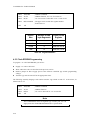
4.5.3 Flash EPROM Programming............................................................................... 4-14
4.6 CONFIGURATION EEPROM............................................................................................ 4-15
4.7 BATTERY BACKED CLOCK ........................................................................................... 4-15
4.8 WATCHDOG TIMER........................................................................................................ 4-15
vi
APPENDICES
APPENDIX A - UTILITIES SOFTWARE ................................................................................ A-1
SCSICOMP - SCSI BLOCK COMPARE UTILITY....................................................... A-2
SCSICOPY - SCSI BLOCK COPY UTILITY ............................................................... A-4
SCSIFMT - SCSI HARD DISK FORMAT UTILITY .................................................... A-6
SCSI-ID - SCSI INITIATOR ID UTILITY ................................................................... A-8
SCSI-VER - SCSI/BIOS VERSION NUMBER UTILITY.............................................. A-9
SERLOAD - SERIAL DOWNLOADING UTILITY ...................................................... A-10
SETUP - CONFIGURATION MEMORY UTILITY ...................................................... A-12
WATCHDOG - WATCHDOG TIMER UTILITY.......................................................... A-25
XTCLK - REAL TIME CLOCK UTILITY ................................................................... A-26
APPENDIX B - BUS TIMING ................................................................................................. B-1
FIGURES
Figure 1-1 Mechanical Dimensions .......................................................................................... 1-4
Figure 1-2 CoreModule/PC and MiniModule Self Stacking Assembly ........................................ 1-5
Figure 1-3 Self Stacking Dimensions........................................................................................ 1-5
Figure 2-1 Connector and Jumper Locations ............................................................................. 2-2
Figure 2-2 Installing a 28-pin Device in a 32-pin Socket........................................................... 2-6
Figure 2-3 Byte-wide Jumper Array Numbering (W1) ............................................................... 2-6
Figure 2-4 Byte-wide Socket S0 EPROM Jumpering ................................................................. 2-8
Figure 2-5 Byte-wide Socket S0 +5 Volt Flash EPROM Jumpering ............................................ 2-8
Figure 2-6 Byte-wide Socket S0 +12 Volt Flash EPROM Jumpering .......................................... 2-9
Figure 2-7 Byte-wide Socket S0 SRAM Jumpering.................................................................... 2-9
Figure 4-1 CoreModule/PC Block Diagram............................................................................... 4-3
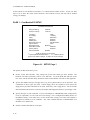
Figure A-1 SETUP Page 1 ....................................................................................................... A-14
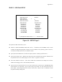
Figure A-2 SETUP Page 2 ....................................................................................................... A-17
Figure A-3 SETUP Page 3 ....................................................................................................... A-21
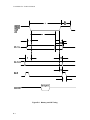
Figure B-1 Memory and I/O Timing......................................................................................... B-2
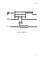
Figure B-2 IOCHRDY Timing ................................................................................................. B-3
vii
CoreModule/PC Technical Manual
TABLES
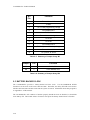
Table 2-1 Connector Usage Summary...................................................................................... 2-1
Table 2-2 Configuration Jumper Summary .............................................................................. 2-3
Table 2-3 Configuration Memory Options ............................................................................... 2-4
Table 2-4 Power Connector (J5) ............................................................................................... 2-5
Table 2-5 Summary of Jumper Array W1.................................................................................. 2-10
Table 2-6 Summary of Jumper Array W2.................................................................................. 2-10
Table 2-7 Utility Connector (J4)............................................................................................... 2-12
Table 2-8 J4 Mating Connectors............................................................................................... 2-13
Table 2-9 Keyboard DIN Connector Pinouts ............................................................................. 2-13
Table 2-10 Parallel Port Connector (J3).................................................................................... 2-15
Table 2-11 J3 Mating Connectors............................................................................................. 2-15
Table 2-12 J2 Mating Connector ............................................................................................. 2-16
Table 2-13 Serial Port Connector (J2) ...................................................................................... 2-17
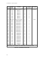
Table 2-14 PC/104 Bus Connector (P1A).................................................................................. 2-18
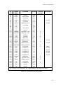
Table 2-15 PC/104 Bus Connector (P1B) .................................................................................. 2-19
Table 2-16 Bus Interrupt Assignments...................................................................................... 2-20
Table 2-17 DMA Channel Assignments.................................................................................... 2-20
Table 3-1 Software-controlled Configuration Options ............................................................... 3-3
Table 3-2 Terminal Cursor Commands..................................................................................... 3-6
Table 3-3 Byte-wide Socket Size and Address Selections........................................................... 3-8
Table 4-1 CoreModule/PC Memory Map .................................................................................. 4-4
Table 4-2 CoreModule/XT I/O Map ......................................................................................... 4-5
Table 4-3 Interrupt Level Assignments..................................................................................... 4-7
Table 4-4 DMA Channel Assignments ..................................................................................... 4-8
Table 4-5 Timer Assignments .................................................................................................. 4-8
Table 4-6 Parallel Port Signal Usage ........................................................................................ 4-11
Table 4-7 Parallel Port Register Bits ........................................................................................ 4-12
Table 4-8 Segment Numbers .................................................................................................... 4-14
Table A-1 SETUP Pages .......................................................................................................... A-13
Table A-2 Byte-wide Socket Size and Address Options ............................................................. A-15
Table A-3 POST Speed Selections............................................................................................ A-15
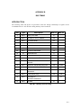
Table B-1 Memory and I/O Timing .......................................................................................... B-1
viii
CHAPTER 1
INTRODUCTION
1.1 GENERAL DESCRIPTION
The CoreModule/PC is an ultra compact, low cost PC compatible computer system combining all the
functionality of a PC motherboard on a 3.6" by 3.8" module. It offers very low power consumption,
+5V only operation, and a wide operating temperature range. Either as a component-like PC
engine, or combined into a system with Ampro's or other compnies’ PC/104-compatible peripheral
modules, the CoreModule/PC is an ideal solution for a variety of embedded and portable
applications.
PC/104 is a mechanical and electrical standard for embedded PCs, and the CoreModule/PC is a
PC/104-compatible CPU module. Ampro offers an extensive line of PC/104 peripheral interfaces,
called MiniModules, that are compatible with the CoreModule/PC. Additionally, there is a growing
number of PC/104-compatible peripheral interfaces from other manufacturers that are compatible
with the CoreModule/PC. The PC/104 Specification and the list of PC/104 vendors and products are
available from the PC/104 Consortium. The Consortium’s address is provided in Chapter 4.
The CoreModule/PC allows system designers to include full PC functionality in their product while
using a minimum of space and power. It uses a CMOS 8088-compatible CPU plus a full
complement of PC compatible DMA controllers, interrupt controllers, and timers. There are either
256 Kbytes or 1 Mbyte of DRAM onboard.
All the features required of a PC compatible embedded controller are included in the
CoreModule/PC. It is equipped with a PC compatible bidirectional parallel port and an 8250
compatible RS232C serial port. The former can be configured as a printer interface or as an 8-bit
general purpose I/O port. A real time clock with a connector for external backup battery is also
included.
Disk drives are often undesirable in embedded applications. Further, the harsh operating
environments in which embedded systems often operate make the use of floppy or hard disk drives
unreliable. A 32-pin socket on the CoreModule/PC allows an onboard byte-wide memory device to
function as a bootable DOS compatible Solid State Disk (SSD). Using Ampro's optional Solid State
Disk Utilities, any DOS-based PC software, including DOS, drivers, and application programs can
reside in an SSD. Ampro's SSD support software can be used with a wide variety of memory
devices, including EPROMs, Flash EPROMs, and NOVRAM modules − up to 1M byte may be
installed. Flash EPROM can be programmed directly on the module.
When ordinary floppy or hard disk drives are required, an Ampro MiniModule/FSS may be mated
directly to the CoreModule/PC. The MiniModule/FSS provides a floppy controller, SCSI interface,
and an additional serial port in the same compact form factor.
1-1
CoreModule/PC Technical Manual
The Award ROM-BIOS used in the CoreModule/PC contains Ampro extensions to support the solid
state disk capability and an optional SCSI interface. A unique "serial console" option allows
external devices connected to the module's serial port to substitute for the standard PC keyboard and
display. Ampro has also added "OEM hooks" to the BIOS to ease the task of system customization,
allowing embedded code to be executed out of ROM installed in the onboard byte-wide sockets or on
an external peripheral adapter. BIOS support for the module’s watchdog timer function is also
included, facilitating easy integration with OEM applications.
The CoreModule/PC has been designed to offer superior configuration flexibility while maintaining
very small overall system dimensions. Its onboard PC/104 bus header provides all the signals found
on the PC bus. Both the CoreModule/PC and Ampro's MiniModule expansion boards are offered
with stackthrough headers, allowing them to be stacked directly on top of each other, thus avoiding
the need for backplanes or card cages. Spacers are used to rigidly mount the boards on top of each
other. In this manner, a complete system consisting of the CoreModule/PC, a MiniModule display
controller, and a MiniModule/FSS (floppy drive, SCSI, and serial port controllers) can be assembled
into a three-high stack measuring only 3.6 x 3.8 x 1.8 inches.
A key advantage of the PC compatibility of the CoreModule/PC is that it runs standard IBM PC
software, including single- and multi-tasking operating systems, languages, development tools, and
thousands of other software applications and utility packages.
1.2 FEATURES
n
n
n
n
n
n
n
n
n
n
n
n
1-2
8088-compatible CMOS processor operating at 9.8 MHz
256 Kbytes or 1 Mbyte of onboard RAM
32-pin byte-wide socket for Solid State Disk support
Industry standard AWARD BIOS with Ampro extensions
DMA, interrupt, and timer controllers
Bidirectional parallel port, serial port, keyboard, and speaker interfaces
Battery backed real time clock
Watchdog timer with BIOS support
Configuration EEPROM eliminates most jumpers
8-bit PC/104 stackthrough bus with 6 mA bus drive
Ultra compact PC/104 form factor (3.6 x 3.8 x 0.6 inches)
Low power consumption: 0.6 W active, 0.3 W sleep
Introduction
1.3 SPECIFICATIONS
CPU and Onboard Memory
n
n
n
9.8 MHz CMOS 8088 integrated CPU
256 Kbytes or 1 Mbytes DRAM onboard
One 32-pin DIP byte-wide memory socket, configurable to:
- 32K
D0000h-D7FFFh, D8000h-DFFFFh, E0000h-E7FFFh , or E8000h-EFFFFh
- 64K
D0000h-DFFFFh or E0000-EFFFFh.
- 128K D0000h-EFFFFh
PC-Compatible Controllers
n
Standard DMA/interrupt/timer support:
- 6 interrupt channels (8259 compatible)
- 3 DMA channels (8237 compatible)
Note
Certain DMA restrictions apply − see Chapter 4, Section 4.3.5.
n
3 programmable counter/timers (8254 compatible)
n
RS232C serial port (COM1):
- 8250 compatible
- Software controlled baud rate
- Full handshaking
- Onboard ±9 Vdc generation
n
Bidirectional parallel printer port
n
Keyboard port (requires PC or XT keyboard)
n
Speaker port with 0.1 watt drive
n
8-bit PC/104 stackthrough bus with 0.6 mA bus drive
Note
Only 10 bits of I/O address space is commonly used on the
PC/104 bus. See discussion in Chapter 4, Section 4.2.4.
Other Onboard Functions
n
1K bit configuration EEPROM, with 512 bits for OEM use
n
Real-time clock. Requires external backup battery (3.0V-3.6V)
n
Watchdog timer function (with BIOS support). Provides “super-NMI” triggered system RESET
1-3
CoreModule/PC Technical Manual
Physical
n
Size: 3.6 x 3.8 x 0.6 inches (90 x 96 x 15 mm)
n
Power requirement (typical): +5V ±5% at 0.6 W active, 0.3 W sleep
n
Multilayer PCB with ground and power planes for low noise
n
Operating environment:
n
0-70° C
n
5-95% relative humidity (non-condensing)
n
Storage Temperature: -55° to +85° C
n
Weight: 2.4 oz. (68 gm)
Note: The dark colored squares indicate pin 1
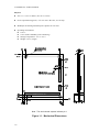
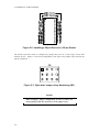
Figure 1-1. Mechanical Dimensions
1-4
Introduction
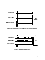
Figure 1-2. CoreModule/PC and MiniModule Self Stacking Assembly
Figure 1-3. Self Stacking Dimensions
1-5
CHAPTER 2
HARDWARE CONFIGURATION
2.1 INTRODUCTION
This chapter describes the requirements to integrate the CoreModule/PC as a component within a
wide variety of applications including embedded systems. Information is provided regarding
connector signals and pinouts, external device requirements, interconnection cable wiring, and
board configuration. Also covered in this chapter are the configuration and initialization
requirements of standard and optional onboard devices. Unique to the CoreModule/PC is provision
of a SETUP function, similar to that found in PC/AT's, to store system parameters in a nonvolatile
configuration memory, rather than using jumpers and switches.
Many of the board's functions are software controlled rather than hardware controlled. Therefore,
many features and functions described in this manual assume the presence of the board's standard
ROM-BIOS for their operation. Refer to Chapter 3 for typical software configuration information,
and to Chapter 4 for technical details regarding the board's hardware and software functions.
2.1.1 Interface Connectors
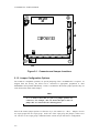
Figure 2-1 shows the location of the board's interface connectors (P1, J2-J5) and configuration
jumper locations. Table 2-1 summarizes the use of each of the board's connectors. Connector
pinouts and signal definitions are provided in the sections of this chapter that cover each connector
interface.
Connector
Function
Size
P1
PC Expansion Bus
64-pin
J2
Serial Port
10-pin
J3
Parallel Port
26-pin
J4
Utility/Keyboard
10-pin
J5
Power
8-pin
Table 2-1. Connector Usage Summary
The board's I/O connectors consist of dual-row male header connectors. These connectors can be
mated with female header connectors of flat ribbon (IDC) cables, or with discretely wired
connectors.
2-1
CoreModule/PC Technical Manual
Figure 2-1. Connector and Jumper Locations
2.1.2 Jumper Configuration Options
For normal PC compatible operation, no special jumpering of the CoreModule/PC is required. As
shipped from the factory, the board can be connected to appropriate peripherals or other
MiniModules and operated immediately. Table 2-2 summarizes the board's jumper options; they are
each discussed in detail in this chapter.
Note
A "/" is used to show that two pins of a jumper position are
connected. For example, "W1-3/4" means that pins 3 and 4 of
jumper W1 are connected with a shorting block.
Each of the board's jumper options is referred to by a "W" number (i.e. "W1"). Jumpers occur in
two 2-pin groups and one 12-pin group. In the case of the 2-pin group, the jumper is either on or
off. The use of the 12-pin group is illustrated in the section on byte-wide device configuration.
2-2
Hardware Configuration
Note
The option jumpering pins on the CoreModule/PC are on 2mm
centers. It is necessary to use compatible 2mm shorting blocks
when setting the jumper options.
Two sources for 2mm shorting blocks are:
Berg
Barley Mill Plaza
P. O. Box 80013,
Wilmington, DE 19880-0013
Phone: (800) 237-4357
2mm shorting blocks: P/N 86730-001
Hirose Electric U.S.A., Inc.
2685-C Park Center Drive,
Simi Valley, CA 93065
Phone: (805) 522-7958
2mm shorting blocks: P/N A3-SP
Jumper
Function
W1
Configuration for byte-wide socket S0
W2
Configuration for byte-wide socket S0
W4
12V flash programming power
Table 2-2. Configuration Jumper Summary
2.1.3 Configuration Memory Options
In addition to the various configuration jumper options, there are a number of system configuration
parameters which are initialized by the ROM-BIOS based on the contents of a unique 1024 bit
configuration EEPROM.
This device will be referred to as the board's nonvolatile Configuration Memory. Through the use of
this Configuration Memory function, the number of jumper configuration options has been
minimized, and board setup has been simplified. This memory includes 512 bits accessible to the
BIOS and used by Ampro for SETUP, and 512 bits available to the OEM. Refer to Chapter 4 for a
discussion on how to access this user area.
2-3
CoreModule/PC Technical Manual
The SETUP function within the ROM-BIOS can be accessed either with a "hot-key" entry (CTRLALT-ESC) during POST or through the SETUP program provided on the CoreModule/PC Utilities
Diskette. The SETUP function is used to specify all of the configuration parameters stored in the
board's nonvolatile Configuration Memory.
Table 2-3 lists the main functions which are controlled by the contents of the nonvolatile
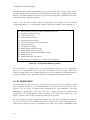
Configuration Memory. Use of the SETUP function is discussed in Chapter 3 and in Appendix A.
n
n
n
n
n
n
n
n
n
n
n
n
n
n
Date and Time values of the battery-backed real time clock
Floppy drive quantity and type
Video controller type
Enable/disable serial port
Enable/disable parallel port
Set 32-pin byte-wide socket configurations
POST Speed Option
Watchdog timer options
Enable/disable serial boot loader
Enable/disable SETUP's "hot-key"
Enable/disable Ampro Extended BIOS services
Default boot drive
SCSI hard disk drive parameters
Console input and output device selection and configuration
Table 2-3. Configuration Memory Options
The CoreModule/PC is shipped with a set of preprogrammed selections. If the Configuration
Memory is ever programmed in such a way that it is impossible to boot or regain control of the
system, a shorting block can be installed temporarily on J2-7/8 to defeat the Configuration Memory
and use the defaults instead. The system can then be reconfigured using the SETUP function.
2.2 DC POWER INPUT
The CoreModule/PC requires only +5V (±5%) for normal operation. The ±9V for RS232C (serial
port) is generated onboard. If a 12 volt Flash EPROM is to be programmed in the byte-wide socket,
typically +12V at 30 mA is required while programming the Flash EPROMs. Check the
manufacturer's specifications for the device you use. (Jumper W4 must be installed when
programming +12V Flash EPROMs.) Power is supplied via the 8-pin Power Connector J5. See
Figure 2-1 for the location of this connector and Table 2-4 for its pinout.
The power requirements of the CoreModule/PC depend on several factors, including what functions
are present on the board (e.g. DRAM and byte-wide memory devices), and what peripherals are
connected to the board's I/O ports (e.g. keyboard) or bus header. For example, a MiniModule video
2-4
Hardware Configuration
controller installed on the board's MiniModule header would draw its power through the
CoreModule/PC's power connector.
A fully populated CoreModule/PC (without a keyboard, serial or parallel peripheral, or MiniModule
installed) requires approximately 0.6 watts of power (115 mA).
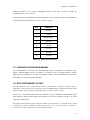
Pin
Function
1
Ground
2
+5 V DC
3
No pin (KEY)
4
+12V DC
5
-5V DC
6
-12V DC
7
Ground
8
+5V DC
Table 2-4. Power Connector (J5)
2.3 ONBOARD SYSTEM DRAM MEMORY
The CoreModule/PC is offered in two onboard DRAM memory configurations: 256 KBytes, and 1
Mbyte. With 256 KBytes present, 192 KBytes is available for use by programs and data. With 1
MByte present, 640 KBytes is available for programs and data. The CoreModule/PC does not offer
EMS support for memory beyond 640 KBytes.
2.4 BYTE-WIDE MEMORY SOCKET
The CoreModule/PC has a single onboard socket for the addition of byte-wide memory devices,
labeled S0. A byte-wide device is a memory, such as an EPROM, that is organized to provide 8 bits
of parallel data. Devices used in S0 must have an access time of 250 nS or less.
Socket S0 is a 32-pin DIP socket that can accommodate a variety of EPROM, Flash EPROM, Static
RAM (SRAM), and nonvolatile RAM (NOVRAM) devices, useful for program storage or as "Solid
State Disk" (SSD) drives.
The jumper options for S0 can also support a number of 28-pin devices. If a 28-pin device is used
in socket S0, it must be installed such that socket pins 1, 2, 31, and 32 are unused. Figure 2-2
shows how to install a 28-pin device in the 32-pin DIP socket.
2-5
CoreModule/PC Technical Manual
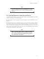
Figure 2-2. Installing a 28-pin Device in a 32-pin Socket
The board's byte-wide socket is configured by jumper array W1 for a wide range of byte-wide
memory devices. Figure 2-3 shows the arrangement of the pins in the jumper array and how the
pins are numbered.
Figure 2-3. Byte-wide Jumper Array Numbering (W1)
Caution
When changing a jumper configuration, be sure to remove any
unused jumpers that may already be on the jumper array.
2-6
Hardware Configuration
Note
The option jumpering pins on the CoreModule/PC are on 2mm
centers. See Section 2.1.2 for sources of shorting blocks for
these pins.
2.4.1 Jumpering Diagrams for Popular Byte-wide Devices
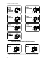
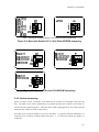
Configuration jumper settings for popular NOVRAMs, EPROMs, and Flash EPROMs are provided
in Figures 2-4 through 2-7 on the following pages.
Be sure to supply +12V power to the board if you plan to program +12V Flash EPROMs in situ (see
Section 2.2).
In addition to having its device configuration jumpers set, each socket must be enabled or disabled
via a parameter within the board's nonvolatile Configuration Memory. The Ampro SETUP function
offers a convenient means to do this. SETUP resides in the ROM-BIOS and can be accessed either
with a "hot-key" entry (CTRL-ALT-ESC) just prior to boot time or through the SETUP program
provided on the CoreModule/PC Utilities Diskette.
Note
When a byte-wide memory socket is enabled, its memory
address space is unavailable for use by other devices on the PC
bus. A byte-wide socket must be "disabled" before its memory
space can be used for other purposes.
2-7
CoreModule/PC Technical Manual
Figure 2-4. Byte-wide Socket S0 EPROM Jumpering
Figure 2-5. Byte-wide Socket S0 +5 Volt Flash EPROM Jumpering
2-8
Hardware Configuration
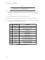
Note: W4 must be installed during +12V Flash EPROM Programming
Figure 2-6. Byte-wide Socket S0 +12 Volt Flash EPROM Jumpering
Figure 2-7. Byte-wide Socket S0 NOVRAM Jumpering
2.4.2 Custom Jumpering
Tables 2-5 and 2-6 show a summary of the functions for each pin of each jumper array (W1 and
W2). The tables can be used to determine how to jumper the byte-wide socket for devices that are
not shown in the jumpering figures. The tables show which signal appears on each jumper pin and
what pins they connect to on the 32-pin socket.
Note that 32-pin socket pin numbers are given in the tables. To properly interpret numbering for a
28-pin device in socket S0, remember that socket pins 1, 2, 31, and 32 are unused (See Figure 2-2
for details).
2-9
CoreModule/PC Technical Manual
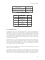
W1
Pin
Function
1
From address A18
2
To S0-1
3
+12 V Flash programming voltage
4
From address A17
5
To S0-31
6
From write enable signal
7
To S0-29
8
To S0-30
9
From address A15
10
To S0-3 (has a 10K ohm pull-up)
11
From address A14
12
+5 V power; to S0-32
Table 2-5. Summary of Jumper Array W1
Jumper
Pin
Function
W2
1
W1-2; S0-1
W2
2
From address A19
Table 2-6. Summary of Jumper Array W2
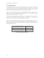
2.5 BATTERY-BACKED CLOCK
The CoreModule/PC provides a battery-backed real time clock. Use the ROM-BIOS SETUP
function to set the clock to the correct time and date. Thereafter, the utility XTCLK can be used to
initialize the DOS time and date each time the system is booted. Information about this program is
in Appendix A of this manual.
The CoreModule/PC will continue to function properly should the clock be disabled, or should the
clock battery fail. The normal "DOS" clock does not require the battery-backed clock to function.
2-10
Hardware Configuration
Note
A back-up battery is not needed for storage of the
Configuration Memory parameters.
The real time clock can be backed up with a 3.6V Lithium battery. The Tadiran TL-5242/W is
recommended. It is available from Tadiran Electronic Industries. The backup battery is connected
between J4 pin 9 (+BATV) and J4 pin 2 (-BATV) of the Utility Connector (J4).
2.6 WATCHDOG TIMER
The watchdog timer can be used to trigger a “super-NMI” interrupt, resulting in a system reset,
when it "times out". It is often used at boot time to monitor the boot process. It can also be used to
monitor the activity of an application program. If the application program does not reset the
watchdog timer periodically (because of a malfunction), the watchdog timer will generate a system
reset. To find out more about using the watchdog timer, refer to Chapter 4.
The boot time monitor function is configured in SETUP. This is discussed in Chapter 3. The
application program monitor function must be written into the application. This is discussed in
Chapter 4. In some simple applications, the WATCHDOG program provided on the utility diskette
can be used to retrigger the watchdog timer. Use of the WATCHDOG program is discussed in
Appendix A.
2.7 PERIPHERAL INTERFACE CONFIGURATION AND CONNECTIONS
This section covers the requirements of the board's external device interface connectors.
Information is provided on interface and device characteristics, connector pinouts, signal
definitions, jumper configuration, and nonvolatile Configuration Memory setup.
2.7.1 Utility Connector (J4)
A single 10-pin header connector (J4) provides connections for four functions: speaker, reset,
keyboard, and a "power good" signal. The pinout and signal definitions of the Utility Connector are
shown in Table 2-7. Table 2-8 gives the mating connectors for J4. Here are some considerations
regarding the signals on this connector:
n
The speaker signal is buffered by a transistor amplifier to provide approximately .1 watt of
audio power to an external speaker. Typically, a small general purpose 2 or 3 inch diameter
permanent magnet speaker with an 8 ohm voice coil is used.
n
A PC compatible keyboard can be connected to the board's keyboard port via connector J4.
Often, keyboards are connected with a 5-pin DIN connector. For convenience, Table 2-9 also
shows the connections for a 5-pin DIN type keyboard connector.
2-11
CoreModule/PC Technical Manual
Note
"AT" keyboards are not compatible with "PC" or "XT"
keyboards, and may not be used with this interface.
n
An LED lamp can be connected between J4 pins 8 (+5 Vdc) and 7 (Ground) to provide a poweron indication. An external series current limiting resistor is required for some LEDs (typically
330 ohms).
n
A reset pushbutton switch can be connected between J4 pins 3 and 7.
n
The real time clock battery, if used, connects between J4 pins 9 (+BATV) and 2 (-BATV).
n
If a system power status signal is available, it should be connected to J4 pin 10. A high-true
TTL level signal is required. A low resets the computer.
Pin
Signal Name
Function
1
Speaker+
Audio signal through 33 ohm series resistor
2
-BATV
Backup battery connection
3
Reset Switch
Reset control
4
N/C
No connection
5
Kbd Data
Keyboard data
6
Kbd Clk
Keyboard clock
7
Kbd Gnd
Ground for keyboard and LED
8
Kbd Pwr
+5 V for keyboard and LED
9
+BATV
Backup battery connection
10
Power Good
True when power is good
Table 2-7. Utility Connector (J4)
2-12
Hardware Configuration
Ribbon Connector
3M 3473-7010
Discrete Wire Connector Housing
Molex 22-55-2101
Discrete Wire Connector Pins
Molex 16-02-0103
Table 2-8. J4 Mating Connectors
DIN Pin
Signal Name
J4 Pin
1
Keyboard Clock
6
2
Keyboard Data
5
3
N/C
-
4
Ground
7
5
Keyboard Power
8
Table 2-9. Keyboard DIN Connector Pinouts
2.7.2 Parallel Port (J3)
The parallel port can be used as a standard PC printer port, or it can be used for general purpose
programmable I/O. The data lines are truly bidirectional. The control lines are quasi-bidirectional.
This is discussed in Chapter 4. By using the port's input and output handshake signals, along with
its 8-bit bidirectional data lines, many types of interfaces for specialized devices can be created,
including writing data to LCD display panels, scanning keyboards, etc. Refer to Chapter 3 for
typical system software configuration information, and to Chapter 4 for hardware details regarding
nonstandard uses of this interface.
The parallel port is set to extended mode (bidirectional) at POST time. When configured in this
manner, it can be used to support a standard printer, but there is some danger of old or improperly
written software inadvertently changing the direction control bit in the parallel port control register.
If this could be a problem in your installation, use the port in its AT-mode setting. Refer to Section
4.4 for instructions on how to set the parallel port mode.
When enabled in SETUP, the parallel port is configured as the primary parallel port, at I/O address
378h-37Ah. There are no jumpers to set.
It is possible to configure a system with more than one parallel port. Using an Ampro
MiniModule/SSP (serial, serial, parallel) you can add two additional serial ports and an additional
parallel port to the CoreModule/PC. When more than one parallel port is present in a system, the
names LPT1, LPT2, etc. are assigned during system initialization. The ROM-BIOS scans for
2-13
CoreModule/PC Technical Manual
parallel ports in the system and assigns LPT1 to the first one found. Therefore, a parallel port can
be LPT1 regardless of address.
Usually a different "LPT" has a different "IRQ" (hardware interrupt) assigned to it. The IRQ
assigned to the parallel port on the CoreModule/PC is IRQ7. It cannot be changed. Hardly any
software (including DOS) uses interrupts for parallel printers. When the system is powered up, this
interrupt comes up disabled so it can be used by other bus devices if required.
The parallel printer connector (J3) is a 26-pin male header connector. Table 2-10 gives the
connector's pinout and signal definitions. Table 2-11 gives the mating connectors for J3. Be sure
not to exceed 10 feet of total cable length between the board's connector and the printer. Beyond
this distance, the signal cannot be expected to be reliable due to the limitations of the port's signal
drivers.
2-14
Hardware Configuration
J3 Pin
Signal
Name
Typical Function
In/Out
DB25
Pin
1
-STB
Output Data Strobe
Out
1
3
PD0
Parallel Data Bit 0
I/O
2
5
PD1
Parallel Data Bit 1
I/O
3
7
PD2
Parallel Data Bit 2
I/O
4
9
PD3
Parallel Data Bit 3
I/O
5
11
PD4
Parallel Data Bit 4
I/O
6
13
PD5
Parallel Data Bit 5
I/O
7
15
PD6
Parallel Data Bit 6
I/O
8
17
PD7
Parallel Data Bit 7
I/O
9
19
-ACK
Character Accepted
In
10
21
BSY
Printer Busy
In
11
23
PE
Paper Empty
Out
12
25
SLCT
Printer Selected
Out
13
2
-AFD
Autofeed
Out
14
4
-ERR
Printer Error
In
15
6
-INIT
Init Printer
Out
16
8
-SLIN
Select Printer
Out
17
26
N/C
KEY
--
--
Ground
Signal Ground
--
18-25
10, 12
14, 16
18, 20
22, 24
Table 2-10. Parallel Port Connector (J3)
IDC Ribbon Connector
3M 3399-7026
Discrete Wire Connector Housing
Molex 22-55-2261
Discrete Wire Connector Pins
Molex 16-02-0103
Table 2-11. J3 Mating Connectors
2-15
CoreModule/PC Technical Manual
2.7.3 Serial Port (J2)
The CoreModule/PC features an onboard PC-compatible RS232C serial port which can be enabled
or disabled in SETUP. The module’s serial port, which appears on connector J2, is normally
accessed as COM1. The pinout of the serial port connector (J2) is arranged so that a simple flat
ribbon cable with an IDC DB9 connector provides a PC-compatible connection.
Many devices, such as printers and modems, require handshaking in one or both directions to work
properly. Consult the documentation on the external serial device for information regarding
possible handshake and other interface considerations.
A useful feature of the ROM-BIOS is that it allows a device connected to the board's serial port to be
used as the system "console" (keyboard and display), as an alternative to the regular video
controller, monitor, and keyboard. This is further discussed in Chapter 3.
Table 2-13 gives the signal pinout for the board’s 10-pin serial port male header connector. For
reference, the table includes the DB9 and DB25 connector pinouts which correspond to the "PC
standard" for serial ports. Table 2-12 gives some examples for the mating connector you would use
for making connecting cables.
IDC Ribbon Cable Connector
3M 3475-7010
Discrete Wire Connector Housing
Molex 22-55-2101
Discrete Wire Connector Pins
Molex 16-02-0103
Table 2-12. J2 Mating Connectors
2-16
Hardware Configuration
J2 Pin
Signal
Name
Function
In/Out
DB9M
Pin
DB25M
Pin
1
DCD
Data Carrier Detect
In
1
8
2
DSR
Data Set Ready
In
6
6
3
RXD
Receive Data
In
2
3
4
RTS
Request To Send
Out
7
4
5
TXD
Transmit Data
Out
3
2
6
CTS
Clear To Send
In
8
5
7
DTR
Data Terminal Ready
Out
4
20
8
RI
Ring Indicator
In
9
22
9
GND
Ground
---
5
7
10
---
Key Pin
---
---
---
Table 2-13. Serial Port Connector (J2)
2.8 PC/104 EXPANSION BUS
The PC/104 expansion bus connector on the CoreModule/PC is a 64-pin dual-row female header on
the top of the module, and the corresponding male pins on the bottom of the module. It is
designated P1.
This stackthrough connector allows great flexibility in connecting the
CoreModule/PC to ribbon cables, fixed connectors, or to peripheral cards in various stacking
arrangements.
The PC/104 expansion bus provides 6 mA of bus drive, which is capable of driving 10 LSTTL bus
loads. Further information about these signals is provided in Chapter 4.
The board's expansion bus pins are designated in accordance with the PC/104 specification. Tables
2-14 and 2-15 show the pinout and functions of the signals on the expansion bus.
2-17
CoreModule/PC Technical Manual
P1
Pin
Signal
Name
Function
In/Out
Current
(in mA)
A1
-IO CHCHK
Memory Parity Err
IN
A2
SD7
Data Bit 7
I/O
6
A3
SD6
Data Bit 6
I/O
6
A4
SD5
Data Bit 5
I/O
6
A5
SD4
Data Bit 4
I/O
6
A6
SD3
Data Bit 3
I/O
6
A7
SD2
Data Bit 2
I/O
6
A8
SD1
Data Bit 1
I/O
6
A9
SD0
Data Bit 0
I/O
6
A10
I/O CRDY
I/O Channel Ready
IN
A11
AEN
Address Enable
I/O
6
A12
SA19
Address Bit 19
I/O
6
A13
SA18
Address Bit 18
I/O
6
A14
SA17
Address Bit 17
I/O
6
A15
SA16
Address Bit 16
I/O
6
A16
SA15
Address Bit 15
I/O
6
A17
SA14
Address Bit 14
I/O
6
A18
SA13
Address Bit 13
I/O
6
A19
SA12
Address Bit 12
I/O
6
A20
SA11
Address Bit 11
I/O
6
A21
SA10
Address Bit 10
I/O
6
A22
SA9
Address Bit 9
I/O
6
A23
SA8
Address Bit 8
I/O
6
A24
SA7
Address Bit 7
I/O
6
A25
SA6
Address Bit 6
I/O
6
A26
SA5
Address Bit 5
I/O
6
A27
SA4
Address Bit 4
I/O
6
A28
SA3
Address Bit 3
I/O
6
A29
SA2
Address Bit 2
I/O
6
A30
SA1
Address Bit 1
I/O
6
A31
SA0
Address Bit 0
I/O
6
A32
GND
Ground
N/A
PU/PD/Ser
*
4.7K PU
1K PU
* PU = Pull Up; PD = Pull Down; Ser = Series resistor. All values are in ohms.
Table 2-14. PC/104 Bus Connector (P1A).
2-18
Hardware Configuration
P1
Pin
Signal
Name
Function
In/Out
B1
GND
Ground
N/A
B2
RESET
System Reset
OUT
B3
+5V
+5v Power
N/A
B4
IRQ2
Int Request 2
IN
B5
-5V
-5V Power
N/A
B6
DRQ2
DMA Request 2
IN
B7
-12V
-12V Power
N/A
B8
N/A
B9
+12V
Current
(in mA)
PU/PD/Ser
*
6
27K PU
27K PD
N/A
+12V Power
N/A
B10
N/A
Key Pin
N/A
B11
-SMEMW
Mem Wrt, lo 1M
I/O
6
B12
-SMEMR
Mem Rd, lo 1M
I/O
6
B13
-IOW
I/O Write
I/O
6
B14
-IOR
I/O Read
I/O
6
B15
-DACK3
DMA Ack 3
OUT
6
B16
DRQ3
DMA Request 3
IN
B17
-DACK1
DMA Ack 1
OUT
B18
DRQ1
DMA Request 1
IN
B19
-REFRESH
Memory Refresh
I/O
6
B20
CLK
CPU Clock
OUT
6
B21
IRQ7
Int Request 7
IN
27K PU
B22
IRQ6
Int Request 6
IN
27K PU
B23
IRQ5
Int Request 5
IN
27K PU
B24
IRQ4
Int Request 4
IN
27K PU
B25
IRQ3
Int Request 3
IN
27K PU
B26
-DACK2
DMA Ack 2
OUT
6
B27
T/C
Terminal Count
OUT
6
B28
BALE
Addrs Latch En
OUT
6
B29
+5V
+5V Power
N/A
B30
OSC
14.3MHz Clk
OUT
B31
GND
Ground
N/A
B32
GND
Ground
N/A
27K PD
6
27K PD
33 Ser
6
* PU = Pull Up; PD = Pull Down; Ser = Series resistor. All values are in ohms.
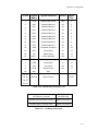
Table 2-15. PC/104 Bus Connector (P1B)
2-19
CoreModule/PC Technical Manual
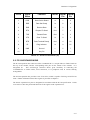
The PC expansion bus provides a number of interrupt and DMA control signals. When you
interface the CoreModule/PC to other MiniModules, PC bus plug-in cards, or other logic that
requires either interrupt or DMA support, you must select which channels of these functions will be
used by the added functions. This is typically done using either switches or configuration jumpers
on a plug-in card. Check that you do not configure the added card to use an interrupt or DMA
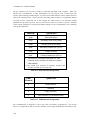
channel that is already being used! For your convenience, Tables 2-16 and 2-17 provide a summary
of the normal assignment of interrupt and DMA channels on the CoreModule/PC and commonly
used expansion modules.
∗
Interrupt
Typical Use
IRQ2
EGA/VGA Option*
IRQ3
Secondary Serial Port (COM2)
IRQ4
Primary Serial Port (COM1)
IRQ5
Secondary Parallel Port (LPT2)**
IRQ6
Floppy Controller
IRQ7
Primary Parallel Port (LPT1)**
This interrupt is sometimes assigned to a VGA
controller, but is normally not required on Ampro
VGA adapters.
∗∗ The printer port interrupt is normally disabled and
available for other devices on the bus.
Table 2-16. Bus Interrupt Assignments
DMA
Channel
Typical Use
0
DRAM Refresh
1
Available
2
Floppy controller
3
SCSI controller (on MiniModule/FSS)
Table 2-17. DMA Channel Assignments
The CoreModule/PC is designed to offer a great deal of flexibility of applications. One obvious
choice is to expand the system as necessary with the various Ampro MiniModules and other PC/104-
2-20
Hardware Configuration
compatible modules. Another option is to expand the system using the Ampro MiniBackplane and
various conventional PC expansion boards. Still another option is to configure a dedicated OEM
logic board with the desired peripheral components and simply install the CoreModule as the
computing engine. These options are discussed in detail in the next section.
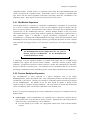
2.8.1 MiniModule Expansion
In many applications it is necessary to expand the CoreModule/PC's capabilities by incorporating
one or more of Ampro's MiniModules or other PC/104-compatible expansion modules into the
device or system of interest. All such modules can be directly connected to the CoreModule/PC's PC
expansion bus via the stackthrough connector. Stacking multiple modules in this way allows
considerable flexibility in system design without requiring any motherboards, expansion slots, or
other hardware. Figure 1-2 illustrates a typical self-stacking configuration in which a
CoreModule/PC is combined with a MiniModule/FSS (for floppy, serial, and SCSI interfaces) and a
MiniModule/VGA-FP (for flat panel display interface) providing the equivalent of an XT computer
with a hard disk and floppy interfaces, two serial ports, a parallel port, and VGA flat panel display
output.
Note
The MiniModule/FSS must be jumpered for the ‘TC’ option to
function with the CoreModule/PC. See the MiniModule/FSS
Technical Manual for details.
A wide range of PC/104 expansion modules is available from Ampro and over a hundred other
companies that support the PC/104 module standard. Functions available include display
controllers, serial/parallel expansion, network interfaces, modem and communications controllers,
analog I/O interfaces, and many more. For information on PC/104 modules that may be useful in
developing CoreModule/PC-based embedded systems, contact Ampro and the PC/104 Consortium.
2.8.2 Passive Backplane Expansion
The CoreModule/PC is easily connected to a passive backplane, such as the Ampro
MiniBackplane/PC, with a short ribbon cable. This configuration produces a modular equivalent of
a standard PC or XT chassis. Virtually any existing PC-compatible expansion board can be plugged
into the MiniBackplane. The module's 6 mA bus drive should be capable of driving several
expansion cards on a properly designed backplane. The exact number of boards and modules that
can be used depends on the current drain requirements of the modules used.
Here are several points regarding the use of the CoreModule/PC with a passive backplane for the PC
Expansion Bus:
n
Cable Length -- If the CoreModule/PC's PC expansion bus is connected to expansion devices
with a ribbon cable, keep the cable as short as possible. Expansion bus cables longer than six
inches can reduce system reliability. We recommend:
n
For cable lengths up to 6 inches, use a high quality ribbon cable, such as 3M part number
3365/64.
2-21
CoreModule/PC Technical Manual
n
n
For cable length between 6 and 12 inches, use a high quality ribbon cable with a ground
plane, such as 3M part number 3353/64.
Cable lengths greater than 12 inches are not recommended.
n
Backplane Quality -- Be sure to use a high quality backplane having minimal signal crosstalk.
Use of power and ground planes and guard traces between bus signals are recommended.
n
Termination -- If bus termination is required, use "AC" rather then "DC" (resistive)
termination. Placing 100 ohms in series with 100 pf between each signal and ground is
recommended. Do not use resistive termination.
n
Reset and TC Deglitching -- Some expansion cards have asynchronous TTL inputs especially
vulnerable to noise and crosstalk. The active high RESET and TC lines are ones to watch out
for. If these signals are susceptible, a 200 pf to 500 pf capacitor connected between the signal
and ground can be used to prevent false resets. These RESET and TC deglitching capacitors are
included on the Ampro MiniBackplanes.
2-22
CHAPTER 3
SOFTWARE CONFIGURATION
3.1 INTRODUCTION
The CoreModule/PC supports a wide variety of configuration options. This chapter provides an
overview of the system features and configuration options that are available through software
configuration. A combination of standard DOS and Ampro-supplied utilities and drivers allows you
to create a highly customized system based on the CoreModule/PC. This chapter provides a brief
discussion of how to use the available software utilities to configure a system for many typical
installations.
Assuming you have connected the CoreModule/PC to a keyboard, a display (via a MiniModule
display controller), and a floppy drive (via a MiniModule/FSS) as described in Chapter 2, you
should have no difficulty booting the system under DOS. You will probably want to take advantage
of the flexibility designed into the CoreModule/PC ROM-BIOS and utilities software to create a
customized installation. You can tailor your software configuration to a wide variety of hardware
configurations, as indicated in Chapter 2.
Some familiarity with "DOS" (PC-DOS, MS-DOS, or DR DOS) is assumed. Please refer to the
appropriate IBM, Microsoft, or Digital Research reference manuals for further information on the
use of the DOS operating system and its drivers and utilities. In addition, Appendix A of this
manual contains a detailed description of each Ampro CoreModule/PC utility program.
3.2 OPERATION WITH DOS
The CoreModule/PC and its ROM-BIOS have been designed to allow the use of IBM PC-DOS,
Microsoft MS-DOS, or Novell DR DOS, Versions 2.x or higher. Throughout this chapter, the term
"DOS" will be used to refer to any of these operating systems, except in cases where a difference in
operation exists.
Caution
Many variations of MS-DOS exist which have been customized
for operation on specific computer systems. These cannot be
expected to function properly on the CoreModule/PC and
should not be used. Use "IBM PC-DOS," or use the "generic
IBM compatible" version of MS-DOS supplied directly by
Microsoft on an OEM basis, if you do not choose to use the DR
DOS operating system supplied by Ampro.
When used with DOS, the standard PC devices are available, including keyboard port, speaker port,
parallel printer port, serial port, programmable timer, DMA controller, and interrupt controller.
3-1
CoreModule/PC Technical Manual
Addition of the MiniModule/FSS adds support for floppy and hard disks and another serial port. In
addition, the optional Ampro display controller MiniModules support the most popular PCcompatible video modes: VGA, CGA, MDA, and Hercules monochrome graphics on CRTs, or on
LCD, plasma, or electroluminescent (EL) flat panel displays.
The DOS and ROM-BIOS time-of-day clocks are supported in the usual manner. They can be
initialized at boot time manually by the TIME and DATE DOS commands, or they can be initialized
automatically during execution of the AUTOEXEC.BAT by using an Ampro-supplied utility,
XTCLK.COM, assuming the onboard real time clock is supplied with battery power as described in
Chapter 2. Use of the XTCLK.COM program is described in Appendix A.
If a MiniModule/FSS is used for a disk interface, floppy and hard disk usage is partly dependent on
which DOS version is used:
n
DOS version 3.0 (or later) is required for operation with 1.2 megabyte drives.
n
DOS version 3.2 (or later) is required for operation with 80-track (720K) microfloppy drives.
n
DOS version 3.3 (or later) is needed for use with 1.44 megabyte microfloppies, and with the
optional Ampro Solid State Disk support utilities.
n
DOS version 2.1 (or later) is required for SCSI hard disk usage under the board's ROM-BIOS
and SCSI support software.
n
Support for hard disks larger than 32 megabytes is available under DR DOS version 3.4 (or
later), or under MS-DOS or PC-DOS versions 4.0 (or later).
3.3 AMPRO SETUP AND UTILITIES
A high degree of system configurability is available through options provided by: (1) the Ampro
SETUP function; (2) the CoreModule/PC Utilities.
3.3.1 The Ampro SETUP Function
The Ampro SETUP function is used to initialize or modify the contents of the board's non-volatile
Configuration Memory, i.e. the configuration EEPROM device.
Note
Any changes made in the contents of the Configuration
Memory do not take effect until the system reboots.
3-2
Software Configuration
Note
If the Configuration Memory is ever configured to a state that
makes it impossible to regain control of the system, a shorting
block can be installed temporarily on J2-7/8 to defeat the
Configuration Memory and use defaults that are in the ROMBIOS. One can then use the "hot-key" (CTL-ALT-DEL) to
activate SETUP and reprogram the Configuration Memory.
The shorting block on J2-7/8 must be removed for the
Configuration Memory to have an effect.
The configuration options controlled by SETUP are given in Table 3-1. Examples of how a typical
system can be configured for many of these options are given later in this chapter.
n
n
n
n
n
n
n
n
n
n
n
n
n
n
Date and Time values of the battery-backed real time clock
Floppy drive quantity and type
Video controller type
Enable/disable serial port
Enable/disable parallel port
Set 32-pin byte-wide socket configurations
POST Speed Option
Watchdog timer options
Enable/disable serial boot loader
Enable/disable SETUP's "hot-key"
Enable/disable Ampro Extended BIOS services
Default boot drive
SCSI hard disk drive parameters
Console input and output device selection and configuration
Table 3-1. Software-controlled Configuration Options
The SETUP function is contained directly within the ROM-BIOS. This allows access to all
configuration parameters by using the "CTL-ALT-ESC" key sequence at powerup or reset time. As
a convenience, a SETUP utility, executable from the DOS command line, provides entry into the
ROM-BIOS SETUP function at any time during system operation. The SETUP utility also allows
you to save Configuration Memory contents to a disk file. The disk file can be used later to set the
Configuration Memory in the same system or another CoreModule/PC system. Refer to Appendix A
for a detailed list of the system parameters controlled by SETUP and how to use the program.
3-3
CoreModule/PC Technical Manual
3.3.2 CoreModule/PC Utilities Overview
The following programs are contained on the CoreModule/PC Utilities Diskette. (Actual utility
names and descriptions may change, in which case appropriate "DOC" files are included on the
utilities diskette to explain the changes.) Each of these programs is described in Appendix A of this
manual. Note that use of the SCSI utilities requires the addition of a MiniModule/FSS (or
equivalent).
n
SCSICOMP - A SCSI utility that lets you compare the contents of two direct access SCSI
devices (such as hard disks).
n
SCSICOPY - A SCSI copy utility that allows you to copy blocks of data between two direct
access SCSI devices (such as hard disks).
n
SCSIFMT - A SCSI hard disk formatter.
n
SCSI-ID - Reports the system's SCSI initiator ID.
n
SCSI-VER - Returns the Ampro SCSI/BIOS version number.
n
SERLOAD -- A serial loader utility allowing a host system to download executable code to the
CoreModule/PC prior to system boot.
n
SETUP -- Used to access the Configuration Memory SETUP function from the DOS command
line during system operation.
n
WATCHDOG -- Used to stop, start or retrigger the watchdog timer function, and to set the
time out period (1 to 255 seconds).
n
XTCLK -- Used to copy the current time and date from the battery-backed real time clock to the
DOS real time clock.
Note
Several of the programs found on the CoreModule/PC utilities
disk are for use with a SCSI (Small Computer Systems
Interface) port for hard disk drives and other devices. You
must add the MiniModule/FSS to the CoreModule/PC to
provide the SCSI interface hardware. The SCSI utilities
provided on the utilities diskette are discussed in Appendix A
and in the MiniModule/FSS Technical Manual.
3-4
Software Configuration
3.4 USING THE SERIAL PORT
This section discusses several issues regarding use of the board's serial port. The CoreModule/PC's
serial port is a fully PC-compatible RS232C interface. Additional serial ports can be added via an
Ampro MiniModule/FSS, MiniModule/SSP, or other PC/104 modules.
3.4.1 Serial Port Initialization
The serial port must be enabled in SETUP to make its hardware functions available. The port that
appears on J2 is the primary port (I/O address 3F8h, IRQ4). These settings cannot be changed.
Note
The "COMn" (n=1-4) designation is a logical value, not a
physical value. During the system boot sequence, the ROMBIOS scans the serial port addresses and installs the first one
found as COM1. If a second serial port is found, it is installed
as COM2.
The address of the serial port on the
CoreModule/PC is 3F8h.
In addition, a serial port's baud rate and data characteristics must be initialized to match the
requirements of the external devices that will be connected. One way to set (and alter) a serial port's
baud rate and data characteristics is by means of the DOS MODE command. Here is how you might
use the MODE command to initialize the COM1 port to 9600 baud, no parity, 8 data bits, and 1 stop
bit:
C>MODE COM1:9600,n,8,1
In many cases it is not necessary to use a MODE command because the application software which
operates the serial port initializes the port when it loads.
3.4.2 Serial Console Option
In many embedded applications it is desirable to substitute an RS232C serial device (terminal,
remote computer, or other serial device) for the video controller, monitor, and keyboard normally
used as the DOS console device. The serial console device may be connected to either the primary
or secondary serial port.
Note that many DOS programs write directly to video RAM. Such software cannot be used on a
serial console device. Programs that use ROM-BIOS display functions will work.
You can use IEEE-compatible terminals that implement certain cursor commands, without custom
terminal drivers. The commands required and their hexadecimal codes are given in the following
table:
3-5
CoreModule/PC Technical Manual
Hex Code
Command
05h
Backspace
0Ah
Line Feed
0Bh
Vertical Tab
0Ch
Non-destructive Space
0Dh
Carriage Return
Table 3-2. Terminal Cursor Commands
The Ampro ROM-BIOS contains support for serial input and serial output. Serial console support
parameters are stored in the board's Configuration Memory and are configured by the SETUP
function. SETUP parameters provide support for serial console input, such as a serial keyboard or
modem, and for serial console output, such as a serial display terminal or remote computer.
Assignment of the system's input device (keyboard replacement) and output device (display adapter
and screen) are handled separately. For instance, a standard PC or XT keyboard can be combined
with a serial display, or serial input can be used with a standard video display.
Caution
Be careful when changing the console configuration using
SETUP. It is possible to specify "none" for console input and
output, in which case there will be no console access to the
system. Should this occur, install a shorting block on J2-7/8.
This will cause the ROM-BIOS to default back to "Video" and
"Keyboard" for its console devices.
To allow an RS232C serial device connected to the system's serial port to be used as a system
console device, use the SETUP function to select the serial console option and configure the
appropriate parameters. Input and output parameters do not have to be the same. As an example,
the console output can be set to the primary serial port, 19.2K baud, 8 data bits and 1 stop bit, while
the console input can be set to the secondary serial port, 9600 baud, 8 data bits and 1 stop bit.
After booting the system with this configuration, data normally destined for a standard video display
controller and monitor will be routed to the external serial device instead. Keyboard data will be
obtained from the external serial device. (As a "safety factor", keyboard data will also be available
from a standard PC or XT keyboard, if present, unless the input device is specified as "NONE" in
SETUP.)
Most DOS versions initialize the serial ports to 2400 baud at boot time, overriding any values that
might be set by the BIOS or a BIOS extension. To preserve the serial console port parameters stored
in Configuration Memory, the ROM-BIOS has been modified to "hide" the COM port from DOS. It
does this by deleting the console port from the internal COM port table set by the BIOS that is used
3-6
Software Configuration
by DOS to locate the serial ports. By deleting the port from the COM port table, DOS is prevented
from changing the parameters installed with SETUP.
Refer to Appendix A for additional information on using SETUP to install the serial console driver
options.
As an added feature, the ROM-BIOS will always scan the primary serial port for a serial console
device, even with the serial console feature disabled. It looks for a connection between two RS232
signals, RTS and RI, on the primary serial port (only). If these are connected, the ROM-BIOS will
use the primary serial port as a serial console. This is especially useful for maintenance of systems
that have no regular console connected. Since the serial protocol is not set up for such a case, the
ROM-BIOS assumes that the serial device is set to 9600 baud, no parity, 8 bits, and 1 stop bit.
3.4.3 Serial Console Cabling and Setup
The serial console device must be set to the same data format as the board's serial port. Normally,
the CoreModule/PC serial port's Data Set Ready (DSR) and Clear To Send (CTS) input handshake
signals must be true (active), for the ROM-BIOS to send data out. This hardware handshake can be
disabled with the SETUP utility. When hardware handshaking is enabled, be sure to connect the
DSR and CTS signal inputs to appropriate handshake signals from the external serial device's serial
interface connector. Alternatively, loop the board's serial output handshake signals to its input
signals as follows: DTR (out) to DSR (in); RTS (out) to CTS (in).
3.5 USING THE PARALLEL PORT
To enable the parallel port, enter SETUP and set its configuration field to "Enabled". When it is
enabled, the I/O address is 378h, the address of the primary parallel port. This address cannot be
changed.
No special configuration is required when using the system with a PC compatible parallel printer.
Simply reference the parallel printer as the DOS "LPT1" or "LPT2" device, depending on how the
port is configured by DOS. (See the note below.)
Note
The "LPTn" (n=1,2) designation is a logical value, not a
physical value. During the system boot sequence, the ROMBIOS scans the parallel port addresses and installs the first one
found as LPT1. If a second parallel port is found, it is
installed as LPT2. The addresses are scanned in this order:
3BCh (first); 378h (second); and 278h (third). The address of
the parallel port on the CoreModule/PC is 378h
At POST time, the parallel port is set to extended mode. This mode allows switching the direction
of the port (input vs. output) using a bit in the parallel port's control register or by using a ROM-
3-7
CoreModule/PC Technical Manual
BIOS call supplied for this purpose. For maximum compatibility, one can change the setting of the
parallel port to unidirectional. These issues are covered in Chapter 4.
3.6 BYTE-WIDE MEMORY DEVICES
The CoreModule/PC has a single onboard byte-wide socket (S0) that can accommodate a variety of
EPROM, Flash EPROM, and nonvolatile RAM (NOVRAM) devices, useful for program storage or
as "Solid State Disk" (SSD) drives. Jumpering and installation for specific devices are covered in
Chapter 2.
3.6.1 Direct Program Access
A memory device installed in the byte-wide socket can be accessed directly by application software,
if the program knows how to access it. Note that a byte-wide socket must have its size and address
range specified prior to use. This is done with the SETUP configuration program (see Chapter 4).
The options for socket size and location appear in Table 3-3.
Size
Address
Disable
N/A
32K
D0000h - D7FFFh
32K
D8000h - DFFFFh
32K
E0000h - E7FFFh
32K
E8000h - EFFFFh
64K
D0000h - DFFFFh
64K
E0000h - EFFFFh
128K
D0000h - EFFFFh
Table 3-3. Byte-wide Socket Size and Address Selections
To access the byte-wide socket you must enable it. The socket can be enabled with a BIOS call. See
Chapter 4 for more details on this BIOS call. In addition, you can specify the byte-wide socket to be
automatically enabled at boot time. This is done by configuring it to be the "default socket" in
SETUP.
The CoreModule/PC can be configured to run specialized software directly from a memory device in
the byte-wide socket, instead of from disk drives. This is called a "ROM-BIOS extension," and is
discussed in Ampro application notes AAN-8702 and AAN-9003. Be sure the socket are enabled, as
mentioned above, if it is to be used for a ROM-BIOS extension.
3-8
Software Configuration
3.6.2 Solid State Disk (SSD)
The optional Ampro Solid State Disk (SSD) Support Software allows you to configure a
CoreModule/PC system to boot, operate, and even store data using one or more EPROM, Flash
EPROM, and/or NOVRAM solid-state "drives" under control of DOS.
Using the Ampro SSD software, a devices installed in the byte-wide socket can serve as a solid-state
disk drive. No custom programming is required, other than use of the development tools provided
in the SSD Support Software product. The resulting SSD drive can be used along with normal
floppy and hard disk drives.
The CoreModule/PC’s byte-wide socket must be configured for the memory device you select to use
in your application. In addition, follow the directions provided in the SSD Support Software
Technical Manual regarding socket SETUP requirements, as not all socket size and address
configurations are supported. The size of your "SSD drive" can be increased by using SSD
expansion boards, such as the MiniModule/SSD, available from Ampro.
Note
The ROM-BIOS call used to write protect the byte-wide socket
is not supported on the CoreModule/PC.
3.7 WATCHDOG TIMER OPTION
A watchdog timer is included in the CoreModule/PC. The watchdog timer is initialized to time out
after a specified interval. When the watchdog timer “times out”, a “super” non-maskable interrupt
(Super-NMI) signal is generated, which results in the CoreModule/PC ROM-BIOS issuing a system
restart instruction. This function can be used to reset the system should a hardware or software
problem prevent normal operation.
The initial value for the watchdog timer time delay, useful for monitoring the boot process, is set
with the SETUP function. Refer to the SETUP section of Appendix A for details.
The time delay value for monitoring a program or process can be set or changed from the DOS
command line or from a batch file, using the WATCHDOG utility, described in Appendix A of this
manual. However, the most reliable way to use the watchdog timer function is from within the
application itself. Chapter 4 explains how software can access a ROM-BIOS watchdog timer
function provided for this purpose.
Note
The hardware used to implement the watchdog timer is unique
to the CoreModule/PC. Always use the provided software
utility or ROM-BIOS function to access the watchdog timer.
3-9
CoreModule/PC Technical Manual
3.8 SETTING THE REAL TIME CLOCK
In a PC-compatible computer, the time and date are kept current by the ROM-BIOS. They are
updated by the "timer tick", an interrupt that occurs approximately 18.2 times per second. These
values must be initialized each time the CoreModule/PC is turned on. This can be done manually
using the DOS TIME and DATE commands, or by loading the contents of the battery-backed real
time clock. The real time clock maintains the correct time and date while the computer is off if a
backup battery is attached. Chapter 2 covers how to attach a battery.
A utility program, XTCLK, is provided on the utility disk. It passes the contents of the batterybacked clock to DOS to set the system time and date. The program is described in Appendix A.
Note
The hardware used to implement the real time clock is unique
to the CoreModule/PC. Always use the provided software
utility or ROM-BIOS functions to access the real time clock.
3-10
CHAPTER 4
ADVANCED TOPICS
4.1 INTRODUCTION
With the exception of several unique functions and features which are discussed in detail in this
chapter, the CoreModule/PC is functionally equivalent, from both a hardware and software
perspective, with the IBM PC computer motherboard and two or three expansion boards. This
chapter will only briefly touch on standard PC features and functions, and will focus on the nonstandard functions which are unique to the Ampro CoreModule/PC.
For detailed technical information on the architecture and functions of a PC and its normal software
environment, it is recommended that you consult publications such as the following:
n
The Peter Norton Programmer's Guide to the IBM PC
Microsoft Press
A Division of Microsoft Corporation
10700 Northrup Way
Box 97200
Bellevue, Washington 98009
n
Interfacing to the IBM Personal Computer
Lewis C. Eggebrecht
Howard W. Sams & Co., Inc.
A Subsidiary of Macmillan, Inc.
4300 West 62nd Street
Indianapolis, IN 46268 USA
n
IEEE P996 AT Bus Specification
IEEE
345 East 47th Street
New York, NY 10017
n
PC/104 Specification
PC/104 Consortium
809 Cuesta Drive, B-175
Mountain View, CA, 94040
Phone: 415 903-8304
FAX: 415 967-0995
In reading the material regarding the module's functions, bear in mind that many of the module's
devices are highly programmable, so their function is dependent on a variety of programming
4-1
CoreModule/PC Technical Manual
options. In explaining the normal functions performed by these devices, it is assumed that those
devices are initialized and/or operated by the CoreModule/PC's ROM-BIOS.
4.2 OVERALL ARCHITECTURE
The CoreModule/PC is a PC compatible module, corresponding to the PC motherboard and two or
three expansion boards. In addition to standard PC system functions, the CoreModule/PC also
includes a real time clock, a watchdog timer, an enhanced ROM-BIOS, and a byte-wide socket
usable as a solid-state disk drive − all on a single 3.6 x 3.8 x 0.6 inch self-stacking modular
assembly.
Figure 4-1 shows a block diagram of the CoreModule/PC's internal functions.
Briefly, the CoreModule/PC contains the following onboard subsystems, grouped as standard PC
system functions and unique functions (not found in standard PC systems).
4.2.1 Standard PC System Functions
n
PC Motherboard Logic -- This includes the CMOS 8088-compatible CPU, 256K or 1M bytes
DRAM memory, ROM-BIOS, DMA controller, interrupt controller, system clocks,
programmable timers, keyboard interface, and speaker port.
n
Serial/Parallel Controller -- One PC-compatible RS232C serial port and one PC-compatible
parallel printer port (with bidirectional data capability).
n
PC Expansion Bus -- A complete PC/104-compatible I/O channel interface allowing expansion
into a full system with the addition of Ampro MiniModules, other PC/104-compatible expansion
modules, or customized logic.
4-2
Advanced Topics
Figure 4-1. CoreModule/PC Block Diagram
4-3
CoreModule/PC Technical Manual
4.2.2 Unique Functions
n
Battery Backed Real Time Clock -- Maintains system date and time while power is off. Also
provides the basis for a watchdog timer function.
n
Byte-wide Memory Socket -- a 32-pin byte-wide socket which is usable as directly accessible
data or program memory, or as a DOS Solid State Disk (SSD) drive (using the Ampro SSD
Support Software option).
n
Configuration EEPROM -- a 1024-bit electrically reprogrammable EPROM device, half of
which is used to store system configuration data, and half available to the OEM.
The remainder of this chapter will examine the above functions, with brief emphasis on the standard
functions, and more detailed emphasis on the unique functions.
4.2.3 System Memory Map
The CMOS 8088-compatible microprocessor, used as the central processing unit (CPU) on the
CoreModule/PC, has a physical memory address space which is defined by 20 address bits.
Therefore, it can address up to 1 megabyte of memory. (The CoreModule/PC is available with either
256 kilobytes or 1 megabyte of onboard memory). Memory space is allocated as indicated in Table
4-1.
The module's onboard resources (DRAM, byte-wide socket, and ROM-BIOS) occupy nearly all of
the CPU's available 1 megabyte address space. With the version of the module that has 256
kilobytes of onboard DRAM memory, the remainder of the module's memory space is available for
expansion cards on the module's 8-bit PC expansion bus.
Memory
Address
Function
F0000h - FFFFFh
ROM-BIOS
D0000h - EFFFFh
Byte-wide memory socket option*
C0000h - C7FFFh
EGA/VGA/Other Video ROM
A0000h - BFFFFh
Normally contains video RAM
CGA Video: B8000h - BFFFFh
Monochrome: B0000h - B7FFFh
EGA and VGA Video: A0000h - AFFFFh
00000h-9FFFFh
192K or 640K bytes onboard DRAM**
*
Available on the bus when the socket is disabled.
**
Memory above 256K is available on the bus, on 256K RAM version.
Table 4-1. CoreModule/PC Memory Map
4-4
Advanced Topics
4.2.4 System I/O Map
Table 4-2 provides a detailed listing of the I/O port assignments used on the CoreModule/PC. With
the exception of the SCSI controller and configuration EEPROM access register, the I/O port
functions and addresses shown in Table 4-2 are all functionally identical to their counterparts in a
"standard PC" system from both a hardware and software perspective.
Note
The CoreModule/PC will generate 16-bit I/O addresses, but only
the lower 10 bits are decoded by most I/O functions.
I/O
Address
Location
Function
400h+
Bus
May have 0 - 3FFh functions mirrored in this area
3F8 - 3FFh
CoreModule/PC
Serial port
3F0 - 3F7h
MiniModule/FSS
Floppy disk controller ports (option)
3F2 - FDC Digital output register (LDOR)
3F4 - FDC Main status register
3F5 - FDC Data register
3F7 - FDC Control register (LDCR)
3D0 - 3DFh
Bus
CGA display adapter (option)
3C0 - 3CFh
Bus
EGA or VGA display adapter (option)
378 - 37Ah
CoreModule/PC
Parallel printer port
330 - 33Fh
MM/FSS
SCSI controller ports
2F8 - 2FFh
CoreModule/PC
Secondary serial port
1F8 -1F9h
CoreModule/PC
Reserved
100 - 3FFh
-
Offboard I/O
000 - 0FFh
CoreModule/PC
Reserved
Table 4-2. CoreModule/PC I/O Map
4.3 PC MOTHERBOARD LOGIC
Among its many functions, the CoreModule/PC contains the equivalent of an entire PC
motherboard. This section briefly describes the motherboard subsystem contained within the
CoreModule/PC.
4-5
CoreModule/PC Technical Manual
In many cases, the module's ROM-BIOS functions provide all of the services that you will need to
control and access devices on the module and connected to its I/O interfaces. If direct programming
of the module's peripheral interfaces is necessary, refer to one of the many available references on
programming the IBM PC and XT for details on programming the standard functions.
4.3.1 CPU
The module’s central processor unit (CPU) is an 8088-compatible device, but is implemented in low
power CMOS logic.
The CoreModule/PC is designed to operate at an effective clock rate of 9.8 MHz.
4.3.2 ROM-BIOS Device
A single EPROM device contains the module's PC compatible ROM-BIOS. The device is normally
a 27C512 EPROM. All accesses are made 8 bits at a time. This device has an access time of
250 nS or less.
The ROM-BIOS occupies the memory area from F0000h through FFFFFh.
4.3.3 Onboard DRAM
The module is shipped with either 1 megabyte or 256 kilobytes of system DRAM.
CoreModule/PC does not employ a memory parity bit.
The
DRAM refresh is accomplished in the standard manner. A 15 uS time-base generator and a counter
for refresh addresses within the module's control logic provide refresh.
4.3.4 Interrupt Controller
The CoreModule/PC features an interrupt controller equivalent to the 8259A. This PC- compatible
controller provides eight prioritized interrupt levels. Several are normally associated with the
module's onboard device interfaces and controllers, and several are available on the PC expansion
bus. Table 4-3 lists the typical interrupt level usage. Note that IRQ0 and IRQ1 are for internal use
only and are not available on the expansion bus.
4-6
Advanced Topics
Interrupt
Location
Typical Use
IRQ0
CoreModule/PC
Counter/Timer
IRQ1
CoreModule/PC
Keyboard
IRQ2
Bus
EGA/VGA Option*
IRQ3
Bus
Secondary Serial Port (COM2)
IRQ4
CoreModule/PC
Primary Serial Port (COM1)
IRQ5
Bus
Secondary Parallel Port (LPT2)**
IRQ6
Bus
Floppy Controller
IRQ7
CoreModule/PC
Primary Parallel Port (LPT1)**
*
This interrupt is sometimes assigned to a VGA controller, but is normally
not required on Ampro VGA adapters.
**
The printer port interrupt is normally disabled and available for other
Table 4-3. Interrupt Level Assignments
4.3.5 DMA Controller
An “8237-like” DMA controller function is implemented within the module's control logic,
resulting in three available DMA channels. DMA transfers can be in blocks as large as 64K bytes.
As in a standard PC, addresses A0-A15 are generated directly by the DMA controller logic, while
addresses A16-A19 are generated by PC-compatible DMA page registers. The DMA channels are
used on the CoreModule/PC as indicated in Table 4-4.
DMA Limitations
From a software perspective, the module's three-channel DMA controller is PC-compatible. It may
be programmed in the same manner as a standard 8237, and should run existing driver and
application software without modification. However, from a hardware perspective, the following
limitations apply:
+
Devices on the PC/104 bus that require DMA operation must implement the Terminal Count
(TC) signal. Specifically, this means they must stop issuing DRQ's once the CPU asserts the TC
signal on the PC/104 bus. As an example, the Ampro MiniModule/FSS (which requires DMA
for its operation) can be jumpered to support TC, and can therefore be used to provide SCSI
hard disk expansion.
+
DMA operations may not use "upper memory" addresses (i.e. addresses above 640K) on the
PC/104 bus as their destination. For example, data may not be transferred from a SCSI hard
disk (connected to a MiniModule/FSS) directly to video RAM, via DMA. An alternative would
be to transfer the data from the disk to system RAM via DMA, and then from system RAM to
video RAM via a block move (using programmed I/O).
4-7
CoreModule/PC Technical Manual
+
The 8237 DMA controller "block mode" is not supported. This mode is very rarely, if ever,
used in the PC architecture.
+
Maximum DMA throughput rate is limited to approximately 135 KBytes/second.
Most PC/104 modules and other PC architecture bus devices do not use DMA at all, and many that
do support DMA also offer a programmed-I/O jumper option. Therefore, the above restrictions
should not present a problem in most of the low-end applications for which the CoreModule/PC is
intended. In applications where a PC-compatible CPU module with fully-compatible DMA is
required, the CoreModule/XT Plus can be used instead.
Channel
Typical Use
0
DRAM refresh
1
Available
2
Floppy controller
3
SCSI controller (on MiniModule/FSS)
Table 4-4. DMA Channel Assignments
4.3.2 Programmable Timers
An 8254 equivalent, PC compatible timer/counter device is also included in the module's control
logic. This device is used in the same manner as in a standard PC implementation. Each channel
of the 8254 is driven by a 1.190 MHz clock, derived from a 14.318 MHz oscillator, which can be
internally divided down to provide a variety of frequencies, in the standard PC-compatible manner.
Each timer channel has a minimum interval of 840 nS.
The standard use of these timers is summarized in Table 4-5. Note that Timer 1 is required for the
DRAM refresh function and should not be used in any other manner. Timer 0 can be used as a
general purpose timer by modifying the clock tick interrupt routine. Timer 2 can be used as a
general purpose timer if the speaker function is not required, although it is quite limited. One can
program the timer and read its count, but it can't generate an interrupt.
Timer
Function
0
ROM/BIOS clock tick (18.2 Hz)
1
Refresh
2
Speaker tone generation time base
Table 4-5. Timer Assignments
4-8
Advanced Topics
4.3.3 Speaker Interface
The CoreModule/PC provides a PC compatible speaker port. The speaker logic signal is buffered by
a transistor amplifier, and provides approximately 100 mW of power to an external 8 ohm speaker.
As in the standard PC, the speaker circuit's output frequency is based on two control signals: the
output of Timer 2; and the programming of two bits, 0 and 1, in I/O port 61h. Bit 1 of I/O port 61h
is one term of a 2-input AND gate in the control logic, the other term being the output from Timer
2. Thus, setting bit 1 to a logic 1 enables the output of Timer 2 to the speaker, and a logic 0
disables it. If Timer 2 is disabled (by setting bit 0 of port 61h to a 0), then toggling bit 1 of port 61h
will directly pulse the speaker.
4.3.4 PC/104 Bus
An I/O channel, compatible with the PC bus found on standard PCs, is provided on a 64-pin dualrow header connector labeled "P1" on the board. This I/O channel contains an 8-bit bidirectional
data bus, 20 address lines, 6 levels of interrupt, three DMA channel handshake lines, a number of
other control lines, and power and ground for expansion cards. The bus also includes two additional
ground pins (A32, B32) for enhanced reliability. The CoreModule/PC expansion bus provides 6 mA
drive capability on each line. All signal levels are TTL compatible.
To a great degree, the signals on this interface match their PC counterparts. However, since the
CoreModule/PC uses a 7.16 MHz clock and the original PC uses a 4.77 MHz clock, there are some
timing differences. The signal timings do, however, comply with the IEEE P996 Draft Specification
for the PC bus. The address for obtaining a copy of this spec is given at the beginning of this
chapter.
For compatibility with standard implementations of the PC bus, wait states have been inserted in all
expansion bus transactions for both I/O and memory cycles. If you wish to change bus timing,
contact Ampro Technical Support.
A 3.58 MHz bus clock is brought out to the PC expansion bus as the "CLK" signal (pin B20).
Specifications for the original PC indicate that this signal can be used for "synchronization," but the
actual signal frequency is not specified. Most standard PCs provide 4.77 MHz, "ATs" provide 8
MHz, and "turbo" PCs often provide 7.16 MHz, 8 MHz, or 8.33 MHz. The duty cycle of this signal
is also unspecified; the CoreModule/PC supplies approximately 50% duty cycle. The CLK signal is
active only during expansion bus accesses.
Another bus clock signal, "OSC" (pin B30), is generally specified to have a frequency of 14.31818
MHz, a frequency chosen because it is a useful timebase for video controllers, since it is four times
the standard NTSC color burst frequency. The IBM PC/AT computer provides this signal, even
though it serves no specific purpose on the AT motherboard. The synchronization of this clock
signal is not specified, and expansion card designers generally do not count on its being
synchronous with any other PC bus signal. In the CoreModule/PC this signal is 14.31818 MHz,
with a duty cycle of approximately 50%. Note that this clock is asynchronous, that is, no specific
phase relationship to any other timing on the module is specified.
4-9
CoreModule/PC Technical Manual
DMA channel 0 is used to refresh DRAM in a “standard” PC. A handshake line for DMA 0,
-REFRESH, is used by some expansion cards to detect when refresh is occurring.
The +12VDC, -12VDC, and -5VDC voltages of the PC bus are not required by the CoreModule/PC,
and are not generated by the CoreModule/PC for the PC expansion bus (P1) connector. If those
voltages are required for expansion modules, they can be connected via the board's power connector
(J5).
All the other signals on the bus conform to what is found on a standard PC's expansion bus. For
details, consult the technical references listed in the beginning of this chapter, and Appendix B,
CoreModule/PC Bus Timing.
4.4 PARALLEL PORT
The parallel port on the CoreModule/PC is functionally identical to the parallel printer port of a
standard PC, except that the data lines can be made bidirectional by setting a mode bit in the control
register (explained below).
All data and interface control signals are TTL compatible, and the port can be used as a general
purpose digital I/O port if not required for a printer. Applications might include controlling an
LCD display panel, scanning keyboards, sensing switches, and interfacing with optically isolated
I/O modules.
4.4.1 Using the Parallel Port as a Printer Port
This port is enabled using the SETUP function. During POST, the BIOS scans the parallel port I/O
addresses in the order 3BCh, 378h, and 278h. The CoreModule/PC's parallel port address is 378h.
If it is the only one found, it is assigned LPT1. However, should the system contain a parallel port
addressed at 3BCh, the parallel port on the CoreModule/PC will be installed as LPT2.
Normally, the parallel port interrupt request is not used, and is available for other devices if needed.
The ROM-BIOS disables the interrupt from the parallel port during initialization, prior to boot time.
The ROM-BIOS does not use the interrupt in printer data transfers. IRQ7 is the interrupt generally
assigned to the primary parallel port. On the CoreModule/PC this is a fixed assignment; no
physical jumpering is used.
When the port is disabled, its I/O port addresses and system interrupt become available on the PC
expansion bus for other devices in the system.
4.4.2 Using the Parallel Port as a Bidirectional I/O Port
It is also possible to use the parallel port as a bidirectional data port for use with custom software.
The eight data lines are truly bidirectional, the four control lines are quasi- bidirectional, and the
five status lines can be used as inputs.
A ROM-BIOS function has been provided that can be used to dynamically set the direction of the
printer port data lines during system operation. The following example shows a simple assembly
language routine that controls the parallel port direction:
4-10
Advanced Topics
MOV
MOV
MOV
AH,0CDh
AL,0Bh
BX,nn
INT
13h
;
;
;
;
AMPRO command
AMPRO function
Use "00" for output only,
"01" for input.
The parallel port's four control lines (-STROBE, -AUTOFD, -INIT, and -SEL IN) can be used as
general purpose output lines. Similarly, the five status lines (-ERROR, SEL OUT, PAPER EMPTY,
-ACK, and BUSY) can be used as general purpose input lines.
The four control lines can also be used as inputs. They are driven by open collectors with 10K ohm
pullups. When they "turned off" they will "float," and can be used as inputs. To use a control line
as an input line, write to its corresponding bit in the control register. Write a "1" if the line is
shown as "active high" in Table 4-7, write a "0" if it is shown as "active low."
The parallel port can provide up to 12 outputs plus 5 inputs, or up to 17 inputs, as shown in
Table 4-6.
Signals
Number
Available
Type
Data
8 lines
Read/Write
Control
4 lines
Read/Write
Status
5 lines
Read Only
Table 4-6. Parallel Port Signal Usage
Bit 4 in the parallel port control register (see Table 4-7) can be used to enable interrupts. If this bit
is high (logic 1), then a rising edge on the -ACK (IRQ) status line will produce an interrupt. Note
that the interrupt controller must also be enabled to allow this interrupt to take effect.
Bit 5 in the parallel port control register (see Table 4-7) is the parallel output enable. It can be used
to change directions of the parallel port directly, without going through the ROM-BIOS call
described in Section 4.4.2.. To use it, the parallel port must be put into input mode as described in
Section 4.4.2.
4-11
CoreModule/PC Technical Manual
Register
Bit
Function
In/Out
Active
Hi/Lo
J3/J7
Pin
DB25F
Pin
DATA
0
Data 0
I/O
High
3
2
378h
1
Data 1
I/O
High
5
3
2
Data 2
I/O
High
7
4
3
Data 3
I/O
High
9
5
4
Data 4
I/O
High
11
6
5
Data 5
I/O
High
13
7
6
Data 6
I/O
High
15
8
7
Data 7
I/O
High
17
9
CONTROL
0
-STROBE
I/O*
Low
1
1
37Ah
1
-AUTOFD
I/O*
Low
2
14
2
-INIT
I/O*
High
6
16
3
-SEL IN
I/O*
Low
8
17
4
IRQ enable
---
High
---
---
5
-POE
---
Low
---
---
6
1
---
---
---
---
7
1
---
---
---
---
STATUS
0
1
---
---
---
---
379h
1
1
---
---
---
---
2
1
---
---
---
---
3
-ERROR
In
High
4
15
4
SEL OUT
In
High
25
13
5
PAPER EMPTY
In
High
23
12
6
-ACK (IRQ)
In
High
19
10
7
BUSY
In
Low
21
11
*
See section 4.4.2
Table 4-7. Parallel Port Register Bits
4.5 BYTE-WIDE MEMORY SOCKET
The 32-pin byte-wide memory socket, S0, supports a variety of 28- and 32-pin JEDEC pinout
memory devices, including EPROM, Flash EPROM, and nonvolatile RAM (NOVRAM) modules.
Chapter 2 includes tables indicating the types and capacities of the memory devices that the socket
will hold. Ampro's Solid State Disk (SSD) support within the ROM-BIOS and SSD Support
4-12
Advanced Topics
Software (available from Ampro) treat the socket a DOS disk device, containing as much as 1
megabyte of EPROM SSD storage.
Jumper arrays W1 and W2 are used to configure the byte-wide socket for various devices. Two
tables, "Summary of Jumper Array W1" and "Summary of Jumper Array W2", in Chapter 2 list the
signals that appear on the pins of these jumper positions. Figures in Chapter 2 give the jumpering
appropriate for common devices.
Configuration options available from SETUP are: enable/disable, device size, device address, and
the selection of whether the socket is to be automatically enabled at boot time. Note that when an
installed memory component is smaller than the specified device size, its contents will be
"mirrored" (i.e. appear at multiple addresses) within the assigned address space. For example, if a
32K byte EPROM is installed in a socket configured for a 64K byte memory space, duplicate
contents of the device will appear in the lower 32K byte region and the upper 32K byte region.
When the system boots, the parameters in the module's configuration EEPROM are read. At this
time, the BIOS will enable or disable the byte-wide socket based on the configuration stored in the
EEPROM during SETUP. After bootup, the byte-wide socket can be enabled or disabled under
software control using a special ROM-BIOS function provided for this purpose. When the byte-wide
socket is disabled, its address space is available on the PC expansion bus. When the socket is
enabled, its address space is in use by the socket (even if it has no memory component inserted) and
consequently is not available on the bus.
4.5.1 Enabling/Disabling the Byte-wide Socket Under Program Control
The following example shows a simple assembly language routine that can be used to control the
byte-wide memory socket:
MOV
MOV
MOV
INT
AH,0CDh
AL,nn
BX,nn
13h
; AMPRO command
; AMPRO function, Use "03" for socket S0
; Use "00" to turn OFF or "01" to turn ON
4.5.2 Accessing Large Byte-wide Devices
For memory devices larger than 64K, select the 64K byte window size in SETUP. Using the
assembly language routine below, you can select which 64K segment of the memory device appears
in the byte-wide's address space. Table 4-8 shows a 4-bit segment number for each 64K segment in
the memory device. Use this table to get the segment number needed for the upper 4 bits of register
BH in the ROM-BIOS call shown below.
4-13
CoreModule/PC Technical Manual
MOV
MOV
MOV
MOV
AH,0CDh
AL,nn
BL,nn
BH,xxxx0000b
INT
13h
;
;
;
;
;
AMPRO command
AMPRO function, Use "03" for socket S0
Use "00" to turn socket OFF or "01" to turn it ON
The upper 4 bits contain the segment number
from Table 4-8.
Device
Size
Number of 64K
byte Segments
Value for BH
Register
128KB
2
0000 or 0001b
256KB
4
0000 thru 0011b
512KB
8
0000 thru 0111b
1MB
16
0000 thru 1111b
Table 4-8. Segment Numbers
4.5.3 Flash EPROM Programming
To program +12 volt Flash EPROMs you need to:
n
n
n
n
Supply +12 volts to the board
Write enable the socket as described in the previous section
Install a jumper on W4 to supply power to the software controlled Vpp switch (programming
voltage)
Turn the Vpp switch on and off at the appropriate times.
The following assembly language code routine turns the Vpp switch on and off. At boot time, its
default state is off.
MOV
MOV
MOV
INT
AH,0CDh
AL,09
BX,nn
13h
; AMPRO command
; AMPRO function
; Use "00" to turn OFF or "01" to turn ON
Note
The CoreModule/PC does not regulate Vpp. Ensure your +12 volt
supply meets the Flash EPROM manufacturer’s specification..
4-14
Advanced Topics
4.6 CONFIGURATION EEPROM
The flexibility of system configuration is greatly enhanced by the presence of a 1K bit serial
Electrically Erasable PROM (EEPROM). The 1K bits are divided into two equal groups: an Ampro
data area and an OEM data area. The Ampro data area is used by the ROM-BIOS during powerup
and reset initialization. The parameters within this data area are initialized and altered using the
Ampro SETUP utility.
If you require the use of the OEM data area directly from programs, you will need to write special
software routines to read and write configuration EEPROM bits. For this reason, functions for
reading and writing the configuration EEPROM have been included directly within the board's
ROM-BIOS. (Use the provided BIOS call. You should not attempt to read or write directly to the
hardware.) For details on the use of the EEPROM read/write functions in the ROM-BIOS, refer to
application note AAN-8805, available from Ampro.
A further reason to use the ROM-BIOS routine for configuration EEPROM access is that it
automatically maintains a checksum on the contents of the EEPROM.
Note that EEPROM is not RAM and should not be used for constant writing. It is limited to 10,000
write cycles -- more than enough for configuration memory.
4.7 BATTERY-BACKED CLOCK
The battery-backed date/time clock included on the CoreModule/PC is accessed through the
standard BIOS real time clock interrupt services. Unlike the AT clock, there is no CMOS
configuration memory in the CoreModule clock. Furthermore, the clock is not needed for the
module's normal functionality, other than for maintaining the correct time and date.
The time and date are set with the SETUP function or with a utility program XTCLK. Thereafter,
software can obtain current date and time through the standard ROM-BIOS date and time functions.
A description of the XTCLK program is provided in Appendix A.
4.8 WATCHDOG TIMER
The purpose of the watchdog timer is to restart the system should some mishap occur. Possible
problems include: a failure to boot properly; the application software losing control; the failure of an
interface device; unexpected conditions on the bus; or other hardware or software malfunctions.
Thus, the watchdog timer helps insure proper start-up from power on or reset, and it can help insure
proper continued operation of the application software in use.
The CoreModule/PC ROM-BIOS supports the watchdog timer function in two ways:
n
There is an initial watchdog timer setting parameter specified using SETUP, which determines
whether the watchdog timer should be started prior to system boot, and if so, how long the
timeout period is (1/2, 1, or 2 minutes).
4-15
CoreModule/PC Technical Manual
n
There is a ROM-BIOS function for use by application software in starting, stopping, or
retriggering the watchdog timer function.
The initial timeout (selected in SETUP) should be set to be long enough to guarantee that the system
can boot and pass control to the application. Then, the application may shorten (or lengthen) the
timeout appropriately. Finally, the application must periodically retrigger the timer so that the
timeout does not occur. If the timeout ever occurs, the system will receive a “Super-NMI” interrupt.
When this occurs, ROM-BIOS performs a system reset.
The system reset that results from a watchdog timer timeout is functionally equivalent to pressing a
reset button connected to the Utility Connector, J4. The reset pulse will last a minimum of 250 ms,
with the typical length of 350 ms.
The following example shows a simple assembly language routine that can be used to control the
watchdog timer:
MOV
MOV
MOV
INT
4-16
AH,0C3h
AL,nn
BX,nn
15h
; Watchdog timer BIOS function
; Use "00" to disable, "01" to enable timer
; Time in seconds (00-FF) (1-255 Seconds)
APPENDIX A
UTILITIES SOFTWARE
INTRODUCTION
This Appendix contains detailed information about the utility programs supplied on the Ampro
CoreModule/PC Utilities Diskette. Each program's description explains what the program does, and
how it is used.
Program descriptions are in alphabetical order, so this chapter can serve as a handy reference.
Each program is identified by a version and revision level. When the program is run, its version
number (and a revision level) generally appear in a sign-on message such as the following:
Ampro Hard Disk Format Utility
Copyright (C) 1986 Ampro Computers, Inc.
Version 2.1
In this case the program is version 2, revision 1. Versions of a program which have the same
"version" number operate in the same manner. When a change is made to a program which
necessitates a new description, its version number is changed, indicating that the old description is
no longer accurate.
Note
Read the contents of the ".DOC" files on your CoreModule/PC
Utilities Diskette (filenames of the form "NAME.DOC"). They
contain
information
on
recent
program
revisions,
enhancements, or additions relative to the published Technical
Manual.
Additional programs and features, offered on an on-going basis, will be available to you through
software updates at a nominal charge.
A-1
CoreModule/PC Technical Manual
SCSICOMP
DESCRIPTION
The Ampro SCSICOMP utility allows you to compare the contents of two SCSI direct access devices
(e.g. hard disk drives). Although the program must be run from DOS, SCSICOMP pays no
attention to the contents of the source and destination SCSI devices, and does not care what (if any)
operating system has been used to write data to them.
You can specify any two SCSI controller ID's, drive Logical Unit Numbers (LUN's), and SCSI block
range to be compared.
OPERATION
To run the program, type its name at the DOS command line:
A>SCSICOMP<Enter>
The program will display a sign-on message and will then prompt you to press the <Enter> key to
continue. After you press the <Enter> key, the program will prompt you for information required,
including the first SCSI ID, first logical unit number, second SCSI ID, second logical unit number,
starting block number, and number of blocks to compare. Then, the program will compare the
specified segments of the two SCSI devices and report on any errors or differences that occur during
the comparison.
The required parameters are defined as follows:
n
SCSI ID - Each device's SCSI ID is determined by the jumpering of the device's SCSI controller
and is in the range 0 through 7.
n
Logical Unit Number (LUN) - Each device's logical unit number is based on how the device is
connected to the controller and may also depend on the setting of jumpers on the device. It is
generally 0 or 1.
n
Block Number - A SCSI "block" is 512 bytes of data. Note that the first block on a device is
numbered 0. SCSICOMP requires that the block starting numbers on the two drives be the
same, so only one starting block number is requested by the program.
EXAMPLE
In this example, 2000 blocks (10,240,000 bytes) of data are compared, between LUN 0 on SCSI ID 0
and LUN 1 on SCSI ID 1.
A-2
Appendix A
What is the first SCSI ID and logical unit number?
SCSI ID (0-7): 0<Enter>
Logical unit number (0-3): 0<Enter>
What is the second SCSI ID and logical unit number?
SCSI ID (0-7): 1<Enter>
Logical unit number (0-3): 1<Enter>
Starting block number: 0<Enter>
Number of blocks: 2000<Enter>
You are about to compare:
From: SCSI ID: 0
LUN: 0
To:
SCSI ID: 1
LUN: 1
Starting with block 0, for 2000 blocks.
Is this correct (Y/N)? Y<Enter>
Press the <Enter> key to begin or the <ESC> key to start over: <Enter>
Compare completed, 0 errors.
Compare another (Y/N)? N<Enter>
A>__
A-3
CoreModule/PC Technical Manual
SCSICOPY
DESCRIPTION
The Ampro SCSICOPY utility allows you to copy a block of data between two SCSI direct access
devices (e.g. hard disk drives). Although the program must be run from DOS, SCSICOPY pays no
attention to the contents of the source SCSI device, and does not care what (if any) operating system
has been used to write data to it.
You can specify any two SCSI controller ID's, drive Logical Unit Numbers (LUN's), and any block
range.
Warning!
1.
SCSICOPY will destroy data on the destination device
within the specified block range. Use with extreme care!
2.
Copying less than the full drive may leave part of the
destination device unusable.
OPERATION
To run the program, type its name at the DOS command line:
A>SCSICOPY<Enter>
The program will display a sign-on message and will then prompt you to press the <Enter> key to
continue. After you press the <Enter> key, the program will prompt you for information required,
including the first SCSI ID, first logical unit number, second SCSI ID, second logical unit number,
starting block number, and number of blocks to copy. Then, the program will copy the specified
segment between the two SCSI devices and report on any errors that occur during the process.
The required parameters are defined as follows:
n
SCSI ID - Each device's SCSI ID is determined by the jumpering of the device's SCSI
controller and is in the range 0 through 7.
n
Logical Unit Number (LUN) - Each device's logical unit number is based on how the device
is connected to the controller and may also depend on the setting of jumpers on the device. It
is generally 0 or 1.
n
Block Number - A SCSI "block" is 512 bytes of data. Note that the first block on the device
is numbered 0. SCSICOPY requires that the block starting numbers on the two drives be the
same, so only one starting block number is requested by the program.
A-4
Appendix A
EXAMPLE
In this example, 2000 blocks (10,240,000 bytes) of data are copied from LUN 0 on SCSI ID 0 to
LUN 1 on SCSI ID 1.
What is the first SCSI ID and logical unit number?
SCSI ID (0-7): 0<Enter>
Logical unit number (0-3): 0<Enter>
What is the second SCSI ID and logical unit number?
SCSI ID (0-7): 1<Enter>
Logical unit number (0-3): 1<Enter>
Starting block number: 0<Enter>
Number of blocks: 2000<Enter>
You are about to copy:
From: SCSI ID
LUN: 0
To:
SCSI ID: 1
LUN: 1
Starting with block 0, for 2000 blocks.
Is this correct (Y/N)? Y<Enter>
Press the <Enter> key to begin or the <ESC> key to start over: <Enter>
Copy completed, 0 errors.
Copy another (Y/N)? N<Enter>
A>__
A-5
CoreModule/PC Technical Manual
SCSIFMT
DESCRIPTION
SCSIFMT is the Ampro SCSI hard disk formatter utility. It is used to perform the low-level format
for SCSI hard disk drives, prior to final preparation of the drive using the standard drive
preparation utilities offered by your operating system.
SCSIFMT supports the SCSI Common Command Set (CCS) direct access devices (typically hard
disk drives). Consult the specific SCSI hard disk controller manual for information about its
compatibility with the SCSI CCS.
SCSIFMT can be used to completely reformat the target drive, and to map out bad blocks. The list
of bad blocks is appended to the on-disk bad block table, which is furnished by the disk
manufacturer.
OPERATION
Warning!
All data on the drive you format will be destroyed!
The SCSIFMT command line provides for a number of switches to control its operation.
command syntax is:
The
SCSIFMT Ii [Ll] [Zz] [F] [M[m]] [Y]
i
The SCSI ID number, 0 through 7, of the SCSI device that is to be accessed. This parameter is
required.
l
The Logical Unit Number (LUN) of the SCSI device that is to be accessed. If not supplied, the
default value is 0.
z
The disk interleave factor, which only has meaning when used with the F (format) option. If
not specified (or set to 0), the interleave factor is left unchanged from the drive's current setting.
A typical value is 2; most fast drives when used with Ampro's SCSI/BIOS can support an
interleave factor of 1.
F
The "format" option. It must be specified if you wish to format the drive (and optionally change
the interleave factor).
M The "map out" option. When selected, any bad blocks (blocks with read errors, write errors, or
both) are mapped out of the drive's block allocation table. If data exists in the bad block, an
attempt is made to safely copy the data to another block.
A-6
Appendix A
m
The number of clean passes for the bad-block map out. Specifies how many passes must be
made with no bad blocks found. If not specified, defaults to 1. The maximum value is 255. A
new pass begins when a bad block is found in the current pass.
Y
Confirm bypass option. If used, SCSIFMT does not ask for a confirming "Y" keystroke before
continuing with the format. USE WITH CAUTION!
Parameters may be entered in any order and in upper or lower case.
EXAMPLES
A:>SCSIFMT I4 L0 M5 <Enter>
This example searches the SCSI device with SCSI ID 4, LUN 0, for bad blocks and maps out any
bad blocks that are discovered. Five clean passes must be performed before the command completes.
A:>SCSIFMT I0 F Z1 <Enter>
This example formats the SCSI device with SCSI ID 0, using an interleave factor of 1.
A:>SCSIFMT I2 F Y <Enter>
This example formats the SCSI device with SCSI ID 2 without asking for confirmation.
After the format is complete, you still must prepare the drive in the standard manner for access by
your operating system.
A-7
CoreModule/PC Technical Manual
SCSI-ID
DESCRIPTION
The Ampro SCSI-ID utility reports the system's SCSI Initiator ID to the console, and also sets the
DOS ERRORLEVEL so it may be tested in a batch file. One use of the SCSI-ID utility is that it
allows you to easily verify the SCSI ID setting of your Ampro CPU. An interesting use of this
program is to allow multiple Ampro CPU's to boot from a single SCSI device, yet automatically
begin execution of unique applications based on each board's SCSI ID. (A unique SCSI ID can be
set for each CPU using each board's SETUP function.)
COMMAND LINE OPERATION
To use the program, simply enter the program's name on the DOS command line or in a batch file.
For example, if your system's SCSI ID is 7 and you use the following command line:
C>SCSI-ID<Enter>
SCSI-ID will display:
My SCSI ID is 7
BATCH FILE OPERATION
In addition, SCSI-ID sets the DOS ERRORLEVEL to a number corresponding to the CPU Board's
SCSI-ID setting, for testing within batch files. Using the program in this manner, it is possible to
boot multiple Ampro CPU boards from a single SCSI drive under DOS, yet have each board come
up running a different application.
To accomplish this, each CPU board is set for a different SCSI ID, between 1 and 7, and the boot
device is jumpered for ID 0. Then the AUTOEXEC.BAT file on the boot drive is written to test for
"ERRORLEVEL" and branches to a unique portion of the batch file appropriate for the specific
CPU.
A-8
Appendix A
SCSI-VER
DESCRIPTION
This utility reports the AMPRO SCSI/BIOS version to the console, and also sets the DOS
"ERRORLEVEL" so that it may be tested in a batch file. To use this program, simply enter its name
on the DOS command line. For example, if the currently installed SCSI/BIOS is version 1.03 and
the following line is used:
C>SCSI-VER<Enter>
SCSI-VER will display:
My SCSI version is 1.03
It will also set the DOS "ERRORLEVEL" to the integer value of the version multiplied by 10, which
in the case of version 1.03 would be "10".
A-9
CoreModule/PC Technical Manual
SERLOAD
DESCRIPTION
The Ampro SERLOAD utility is used to serially download and execute a block of executable code
prior to system boot. This code is loaded via a three-wire RS232C serial cable. The
CoreModule/PC’s COM1 serial port is the target, and the host is a remote system sending the code.
The serial loader option must be enabled and set to “COM1” on the target CoreModule/PC with the
SETUP function.
The SERLOAD program is run on the host, which may be any PC or AT compatible computer
running DOS. It must have a standard COM1 serial port.
The maximum size of a file you can download is 64K bytes. The file must be a binary, executable
file, with its origin at 0000h. SERLOAD converts the file to ASCII and adds various control
characters and sequences required by the serial loader function in the target CoreModule/PC.
After the file is downloaded, it is executed by the target CoreModule/PC. This is done by a "FAR
CALL."
If the downloaded program terminates in a "FAR RETURN," the CoreModule will
attempt to boot. If the code does not terminate in this manner, it retains control of the CoreModule
and the boot process is not initiated.
After the file is downloaded, the SERLOAD program in the host computer terminates.
Examples of downloadable code are:
n
A Monitor/Debugger program
n
A bootstrap loader which takes control and downloads additional downloadable code.
n
A driver which intercepts INT13 BIOS services and converts the target's COM1 serial port into
a floppy or hard disk drive emulation.
OPERATION
To run the SERLOAD utility on the host, use the command:
C>SERLOAD filename.ext<Enter>
This downloads the file "filename.ext" from the host to the CoreModule/PC. As the code is
downloaded, the characters are echoed to the screen. The following characters have special
meaning:
A-10
Appendix A
?
SERLOAD is waiting for the target's serial loader function to become ready
("polling")
#
SERLOAD has sent a "break" character.
The escape (Esc) key on the host may be used to exit the program during polling or download.
A-11
CoreModule/PC Technical Manual
SETUP
DESCRIPTION
The Ampro SETUP function resides in ROM-BIOS and is used to initialize the nonvolatile
Configuration Memory on the CoreModule/PC. System configuration parameters, used by the
ROM-BIOS to establish the system setup at boot time (powerup or reset), are stored in the Amprounique nonvolatile EEPROM on the board.
The following parameters are stored within the Configuration Memory on the CoreModule/PC:
n
n
n
n
n
n
n
n
n
n
n
n
n
n
n
Date and Time values of the battery-backed real time clock
Floppy drive quantity and type
Video controller type
Enable/disable serial port
Enable/disable parallel port
Set byte-wide socket configuration
System BIOS Shadow
POST Speed Option
Watchdog timer options
Enable/disable serial boot loader
Enable/disable SETUP's "hot-key"
Enable/disable Ampro Extended BIOS services
Default boot drive
SCSI hard disk drive parameters
Console input and output device selection and configuration
There are two ways to use the SETUP function. It can be used from its interactive menu- based user
interface, or it can be directed to automatically take its inputs from a file. The first of these methods
is the normal way you initialize and modify a system's configuration. The file-based mode of
operation allows you to automate the process -- for example as an aid to reconfiguring a large
number of CoreModule/PC based systems.
Note
Changes made using the SETUP function do not take effect
until the next time the system boots.
A-12
Appendix A
INTERACTIVE MODE OF OPERATION
There are two ways to invoke SETUP's interactive mode of operation. You can invoke SETUP at
system powerup or reset time by holding down the following "hot-key" combination:
CTRL-ALT-ESC
When the system is powered up or reset, a message at the bottom of the screen tells you when you
can use the hot-key entry into SETUP. Access to SETUP using the "hot-key" can be defeated by
setting the "Hot Key Setup" parameter on SETUP Page 1 to "Disabled".
Alternately, SETUP can be invoked during system operation, using the Ampro SETUP program, by
typing the program's name at the DOS command line, as follows:
A>SETUP <Enter>
SETUP consists of three menu pages. The first page, labeled "CoreModule/PC SETUP", controls all
the hardware options on the board. The other two pages ("SCSI Disk SETUP," and "Extended
Serial Console Configuration") are for enhancements. Note that pages 2 and 3 are not available
unless "Enhanced BIOS" is set to "Enabled" on SETUP page 1.
Page
Menu Content
1
CoreModule/PC SETUP
Functions
Date and Time
Floppy Configuration
Video Controller Selection
Serial Port Enable/Disable
Parallel Port Enable/Disable
Byte-wide Socket Configuration
POST Speed Options
Watchdog Timer Configuration
Serial Boot Loader Enable/Disable
Hot Key Enable/Disable
Enhanced BIOS Enable/Disable
2*
SCSI and Disk Setup
Default Boot Device Selection
SCSI Parameters
DOS Disk Maps
3*
*
Extended Serial
Console Configuration
Serial Console Driver Configuration
SETUP Pages 2 and 3 are displayed only if "Enhanced BIOS" is
Table A-1. SETUP Pages
A-13
CoreModule/PC Technical Manual
At the bottom of each SETUP screen there is a context-sensitive HELP section. It tells you what
keys to use to move the cursor, make selections, move between screens, and exit with or without
saving your changes.
PAGE 1 - CoreModule/PC SETUP
CoreModule/PC SETUP
Date (mm/dd/yy)
Time (hh:mm:ss)
1st Floppy
2nd Floppy
Video
Serial Port
Parallel Port
Byte-wide Socket 0
System POST
Watchdog Timer
Serial Boot Loader
Hot-key Setup
Enhanced BIOS
07/08/94
13:25:00
360K
1.44Meg
EGA/VGA
Enabled
Enabled
64K @ D0000
Fast
Disabled
Disabled
Enabled
Enabled
PgDn or (D)own for Next Page
↑ ↓ [Enter] Moves between items, ← → + - Selects Values
(E)xit to quit without change, or (S)ave to record changes
Figure A-1. SETUP Page 1
The options on this menu allow you to:
n
Set the correct time and date. This setting will go into effect when you leave SETUP. The
hardware real time clock (RTC) will be set to this time. To set the DOS date and time to the
new value, run the XTCLK utility, described in the section entitled "XTCLK" in this appendix.
n
Specify the number and type of floppy drives. Up to two physical drives can be specified. Any
combination of drive types will work. If more floppy drives are required in your system, the
floppy driver provided with DOS can be used. Enter only "real" floppy drives. Do not include
SSD (Solid State Disk) drives created by the Ampro SSD Support Software in your floppy count.
n
Specify the type of video controller. If your video adapter is a MiniModule/CGA configured for
CGA (or equivalent), use one of the two CGA settings. If it is configured for MDA (mono) use
the MONO setting. In all other cases, use the "EGA/VGA" setting, even if the video adapter is
configured to default to CGA or MONO. Any video controller that has a VIDEO BIOS on it
should be set to EGA/VGA.
n
Enable or disable the RS232C serial port.
A-14
Appendix A
n
Enable or disable the parallel port. There are no other SETUP options.
n
Configure the byte-wide socket for address range and size. The following address ranges and
sizes are available:
Window Size
Address Range
Disabled
None
32K
D0000h - D7FFFh
32K
D8000h - DFFFFh
32K
E0000h - E7FFFh
32K
E8000h - EFFFFh
64K
D0000h - DFFFFh
64K
E0000h - EFFFFh
128K
D0000h - EFFFFh
Table A-2. Byte-wide Socket Size and Address Options
If the socket is left in the "Disabled" state, it has no assignment of address range or size. The
Ampro ROM-BIOS call that one uses to enable a socket will not enable a socket that is
"Disabled" in SETUP because it has no size or address location defined for it. (The ROM-BIOS
call is discussed in Chapter 4.)
n
Set the POST (Power On Self Test) speed option. There are three choices, illustrated in the
following table:
Selection
Normal
Result
Runs standard POST tests.
Displays the results
Fast
Runs quick POST tests including single-pass
memory test.
Displays the results
Blank
Runs quick POST tests.
Clears screen. Does not display the results.
Table A-3. POST Speed Selections
n
Set the watchdog timer time out value. Select how many minutes will elapse before a Super
NMI will occur. You can set the delay to be 30 seconds, 1 minute, or 2 minutes.
A-15
CoreModule/PC Technical Manual
n
Enable or disable the serial boot loader. If enabled, the BIOS will scan the serial ports (COM1COM4) looking for an indication that a remote host computer has information to download.
The host computer must be running the SERLOAD program, discussed earlier in this appendix.
n
Enable or disable the Hot Key setup function. If disabled, the hot key combination CTRL-ALTDEL will not function.
Caution
If you disable the SETUP "hot-key" and no boot device is
present (or all boot devices are disabled in SETUP), there
would ordinarily be no means of recovery. Therefore, a means
has been provided to override the Configuration Memory.
The override consists of shorting together pins 7 and 8 of
connector J2. Remove the shorting block to regain the use of
the Configuration Memory. When the Configuration Memory
is overridden, a set of default values programmed in the ROMBIOS are in effect, permitting the use of the "hot-key".
n
Enable or disable Enhanced BIOS functions. If the Enhanced BIOS functions are disabled,
SETUP pages 2 and 3 are not accessible.
A-16
Appendix A
PAGE 2 - SCSI Disk SETUP
SCSI Disk SETUP
SCSI Disk Service
SCSI Initiator ID
SCSI Disk Retries
Default Boot Device
SCSI Disk Map
SCSI Disk 1
SCSI Disk 2
SCSI Disk 3
SCSI Disk 4
DOS Disk Map
1st Hard Disk
2nd Hard Disk
3rd Hard Disk
4th Hard Disk
Enabled
7
0
Hard Disk
Physical Device
ID 0, Lun 0
Not Active
Not Active
Not Active
Physical Device
SCSI Disk 1
Not Active
Not Active
Not Active
↑ ↓ [Enter] Moves between items, ← → + - Selects Values
Figure A-2. SETUP Page 2
The options on this menu allow you to:
n
Enable or disable ROM-BIOS hard disk services. If disabled, the SCSI/BIOS calls are still
available to application programs, but they are not available to the operating system. However,
a SCSI drive would not boot or be available to DOS.
n
Specify the SCSI Initiator ID. The ID for Ampro systems is usually specified to be 7.
n
Specify SCSI disk retries. Indicate how many times the SCSI disk read and write functions will
retry should errors occur while trying to access a drive. Typical is 10 retries.
n
Select the default boot device. This selects which drive the BIOS will attempt to boot from,
either the first floppy drive or the first hard disk drive.
n
Specify the drive ID and LUN for one or more SCSI devices connected via a MiniModule/FSS
SCSI interface (or equivalent). Up to 4 drives may be specified. See the discussion below for
more details. Set the Physical Device Field to "Not Active" when no drive is attached to avoid
long timeout delays during boot.
A-17
CoreModule/PC Technical Manual
n
Configure the DOS bootmap. Select which hard drives will be the first, second, third, or fourth
DOS drives. This tells DOS which drive will come up as the "C:" drive, "D:" drive, etc. The
"1st Hard Disk" will be the boot device if "Hard Disk" is selected for the default boot device.
The CoreModule/PC does not contain an onboard interface. In order to use SCSI devices, a
MiniModule/FSS (or equivalent) must be properly configured and connected to the CoreModule/PC.
If the CoreModule/PC is being operated without a MiniModule/FSS, be sure to leave SCSI/BIOS
services disabled with the SETUP function.
The same comments apply to the floppy interface. Use a MiniModule/FSS (or equivalent) to provide
a floppy disk interface if you need one in your application. Set the floppy drive parameter to "None"
if no drive is attached.
The following sections provide more details about the SCSI and hard disk parameters and options
that are specified through the SCSI and Disk SETUP menu options:
SCSI/BIOS Services
Note that the SCSI/BIOS disable function does not prevent the use of a system's SCSI hardware
controller for non-SCSI I/O. It simply disables the function within the CoreModule/PC's ROMBIOS relating to DOS drive support.
It is recommended that you disable SCSI/BIOS services in applications that do not require them, so
the ROM-BIOS does not waste time waiting for a non-existent SCSI drive to become available at
boot time.
SCSI Initiator ID
Enter a value for the MiniModule/FSS's SCSI Initiator ID (0-7). This must be a unique ID for the
system. No other drive, peripheral, or controller can have this ID. Generally 7 is selected as it has
the highest priority for SCSI Bus arbitration.
SCSI Read/Write Retries
This option specifies how many times the ROM-BIOS retries when accessing SCSI devices as DOS
disk drives. A typical value to choose is 10 retries.
A-18
Appendix A
SCSI Disk Map (SCSI Drive Definitions)
Up to four SCSI drives may be defined to be usable as BIOS-installed "hard disk devices." Note that
these can be any SCSI Direct Access Device, including hard disk drives, SCSI magnetic bubble
memory cartridges, SCSI RAM drives, SCSI floppy drives, and a number of SCSI tape drives. Do
not specify other types of SCSI devices which will not be accessed as DOS disk drives. These
require special utilities, drivers, or application specific code.
Enter the SCSI ID and LUN values for each BIOS-installed SCSI device, and set the status of the
SCSI device to active. If your system has less than the maximum number of SCSI devices, be sure
to set the status of unused SCSI device numbers to not active. Once a SCSI device is defined (ID
and LUN numbers specified, and status set to active), it can be specified as one of the system's
physical DOS hard disks, using the DOS Disk Map options of this menu.
DOS Disk Map ("Physical" DOS Hard Disk Selections)
These menu options define up to four drives which are to be BIOS-installed DOS hard disk devices.
Some versions of DOS limit the usable number to two.
Note
Some versions (revision levels) of PC-DOS and MS-DOS limit
the number of hard disk drives that can be accommodated in a
system. Check the DOS technical manuals for details.
As with the SCSI Disk Map options, do not specify SCSI devices which will not be accessed as DOS
disk drives. These require special utilities, drivers, or application specific code.
You must provide two configuration parameters for each drive which you are defining as a BIOSinstalled DOS disk drive: device type; and device number. The two device type choices are:
n
n
n
XT Hard Disk - may be XT Hard Disk 0 or 1
SCSI Device
Not Active.
When the device type is "SCSI Device," the device number can be 0 to 3, which indicates which of
the SCSI Devices defined in the SCSI Disk Map are being identified as the particular physical DOS
hard disk.
Drives defined through this menu's SCSI Disk Map options, but not specified as DOS hard disks
with the DOS Disk Map options can be accessed through the CoreModule/PC's ROM-BIOS using
specially written software. Refer to the Ampro SCSI/BIOS interface specification, which appears in
Ampro application note AAN- 8804.
Any DOS drives that are to be unused, should be specified "Not Active."
A-19
CoreModule/PC Technical Manual
Default Boot Device Selection
This menu options allows you to select the device which is to be the primary device for system
bootstrap loading. The choices are:
n
n
Floppy Drive
Hard Drive
If you are using an SSD (Ampro Solid State Disk), use the "Floppy Drive" option.
When "Floppy Drive" is specified as the primary boot device, the ROM-BIOS will first attempt to
boot from a floppy diskette in the "A" drive. If a floppy diskette is not present, the ROM-BIOS will
attempt to boot from the 1st DOS Hard Disk (as defined in Extended Hard Disk Configuration). If
booting from the DOS Hard Drive is not possible (not defined, not present, or not ready), the
bootstrap process will start over with the Floppy Drive. After a second unsuccessful pass, the
system resets.
As an alternative to a floppy drive, a Solid State Disk (SSD) can be installed in the
CoreModule/PC’s onboard byte-wide socket. If an SSD “drive” exists in the system, prepared with
the Ampro SSD Support Software, it can take the place of a floppy, and the system can boot from it
without a disk drive.
When "DOS Hard Drive" is specified as the primary boot device, the ROM-BIOS will attempt to
boot directly from the first DOS hard disk defined in Extended Hard Disk Configuration, DOS Disk
Map. If the defined device is not present or not ready, the ROM-BIOS will begin the bootstrap
process over again with the floppy drive, looping in this manner until a boot device is found.
When "Hard Disk" has been specified as the primary boot device, you can force the system to boot
from floppy drive A by pressing the <Esc> key after the self-test and prior to the boot process.
A-20
Appendix A
PAGE 3 - Extended Serial Console Configuration
Extended Serial Console Configuration
Console Output Device
Console Input Device
Video
Keyboard
Serial Console Output Setup
Data Length
Stop Bits
Parity
Baud
Console Output Handshake
Serial Console Input Setup
Data Length
Stop Bits
Parity
Baud
PgUp or (U)p for Previous Page
Figure A-3. SETUP Page 3
The options on this menu allow you to:
n
Select the Serial Console Output Device from one of the following:
n
Video (default)
n
Serial 1
n
Serial 2
n
None
If Serial 1 or Serial 2 is selected, you may specify:
Data Length
Stop Bits
Parity
Baud rate
Console Output Handshake
5, 6, 7, or 8 bits
1 or 2
Odd, Even, or None
150, 300, 600, 1200, 2400, 9600, 19200, 38400, or
57600
Enabled or Disabled
A-21
CoreModule/PC Technical Manual
n
Select the Serial Console Input Device
n
Keyboard (default)
n
Serial 1
n
Serial 2
n
None
If Serial 1 or Serial 2 is selected, you may specify:
Data Length
Stop Bits
Parity
Baud rate
5, 6, 7, or 8 bits
1 or 2
Odd, Even, or None
150, 300, 600, 1200, 2400, 9600, 19200, 38400, or
57600
The serial keyboard/display console driver is contained directly within the ROM-BIOS. Console
input can be from the standard PC keyboard or the primary or secondary serial port (on the
CoreModule/PC). Even when a serial port is selected for console input, a PC keyboard will still
function (in parallel) if one is connected. Console output can be to the standard video (i.e. MDA,
CGA, EGA, or VGA controller), or the primary or secondary serial port. SETUP can be operated on
most serial display devices, for example, a CRT terminal, You can also select "NONE" for the
console input and output.
Caution
Be careful when changing the console configuration using
SETUP. It is possible to specify "none" for console input and
output, in which case there will be no console access to the
system. Should this occur, install a shorting block on J2-7/8.
This will cause the ROM-BIOS to default back to "Video" and
"Keyboard" for its console devices.
Alternative Ways to Use SETUP
The Ampro SETUP utility, SETUP.COM, offers the following options for command line entry:
SETUP [-switches] [ @file.ext | Wfile.ext ]
The supported switches and their meaning are as follows:
-?
Display a usage help screen
-T
Set the real time clock date and time to the DOS date and time
-0 (Zero)
Set the EEPROM write count to zero
A-22
Appendix A
-O (Alpha)
"Override" option. SETUP.COM will not operate in a system with the extended
BIOS disabled. The "O" option can be used to override this condition.
@file.ext
Sets the contents of the CoreModule/PC's EEPROM Configuration Memory to the
data in the file specified. The file name may contain an optional drive and path.
Wfile.ext
Write NOVRAM and EEPROM contents to the file specified. The file name may
contain an optional drive and path.
Using SETUP With a Configuration File
You can save a copy of the current contents of the board's Configuration Memory to a disk file by
using the W switch. The data saved includes the entire contents of the nonvolatile configuration
EEPROM, with the exception of the current time and date parameters. The first 512 bits are the
SETUP information, the last 512 bits are available for OEM storage. (See Ampro Application Note
AAN-8805.) The file you create with this menu option can be used as a source for programming the
Configuration Memory of a CoreModule/PC at a later time, using the @ switch.
An example display of a file's contents is shown below:
EEPROM 00:
EEPROM 10:
EEPROM 20:
EEPROM 30:
EEPROM 40:
EEPROM 50:
EEPROM 60:
EEPROM 70:
24 00 35 00 08 00 07 05 - 12 89 26 02 50 80 00 00
12 00 00 00 41 80 02 80 - 01 00 00 00 00 00 00 00
00 00 00 00 00 00 00 00 - 00 00 00 00 00 00 01 56
80 01 19 80 00 00 00 00 - 00 00 00 00 39 00 38 E8
EB 33 10 19 19 1A A8 BF - F4 FF FF FF FF FF 3E 00
81 E1 FF FA FF FF FF FF - FF FF FF FF FF FF FF FF
FF FF FF FF FF FF FF FF - FF FF FF FF FF FF FF FF
FF FF FF FF FF FF FF FF - FF FF FF FF FF FF FF FF
For detailed information regarding the file's content and format, refer to Ampro application note
AAN-8805.
As an example, the following command initializes the EEPROM values with a previously saved
configuration:
C>SETUP @SYSTEM.A <Enter>
Assuming the file "SYSTEM.A" was previously created using the SETUP's "write" option, SETUP
will initialize the contents of the EEPROM Configuration Memory using the contents of
SYSTEM.A.
A-23
CoreModule/PC Technical Manual
Note
Word addresses not explicitly named in the file are not
changed. For example, if you have a file with a single entry
"EEPROM 20: 1234", only the entry at word address location
20h is changed. All other contents of Configuration Memory
remain the same.
Using SETUP with the "write" and "read" parameters can be useful when a large number of systems
using CoreModule/PC boards must be initialized automatically.
Another use for this SETUP mode might be to quickly change between several predefined system
configurations.
A-24
Appendix A
WATCHDOG
DESCRIPTION
The Ampro WATCHDOG utility is used to start, stop, or retrigger the CoreModule/PC watchdog
timer from the command line or from within a batch file.
OPERATION
To use the WATCHDOG utility, simply type the program's name, along with the desired option
(listed below), on the DOS command line. Or, you may enter a similar command in an appropriate
batch file.
The command choices are:
C>WATCHDOG OFF<Enter>
C>WATCHDOG ON=xxx<Enter>
Turns the timer off.
Starts or retriggers the timer.
"xxx" specifies the timeout period, in seconds. The timeout period can be specified in the
range of 1 to 255 seconds.
Generally, the watchdog timer should be retriggered from within your application program, rather
than with the WATCHDOG utility program. See Chapter 4 for information on the ROM-BIOS
function provided for this purpose.
A-25
CoreModule/PC Technical Manual
XTCLK
DESCRIPTION
The XTCLK utility has two functions. It can either set the DOS time and date from the batterybacked real time clock, or it can set the time and date of the battery-backed real time clock from the
DOS clock.
OPERATION
To use the XTCLK program to set the DOS time and date, simply type its name on the command
line and press enter. It will copy the contents of the battery-backed real time clock to the DOS time
and date. To automate the process of initializing the DOS clock at boot time, install the command
in the system's AUTOEXEC.BAT file.
To use the XTCLK program to set the battery-backed real time clock to the DOS time and date,
execute the following command at the DOS prompt:
XTCLK -s
The -s switch tells the program to write the current DOS time and date into the battery-backed
clock. You can set the DOS time and date to the current time and date with the DOS commands
TIME and DATE.
A-26
APPENDIX B
BUS TIMING
INTRODUCTION
The following table and figures are provided to show the timing relationships of signals on the
CoreModule/PC's PC bus interface during memory and I/O transfers.
Ref
Type
Description
Min ns
Max ns
1
M/IO
BALE pulse width
61
2
M/IO
SA setup to -IOx or -SMEMx
102
3
M/IO
Command Width
541
4
M/IO
Read data access
5
M/IO
Write data setup
6a
M
Command deasserted
170
6b
M/IO
Command deasserted
170
7a
IO
Read data hold
0
7b
M/IO
Write data hold
25
8
M/IO
Read command to SD disabled
30
9
M/IO
IOCHRDY valid from command
asserted
373
10
M/IO
IOCHRDY deasserted pulse width
125
11
M/IO
Command hold from IOCHRDY
125
12
M/IO
BALE asserted from command
deasserted
46
13
M/IO
Clock period (Tclk)
275
14
M/IO
Data setup to
482
7
15600
285
75
IOCHRDY deasserted
15
M/IO
SA Hold
53
Table B-1. Memory and I/O Timing
B-1
CoreModule/PC Technical Manual
Figure B-1. Memory and I/O Timing
B-2
Appendix B
Figure B-2. IOCHRDY Timing
B-3
INDEX
28-pin Device Installation, 2-6
2mm Shorting Blocks, 2-3
Access Time, 2-5
Address, Byte-wide Sockets, 3-8
Ap Note, AAN-8702, 3-8
Ap Note, AAN-8804, A-19
Ap Note, AAN-8805, 4-15, A-23
Backplane Quality, 2-22
Backup Battery, 2-11
Battery-backed Clock, 2-10, 4-15
BATV, 2-11
Bidirectional, 2-13, 4-10
Bus Termination, 2-22
Byte-wide Jumper Numbering, 2-6
Byte-wide Memory, 2-5
Byte-wide S0 Jumpering, 2-8
Byte-wide S0 SRAM Jumpering, 2-9
Byte-wide Socket Enable, 4-13
Byte-wide Sockets, 3-8, 4-12
Byte-wide, Large Devices, 4-13
Clock Rate, CPU, 4-6
Clock, OSC, 4-9
Clock, PC Bus, 4-9
Configuration Jumpers, 2-3
Configuration Memory, 2-3, 3-2
Connector Usage Summary, 2-1
Controllers, 1-3
Ctrl-Alt-Esc, 3-3
Custom Jumpering, 2-9
DIN Connector, 2-11, 2-13
Direction Bit, Parallel Port, 2-13
DMA Channel Assignments, 4-8
DMA Controller, 4-7
DOS Versions, 3-1, 3-2
DRAM, 4-6
EEPROM, 2-3, 3-2, 4-15
EEPROM, OEM Bits, 4-15
Expansion Bus, 4-9
Features, 1-2
Flash EPROMs, 2-4
Flash Programming, 4-14
Hardware Configuration, 2-1
Hot Key, 2-4, 2-7
I/O Address Map, 4-5
IDC Cables, 2-1
Interrupt Assignments, 4-7
Interrupt Controller, 4-6
Interrupt, Parallel Port, 2-14
Keyboard, 2-11, 3-6
Lithium Battery, 2-11
Locations, Connector, 2-2
Locations, Jumper, 2-2
LPT1, 2-13, 3-7
LPT2, 2-13, 3-7
Mating Connector, J2, 2-16
Mating Connectors, J3, 2-15
Mating Connectors, J4, 2-13
Mechanical Dimensions, 1-4
Memory Map, 4-4
Memory, Byte-wide, 2-5
Memory, System DRAM, 2-5
MiniBackplane, 2-21
MiniModule Expansion, 2-21
MiniModule/FSS, 1-1
Module Stacking, 1-5
MS-DOS, 3-1
NMI, 3-9
Operating Environment, 1-4
Options, Jumper, 2-2
Parallel Port, 3-7, 4-10
Parallel Port (J3), 2-13, 2-15
Parallel Port Register Bits, 4-12
Parallel Port Signals, 4-11
Index-1
CoreModule/PC Technical Manual
PC Bus DMA Assignments, 2-20
PC Bus Interrupt Assignments, 2-20
PC Expansion Bus, 2-17, 2-21
PC/104 Bus Connector, 2-18, 2-19
PC-DOS, 3-1
Physical Specifications, 1-4
Power, 2-4, 4-10
Power Connector (J5), 2-5
Power Good, 2-11
Power, Flash Programming, 4-14
Primary Serial Port, 2-16
Printer Port, 2-13
Programmable Timers, 4-8
Real Time Clock, 3-2, 3-10
Real Time Clock Battery, 2-12
References, PC Hardware, 4-1
Refresh, 4-6, 4-10
Reset, 2-11, 2-12, 2-22
ROM-BIOS, 1-2, 3-2, 3-6, 4-6
ROM-BIOS Extension, 3-8
Serial Console Cable, 3-7
Serial Console Option, 1-2, 2-16, 3-5, 3-7
Serial Port, 2-16, 2-17
Serial Port, I/O Address, 3-5
Serial Port, Using, 3-5
Serial Ports, 2-16
SERLOAD, 3-4
SETUP, 2-3, 2-7, 3-2, 3-4, 3-6
Speaker, 2-11, 4-9
Specifications, 1-3
SSD, 1-1, 2-5, 3-8, 3-9, 4-12
Stack-through, 1-2
TC Deglitching, 2-22
Termination, 2-22
Timer Assignments, 4-8
Timers, Programmable, 4-8
Utility Connector (J4), 2-11, 2-12
WATCHDOG, 3-4
Watchdog Timer, 2-11, 3-9, 4-15
XTCLK, 3-4
Index-2
ZIP DRAM, 4-6