1
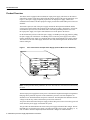
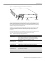
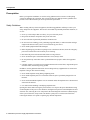
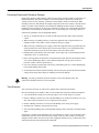
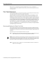
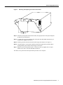
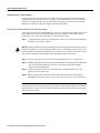
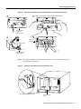
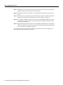
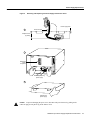
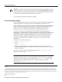
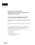
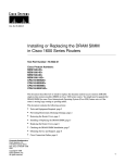
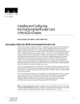
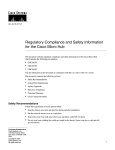
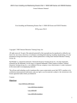
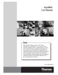
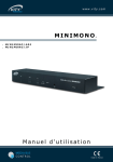
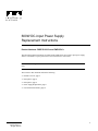
Doc. No. 78-1455-02
600W DC-Input Power Supply
Replacement Instructions
Product Numbers: PWR-7010-DC= and PWR/5-DC=
This document contains instructions for replacing the 600W, direct current (DC)–input power supply
which is a available as a spare part for the Cisco 7010 and Cisco 7505 router.
Note When referring to both the Cisco 7010 and Cisco 7505 chassis, the term the chassis will be
used.
The sections in this document include the following:
•
•
•
•
•
Copyright © 1995
Cisco Systems, Inc.
All rights reserved.
Product Overview, page 2
Prerequisites, page 4
Prerequisites, page 4
Power Supply Replacement, page 6
Cisco Information Online, page 14
1
Product Overview
Product Overview
The chassis can be equipped with one 600W, DC-input power supply, which rests on the interior
chassis floor, operates on DC input, and provides DC output voltages to the system components. (See
Figure 1.) This power supply completely replaces the AC-input power supply, which is also
available for these chassis. The DC-input power supply is used where isolated DC power sources are
desirable.
The interface processor end of the power supply contains the DC-input terminal block and the
system power on/off switch, both of which are part of the power supply. (See Figure 2.) The front,
or noninterface processor end, of the chassis has a removable panel that provides access to the
DC-input power supply. Two captive slotted fasteners secure the panel to the chassis.
On the noninterface processor end of the power supply, two handles provide grip points for pulling
the power supply out of the chassis. Two Phillips screws secure the power supply to the chassis
interior. Inside the power supply, two small fans draw cooling air through the power supply interior.
The air flows in one side of the supply and out the other side, following the same direction as the
chassis cooling air.
Cisco 7010 with the DC-Input Power Supply (Terminal Block Cover Removed)
H2535
Figure 1
DC-input
power supply
Note For the procedures in this publication, the Cisco 7010 and Cisco 7505 chassis are functionally
the same.
The DC-input power supply delivers DC power to the internal components through a wiring harness
that plugs into a polarized receptacle on the noninterface processor side of the backplane. An
aluminum cover shields the harness and power connection. The backplane then distributes the DC
voltages to the fan tray, arbiter, and interface processor bus connectors.
Two power cable leads connect the power supply to the site DC power source. The rocker-type on/off
switch turns the power supply on and starts the system.
The green DC OK LED indicates the status of the power supply and internal DC voltages. The DC
OK LED stays on when the power supply is on and receiving DC source power, providing +5, 12,
and +24 VDC to internal components, and all internal DC voltages are within tolerance.
2 600W DC-Input Power Supply Replacement Instructions
Product Overview
DC-Input Power Supply (Terminal Block Cover Removed)
H2536
Figure 2
Terminal
block
On/Off
switch
DC-input
power supply
DC OK LED
If the DC source power or any of the internal DC voltages exceeds allowable tolerances, the DC OK
LED goes off and the system environmental monitor messages indicate the line that is out of
tolerance. Because the Route Processor (RP) (which uses +5 and 12 VDC), and the fan tray (which
uses +24 VDC) are both required for operation, the system will probably shut down if any of the four
internal DC voltages reach an out-of-tolerance state.
In addition to the environmental monitoring performed by the system software, the power supply
monitors its own temperature and internal voltages. If the supply detects an overvoltage or
overtemperature condition, it shuts down to avoid damage to the power supply or other system
components.
If the power supply shuts down, wait for the supply to cool, then turn the power switch off (O), then
on (|). Table 1 lists the power specifications for the 600W, DC-input power supply.
Table 1
600W, DC-Input Power Supply Specifications
Specification
Rating
DC-input voltage
–40 volts DC (VDC) minimum in North America (–56V in the European Community)
–48 VDC nominal in North America (–60V in the European Community)
–52 VDC maximum in North America (–72V in the European Community)
20A maximum at –48 VDC and 16A maximum @ –60 VDC
DC voltages supplied and
maximum, steady-state
current ratings
+5.2 VDC @ 75 amps (A)
+12 VDC @ 15A
–12 VDC @ 3A
+24 VDC @ 5A
DC-input hold-up time
10 milliseconds (ms) of output after the DC input has been interrupted
Input power requirement
1000 watts (W)
Power output
600 W maximum
Heat dissipation
and temperature range
1024 Btu/hr (300 W)
32 to 104 F (0 to 40 C) (operating)
Weight
12 pounds (5.44 kilograms)
Wire gauge for power cable
10 AWG (American Wire Gauge) minimum
600W DC-Input Power Supply Replacement Instructions
3
Prerequisites
Prerequisites
Before you begin this installation, review the safety guidelines in this section to avoid injuring
yourself or damaging the equipment. This section also discusses ESD prevention guidelines and
provides a list of the tools that you need to perform this replacement.
Safety Guidelines
When working with any electrical equipment, the following guidelines will help to ensure your
safety and protect the equipment. This list does not include all potentially hazardous situations, so
be alert.
•
•
•
•
Never try to lift an object that is too heavy for you to lift safely alone.
•
•
Never install equipment that looks damaged.
•
•
•
Disconnect all power and external cables before moving a chassis.
•
Carefully examine your work area for possible hazards such as moist floors, ungrounded power
extension cables, and missing safety grounds.
Keep tools and chassis components away from walk areas.
Do not work alone if potentially hazardous conditions exist.
Do not wear loose clothing, jewelry (including rings and chains), or other items that could get
caught in the chassis. Fasten your tie or scarf and roll up your sleeves.
Before beginning any procedures requiring access to the chassis interior, locate the emergency
power-off switch for the room in which you are working.
Never assume that power is disconnected from a circuit; always check.
Do not perform any action that creates a potential hazard to people or makes the equipment
unsafe.
In addition, use the guidelines that follow when working with any equipment that is connected to
telephone wiring or other network cabling:
•
•
Never install telephone wiring during a lightning storm.
•
Never touch uninsulated telephone wires or terminals unless the telephone line is disconnected
at the network interface.
•
Use caution when installing or modifying telephone lines.
Never install telephone jacks in wet locations unless the jack is specifically designed for wet
locations.
Opening the chassis and removing the power harness cover exposes the power distribution wiring
on the backplane. If the power is not shut down, the high current present on the backplane becomes
a hazard. Also, removing the cover compromises the electromagnetic interference (EMI) integrity
of the system. Therefore, always make sure that the system power switch is turned off before
removing the chassis cover panel or replacing any internal components.
4 600W DC-Input Power Supply Replacement Instructions
Prerequisites
Preventing Electrostatic Discharge Damage
Electrostatic discharge (ESD) damage, which can occur when electronic boards or components are
handled improperly, can result in complete or intermittent failures. The RP, SP (or SSP), and
interface processors each comprise a printed circuit board that is fixed in a metal carrier. EMI
shielding, connectors, and a handle are integral components of the carrier. However, the fan control
board is a printed circuit board that is not intended for handling and has no frame or shielding.
Handle a processor module or fan tray by the metal frame or carrier only; avoid touching the board
(particularly avoid touching any components, traces, or the metal fingers on the edge connector).
Following are guidelines for preventing ESD damage:
•
Always use an ESD-preventive wrist strap or ankle strap and ensure that it makes good skin
contact.
•
When removing or installing a fan tray, connect the equipment end of a ground strap to an
unpainted surface of the chassis, such as a handle on the power supply.
•
When removing or installing a power supply, connect the equipment end of a ground strap to the
chassis ground screw on the interface processor end of the chassis, or to an unpainted surface
inside the noninterface processor end of the chassis, such as the chassis frame.
•
Handle printed circuit boards, such as the arbiter, by the edges only; avoid touching the board
components, traces, or connector pins.
•
Place removed printed circuit boards or components that contain boards on an antistatic surface
or in a static shielding bag. Place a removed board component-side-up; place a removed
processor module or fan tray board-side-up.
•
If you are returning a replaced part to the factory, immediately place it in a static shielding bag
to avoid ESD damage to the board.
•
Avoid contact between the board and clothing. The wrist strap only protects the board from ESD
voltages on the body; ESD voltages on clothing can still cause damage.
Warning For safety, periodically check the resistance value of the antistatic strap. The
measurement should be between 1 and 10 megohm.
Tools Required
This section lists the tools you will need to complete these replacement procedures.
Have the following tools available so that you can complete the replacement without interruption:
•
•
3/16-inch flat-blade screwdriver to loosen the captive screws on the chassis cover panel
•
•
•
Number 2 Phillips screwdriver to remove the M4 Phillips screw on the power supply
Number 1 Phillips screwdriver to remove the M3 Phillips screw on the power harness cover (you
must remove the power harness cover to replace the power supply)
Antistatic mat or antistatic foam pad for the fan tray
Your own ESD grounding strap or the disposable ESD-preventive strap that is included with all
spares
If the chassis is mounted in an equipment rack, ensure that there is at least 1 foot of clearance at the
noninterface processor end to remove the power supply or fan tray, both of which you must pull
straight out of the chassis. If a power strip or other equipment obstructs access, you must remove the
chassis from the rack before replacing the component.
600W DC-Input Power Supply Replacement Instructions
5
Power Supply Replacement
Refer to the Cisco 7010 Hardware Installation and Maintenance or Cisco 7505 Hardware
Installation and Maintenance publications for the tools you will need and descriptions of the rack
mounting hardware.
Power Supply Replacement
To access the power supply, you must remove the chassis cover panel and expose the chassis interior.
Two captive slotted screws secure the cover panel to the chassis.
The power supply rests on the floor of the chassis, under the card cage and backplane. Two M4
Phillips screws secure the power supply to the interior chassis frame. The power harness cover
shields the power harness, which carries DC voltages from the power supply to a polarized connector
on the backplane. Because the power harness cover straddles both the power supply and backplane
cover, you must remove it to access the power supply. A tab at the bottom of the power harness cover
fits into a slot in the chassis floor; a single Phillips screw secures the top of the power harness cover
to the backplane cover. To remove the power supply, you need to disconnect the DC-input power
cable, remove the power harness cover, disconnect the power harness from the backplane, and
remove the two M4 Phillips screws. The noninterface processor end of the power supply has handles
for pulling the supply out of the chassis.
Removing and Replacing the Chassis Cover Panel
The two captive slotted screws are the only fasteners on the cover panel. Five shallow tabs at the
bottom edge of the panel fit into slots at the base of the chassis opening. The tabs act as a pivot point
for pulling the top of the panel away from the chassis opening, and as guides to align the panel when
replacing it.
Follow these steps to remove and replace the chassis cover panel:
Step 1 Turn OFF (O) power to the chassis, turn OFF the source power, and disconnect the power
cable at the DC power source. You can leave the ground cable connected.
Warning Before conducting any of the following procedures, and to prevent short-circuit or shock
hazards, ensure that power is removed from the DC circuit. To ensure that all power is OFF, locate
the circuit breaker on the panel board that services the DC circuit, switch the circuit breaker to the
OFF position, and tape the switch handle of the circuit breaker in the OFF position.
Step 2 On the front of the cover panel, use a 3/16-inch, flat-blade screwdriver to loosen the two
captive screws. (See Figure 3.)
6 600W DC-Input Power Supply Replacement Instructions
Power Supply Replacement
Removing and Replacing the Chassis Cover Panel
H2920
Figure 3
Captive screws
Step 3 Pull the top of the panel out about three inches, then grasp the sides of the panel and pull it
up and away from the chassis.
Step 4 To replace the cover panel, hold the sides of the panel with both hands and tilt the top of
the panel back slightly (toward you).
Step 5 Slide the guide tabs into the slots in the bottom edge of the chassis. (See Figure 3.)
Step 6 Using the guides as a pivot point, push the top half of the panel back toward the chassis
opening until the panel is flush with the edges of the chassis.
Step 7 Hold the top front of the panel in place, if necessary, while you tighten the two captive
slotted screws with a 3/16-inch, flat-blade screwdriver.
The chassis cover panel removal and replacement procedure is now complete.
600W DC-Input Power Supply Replacement Instructions
7
Power Supply Replacement
Replacing the Power Supply
You must remove the power harness cover and disconnect the power harness from the backplane
receptacle before you can remove the power supply. A single M3 Phillips screw secures the power
harness cover to the backplane cover. To remove the power supply, you will remove the two M4
Phillips screws that secure the power supply ears to the chassis frame.
Removing the Power Harness Cover and Power Supply
Follow these steps to remove the terminal block cover, power cable leads, power harness cover, and
power supply. You will need a medium flat-blade screwdriver, number 1 and number 2 Phillips
screwdrivers, one or two 6-inch nylon cable ties, and a small wire cutter.
Step 1 To open the chassis, follow Step 1 through Step 3 in the section “Removing and Replacing
the Chassis Cover Panel” on page 6.
Warning Before conducting any of the following procedures, and to prevent short-circuit or shock
hazards, ensure that power is removed from the DC circuit. To ensure that all power is OFF, locate
the circuit breaker on the panel board that services the DC circuit, switch the circuit breaker to the
OFF position, and tape the switch handle of the circuit breaker in the OFF position.
Step 2 Loosen the two captive screws that secure the terminal block cover. (See Figure 4a.)
Step 3 Pull the terminal block cover away from the terminal block by feeding the return (RTN) and
–48V wires through the large hole in the cover. (See Figure 4b.) Do not strain the
connections at the terminal block.
Step 4 Cut the nylon cable tie that secures the cable leads to the terminal block cover. (See
Figure 4b.) Do not cut the wires.
Step 5 Remove the RTN and –48V leads from the terminal block. Note the color coding for
reinstallation. (See Figure 4d.) Leave the ground cable connected to the ground terminal.
Note Selection of the color code for the power cable leads depends on the color code of the DC
power source at your site. Typically, green or green/yellow is used for ground, black is used for RTN,
and red or white are used for –48V. No matter which color coding is used, make certain it matches
that used at the DC source.
8 600W DC-Input Power Supply Replacement Instructions
Power Supply Replacement
Figure 4
Removing and Replacing the Terminal Block Cover and Power Cable Leads
a
b Caution: Do not strain the connection at the terminal block
-48/-60V —
20/16A
-48
RTN
-48/-60V —
20/16A
-48
RTN
POWER SUPPLY
TERM. BLOCK COVER
- USE ONLY WITH
NEC CLASS 3
WIRING
- USE COPPER
CONDUCTORS
POWER SUPPLY
TERM. BLOCK COVER
- USE ONLY WITH
NEC CLASS 3
WIRING
- USE COPPER
CONDUCTORS
Terminal block
cover and
captive screws
d
c
-48/-60V —
20/16A
-48
RTN
H2537
Ground
terminal
Cable strain relief
nylon cable tie
Step 6 Use a number 1 Phillips screwdriver to remove the M3 screw that secures the harness cover
to the backplane. (See Figure 5.)
Removing and Replacing the Power Harness Cover
H2924
Figure 5
Removing power harness cover
Power harness
cover
600W DC-Input Power Supply Replacement Instructions
9
Power Supply Replacement
Step 7 Holding the cover with one hand, tilt the top of the cover back toward you, then pull it up
slightly so that the tab clears the slot in the chassis floor.
Step 8 When the tab clears the slot, pull the cover straight back OFF the harness and out of the
chassis.
Step 9 Disconnect the power harness plug from the backplane receptacle by pulling the polarized
plug out of the receptacle; do not pull on the wires. (See Figure 6a on page 11.)
Step 10 Use a number 2 Phillips screwdriver to remove the two M4 Phillips panhead screws that
secure the power supply ears (one on each side of the power supply) to the chassis frame.
(See Figure 6a on page 11.)
Step 11 Using both hands, grasp both of the power supply handles and pull the power supply about
halfway out of the bay (see Figure 6b on page 11), then grab the sides of the supply and pull
it out of the chassis. (See Figure 6c page 11.)
The power supply removal procedure is complete. Proceed to the next section to install the new
power supply and replace the power harness cover.
10 600W DC-Input Power Supply Replacement Instructions
Power Supply Replacement
Figure 6
Removing and Replacing the Power Supply and Harness Cover
Power supply ears
a.
Power harness
Phillips screws
(2 places)
b.
Backplane
power
receptacle
Removing/replacing
power supply
H2921
c.
Handling the
power supply
To prevent damaging the power wires, disconnect the power harness by pulling on the
connector plug; do not pull or tug on the harness wires.
Caution
600W DC-Input Power Supply Replacement Instructions
11
Power Supply Replacement
Replacing the Power Supply and Power Harness Cover
Follow these steps to remove the power harness cover and power supply. You will need a number 2
Phillips screwdriver.
Note The installation must comply with the 1993 National Electrical Code and other applicable
codes.
Step 1 Ensure that the power switch on the new power supply is in the OFF (O) position and that
the terminal block cover is not installed on the new power supply.
Step 2 Hold the supply as shown in Figure 6c on page 11 and slide it into the bottom of the chassis.
Use the handles to push the supply all the way into the chassis until the ears on both sides
are flush against the chassis frame.
Step 3 Use a number 2 Phillips screwdriver to replace the two M4 Phillips panhead screws to
secure the two power supply ears to the chassis frame.
Step 4 Reconnect the power harness plug to the backplane receptacle. The harness plug and
backplane receptacle are polarized with notches at the top of both guide tabs (top and
bottom) on the plug. Ensure that the plug is fully seated in the receptacle.
Step 5 To replace the power harness cover, hold the cover with one hand, with the tab on the
bottom and the open side facing away from you. Tilt the top of the panel back slightly
(toward you) and insert the tab on the bottom of the cover into the slot in the chassis floor.
(See Figure 5 on page 9.)
Step 6 While pushing the cover downward slightly to keep the bottom tab in the slot, push the top
of the cover back over the harness wires until the sides are flush against the backplane
cover. Ensure that all of the harness wires are under the cover.
Step 7 Insert the M3 screw through the top of the harness cover and use a number 1 Phillips
screwdriver to tighten it.
Step 8 Feed a sufficient length of the RTN and –48V wires (approximately three inches) away
from you and through the large hole in the terminal block cover, before attaching the leads
to the terminal block.
Step 9 Reattach and tighten the RTN and –48V leads to the terminal block. (See Figure 4d on
page 9.) Verify that you are connecting the appropriate leads to the correct terminal block
posts.
Warning Incorrectly wiring the terminal block could create a shock hazard and could damage the
power supply, power source, and chassis components. Make certain there are no loose strands that
could cause a short circuit of the power supply and power source.
Step 10 Using a nylon cable tie that you provide, fasten the RTN and –48V leads to the terminal
block cover, as shown in Figure 4c on page 9. Insert the nylon cable tie through the small
hole at the bottom of the terminal block cover and around the two leads.
Step 11 Bundle the RTN and –48V wires behind the terminal block cover so that the cover fits over
the wires and the terminal block. (See Figure 4b on page 9.) Take care not to strain the leads
on the terminal block or crimp the wires behind the cover.
12 600W DC-Input Power Supply Replacement Instructions
Power Supply Replacement
Step 12 If you removed the ground wire, reattach it now. (See Figure 4d on page 9.)
Step 13 Tighten the captive screws on the terminal block cover. (See Figure 4a on page 9.)
Warning To prevent a short-circuit or shock hazard after wiring the DC-input power supply, replace
the terminal block cover.
Step 14 To replace the chassis cover panel, follow Steps 4 through 7 in the section “Removing and
Replacing the Chassis Cover Panel” on page 6.
This completes the new power supply installation.
To restart the system, connect the three DC-input power cable leads to the DC power source, turn on
power to the chassis, and check the installation by proceeding to the following section,“Checking
the Installation.”
Checking the Installation
To complete the installation perform the following steps to verify that the new component is installed
correctly and functioning properly. These steps will also help you verify that all the active
components that you removed or disconnected as part of this replacement procedure are returned to
their previous state, when all router components (except the power supply you replaced) were
operating properly.
Step 1 Before you turn the system power switch back ON, first ensure the following:
•
The DC-input power cable is attached to the terminal block and the terminal block cover
is installed.
•
•
•
The power cable is properly connected to the DC power source.
The nylon cable tie is installed as strain relief.
The tape (that you applied earlier) is removed from the circuit breaker switch handle and
power is restored by moving the circuit breaker handle to the on position.
Step 2 Turn ON (|) the chassis power.
Step 3 About 10 seconds after you turn ON the power, verify that the normal LED on the RP or
RSP1 goes on, which indicates that the system software booted successfully. If it does go
on, proceed to the next step. If it does not go on, do the following:
•
Check the ejector levers and captive installation screws on the processor modules. If any
appear loose, use the ejector levers to reseat the processor, then tighten the captive
installation screws to secure it. Turn the power OFF and back ON again.
•
While the system starts up, observe the behavior of the LEDs on the RP or RSP1 (so
that you can report the behavior to a service representative if you need to call for
technical assistance). If the RP or RSP1 normal LED still remains off, note whether the
boot fail LED (on the RP) or CPU halt LED (on the RSP1) go on, and contact a service
representative for further instructions.
Step 4 After the system initializes, use the various show environment commands to display the
status of the power supply, and ensure that it is operating within normal specifications. (For
descriptions and examples of these commands, refer to the section “Prerequisites” on page
4.)
600W DC-Input Power Supply Replacement Instructions
13
Cisco Information Online
For the Cisco 7010, the system can identify which type of power supplies are in your
chassis: DC-input or AC-input. As a general precaution, use the show environment all command
and note the type of power supply indicated in each of your chassis (indicated as either “600W DC”
or “600W AC”). Record and save this information in a secure place.
Timesaver
The power supply replacement procedures are complete.
Cisco Information Online
Cisco Information Online (CIO) is Cisco Systems’ primary, real-time support channel. Maintenance
customers and partners can self-register on CIO to obtain additional content and services.
Available 24 hours a day, 7 days a week, CIO provides a wealth of standard and value-added services
to Cisco’s customers and business partners. CIO services include product information, software
updates, release notes, technical tips, the Bug Navigator, configuration notes, brochures,
descriptions of service offerings, and download access to public and authorized files.
CIO serves a wide variety of users through two interfaces that are updated and enhanced
simultaneously—a character-based version and a multimedia version that resides on the World Wide
Web (WWW). The character-based CIO (called “CIO Classic”) supports Zmodem, Kermit,
Xmodem, FTP, Internet e-mail, and fax download options, and is excellent for quick access to
information over lower bandwidths. The WWW version of CIO provides richly formatted
documents with photographs, figures, graphics, and video, as well as hyperlinks to related
information.
You can access CIO in the following ways:
•
•
•
WWW:
Telnet:
http://www.cisco.com
cio.cisco.com
Modem: From North America, 408 526-8070; from Europe, 33 1 64 46 40 82. Use the
following terminal settings: VT100 emulation; data bits: 8; parity: none; stop bits: 1; and baud
rates up to 14.4 kbps.
For a copy of CIO’s Frequently Asked Questions (FAQ), contact
additional information, contact [email protected].
[email protected].
For
Note If you are a network administrator and need personal technical assistance with a Cisco
product that is under warranty or covered by a maintenance contract, contact Cisco’s Technical
Assistance Center (TAC) at 800 553-2447, 408 526-7209, or [email protected]. To obtain general
information about Cisco Systems, Cisco products, or upgrades, contact 800 553-6387,
408 526-7208, or [email protected].
This document is to be used in conjunction with the Cisco 7010 Hardware Installation and Maintenance or Cisco 7505 Hardware Installation and Maintenance publications.
(1455dc05.fm)
Access Without Compromise, Catalyst, CD-PAC, CiscoFusion, Cisco Internetwork Operating System, Cisco IOS, CiscoView, CiscoWorks, HyperSwitch, LAN2LAN, LAN2LAN
Enterprise, LAN2LAN Remote Office, LAN2PC, LightStream, Newport Systems Solutions, PC2LAN/X.25, Point and Click Internetworking, SMARTnet, SynchroniCD, The Packet,
UniverCD, WNIC, Workgroup Director, Workgroup Stack, and XCI are trademarks; Access by Cisco and Bringing the power of internetworking to everyone are service marks; and Cisco,
Cisco Systems, the Cisco logo, EtherSwitch, and Kalpana are registered trademarks of Cisco Systems, Inc. All other trademarks, service marks, registered trademarks, or registered service
marks mentioned in this document are the property of their respective owners.
Copyright © 1995, Cisco Systems, Inc.
All rights reserved. Printed in USA
954R
14 600W DC-Input Power Supply Replacement Instructions