1
Operating The S gate 4
Whether you are an experienced audio engineer, just starting out, or you just want to experiment, follow the steps
below to get going. Further sections in this manual will cover basic dynamics and the associated parameters, system set-ups and applications for using dynamics processing in recording and live sound applications.
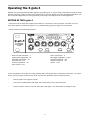
SETTING UP THE S gate 4
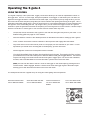
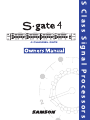
• Connect one set of inputs and outputs to the Channel 1 connectors on the rear panel. If possible, use your
mixer insert points to connect the S gate 4. For a detailed wiring, guide see page 16 in this manual.
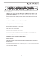
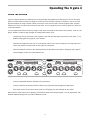
• Set the controls to the following positions:
CH 1
GAIN REDUCTION dB
30 27 24 18 12
HIGH
ATTACK
TRIGGER
+4 20
4 CHANNEL
EXPANDER
GATE
.1
RANGE
Hz
LOW
.3
mSec
300
.07 Sec
4
.02
Sec
5
0
+4 20
-50
30
KEY LISTEN
HIGH FILTER CONTROL - .1
LOW FILTER CONTROL - 30
TRIGGER CONTROL - -60
KEY SWITCH - OUT
ATTACK CONTROL - 20
KEY LISTEN - OUT
KHz 10
dB 100
3K
KEY
DUCKER
IN/OUT
Hz
LOW
dBu +20
.3
mSec
300
3K
HOLD CONTROL - .5
RELEASE CONTROL - .5 SEC
DUCKER SWITCH - OUT
RANGE CONTROL - 80
IN/OUT - OUT
In this configuration, the S gate 4 is simply passing audio at unity gain with no dynamics processing. It is a good
idea to check your gain structure at this point. Use the Gain Reduction meter to match the level.
•
Send a signal to the S gate 4ʼs inputs.
•
Look at the GAIN REDUCTION meter and confirm that no LEDʼs are illuminated.
•
Press the IN/OUT switch on and off and listen to the signal. You should hear no change in level.
6
ATTACK
TRIGGER
IN/OUT
40
.1
dBu +20
3
HIGH
1
1
CH 2
1
KHz 10
-50
30
LINK
2
RELEASE
HOLD
.25
6
KEY
KEY L