1
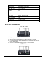
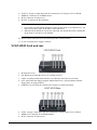
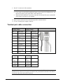
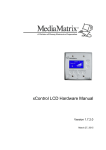
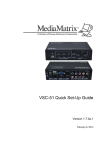
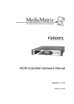
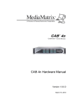
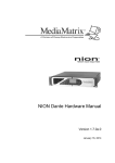
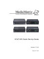
VCAT-HD Quick Set-Up Guide Version 1.7.2.0 March 27, 2015 Copyright notice The information contained in this manual is subject to change without notice. Peavey Electronics is not liable for improper installation or configuration. The information contained herein is intended only as an aid to qualified personnel in the design, installation and maintenance of engineered audio systems. The installing contractor or end user is ultimately responsible for the successful implementation of these systems. All creative content in this manual, including the layout, art design, content, photography, drawings, specifications and all other intellectual property is Copyright © 2015 Peavey Electronics Corporation. All Rights Reserved. Features & specifications subject to change without notice. All other registered trademarks or trademarks are the property of their respective owners. The ratc-server component is based in part on the work of the libwebsockets project: http://libwebsockets.org. Prepared by Peavey Digital Research, 6 Elm Place, Eynsham, Oxford, OX29 4BD, UK. Email:[email protected] (mailto:[email protected]). Scope This guide describes how to physically install a VCAT-HD-T or VCAT-HD-R HDBaseT Extender and configure it with basic settings. ii Version 1.7.2.0 March 27, 2015 1 - Important safety instructions Warning: When using electrical products, basic cautions should always be followed, including the following: 1. 2. 3. 4. 5. 6. 7. 8. 9. 10. 11. 12. 13. 14. 15. 16. 17. 18. March 27, 2015 Read these instructions. Keep these instructions. Heed all warnings. Follow all instructions. Do not use this apparatus near water. Clean only with a dry cloth. Do not block any of the ventilation openings. Install in accordance with manufacturer’s instructions. Do not install near any heat sources such as radiators, heat registers, stoves or other apparatus (including amplifiers) that produce heat. Do not defeat the safety purpose of the polarized or grounding-type plug. A polarized plug has two blades with one wider than the other. A grounding type plug has two blades and a third grounding plug. The wide blade or third prong is provided for your safety. If the provided plug does not fit into your outlet, consult an electrician for replacement of the obsolete outlet. Protect the power cord from being walked on or pinched, particularly at plugs, convenience receptacles, and the point they exit from the apparatus. Only use attachments/accessories provided by the manufacturer. Use only with a cart, stand, tripod, bracket, or table specified by the manufacturer, or sold with the apparatus. When a cart is used, use caution when moving the cart/apparatus combination to avoid injury from tip-over. Unplug this apparatus during lightning storms or when unused for long periods of time. Refer all servicing to qualified service personnel. Servicing is required when the apparatus has been damaged in any way, such as power-supply cord or plug is damaged, liquid has been spilled or objects have fallen into the apparatus, the apparatus has been exposed to rain or moisture, does not operate normally, or has been dropped. Never break off the ground pin. Write for our free booklet Shock Hazard and Grounding. Connect only to a power supply of the type marked on the unit adjacent to the power supply cord. If this product is to be mounted in an equipment rack, rear support should be provided. Control panel devices, including the xControl range, D series and nTouch 60, are designed for mounting in NEMA metal enclosures. Grounding to the front plate is required. Note for UK only: If the colors of the wires in the mains lead of this unit do not correspond with the terminals in your plug‚ proceed as follows: Version 1.7.2.0 1 a) The wire that is colored green and yellow must be connected to the terminal that is marked by the letter E‚ the earth symbol‚ b) colored green or colored green and yellow. c) The wire that is colored blue must be connected to the terminal that is marked with the letter N or the color black. d) The wire that is colored brown must be connected to the terminal that is marked with the letter L or the color red. 19. This electrical apparatus should not be exposed to dripping or splashing and care should be taken not to place objects containing liquids, such as vases, upon the apparatus. 20. The on/off switch in this unit does not break both sides of the primary mains. Hazardous energy can be present inside the chassis when the on/off switch is in the off position. The mains plug or appliance coupler is used as the disconnect device, the disconnect device shall remain readily operable. 21. Exposure to extremely high noise levels may cause a permanent hearing loss. Individuals vary considerably in susceptibility to noise-induced hearing loss, but nearly everyone will lose some hearing if exposed to sufficiently intense noise for a sufficient time. The U.S. Government’s Occupational Safety and Health Administration (OSHA) has specified the following permissible noise level exposures: Duration Per Day in Hours Sound Level dBA, Slow Response 8 90 6 92 4 95 3 97 2 100 1½ 102 1 105 ½ 110 ¼ or less 115 According to OSHA, any exposure in excess of the above permissible limits could result in some hearing loss. Ear plugs or protectors to the ear canals or over the ears must be worn when operating this amplification system in order to prevent a permanent hearing loss, if exposure is in excess of the limits as set forth above. To ensure against potentially dangerous exposure to high sound pressure levels, it is recommended that all persons exposed to equipment capable of producing high sound pressure levels such as this amplification system be protected by hearing protectors while this unit is in operation. SAVE THESE INSTRUCTIONS! 2 Version 1.7.2.0 March 27, 2015 2 - Introduction What is VCAT-HD? VCAT-HD is an HDBaseT extender comprising transmitter (VCAT-HD-T) and receiver (VCAT-HD-R). VCAT-HD delivers HDMI video signals and IR and RS-232 control signals over a single STP cable. The maximum transmission distance is 70 meters (230 ft) with CAT5e/CAT6 cable. Features Support for full HD. Delivers high resolution image (1080p@60Hz@48 b/pixels/3D/4Kx2K). Max transmission distance is 70 meters over single CAT5e/CAT6 cable. High Bandwidth: 10.2Gb/s. HDTV compatible. HDMI 1.4 and HDCP compliant. Connects an HDMI EDID and HPD source, using a CAT5e twisted pair. Bi-directional RS232 control. Bi-directional IR control. Uses HDBaseT technology. LED indicators show system status. Wall/table-mountable aluminum enclosure, PT case design. External power supply (100Volt~240Volt AC, 50/60Hz). What's in the box? VCAT-HD products are packaged in a single container. This container includes the following items: 1 x VCAT-HD-T 1 x VCAT-HD-R 4 x Mounting ears 8 x Screws 2 x Power adapter (DC 5V) 2 x Captive screw connectors 1 x User manual If any of these items are missing, please contact your Authorized Peavey MediaMatrix contractor/dealer. March 27, 2015 Version 1.7.2.0 3 3 - Installation and configuration Installing the VCAT-HD devices 1. Connect one end of an HDMI cable to an HDMI video source (such as a Blu-ray DVD player), then connect the other end to the HDMI IN port of the VCAT-HD-T. 2. Connect one end of a CAT-5e or CAT-6 cable to the TP OUT port of the VCAT-HD-T, then connect the other end to the TP IN port of the VCAT-HD-R. 3. Connect one end of an HDMI cable to a video monitor, then connect the other end to the HDMI OUT port of the VCAT-HD-R. 4. Connect the DC 5V power cables to both the VCAT-HD-T and VCAT-HD-R. 5. If you want to use the IR IN and IR OUT ports for infrared communications, rather than the internal IR sensors (labeled IR on the front of each device), connect the external devices to the IR IN and IR OUT ports on the VCAT-HD-T and VCAT-HD-R. Notes: If you want to use the IR IN and IR OUT ports on one of the VCAT-HD devices, you must also use these ports on the other VCAT-HD device. When the IR IN and IR OUT ports are connected, the internal IR sensors (labeled IR on the front of each device) are disabled. 4 Version 1.7.2.0 March 27, 2015 4 - Reference information Specification VCAT-HD-T VCAT-HD-R Input Signal 1 HDMI, 1 IR, 1 RS-232 1 IR, 1 RJ-45, 1 RS-232 Input Connector HDMI, 1/8” 3.5mm IR in 1/8” 3.5mm IR in, RJ-45 Video Signal HDMI 1.4 Audio Embedded HDMI audio Input Output Output 1 RJ-45, 1 IR, 1 RS-232 1 HDMI, 1 IR, 1 RS-232 Output Connector 1 RJ-45, 1/8” 3.5mm IR out 1 HDMI, 1/8” 3.5mm IR out Video signal HDMI 1.4 Transmission Mode HD Base T General March 27, 2015 Resolution Range 800x600 ~ 1920x1200 Transmission Distance Max distance 70M Gain 0dB ~ 10dB@100MHz SNR >70dB@ 100MHz-100M Differential Phasic Error ±10° @ 135MHz_100M Bandwidth 10.2Gbps Return Lost <-30dB@5KHz THD <0.005%@1KHz Version 1.7.2.0 5 HDMI Standard Supports HDMI 1.4 and HDCP Min.~Max. Level <0.3V ~ 1.45Vp-p Impedance 75Ω Temperature -20 ~ +60°C Humidity 10% ~ 90% Power Supply 100VAC ~ 240VAC, 50/60Hz Power Consumption 6.5W Case Dimension L134xW77xH30mm Net Weight 0.8Kg VCAT-HD-T front and rear 1. 2. 3. 4. IR internal receiver. ON: Blinks green when the transmitter is working correctly. LINK: Twisted pair link status indicator. On when the connection is successful. IN: Solid when the display supports HDCP and the key is passed; Blinks when the display does not support HDCP. 5. POWER: Lit (red) when the external power supply is connected properly. 6 Version 1.7.2.0 March 27, 2015 6. 7. 8. 9. TP OUT: Accepts a single data cable for connection to TP IN port of VCAT-HD-R. HDMI IN: Connector for an HDMI source. IR IN: Connector for IR receiver. IR OUT: Connector for IR transmitter. Notes: If you want to use the IR IN and IR OUT ports on one of the VCAT-HD devices, you must also use these ports on the other VCAT-HD device. When the IR IN and IR OUT ports are connected, the internal IR sensors (labeled IR on the front of each device) are disabled. 10. RS232: Serial connector for bi-directional pass-thru communications. 11. 5V DC: External power supply connector. VCAT-HD-R front and rear 1. 2. 3. 4. IR internal receiver. ON: Blinks green when the receiver is working correctly. LINK: Twisted pair link status indicator. On when the connection is successful. OUT: Solid when the display supports HDCP and the key is passed; Blinks when the display does not support HDCP. 5. POWER: Lit (red) when the external power supply is connected properly. 6. TP IN: Accepts a single data cable for connection to TP OUT port of VCAT-HD-T. 7. HDMI OUT Connector for an HDMI monitor. 8. IR IN: Connector for IR receiver. March 27, 2015 Version 1.7.2.0 7 9. IR OUT: Connector for IR transmitter. Notes: If you want to use the IR IN and IR OUT ports on one of the VCAT-HD devices, you must also use these ports on the other VCAT-HD device. When the IR IN and IR OUT ports are connected, the internal IR sensors (labeled IR on the front of each device) are disabled. 10. RS232: Serial connector for bi-directional pass-thru communications. 11. 5V DC: External power supply connector. Twisted pair cable connection TIA/EIA T568A TIA/EIA T568B Pin Cable color Pin Cable color 1 green white 1 orange white 2 green 2 orange 3 orange white 3 green white 4 blue 4 blue 5 blue white 5 blue white 6 orange 6 green 7 brown white 7 brown white 8 brown 8 brown Ist ground 4-5 1st ground 4-5 2nd ground 2nd ground 3-6 1-2 3rd group 1-2 3rd group 3-6 4th group 4th group 7-8 7-8 Note: For better transmission, shielded data cable is recommended. This includes using shielded, metal connectors. For proper termination, the ground/shield of the data cable must be connected to the metal shell of the connector. 8 Version 1.7.2.0 March 27, 2015 Warranty statement MediaMatrix® PEAVEY ELECTRONICS CORPORATION DOMESTIC (USA) LIMITED WARRANTY Effective Date: May 1, 2005 What This Warranty Covers This Warranty covers defects in material and workmanship in Peavey MediaMatrix products purchased and serviced in the United States of America (USA). passive filter networks.) and all Accessory Products How To Get Warranty Service End Users: Take the defective product and your dated sales receipt or other proof of purchase to your Authorized MediaMatrix Systems Integrator or Authorized Peavey Service Center. System Integrators: Ship the defective product, prepaid, to Peavey Electronics Corporation, International Service Center, 412 Highway 11 & 80 East, Meridian, MS 39301, 601-483-5365. Include a detailed description of the problem, the name and location of the jobsite and a copy of your invoice as evidence of warranty coverage. Please include a complete return shipping address. What This Warranty Does Not Cover The Warranty does not cover: (1) damage caused by accident, misuse, abuse, improper installation or operation, rental, product modification or neglect; (2) damage occurring during shipment; (3) damage caused by repair or service performed by persons not authorized by Peavey; (4) products on which the serial number has been altered, defaced or removed; (5) products not purchased from an Authorized MediaMatrix Integrator. This warranty does not cover associated costs incurred from servicing equipment, including, but not limited to, travel, jobsite-related costs, fabrication, freight, loaner equipment, installation, cabling or harnessing, mounting materials or other variable costs. Who This Warranty Protects In applications where the product is sold over the counter, this Warranty protects the original retail purchaser. In applications where the product is part of an integrated system, and such system is warrantied by the integrator as a complete assembly, this Warranty protects only the system integrator. What Peavey Will Do We will repair or replace (at Peavey's discretion) products covered by warranty at no charge for labor or materials. If the product or component must be shipped to Peavey for warranty service, the consumer must pay initial shipping costs. If the repairs are covered by warranty, Peavey will pay the return shipping costs. How Long This Warranty Lasts The Warranty begins on the date of purchase by the original retail purchaser or on the date received by the system integrator. (See Who This Warranty Protects, above). The duration of the Warranty varies by product as summarized below. 5 Years MediaMatrix® DPU cards, NION™ Processing Nodes, CABs, I/O cards, Cinema Processors, Power Amplifiers, Pre-Amplifiers, Mixers, Electronic Filter Sets and Dynamics Processors. 1 Year MM Series Cardframes, MF Series Cardframes, ControlMatrix™ Host Processors, Servers and Controllers, nControl, nTouch 180, nTouch 60, xControl LCDs, nWall, VCAT, VCAT-HD, VGA-2, VSC, D4S, D1V, Remote Control Panels, Plates, Paging Stations, Ambient Sense Devices and other devices installed in user-accessible locations. 90 Days Loudspeaker Components (including speakers, baskets, drivers, diaphragm replacement kits and March 27, 2015 Version 1.7.2.0 Limitation of Implied Warranties ANY IMPLIED WARRANTIES, INCLUDING WARRANTIES OF MERCHANTABILITY AND FITNESS FOR A PARTICULAR PURPOSE, ARE LIMITED IN DURATION TO THE LENGTH OF THIS WARRANTY. Some states do not allow limitations on how long an implied warranty lasts, so the above limitation may not apply to you. Exclusions of Damages PEAVEY'S LIABILITY FOR ANY DEFECTIVE PRODUCT IS LIMITED TO THE REPAIR OR REPLACEMENT OF THE PRODUCT, AT PEAVEY'S OPTION. IF WE ELECT TO REPLACE THE PRODUCT, THE REPLACEMENT MAY BE A RECONDITIONED UNIT. PEAVEY SHALL NOT BE LIABLE FOR DAMAGES BASED ON INCONVENIENCE, LOSS OF USE, LOST PROFITS, LOST SAVINGS, DAMAGE TO ANY OTHER EQUIPMENT OR OTHER ITEMS AT THE SITE OF USE, OR ANY OTHER DAMAGES WHETHER INCIDENTAL, CONSEQUENTIAL OR OTHERWISE, EVEN IF PEAVEY HAS BEEN ADVISED OF THE POSSIBILITY OF SUCH DAMAGES. Some states do not allow the exclusion or limitation of incidental or consequential damages, so the above limitation or exclusion may not apply to you. This Warranty gives you specific legal rights, and you may also have other rights which vary from state to state. If you have any questions about this warranty or service received, or if you need assistance in locating an Authorized Service Center, please contact the Peavey International Service Center at (601) 483-5365. Features and specifications subject to change without notice. 9 MediaMatrix® A Division of Peavey Electronics Corp. 5022 Hartley Peavey Drive, Meridian Mississippi, 39305, USA Phone: 866.662.8750 http://www.peaveycommercialaudio.com/products.cfm/mm/ Features & Specifications subject to change without notice Copyright © 2015, All Rights Reserved 80307513