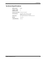
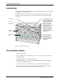
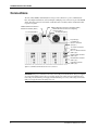
1
CC9600 Chassis User Guide CC9600 Chassis User Guide P/N 82064902, Revision C Copyright © 1997 by Multi-Tech Systems, Inc. All rights reserved. This publication may not be reproduced, in whole or in part, without prior expressed written permission from Multi-Tech Systems, Inc. Multi-Tech Systems, Inc. makes no representation or warranties with respect to the contents hereof and specifically disclaims any implied warranties of merchantability or fitness for any particular purpose. Furthermore, Multi-Tech Systems, Inc. reserves the right to revise this publication and to make changes from time to time in the content hereof without obligation of Multi-Tech Systems, Inc., to notify any person or organization of such revisions or changes. Revision Date A 3/31/97 Manual released. Description B 5/27/97 Manual updated. C 11/17/97 Manual revised to include new FCC information and removal of service information Multi-Tech, CommPlete, RASExpress, MultiExpress, MultiExpress Fax MultiModem, MultiModemZDX, MultiModemManager, and the Multi-Tech logo are trademarks of Multi-Tech Systems, Inc. Other trademarks and trade names mentioned in this publication belong to their respective owners. Multi-Tech Systems, Inc. 2205 Woodale Drive Mounds View, Minnesota 55112 (612) 785-3500 or (800) 328-9717 U.S. Fax (612) 785-9874 Technical Support (800) 972-2439 BBS (612) 785-3702 or (800) 392-2432 Fax Back (612) 717-5888 Internet Address: http://www.multitech.com Federal Communications Commission Statement This equipment has been tested and found to comply with the limits for a Class A digital device, pursuant to Part 15 of the FCC Rules. These limits are designed to provide reasonable protection against harmful interference when the equipment is operated in a commercial environment. This equipment generates, uses, and can radiate radio frequency energy, and if not installed and used in accordance with the instruction manual, may cause harmful interference to radio communications. Operation of this equipment in a residential area is likely to cause harmful interference, in which case the user will be required to correct the interference at his own expense. Warning: Changes or modifications to this unit not expressly approved by the party responsible for compliance could void the user’s authority to operate the equipment. Exhibit J (Consumer Instructions) This equipment complies part 68 of the Federal Communications Commission Rules. On the outside surface of this equipment is a label that contains, among other information, the FCC registration number. This information must be provided to the telephone company. As indicated below, the suitable jack (Universal Service Order Code connecting arrangement) for this equipment is shown. If applicable, the facility interface codes (FIC) and service order codes (SOC) are shown. A FCC-compliant telephone cord and modular plug is provided with this equipment. This equipment is designed to be connected to the telephone network or premises wiring using a compatible modular jack which is Part 68 compliant. See installation instructions for details. If this equipment causes harm to the telephone network, the telephone company will notify you in advance that temporary discontinuance of service may be required. But if advance notice is not practical, the telephone company will notify the customer as soon as possible. Also, you will be advised of your right to file a complaint with the FCC if you believe it is necessary. The telephone company may make changes in its facilities, equipment, operations, or procedures that could affect the operation of the equipment. If this happens, the telephone company will provide advance notice in order for you to make necessary modifications in order to maintain uninterrupted service. If trouble is experienced with this equipment (the model of which is indicated below) please contact MultiTech Systems, Inc. at the address shown below for details of how to have repairs made. If the equipment is causing harm to the network, the telephone company may request you to remove the equipment from the network until the problem is resolved. CommPlete Communications Server iii No repairs are to be made by you. Repairs are to be made only by MultiTech Systems or its licensees. Unauthorized repairs void registration and warranty. Manufacturer: MultiTech Systems, Inc. Trade Name: CommPlete Model Number: CC9600 FCC Registration Number: AU7USA-31090-DE-E Facility Interface Code: Service Order Code: 04DU9-ISN, 04DU9-BN 6.0N Modular Jack (USOC): RJ48C Service Center in USA: MultiTech Systems, Inc. 2205 Woodale Drive Mounds View, MN 55112 (612) 785-3500 Fax (612) 785-9874 FCC Fax Warning The Telephone Consumer Protection Act of 1991 makes it unlawful for any person to use a computer or other electronic device to send any message via a telephone fax machine unless such message clearly contains in a margin at the top or bottom of each page or the first page of the transmission, the date and time it is sent and an identification of the business or other entity, or other individual sending the message and the telephone number of the sending machine or such business, other entity, or individual. See your fax software manual for setup details. iv CommPlete Communications Server Canadian Limitations Notice Notice: The ringer equivalence number (REN) assigned to each terminal device provides an indication of the maximum number of terminals allowed to be connected to a telephone interface. The termination of a interface may consist of any combination of devices subject only to the requirement that the sum of the ringer equivalence numbers of all the devices does not exceed 5. Notice: The Industry Canada label identifies certificated equipment. This certification means that the equipment meets certain telecommunications network protective, operational and safety requirements. The Industry Canada does not guarantee the equipment will operate to the user’s satisfaction. Before installing this equipment, users should ensure that it is permissible to be connected to the facilities of the local telecommunications company. The equipment must also be installed using an acceptable method of connection. The customer should be aware that compliance with the above conditions may not prevent degradation of service in some situations. Repairs to certified equipment should be made by an authorized Canadian maintenance facility designated by the supplier. Any repairs or alterations made by the user to this equipment, or equipment malfunctions, may give the telecommunications company cause to request the user to disconnect the equipment. Users should ensure for their own protection that the electrical ground connections of the power utility, telephone lines and internal metallic water pipe system, if present, are connected together. This precaution may be particularly important in rural areas. Caution: Users should not attempt to make such connections themselves, but should contact the appropriate electric inspection authority, or electrician, as appropriate. This digital apparatus does not exceed the Class B limits for radio noise emissions from digital apparatus set out in the Radio Interference Regulation of the Canadian Department of Communications. Le présent appareil numérique n’émet pas de bruits radioélectriques dépassant les limites applicables aux appareils numériques de la classe B prescrites dans le Règlement sur le brouillage radioélectrique édicté par le ministère des Communications du Canada. Ringer Equivalence Number Notice: The ringer equivalence number (REN) asigned to each terminal device provides an indication of the maximum number of terminals allowed to be connected to a telephone interface. The termination on an interface may consist of any combination of devices subject only to the requirement that the sum of the ringer equivalence numbers of all the devices does not exceed 5. Cooling Requirements The ambient operating temperature of the CC9600 chassis is 0° C to 40° C. Important Safety Requirements • No manual adjustments to the equipment are necessary for connection to mains power within rated voltage and frequency. CommPlete Communications Server v • The power supply cords are intended to serve as the disconnect devices. The outlet sockets must be installed near the equipment and be easily accessible. • To reduce the risk of shock, all openings should be covered during normal operation of the equipment. • Both power cords must be removed to remove all power from the chassis. The power supplies are connected in parallel, so that both power supplies supply power to all power busses in the chassis. To remove all power from the left power supply, disconnect the left power cord; to remove all power from the right power supply, disconnect the right power cord. Consignes de Sécurité • Aucun réglage manuel de l’équipement n’est nécessaire pour des connexions à l’alimentation principale sous une tension et une fréquence nominales. • Les cordons d’alimentation ont été conçus pour servir de dispositif de déconnexion. Les prises d’alimentation doyent être installées près de l’équipement et doyent être faciles d’accès. • Afin de réduire les risques de choc, toutes les ouvertures doivent être couvertes pendant le fonctionnement normal de l’équipement. Advertencias de Seguridad • No son necesarios ajustes manuales del equipo para la conexión a la corriente de la red dentro del voltaje y frecuencia establecidas. • El conector de alimentación de energía sirve como dispositivo de desconexión. La toma de corriente se debe instalar cerca del equipo y tener un acceso sencillo. • Para reducir el riesgo de sacudida eléctrica, todas las aberturas deben estar cubiertas durante el manejo normal del equipo. Sicherheitshinweise • Bei Anschluß am Versorgungsnetz innerhalb der Nennleistung und -frequenz ist es nicht erforderlich, dieses Gerät manuell nachzustellen. • Die Netzschnur dient als Trennvorrichtung. Die Steckdose muß in der Nähe des Geräts installiert werden, um leicht zugänglich zu sein. • Um Elektroschockgefahr zu vermindern, müssen beim normalen Betrieb des Geräts alle Öffnungen abgedeckt sein. vi CommPlete Communications Server Vigtige Sikkerhedskrav • Det er ikke nødvendigt at foretage manuelle justeringer af udstyret, for at tilslutte udstyret til elektrisitetsuettet indenfor de navute spændingsfrekvensgreuser. • Strømforsyningsledningen er beregnet til at fungere som afbryder. Stikkontakten skal installeres nær ved udstyret og skal være let tilgængelig. • Nedsæt risikoen for stød, ved at tildække alle udstyrets åbninger under normal drift. Power Requirements AC 100–240 V, 50/60 Hz, 8 A Alimentation Requise AC 100–240V, 50/60 Hz, 8 A Requisitos de potencia AC 100–240V, 50/60 Hz, 8 A Stromaufnahme AC 100–240V, 50/60 Hz, 8 A Strømforsyningskrav AC 100–240V, 50/60 Hz, 8 A CommPlete Communications Server vii viii CommPlete Communications Server Table of Contents 1 Introduction Introduction ...................................................................................................................................................... 2 Key Features ...................................................................................................................................................... 2 Manual Organization......................................................................................................................................... 2 Technical Specifications.................................................................................................................................... 3 2 Installation Introduction ...................................................................................................................................................... 6 Pre-Installation Notes ....................................................................................................................................... 6 Installation......................................................................................................................................................... 7 Safety Warnings................................................................................................................................................. 7 Connections ....................................................................................................................................................... 8 Appendix Appendix A Installing 3rd Party Software .....................................................................................................10 Installing Citrix WinFrame Software on the CommPlete ...................................................................10 Installing Microsoft Windows NT Software on the CommPlete ........................................................12 Installing SCO UNIX Software on the CommPlete .................................................................................13 Installing USL/Novell UNIXWare Software on the CommPlete.........................................................14 Installing BSD UNIX Software on the CommPlete..............................................................................15 CommPlete Communications Server ix x CommPlete Communications Server 1 Introduction CommPlete Communications Server 1 CC9600 Chassis User Guide Introduction The CC9600 chassis is the housing for the CommPlete Communications Server. It can contain one chassis controller module, two power supply modules (one is required, and two are recommended), four independent RASCard servers, and 96 modems (12 modem cards, with eight modems per card) or four PRI cards. The standard CC9600 chassis comes with two PS9600 300-watt, hot-swappable, redundant power supplies and an MR9600 system controller with an integrated Ethernet concentrator. Key Features • Four independent segments for any combination of T1-Starter or PRI-Starter segment kits. • Data bus eliminates serial cables. • Ethernet bus reduces network cables to one. • T1 bus works with T1 card to eliminate the need for a channel bank. • Control bus delivers management, reporting, and control information to the controller. • Side-venting cooling fans and a heat sensor with built-in reporting guard against overheating. Manual Organization Chapter 1 Introduction This chapter describes the CC9600, gives its technical specifications, and provides a guide to the organization of the manual. Chapter 2 Installation This chapter contains installation precautions and shows the location of all connectors on the rear of the CC9600. 2 CommPlete Communications Server 1 Introduction Technical Specifications Model Number CC9600 Number of Slots 16 Number of Fans 6 External Connectors Two AC power receptacles Environmental Temperature range: 0°–40° C (32°–104° F) Humidity range: 0–95% (noncondensing) Dimensions 31.1 × 48.3 × 36.8 cm (12.25 × 19 × 14.5 in.) H × W × D Weight 11 kg (25 lb.) Limited Warranty Two years CommPlete Communications Server 3 CC9600 Chassis User Guide 4 CommPlete Communications Server 2 Installation CommPlete Communications Server 5 CC9600 Chassis User Guide Introduction This chapter contains only general information about installing the CC9600 chassis. The equipment should be installed only by a qualified service person. The CC9600 is designed to be installed in a standard 19-inch-wide rack cabinet. Figure 1 shows a fully loaded chassis with one controller card, two power supplies, and a full complement of RASCards and modem cards. Power Supply The chassis can work with one or two PS9600 power supplies. The second power supply is redundant. If any of the outputs on either supply is low or fails, the other supply takes over with no switchover period, producing all the power required to run the system. (Both power supplies must be turned on; when both supplies are operating, they share the load.) Controller Power Supply I 0 I 0 RASCard server (4×) Modem cards (12×) I 0 I 0 I 0 I 0 The controller module contains a processor and memory for intelligent operation of the rack, plus an integrated Ethernet concentrator. Figure 1. A fully-loaded CC9600 chassis. Pre-Installation Notes • Unpack hardware carefully. • Perform a visual inspection of the hardware. If you are concerned about the condition of the chassis, call Technical Support. • All installation must be done by a qualified service person. • Consult the manuals for your other components (PS9600, MR9600, MTRAS96, and MTxxxxHD8) before they are installed into the CC9600. • To reduce emissions, be sure to use blanking plates to cover empty slots in the CC9600 chassis. • Only connect like circuits. In other words, connect SELV (Secondary Extra Low Voltage) circuits to SELV circuits and TN (Telecommunications Network) circuits to TN circuits. 6 CommPlete Communications Server Installation WARNING: Interconnection directly, or by way of other apparatus, of ports marked “SAFETY WARNING see instructions for use” with ports marked or not so marked may produce hazardous conditions on the network. Advice should be obtained from a competent engineer before such a connection is made. Installation • If the chassis is installed in a closed or multi-rack assembly, the operating temperature of the rack environment may be greater than the ambient temperature. Be sure to install the chassis in an environment that is compatible with the maximum rated ambient temperature. See technical specifications. • Install equipment in the rack so that forced air cooled in the equipment does not compromise safe operation. • When mounting the equipment in the rack make sure mechanical loading is even to avoid a hazardous condition, such as loading heavy equipment in the rack unevenly. • When connecting the equipment to the supply circuit, be sure to check equipment nameplate ratings to avoid overloading ciruits which may cause damage to over-current protection devices and supply wiring. • Be sure to maintain reliable earthing for rack-mounted equipment. Pay particular attention to supply connections other than direct connections to the branch circuit, such as the power strips. Safety Warnings • Never install telephone wiring during a lightning storm. • Never install telephone jacks in wet locations unless the jacks are specifically designed for wet locations. • Never touch uninsulated telephone wires or terminals unless the telephone line has been disconnected at the network interface. • Use caution when installing or modifying telephone lines. • Avoid using a telephone (other than a cordless type) during an electrical storm. There may be a remote risk of electrical shock from lightning. • Do not use the telephone to report a gas leak in the vicinity of the leak. CommPlete Communications Server 7 CC9600 Chassis User Guide Connections The rear of the CommPlete Communications Server provides connections to power, communications lines, and configuration hardware, as shown in Figure 2. Only the power connectors are part of the CC9600 chassis. The other connectors are mounted on removable cards or modules, and are documented in their respective user guides. 10BaseT Ethernet connector to external concentrator (SELV) 0 V test point (SELV) 10Base-T Ethernet connector to server NIC (SELV) DB-9P RS-232C connector for configuring controller (SELV) 5 V test point (SELV) AC power (2×) 5 V adjust (2×) RJ-48 T1 connector (TNV) (4×) T1 monitor connectors (TNV) (4×) RJ-11 T1 alarm connector (SELV) (4×) DB-9P COM1 connector (SELV) (4×) DB-15S video connector (SELV) (4×) Keyboard connector (SELV) (4×) Figure 2. CommPlete Communications Server connectors. WARNING: Both power cords must be removed to remove all power from the chassis. The power supplies are connected in parallel, so that both power supplies supply power to all power busses in the chassis. To remove all power from the left power supply, disconnect the left power cord; to remove all power from the right power supply, disconnect the right power cord. 8 CommPlete Communications Server Appendix CommPlete Communications Server 9 CC9600 Chassis User Guide Appendix A Installing 3rd Party Software This appendix describes how to install the following software packages on the CommPlete Communication Server: • Citrix WinFrame • Microsoft Windows NT • SCO UNIX • Novell UNIXWare • BSD UNIX These procedures can be performed only by using the optional DA96002 load card. SCO UNIX, UNIXWare, and BSD UNIX procedures to be added later. Installing Citrix WinFrame Software on the CommPlete This procedure tells how to install the Citrix WinFrame software package on the CommPlete Communication Server. This procedure can be performed only by using the optional DA96002 load card. 10 1. Start the Citrix install procedures (refer to the applicable Citrix WinFrame documentation). 2. When the CommPlete system is back running, copy the I386 directory from the Citrix CD to the root directory of the CommPlete’s hard drive. 3. Copy the ISI608 driver disk to the root directory of the CommPlete’s hard drive. 4. Install any software that you need which requires the CD-ROM drive or the floppy drive. 5. Remove the IDE CD-ROM from the system. At the main menu, select “Winframe setup”. Under “Options”, select “Add/Remove SCSI devices”. Highlight “IDE CD-ROM drive” and click on “Remove”. 6. At the Control panel, select “Devices”. Highlight the atdisk device. Select the Startup button and click on “BOOT”. This will put a circle in the boot section. 7. Exit the menus and shutdown the CommPlete system. 8. Remove the RASCard, MT3334HD8 modems, and remove the DA9600 card and cables. 9. Re-install the RASCard and MT3334HD8 modem cards. 10. Restart the CommPlete system. 11. Install the ISI608 drives. Under the Main menu, select “Control Panel” and then select “Networking”. 12. Select “Add new adapter”. 13. At the bottom of the list select “Disk from manufacturer”. 14. Enter the path for the ISI608 drivers (e.g., “c:\isi608\winnt\”). The system will start installing the drivers. The message box “How many cards?” is displayed. 15. Select “Three” cards. A prompt will ask for the I/O address and IRQ of the first card. CommPlete Communications Server A Installing Third-Party Software 16. Enter 210 for the I/O address and 10 for the IRQ for the first card; Enter I/O address 220 and IRQ 11 for the second card; Enter I/O address 230 and IRQ 12 for the third card. 17. Leave the port numbers at the default settings, unless you have a good reason to change them. 18. Start setting up your WinStations (refer to the Citrix WinFrame documentation). CommPlete Communications Server 11 CC9600 Chassis User Guide Installing Microsoft Windows NT Software on the CommPlete This procedure tells how to install the Microsoft Windows NT software package on the CommPlete Communication Server. This procedure can be performed only by using the optional DA96002 load card. 12 1. Start the Windows NT install process using the procedures in the Windows NT documentation. 2. When the CommPlete system is back running, copy the I386 directory from the NT CD to the root directory of the CommPlete’s hard drive. 3. Copy the ISI608 driver disk to the root directory of the CommPlete’s hard drive. 4. Install any software that you need which requires the CD-ROM drive or the floppy drive. 5. Remove the IDE CD-ROM from the system. At the main menu, select “NT setup”. Under “Options”, select “Add/Remove SCSI devices”. Highlight “IDE CD-ROM drive” and click on “Remove”. 6. At the Control panel, select “Devices”. Highlight the atdisk device. Select the Startup button and click on “BOOT”. This will put a circle in the boot section. 7. Exit the menus and shutdown the CommPlete system. 8. Remove the RASCard, MT3334HD8 modems, and remove the DA9600 card and cables. 9. Re-install the RASCard and MT3334HD8 modem cards. 10. Restart the CommPlete system. 11. Install the ISI608 drives. Under the Main menu, select “Control Panel” and then select “Networking”. 12. Select “Add new adapter”. 13. Select “Disk from manufacturer” from the bottom of the list. 14. Enter the path for the ISI608 drivers (e.g., “c:\isi608\winnt\”). The system will start installing the drivers. The message box “How many cards?” is displayed. 15. Select “Three” cards. A prompt will ask for the I/O address and IRQ of the first card. 16. Enter 210 for the I/O address and 10 for the IRQ for the first card; Enter I/O address 220 and IRQ 11 for the second card; Enter I/O address 230 and IRQ 12 for the third card. 17. Leave the port numbers at the default settings, unless you have a good reason to change them. CommPlete Communications Server A Installing Third-Party Software Installing SCO UNIX Software on the CommPlete This procedure steps you through the process of installing SCO UNIX software from The Santa Cruz Operation Inc.on the CommPlete system. This procedure can be performed only by using the optional DA96002 load card. Procedure to be added at a later date. CommPlete Communications Server 13 CC9600 Chassis User Guide Installing USL/Novell UNIXWare Software on the CommPlete This procedure steps you through the process of installing UNIXWare software from USL/Novell on the CommPlete system. This procedure can be performed only by using the optional DA96002 load card. Procedure to be added at a later date. 14 CommPlete Communications Server A Installing Third-Party Software Installing BSD UNIX Software on the CommPlete This procedure steps you through the process of installing BSD UNIX software from the University of California, Berkely on the CommPlete system. This procedure can be performed only by using the optional DA96002 load card. Procedure to be added at a later date. CommPlete Communications Server 15 CC9600 Chassis User Guide 16 CommPlete Communications Server