1
2. Content Poisonous Substance
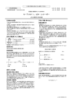
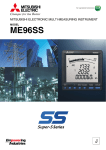
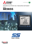
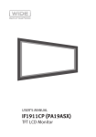
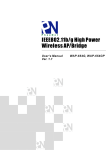
3. Display and Button Functions
Environmental protection use time limit
Display
Function of operation button
2
1
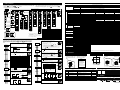
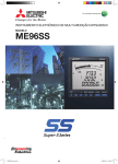
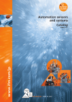
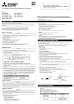
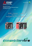
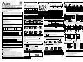
5. Wiring Diagram
RESET
SET
MITSUBISHI Electronic Multi-Measuring Instrument
User’s Manual (Simple version)
Types ME96SSH-MB, ME96SSR-MB, ME96SSE-MB
1. Safety Precaution
(Always read these instructions before using this equipment)
For personnel and product safety please read the contents of these operating
instructions carefully before using. Please save this manual to make it accessible when
required and always forward it to the end user.
HAZARD SYMBOLS
Read these instructions carefully and look at the equipment to become familiar with the device
before trying to install, operate, service or maintain it. Terminal of control power (MA, MB) and
voltage inputs (P1, P2, P3, PN) have hazards of electric shock, explosion, or arc flash. Turn off
power supplying this device and the equipment in which it is installed before working on it.
Note: This symbol mark is for China RoHS.
Contained name of six hazardous substances
Parts name
Printed wiring
board
Electronic
parts
Case
LCD
Terminal
block
Contacts
Others
○
Installation instructions
This instrument should be installed and used by a qualified electrician.
The instrument must not be powered and used until its definitive assembly on the cabinet’s door.
Verify the following points;
Auxiliary power supply and measuring ratings.
Auxiliary power supply 100-240V AC ±15% (50-60Hz) 8VA
100-240V DC +15% -30% 5W
3-PHASE 4-WIRE : MAX277V(L-N)/480V(L-L) Category Ⅲ
Ratings Voltage
3-PHASE 3-WIRE(DELTA) : MAX220V(L-L)
3-PHASE 3-WIRE (STAR): MAX440V(L-L)
1-PHASE 3-WIRE : MAX220V(L-N)/440V(L-L)
1-PHASE 2-WIRE(DELTA) : MAX220V(L-L)
1-PHASE 2-WIRE(STAR) : MAX440V(L-L)
×
○
○
○
○
○
○
○
○
○
○
○
○
○
○
○
○
○
○
○
○
○
○
○
○
○
○
4
Set Button
+/– Button
8
○ : press
16
◎ : press on over 2 seconds
SET
15 14 13
1
2
3
4
5
6
7
8
materials of the corresponding material doesn’t exceed the standard that
provides.
× : It means the content of a poisonous hazardous substance in homogeneous
materials of the corresponding parts exceeds the standard that provides.
Phase change
Button
Maximum/Minimum
Button
Display change
Button
― : press simultaneously
Reset Button
5
7
○: It means the content of a poisonous hazardous substance in all homogeneous
12
LEAD status
LAG status
Scale of the bar graph
Outside range
Index indicator
Bar graph status
Digital status
Unit
4. 1 Display Change
−
+
RESET MAX/MIN PHASE DISPLAY
9
11 10
○
○
9 Metering status
10 Harmonics status
11 Communication status
12 Alarm status
13 Clock status
14 Test status
15 Stepup mode status
16 Digital
○
○
○
○
◎
◎
◎
◎
Function.
Display changes.
Phase changes.
Mode changes to the max./min.
display and the instantaneous display.
An alarm conditions is individually
canceled.
The item expressed with the bar graph
is changed.
All the alarm conditions is canceled.
The display of Setting mode appears.
The display of Set value confirmation
mode appears.
(Note)
Note. In case of a circuit which is wired from the delta connection of a 3-phase 3-wire type or a circuit of a transformer of a
1-phase 2-wire type, the maximum rating is “AC220V”
In case of a circuit which is wired from a 3-phase 4-wire type, the star connection of a 3-phase 3-wire type or a 1-phase
3-wire type, the maximum rating is “AC440V”
3-phase 4-wire circuit / MODBUS RTU communication
R
4. 5 Alarm Display and How to Cancel
By pressing DISPLAY , the measurement display will switch over.
Example of display change (display pattern:P01/phase wire : 3-phase 4-wire)
DISPLAY
DISPLAY
DISPLAY
Automatic
(Auto)
First display
Second display
Third display
Manual
(HoLd)
By pressing PHASE , the current phase and the voltage phase will switch over.
Example of display change (phase wire : 3-phase 4-wire)
Example of phase switching (Phase wire System: 3-phase 4-wire)
PHASE
Current average
Active Power (total)
Voltage average (between phases)
T/R+, T/R-, Ter terminals
CC-Link communication
DA,DB,DG terminals
DI1, DI2, DI3, DI4, DI COM, DI+, DI-,
DI1+, DI1-, DI2+, DI2-, DI3+, DI3-, DI4+, DI4-, DI5+, DI5- terminals
DO1+, DO1-, DO2+, DO2- terminals
CH1+, CH1-, CH2+, CH2-, CH3+, CH3-, CH4+, CH4- terminals
max 35V DC
C1A/A1, C1B/COM1, C2A/A2, C2B/COM2 terminals
The instrument is to be mounted on a panel. All connections must be kept inside the cabinet.
Tighten the terminal screws with the specified torque and use the suitable pressure connectors and suitable wire size.
When wiring the instrument, be sure that it is done correctly by checking the instrument’s wiring diagram.
Be sure there are no foreign substances such as sawdust or wiring debris inside the instrument.
Do not drop this instrument from high place. If you drop it and the display is cracked, do not touch the liquid
crystal or get it in your mouth. If the liquid crystal is touched, wash it away at once.
In order to prevent invasion of noise, do not bunch the control wires or communication cables with the main
circuit or power wire, or install them close to each other. The distance between communicational signal lines,
input signal lines and power lines, high voltage lines running parallel to each other are shown below.
Length
Conditions
Below 600V, or 600A power lines
30cm or more
Other power lines
60cm or more
Protective conductor terminals for mains circuits shall be at least equivalent in current-carrying capacity to the mains supply terminals.
If the protective conductor terminals is also used for other bonding purposes, the protective conductor shall be
applied first and secured independently of other connections.
Operation instructions
CAUTION
When the external terminals are connected to the external equipments, the instrument and the external equipments
must not be powered and used until its definitive assembly on the cabinet’s door.
The rating of the terminal of the external equipment should satisfy the rating of the external terminal of this instrument.
Maintenance instructions
CAUTION
Do not touch the terminals while all the circuits connected to this instrument are alive.
Do not disassemble or modify the instrument.
Do not contact a chemical dust cloth to the instrument for a long time, or do not wipe it with benzene, thinner, alcohol.
Wipe dirt off the surface with a soft dry cloth.
Check the following points, (at the cycle of six months to one year)
Condition of the appearance
Unusual sound, a smell, and generation of heat
Condition of the wiring and the attachment
Condition of the display
Storage conditions
Ambient temperature :-25 to +75°C,average day temperature 35°C or less
Humidity : 0 to 85%RH,non condensing.
Atmosphere without corrosive gas,dust,salt,oil mist.
A place without excessive shocks or vibration.
Do not expose to rain and water drips.
Do not expose to direct sunlight.
An area in where no pieces of metal and an inductive substance disperse.
Disposal
A battery is not used for this product.
Guarantee
The period of guarantee is earlier date of either 18 months from the manufacture date or 1 year from the sale date,
except in the case that the failure has been caused by bad handling of the product, provided that it has been installed
according to the manufacture’s instructions.
FCC
This instrument complies with part 15 of the FCC Rules. Operation is subject to the following two conditions: (1)
This instrument may not cause harmful interference, and (2) this instrument must accept any interference
received,including interference that may cause undesired operation.
Please contact the service network when the equipment has a breakdown or abnormality.
PHASE
Current phase 1
Active Power phase 1
Voltage phase 1N
Display
PHASE
Current phase 2
Active Power phase 2
Voltage phase 2N
Current phase 3
Active Power phase 3
Voltage phase 3N
PHASE
PHASE
Alarm condition
ALARM , HI or LO
are blink
Normal condition
Closed
Opened
Output
(Alarm relay contact)
Fourth display
4. 2 Phase Change
P1, P2, P3, PN terminals
MODBUS RTU communication
Display and Alarm output, How to cancel
Alarm condition:If a measurement value exceeds an alarm value, the parts of
display blink and an alarm relay contact closed.
Alarm cancel method
DISPLAY
Provide the basic insulation externally at the current input terminals.
Voltage-measuring and current-measuring circuit terminals should be permanently connected.
Others
When disposing of this product, treat it as industrial waste.
○
○
○
○
○
○
○
3
MA, MB terminals
5A (via current transformer) (max 30V AC) Category Ⅲ +C1, C1, +C2, C2, +C3, C3 terminals
Current
Frequency 50/60Hz
Digital output
Analog output
Pulse/Alarm output
○
○
○
○
○
○
○
DISPLAY
Display
State usually
ALARM , HI or LO ALARM , HI or LO
cancel
are blink
are lighting
Output
(Alarm relay contact)
Closed
Closed
State
usually
Opened
① Auxiliary power supply 100-240VAC or 100-240VDC
② Fuse : 0.5A
※1 For a low voltage circuit,grounding of the secondaly sides of VT and CT in not necessary.
※2 Do not connect to NC terminal.
3-phase 3-wire 2CT circuit
3-phase 3-wire 3CT circuit
Alarm cancel
Automatic
If a measurement value falls below an alarm value, alarm is automatically canceled.
Manual
After the measurement value falls below an alarm value, alarm is maintained.
(HoLd)
The element of alarm is displayed and when RESET is pressed, alarm is canceled.
Alarm delay time
If the condition that the limit was exceeded continues more than the delay
time, it will be in the alarm condition.
The alarm output by rush current can be prevented.
4. 6 Harmonics Display
PHASE
Current phase 3
Active Power phase 3
Voltage phase 31
PHASE
Current phase 2
Active Power phase 2
Voltage phase 23
PHASE
Current phase 1
Active Power phase 1
Voltage phase 12
Current average
Active Power (total)
Voltage average (between lines)
4. 3 Bar Graph Display
Measurement item to be displayed on bar graph can be selected. By displaying
others than the measurement items digitally displayed, 4 elements can be
displayed at once.
Explanation of bar graph
In the bar graph, measurement elements shown by “ ” or “
” are
displayed.
As for voltage, current, active power, reactive power, power factor,
frequency, they can be displayed on the bar graph even if they are not set to
display pattern.
Selection of bar graph
Press or , to select measurement elements to be displayed the bar graph.
Harmonic RMS value and distortion ratio can be displayed.
Measurement items
ME96SSH-MB:Harmonic total,From 1st to 31st(only odd number)
ME96SSR-MB:Harmonic total,From 1st to 13th(only odd number)
Degree change
and
are pressed, harmonic degree change.
When
When PHASE is pressed, harmonic phase change.
The maximum values and minimum values are displayed.
Display of maximum value and minimum value
When MAX/MIN is pressed, the display is changed into the maximum
value and minimum value display. And when MAX/MIN is pressed, the
display changes back to the instantaneous value display.
Reset the maximum value and minimum value
When RESET is pressed for 2 seconds or more, the displayed maximum
value and minimum value can be reset.
When RESET and
are pressed simultaneously for 2 seconds or more, all
the maximum values and minimum values are reset.
6. Check on Your Delivery
4. 7 Expanded Counting Display
Active energy(Imported):Example of switching 012,345,678,901,234.567Wh
Press + and - simultaneously for 2 seconds
CC-Link communication
Quantity
Specifications
1
A3 size
Attachment lug
(with screw)
2
This manual is a simple version. Please contact our Service Network for a detailed version of User’s Manual.
Lower digit magnification display
Unit:non
Unit:k
Wh,varh and VAh zero reset
When SET , RESET and PHASE are pressed simultaneously for 2
seconds, the measurement value of active energy(Wh) ,reactive
energy(varh) and apparent energy(VAh)are reset.
(This is effective only in the instantaneous value display.)
Example for display
ME96SSH-MB or
ME96SSR-MB
Analog output
Pulse output
Alarm output
DI, DO
ME-4210-SS96
ME-0040C-SS96
DA
DB
DG
SLD
FG
SLD
DG
DB
DA
Dl1
Dl2
Dl3
Dl4
DlCOM
CC-Link
Communication
CC-Link
Communication
ME-0052-SS96
Analog output CH1
Analog output CH2
Analog output CH3
Analog output CH4
Pulse output1/Alarm output1
Pulse output2/Alarm output2
Digital input
DC24V
Protective
Bonding
Reactive energy
(Imported lag)
Reactive energy
(Imported lead)
Reactive energy
(Exported lag)
DI1-,DI2-,DI3-,DI4-,DI5- are connected inside.
Reactive energy
(Exported lead)
7. Handling precautions
Parts name
User’s manual
(this document)
1-phase 3-wire circuit
Active energy,reactive energy and apparent energy display
Active energy and reactive energy,apparent energy are display on unit
switching and the lower stage.
Unit:M
4. 4 Maximum Value and Minimum Value Display
1-phase 2-wire circuit
{
{
{
{
{
{
{
Normal service conditions
Use the instrument in an environment that meets the Normal service conditions as following points:
Ambient temperature : -5 to +55°C, average day temperature 35°C or less.
Humidity : 0 to 85%RH, non condensing.
Altitude : 2000m or less
Pollution Degree : 2 or less
Atmosphere without corrosive gas, dust, salt, oil mist.
Indoor use
Transient over voltage 4000V or less
A place without excessive shocks or vibration.
Do not expose to rain and water drips.
Do not expose to direct sunlight.
An area in where no pieces of metal and an inductive substance disperse.
Do not expose to strong electromagnetic field and ambient noises.
Digital input
Poisonous hazardous substance or element
Hg
Cd
Cr(VI)
PBB
PBDE
Pb
PHASE
4. Operation
CAUTION
Indicates that incorrect handling may cause hazardous conditions. Always follow the instructions because they are
important to personal safety. Otherwise, it could result in electric shock, fire, erroneous operation, and damage of the
instrument. If the equipment is used in a manner not specified by the manufacturer, the protection provided by the
equipment may be impaired.
R
3
4
6
Rating voltage for every phase wire system
MAX/MIN
Precautionary note written in Korean
Distributors and users must understand that this product meets the electromagnetic
compatibility requirements and is designed for industrial use (Class A). Do not use the
product in a residential area.
CAUTION
1.Do not connect with hot-line
2.Do not use in the condition that the secondary circuit of CT is opened.
3.Do not use in the condition that the secondary circuit of VT is short-circuited.
4.The wire size has to be suited for the rated current and rated voltage.
Terminals of +C1,C1,+C2,C2,+C3,C3:AWG24 to 14
(For UL recognized: Single wire of AWG22 to 16)
Terminals of instrument main body(except for +C1,C1,+C2,C2,+C3,C3 terminals ):AWG24 to 14
(For UL recognized: AWG24 to 18)
When using a stranded wire, use a ferrule.
Note 1: This is the notification for the KC mark (Korea Certification)
Please see the back
10. Specification
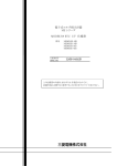
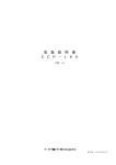
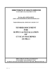
8. Setting Diagram
Type
• How to access the setting items.
Current (A)
3-PHASE 4-WIRE, 3-PHASE 3-WIRE(3CT, 2CT), 1-PHASE 3-WIRE, 1-PHASE 2-WIRE (common)
AC5A, AC1A (common)
3-PHASE 4-WIRE:max AC277/480V
3-PHASE 3-WIRE:(DELTA) max AC220V, ( STAR) max AC440V
1-PHASE 3-WIRE:max AC220/440V
1-PHASE 2-WIRE:(DELTA)max AC220V, (STAR) max AC440V
50-60Hz (common)
Measurement Item
ME96SSH -MB
ME96SSR-MB
A1, A2, A3, AN, A AVG
±0.2%
±0.1%
Current Demand (DA)
DA1, DA2, DA3, DAN, DA AVG
Voltage (V)
V12, V23, V31, VAVG (L-L), V1N, V2N, V3N, VAVG (L-N)
Active Power (W)
Reactive Power (var)
Apparent Power (VA)
Power Factor (PF)
Frequency (Hz)
Active Energy (Wh)
Reactive Energy (varh)
Apparent Energy (VAh)
Harmonic current (HI)
Harmonic voltage (HV)
Rolling Demand(DW)
Periodic Active Energy (Wh)
Operation time (h)
Analog output response time
Measuring
Instantaneous Value
Method
Demand Value
Type
W1, W2, W3, ΣW
±0.5%
±0.2%
var1, var2, var3, Σvar
±0.2%
±0.5%
VA1, VA2, VA3, ΣVA
±0.2%
±0.5%
PF1, PF2, PF3, ΣPF
±1.0%
±2.0%
Hz
±0.2%
±0.5%
Imported, Exported
class0.5S(IEC62053-22)
class1.0(IEC62053-21)
Imported Lag, Imported Lead,Exported Lag, Exported Lead
class2.0(IEC62053-23)
class2.0(IEC62053-23)
Imported + Exported
class2.0
―
±2.0%
±2.0%
Only odd number
(1 to 31)
(1 to 13)
Only odd number
Rolling Block , Fixing Block
±0.2%
―
class1.0(IEC62053-21)
Periodic Active Energy 1, Periodic Active Energy 2
class0.5S(IEC62053-22)
Operation time 1, Operation time 2
(Reference)
(Reference)
2 s or less (HI and HV:10s or less)
A・V:RMS calculation,W・var・VA・Wh・varh・VAh:Digital multiplication, PF:Power ratio calculation,Hz:Zero-cross, HI・HV:FFT
DA:Thermal type calculation , DW:Rolling Demand calculation
LCD with backlight
Upper stage display:6 digits, Middle stage display:6 digits, Lower stage display:6 digits
A, DA, V, W, var, VA, PF:4 digits DW , Hz:3 digits Wh, varh, VAh:9 digits(6 digits or 12 digits possible)
Harmonic total distortion ratio:3 digits Harmonic RMS value:4 digits Operation time:6 digits Digital input/output:I/O
21 Segment-Bar graph, 22 Segment - Indicator
0.5s, 1s
MODBUS® RTU communication
ME-4210-SS96, ME-0040C-SS96, ME-0052-SS96 (Only ME96SSH-MB, ME96SSR-MB)
DC4 to 20mA
(0 to 600Ω)
No -voltage ‘a’ contact
DC35V, 0.1A
0.125s, 0.5s, 1.0s
DC24V(DC19 to 30V), 7mA or less
30ms or longer
No-voltage ‘a’ contact
DC35V, 0.2A
Non volatile memory(Items:Setting value, MAX/MIN value, Active/Reactive/Apparent energy, Periodic Active Energy, Rolling Demand,
Operation time)
0.1VA/phase, 0.2VA(at direct input 220V)
0.1VA/phase
7VA(AC110V), 8VA(AC220V), 5W(DC100V)
AC100-240V(±15%), DC100 to 240V (-30% +15%)
0.5kg
96(H)×96(W)×86(D)
Embedding attachment
-5 to +55℃(average temperature:35℃ or less per day) , 0 to 85%RH, non condensing
-25 to +75℃ (average temperature:35℃ or less per day), 0 to 85%RH, non condensing
Rating
Display
Setting Menu End
Setting Menu 2
Setting Menu 1
Setting Menu 3
Frequency
Setting Menu 5
Setting Menu 4
Setting Menu 7
Setting Menu 6
Item
※3
Setting Value Confimation Menu 9
Setting Menu 8
※2
Phase
End Display
Current scale
wire syste
Save the setting.
Product
display
Alarm item
Analog output 1
Alarm value
Analog output 2
Periodic Active
Operation time
Energy display
display
Periodic Active Energy
Operation time
switchover setting
count target
Rolling Demand
Operation time
display
value
※3
Test Mode
Communication
method selection
Display
Pattern
Voltage scale
VT/direct
CANCEL Display
voltage
MODBUS®RTU
CC-Link
address
Station number
MODBUS®RTU
CC-Link
baud rates
Version
display
Active power
scale
Backlight
brightness
Alarm delay
Reactive
Backlight
auto off
Alarm cancel
Analog output 3
time
Measurement elements
※1
Cancel the settings.
baud rates
Automatic migration.
Power factor
Frequency
The instrument is reset
or
power scale
CC-Link
version
MODBUS®RTU
parity
Display
update time
Rollingdemand
Phase display
time constant setting
setting
Analog output 4
method
Digital input
IEC mode
during alarms
/output display
setting
Expanded
Motor starting
Digital input
counting
current delay time
reset method
Harmonics
display
oputput function
scale
Back light flickers
Output Limit
Display
CT current
Factory default setting
Time constant for
CC-Link
MODBUS®RTU
Rolling demand
Password Protection Display
Reset
stop bit
Time constant for
current demand
<With ME-0040C-SS96 only>
Password
Action
Arrow in Figure
Pulse/Alarm
Button operation
Shift from the operation mode to the setting mode.
SET
Shift from the operation mode to the set value confirmation mode.
setting change
Example of Setting Value
Example of Setting Mode
ON
Omitted infigure
Blinking
or
+
Shift to the End screen.
SET
※1.A password input is needed when a password protection
setting is validated, and get in the setting mode from
the operation mode.
Memorize the setting contents, and go back to the operation mode.
SET
Cancel the settings.
SET
※2.For Setting Value Confirmation, it returns to Operation Mode.
Skip remaining setting items during setting.
SET
※3.This is not display in Setting Mode.
Set values return to the factory default value.
RESET
Shift from the operation mode to the password protectionmode.
RESET
Select "CANCEL."
Press it.
-
Press it several times.
Press it.
Press it.
or
+
Press it several times.
Press it.
DISPLAY
Select a set value.
Press them simultaneously
Press it for 2 seconds.
-
SET
Go back to the previous setting item.
Confirmation Mode
RESET
or
+
Get into each setting screen. Shift to the next setting item.
Pulse output
+
SET
Select the menu number to set or “End” .
-
Press it.
Maximum Number of
Display Digits or
Segment Number
Power Failure Compensation
Press it.
Press it for 1 seconds.
+
+
PHASE
Press it for 2 seconds.
PHASE
Press it for 2 seconds.
In this setting menu 1, setting the basic contents as following for correct measurement .
In the operation mode, after pressing the SET and the RESET simultaneously for 2
seconds or more, the following operation becomes available. An underline shows the initial
value.
Set the setting menu number to “1”. (Set as shown in the right
display.)
⑥VT primary
voltage
Setting menu
SET
DISPLAY
SET
① Set the phase wire system.
3P4
3P3.2CT
3P3.3CT
1P3.1N2
1P3.1N3
1P2
① Phase wire
:
:
:
:
:
:
3 -phase 4-wire
3 -phase 3-wire(2CT)
3 -phase 3-wire(3CT)
1 -phase 3-wire(1N2)
1 -phase 3-wire(1N3)
1 -phase 2 -wire
⑥ Set the primary voltage value of VT in the case of using VT.
If you set “no” on set up No.③, this display does not appear.
Initial value
3-phase 3-wire or 1-phase 2-wire: 10000V
3-phase 4-wire : 200V
VT
CT
Auxiliary power
Auxiliary power
Weight
Dimension
Attachment Method
Operating temperature/humidity
Storage temperature/ humidity
VA Consumption
5A
1A
DISPLAY
: Display is made at this display setting.
: Set by the setting menu 4.
: Select “P00”, and set display sequence and display position.
DISPLAY
SET
○
△
○
△
△
Apparent Energy
○
○
○
○
○
□
○
□
○
□
○
□
○
□
○
○
○
□
□
○
□
○
□
○
○
○
△
△
△
△
△
△
△
○
△
Operation time
○
Reactive Energy (Special)
Apparent Energy
Reactive Energy
Active Energy(Exported)
○
Digital Input/Output
○
○
○
Active Energy(Exported)
○
○
○
Active Energy (Imported)
○
○
○
△
Harmonic Current/ Voltage
□
○
○
○
○
Rolling Demand
□
○
○
○
○
○
Periodic Active Energy
○
○
○
○
Active Energy(Imported)
○
○
○
○
○
○
○
○
□
Frequency
○
○
○
○
○
○
○
○
□
○
○
○
○
○
Apparent Power
○
○
○
○
○
○
○
○
□
○
○
○
○
○
Reactive Power
○
○
○
○
Power Factor
○
○
○
○
Voltage
○
○
○
○
Active Power
Current Demand
N Phase Current Demand
N Phase Current
SET
P01
P02
P03
P04
P05
P06
P07
P08
P09
P10
P11
P12
P13
P00
Current
Display Pattern
② Display pattern
.
• The setting digit can be moved to right by the SET .
⑧ CT primary
current
Additional Screen
△
△
△
△
△
△
△
△
△
△
△
△
△
△
△
△
△
△
△
△
△
△
△
△
△
△
△
△
△
△
△
△
△
△
△
△
△
△
△
△
△
△
△
△
△
△
△
△
△
△
△
△
△
△
△
△
△
△
△
△
△
△
△
△
△
△
△
△
△
△
• The setting digit can be moved to left by the DIAPLAY .
• The number of settable digits is significant 3 digits. Setting is available in the range
from 1A to 30kA (30000A).
If it is set to other range than 1A - 30kA, error display (E05) appears. At the moment of the error
display, press the SET , and review the set value, and set it once again.
• When the SET is pressed at the most lower digit, the setting item goes to the next one.
DISPLAY
SET
⑨ Set the frequency.
50Hz
⑨ Frequency
SET
ME-4210-SS96
ME-0052-SS96
ME-0040C-SS96
Analog output
4ch
—
—
Pulse/Alam output
2ch
—
—
Digital input
1ch
5ch
4ch
Digital output
—
2ch
—
Communication
—
—
CC-Link
60Hz
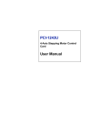
Installation on panel
③ Using VT/
direct input
DISPLAY
SET
Initial content
3- phase 3-wire or 1 phase 2-wire:using VT
3- phase 4-wire : direct input
<When ①phase wire system is set to single-phase 3-wire>
Use only for direct input. This setting will be skipped.
DISPLAY
④ Set the rated voltage for scaling of the bar graph.
If you set “YES” on set up No.③ , this display does not appear.
SET
(a)For 3- phase-4 wire
(phase to neutral voltage / phase to phase voltage)
④ Direct voltage
(1)Interval time constant
Setting step
1min
DISPLAY
240/415V
254/440V
277/480V
63.5/110V
100/173V
110/190V
220/380V
110/220V
220/440V
(c)For 1- phase 3- wire(1N2,1N3)
(phase to neutral voltage / phase to phase voltage)
SET
110V
220V
Set the secondary voltage values of VT in case of using VT.
⑤ If you set “no” on set up No.③, this display does not appear.
⑤VT secondary
voltage
(a)For 3- phase 4-wire
(phase to phase Voltage)
63.5V
100V
110V
115V
120V
⑪ Time constant for
current demand
Setting step
1min
Country / Region
China
0 second
40 seconds
3 minutes
7 minutes
15 minutes
10 seconds
50 seconds
4 minutes
8 minutes
20 minutes
20 seconds
1 minute
5 minutes
9 minutes
25 minutes
30 seconds
2 minutes
6 minutes
10 minutes
30 minutes
Indonesia
Korea
Philippines
Taiwan
SET
Note) Even when the display pattern not display the current demand, this screen appears. If the current demand is
not necessary, press the SET as it is.
According to the setting diagram, save the changed contents, or
continue to the other set up menu.
Setting menu
Thailand
Vietnam
Company
Mitsubishi Electric Automation
(CHINA) Ltd.
It can be installed to
a panel of thickness
:1.6-4.0mm
Note : Install the Optional Plug-in Module after it turns off power.
14. Standards
Address
No. 1386 Hongqiao Road, Mitsubishi Electric Automation Center
Shanghai China, 200336
Telephone
Standard
Safety
Europe
+86-21-2322-3030
P.O.Box 5045 Kawasan Industri Pergudangan,
Jakarta, Indonesia
+62-(0)21-6610651-9
Mitsubishi Electric Automation Korea
Co., Ltd
1480-6, Gayang-Dong, Gangseo-Gu, Seoul, Korea
+82-2-3660-9572
Edison Electric Integrated, Inc.
24th Fl. Galleria Corporate Center, Edsa Cr. Ortigas Ave.,
Quezon City Metro Manila, Philippines
+63-(0)2-634-8691
Setsuyo Enterprise Co., Ltd
6th Fl., No.105, Wu Kung 3rd, Wu-Ku Hsiang,
Taipei, Taiwan, R.O.C.
+886-(0)2-2298-8889
United Trading & Import Co., Ltd.
77/12 Bamrungmuang Road, Klong Mahanak,
Pomprab Bangkok Thailand
+66-223-4220-3
CTY TNHH-TM SA GIANG
10th Floor, Room 1006-1007, 255 Tran Hung Dao St.,
Co Giang Ward, Dist 1, Ho Chi Minh City, Vietnam
+84-8-8386727/28/29
P. T. Sahabat Indonesia
② The Optional Plug-in
Module is installed.
① The option cover is
removed.
13. Service Network
440V
(b)For 3- phase 3-wire (2CT, 3CT)
or 1 phase 2-wire
100V
110V
220V
Setting range
1 to 60 (min)
・Error display (E05) appears when the interval time constant
is set to a value that is not dividable by the subinterval time
period. After that, please press SET , review the setting value
and it once again.
・Even when the display pattern not display the rolling demand,
this screen appears. If the rolling demand is not necessary,
press the SET as it is.
⑪ Set the time constant for calculating current demand.(only ME96SSH-MB,ME96SSR-MB)
(b)For 3- phase 3-wire
(2CT, 3CT) or 1- phase 2-wire
―
―
―
(Reference)
Installation of Optional Plug-in Module
Panel hole dimensions
Please do not tighten too
strongly to prevent panel and
screw from breaking.
Tightening torque for this
product: 0.3N • m∼0.5N• m
(Half the torque applied
normally for this type
of screw)
Also, please tighten the upper
and lower screws at the same
time.
(2)Subinterval time constant
YES : using VT
no : direct input
±0.5%
―
―
±2.0%
±0.5%
class1.0( IEC62053-21,Only Imported Lag)
―
―
Note. The optional plug-in module can be installed in the ME96SSH-MB, the ME96SSR-MB.
① The attachment lug is
② The screw of the
installed in four holes of the
attachment lug is tightened,
top and bottom of the main
and it fixes to the panel.
body.
Note
Note1. The scale value of the frequency of the bar graph display
is changed, too.
Note2.Scale of the analog output is changed, too.
Setting range
1 to 15 to 60(min)
⑩ Time constant for
rolling demand
③ Set the using VT or direct input (without VT).
±0.1%
±0.5%
Model name
I/O Parts
⑩ Set the interval time constant for rolling demand.(Only ME96SSH-MB)
DISPLAY
―
±0.2%
⑧ Set the primary current value of CT. (The initial value is 5A.)
• From top digit, select the value of the flickering digit by + and –
In the case of ME96SSH-MB
DISPLAY
SET
±0.2%
12. Installation
② Set the display pattern. (Initial content: P13)
Note:
ME96SSE-MB
±0.5%
±0.1%
11. Optional Plug-in Module
• From top digit, select the value of the flickering digit by + and – .
• The setting digit can be moved to right by the SET .
• The setting digit can be moved to left by the DISPLAY .
• The number of settable digits is 3 digits. Setting is available in the range from 60V to 750kV. (750000V)
If it is set to other range than 60V - 750kV, error display (E05) appears. At the moment of the error
display, press the SET , and review the set value, and set it once again.
• When the SET is pressed at the most lower digit, the setting item goes to the next one.
⑦ Set the secondary current value of CT.
⑦CT secondary
current
Number of display digits
Bar graph
Display updating time interval
Communication Specification
Accessible option unit
Analog output
Output specification
The kind of switch
Pulse/Alarm output
Contact Capacity
Pulse width
Contact Capacity
Digital input(DI)
Signal width
The kind of switch
Digital output(DO)
Contact Capacity
9. Setting
DISPLAY
Voltage
Setting Mode or Setting Value Confirmation Mode
Operation Mode
ME96SSH-MB, ME96SSR-MB, ME96SSE-MB
Phase wire system
Current
1 Press the SET button and the RESET key simultaneously for 2 seconds to get in the setting mode. 4 After completion of setting, select ‘End’ in the setting menu and press the SET button.
5 When the End display appears, press the SET button once again.
2 Select a setting menu number by + or – button.
3 Change the contents in each setting menu.
CE, as per EN61010-1
USA and Canada
cRUus as per UL61010-1, IEC61010-1 (Edition 3.0)
Installation Category
Ⅲ
Measuring Category
Ⅲ
Pollution Degree
2
EMC
EN 61326-1, EN 61000-3-2, EN 61000-3-3
15. Symbols
1
direct current
2
LM305Z386H01
Alternating current
3
Protective conductor terminal
IB63803
Please see the back