1
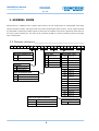
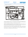
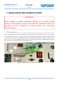
MO1001 Optical Node
Installation manual
Apr, 2015
Installation manual
IM-1402-MO1001-EN-v2.odt
MO1001
Apr, 2015
Contents
1. GENERAL GUIDE............................................................................................. 2
1.1 Ordering information .......................................................................................................2
1.2 Outside contstruction ......................................................................................................3
1.3 Inside construction ..........................................................................................................5
2. INSTALLATION AND OPERATION GUIDE............................................................6
2.1 Installation .......................................................................................................................6
2.1.1 Fixing the node into a cabinet..................................................................................7
2.1.2 Fixing the node onto a pillar.....................................................................................7
2.1.3 Building in the modules, connecting optics and RF..................................................8
2.1.4 Setting up the slope and level at the output............................................................9
3. MONITORING................................................................................................ 10
3.1 MO1001 optical node in monitoring system ..................................................................10
3.1.1 Using the MO1001 with monitoring option in HMS network...................................11
3.1.2 Monitored values in the MO1001 optical node.......................................................11
3.1.3. Monitoring in ComMon system..............................................................................14
3.1.4. Getting the most important value at the optical node location.............................17
1
MO1001
Installation manual
IM-1402-MO1001-EN-v2.odt
Apr, 2015
1. GENERAL GUIDE
MO1001 device is COMTECH Ltd's compact optical node in die-cast housing with an exchangeable return path
optical transmitter module. This optical node has a built-in forward path optical receiver. The RF signal is boosted
by 1GHz GaAs or GaN Power-Doubler hybrids. At the end of the amplifier chain works a high-level output that can
be used for power inserting too. The node can be connected to HMS or Comtech monitoring system by the right
type of transponder.
1.1 ORDERING
M O
1
0
INFORMATION___________________________________________
0
1
X
X
-
X
Amplifier-module type
X
-
X X
-
Laser type
X
X X X
Wavelength
GaAs
0N Without laser!
1270
1270 nm
D
GaN
1F FP laser (1mW)
1290
1290 nm
2D DFB laser (2mW)
1310
1310 nm
2C CWDM laser (2mW)
1330
1330 nm
4C CWDM laser (4mW)
1350
1350 nm
1370
1370 nm
1390
1390 nm
1410
1410 nm
R
Remote powered
L
Local powered
Type of the diplex filter
30
Internal DF 30/47 diplex filter
1430
1430 nm
65
Internal DF 65/85 diplex filter
1450
1450 nm
Internal DF 85/105 diplex filter
1470
1470 nm
1490
1490 nm
1510
1510 nm
1530
1530 nm
1550
1550 nm
1570
1570 nm
1590
1590 nm
1610
1610 nm
85
X
(CWDM)
C
Powering
-
Type of the optical connector
SA
SC/APC (Recommended type)
FA
FC/APC
EU
EURO-2000
Wavelength
1310
2
(FP and DFB)
1310 nm
X
MO1001
Installation manual
IM-1402-MO1001-EN-v2.odt
1.2 OUTSIDE
Apr, 2015
CONTSTRUCTION___________________________________________
MO1001 optical node housing consists of two parts. In the bottom part there are three bays. The biggest one
contains the RF mainboard with the RF as well as the optical ports. Behind this a medium sized bay contains the
local or remote powered switching-mode power supply and a small bay in which the optional monitoring
transponder can be placed. The lower and upper part of house can be fixed to each other by a screw. Between the
surfaces there is a waterproof rubberfiller.
Figure 1 shows the open device's main parts (Attention! Device in picture is just an example so there could be
differences between this and your device):
Figure 1: MO1001 optical node view from above
3
MO1001
Installation manual
IM-1402-MO1001-EN-v2.odt
Apr, 2015
The MO1001 optical node is delivered with a chosen type of return path transmitter. On demand the device can be
upgraded by changing the module with a higher power or with a different wavelength one. This can be done by
removing metal lid of the RF bay. It is strongly recommended to let th e above detailed procedure do by Comtech
or by a contracted repair partner of Comtech. In case of unauthorized upgrade of the device the internal optical
patchcables can be injured and the EMC sensitive parts can be damaged. In such a case the warranty voids!
On Figure 2 you can see the open device's main parts (Attention! Device in picture just an example so maybe
there are differences between this and your device):
Switching mode PSU
Multifunctional display
Monitoring transponder (optional!)
FWD testpoint
Output splitter
(SD module)
RF ports
Function selector/ Function LEDs
Level buttons
Enter button
OMI indicator LEDs
Return path optical
Status LED
Jumpers for switching
on/off a 20 MHz HPF
Optical ports
Figure 2: MO1001 optical node's physical construction
4
REV testpoint
MO1001
Installation manual
IM-1402-MO1001-EN-v2.odt
1.3 INSIDE
Apr, 2015
CONSTRUCTION_____________________________________________
Figure 3 shows the inside construction of MO1001:
SUPPLY
230 V AC
AC FUSE
AC IN
SWITCHING POWER SUPPLY
MO1001L
locally powered
STATUS MONITORING SYSTEM
DC IND
60V AC
MO1001R
remote powered
OPT. INPUT
SURGE
PROT
DC TP
AC TP
+ 24V DC
ATT
EQ (6dB)
ATT
EQ (0...16dB)
OUT1
ATT
O
E
FC/APC,
SC/APC,
EURO2000
AC
BYPASS
OLC
SD
H
SP
or
DC
DF
L
Display
TP
OPT. OUT
LPF 65
MONITORING
OUT
HPF 20
0 db
-6 dB
-60 dB
E
F2
ATT
FC/APC,
SC/APC,
EURO2000
RF
IN
OMI
DET.
LASER
CONTROL
AC FUSE
10 A
TP
-30dB
RSW
O
F1
AC FUSE
10 A
AC
BYPASS
µP Controller
NOISE
DET.
6MHz
OUT 2
RF
OPT.
PWR
OMI
3% 10% 30%
SURGE
PROT
Figure 3: Inside construction of MO1001
The node has 1 high-level RF output. You can also connect here the remote AC power (at MO1001R type) via a
coax cable. This output has a Test Point too – the measured level is -30dB correlated to the output signal level.
The signal can be splitted into two simmetrically or asymmetrically by the SD module.
The device can be delivered with different type of return path module with or without LASER transmitter. This
module communicates with monitoring system also and can be adjusted via optical node's microcontroller with
the function selector / level buttons. Also this module has a Test Point for the return path.
The forward path optical receiver is followed by an automatically adjusted amplifier an equalizer and an
attenuator module. At the end of the RF chain a changeable diplex filter is placed. After these in the transmission
line the signal goes to the diplex filter, the available breakponts are 30/47 MHz and 65/85MHz. (85/105 MHz is
under construction, For more information please contact Comtech Ltd.)
5
Installation manual
IM-1402-MO1001-EN-v2.odt
MO1001
Apr, 2015
2. INSTALLATION AND OPERATION GUIDE
ATTENTION!
Device contains an optical transmitter (ROT-B) and a built-in optical
receiver. Avoid exposure to beam. Shut down the transmitter before any
operation on device. Connection of non-used cables close with dustprotection plug!
2.1 INSTALLATION___________________________________________________
After unpacking please check the node configuration. Open the top of cast after loosen the screw on lid. Check the
modules and connections. The return path module can be checked through a window. If the node is delivered with
a return path module, the type containing frequency band and the wavelength information is visible at this
position. If you use a C-type (CWDM) optical transmitter, an external add-drop filter or CWDM multiplexer should
be used. Take notice of this information when installing the node.
Figure 4: Information on the return path module
6
Installation manual
IM-1402-MO1001-EN-v2.odt
MO1001
Apr, 2015
2.1.1 Fixing the node into a cabinet
Fixing the node to cabinet you can use the 2 handles on the bottom part of the housing (see figure 5).
Figure 5: Fixing handles on the bottom part of the housing
2.1.2 Fixing the node onto a pillar
If you fix the node onto a pillar you have to use the wire-rope on the pillar. You can find 2 wiresecures for this on
the housing (see figure 6).
Figure 6: Wirescures on the housing
7
MO1001
Installation manual
IM-1402-MO1001-EN-v2.odt
Apr, 2015
2.1.3 Building in the modules, connecting optics and RF
The optical node is delivered with installed return path module, monitoring option and SD module if these are
ordered. The SD module splits the output signal between the RF ports. If a J0 module is used all the output RF
power comes to OUT1. An SP2 realizes symmetrical a DC module realizes asymmetrical splitting. In the second
case the number at the end of the module type code gives the attenuation difference between the two outputs
where OUT1 is the main output with higher level and OUT2 is the secondary output with lower level. Insert the
module that corresponds the system plan into the SD module place.
If your cable network requires, a 20 MHz HPF filter in return path can be used. To switch on or off the filter place
the jumpers regarding to the drawings on the lid.
The node has a fuse place for each RF port. By removing a fuse the remote power is blocked at the given output.
At the remote powered type the power supply can be switched off by removing the fuses. The local powered type
has fuse places for using the node as a power inserter up to 10 Amps. This type is switched off only if the
power cord is unplugged!
The optical cables can be leaded in at the left side of the frontal surface via the hole with 5/8” screw-thread. A
tightened 5/8” cable leader should be used at this position. The cables can be fixed by the plastic clamps on the
lid. The forward path optical cable should be connected to the „OPTICAL INPUT”, the return path cable should be
connected to the „OPTICAL OUTPUT”. The forward path input optical level can be checked on the multifunctional
display (for detailed information check section 2.1.4). The first stage attenuator will be set by the OLC circuit
automatically based on the measured optical power, the second stage attenuator (AT1) and the equalizer (EQ1)
must be set by you based on the system plan. The return path optical modulation index is determied by the signal
level and can be checked on the OMI LEDs. Set the OMI by using the return path attenuator (AT2). The return path
optical status LED illuminates with green light after the short boot process. If this LED illuminates permanently
with red light the return path optical transmitter module is damaged. In this case get in touch with Comtech Ltd.
Figure 5: Plastic clamps for cable fixing
8
Installation manual
IM-1402-MO1001-EN-v2.odt
MO1001
Apr, 2015
2.1.4 Setting up the slope and level at the output
The output spectral parameters (slope and level) can be set by the electronically adjusted AT and EQ stages. This
stages are controlled via the function selector / level buttons, the function LEDs and the multifunctional display.
The LED is illimunating the function is active for readout (the value related to the function appears on the
multifunctional display). To change the displayed value press the ENTER button. The LED is blinking the function is
active for write. The displayed value can be changed by using the function selector / level buttons. As soon as the
ENTER button is pressed the set value is applied. The following functions are available:
OPT – Measured value of the forward path input optical level in dBm. Since this value cannot be changed
the ENTER button has no action.
AT1 – Set value of the forward path attenuator in dB. The step is 0.5 dB, a dot after the integer value on the
display denotes the offset of +0,5 dB. For example 3 = 3.0 dB and 3. = 3.5 dB.
EQ1 – Set value of the forward path equalizer in dB. The step is 0.5 dB, a dot after the integer value on the
display denotes the offset of +0,5 dB. For example 6 = 6.0 dB and 6. = 6.5 dB.
AT2 – Set value of the return path attenuator in dB. The step is 0.5 dB, a dot after the integer value on the
display denotes the offset of +0,5 dB. For example 3 = 3.0 dB and 3. = 3.5 dB.
Example:
OPT LED is illuminatig, forward path EQ value is 7 dB but should be 8.5 dB.
1.
Press the ▲ button two times. >>> The EQ1 LED illuminates, the display shows „7”.
2.
Press the ENTER button. >>> The EQ1 LED is blinking.
3.
Press the ▲ button three times. >>> The display shows „8.”.
4.
Press the ENTER button. >>> The EQ1 LED illuminates, the display shows „8.”.
The desired equalizer value is set.
9
MO1001
Installation manual
IM-1402-MO1001-EN-v2.odt
Apr, 2015
3. MONITORING
3.1 MO1001
OPTICAL NODE IN MONITORING SYSTEM_________________________
MO1001 optical node can be conneced to a Monitoring system. To do this you will need a monitoring transponder
module (see figure 6). This module assures the communication with the monitoring server. The MO1001 node
requires the NMT-COM1 transponder type. By using this option the status variables (see section 3.3.1) can be read
out and the attenuators/equalizers (see section 2.1.4) can be set remotely.
Figure 6: Monitoring transponder module
The monitoring transponder is available with two different forward path frequency band. NMT-COM1-85-x works
between 85 and 88 MHz, NMT-COM1-105-x works between 106 and 114 MHz. Return path carrier frequency can
be set between 18 and 28 MHz at both types. Befor building in a transponder into the node always check
whether the frequency band is suitable for the diplex filters in your network!
The monitoring transponder is available with two types of communication protocols. NMT-COM1-xxx-H uses the
standard HMS protocol while NMT-COM1-xxx-C uses special protocol. The second one assures extreme high
communication robustness and fully automatic setup but for this protocol you will need a Comtech HMTS
termination system at the headend and a Comtech ComMon software. The HMS one can work with each standard
HMS headend controller and standard HMS element management software.
10
Installation manual
MO1001
IM-1402-MO1001-EN-v2.odt
Apr, 2015
3.1.1 Using the MO1001 with monitoring option in HMS network
The HMS network has standard variable structures. This is realized by MIB files that establish a connection
between the number based OID's and human format variable definitions. (For more information check the HMS
standard.) For the MO1001 you will need the following manufacturer-related MIB files:
•
Comtech-HFC-Common-ELC.mib
•
Comtech-HFC-Common-RSW.mib
•
Comtech-HFC-Config.mib
•
Comtech-HFC-FiberNode.mib
•
Comtech-Root.mib
Some element management softwares need a special driver file instead of the MIB files. The driver files usually
can be generated by using the MIB files. For more information please check the user manual of your management
software.
3.1.2 Monitored values in the MO1001 optical node
The optical receiver table
This table is the extended version of the SCTE fnOpticalReceiverTable with the following entries:
•
cfnOpticalReceiverIndex: Index of the optical receiver. Since this node contains only one receiver this
value will be always 1. This is a read-only value.
•
cfnOpticalReceiverSlot: The slot number in which the receiver module is placed. Since this node
contains only one receiver this value will be always 1. This is a read-only value.
•
cfnOpticalReceiverTemp: Temperature of the optical receiver module given in degrees Celsius. This is
a read-only value. (Allowed range: -40...80)
•
cfnOpticalReceiverAtt: Optionally variable that denotes the OLC state given in 0.1 dB. This is a readonly value. (Allowed range: 0...16)
•
cfnOpticalReceiverModuleType: String with length of 32 that gives information about the receiver
module.
•
cfnOpticalReceiverModuleSerialNumber: String with length of 8 that gives the serial number of the
receiver. At this type of node this number is equivalent with the serial number of the node. This is a readonly value.
•
cfnOpticalReceiverModuleState: Gives the information whether the module is connected. At normal
work the state should be connected (1). (Since MO1001 does not contain other receiver module at
disconnected (2) state the communication with the headend equipment stops. This is a read-only value.
11
Installation manual
IM-1402-MO1001-EN-v2.odt
MO1001
Apr, 2015
Return laser table
This table is the extended version of the SCTE fnReturnLaserTable with the following entries:
•
cfnReturnLaserIndex: Index of the return path transmitter module. Since this node contains only one
transmitter this value will be always 1. This is a read-only value.
•
cfnReturnLaserSlot: The slot number in which the return path transmitter module placed. Since this
node contains only one transmitter this value will be always 1. This is a read-only value.
•
cfnReturnLaserOmi: The optical modulation index (OMI) of the return path transmitter in percents
calculated from the return path input RF signal level. This is a read-only value. (Allowed range: 0...300)
•
cfnReturnLaserRef: The reference output optical power for the return path transmitter module given in
mW. This is a read-only value. (Allowed range: 1...4)
•
cfnReturnLaserModuleType: String with length of 32 that gives information about the return path
transmitter module (bandwidth, laser type, wavelength). This is a read-only value.
•
cfnReturnLaserModuleSerialNumber: String with length of 8 that gives the serial number of the
return path transmitter module. This is a read-only value.
•
cfnReturnLaserModuleState: Gives the information whether the module is connected. At normal work
the state should be connected (1). (Since MO1001 does not contain other return path transmitter module
at disconnected (2) state the communication with the headend equipment stops. This is a read-only
value.
RSW table
The MO1001 optical node is delivered with a built-in return path ingress switch (RSW). This is very useful when
localising a faulty segment. (For more information see the ComMon documentetion.) Global values in connection
with the RSW table:
•
rswNumbers: Number of the RSW modules mounted in the device. Since this device contains only one
RSW module fixed in the return path transmitter module this number is always 1. This is a read-only
value.
•
rswAveragingTime: Averaging time at the noise level measurement. Setting a high value causes
eliminating of noise glitches. The value is given in 0,1 s, allowed range is 1...255 (0.1...25.5 s).
The RSW table contains the following values:
•
rswIndex: Index of the return ingress switch module. Since this node contains only one transmitter this
value will be always 1. This is a read-only value.
•
rswNoiseLevel: Measured return path noise level at 6 MHz given in dBmV. This is a read-only value with
a range of -50...30.
•
rswControl: The set state of the return path ingress switch module. The following values are allowed in
general at Comtech products.
◦
off (1): The ingress switch is switched off, attenuation is minimum 60 dB.
12
Installation manual
MO1001
IM-1402-MO1001-EN-v2.odt
Apr, 2015
◦
min6dB (2): The ingress switch is switched into 6 dB attenuator mode.
◦
hpf (3): In general a 20 MHz HPF is switched in cascade with the return path signal. Since this type
of return path transmitter uses jumpers for switching on/off the HPF this state is not
allowed!
◦
auto6dB (5): The ingress switch is switched into 6 dB attenuator mode if the measured noise level
exceeds the given threshold limit.
◦
autoHpf (6): In general a 20 MHz HPF is switched in cascade with the return path signal if the
measured noise level exceeds the given threshold limit. Since this type of return path
transmitter uses jumpers for switching on/off the HPF this state is not allowed!
◦
autoOff (7): The ingress switch is switched off, attenuation is minimum 60 dB if the measured noise
level exceeds the given threshold limit.
•
rswActualState: The real state of the return path ingress switch. It depends on the rswControl value.
•
rswThresholdLimit: Limit level for the measured return path noise level given in dBmV. If the measured
level exceed this limit the action defined by the rswControl will be executed. (Allowed range: -30...30)
•
rswPortName: Name of RSW controlled ports. If more than one exist, the names are comma separated.
•
rswModuleType: Type of RSW module. The following values are possible:
◦
rtNormal (1): Normal type of return path ingress switch without a 20 MHz HPF. At MO1001 only
this type is allowed.
◦
rtH20 (2): Return path ingress switch with a 20 MHz HPF.
Common parameters
These parameters are nonspecific values based on the standard MIBs. The measured value is 24 V DC power
supply voltage, temperature, received forward path carrier level and return path transmitter carrier level, the
other values are administrative and HMS control values. For more information check the HMS standard.
Alarm parameters
These parameters are nonspecific values based on the standard MIBs These are as follows:
•
alarmLogNumberOfEntries
•
alarmLogLastIndex
•
alarmLogIndex
•
alarmLogInformation
•
alarmText
•
hmsAlarmEvent
For more information check the SCTE standard.
13
Installation manual
MO1001
IM-1402-MO1001-EN-v2.odt
Apr, 2015
3.1.3. Monitoring in ComMon system
ComMon is a compact graphical monitoring system. The managed parameter list is similar to the HMS type list. In
this chapter the main views and available functions of the device in a ComMon system are described. Figure 7
shows the General panel with the most important identification data.
Figure 7: General panel
•
Here are the device type as a Name and the Software Version shown. Since the type is stored in the
EEPROM of the mainboard, no type selection is needed. The read line contains the whole type code that
gives information about the bandwidth, the output stage, the power supply and the DF type. (Note, that
in case of changing the DF, this code does not changes!) Communication address is a unique identifier
in the system given by the manufacturer.
•
System up time shows the time elapsed since the system start or since the last reset.
•
The location of the node can be defined in 3 stages. First stage is the Township, the settlement name
can be chosen from the predefined list. Second stage is Address, where the street and the street
number can be fixed. The last stage can contain various and detailed information such floor number,
cabinet identidier etc. under Comment. GPS coordinates also can be added to support a map search.
•
By checking the Enabled checkbox the alarms originated from the MO1001 are received and the device
management can be enabled. This checkbox is checked by default.
Figure 8 shows the Amplifier data panel. This panel contains overall measured variables in connection with a
device undependent from the device type. Since the example device is remote powered, the internal DC voltage
originated from the switching mode power supply and the remote powering AC peak voltage are depicted. Both
value have an allowed range, the input field of the lower limit of the range is filled with yellow, the input field of
14
Installation manual
IM-1402-MO1001-EN-v2.odt
MO1001
Apr, 2015
the upper limit is filled with red. These limits are factory set to the values required by the device, and strongly
recommended to leave them unchanged. If you have special restrictions for the remote powering voltage, more
strictly limits, but never let looser tolerance than the predefined one. If the measured value falls out from the
range defined by the limits and the device is enabled, an alarm event will be generated. (If a type of alarms is not
needed, it can be switched off. For details check the manual of the ComMon system.)
Figure 8: Amplifier data panel
The details of the communication between the transponder and a Comtech HMTS are available on the
Transponder panel. Receiver frequency, Transmitter frequency, Receive level and Transmit level are
measured at the hardware interface between the transponder and the mainboard, and are set by the HMTS
automatically. Reverse path input level is the level of the signals originating from the transponder but
measured at the input of the HMTS. The Communication statistics gives how many percent of the
communication packets arrived without errors. The fields in the lower right corner give the same information, the
first number is the quantity of the injured packets, while the second number is the quantity of the correct packets.
Both numbers can be cleared by clicking on the Reset button. This sets the Communication statistics to 100% in
the same time. The yellow and red fields are alarm limits also an this panel, their work is the same as described
above. Figure 9 depicts the Transponder table in case of alarm - the transponder should generate higher output
level than allowed.
Figure 9: Transponder panel
The Temperature panel on figure 10 shows the measured temperature inside the housing.
Figure 10: Temperature panel
15
MO1001
Installation manual
IM-1402-MO1001-EN-v2.odt
Apr, 2015
The MO1001 optical node has an integrated return path ingress switch mounted on the PCB of the laser module.
This circuit measures also the noise level on 6 MHz (this frequency is encumbered by the short wave noises and
contains no uplink carrier, so it is very suitable to indicate a shielding failure in the system). The measured value
(Reverse path noise level) is available on the Return path noise switches panel. For the noise level two
limits can be set, a limit for minor alarm (denoted with yellow) and a limit for major alarm (denoted with red). The
noise level measurement is able to count an average. The higher the Averaging time value the less sensitive is
the device for glitches. It is important to set this parameter correctly, because it not only the alarms generates,
but also controls the ingress blocking switch. If the measured and averaged noise level excess the RSW treshold
value the switch is driven into 6 dB state in case of Auto -6dB setting and is driven into Off state in case of
Auto off setting of the Reverse path switch. The switch can be controlled manually too via the On, -6 dB and
Off settings. The actual state of the switch is seen in the Reverse path switch state field. (Note: if the
described values are not present on the panel RSW 1 module must be checked under Modules.) Figure 11
shows an example with extreme low noise level.
Figure 11: Return path noise switches panel
The Optical tx/rx panel contains two subpanels, one for the receiver with the measured values of the module
temperature and received power level, and one for the transmitter with the temperature, OMI, optical power and
laser current as can be seen on figure 12.
Figure 12: Optical rx/tx panel
16
Installation manual
IM-1402-MO1001-EN-v2.odt
MO1001
Apr, 2015
3.1.4. Getting the most important value at the optical node location
The most important data served by Comtech transponders can be achieved by using the IR1 infrared data reader.
This device gives extra information over the measured values: the instantaneous scanning frequency and the
registration state is displayed too. The IR1 can be used at the HMS and also at the ComMon system.
The devices with HMS software can be managed by a bidirectional USB connection. This allows to check the
registration status, the MAC address, the temperature and the uplink frequency, further allows to check and
modify the IP address, the downlink frequency, the uplink RF level and the frequency scanning status. For this the
Comtech Monitoring Software Kit is needed.
17