1
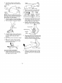
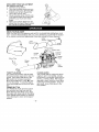
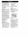
Instruction
Manual
(RRFTSMR
25cc/1.5 cu.in. 2-Cycle
200 MPH/400 CFM
GASOLINE
POWERED
BLOWER/VAC
Model No.
358.794550
•
Safety
WARNING:
Read and follow all Safety Rules and Operating
Instructions before first use of this product.
For answers to your questions about this product:
Call 7 am-7 pm, Mon.-Sat., or 10 am-7 pm, Sun.
1-800-235-5878
Sears,
530086582
Roebuck
10/1/01
and Co., Hoffman
_Hoors Hsted are Centre, Time)
Estates,
tL 60179
U.S.A.
Warranty Statement
Safety Rules
Assembly
Operation
Maintenance
Service & Adjustments
FULL TWO YEAR WARRANTY
2
2
4
6
9
11
Storage
Troubleshooting
Table
Emissions Statement
Parts List
Spanish
Parts and Ordering
ON CRAFTSMAN
12
13
13
15
18
Back
® GAS BLOWER
For two (2) years from date of purchase, when this Gas Blower is maintained,
Iubricated, and tuned up according to the instructions in the instruction manual,
Sears witi repair, free of charge, any defects in material or workmanship.
This warranty excludes blower tubes, spark plug, and air cleaner, which are expendable parts and become worn during normal use.
If this blower is used for commercial purposes, this warranty applies for 90 days from
the date of purchase. If this Blower is used for rental purposes, this warranty applies
for 30 days from the date of purchase. This warranty applies only while this product
is in use in the United States.
WARRANTY SERVICE IS AVAILABLE BY RETURNING THE BLOWER TO THE NEAREST
SEARS STORE OR SERVICE CENTER IN THE UNITED STATES.
This warranty gives you specific legal rights, and you may also have other rights
which vary from state to state.
Sears, Roebuck and Co., D/817WA, Hoffman Estates, IL 60179
,I_WAEINING:
Failure to follow all
Safety Rules and Precautions can result in serious injury.
KNOW YOUR UNIT
• Head your instruction manuaI carefully untit you completely understand
and can folIow aIi warnings and
safety rules before operating the unit.
• Restrict unit to users who understand and wilt follow all warnings and
safety rules in this manual.
,_ WARNING:
Inspect area before
starting unit. Remove all debris and
hard objects such as rocks, glass,
wire, etc. that can ricochet, be thrown,
or otherwise cause injury or damage
during operation.
Use your unit as a blower for:
• Sweeping debris or grass clippings
from driveways, sidewalks, patios, etc.
• Blowing grass clippings, straw, or
leaves into piles, around joints, or between bricks.
Use your unit as a vacuum for:
• Picking up dry material such as
leaves, grass, small twigs, and bits of
paper.
• For best results during vacuum use,
operate your unit at high speed.
• Move slowly back and forth over the
material as you vacuum. Avoid forcing the unit into a pile of debris as
this can ctog the unit.
• Keep the vacuum tube about an inch
above the ground for best resutts.
PLAN AHEAD
• Always wear eye protection when operating, servicing, or performing maintenance on unit. Wearing eye protection wilt help to prevent rocks or debris
from being blown or ricocheting into
eyes and face which can result in
blindness and/or serious injury. Eye
protection should be marked Z87.
• Always wear foot protection. Do not
go barefoot or wear sandals.
• Always wear respirator or face mask
when working with unit in dusty environments.
• Secure hair above shoulder length.
Secure or remove jewelry, loose
clothing, or clothing with loosely
hanging straps, ties, tassels, etc.
They can be caught in moving parts.
-2-
• Do not operate unit when you are
tired, ill, upset, or if you are under the
influence of alcohol, drugs, or medication.
• Keep children, bystanders, and animals away from work area a minimum of 30 feet (10 meters) when
starting or operating unit, Do not
point blower nozzle in the direction of
people or pets.
HANDLE FUEL WITH CAUTION, IT IS
HIGHLY FLAMMABLE
• Eliminate all sources of sparks or
flame (including smoking, open
flames, or work that can cause
sparks) in the areas where fuet is
mixed, poured, or stored.
• Mix and pour _el in an outdoor area;
store fuel in a cooI, dry, welt ventilated
place; use an approved, marked container for all fuel purposes.
• Do not smoke while handling fuel or
while operating the unit.
• Make sure the unit is properIy assembIed and in good operating condition.
• Do not fill fuel tank while engine is
running.
• Avoid spilling fuel or oil. Wipe up fuel
spills before starting engine.
• Move at least t0 feet (3 meters)
away from fuet and fueling site before starting engine.
• Always store gasoline in a container
approved for flammabIe liquids,
OPERATE YOUR UNIT SAFELY
_ItWARNING:
Stop the engine before opening the vacuum inlet door.
The engine must be stopped and the
impeller blades no longer turning to
avoid serious injury from the rotating
blades.
• Inspect unit before each use for
worn, loose, missing, or damaged
parts. Do not use until unit is in
proper working order.
• Keep outside surfaces free from oil
and fuel.
• Never start or run engine inside a
closed room, building or other unventilated area. Breathing exhaust
fumes can kitt.
• To avoid static electricity shock, do
not wear rubber gloves or any other
insulated gloves while operating unit.
• Do not set unit on any surface except a clean, hard area while engine
is running. Debris such as gravel,
sand, dust, grass, etc. could be
-3-
•
•
•
•
•
•
•
•
•
picked up by the air intake and
thrown out through discharge opening, damaging unit, property, or causing serious injury to bystanders or
operator.
Avoid dangerous environments.
Do
not use in unventilated areas or
where explosive vapors or carbon
monoxide build up could be present.
Do not overreach or use from unstable surfaces such as ladders, trees,
steep slopes, rooftops, etc. Keep firm
footing and balance at all times.
Never place objects inside the
blower tubes; always direct the blowing debris away from people, animals, glass, and solid objects such
as trees, automobiles, walls, etc. The
force of air can cause rocks, dirt, or
sticks to be thrown or to ricochet
which can hurt people or animals,
break glass, or cause other damage.
Never run unit without the proper
equipment attached. When using
your unit as a blower, always install
blower tubes, When using the optional vacuum kit, always install vacuum tubes and vacuum bag assembly. Make sure vacuum bag assembly is completely zipped.
Check air intake opening, blower
tubes, and vacuum tubes frequently,
always with engine stopped and
spark plug disconnected.
Keep vents
and discharge tubes free of debris
which can accumulate and restrict
proper air flow.
Never place any object in air intake
opening as this could restrict proper air
flow and cause damage to the unit.
Never use for spreading chemicals,
fertilizers, or other substances which
may contain toxic materials.
To avoid spreading fire, do not use
near leaf or brush fires, fireplaces,
barbecue pits, ashtrays, etc.
Use only for jobs explained in this
manual.
MAINTAIN YOUR UNIT PROPERLY
• Have all maintenance other than the
recommended procedures described
in the instruction manual performed
by a Sears Service Center.
• Disconnect spark plug before performing maintenance except for carburetor adjustments.
• Use only recommended
Craftsman_
replacement parts; use of any other
parts may void your warranty and
cause damage to your unit.
• Empty fuet tank before storing the
unit. Use up fuel left in carburetor by
starting engine and Ietting it run untit
it stops.
• Do not use any accessory or attachment other than those recommended
by manufacturer for use with your unit.
• Do not store the unit or fuel in a
closed area where fuet vapors can
reach sparks or an open flame from
hot water heaters, electric motors or
switches, furnaces, etc.
• Store in a dry area out of reach of
children.
SAFETY NOTICE: Exposure to vibrations through prolonged use of gasoline
powered hand tools could cause btood
vessel or nerve damage in the fingers,
hands, and joints of people prone to circulation disorders or abnormat swelling.
Prolonged use in cold weather has been
Iinked to biood vesset damage in otherwise healthy people. If symptoms occur
such as numbness, pain, toss of
strength, change in skin color or texture,
or loss of feeling in the fingers, hands, or
joints, discontinue the use of this tool
and seek medical attention. An
antivibration system does not guarantee
the avoidance of these problems. Users
who operate power tools on a continual
and regular basis must monitor closely
their physical condition and the condition
of this toot.
SPECIAL NOTICE: This unit is equipped with a temperature limiting muffler
and spark arresting screen which
meets the requirements of California
Codes 4442 and 4443. All U.S. forest
land and the states of California, Idaho. Maine, Minnesota. New Jersey.
Oregon, and Washington require by
law that many internal combustion engines be equipped with a spark arresting screen. Ifyou operate in a locale
where such regulations exist, you are
legally responsible for maintaining the
operating condition of these parts.
Failure to do so is a violation of the
law. Refer to the MAINTENANCE section for information on maintenance of
the muffler and spark arresting screen.
BLOWER
CARTON
CONTENTS
Check carton contents against the following list.
Model 358.794550
Blower
Blower tube
Elbow tube
ASSEMBLY
BLOWER TUBE ASSEMBLY
If you have already assembled your
unit for use as a vacuum, remove the
vacuum tubes and collection bag.
1. Align the rib on the btower tube
with the groove in the blower outlet;
slide the tube into place.
NOTE: Tube clamp must be loose
enough to allow blower tube to be insetted in blower outlet. Loosen tube
Vacuum bag
Upper vacuum tube
Lower vacuum tube
Gasoline container
2-Cycle Engine Oil
NOTE: tt is normal for the fuel filter to
clamp by turning knob counterclockwise.
rattle in the empty fuel tank.
ASSEMBLY
J_I'WARNING:
Stop engine and be
sure the impeller blades have stopped
turning before opening the vacuum inlet door or attempting to insert or remove the vacuum tubes. The rotating
blades can cause serious injury.
2.
3.
_ItWARNING:
unit assembled,
sure your unit is
and all fasteners
tf you receive your
repeat atl steps to enproperly assembIed
are secure.
A standard screwdriver
for assembly.
Tighten the tube ctamp by turning
the knob clockwise.
To remove the tube, turn the knob
to loosen clamp; remove tube.
VACUUM
ASSEMBLY
VACUUM BAG ASSEMBLY
1, Open the zipper on the vacuum
bag and insert the elbow tube.
is required
-4-
2.
Push the small end of the elbow
tube through the small opening in
the bag.
Elbow
Tube
Small
Upper
Vacuum Tube
Jacuum Tube
2.
Insert a screwdriver into the latch
area oTi the ,,/aCLtUl'flinter oo_/er.
Latch
_
Blower
Opening
Area
Rib
NOTE: Make sure edge of the smaIl
opening is flush against the flared area
of the etbow tube, and the rib on the
elbow tube is on the bottom.
3. Close the zipper on the bag. Make
sure the zipper is closed completely.
4. Remove blower tube from engine.
Outlet
_
3.
4.
Inlet Cover
Gently titt the handle of the screwdriver toward the back of the unit
while pulling up on the vacuum inlet cover with 'your other hand.
Hold the vacuum inlet cover open
until upper vacuum tube is stalled.
Vacuum Inlet
v_
Retaining Post
-_
'_
Inlet
5.
6.
7.
Insert the elbow tube into the btower outlet, Make sure elbow tube is
aligned with the blower outlet
groove.
Turn clamp knob clockwise to tighteR.
Secure the ends of the shoulder
strap by routing the strap through
the buckle as shown.
5.
Place the hooks on the vacuum tube
on the retaining posts; pivot tube into
position. Secure vacuum tube by
turning the knob clockwise until tight.
Hooks
6.
VACUUM TUBE ASSEMBLY
1. Align the lower vacuum tube as
shown. Push lower vacuum tube
into upper vacuum tube.
-5-
When converting back to the blower feature, make sure latch on the
vacuum inlet cover is securely fastened.
SHOULDER STRAP ADJUSTMENT
(for vacuum u_e only)
1. HoId the unit as shown.
2. Pass the shoulder strap over your
head and onto your right shoulder.
3. Extend your left arm toward the
rear of the vacuum bag.
4. Adjust shoulder strap until the vacuum bag/shoulder
strap seam lies
between your thumb and index
finger.
5. Make sure air flows freely from the
elbow tube into bag. tf bag is kinked,
the unit wilt not operate properly.
KNOW YOUR SLOWER
READ THIS INSTRUCTION MANUAL AND SAFETY RULES BEFORE OPERATING YOUR
UNIT Compare the illustrations with your unit to familiarize yourself with the location
of the various controls and adjustments. Save this manual for future reference.
Upper
Lower
Vacuum Tube
Primer Button
Choke Lever
Throttle
Lever_
Starter
Rope
Elbow Tube
\
Fuel Mix
Blower
Tube
\
Rear
HandIe
THROTTLE
LEVER
The THROqqLE LEVER is used to select
the desired engine speed and to stop the
engine. Move the throttle lever to the
position for full speed operation.
Move the throttle lever to the _
position for idle speed. To stop the engine,
move the throttle lever to the STOP position.
PRIMER BUTTON
The PRIMER BLrTTON removes air from
the carburetor and fuel tines and f_tls
them with fuel. This allows you to start
the engine with fewer pulls on the starter
rope. Activate primer button by pressing
it and allowing it to return to its original
position.
CHOKE LEVER
The CHOKE helps to supply fuel to the
engine to aid in cold starting, Activate
the choke by moving the choke lever to
the FULL CHOKE position. After engine
attempts to start, move the choke lever
to the HALF CHOKE position, Once engine starts, move choke lever to the
RUN position.
-6-
OPERATING TIPS
• While vacuuming or blowing debris,
hotd the unit with the muffler side facing away from your body and cIothes
(see OPERATING POSITION).
• To reduce the risk of hearing toss
associated with sound level(s), hearing protection is required.
• To reduce the risk of injury associated
with contacting rotating parts, stop the
engine before installing or removing
attachments. Do not operate without
guard(s) in place.
• Operate power equipment only at reasonable hours-not early in the morning or late at night when people might
be disturbed. Comply with times listed
in local ordinances. UsuaI recommendations are 9:00 a.m. to 5:00 p.m.,
Monday though Saturday.
• To reduce noise levels, limit the number of pieces of equipment used at
any one time.
• To reduce noise levels, operate power blowers at the lowest possible
throttle speed to do the job.
• Use rakes and brooms to toosen
debris before blowing.
• In dusty conditions, slightly dampen
surfaces or use a mister attachment
when water is avaiIable.
• Conserve water by using power blowers instead of hoses for many lawn
and garden applications, including
areas such as gutters, screens, patios,
grills, porches, and gardens.
• Watch out for children, pets, open
windows, or freshly washed cars.
Blow debris away safely.
• Use the full blower nozzle extension
so the air stream can work close to
the ground.
• After using blowers and other equipment, CLEAN UP! Dispose of debris
in trash receptacles.
OPERATING
POSITION
BEFORE
STARTING
A0&WARNING:
ENGINE
Be sure to read the
fuel information in the safety ruIes
before you begin, tf you do not
understand the safety ruIes, do not
attempt to fuet your unit. Call
1-800-235-5878.
FUELING
ENGINE
_WARNING:
Remove fuel cap
slowly when refueling.
This engine is certified to operate on
unleaded gasoline. Before operation,
gasoline must be mixed with a good
quality synthetic 2-cycle air-cooled engine oil. We recommend Craftsman
brand synthetic oil Mix gasoline and
oil at a ratio of 40:1 (A 40:1 ratio is obtained by mixing 3.2 ounces of oil with
1 gallon of unleaded gasoline). DO
NOT USE automotive oil or boat oil.
These oils wilt cause engine damage.
When mixing fuel, follow instructions
printed on container.
Once oil is added to gasoline, shake
container momentarily to assure that
the fuet is thoroughly mixed. Always
read and follow the safety rules relating to fuel before fueling your unit.
IMPORTANT
Experience indicates that alcohol
blended fuels (catted gasohot or using
ethanol or methanol) can attract moisture which leads to separation and
formation of acids during storage.
Acidic gas can damage the fuel system of an engine while in storage.
To avoid engine problems, empty the
fuel system before storage for 30 days
or longer. Drain the gas tank, start the
engine and tet it run until the fuel lines
and carburetor are empty. Use fresh
fuel next season.
Never use engine or carburetor cleaner products in the fuel tank or permanent damage may occur.
Fuel stabilizer is an acceptabIe alternative in minimizing the formation of
fuel gum deposits during storage.
Craftsman brand oit is already blended
with fuel stabilizer. See the STORAGE
section for additional information.
STOPPING
Blower
YOUR ENGINE
• To stop the engine, move the throttle
tever to the STOP position.
Vacuum
-7-
STARTING
THE ENGINE
_II'WARNING:
You MUST make sure
the tubes are secure before using the
unit.
• Fuel engine, Move at least 10 feet (3
meters) away from the fueling site,
• Hold the unit in the starting position
as shown. Make sure the biower end
is directed away from people, animals, glass, and solid objects.
STARTING POSITION
Blower
Vacuum
_ll WARNING:
When starting engine,
hold the unit as illustrated. Do not set
unit on any surface except a clean, hard
area when starting engine or while engine is running. Debris such as gravel,
sand, dust, grass, etc. could be picked
up by the air intake and thrown out
through the discharge opening, damaging the unit or property, or causing serious injury to bystanders or the operator.
STARTING A COLD ENGINE (or a
warm engine aRer running out of
fuel)
1. Move the throttle lever to the
position.
2. Move the choke lever to the FULL
CHOKE position.
3. Slowly press the primer button 8
times.
ThrottIe Lever
Primer Button
Choke Lever
4.
Putt starter handle sharply until the
engine attempts to run, but no
more than 5 pulls (below 3O°F, 8
pulls).
-8-
NOTE: If the engine attempts to start
before the 5th putt, go to the next step
immediately.
5. Move choke lever to HALF CHOKE.
6, Putt the starter handle sharply until
the engine runs, but no more than
5 pulls (beIow 30 F, 10 pulls),
7. After a 5 second warm-up, move
the choke lever to the RUN position.
8. Attow the unit to run for 30 more
seconds at RUN before moving the
throttle lever to the _
position.
tf the engine has not started after 5
pulls (at HALF CHOKE), repeat the
STARTING A COLD ENGINE procedure.
tf the engine still does not start, proceed to STARTING A FLOODED ENGINE.
9. To stop the engine, move the
throttle lever to the STOP position.
STARTING A WARM ENGINE
1. Move the throttte lever to the 4_
position.
2. Pull the starter handle sharply until
the engine starts, but no more than
5 pulls.
NOTE: tf the engine has not started,
pull starter handie sharply for 5 more
pulls. If engine stiIt does not run, it is
probably flooded. Proceed to STARTING A FLOODED ENGINE.
3.
To stop the engine, move the
throttle lever to the STOP position.
STARTING A FLOODED ENGINE
Flooded engines can be started by placing the choke lever in the RUN position.
Move throttle lever to the fast position
z_ ; then, pull rope until engine starts.
After engine starts, move the throttle lever to the slow position _
to aliow engine to idIe.
Starting could require pulling the starter
rope many times depending on how
badly the unit is flooded. If the unit still
doesn't start, refer to the
TROUBLESHOOTING TABLE or caII
1-800-235-5878.
CUSTOMER
RESPONSIBILITIES
CARE & MAINTENANCE
TASK
WHEN TO PERFORM
Check for loose fasteners
and parts
Before each use
Check for damaged
Before each use
or worn parts
After each use
Inspect and clean unit and tabels
Clean air filter
Inspect muffler and spark arresting
Replace spark plug
Every 5 hours of operation
screen
Replace fuel filter
Check muffler bolts
Yearly
Yearly
z_ _____._=
,_IIWARNING:
Avoid touching muffler untess engine and muffler are cold,
A hot muffler can cause serious burns,
A_iI'WARNING:
Every 50 hours of operation
"Yearly
Stop engine and be
sure the impeller blades have stopped
turning before opening the vacuum inIet door or attempting to insert or remove the vacuum or blower tubes.
The rotating blades can cause serious
injury, Always disconnect the spark
plug before performing maintenance or
accessing movable parts.
INSPECT AND CLEAN UNIT
AND LABELS
• After each use, inspect complete unit
for loose or damaged parts, Clean
the unit using a damp cloth with a
mitd detergent.
• Wipe off unit with a clean dry cloth.
CLEAN AIR FILTER
G EN ERAL R ECOMMENDATIONS
The warranty on this unit does not cover items that have been subjected to
operator abuse or negligence. To receive futt value from the warranty, the
operator must maintain unit as instructed in this manual. Various adjustments
witt need to be made periodically to
properly maintain your unit,
CHECK FOR LOOSE
FASTENERS AND PARTS
• Spark PIug Boot
• Air Filter
• Housing Screws
CHECK FOR DAMAGED
OR
WORN PARTS
Contact Sears Service Center for replacement of damaged or worn parts.
• Throttle Lever - Ensure throtge tever
functions propedy by moving the
throttle tever to the STOP position.
Make sure engine stops; then restart
engine and continue.
•FueI Tank - Do not use unit if fuel tank
shows signs of damage or leaks.
• Vacuum Bag - Do not use vacuum
bag if it is torn or damaged,
-9-
A dirty air filter decreases engine performance and increases fuel consumption and harmful emissions. Always
ctean after every 5 hours of operation,
Cleaning the air filter:
1. Clean the cover and the area
around it to keep debris from failing
into the carburetor chamber when
the cover is removed.
2. Remove parts as illustrated.
NOTE: Do not clean filter in gasotine
or other flammable solvent. Doing so
can create a fire hazard or produce
harmful evaporative emissions.
3, Wash the fitter in soap and water.
4. Allow filter to dry.
5, Apply a few drops of oil to the filter;
squeeze filter to distribute oil,
6, Replace parts.
REPLACE SPARK PLUG
Repiace spark pIug each year to ensure the engine starts easier and runs
better. Set spark plug gap at 0.025
inch. Ignition timing is fixed, nonadjustable.
1. Twist, then putt off spark plug boot.
2. Remove spark plug from cylinder
and discard.
3. Replace with Champion CJ-6Y
spark plug and tighten securely
with a 3/4 inch socket wrench.
4. Reinstall the spark plug boot.
REPLACE FUEL FILTER
To replace fuet fitter, drain unit by running it dry of fuel, then remove fuel
cap/retainer assembly from tank. Pull
filter from tank and remove it from the
fuel line. Install new fuel filter on fueI
tine; reinstall parts.
1.
Remove two screws from muffler
cover. Remove muffler cover.
2. Loosen and remove the 2 cap
screws from the muffler mounting
screw holes.
3. Tighten the 2 mounting screws securely.
4. Reinstall and tighten the 2 cap
screws securely.
5. Reinstall muffler cover and 2
screws. Tighten securely.
INSPECT MUFFLER AND SPARK
ARRESTING SCREEN
_ILWARNING:
The muffler on this
product contains chemicals known to
the State of California to cause cancer.
As the unit is used, carbon deposits
build up on the muffler and spark arresting screen, and must be removed
to avoid creating a fire hazard or affecting engine performance.
TOP VIEW OF MUFFLER
Exhaust
\
\
'l
/
Fuel Filter
/,/
CHECK MUFFLER MOUNTING
SCREWS
Once each year, ensure muffIer
mounting screws are secure and tightened properly to prevent damage.
Screw
Holes
Replace the spark arresting screen every 50 hours of operation or if any
damage or breaks in the screen are
noted.
NOTE: Do not attempt to clean the
spark arresting screen.
1. Remove two screws from muffler
cover. Remove muffler cover.
2. Loosen and remove both screws
from the exhaust diverten
3. Remove the exhaust diverter and
spark arresting screen.
4. install new spark arresting screen.
5. Reinstall exhaust diverter and both
6.
NOTE: The muffler mounting screws
are located behind the cap screws.
The cap screws must be removed to
access the mounting screws.
screws. Tighten screws securely.
Reinstall muffler cover and 2
screws. Tighten securely.
NOTE: If any part of the muffler is
cracked, broken or damaged, we recommend that the muffler be replaced.
-10-
We recommend att service and adjustments not listed in this manual be performed by your Sears Service Center,
CARBURETOR
ADJUSTMENT
Carburetor adjustment is critical and if
done improperly can permanently
damage the engine as welt as the carburetor, if you require further assistance or are unsure about performing
this procedure, calt our customer assistance help line at 1-800-235-5878.
Old fuel, a dirty air filter, a dirty fuel filter, or flooding may give the impression of an improperly adjusted carburetor. Check these conditions before
adjusting the carburetor.
The carburetor has been carefully set
at the factory, Adjustments may be
necessary if you notice any of the following conditions:
• Engine wiit not idle. See LOW SPEED
MIXTURE ADJUSTMENT (L) under adjusting procedure,
• Engine dies or hesitates instead of accelerating. See ACCELERATION CHECK
under adjusting procedure,
• Loss of power. See MIXTURE ADJUSTMENT (L or H) under adjusting procedure.
There are two adjustment screws on
the carburetor. The low speed adjustment screw is marked with the letter L,
and the high speed adjustment screw
is marked with the letter H. The throttle
lever is used to control engine speed.
The throttle lever can be placed in one
offour positions: STOP, iDLE or _,
FULLTHROTFLE or _, and one intermittent position.
Primer Button
Throttle Lever
,/.4 _ _-_Adjustment
Adjustment 'U'
ADJUSTING PROCEDURE
CAUTION:
Do not force plastic limiter
caps on screws beyond the built-in
stops or damage witi occur.
Initial Setting8
1. Turn both mixture screws (L and H)
counterclockwise until they stop.
2. Start engine, let it run for 3 minutes,
then proceed to adjust screws according to the instructions below. If
engine performance at initiat settings
is acceptable, no further adjustments
are necessary, tf engine does not
start, refer to TROUBLESHOOTING
TABLE. If still unable to remedy situation, cali 1-800-235-5878.
Low Speed Mixture Adjustment
- L
1. Allow the engine to idle.
2. Turn Iow speed mixture screw (L)
slowly clockwise until the speed begins to drop,
3, Turn the low speed mixture screw
(L) counterclockwise until the speed
increases and then starts to drop
again.
4. Set the low speed mixture screw (L)
at the midpoint between the two
positions.
High Speed Mixture Adjustment
- H
CAUTION:
Adjust the mixture screw
1/16 of a turn at a time. A 1/16 turn is
about the width of the slot in the top of
the screw.
1. Run engine at futl throttle.
2. Turn the high speed mixture screw
(H) counterclockwise until it stops.
3. Turn the high speed mixture screw
(H) 1/18 of a turn clockwise at a time
untit the engine runs smoothly.After
completing adjustments, check for
acceleration. Reset if necessary.
Acceleration
Check
If engine dies or hesitates instead of
accelerating, turn the Iow speed mixture screw (L) counterclockwise
until
you have smooth acceleration.
"H"
-11
-
WARNING:
Perform the following
steps after each use:
• Allow engine to cool, and secure the
unit before storing or transporting.
• Store unit and fuel in a welt ventilated area where fuel vapors cannot
reach sparks or open flames from
water heaters, electric motors or
switches, furnaces, etc.
• Store unit with all guards in place.
Position unit so that any sharp object
cannot accidentally cause injury.
• Store unit and fuel welt out of the
reach of children.
SEASONAL
STORAGE
Prepare unit for storage at end of season or if it wilt not be used for 30 days
or more.
If your unit is to be stored for a period
of time:
• Clean the entire unit before lengthy
storage.
• Store in a clean dry area.
• Lightly oil external metal surfaces.
FUEL SYSTEM
Under FUELING ENGINE in the OPERATION section of this manuaI, see message tabeIed IMPORTANT
regarding
the use of gasohot in your engine.
Fuel stabilizer is an acceptable alternative in minimizing the formation of fuel
-12-
gum deposits during storage. Add stabilizer to gasoline in fuel tank or fuel storage container. Fotlow the mix instructions found on stabilizer container. Run
engine at least 5 minutes after adding
stabilizer.
Craftsman 40:1,2-cycle
engine oit (air
cooled) is already blended with fuel
stabilizer, tf you do not use this Sears
oil, you can add a fuel stabilizer to your
fuel tank.
ENGINE
• Remove spark ptug and pour 1 teaspoon of 40:1, 2-cycle engine oil (air
cooled) through the spark plug opening. Slowly pull the starter rope 8 to
10 times to distribute oil.
• Replace spark plug with new one of
recommended type and heat range.
• Clean air filter.
• Check entire unit for loose screws,
nuts, and bolts. Replace any damaged, broken, or worn parts,
• At the beginning of the next season,
use only fresh fuel having the proper
gasoline to oil ratio.
OTHER
• Do not store gasoline from one season to another.
• Replace your gasoline can if it starts
to rust.
TROUBLESHOOTING
TABLE
_, WARNING:
Always stop unit and disconnect spark plug before performing any of the recommended remedies below other than remedies that require operation of the unit.
TROUBLE
Engine will not
start.
CAUSE
REMEDY
1. Engine flooded.
2. Fuel tank empty.
3. Spark p}ug not tiring.
g. Fuel not reaching
carburetor.
5. Compression
Engine will not
idle properly
2. Carburetor
adjustment
3. Crankshaft
4. Compression
Engine wil_ not
accelerate,
lacks power, or
dies under a
load.
low
1. Fuel not reaching
carburetor.
requires
seals worn
low
t. Air filter dirty.
2 Fuel not reaching
carburetor.
3. Spark plug fouled
4. Spark arresting screen
clogged.
5 Carburetor requires
adjustment.
6 Carbon build up.
7 Compression
low.
Engine smokes
excessively.
t. Choke partially on.
2. Fue_ mixture incorrect.
3. Air filter dirty.
4. Carburetor requires
adjustment.
Engine
runs hot.
t
Fuet mixture
incorrect.
2. Spark plug incorrect.
3 Carburetor requires
adjustment.
4 Carbon build up
t. See "Starting a Flooded Engine"
in Operation section.
2. Fill tank with correct fuel mixture.
3. hstafl new spark plug.
4. Check for dirty fuel filter; repIace
Check for kinked or split fuel line;
repair or replace.
5. Contact your Sears Service Center
1. Check for dirty fuel filter; replace.
Check for kinked or split fuel Iine;
repair or replace.
2. See "Carburetor Adjustment" in
Service and Adjustments
section
3. Contact your Sears Service Center.
4. Contact your Sears Service Center.
1. Clean or replace air filter.
2 Check for dirty fuel filter; replace.
Check for kinked or split fuel line;
repair or replace.
3. Clean or replace spark plug
and re-gap.
4. Replace screen.
5 See "Carburetor Adjustment"
in
Service and Adjustments section.
6 Contact your Sears Service Center
7 Contact your Sears Service Center.
t Adjust choke.
2 Empty fuel tank and refill with
correct fuel mixture.
3 Clean or replace air filter
4 See "Carburetor Adjustment" in
Service and Adjustments
section.
t. See "Fueling
section.
Engine"
in Operation
2. Replace with correct spark plug.
3. See "Carburetor Adjustment"
in
Service and Adjustments section.
4. Contact your Sears Service Center
YOUR WARRANTY RIGHTS AND OBLIGATIONS: The U.S. Environmental
Protection Agency/California Air Resources Board and Sears, Roebuck and
Co., U.S.A., are pleased to explain the
emissions control system warranty on
your year 2000-2003 small off-road engine. In California, all new small off-road
engines must be designed, built, and
equipped to meet the State's stringent
anti-smog standards. Sears must warrant the emission control system on your
-13-
small off-road engine for the periods of
time listed below provided there has
been no abuse, neglect, or improper
maintenance of your smaII off-road engine engine. Your emission controI system includes parts such as the carburetor and the ignition system. Where a
warrantable condition exists, Sears wilt
repair your small off-road engine engine
at no cost to you. Expenses covered under warranty include diagnosis, parts
and labor. MANUFACTURER'S
WAR-
RANTY COVERAGE: If any emissions
related part on your engine (as listed under Emissions Control Warranty Parts
List) is defective or a defect in the materials or workmanship of the engine
causes the faiture of such an emission
related part, the part will be repaired or
reptaced by Sears. OWNER'S WARRANTY RESPONSIBILITIES:
As the
small off-road engine engine owner, you
are responsible for the performance of
the required maintenance listed in your
instruction manual Sears recommends
that you retain all receipts covering
maintenance on your small off-road engine, but Sears cannot deny warranty
solely for the lack of receipts or for your
failure to ensure the performance of aII
scheduled maintenance, As the small
off-road engine engine owner, you
should be aware that Sears may deny
you warranty coverage if your small offroad engine engine or a part of it has
failed due to abuse, neglect, improper
maintenance, unapproved modifications,
or the use of parts not made or approved by the original equipment
manufacturer. You are responsible for
presenting your small off-road engine to
a Sears authorized repair center as
soon as a problem exists. Warranty repairs should be completed in a reasonabte amount of time, not to exceed 30
days, If you have any questions regarding your warranty rights and responsibilities, you shouId contact your nearest
authorized service center or calI Sears
at 1-800-469-4663. WARRANTY COMMENCEMENT DATE: The warranty period begins on the date the small offroad engine is purchased. LENGTH OF
COVERAGE: This warranty shall be for
a period of two years from the initial date
of purchase. WHAT IS COVERED: REPAIR OR REPLACEMENT OF PARTS.
Repair or replacement of any warranted
part will be performed at no charge to
the owner at an approved Sears Service
Center. If you have any questions regarding your warranty rights and responsibilities, you shouId contact your nearest authorized service center or calf
Sears at 1-800-469-4683. WARRANTY
not scheduled for replacement as required maintenance, or which is scheduled only for reguIar inspection to the
effect of "repair or replace as necessary"
shall be warranted for 2 years, Any warranted part which is scheduled for replacement as required maintenance
shall be warranted for the period of time
up to the first scheduled replacement
point for that part. DIAGNOSIS: The
owner shail not be charged for diagnostic labor which leads to the determination that a warranted part is defective if
the diagnostic work is performed at an
approved Sears Service Center. CONSEQUENTIAL DAMAGES: Sears may
be liable for damages to other engine
components caused by the failure of a
warranted part still under warranty.
WHAT IS NOT COVERED: Atl failures
caused by abuse, negtect, or improper
maintenance are not covered. ADD-ON
OR MODIFIED PARTS: The use of
add-on or modified parts can be
grounds for disallowing a warranty ctaim.
Sears is not liabie to cover faitures of
warranted parts caused by the use of
add-on or modified parts. HOW TO
FILE A CLAIM: If you have any questions regarding your warranty rights and
responsibilities, you shouid contact your
nearest authorized service center or call
Sears at 1-800-469-4663. WHERE TO
GET WARRANTY SERVICE: Warranty
services or repairs shall be provided at
all Sears Service Centers. Call
1-800-489-4883.
MAINTENANCE,
REPLACEMENT
AND REPAIR OF EMISSION RELATED PARTS: Any Sears approved
replacement part used in the performance of any warranty maintenance or
repair on emission related parts wiII be
provided without charge to the owner if
the part is under warranty. EMISSION
CONTROL WARRANTY PARTS LIST:
Carburetor, Ignition System: Spark Plug
(covered up to maintenance schedule),
Ignition Module, Muffler including catalyst. MAINTENANCE
STATEMENT:
The owner is responsible for the performance of all required maintenance as
defined in the instruction manual
PERIOD: Any warranted part which is
This engine is certified to be emissions
[]
Moderate
[]
Intermediate
[]
Extended
compliant
(50 hours)
(125 hours)
(300 hours)
-14-
for the following
use: