1
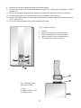
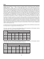
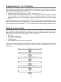
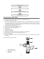
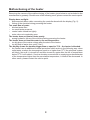
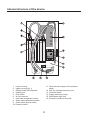
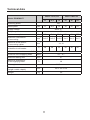
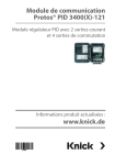
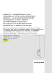
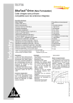
INSTALLATION
AND OPERATION
MANUAL
Flow water heaters type
POW-LCD MULTI
Before using the heater, please read the instructions carefully. In the future
it will benefit by its failure-free operation for a long time.
Flow water heaters series POW-LCD MULTI are intended for heating tap water. They can supply hot water to several water outlets located in different rooms. These heaters are equipped
with heating coils which are directly washed by water. Such direct process of heating prevents
scale formation and ensures high efficiency and speed of heating water. The microprocessor
system analyses the temperature of inlet and outlet water, the set temperature, and water
consumption of the user. Based on the collected data, it increases or decreases the heating
power in such a way that the water temperature at the outlet corresponded to the temperature
set by the user. Such control of the heater operation ensures the comfort of use and energy
saving. Additionally, the heater is equipped with the possibility of choosing rated power. It is
equipped with air lock sensors which limit, to the minimum, the possibility of damage of the
heating elements due to air locking of the water distribution system, as well as the system
adjusting the temperature drop caused by the drop of supply voltage.
Heaters can additionally heat water that was pre-heated, e.g. with the use of the solar system
which at the heater inlet cannot exceed 60OC.
• The device cannot be installed in rooms in which the temperature may
fall below 0OC and in which there is the risk of explosion.
• This equipment is not intended to be used by persons (including children) of lower physical, sensory or mental capability, unless they operate
it under supervision.
• Attention should be paid to children not playing with the equipment.
Installation instructions
The installation and start-up of the POW-LCD MULTI heater should be done by a person
qualified in accordance with the guidelines contained in the Manual. All installation works
should be carried out with disconnected power and water supplies. The heater electrical installation should be conducted in accordance with the binding regulations. The device should be
permanently connected to electrical wiring with ground terminal. The electrical wiring should
be equipped with residual current circuit breaker protecting against electric shock and with a
switch ensuring the disconnection of the device from the power source, in which the distance
between the contacts should be not less than 3 mm.
1. To the place in which the heater is to be installed lead electrical wiring and water distribution system, using for that the mounting template.
2. Drill holes and mount expansion plugs.
3. Install the control valve with a filter on cold water supply (Fig. 3).
4. Unscrew the fastening screw which holds the housing of the heater located at the bottom
of it (Fig. 1), take off the cover and disconnect the ribbon cable by taking the plug out of
the socket marked “LCD” (Fig. 2).
5. Select rated power by transferring the link to a proper place on a contact marked MOC
according to the description on the sticker. 6. Screw the heater to the wall with the use of fastening screws, having earlier run the power
cable through the hole.
7. Check the starting of pressure switch.
2
8. Remove the securing blanking plugs from water pipes.
9. Connect the heater to the water distribution system (Fig. 5 service line marked 14, outlet
marked 15)
10. Switch on the water supplying the heater and check the tightness of the connections.
11. Connect the heater to the electrical wiring in accordance with Figure 4.
12. Connect the ribbon cable by inserting the plug with the proper side to the socked marked
“LCD”, see (Fig. 2).
13. Put on the housing and screw it with a fastening screw.
Fig. 1 Heater housing
1. 2. 3. 4. 5. Fig. 2 Display board
with ribbon cable
1. Plug
2. Socket marked “LCD”
3. Display board
3
Display
Button increasing the set temperature
Button decreasing the set temperature
Memory buttons of the set temperature
The screw fastening the housing
Fig. 3.
Fig. 4 Diagram of electrical wiring
Water heater
Starting
In order to remove air from the water distribution system and the heater, before turning the
power on, open the hot water valve for approx. 20 seconds in order to remove air bubbles
from the system. Then, turn the power on. Open the hot water valve waiting till the device has
achieved full operational readiness (approx. 5 seconds) beginning the process of heating – in
the lower part of display lines will be shown indicating (in percent) the heating power of the
heater. Close the hot water valve. The heating process is automatically turned off – the lines
previously indicating the heating power will disappear from the display.
4
Use
Setting the temperature of water is done by pressing one of the buttons located under the
display marked “–” and “+ ” (Fig. 1) in the range from 30OC to 60OC accurate every 0.5OC.
Detecting the flow greater than 2.7 l/min by the heater system will result in switching off the
device. The lines of the barograph (lower part of the display) show the power with the heater
heats the water. The appearance of one line means the heater is heating with the power not
smaller than 10% and not greater than 20% of the rated power. The appearance of five lines
means the heater is heating with the power not smaller than 50% and not greater than 60% of
the rated power. The appearance of all ten lines means the heater is heating with full power.
The signalling by the heater that it is heating with full power is the information for the user to
decrease the consumption of water or decrease the set temperature because the power of
the device at a given moment is not small to heat up water to the desired temperature. After
each start or change of the set temperature, the heater measures temperature of outlet water
every 10 seconds. If two temperature measurements are the same it means the temperature
has stabilized and the electronic system can compare it with the set temperature. In case
when the obtained temperature is smaller from the set temperature due to the drop of the
mains voltage, the heater increases the power automatically, so that the water temperature
achieved the desired value.
In case when the inlet temperature exceeds 55OC, the heater will turn off till the moment when
the temperature of supply water will fall below 55OC.
Hot water capacity (in litres per minute) depending on the temperature of inlet water and the
selected power for heater POW-LCD MULTI 18/21/24
Water
temperature
at the inlet
Water temperature at the outlet
18 kW
5OC
7,4
8,7
9.9
5,8
6,7
7,7
10OC
8,6
10,1
11,6
6,5
7,6
8,7
15 C
10,4
12,1
13,9
7,4
8,7
9,9
O
40OC
21 kW
50OC
24 kW
18 kW
21 kW
24 kW
Hot water capacity (in litres per minute) depending on the temperature of inlet water and the
selected power for heater POW-LCD MULTI 11/13.5/15
Water
temperature
at the inlet
Water temperature at the outlet
11 kW
13,5 kW
15 kW
11 kW
13,5 kW
15 kW
5OC
4,5
5,5
6,2
3,5
4,3
4,8
10 C
5,3
6,5
7,2
3,9
4,8
5,4
15OC
6,3
7,8
8,7
4,5
5,5
6,2
O
40OC
50OC
5
Programming T1, T2, T3 buttons
The heater can save three values of temperatures selected by the user. To save, as well as
select temperatures the buttons marked T1, T2, T3 are used. In order to assign the temperature value to any of the buttons (T1, T2, T3):
1. Set the desired temperature on the display by pressing “–” or “ + ”
2. Hold down any of the selected buttons ( T1, T2, T3) for approx. 4 seconds till the moment
when the digits on the display will go out for a moment signalizing by that that the value
of the temperature set on the display has been assigned to the memory of the pressed
button.
After short pressing of any of the buttons (T1, T2, T3), the programmed temperature will be
displayed, and thereby the set temperature with which the heater is to heat the water. In order
to re-program any of the buttons (T1, T2, T3), follow the instructions given in points 1 and 2.
Display service mode
The simultaneous pressing of buttons marked “–” and “ + ” for about 1 second will make the
display shift from the basic mode (the information about the set temperature and power is
displayed) to the service mode enabling to show such data as:
– flow rate
– inlet water temperature
– outlet water temperature
– installed power
– staring additional sensors (air lock sensors)
In the service mode the display shows different data for approx. 3 separating them by shortly
displaying “0.0”. After displaying the last piece of data, the display automatically shifts to the
basic mode
Flow
0.0
Input water temperature
0.0
Output water temperature
0.0
6
0.0
Installed power
0.0
Installation of airlock sensors
Basic mode
Cleaning the water filter
In a situation when the filter has become fully or partially blocked:
1. Disconnect the power supply.
2. Unscrew the fastening screw located at the bottom of the housing (Fig. 1), then take off
the housing holding it at such a distance from the heater that the ribbon cable connecting
the display with the heater was not tightened, and then disconnect the cable by plugging
it out of the socket marked “LCD” (Fig. 2).
3. Close the control valve (marked 1).
4. Unscrew the control valve plug (marked 2).
5. Take out the mesh filter (marked 3).
6. Remove dirt.
7. Insert the mesh filter.
8. Screw the valve plug.
9. Open the control valve and check the tightness of connections.
10. Connect the ribbon cable of the display board (Fig. 2).
11. Close the housing.
12. Remove entrapped air from the heater, and then start it in accordance with chapter
“Starting”.
Fig. 4 Control valve with the filter
1. 2. 3. Control valve knob
(position: flow closed)
Valve plug
Mesh filter
7
Malfunctioning of the heater
Removing the causes of the malfunctioning of the heater given below is not included in the
manufacturer’s guaranty. Should none of the following occur, please contact the service point.
Display does not light:
– disconnected ribbon cable connecting the controller board with the display (Fig. 2).
– failure of the electrical wiring powering the heater.
Too small flow of water:
– blocked water filter.
– too small water pressure.
– control valve closed too tightly.
– main valve not completely open.
The heater does not heat or heats poorly:
– wrong hydraulic, failure of the electrical wiring powering the heater.
The heater does not heat the water to the set temperature:
– too big drop of the mains voltage after the start of the heater.
– too big flow of water (see: point “Use”).
The display shows the number bigger than or equal to 75.0 – the heater is blocked.
– the heater has an additional thermal protection which works in the following way: when
outlet water reaches the temperature equal to or higher than 75OC the electrical system
will block. Not until it is turned off and then turned on again after the fall of temperature
below 75OC it will unblock. If such a situation occurred due to supplying pre-heated water
of the temperature higher than the permissible temperature, it needs to be decreased. In
other cases, please contact the service point.
8
Internal structure of the device
1. Lower housing.
2. Upper housing (fig. 1)
3. Display board with keyboard.
4. Heating unit.
5. Flow switch.
6. Air lock sensors.
7. Inlet water temperature probe.
8. Outlet water temperature probe.
9. Outlet water thermal switch.
10. Pressure switch.
11. Terminals will be parts of the pressure
switch.
12. Hole for inserting the power cord.
13. Controller board.
14. Supply water pipe (cold)
15. Outlet water pipe (hot)
16. Protective conductor terminal.
9
Fig. 7 Schematic diagram of POW-LCD MULTI
1 – thermal switch
2 – display board and keyboard
3 – flow switch (turbine)
4 – inlet water temperature probe
5 – outlet water temperature probe
6, 7 – flow switch and air lock sensor
8 – heating unit
9 – heater controller
10 – pressure switch
PE – protective conductor terminal
E – electrode
G1, G2, G3 – heating elements
10
Technical data
MULTI 11/13,5/15
Heater POW-MULTI
11
13,5
11
13,5
Switching power
Rated power
Power consumption
15
18
21
24
18
21
24
Yes
kW
Supply voltage
Frequency
MULTI 18/21/24
15
400 V 3~
Hz
50
A
18
19,4
22,2
29
31
35,5
Minimum cross-section
of connecting
mm2
4 x 2,5
4 x 2,5
4 x 2,5
4x4
4x4
4x6
Maximum cross-section
of connecting cables
mm2
Rated power of the
miniature circuit breaker
A
32
32
40
4 x 10
20
20
25
Minimum water resistance at 15OC
Ωcm
1300
Pressure of the supplying water
MPa
0,1 – 0,7
Minimum starting flow
l/min
2,7
C
60
Maximum temperature
of the supplying water
O
Water pipe
Dimensions
(height x width x depth)
Weight
G ½”
mm
447 x 235 x 104
kg
3,8
11
Contents of the packaging
Heater POW-LCD MULTI Control valve
Fastening screws with expansion plugs Gaskets
Template
Operating instructions
Guaranty card
pcs. 1
pcs. 1
pcs. 3
pcs. 2
pcs. 1
pcs. 1
pcs. 1
IMPORTANT INSTRUCTIONS
CONCERNING THE DETERIORATED DEVICE
Pursuant to the provisions of the Act dated 29 July 2005 on waste electric and electronic equipment, it is forbidden to put together with municipal waste the deteriorated
equipment marked with the symbol of the crossed out bin.
A user who intends to get rid of the product, should take the waste electric or
electronic equipment to the point collecting the waste equipment. Collection points are
run, among others, by wholesalers or retailers of such equipment as well as by gmina
organizational units conducting the activity in the scope of collecting waste.
The above statutory obligations have been introduced in order to limit the amount
of waste created from deteriorated electric and electronic equipment, as well as to
ensure the proper level of collecting, recovering and recycling the waste equipment.
In the equipment there are no dangerous elements which have a particularly negative
effect on health and the environment.
The materials used in the device are re-usable. Thanks to re-use, re-use of materials, or other forms of use of the deteriorated devices, you contribute significantly to the
protection of our environment.
12