1
5
Troubleshooting
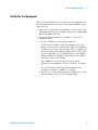
To test the cables
This test allows you to functionally verify U4201A logic
analyzer cables and Agilent E5379A probes.
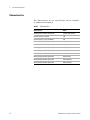
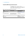
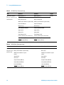
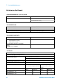
Table 9
Equipment Required to Test Cables
Equipment
Critical Specification
Recommended Part
Stimulus Board
No Substitute
16760-60001
Differential Probes
No Substitute
E5379A (Qty 2)
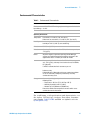
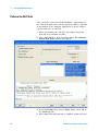
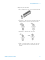
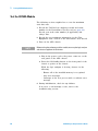
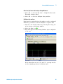
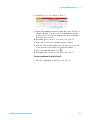
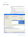
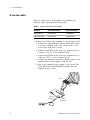
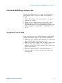
1 Connect the U4154A logic analyzer to the stimulus board.
a Connect the Agilent E5379A 90- pin differential probes
to the logic analyzer cable (also called “Pods”) to be
tested. Start with Pods 1 and 2.
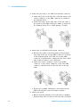
b Connect the E5379A probe from logic analyzer Pod 1 to
connector “Pod 4” on the stimulus board.
c Connect the E5379A probe from logic analyzer Pod 2 to
connector “Pod 5” on the stimulus board.
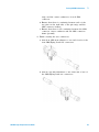
d Connect the stimulus board power supply output to the
stimulus board power supply connector J82.
e Plug in the stimulus power supply to line power. The
green LED DS1 should illuminate showing that the
stimulus board is active.
Pod 1
Pod 2
Pod 4
connector
76
Pod 5
connector
U4154A Logic Analyzer Service Guide