1
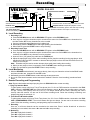
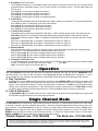
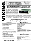
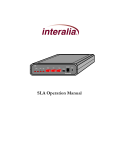
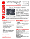
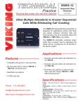
©
VIKING
Telecommunication Peripheral Products
Technical Practice
DVA-3003
3 Channel Digital
Voice Announcer
October 14, 2004
3 Channel Long Play Digital Announcer
The DVA-3003 is a
professional and cost-effective three channel
digital voice announcer specifically designed for ACD/UCD, hotel-motel wake up, auto
attendant, intercept, night message, information applications and other announcement
functions.
The DVA-3003 will increase call handling capacity by answering on demand or during
the first ring, automatically adjusting the announce cycle to the message length,
disconnecting on C.P.C. and providing instant “rewind” for the next caller.
The DVA-3003 is factory installed with 1 minute of record time per channel and may be
expanded to 4 minutes per channel using the ERAM-60 one minute memory expansion
kits. In applications where a single, longer message is required, the DVA-3003 can
also be configured as a single channel 3 to 12 minute announcer.
http://www.VikingElectronics.com
Features
• Record time expandable from 1 to 4 minutes per
channel
• Configurable as a 3-12 minute 1 channel
announcer
• Record and review announcements both locally
and remotely
• Tape jack to load prerecorded announcements
from a tape player
• Record 1, 2, or all 3 channels simultaneously
• Programmable ring delay for each channel
• Detects C.P.C. signal and disconnects
• Callers may be transferred after announcement
• Messages stored in Non-volatile memory (no
batteries required)
• Recognizes handshake signals from virtually
any PABX, Centrex or C.O.
• Provides both “Ring Trip” and 4 wire “E & M”
interface
• Recording volume level LED indicator for
consistently high-quality recordings
• One year warranty
Applications
Repetitive Announcing for:
•
•
•
•
•
School closings
• College events and schedules
Wake-up calls
• Bank rates/commodity prices
Movie theaters
• Help desks
Ski reports
• Night Message
ACD/UCD or any announce only application where a
message is repeated continuously and may require
frequent updating.
Specifications
Power: 120V AC/12V DC 500mA UL listed adapter provided or
power from 48V DC 0.1 A maximum
Dimensions: 480mm x 200mm x 45mm (19” x 8” x 1.75”)
Shipping Weight: 3 Kg (7lbs)
Environmental: 0° to 32° C (32° to 90° F) with 5% to 95% noncondensing humidity
Message Length: 1 minute/channel, field expandable to 2, 3, or 4
minutes/channel using model ERAM-60 memory kits in (1) minute
increments
Sampling Rate: 64 Kbps (equivalent)
Connections: Standard ring-trip with adjustable ring delay, 4-wire
E & M with 600 ohm audio and switch selectable protocol
Installation
A. 120V AC Operation
The DVA-3003 is provided with a 120VAC U.L. listed adaptor with a 12VDC 500mA output. The DVA-3003 requires a
24 hour unswitched 115VAC outlet. To protect the internal electronics, the installation of a surge protector is
recommended.
B. 48VDC Operation
Connect -48VDC and Earth Ground to the terminal block as shown below. Nominal current draw is less than 100mA.
If a power supply protection fuse is used in series with the -48V supply, a 500mA slow blow fuse is recommended.
The initial start up current can surge as high as 600-700mA.
CHANNEL 1
BUSY
600 OHM
E&M
CO/PABX
LINE
PROGRAMMING
PORT
E&M
PROTOCOLS
48V
USE ONLY LISTED
CLASS 2 POWER
SOURCE 12VDC, 500mA
MAX
ON
GND
POWER
OFF
5 6 7 8
Channel 1 ring trip
interface
Connect to “Ringing”
C.O. or PABX line.
Dry contact closure for “E &
M” busy signal or “A” Lead
control
for “ring trip”.
Earth GND (+) 6
1 - 48V
M Lead (Start) 5
2 E Lead (Busy)
Tip (600 ohm) 4
3 Ring (600 ohm)
VIKING ELECTRONICS HUDSON WI. 54016
or
Connect to “ringing”
C.O. line or PABX
ext. for remote
recording
and
programming when
using “E & M”
interface. If “Ring
Trip” interface is
used, channel 1 or
the Programming
Port may be used.
- 48VDC
Earth GND
(+)
120V AC
Channel 1 four wire E & M interface
Programming
A. Standard Ring Trip Interface (Two Wire)
Any ringing C.O./PABX line will be answered, given an announcement and released. The DVA-3003 is then
immediately ready to answer the next incoming call. Set the front panel DIP switches to RING TRIP for each channel
using “Ring Trip” Interface, then momentarily disconnect power. *
B. Continuous Play 4 Wire E & M Interface
Set the front panel DIP switches to E & M for each channel using E & M Interface. Set “E & M protocols” DIP
switches to “A” (DIP switches 5 and 6 off). Invert the START signal (DIP switch 7 on). *Momentarily disconnect the
power. The announcement will be repeated continuously on pins 3 and 4 (600 ohm output).
C. 600 Ohm 4 Wire E & M Protocols
First set the front panel DIP switches to E & M for each channel using E & M Interface, then momentarily disconnect
power.* Four different protocols are now switch selectable for changing E & M timing, plus the ability to invert the
START and/or BUSY signals.
Front Panel DIP Switches
Channel
1 2 3
E&M
ON
Rear Panel E $ M Protocols DIP Switches
SW 5
PROTOCOL “A” OFF
PROTOCOL “B” OFF
PROTOCOL “C” ON
For future use
ON
SW 6
OFF
ON
OFF
ON
ON
OFF
5 6 7 8
Ring
Trip
SW 7 Inverted START signal when “ON”
Single
Channel
SW 8 Inverted BUSY signal when “ON”
* A momentary power down allows the DVA-3003 to read the new DIP switch settings.
2
E&M
Protocols
D. 600 Ohm 4 Wire E & M Protocol Timing Specifications
1. “ON DEMAND”. Set DIP switches to protocol “A” (SW 5 and SW 6 - OFF).
Contact from PABX
GND screw terminal
or pin 6 on DVA-3003
Pin 5
Start
250msec. min.
Idle/open
250msec. max.
Pin 2
Idle/closed
Earth
GND
Busy output
from DVA-3003
GND (+)
M Lead (START)
Open
GND (+)
E Lead (BUSY)
Open
Announcement Duration
In Use
2. TYPE 5 E & M, WINK START. Set dip switches to protocol “B” (SW 5 - OFF, SW 6 - ON).
Contact from PABX
Pin 5
Start (M)
GND screw terminal
or pin 6 on DVA-3003
Idle/open
600ms
Pin 2
Wink (E)
Earth
GND
Busy output
from DVA-3003
GND (+)
M Lead (START)
Open
(Programmable)
B
O
M
Idle/closed
Announcement
*
E
O
M
B
O
M
*
*
GND (+)
E Lead (BUSY)
Open
3. DRUM RECORDER REPLACEMENT. Set dip switches to protocol “A” (SW 5 and SW 6 - OFF).
Pin 5
GND (+)
Start
M Lead (START)
GND screw terminal
(Connected to
or pin 6 on DVA-3003
earth GND)
600ms
(Programmable)
GND (+)
Pin 2
B
Announcement B Announcement B
E Lead (BUSY)
Busy output
O
O
O
Earth from DVA-3003
Open
M
M
M
GND
*
*
*
4. SINGLE PLAY ON DEMAND. Set dip switches to protocol “C” (SW 5 - ON, SW 6 - OFF).
Contact from PABX
GND screw terminal
or pin 6 on DVA-3003
Pin 5
Start
GND (+)
M Lead (START)
Open
Idle/open
250msec. max.
Pin 2
Idle/closed
Earth
GND
Busy output
from DVA-3003
Announcement
In Use
250msec.
min.
GND (+)
Announce E Lead (BUSY)
ment
Open
*NOTE: BOM = “Beginning Of Message” pulse. EOM = “End Of Message” pulse.
E. Using the DVA-3003 with Major PABX’S
Set Front Panel DIP Switches
to:
Manufacturer
Protocol Dip
Switches
Notes:
* Earth ground is the positive of the PABX system talk battery
Protocol A
ATT (Dimension,
Horizon, etc.
4 Wire E & M)
with inverted busy signal
E&M
ON
Use 4 Wire E & M Interface. Connections: T & R to pins 3 & 4, M to pin 5, E to pin
2 and Earth Ground* to GND screw terminal.
OFF
5 6 7 8
Protocol A
with inverted busy signal
ATT (System 75)
E&M
ON
Use 4 Wire E & M Interface and BUSY screw terminals. T & R to pins 3 & 4, SZ
to pin 5, SZ1 to GND screw terminal, and S and S1 to BUSY screw terminals.
OFF
5 6 7 8
3
Protocol A
ATT (System 85)
SN231 Circuit Pack
with inverted busy signal
E&M
ON
OFF
Use 4 Wire E & M Interface. Connections to SN231 Circuit Pack. T & R to pins 3
& 4, S to pin 5, and AL to pin 2. Set option switches 1 & 2 down and 3 up on the
Circuit Pack.
5 6 7 8
Protocol A
CONVEYANT
ON
E&M
OFF
5 6 7 8
Use 4 Wire E & M Interface. Connections: T & R to pins 3 & 4. Strap pin 5 (from
the DVA-3003) to GND screw terminal (of the DVA-3003). Don’t connect any
Earth Ground. RC-T1 (control input) lead to pin 2. CONVEYANT logic ground to 48V screw Terminal.
Protocol A
with inverted start signal
GTE
E&M
ON
Use 4 Wire E & M Interface. Connections: T & R to pins 3 & 4, M to pin 5, E to pin
2 and Frame Ground to GND screw terminal.
OFF
5 6 7 8
Protocol B
HARRIS (20-20)
ON
E&M
Use 4 Wire E & M Interface. Connections: T1 & R1 to pins 3 & 4. M to pin 5. E to
pin 2. Earth ground* to GND screw terminal.
OFF
5 6 7 8
Protocol A
HITACHI
(HCX 5000)
with inverted busy signal
E&M
ON
OFF
Use 4 Wire E & M Interface and BUSY screw terminals. Connections to ANIF
card: T & R to pins 3 & 4, M to pin 5, E & SG to BUSY screw terminals. Do not
strap SB & SG. SB to Ground screw terminal. Set ANIF for type 4 signaling.
Program connection class of “TKTH” in the HITACHI.
5 6 7 8
JISTEL (all models)
MITEL (all models)
ROLM (all models)
Ring
Trip
Protocol switches
are not functional
in Ring Trip mode
Use Ring Trip Interface. Connect T & R to pins 3 & 4 of the CO/PABX line jack.
Protocol C
N.E.C. (2400)
ON
E&M
OFF
Use 4 Wire E & M Interface. Connections to 40DT card: T1 & R1 to pins 3 & 4. M
to pin 5. Earth ground* to GND screw terminal.
5 6 7 8
Protocol A
NORTHERN (SL-1)
QPC74 Ran Truck
ON
E&M
OFF
5 6 7 8
Protocol A
NORTHERN (SL-1)
Universal trunk card
ON
E&M
OFF
Use 4 Wire E & M Interface. Connections to QPC74 RAN TRUNK circuit pack: T
& R to pins 3 & 4. CPO to pin 2. S/MBO to pin 5. Earth ground* to GND screw
terminal. Set C34 switch as follows: SW1.0 - closed, SW2.0 - closed, SW3.0 open, SW4.0 - closed. Programming the SL-1: The DVA-3003 emulates a Cook
201.
Use 4 Wire E & M Interface. Connections to Universal TRUNK card: T & R to
pins 3 & 4. Earth ground to GND screw terminal. Pin 5 to MB lead. Pin 2 to CP
lead. The DVA-3003 emulates a Audiochron RQ1-112.
5 6 7 8
Protocol A
SIEMENS
(SATURN)
ON
E&M
OFF
5 6 7 8
Protocol A
with inverted busy signal
SIEMENS
(40/80 Hybrid)
E&M
ON
OFF
Use 4 Wire E & M Interface. Connections to the TMBA-4 card: T & R to pins 3 &
4. MA to pin 5. Strap MA & EB together. Don't connect EA lead. Program Saturn
for “Recann” and “Demand” and set “System Message” to be a min. of 2 sec.
longer than actual announcement. Strap TMBA-4 for type 2 signaling.
Use 4 Wire E & M Interface and BUSY screw terminals. Connections to APB
(Applications Board): VT & VR to pins 3 & 4, RAN-CTL (#1-Yellow) to pin 5,
RAN-CTL (#2-Black) to GND screw terminal, RAN-SNS (#1-Blue) and RAN-SNS
(#2-White) to the BUSY screw terminals (reversible)
5 6 7 8
Protocol A
STARTEL
ON
E&M
Use 4 Wire E & M Interface. Connections: T & R to pins 3 & 4, M to pin 5, E to pin
2. No connection to the GND screw terminal.
OFF
5 6 7 8
Protocol A
STROMBERGCARLSON
(CO Switch)
with inverted busy signal
E&M
ON
OFF
Use 4 Wire E & M Interface. Connect T & R to pins 3 & 4, Earth Ground* to GND
screw terminal and pin 5 and E to pin 2. Strap the E & M Trunk card the same as
for an Audichron HQ1 112 Drum Announcer. Programming the CO switch: The
DVA-3003 emulates the Audichron Drum Announcer.
5 6 7 8
Protocol C
STROMBERGCARLSON
(DBX)
with inverted start and
busy signals
E&M
ON
Use 4 Wire E & M Interface. Connections: T & R to pins 3 & 4, M to pin 5, E to pin
2. Earth Ground* to GND screw terminal.
OFF
5 6 7 8
4
TADARAN
(All models)
Ring
Trip
Protocol switches
are not functional
in Ring Trip mode
Use Ring Trip Interface. Connect T & R to pins 3 & 4 of the CO/PABX line jack.
Program all DVA-3003 channels for ring delay of 2.
TOSHIBA
(Perception)
Ring
Trip
Protocol switches
are not functional
in Ring Trip mode
Use Ring Trip Interface. Connect T & R to pins 3 & 4 of the CO/PABX line jack.
Recording
VIKING ©
CHANNEL
123
E&M
RING
TRIP
REC/MON
ANNOUNCE
ON
MODEL DVA-3003
CHANNEL 1
TAPE IN
AUDIO
LEVEL
PLAY OFF REC
VOLUME
SINGLE
CHANNEL
REC/MON/ANNOUNCE Button
Selects Record or Announce Mode.
Handset Jack
Use a standard carbon handset.
1/8” Audio Input Jack
Permits downloading the announcement from a tape player.
START
PLAY/OFF RECORD Button
Press this button to select Play, Off or Record modes.
Playback Volume Adjusts the playback volume.
START Button Momentarily press to start and stop recording.
LED Flickers to indicate correct tape in volume level.
A. Local Recording
1. Recording Live
a. Press the REC/MON button until the REC/MON LED lights to select REC/MON mode.
b. One, any two, or all three channels may be recorded at the same time. Select REC for the channels to be
recorded. Select OFF for any channels not to be recorded.
c. Connect a standard carbon handset to the handset jack.
d. Momentarily press the START button and begin speaking into the handset.
e. When finished, press the START button to stop recording.
2. Recording from a Tape
a. Press the REC/MON button until the REC/MON LED lights to select REC/MON mode.
b. One, any two, or all three channels may be recorded at the same time. Select REC for the channels to be
recorded. Select OFF for any channels not to be recorded.
c. Insert a 3.5mm (1/8”) phono plug cable into the TAPE IN jack.
d. Adjust the tape player to the correct audio recording volume, play the recording from the tape player while
watching the audio level LED. Increase or decrease the tape players volume until the LED flickers but is not
mostly on or mostly off.
Note: A handset may be used to monitor the tape player while down loading the recording.
e. When you are ready to record, momentarily press the START button and begin recording.
f. When you are finished, press the START button to stop recording.
B. Local Monitoring
1. With the REC/MON mode selected, (see step a. above) place only one channel at a time into the PLAY mode
and place the other two channels into the OFF mode.
2. Momentarily press the START button to start and stop the announcement.
3. Any or all of the announcements can be rerecorded if needed. Follow the “local recording” procedures listed
above.
C. Remote Recording and Programming
Note: Remove the handset and tape input plug from the DVA-3003 before remote recording.
1. Ring Trip Interface Mode
To gain system access call (from a Touch Tone phone) the C.O. line or PABX extension connected to the DVA3003’s channel 1 CO/PABX LINE port. When the unit answers, enter a ✱. When the recording stops, enter your
six digit security code (factory set to 8,4,5,4,6,4,). Two beeps should then be heard, confirming the correct
security code was entered. You are now in the remote recording mode. Follow the recording, monitoring, and
programming steps in sections 3 - 5.
2. Four Wire E & M Interface Mode
To gain system access call (from a Touch Tone phone) the C.O. line or PABX extension connected to the DVA3003’s PROGRAMMING PORT. The unit will answer and give two beeps. You are now in the remote recording
mode. Follow the recording, monitoring, and programing steps in sections 3 - 5.
3. Recording
One, two, or all three channels can be recorded at the same time. Enter 1 and/or 2 and/or 3 to select the
channel(s) to be recorded, then enter a ✱ to start and a # to stop recording.
4. Monitoring
Enter ✱ 4 to play back channel 1.
Enter ✱ 5 to play back channel 2.
Enter ✱ 6 to play back channel 3.
5
5. Ring Delay (Ring Trip Interface)
The ring delay is factory set to “Immediate Answer” (unit answers in less than one full ring). The ring delay can be
programmed from “Immediate Answer” (0) to 9 rings. Example: If ring delay is set to 1, unit will answer after one
full ring cycle.
Enter (0-9), #, 1, 1 to program ring delay for channel 1.
Enter (0-9), #, 1, 2 to program ring delay for channel 2.
Enter (0-9), #, 1, 3 to program ring delay for channel 3.
Enter (0-9), #, 1, 4 to program ring delay for programming port.
6. E & M Timing
The Beginning Of Message and End Of Message pulse width is factory set to 600msec. This may be programmed
from 100msec. (enter 1) to 900msec. (enter 9) for each channel.
Enter (0-9), #, 2, 1 to program E & M timing for channel 1.
Enter (0-9), #, 2, 2 to program E & M timing for channel 2.
Enter (0-9), #, 2, 3 to program E & M timing for channel 3.
7. Transfer Phone Numbers
The transfer phone numbers are disabled from the factory. When a transfer phone number is programmed, the
DVA-3003 will perform a hook switch flash transfer (dialing the programmed phone number after the channel
announcement has been played. Note: To disable the hook switch flash transfer for a channel, leave the 16 digit
field blank.
Enter up to 16 digits (1-9), #, 0, 1 to program a transfer phone number for channel 1.
Enter up to 16 digits (1-9), #, 0, 2 to program a transfer phone number for channel 2.
Enter up to 16 digits (1-9), #, 0, 3 to program a transfer phone number for channel 3.
8. Message Repeat
Each channel has the ability to repeat the announcement up to 99 times before disconnecting or transferring an
answered call. The factory default for the message repeat count is set to 01.
Enter 2 digits (01-99), #, 3, 1 to set the message repeat count for channel 1.
Enter 2 digits (01-99), #, 3, 2 to set the message repeat count for channel 2.
Enter 2 digits (01-99), #, 3, 3 to set the message repeat count for channel 3.
9. Changing Your Security Code
It is recommended that you change the security code from the “845464” factory setting to your own personal 6 digit
number. To change the security code, enter your 6 digits _ _ _ _ _ _ plus #,4,7.
Note: The security code can not include a ✱ or #.
Operation
After the DVA-3003’s announcements have been recorded and monitored, place the unit into the ANNOUNCE mode.
Use DIP switches 1, 2, and 3 on the front panel to select Ring Trip Interface or E & M mode for channels 1, 2 and 3.
These switches are only read when first powered up. Momentarily disconnect power after changing the DIP switches.
A. Ring Trip Interface
A standard C.O. line or PABX extension should be connected to the CO/PABX LINE input jack for that channel. The
DVA-3003 will answer after the programmed ring delay, play the announcement for the message repeat count,
perform a hook switch flash transfer if a number is programmed, or disconnect. The BUSY screw terminals provide a
contact closure during the announcement. If the caller hangs up during the announcement, the DVA-3003 will detect
the C.P.C. signal (if present) and disconnect that line. It is now immediately ready for the next incoming call.
B. 4 Wire E & M Interface:
The 600 OHM E & M jack provides a 600 ohm “Dry” output. Refer to the protocol timing specifications on page 3 and
the PBX table on pages 4 and 5 for the control lead connections.
Single Channel Mode
The DVA-3003 may be configured as a single channel announcer with up to 12 minutes announcement time. In this mode
of operation, channels 2 and 3 are disabled, and channel 1 utilizes the combined digital announcement memory time of all
three channels. A stock DVA-3003 has a total of 3 minutes of single channel announcement memory. Viking model
ERAM-60 memory expansion chips can be installed to extend the announcement memory to a total of 12 minutes. Each
ERAM-60 chip will add one minute of announcement memory. To enable the single channel mode, set front panel
SINGLE CHANNEL DIP switch to ON, then momentarily disconnect power.
Product Support Line...(715) 386-8666
Fax Back Line...(715) 386-4345
Due to the dynamic nature of the product design, the information contained in this document is subject to change without notice. Viking
Electronics, its affiliates and/or subsidiaries assume no responsibility for errors and/or omissions contained in this information. Revisions of
this document or new editions of it may be issued to incorporate such changes.
6 Fax Back Doc # 127
Printed in the U.S.A.
ZF300720 Rev C