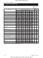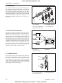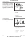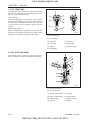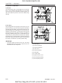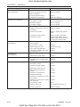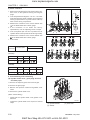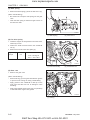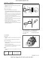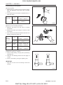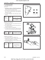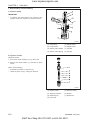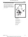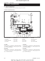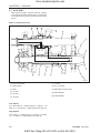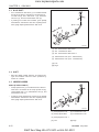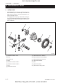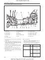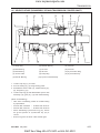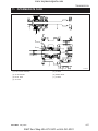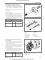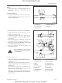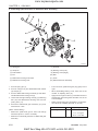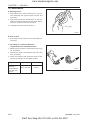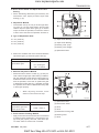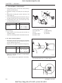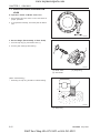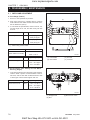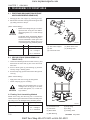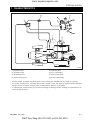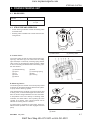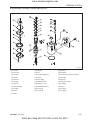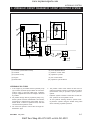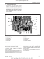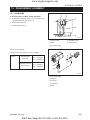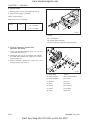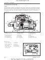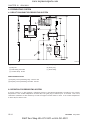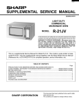
1
www.mymowerparts.com
8354/8404 SERVICE MANUAL
MTD Products, LLC Product Training and Education Department
FORM NUMBER 769-00902
K&T Saw Shop 606-678-9623 or 606-561-4983
www.mymowerparts.com
K&T Saw Shop 606-678-9623 or 606-561-4983
www.mymowerparts.com
CONTENTS
CHAPTER 1 GENERAL INFORMATION .......................................................................................... 1-1
1. TRACTOR VIEW ............................................................................................................................................... 1-3
2. TIGHTENING TORQUE FOR STANDARD BOLTS AND NUTS ................................................................. 1-4
2.1 TIGHTENING TORQUE .......................................................................................................................... 1-4
3. SPECIFICATIONS ............................................................................................................................................ 1-6
4. IDENTIFICATION ............................................................................................................................................. 1-8
4.1 ENGINE NUMBER ................................................................................................................................... 1-8
4.2 CHASSIS NUMBER OF THE TRACTOR(CHASSIS NUMBER OF THE MACHINE) ....................... 1-8
5. CAUTION BEFORE REPAIR .......................................................................................................................... 1-9
5.1 BEFORE REPAIR OR INSPECTION ..................................................................................................... 1-9
5.2 ASSEMBLY AND DISASSEMBLY ........................................................................................................... 1-9
5.3 PARTS TO BE REPLACED ..................................................................................................................... 1-9
5.4 PARTS ....................................................................................................................................................... 1-9
5.5 ASBESTOS PARTS ................................................................................................................................ 1-10
5.6 ELECTRICAL SYSTEM ......................................................................................................................... 1-10
5.7 TUBES AND RUBBERS ........................................................................................................................ 1-11
5.8 LUBRICANT ............................................................................................................................................ 1-11
6. REGULAR CHECK LIST ............................................................................................................................... 1-12
7. OIL & WATER SUPPLY LIST ........................................................................................................................ 1-13
CHAPTER 2 ENGINE SYSTEM ......................................................................................................... 2-1
1. GENERAL ......................................................................................................................................................... 2-3
1.1 APPEARANCE .......................................................................................................................................... 2-3
1.2 SPECIFICATIONS .................................................................................................................................... 2-4
1.3 PERFORMANCE CURVE ....................................................................................................................... 2-5
1.4 DIMENSIONS ........................................................................................................................................... 2-6
1.5 GENERAL WARNING .............................................................................................................................. 2-6
2. STRUCTURE AND FUNCTION ..................................................................................................................... 2-7
2.1 BODY ......................................................................................................................................................... 2-7
2.2 LUBRICATING SYSTEM ........................................................................................................................ 2-11
2.3 COOLING SYSTEM ................................................................................................................................ 2-13
2.4 FUEL SYSTEM ....................................................................................................................................... 2-15
3. DISASSEMBLING AND SERVICING ........................................................................................................... 2-24
3.1 TROUBLESHOOTING ........................................................................................................................... 2-24
3.2 SERVICING SPECIFICATIONS ............................................................................................................ 2-27
3.3 CHECKING, DISASSEMBLING AND SERVICING ............................................................................ 2-33
CHAPTER 3 CLUTCH ......................................................................................................................... 3-1
1. DISASSEMBLY AND ASSEMBLY .................................................................................................................... 3-3
1.1 DISASSEMBLY OF PANEL FRAME ........................................................................................................ 3-3
1.2 DISASSEMBLY OF FENDER AND STEPLADDER ASSEMBLY ......................................................... 3-6
K&T Saw Shop 606-678-9623 or 606-561-4983
www.mymowerparts.com
2. CLUTCH ............................................................................................................................................................ 3-8
2.1 CHARACTERISTICS ............................................................................................................................... 3-8
2.2 LINK STRUCTURE AND CONTROL ..................................................................................................... 3-9
2.3 TROUBLESHOOTING ........................................................................................................................... 3-10
2.4 SPECIFICATION .................................................................................................................................... 3-11
2.5 TIGHTENING TORQUE ........................................................................................................................ 3-11
2.6 DISASSEMBLY, MAINTENANCE ......................................................................................................... 3-12
CHAPTER 4 TRANSMISSION ........................................................................................................... 4-1
1. STRUCTURE ................................................................................................................................................... 4-3
2. POWER TRANSMISSION ............................................................................................................................... 4-4
2.1 MAIN TRANSMISSION ............................................................................................................................. 4-4
2.2 SHUTTLE .................................................................................................................................................. 4-7
2.3 HI-LO SHIFT ............................................................................................................................................. 4-8
2.4 MID PTO .................................................................................................................................................... 4-9
2.5 REAR PTO ................................................................................................................................................ 4-9
2.6 CREEPER SPEED (IF APPLICABLE ) ................................................................................................. 4-10
2.7 FRONT WHEEL DRIVE ......................................................................................................................... 4-10
3. TRANSMISSION SHIFT LINK STRUCTURE ............................................................................................. 4-11
3.1
MAIN SHIFT .......................................................................................................................................... 4-11
3.2
SHUTTLE SHIFT ................................................................................................................................. 4-11
3.3
HI-LO SHIFT ......................................................................................................................................... 4-12
3.4
PTO SHIFT ........................................................................................................................................... 4-12
3.5
CREEPER SPEED .............................................................................................................................. 4-12
3.6
MID PTO SHIFT ................................................................................................................................... 4-13
3.7
FRONT WHEEL DRIVE SHIFT .......................................................................................................... 4-13
4. PTO CLUTCH ................................................................................................................................................. 4-14
4.1
CHARACTERISTICS ........................................................................................................................... 4-14
4.2
HYDRAULIC CIRCUIT ........................................................................................................................ 4-14
4.3
OIL FLOW ............................................................................................................................................. 4-15
5. DIFFERENTIAL GEAR .................................................................................................................................. 4-16
5.1
STRUCTURE ....................................................................................................................................... 4-16
5.2
OPERATION ......................................................................................................................................... 4-17
6. TROUBLESHOOTING ................................................................................................................................... 4-19
7. MAINTENANCE SPECIFICATION ................................................................................................................ 4-20
8. TIGHTENING TORQUE ................................................................................................................................ 4-21
9. CLUTCH HOUSING ...................................................................................................................................... 4-22
9.1
TRANSMISSION OIL DRAINING ........................................................................................................ 4-23
9.2
CLUTCH HOUSING GROUP DISASSEMBLY ................................................................................. 4-23
10.CLUTCH HOUSING DISASSEMBLY ............................................................................................................... 4-28
10.1
FIRST STAGE (DISCONNECTION OF MAIN TRANSMISSION COVER) ..................................... 4-28
10.2
SECOND STAGE (DISCONNECTION OF PROPULSION SHAFT CASE) ................................... 4-29
K&T Saw Shop 606-678-9623 or 606-561-4983
www.mymowerparts.com
10.3 THIRD STAGE (DISASSEMBLY OF 25 GEAR SHAFT AND PROPULSION SHAFT 1) ........................... 4-30
10.4 FOURTH STAGE (DISASSEMBLY OF BEARING COVER ASSEMBLY) .......................................... 4-30
10.5 FIFTH STAGE (DISCONNECTION OF TRANSMISSION FORK) ..................................................... 4-31
10.6 SIXTH STAGE (DISASSEMBLY OF 22 GEAR SHAFT) ...................................................................... 4-32
10.7 SEVENTH STAGE (DISASSEMBLY OF MAIN TRANSMISSION COUNTER SHAFT) ................... 4-33
10.8 MAINTENANCE ...................................................................................................................................... 4-35
11.INTERMEDIATE CASE .................................................................................................................................. 4-37
11.1 DISASSEMBLY, ASSEMBLY .................................................................................................................. 4-38
11.2 MAINTENANCE ...................................................................................................................................... 4-43
12.TRANSMISSION CASE ................................................................................................................................. 4-46
12.1 DISASSEMBLY, ASSEMBLY .................................................................................................................. 4-46
12.2 MAINTENANCE ...................................................................................................................................... 4-56
CHAPTER 5 REAR AXLE ................................................................................................................... 5-1
1. STRUCTURE ................................................................................................................................................... 5-3
2. TIGHTENING TORQUE .................................................................................................................................. 5-4
3. SERVICE SPECIFICATION ............................................................................................................................ 5-5
4. DISASSEMBLY, ASSEMBLY ........................................................................................................................... 5-6
4.1 DISCONNECTION OF REAR AXLE GROUP ....................................................................................... 5-6
4.2 DISASSEMBLY OF REAR AXLE ............................................................................................................. 5-8
5. MAINTENANCE ................................................................................................................................................ 5-9
5.1 BEARING CHECK ................................................................................................................................... 5-9
5.2 GEAR CHECK .......................................................................................................................................... 5-9
5.3 CLEARANCE CHECK OF PLANETARY GEAR AND PLANETARY GEAR SHAFT ........................... 5-9
5.4 CHECK THRUST COLLAR FOR WORN .............................................................................................. 5-9
CHAPTER 6 BRAKE ........................................................................................................................... 6-1
1. STRUCTURE ................................................................................................................................................... 6-3
2. OPERATION ...................................................................................................................................................... 6-4
3. TROUBLESHOOTING ..................................................................................................................................... 6-5
4. MAINTENANCE SPECIFICATION .................................................................................................................. 6-6
5. TIGHTENING TORQUE .................................................................................................................................. 6-6
6. BRAKE PEDAL ................................................................................................................................................. 6-7
6.1 DISASSEMBLY, MAINTENANCE ........................................................................................................... 6-7
6.2 MAINTENANCE ........................................................................................................................................ 6-8
7. BRAKE CASE ................................................................................................................................................... 6-9
7.1 DISASSEMBLY AND ASSEMBLY ............................................................................................................ 6-9
7.2 OPERATION CHECK OF BRAKE CAM LEVER ................................................................................. 6-12
CHAPTER 7 FRONT AXLE ................................................................................................................. 7-1
1. STRUCTURE ................................................................................................................................................... 7-3
2. WHEEL ALIGNMENT ....................................................................................................................................... 7-4
3. TROUBLESHOOTING ..................................................................................................................................... 7-5
4. MAINTENANCE SPECIFICATION .................................................................................................................. 7-6
K&T Saw Shop 606-678-9623 or 606-561-4983
www.mymowerparts.com
5. TIGHTENING TORQUE .................................................................................................................................. 7-7
6. DISASSEMBLY, MAINTENANCE ................................................................................................................... 7-8
6.1 STRUCTURE ............................................................................................................................................ 7-8
7. DISCONNECTION OF FRONT AXLE GROUP ........................................................................................... 7-10
7.1 DISASSEMBLY, ASSEMBLY .................................................................................................................. 7-10
8. DISASSEMBLY OF FRONT AXLE ................................................................................................................ 7-12
8.1 FIRST STAGE (DISCONNECTION OF FRONT AXLE CASE AND BEVEL GEAR CASE) ................................. 7-12
8.2 SECOND STAGE (DISASSEMBLY OF FRONT AXLE) ...................................................................... 7-12
8.3 THIRD STAGE (DISASSEMBLY OF FRONT AXLE CASE) ................................................................ 7-13
8.4 FOURTH STAGE (DISASSEMBLY OF FRONT AXLE SUPPORT) ................................................... 7-14
8.5 FIFTH STAGE (DISASSEMBLY OF FRONT AXLE SUPPORT) ......................................................... 7-15
8.6 SIXTH STAGE (DISASSEMBLY OF BEVEL PINION SHAFT) ........................................................... 7-16
8.7 SEVENTH STAGE (DISASSEMBLY OF DIFFERENTIAL GEAR) ..................................................... 7-17
9. MAINTENANCE .............................................................................................................................................. 7-18
9.1 CLEARANCE CHECK BETWEEN CENTER PIN, FRONT AXLE SUPPORT BOSS AND
FRONT AND REAL BRACKETS .............................................................................................................. 7-18
9.2 CHECK FOR BACKLASH AND TOOTH CONTACTED IN FRONT AXLE CASE ............................ 7-18
9.3 CHECK FOR BEVEL GEAR BACKLASH AND TOOTH CONTACTED IN BEVEL GEAR CASE .. 7-19
9.4 CHECK FOR SHIM BETWEEN AXLE CASE SUPPORT AND FRONT AXLE CASE ............................... 7-19
9.5 CHECK FOR BACKLASH AND TOOTH CONTACTED BETWEEN BEVEL PINION SHAFT
AND SPIRAL BEVEL GEAR .................................................................................................................. 7-20
9.6 CLEARANCE CHECK BETWEEN DIFFERENTIAL PINION SHAFT AND
DIFFERENTIAL PINION ........................................................................................................................ 7-21
9.7 CLEARANCE CHECK BETWEEN FRONT DIFFERENTIAL CASE, DIFFERENTIAL CASE COVER
AND DIFFERENTIAL SIDE GEAR. ...................................................................................................... 7-21
9.8 CHECK FOR BACKLASH AND TOOTH CONTACTED BETWEEN DIFFERENTIAL PINION AND
DIFFERENTIAL SIDE GEAR ............................................................................................................... 7-22
CHAPTER 8 STEERING SYSTEM .................................................................................................... 8-1
1. CHARACTERISTICS ....................................................................................................................................... 8-3
2. HYDRAULIC CIRCUIT OF POWER STEERING SYSTEM ......................................................................... 8-4
3. GEAR PUMP ..................................................................................................................................................... 8-5
3.1 PUMP CHARACTERISTICS ................................................................................................................... 8-5
3.2 MAJOR SPECIFICATION ......................................................................................................................... 8-5
3.3 STRUCTURE OF GEAR PUMP .............................................................................................................. 8-5
3.4 OPERATION .............................................................................................................................................. 8-6
4. POWER STEERING UNIT .............................................................................................................................. 8-7
4.1 MAJOR SPEC. .......................................................................................................................................... 8-7
4.2 STRUCTURE AND OPERATION ........................................................................................................... 8-7
5. STEERING CYLINDER ................................................................................................................................... 8-8
5.1 STRUCTURE ............................................................................................................................................ 8-8
5.2 MAJOR SPECIFICATION ......................................................................................................................... 8-8
K&T Saw Shop 606-678-9623 or 606-561-4983
www.mymowerparts.com
6. OIL FLOW ......................................................................................................................................................... 8-9
6.1
IN NEUTRAL ........................................................................................................................................... 8-9
6.2
TURNING TO THE RIGHT .................................................................................................................... 8-9
6.3
TURNING TO THE LEFT ..................................................................................................................... 8-10
6.4
MANUAL STEERING ............................................................................................................................ 8-10
7. TROUBLESHOOTING ................................................................................................................................... 8-11
8. DISASSEMBLY, MAINTENANCE ................................................................................................................. 8-12
8.1
GEAR PUMP ......................................................................................................................................... 8-12
8.2
POWER STEERING UNIT ................................................................................................................... 8-14
8.3
STEERING CYLINDER ....................................................................................................................... 8-21
CHAPTER 9 HYDRAULIC SYSTEM ................................................................................................. 9-1
1. HYDRAULIC CIRCUIT DIAGRAM .................................................................................................................. 9-3
2. STRUCTURE ................................................................................................................................................... 9-4
3. HYDRAULIC CIRCUIT DIAGRAM OF 3-POINT HYDRAULIC SYSTEM ............................................................ 9-5
4. HYDRAULIC PUMP ......................................................................................................................................... 9-6
4.1 STRUCTURE OF HYDRAULIC PUMP .................................................................................................. 9-6
4.2 OPERATION .............................................................................................................................................. 9-6
5. OIL FILTER ....................................................................................................................................................... 9-7
5.1 STRUCTURE OF OIL FILTER ................................................................................................................ 9-7
5.2 FUNCTION AND OPERATION ................................................................................................................ 9-7
6. CONTROL VALVE (MLS VALVE) ..................................................................................................................... 9-8
6.1 STRUCTURE ............................................................................................................................................ 9-8
6.2 CIRCUIT DIAGRAM ................................................................................................................................. 9-8
6.3 OPERATION PRINCIPLE ........................................................................................................................ 9-9
7. RELIEF VALVE (HYDRAULIC BLOCK) ....................................................................................................... 9-12
8. HYDRAULIC CYLINDER .............................................................................................................................. 9-13
9. STRUCTURE AND OPERATION .................................................................................................................. 9-14
9.1 STRUCTURE .......................................................................................................................................... 9-14
9.2 OPERATION ............................................................................................................................................ 9-14
10.OUTSIDE HYDRAULIC EXTRACTION ....................................................................................................... 9-18
10.1 HYDRAULIC BLOCK
.............................................................................................................................
9-18
10.2 ACTING VALVE ....................................................................................................................................... 9-19
10.3 QUICK COUPLER ................................................................................................................................. 9-19
11. TOP LINK BRACKET DEVICE ..................................................................................................................... 9-20
11.1 STRUCTURE .......................................................................................................................................... 9-20
11.2 OPERATION ............................................................................................................................................ 9-20
12.TROUBLESHOOTING ................................................................................................................................... 9-21
13.MAINTENANCE SPECIFICATION ................................................................................................................ 9-22
13.1 3-POINT SYSTEM HYDRAULIC PUMP .............................................................................................. 9-22
13.2 RELIEF VALVE ....................................................................................................................................... 9-22
13.3 LINK CONTROL ..................................................................................................................................... 9-22
13.4 HYDRAULIC CYLINDER ...................................................................................................................... 9-23
K&T Saw Shop 606-678-9623 or 606-561-4983
www.mymowerparts.com
14.TIGHTENING TORQUE ................................................................................................................................ 9-24
15.DISASSEMBLY, ASSEMBLY ......................................................................................................................... 9-25
15.1 GEAR PUMP ........................................................................................................................................... 9-25
15.2 MAINTENANCE ...................................................................................................................................... 9-27
15.3 RELIEF VALVE ....................................................................................................................................... 9-27
15.4 HYDRAULIC CYLINDER ...................................................................................................................... 9-28
15.5 CHECK AND ADJUSTMENT ................................................................................................................. 9-34
CHAPTER 10 ELECTRIC SYSTEM ............................................................................................... 10-1
1. ELECTRONIC INSTRUMENTATION ........................................................................................................... 10-3
1.1 INSTRUMENT GAUGE .......................................................................................................................... 10-3
1.2 INDICATORS AND WARNING LIGHTS ............................................................................................... 10-4
2. TROUBLE SHOOTING .................................................................................................................................. 10-6
3. SERVICING SPECIFICATIONS ................................................................................................................... 10-8
4. MECHANISM ................................................................................................................................................... 10-9
4.1 STARTING SYSTEM .............................................................................................................................. 10-9
4.2 CHARGING SYSTEM .......................................................................................................................... 10-12
4.3 PREHEATING SYSTEM ...................................................................................................................... 10-14
4.4 FUSE .................................................................................................................................................... 10-15
4.5 GAUGE AND SENSORS .................................................................................................................... 10-16
5. MAIN CIRCUIT DIAGRAM .......................................................................................................................... 10-17
K&T Saw Shop 606-678-9623 or 606-561-4983
www.mymowerparts.com
CHAPTER 1
GENERAL INFORMATION
K&T Saw Shop 606-678-9623 or 606-561-4983
www.mymowerparts.com
K&T Saw Shop 606-678-9623 or 606-561-4983
www.mymowerparts.com
GENERAL INFORMATION
1. TRACTOR VIEW
615W101A
D615-W02 May-2003
K&T Saw Shop 606-678-9623 or 606-561-4983
1-3
www.mymowerparts.com
CHAPTER 1
8354/8404
2. TIGHTENING TORQUE FOR STANDARD BOLTS AND NUTS
2.1 TIGHTENING TORQUE
Screws, bolts and nuts whose tightening torques are not specified in this workshop manual should be tightened
according to the table below.
A. TIGHTENING TORQUE FOR STANDARD BOLTS AND NUTS
Grade
No grade 4T
Unit
Nominal
Diameter
M6
(6 mm, 0.24 in.)
M8
(8 mm, 0.31 in.)
M 10
(10 mm, 0.39 in.)
M 12
(12 mm, 0.47 in.)
M 14
(14 mm, 0.55 in.)
M 16
(16 mm, 0.63 in.)
M 18
(18 mm, 0.71 in.)
M 20
(20 mm, 0.79 in.)
4
7T
9T
7
9
N·m
Kgf·m
lbf·ft
N·m
Kgf·m
lbf·ft
N·m
Kgf·m
lbf·ft
7.85
0.80
5.79
9.80
1.00
7.24
12.3
1.25
9.1
~
~
~
~
~
~
~
~
~
9.30
0.95
6.87
11.2
1.15
8.32
14.2
1.45
10.5
17.7
1.8
13.0
23.6
2.4
17.4
29.4
3.0
21.7
~
~
~
~
~
~
~
~
~
20.5
2.1
15.2
27.4
2.8
20.2
34.3
3.5
25.3
39.2
4.0
29.0
48.1
4.9
35.5
60.8
6.2
44.9
~
~
~
~
~
~
~
~
~
45.0
4.6
33.2
55.8
5.7
41.2
70.5
7.2
52.1
62.8
6.4
46.3
77.5
7.9
57.2
103
10.5
76.0
~
~
~
~
~
~
~
~
~
72.5
7.4
53.5
90.1
9.2
66.5
117
12.0
86.8
108
11.0
79.6
124
12.6
91.2
167
17.0
123
~
~
~
~
~
~
~
~
~
125
12.8
92.5
147
15.0
108
196
20.2
144
167
17.0
123
196
20.0
145
260
26.5
192
~
~
~
~
~
~
~
~
~
191
19.5
141
225
23.0
166
303
31.0
224
245
25.0
181
275
28.0
203
343
35.0
254
~
~
~
~
~
~
~
~
~
284
29.0
210
318
32.5
235
401
41.0
297
334
34.0
246
368
37.5
272
490
50.0
362
~
~
~
~
~
~
~
~
~
392
40.0
289
431
44.0
318
568
58.0
420
* The figures on the table above are indicated the top of screw of bolt.
1-4
D615-W02 May-2003
K&T Saw Shop 606-678-9623 or 606-561-4983
www.mymowerparts.com
GENERAL INFORMATION
B. TIGHTENING TORQUE FOR STUDS
M8
11.7 ~ 15.7 N·m
1.2 ~ 1.6 kgf·m
8.6 ~ 11.5 lbf·ft
M10
24.5 ~ 31.4 N·m
2.5 ~ 3.2 kgf·m
18.0 ~ 23.1 lbf·ft
M12
34.3 ~ 49.0 N·m
3.4 ~ 5.0 kgf·m
25.3 ~ 36.1 lbf·ft
C. TIGHTENING TORQUE FOR HIGH PRESSURE HOSE UNION NUTS
Hose Size
(Inside Diameter: Inches)
1/8″
3/16″
1/4″
5/16″
3/8″
1/2″
5/8″, 3/4″
1″
Screw Size (PF)
1/8″
1/4″
1/4″
3/8″
3/8″
1/2″
3/4″
1″
Tightening (N·m)
9.8
24.5
24.5
49.0
49.0
58.8
117.7
137.3
1
2.5
2.5
5
5
6
12
14
7.2
18.0
18.0
36.1
36.1
43.3
86.8
101.2
Torque
(kgf·m)
(lbf·ft)
D615-W02 May-2003
K&T Saw Shop 606-678-9623 or 606-561-4983
1-5
www.mymowerparts.com
CHAPTER 1
8354/8404
3. SPECIFICATIONS
8354
Model
8404
Maximum PTO power
28.3 HP
33.4 HP
Engine GROSS power
33.5 HP
40.4 HP
3A165D
4A200
Engine
Model
Type
Indirect injection, vertical, water-cooled, 4-cycle diesel
Number of cylinders
Bore and stroke
3
4
87 × 92.4 mm
83 × 92.4 mm
(3.425 × 3.637 in.)
(3.268 × 3.637 in.)
1,647
1,999
Total displacement
Rated revolution
2,700 rpm
Injection timing
18° before T.D.C.
1-3-4-2
1-2-3
Injection order
Compression ratio
22 : 1
Lubricating system
Forced lubrication by trochoidal pump
Cooling system
Pressurized radiator, Forced circulation with water pump
12 V, 50 AMPS
Alternator
Weight (Dry)
Capacities
Dimensions
(with std.
Tires)
Fuel tank
(10.6 U.S.gal.)
5.8
(1.5 U.S.gal.)
7.0
(1.9 U.S.gal.)
Engine coolant
7.0
(1.9 U.S.gal.)
8.9
(2.4 U.S.gal.)
Transmission case
44 (11.6 U.S.gal.)
Front axle case
7.5
Overall length (without 3p)
3,357 mm (132.2 in.)
3,365 mm (132.5 in.)
Overall length (with 3p)
3,468 mm (136.5 in.)
3,550 mm (139.8 in.)
Overall width (minimum tread)
1,440 mm (56.7 in.)
1,505 mm (59.3 in.)
Overall height (Top of ROPS)
2,445 mm (96.5 in.)
2,465 mm ( 97.0 in.)
1,530 mm
1,545 mm
(60.2 9n.)
(60.8 in.)
1,668 mm (65.7 in.)
1,780 mm (70 in.)
Wheelbase
Ground clearance
Tread
Tire size
(Std. tires)
Clutch
Steering
1-6
40
Engine crankcase
Overall height
(Top of steering wheel)
Traveling
system
205 kg
179 kg
(2.0 U.S.gal.)
239 mm (9.4 in.)
257 mm (10.1 in.)
Front
1,235mm (48.4 in.)
1,235 mm (48.4 in.)
Rear
1,166 mm
1,158 mm
(45.9 in.)
(45.6 in.)
1,077 ~ 1,387 mm
1,158 ~ 1,467 mm
(42.4 ~ 54.6 in.)
(45.6 ~ 57.8 in.)
Front
7-16
8-16
Rear
12.4-24
13.6-24
Dry single stage
Hydrostatic steering system
D615-W02 May-2003
K&T Saw Shop 606-678-9623 or 606-561-4983
www.mymowerparts.com
GENERAL INFORMATION
Model
Traveling
system
8404
8354
Synchronized shuttle and transmission
Transmission
8 forward and 8 reverse speeds
(CR: 16 forward and 16 reverse speeds)
Brake
Traveling
Parking
Wet disc type
Connected with the traveling brake
Differential
Hydraulic
system
Bevel gear
Hydraulic lift control system
Pump
capacity
Position, Draft and Mixed control
Main pump
29.7
/min (7.8 U.S.gal.)
Power steering
pump
17.8
/min (4.7 U.S.gal.)
Three point hitch
SAE Category l
Maximum lifting capacity
(the end of lower ling)
PTO
No. of Remote control valve
ports(Option)
1,650 kg (3,638 lb)
1,550 kg (3,417 lb)
2 or 4
2 or 4
PTO shaft
SAE 1-3/8, 6 splines
Revolution
(independent PTO)
MID PTO
2,000 (2,542 rpm)
2,000 (2,542 rpm)
Rear PTO
540 (2,451 rpm)
540 (2,451 rpm)
3,100 mm
3,125 mm
(112.7 in.)
(123 in.)
Min. turning radius (without brake)
Traction system
Swing Draw-Bar
Weight (with ROPS)
Traveling speed
(at 2700 engine speed
with Std. tires)
Forward (creeper)
Reverse (creeper)
1,515 kg
1,665 kg
1.6 (0.21) ~ 23.2 km/h
1.7 (0.21) ~ 23.4 km/h
0.99 (0.13) ~ 14.41 mph
1.06 (0.13) ~ 14.54 mph
1.55 (0.20) ~ 21.4 km/h
1.56 (0.20) ~ 21.6 km/h
0.96 (0.12) ~ 13.30 mph
0.97 (0.12) ~ 13.42 mph
D615-W02 May-2003
K&T Saw Shop 606-678-9623 or 606-561-4983
1-7
www.mymowerparts.com
CHAPTER 1
8354/8404
4. IDENTIFICATION
4.1 ENGINE NUMBER
The engine serial number is stamped on the left side
of the cylinder block as shown in the figure. Engine
serial number provides important information.
615W102A
(1) Engine Serial Number
4.2 CHASSIS NUMBER OF THE
TRACTOR (CHASSIS NUMBER OF
THE MACHINE)
The chassis serial number of the tractor is stamped
on the left side of the front axle frame as shown in the
figure.
615W103A
(1) Manufacture Plate
(2) Transmission Serial Number
1-8
D615-W02 May-2003
K&T Saw Shop 606-678-9623 or 606-561-4983
www.mymowerparts.com
GENERAL INFORMATION
5. CAUTION BEFORE REPAIR
5.1 BEFORE REPAIR OR INSPECTION
1. In case of repair or inspection, locate the tractor
on the flat ground and pull the parking brake on.
2. Except for the items to be checked while the engine is running, be sure to stop the engine prior to
the work.
7. Finish assembly within 20 minutes after applying
sealant, after that, wait approx. 30 minutes later
before filling with oil.
5.3 PARTS TO BE REPLACED
3. When washing parts, use parts washing solvent
for industrial use (avoid using gasoline so to prevent environmental pollution). For the hydraulic
parts, apply designated hydraulic oil in washing.
4. When disassembling and assembling of the hydraulic apparatus, pay special attention not to allow dust or foreign substance to be attached or
intermixed.
5.2 ASSEMBLY AND DISASSEMBLY
To check a failure, try to find out its underlying cause. If
assembly or disassembly is needed, perform the work
in regular sequence as specified in this repair manual.
615W105A
The following parts should be replaced with new ones
when removed.
(1) Oil Seal
(2) Gasket
(3) Lock Nut
(4) Split Pin
(5) O-Ring
5.4 PARTS
615W104A
1. Disassembled parts shall be arranged orderly.
2. Sort out the parts to be replaced from the ones to
be reused.
CC
3. Be sure to use standard bolts and nuts that are
designated.
4. When assembling snap rings or spring pin types,
take care of assembling direction.
5. Split pin shall be spread surely not to escape when
installed.
6. When using sealant (such as gasket bond) on the
assembled surfaces, apply it evenly and consistently in a height of 3 ~ 5 mm (0.12 ~ 0.2 in.) on the
contact surface after removing the old bond and
cleaning the sealing surface with solvent. Apply
sealant on the center of the contact surface for the
space between the bolt holes of the contact
surface, and on the more inner side than the bolt
hole for the bolt area.
615W106A
When replacing parts, use only genuine Cub Cadet parts.
D615-W02 May-2003
K&T Saw Shop 606-678-9623 or 606-561-4983
1-9
www.mymowerparts.com
CHAPTER 1
8354/8404
5.5 ASBESTOS PARTS
Since dust out of asbestos fibrous parts is extremely
dangerous to your health, be sure to clean such parts
carefully, do not use compressed air.
5.6 ELECTRICAL SYSTEM
1. Check electrical wiring every year for any damage
or short circuit at the connections. In addition, have
your dealer inspection the electric system regularly.
2. Do not modify or reorganize the wiring of the electric field parts.
3. When disconnecting the battery cable, disconnect
negative cable first, reinstall the positive cable first
when reinstalling.
615W108A
5. When connecting the connector, insert it until it
snaps.
Disconnect battery negative terminal
•
Be sure to turn the starting key OFF
when connecting or disconnecting the
cable.
CAUTION
615W109A
6. Be sure not to drop sensors and relays which are
fragile.
7. When replacing a broken fuse with a new one, be
sure to use the fuse of capacity as specified.
615W107A
4. Remove the connector by pulling the plastic
section, not the wiring.
1-10
D615-W02 May-2003
K&T Saw Shop 606-678-9623 or 606-561-4983
www.mymowerparts.com
GENERAL INFORMATION
5.7 TUBES AND RUBBERS
5.8 LUBRICANT
615W111A
Be cautious of oil or other petroleum products on the
hoses and rubber parts, this may cause damage.
615W112A
When assembling and fixing, apply designated lubricant where specified in accordance with this repair
manual.
D615-W02 May-2003
K&T Saw Shop 606-678-9623 or 606-561-4983
1-11
www.mymowerparts.com
CHAPTER 1
8354/8404
6. REGULAR CHECK LIST
The first
Periodically
Since
Purchased
2yr
50 100 150 200 250 300 350 400 450 500 600 700 800 1500hr 1yr
Indicated Hours By Hour Meter
Check Items
Engine oil change
Engine oil filter cartridge change
Transmission oil change
Hydraulic oil filter change
Front axle oil change
Applying grease
Clutch pedal deflection
Brake pedal deflection
Fan belt tension
Fuel filter element change
Air cleaner element change
Battery electrolyte
Oil pressure fuel pipe’s inlet screw
if loosened
Radiator hose’s inlet bands if
loosened
Fuel pipe change
Radiator hose change
Hydraulic pipe joint change
Steering hose change
Toe-in
Deflection adjustment in front and
rear of the front axle
Direction control section
Bolt, nuts and pins of each part
Battery positive code adjustment &
change
Bleeding water in clutch housing
Check injection nozzle*
* Maintenance intervals in basis on the EPA instructions.
1-12
D615-W02 May-2003
K&T Saw Shop 606-678-9623 or 606-561-4983
www.mymowerparts.com
GENERAL INFORMATION
7. OIL & WATER SUPPLY LIST
Supply Items
Fuel
Capacity
40
(42.3 U.S.gal.)
Recommended Spec.
No. 2 - D diesel fuel
No. 1 - D diesel fuel if temperature
is below - 10 °C (14 °F)
Coolant
Engine Oil
3A165D
7.0
(1.85 U.S.gal.)
4A200B
8.9
(2.35 U.S.gal.)
3A165D
5.5
(1.45 U.S.gal.)
4A200B
Fresh clean water with antifreeze
SAE 15 W - 40
7.0
(1.85 U.S.gal.)
Transmission Oil
44
(11.6 U.S.gal.)
Universal tractor/transmission
Front Axle Section
7.8
(2.0 U.S.gal.)
hydraulic oil
Applying
Grease
Hydraulic control lever
shaft section
Small quantity
3 point link section
Until grease exits
SAE multi - purpose type grease
Brake pedal link section
Bracket section in front
and rear of the front axle
Clutch release hub
Supply when removed
D615-W02 May-2003
K&T Saw Shop 606-678-9623 or 606-561-4983
1-13
www.mymowerparts.com
K&T Saw Shop 606-678-9623 or 606-561-4983
www.mymowerparts.com
CHAPTER 2
ENGINE SYSTEM
K&T Saw Shop 606-678-9623 or 606-561-4983
www.mymowerparts.com
K&T Saw Shop 606-678-9623 or 606-561-4983
www.mymowerparts.com
ENGINE SYSTEM
1. GENERAL
1.1 APPEARANCE
615W201A
The DAEDONG A series engines are vertical, watercooled, 4-cycle, three or four cylinders diesel engines,
they concentrate DAEDONG’s foremost technologies.
With swirl combustion chamber, bosch K type fuel injection pump, well-balanced designs, they feature
greater power, low fuel consumption, less vibration and
noise, and low emission.
D615-W02 May-2003
K&T Saw Shop 606-678-9623 or 606-561-4983
2-3
www.mymowerparts.com
CHAPTER 2
8354/8404
1.2 SPECIFICATIONS
Model
Type
Number of cylinder
Bore and stroke
Total Displacement
3A165D
4A200B
Vertical, water-cooled,
Vertical, water-cooled,
4-cycle diesel engine
4-cycle diesel engine
3
4
87 x 92.4 mm
83 x 92.4 mm
3.43 x 3.64 in.
3.27 x 3.64 in.
1,647 cc
1,999 cc
3
122.0 in3
100.5 in
Combustion
Spherical type
Spherical type
33.5/2,700 HP/rpm
40.4/2,700 HP/rpm
30.0/2,700 kW/rpm
36.2/2,700 kW/rpm
Maximum idling speed
2,900 rpm
2,900 rpm
Minimum idling speed
850 ~ 900 rpm
850 ~ 900 rpm
1-2-3
1-3-4-2
Counterclockwise
Counterclockwise
(viewed from flywheel side)
(viewed from flywheel side)
Bosch K TYPE mini pump
Bosch K TYPE mini pump
140 ~ 150 kgf/cm²
140 ~ 150 kgf/cm²
13.73 ~ 14.71 MPa
13.73 ~ 14.71 MPa
1,991 ~ 2,133 psi
1,991 ~ 2,134 psi
18 °
18 °
22 : 1
22 : 1
Diesel fuel
Diesel fuel
Chamber
Gross power
Order of firing
Direction of rotation
Injection pump
Injection pressure
Injection timing
(Before T.D.C)
Compression Ratio
Fuel
Lubricant
Dimensions
(length x width x height)
Dry weight
Engine oil SAE 15W-40
Engine oil SAE 15W-40
722.3 x 488.1 x 729.9 mm
817.3 x 488.1 x 735.8 mm
28.4 x 19.2 x 28.7 in.
32.2 x 19.2 x 29.0 in.
179 kg
183 kg
395 lbs.
403 lbs.
* NOTE: Change of parts are not subject to advance notice.
2-4
D615-W02 May-2003
K&T Saw Shop 606-678-9623 or 606-561-4983
www.mymowerparts.com
ENGINE SYSTEM
1.3 PERFORMANCE CURVE
615W203A
D615-W02 May-2003
K&T Saw Shop 606-678-9623 or 606-561-4983
615W204A
2-5
www.mymowerparts.com
CHAPTER 2
8354/8404
1.4 DIMENSIONS
615W206A
3A165D (mm)
(in.)
4A200B (mm)
(in.)
A
B
C
D
E
F
G
H
I
J
602.3
722.3
280.0
400.0
488.1
251.6
729.9
259.7
240.0
315.0
95.0
23.71
28.44
11.02
15.75
19.22
9.91
28.74
10.00
9.45
12.40
3.74
697.3
817.3
280.0
400.0
488.1
251.6
735.8
259.7
240.0
321.0
92.0
27.45
32.18
11.02
15.75
19.22
9.91
28.97
10.22
9.45
12.64
3.62
K
1.5. GENERAL WARNING
•
When disassembling, arrange each part on a clean
place. Do not mix them up. Replace bolts and nuts
where they were.
•
When servicing electrical parts or connecting instruments to electrical equipment, first disconnect the
battery negative terminal.
•
Replace gaskets or O-rings with new ones when
reassembling, and apply grease on a O-ring and
the oil seal when reassembling.
•
When exchanging parts, use Cub Cadet parts to
maintain engine performance and safety.
•
To prevent oil and water leakage, apply non-drying
adhesive to the gaskets according to this manual
before reassembling.
•
When hoisting up the engine, use the hook provided on the cylinder head.
•
When reinstalling the engine, use the hook provided
on the cylinder head.
•
When installing external cir-clips or internal cir-clips,
direct corner end to the non-loosening direction.
2-6
D615-W02 May-2003
K&T Saw Shop 606-678-9623 or 606-561-4983
www.mymowerparts.com
ENGINE SYSTEM
2. STRUCTURE AND FUNCTION
2.1 BODY
A. CYLINDER HEAD
The cylinder head is made of special alloy cast iron
which can resist high temperature and pressure
caused by combustion. The inlet and exhaust ports are
arranged cross-flow type to get high combustion efficiency by protecting the suction air from being heated
and expanded by heated exhaust air.
The DAEDONG vortex type combustion chamber is designed for high combustion efficiency and reducing fuel
consumption. The glow plug assures easier than ever
engine starts even at -15 °C (5 °F).
615W207A
(1) Combustion Chamber
(2) Inlet Port
(3) Exhaust Port
(4) Injection Nozzle
(5) Glow Plug
(6) Cylinder Head
615W208A
B. CYLINDER BLOCK
The engine has a high durability tunnel-type cylinder
block. Furthermore, liner less type, allows effective cooling, less distortion, and greater wear-resistance using
special material. The noise is reduced to a minimum
because each cylinder has its chamber.
615W209A
D615-W02 May-2003
K&T Saw Shop 606-678-9623 or 606-561-4983
2-7
www.mymowerparts.com
CHAPTER 2
8354/8404
C. CRANKSHAFT
The crankshaft is made of forged steel and the journals,
the crankpins and the bearing surface for the oil seal
are induction-hardened to increase wear resistance.
Each crankshaft journal is supported by the main bearing case (3) having a bearing inside. The front bearingcrankshaft bearing (2) is a solid type bushing and rear
and intermediate bearings are a split type. The
crankshaft, crankshaft bearings have oil holes for lubricant flow.
615W210A
(1) Crankshaft
(2) Crankshaft Bearing 1
(4) Crankshaft Bearing 2
(5) Thrust Bearing
(3) Main Bearing Case
D. PISTON AND PISTON RINGS
The piston is made of an aluminum alloy which is temperature and pressure resistant. Three rings are installed in the grooves of the piston. The top ring (1) is a
keystone type, which can withstand heavy loads, and
the barrel face on the ring fits well to the cylinder wall.
The second ring (2) is an undercut type, which prevents the oil from being carried up. The oil ring (3) has
chambered contact faces and an expander ring, which
increase the pressure of the oil ring against the cylinder wall to scrape the oil. The top ring is plated with
hard chrome to increase wear resistance (The ring of
4A200T engine is made of a special steel).
615W211A
(1) Top Ring
(3) Oil Ring
(2) Second Ring
E. CONNECTING ROD
The connecting rod (2), which converts the reciprocating motion of the pistons caused by the fuel combustion into the rotating motion of the crankshaft, is made
of hard forged steel. The connecting rod has bearings
at both ends. The small end has a solid type bearing
(small end bushing (2)) and the big end has a split
type bearing (crankpin bearing (3)).
615W212A
(1) Small End Bushing
(3) Crankpin Bearing
(2) Connecting Rod
2-8
D615-W02 May-2003
K&T Saw Shop 606-678-9623 or 606-561-4983
www.mymowerparts.com
ENGINE SYSTEM
F. CAMSHAFT
The camshaft (3) is made of forged steel and its journal and cams are hardened to increase wear
resistance. The cams on the camshaft open and close
the inlet and exhaust valves with the push rods and
rocker arms. The journals and their bearings are forcelubricated.
615W213A
(1) Cam Gear
(3) Camshaft
(2) Camshaft Stopper
G. FUEL CAMSHAFT
This fuel camshaft is made of forged steel and its cams
are hardened and tempered to increase wear
resistance. The cams on the fuel camshaft (1) drive
the injection pump and the fuel transfer pump. The
governor balls are installed on the fuel camshaft to
control the engine speed.
615W214A
(1) Fuel Camshaft
(2) Injection Pump Gear
H. ROCKER ARM ASSEMBLY
The rocker arm assembly includes the rocker arms (1)
and an adjusting screw (3), which is at the end of rocker
arm and rests on the push rod, rocker arm brackets (4)
and rocker arm shaft (5). The rocker arms are activated
by the reciprocating motion of the push rods and open
or close the inlet and exhaust valves. The rocker arm
and other parts are lubricated through the drilled holes
of the brackets and the rocker arm shaft.
615W215A
(1) Rocker Arm
(4) Rocker Arm Bracket
(2) Lock Nut
(5) Rocker Arm Shaft
(3) Adjusting Screw
D615-W02 May-2003
K&T Saw Shop 606-678-9623 or 606-561-4983
2-9
www.mymowerparts.com
CHAPTER 2
8354/8404
I. INLET AND EXHAUST VALVES
The valve and its guide of the inlet are different from
those for the exhaust. Other parts, such as the spring,
spring retainers, valve spring collets, valve stem seals
are the same for both the inlet and the exhaust. All
contact or sliding surfaces are hardened to increase
wear resistance.
615W216A
(1) Valve Spring Collet
(4) Valve Stem Seal
(2) Valve Spring Retainer (5) Exhaust Valve
(3) Valve Spring
(6) Inlet Valve
J. TIMING GEARS
The crankshaft drives the oil pump and the idle gear
engaged fuel camshaft and camshaft. The timings for
opening and closing the valves is extremely important
to achieve effective air inlet and sufficient gas exhaust.
The appropriate timing can be obtained by aligning the
mark on the crankshaft gear (6) with one the idle gear
(5), idle gear with camshaft gear, idle gear with injection pump gear, when assembling.
615W217A
(1) Injection Pump Gear
(5) Idle Gear
(2) Fuel Camshaft
(6) Crankshaft Gear
(3) Camshaft Gear
(7) Crankshaft
(4) Camshaft
K. FLYWHEEL
The flywheel is installed on the rear end of the
crankshaft. Its inertia keeps the flywheel turning at a
constant speed, while the crankshaft tends to speed
up during the power stroke and to slow down during
other stokes. The flywheel has a ring gear (1), which
mesh with the drive pinion of the starter. The flywheel
has also marks “TC” and “FI” on its outer rim. The mark
TC shows the piston’s top dead center and the mark FI
shows the fuel injection timing, when they are aligned
with the mark of window on the clutch housing.
615W218A
(1) Ring Gear
(3) Crankshaft
(2) Flywheel
2-10
D615-W02 May-2003
K&T Saw Shop 606-678-9623 or 606-561-4983
www.mymowerparts.com
ENGINE SYSTEM
2.2 LUBRICATING SYSTEM
A. FLOW OF LUBRICATING OIL
The lubricating oil is forced to each journal through the
oil passages of the cylinder block, cylinder head and
shafts. The oil, splashed by the crankshaft or thrown
off from the bearings, lubricates other engine parts
such as the push rods (11), tappets (12), camshaft
(14), and crankshaft (15).
615W219A
(1) Piston
(9) Rocker Arm Shaft
(2) Idle Gear
(10) Rocker Arm
(3) Oil Pump
(11) Push Rod
(4) Relief Valve
(12) Tappet
(5) Strainer
(13) Oil Pressure Switch
(6) Oil Filter Element
(14) Camshaft
(7) Bypass Valve
(15) Crankshaft
(8) Oil Pan
B. OIL PUMP
The oil pump is a gear type. Whose rotors have trochoid lobes. The inner rotor (3) has 4 lobes and the
outer rotor (4) has 5 lobes, and they are eccentrically
engaged with each other. The inner rotor, which is driven
by the crankshaft through the gears, rotates the outer
rotor in the same direction, varying the space between
the lobes.
While the rotors rotate from (A) to (B), the space leading to the inlet port increases, which causes the oil to
flow through the inlet port.
When the rotors rotate to (C), the port to which the space
leads is changed from inlet to outlet.
At (D), the space decreases and oil is discharged
through the outlet port.
615W220A
(1) Inlet
(3) Inner Rotor
(2) Outlet
(4) Outer Rotor
D615-W02 May-2003
K&T Saw Shop 606-678-9623 or 606-561-4983
2-11
www.mymowerparts.com
CHAPTER 2
8354/8404
C. OIL FILTER AND RELIEF VALVE
The lubricating oil force-fed by the pump is filtered by
the filter cartridge, passing through the filter element
from the outside to the inside. When the filter element
accumulates dirt and the pressure difference between
the inside and the outside rises more than 98 kPa
(1.0 kgf/cm², 14 psi), the bypass valve (1) opens to
allow the oil to flow from the inlet line to outlet line,
bypassing the filter element. The relief valve ball (4) in
the inlet line allows oil to prevent damage to the lubricating system, when the oil pressure rises more than
441 kPa (4.5 kgf/cm², 64 psi).
615W221A
(1) Bypass Valve
(2) Bypass Adjusting Spring
(3) Filter Element
(4) Relief Valve Ball
(5) Relief Adjusting Spring
(a) To Idle Gear, Camshaft and Rocker Arm
(b) From Oil Pump
(c) To Crankshaft Journal Crankpin
(d) Drain of Relief Valve
D. OIL PRESSURE SWITCH
The oil pressure switch is installed on the cylinder
block and leads to the oil passage of the lubricating
oil. When the oil pressure falls below the specified
value, the contacts of the oil pressure switch closes to
turn on the warning lamp (1).
615W222A
(A) At Lower Oil Pressure
(49 kPa (0.5 kgf/cm², 7 psi) or less)
(B) At Proper Oil Pressure
(1) Warning Lamp
(6) Rubber Washer
(2) Battery
(7) Oil Pressure
(3) Contact Movable
(8) Cylinder Block
(4) Contact Cup
(9) Pressure
(5) Diaphragm
2-12
D615-W02 May-2003
K&T Saw Shop 606-678-9623 or 606-561-4983
www.mymowerparts.com
ENGINE SYSTEM
2.3 COOLING SYSTEM
A. FLOW OF COOLING WATER
The cooling system consists of a radiator (5), a centrifugal water pump (7), a cooling fan (6) and a thermostat (2). The water is cooled as it flows through the
radiator core, and the fan behind the radiator pulls the
cooling air through the radiator core. The water pump
receives water from the radiator or from the cylinder
head and forces it into cylinder block. The thermostat
open or closes according to the water temperature.
When the water temperature is high, the thermostat
opens to allow the water to flow from the cylinder block
to the radiator. When the water temperature is low, the
thermostat closes and the flow stays within the block.
The opening temperature of the thermostat is approx.
71 °C (160 °F).
615W223A
(1) Water Return Pipe
(2) Thermostat
(3) Cylinder Head Water Jacket
(4) Cylinder Block Water Jacket
(5) Radiator
(6) Cooling Fan
(7) Water Pump
B. WATER PUMP
The water pump is driven with the fan drive pulley, which
is on the water pump shaft and driven by the crankshaft
with a belt. The water pump sucks the cooled water,
forces into the cylinder block and draws out the hot
water to the radiator repeatedly. The mechanical seal
(3) prevents the water from entering the bearing (1).
615W224A
(a) From the Thermostat
(b) To the Cylinder Block
(c) From the Radiator
(1) Bearing
(3) Mechanical Seal
(2) Pump Body
(4) Pump Impeller
D615-W02 May-2003
K&T Saw Shop 606-678-9623 or 606-561-4983
2-13
www.mymowerparts.com
CHAPTER 2
8354/8404
C. THERMOSTAT
The thermostat is wax pellet type, which controls the
flow of the cooling water to the radiator to keep the
proper temperature. The case has a seat (1) and the
pellet has a valve (2). The spindle attached to the case
is inserted into the synthetic rubber in the pellet. The
pellet is charged with wax.
(A) At Low Temperature (Lower than 71 °C (160 °F)).
The valve (2) is seated by the spring (7) and the cooling water circulates in the engine through the water
return pipe but does not enter the radiator.
(B) At High Temperature (Higher than 71 °C (160 °F)).
As the water temperature rises, the wax in the pellet (3)
turns liquid and expands, repelling the spindle.
The pellet lowers and the valve (2) opens to send the
cooling water to the radiator.
615W225A
(1) Seat
(6) Wax (Solid)
(2) Valve
(7) Spring
(3) Pellet
(8) Leak Hole
(4) Spindle
(9) Wax (Liquid)
(5) Synthetic Rubber
D. RADIATOR
The radiator core consists of water carrying tubes (2)
with fins (3) at a right angle to it. The water in the radiator is cooled by the air flowing through between the
tube wall and the fin.
615W226A
(1) Cooling Water
(3) Fin
(2) Tube
E. RADIATOR CAP
The pressure type cap is installed on the radiator, which
prevents the pressure difference between the inside
and the outside of the radiator from deforming the radiator.
(A) At High Pressure
(Higher than 88 kPa (0.9 kgf/cm², 13 psi)
When the water temperature rises and the pressure in
the radiator increases above the specified pressure,
the pressure valve (1) opens to reduce the internal
pressure.
(B) At Low Pressure.
When the water temperature falls and a vacuum is
formed in the radiator, the vacuum valve (2) opens to
allow the water to enter the radiator.
2-14
615W227A
(1) Pressure Valve
(2) Vacuum Valve
D615-W02 May-2003
K&T Saw Shop 606-678-9623 or 606-561-4983
www.mymowerparts.com
ENGINE SYSTEM
2.4 FUEL SYSTEM
A. FLOW OF FUEL
The fuel is fed from the fuel tank (1) through the fuel
feed pump (7) to the injection pump (3) by the fuel filter
(2). The injection pump force-feds the fuel through the
injection nozzles (5), which inject the fuel into the cylinders for combustion. The excessive fuel from the injection pump to the injection nozzles (5), which inject the
fuel into the cylinders for combustion. The excessive
fuel from the injection pump to the injection nozzles is
collected in the fuel overflow pipes (6) and returns to
the fuel tank.
615W228A
(1) Fuel Tank
(5) Injection Nozzle
(2) Fuel Filter
(6) Fuel Overflow Pipe
(3) Injection Pump
(7) Fuel Feed Pump
(4) Injection Pipe
B. FUEL FILTER
The fuel filter removes dirt and water with its fine filter
paper, which collects particles of 90 microns (0.0034 in.)
at 20 kPa (0.2 kgf/cm², 3 psi). The fuel from the fuel
feed pump is filtered by the filter element (6), while
flowing through the filter body (3) has an air vent (2) to
return the air tin the fuel to the fuel tank to prevent the
engine from stopping or running irregularly.
615W229A
(a) To Fuel Tank
(b) From Fuel Feed Pump
(c) To Injection Pump
(1) Cock
(4) Retainer Ring
(2) Air Vent
(5) Pot
(3) Filter Body
(6) Filter Element
D615-W02 May-2003
K&T Saw Shop 606-678-9623 or 606-561-4983
2-15
www.mymowerparts.com
CHAPTER 2
8354/8404
C. FUEL FEED PUMP
The diaphragm (6) is linked to the tappet (3) with the
push rod (2). The tappet is reciprocated by the eccentric cam on the fuel camshaft (7).
(A) Inlet Stroke
When the diaphragm is pulled down by the spring,
vacuum in the chamber (5) causes the outlet valve (4)
to close and the atmospheric pressure in the fuel tank
to force the fuel into the chamber, opening the inlet
valve (1).
(B) Discharge Stroke
When the diaphragm is pushed up by the cam, the
pressure in the chamber causes the inlet valve to close
and forces out the fuel, opening the outlet valve.
615W230A
(a) From Fuel Tank
(b) To Fuel Filter
(1) Inlet Valve
(5) Chamber
(2) Push Rod
(6) Diaphragm
(3) Tappet
(7) Fuel Camshaft
(4) Outlet Valve
D. FUEL INJECTION PUMP
The injection pump is Bosch K type mini injection
pump. It features a compact and light weight design.
615W240A
(a) To Injection Nozzle
(b) From Fuel Filter
2-16
(1) Delivery Valve Holder
(5) Plunger
(2) Delivery Valve Spring
(6) Control Rack
(3) Delivery Valve
(7) Plunger Spring
(4) Cylinder
(8) Tappet
D615-W02 May-2003
K&T Saw Shop 606-678-9623 or 606-561-4983
www.mymowerparts.com
ENGINE SYSTEM
a . Pump Element
The pump element (1) consists of a plunger (3) and
cylinder (2), their sliding surfaces are precision machined to maintain fuel tightness. The plunger (3) fits
in the control sleeve (5) at the driving surface (7). The
sleeve is engaged with the control rack, which rotate
the plunger in the cylinder to control the amount of fuel
delivery.
615W241A
(1) Pump Element
(5) Control Sleeve
(2) Cylinder
(6) Control Groove
(3) Plunger
(7) Driving Surface
(4) Feed Hole
b. Operation of Pump Element
(A) Before Delivery
As the taper lowers, the plunger (2) lowers and fuel is
drawn into the delivery chamber (1) through the feed
hole (4) from the fuel chamber (5).
(B) Beginning of Delivery
When the plunger is pushed up by the cam and the
head of the plunger closes the feed hole (4), the pressure in the delivery chamber (1) rises to push the delivery valve (3) open.
(C)Delivery
While the plunger (2) is rising, delivery of fuel continues.
(D)End of Delivery
When the plunger rises further and the control groove
(6) on its periphery meets the feed hole, the fuel returns to the fuel chamber (5) from the delivery chamber
(1) through the control groove (6) and the feed hole (4).
615W242A
(1) Delivery Chamber
(4) Feed Hole
(2) Plunger
(5) Fuel Chamber
(3) Delivery Valve
(6) Control Groove
D615-W02 May-2003
K&T Saw Shop 606-678-9623 or 606-561-4983
2-17
www.mymowerparts.com
CHAPTER 2
8354/8404
c. Amount of Fuel Delivery
(A) No Fuel Delivery
At the engine stop position of the control rack (3), the
lengthwise slot (1) on the plunger (2) aligns with the
feed hole (5). The delivery chamber (4) is led to the
feed hole during the entire stroke of the plunger. The
pressure in the delivery chamber does not build up
and no fuel is forced to the injection nozzle.
(B) Fuel Delivery
The plunger is rotated by the control rack and the feed
hole is not aligned with the lengthwise slot. When the
plunger is pushed up, the feed hole is closed by the
plunger. The pressure in the delivery chamber builds
up and forces the fuel to the injection nozzle until the
control groove (6) meets the feed hole. The amount of
the fuel to be forced into the nozzle corresponds to
distance A.
615W243A
(1) Slot
(4) Delivery Chamber
(2) Plunger
(5) Feed Hole
(3) Control Rack
(6) Control Groove
d. Delivery Valve
The delivery valve prevents the fuel in the injection pipe
from flowing back into the delivery chamber and the
fuel in the injection nozzle from dribbling after injection.
615W244A
2-18
(1) Valve Spring
(4) Fuel Chamber
(2) Valve
(5) Valve Face
(3) Valve Seal
(6) Relief Plunger
D615-W02 May-2003
K&T Saw Shop 606-678-9623 or 606-561-4983
www.mymowerparts.com
ENGINE SYSTEM
E. FUEL INJECTION NOZZLE
The nozzle is a throttle-type one. It features low fuel
consumption and works well with DAEDONG combustion chamber. The nozzle valve opening pressure is
about 13.7 to 14.7 MPa (140 to 150 kgf/cm², 1991 to
2134 psi), the pressure overcomes the counterforce of
nozzle valve spring, and push the valve up instantly, the
fuel is then injected in a proper quantity into the swirling air in the combustion chamber for combustion. Addition or reduction of adjusting can adjust the opening
pressure. A washer of 0.1 mm corresponds to 980 kPa
(10 kgf/cm², 142 psi) change in opening pressure. The
heat seal is employed to improve the durability and
reliability of the nozzle.
615W245A
(1) Nozzle Holder Ass’y
(6) Nozzle Body
(2) Adjusting Washer
(7) Needle Valve
(3) Nozzle Spring
(8) Heat Seal
(4) Push Rod
(9) Packing
(5) Retaining Nut
F. GOVERNOR AND IDLE COMPENSATING
a . Disassembled View
The governor serves to keep engine speed constant by
automatically adjusting the amount of fuel supplied to
the engine according to changes in the load. The engine employs an all-speed governor which controls
centrifugal force of the steel ball (13) weight, produced
by rotation of the fuel camshaft (9), and tension of the
governor spring 1 (2) and 2 (3) are balanced.
615W246A
(1) Start Spring
(2) Governor Spring 1
(3) Governor Spring 2
(8) Governor Lever
(9) Fuel Camshaft
(10) Governor Ball Case
(4) Fork Lever 1
(11) Steel Ball
(5) Fork Lever 2
(12) Governor Sleeve
(6) Fork Lever Shaft
(13) Steel Ball
(7) Fork Lever Holder
D615-W02 May-2003
K&T Saw Shop 606-678-9623 or 606-561-4983
2-19
www.mymowerparts.com
CHAPTER 2
8354/8404
b. Operation of Governor
1) At start
The steel ball (13) has no centrifugal force. As the fork
lever 1 (4) is pulled by the start spring (1), the control
rack (14) moves to the maximum injection position. At
start, the sufficient injection of the fuel enables easy
starting.
615W247A
2) At idling
At the idling position of the speed control lever (15), the
governor spring 1 (2) is free and the governor spring 2
(3) does only act slightly. The governor sleeve (12) is
pushed leftward by a centrifugal force of steel ball (13).
Therefore, the fork lever 1 (4) and control rack (14) are
moved to the left by the governor sleeve (12) and then
the idling adjusting spring (16) is compressed by the
control rack (14). As a result, the control rack is kept at
a position here a centrifugal force of steel ball (13) and
forces start spring (1), governor spring 2 (3) and idling
limit spring are balanced, providing stable idling.
15
17
1
16
14
4
12
3
2
IMPORTANT:
•
13
The idling speed has been factory-set. The idling
adjusting screw (20) and spring (16) should not be
disassembled and readjusted.
615W248A
(1) Start Spring
(2) Governor Spring 1
(3) Governor Spring 2
(4) Fork Lever 1
(12) Governor Sleeve
(13) Steel Ball
(14) Control Rack
(15) Speed Control Lever
(16) Idle Adjusting Spring
(17) Idle Adjusting Screw
2-20
D615-W02 May-2003
K&T Saw Shop 606-678-9623 or 606-561-4983
www.mymowerparts.com
ENGINE SYSTEM
3) At high speed running with overload
When an overload is applied to the engine running at a
high speed, the centrifugal force of steel ball (13) becomes small as the engine speed is dropped, and fork
lever 2 (5) is pulled to the right by the governor spring 1
(2) and 2 (3), increasing fuel injection. Though, fork
lever 2 becomes ineffective in increasing fuel injection
when it is stopped by the adjusting bolt (17). After that,
when the force of torque spring (18) becomes greater
than the centrifugal force of the steel ball, fork lever 1
(4) moves rightward to increase fuel injection, causing
the engine to run continuously at a high torque.
615W249A
(2) Governor Spring 1
(13) Steel Ball
(3) Governor Spring 2
(17) Adjusting Bolt
(4) Fork Lever 1
(18) Torque Spring
(5) Fork Lever 2
4) To stop engine
When the stop lever (19) is moved to the STOP position,
fork lever 1 (4) is moved leftward and the control rack
(14) is moved to the non-injection position, stopping
the engine.
615W250A
(4) Fork Lever 1
(19) Stop Lever
(14) Control Rack
D615-W02 May-2003
K&T Saw Shop 606-678-9623 or 606-561-4983
2-21
www.mymowerparts.com
CHAPTER 2
8354/8404
A. FLOW OF INTAKE AIR AND EXHAUST GAS
(a) Intake Air
(b) Exhaust Gas
(1) Intake Manifold
(2) Air Cleaner
(3) Cylinder Head
(4) Muffler
(5) Exhaust Manifold
615W251A
B. AIR CLEANER
The air cleaner is dry-cyclone type and easy to maintain.
The air from the inlet port (2) circulates along the fin (3)
and around the air cleaner element (4) and the heavier
dust is carried to the evacuator (6), to the dust exhaust
port. The fine dust in the air is filtered with the air cleaner
element (4), and the filtered air flows to the outlet port
(1).
615W252A
(a) Inlet Air
(b) To Intake Manifold
(c) Heavier Dust
(1) Outlet Port
(4) Air Cleaner Element
(2) Inlet Port
(5) Body
(3) Fin
(6) Evacuator
C. MUFFLER
The exhaust noises are absorbed, while the gases are
passed through a series of holes on the inner tube
and glass wool of the muffler.
615W253A
2-22
D615-W02 May-2003
K&T Saw Shop 606-678-9623 or 606-561-4983
www.mymowerparts.com
ENGINE SYSTEM
3. DISASSEMBLING AND SERVICING
3.1 TROUBLESHOOTING
Symptom
Engine Does Not Start
(Starter Does Not Run)
Engine Revolution is Not Smooth
Probable Cause
Solution
• Not fuel
• Air in the fuel system
Replenish fuel
Vent air
• Water in the fuel system
Change fuel and repair or flush
fuel system
• Fuel pipe clogged
• Fuel filter clogged
Clean
Clean or replace
• Excessively high viscosity of fuel
or engine oil at low temperature
Use the specified fuel or engine
oil
• Fuel with low cetane number
• Fuel leak due to loose injection
pipe retaining nut
Use the specified fuel
Tighten nut
• Incorrect injection timing
Adjust
• Fuel camshaft worn
• Injection nozzle clogged
Replace
Clean or replace
• Injection pump malfunctioning
Repair or replace
• Fuel transfer pump
malfunctioning
• Seizure of transfer pump
malfunctioning piston, cylinder
bore or bearing
Repair or replace
• Compression leak from cylinder
Replace head gasket, tighten
cylinder head screws, glow plug
and nozzle holder
• Improper valve seating, valve
spring broken, valve seized
• Improper valve timing
Repair or replace
• Piston ring and bore worn
Repair or replace
• Excessive valve clearance
• Battery discharged
Adjust
Charge
• Starter malfunction
Repair or replace
• Starter switch malfunction
• Wiring disconnected
Repair or replace
Connect
• Fuel filter clogged or dirty
Clean or replace
• Air cleaner clogged
• Fuel leak due to loose injection
pipe retaining nut
Clean or replace
Tighten nut
• Injection pump malfunctioning
Repair or replace
• Incorrect nozzle opening
pressure
• Nozzle stuck or clogged
Adjust
• Fuel over flow pipe clogged
Clean
• Governor malfunctioning
Repair
Repair or replace
Correct or replace timing gear
Repair or replace
D615-W02 May-2003
K&T Saw Shop 606-678-9623 or 606-561-4983
2-23
www.mymowerparts.com
CHAPTER 2
8354/8404
Symptom
Either White or Blue Exhaust
Gas is Observed
Either Black or Dark Gray
Exhaust Gas is Observed
Insufficient Output
Excessive Lubrication Oil
Consumption
Fuel Mixed into
Lubricating Oil
Probable Cause
Solution
• Excessive engine oil
• Piston ring and bore worn or
piston ring stuck
Reduce to the specified level
Repair or replace
• Incorrect injection timing
Adjust
• Insufficient compression
• Over heated
Adjust top clearance
Lessen the load
• Low grade fuel used
Use the specified fuel
• Fuel filter clogged
• Air cleaner clogged
Clean or replace
Clean or replace
• Incorrect injection timing
Adjust
• Engine’s moving parts seem to
be seizing
• Uneven fuel injection
Repair or replace
• Insufficient nozzle injection
Repair or replace the nozzle
• Compression leak
Replace head gasket, tighten
cylinder head screws and nuts,
glow plug and nozzle holder
Shift ring gap direction
• Piston ring’s gap facing the
same direction
Repair or replace the injection
pump
• Oil ring worn or stuck
Replace
• Piston ring groove worn
• Valve stem and guide worn
Replace the piston
Replace
• Crankshaft bearings, and crank
pin bearings worn
• Injection pump plunger worn
Replace
Replace pump element or pump
• Fuel transfer pump broken
Replace
Water Mixed Into Lubricating oil
• Head gasket defective
• Cylinder block or cylinder head
cracked
Replace
Replace
Low Oil Pressure
• Engine oil insufficient
Replenish
• Oil strainer closed
• Oil filter cartridge clogged
Clean
Replace
• Relief valve stuck with dirt
Clean
• Relief valve spring weak or
broken
• Excessive oil clearance of
crankshaft bearings
Replace
• Excessive oil clearance of crank
pin bearings
Replace
• Excessive oil clearance of rocker
arm bushings
• Oil passage closed
Replace
• Improper type of oil
Use the specified type of oil
• Oil pump defective
Repair or replace
2-24
Replace
Clean
D615-W02 May-2003
K&T Saw Shop 606-678-9623 or 606-561-4983
www.mymowerparts.com
ENGINE SYSTEM
Symptom
High Oil Pressure
Probable Cause
• Improper type of oil
• Relief valve defective
Engine Overheating
Use the specified type of oil
Replace
• Engine oil insufficient
• Fan belt broken or tensioned
improperly
Replenish
• Cooling water insufficient
Replenish
• Radiator net and radiator fin
clogged with dirt
• Inside of radiator corroded
Clean
• Cooling water flow route
corroded
• Radiator cap defective
• Water pipe damaged
• Thermostat defective
• Water pump defective
• Mechanical seal defective
• Overload running
• Head gasket defective
• Incorrect injection timing
• Unsuitable fuel used
Battery Quickly Discharge
Solution
Replace or adjust
Clean or replace
Clean or replace
Replace
Replace
Replace
Replace
Replace
Lesson the load
Replace
Adjust
Use the specified fuel
• Battery electrolyte insufficient
Replenish distilled water and
charge
• Fan belt slips
• Wiring disconnected
Adjust belt tension or replace
Connect
• Regulator defective
• Alternator defective
Replace
Replace
• Battery defective
Replace
D615-W02 May-2003
K&T Saw Shop 606-678-9623 or 606-561-4983
2-25
www.mymowerparts.com
CHAPTER 2
8354/8404
3.2 SERVICING SPECIFICATIONS
A. ENGINE BODY
a . Cylinder Head
Item
Factory Specification
Allowable Limit
0.05 mm / 100 mm
Cylinder Head Surface Flatness
0.002 in. / 3.94 in.
0.75 ~ 0.9 mm
Top Clearance
-
0.0295 ~ 0.0354 in.
Cylinder Head Gasket Thickness
Free
1.3 ~ 1.5 mm
-
0.0512 ~ 0.0591 in.
Tightened
1.15 ~ 1.25 mm
-
0.0453 ~ 0.0492 in.
Compression Pressure
(When cranking with starting motor)
3.24 ~ 3.73 MPa
2.55 MPa
33 ~ 38 kgf/cm2
26 kgf/cm 2
469 ~ 540 psi
370 psi
* Variance of compression pressure among cylinders should be 10% or less.
b. Valves
Item
Valve Clearance (Cold)
Valve Seat Angle
Valve Face Angle
Factory Specification
IN.
0.25 mm 0.0098 in.
EX.
0.30 mm 0.0118 in.
IN.
1.047 rad. 60°
EX.
0.785 rad. 45°
IN.
1.047 rad. 60°
EX.
0.785 rad. 45°
Valve Recessing
Clearance Between Valve Stem and Valve
Guide
Valve Stem O.D
Allowable Limit
0.2 ~ 0.5 mm
0.8 mm
0.0079 ~ 0.0197 in.
0.0315 in.
0.040 ~ 0.070 mm
0.10 mm
0.00157 ~ 0.00276 in.
0.0039 in.
7.960 ~ 7.975 mm
-
0.31339 ~ 0.31398 in.
8.015 ~ 8.030 mm
Valve Stem I.D
-
0.31555 ~ 0.31614 in.
c. Valve Timing
Item
Inlet Valve
Exhaust Valve
2-26
Factory Specification
Open
0.140rad 8° before T.D.C
Close
0.611rad 35° after B.D.C
Open
0.785rad 45° before B.D.C
Close
0.140rad 8° after T.D.C
Allowable Limit
-
-
D615-W02 May-2003
K&T Saw Shop 606-678-9623 or 606-561-4983
www.mymowerparts.com
ENGINE SYSTEM
d. Cylinder Bore
Item
Cylinder bore inner
diameter
Factory Specification
Allowable Limit
3A165D
87.000 ~ 87.022 mm
3.4252 ~ 3.4261 in.
0.15 mm
4A200B
83.000 ~ 83.022 mm
0.0059 in.
3.2677 ~ 3.2690 in.
e . Valve Spring
Item
Free length
Assembling load / assembling length
Squareness
Factory Specification
Allowable Limit
41.7 ~ 42.2 mm
41.2 mm
1.6417 ~ 1.6614 in.
1.6220 in.
12.0 kgf / 35.15 mm
10.2 kgf / 35.15 mm
26.46 lbs / 1.3839 in.
22.49 lbs / 1.3839 in.
1.0 mm
-
0.0394 in.
f. Rocker Arm
Item
Factory Specification
Rocker arm shaft O.D
Allowable Limit
18.955 ~ 18.980 mm
-
0.74600 ~ 0.74724 in.
Rocker arm bushing I.D
19.0 ~ 19.035 mm
-
0.74803 ~ 0.74941 in.
g. Tappet
Item
Clearance between tappet and guide
Tappet O.D
Factory Specification
Allowable Limit
0.020 ~ 0.062 mm
0.07 mm
0.00079 ~ 0.00244 in.
0.0028 in.
23.959 ~ 23.980 mm
-
0.94327 ~ 0.94410 in.
24.000 ~ 24.021 mm
Tappet guide I.D
-
0.94488 ~ 0.94571 in.
h. Camshaft
Item
Camshaft alignment
Cam height
IN.
EX.
Clearance between camshaft
Camshaft journal O.D
Camshaft counter bore I.D
Factory Specification
Allowable Limit
0.01 mm
0.05 mm
0.0004 in.
0.0020 in.
33.59 mm
33.54 mm
1.3224 in.
1.3205 in.
33.69 mm
33.64 mm
1.3264 in.
1.3244 in.
0.050 ~ 0.091 mm
0.15 mm
0.00197 ~ 0.00358 in.
0.0059 in.
39.934 ~ 39.950 mm
39.88 mm
1.57221 ~ 1.57284 in.
1.5701 in.
40.000 ~ 40.025 mm
-
1.57480 ~ 1.57579 in.
D615-W02 May-2003
K&T Saw Shop 606-678-9623 or 606-561-4983
2-27
www.mymowerparts.com
CHAPTER 2
8354/8404
I. Timing Gear
Item
Timing gear backlash
Idle gear side clearance
Clearance between
Factory Specification
Allowable Limit
0.04 ~ 0.11 mm
0.15 mm
0.0016 ~ 0.0043 in.
0.0059 in.
0.20 ~ 0.51 mm
0.9 mm
0.0079 ~ 0.0201 in.
0.035 in.
Idle gear shaft and idle
gear bushing
0.025 ~ 0.066 mm
0.1 mm
0.00098 ~ 0.00260 in.
0.0039 in.
Idle gear shaft O.D
37.959 ~ 37.975 mm
-
1.49445 ~ 1.49508 in.
Idle gear bushing I.D
38.000 ~ 38.025 mm
-
1.49606 ~ 1.49705 in.
j. Piston Ring
Item
Piston pin-bore I.D
Clearance between
Oil ring and ring groove
Oil ring groove width
Factory Specification
Allowable Limit
25.000 ~ 25.006 mm
25.03 mm
0.98425 ~ 0.98448 in.
0.9854 in.
0.020 ~ 0.060 mm
0.15 mm
0.00079 ~ 0.00236 in.
0.0059 in.
3.010 ~ 3.030 mm
-
0.11850 ~ 0.11929 in.
Oil ring width
2.97 ~ 2.99 mm
-
0.11693 ~ 0.11772 in.
Clearance between
2nd ring and ring groove
2nd ring groove width
0.04 ~ 0.08 mm
0.15 mm
0.00157 ~ 0.00315 in.
0.0059 in.
2.03 ~ 2.05 mm
-
0.07992 ~ 0.08070 in.
2nd ring width
1.97 ~ 1.99 mm
-
0.07756 ~ 0.07834 in.
Top ring, oil ring end gap
2nd ring end gap
0.25 ~ 0.40 mm
1.25 mm
0.0098 ~ 0.01570 in.
0.0492 in.
0.55 ~ 0.70 mm
1.25 mm
0.0217 ~ 0.0276 in.
0.0492 in.
Factory Specification
Allowable Limit
k. Connecting Rod
Item
Connecting rod misalignment
-
0.05 mm
0.0020 in.
Clearance between
Piston and small end
bushing
0.014 ~ 0.038 mm
0.15 mm
0.00055 ~ 0.00150 in.
0.0059 in.
Piston pin O.D
25.002 ~ 25.011 mm
-
0.98433 ~ 0.98469 in.
Small end bushing I.D
25.025 ~ 25.040 mm
-
0.98524 ~ 0.98583 in.
2-28
D615-W02 May-2003
K&T Saw Shop 606-678-9623 or 606-561-4983
www.mymowerparts.com
ENGINE SYSTEM
l. Crankshaft
Item
Factory Specification
Crankshaft Misalignment
Clearance between
Allowable Limit
0.08 mm
-
0.0031 in.
Crankshaft and crankshaft bearing 1
0.040 ~ 0.118 mm
0.20 mm
0.00157 ~ 0.00465 in.
0.0079 in.
Crankshaft O.D
51.921 ~ 51.940 mm
-
2.04414 ~ 2.04489 in.
Crankshaft bearing 1 I.D
51.980 ~ 52.039 mm
-
2.04646 ~ 2.04878 in.
Clearance between
Crankshaft and crankshaft bearing 2
Crankshaft O.D
0.040 ~ 0.104 mm
0.20 mm
0.00157 ~ 0.00409 in.
0.0079 in.
51.921 ~ 51.940 mm
-
2.04414 ~ 2.04488 in.
Crankshaft bearing 1 I.D
51.980 ~ 52.025 mm
-
2.04646 ~ 2.04823 in.
Clearance between
Crank pin and crank pin
bearing
0.025 ~ 0.087 mm
0.20 mm
0.00098 ~ 0.00343 in.
0.0079 in.
Crank pin O.D
46.959 ~ 46.975 mm
-
1.84876 ~ 1.84947 in.
Crank pin bearing I.D
47.000 ~ 47.046 mm
-
1.85040 ~ 1.85221 in.
Crankshaft side clearance
0.15 ~ 0.31 mm
0.5 mm
0.0059 ~ 0.0122 in.
0.020 in.
Factory Specification
Allowable Limit
B. LUBRICATING SYSTEM
a . Oil Pump
Item
Engine oil pressure
At idle speed
more than 49.0 kPa
0.5 kgf/cm2
(oil temp. 85 ~ 95 °C,
185 ~ 203 °F)
-
7.11 psi
At rated speed
2.5 ~ 4.5 kgf/cm
Clearance between inner rotor and outer rotor
Radial clearance between outer rotor and pump
End clearance between inner rotor and cover
245 kPa
245 ~ 441 kPa
2
2.5 kgf/cm2
35.6 ~ 64.0 psi
35.6 psi
0.10 ~ 0.16 mm
0.2 mm
0.0039 ~ 0.0063 in.
0.0079 in.
0.11 ~ 0.19 mm
0.25 mm
0.0043 ~ 0.0078 in.
0.0098 in.
0.105 ~ 0.150 mm
0.2 mm
0.00413 ~ 0.00591 in.
0.00787 in.
D615-W02 May-2003
K&T Saw Shop 606-678-9623 or 606-561-4983
2-29
www.mymowerparts.com
CHAPTER 2
8354/8404
C. COOLING SYSTEM
a . Thermostat
Valve opening temperature at beginning
Opened completely (height 8 mm 0.315 in.)
69.5 ~ 72.5 °C (157.1 ~ 162.5 °F)
85 °C (185 °F)
b. Radiator
No leak at 137 kPa, 1.4 kgf/cm2, 20 psi
Radiator tightness
10 seconds or more for pressure
falling from 88 ~ 59 kPa
Radiator cap tightness
from 0.9 ~ 0.6 kgf/cm2
from 13 ~ 9 psi
Fan belt tension
7 ~ 9 mm
[deflection at 98 N (10 kgf, 22 lbs) of force]
0.28 ~ 0.35 in.
D. FUEL SYSTEM
a . Inject Pump
Injection timing (BTDC)
18°
b. Injection Nozzle
Fuel injection pressure
13.73 ~ 14.715 MPa
140 ~ 150 kgf/cm2
1,991 ~ 2,134 psi
Fuel tightness of nozzle valve seat
No fuel leak for 5 sec.
at pressure
12.74 MPa
130 kgf/cm2
1,849 psi
NOTE:
•
Injection Sequence Four Cylinders: 1 → 3 → 4 → 2
Three Cylinders: 1 → 2 → 3
(The cylinder number is given in order from the
gear case end.)
2-30
D615-W02 May-2003
K&T Saw Shop 606-678-9623 or 606-561-4983
www.mymowerparts.com
ENGINE SYSTEM
E. TIGHTENING TORQUES
Size x Pitch
N•m
kgf•m
lbf·ft
Cylinder head screws
M11 x 1.25
103.0 ~ 107.9
10.5 ~ 11.0
75.9 ~ 79.6
Head cover nuts
M10 x 1.25
8.8 ~ 10.8
0.9 ~ 1.1
6.5 ~ 8.0
* Bearing case screw 1
M9 x 1.25
46.1 ~ 51.0
4.7 ~ 5.2
34.0 ~ 37.6
* Bearing case screw 2
M10 x 1.25
68.6 ~ 73.6
7.0 ~ 7.5
50.6 ~ 54.2
* Flywheel screw
M12 x 1.25
98.1 ~ 107.9
10.0 ~ 11.0
72.3 ~ 79.6
* Connecting rod screws
M8 x 1.0
46.1 ~ 51.0
4.5 ~ 5.0
34.0 ~ 37.6
Rocker arm bracket studs
M10 x 1.25
48.1 ~ 55.9
4.9 ~ 5.7
35.4 ~ 41.2
Drain plug
M12 x 1.25
32.4 ~ 37.3
3.3 ~ 3.8
23.9 ~ 37.3
Glow plugs
M10 x 1.25
19.6 ~ 24.5
2.0 ~ 2.5
14.5 ~ 18.1
PT1/8
14.7 ~ 19.6
1.5 ~ 2.0
10.8 ~ 14.5
Item
Oil switch
Nozzle locating screws
M20 x 1.5
49.1 ~ 68.7
5.0 ~ 7.0
36.2 ~ 50.6
Injection pipe nuts
M12 x 1.5
24.5 ~ 34.3
2.5 ~ 3.5
18.1 ~ 25.3
NOTE:
•
For *marked screw, bolts and nuts on the table,
apply engine oil to their threads and seats before
tightening.
•
The letter “M” in Size x Pitch means that the screw,
bolt or nut dimension stands for metric. The size is
the nominal outside diameter in mm of the threads.
The pitch is the nominal distance in mm between
two threads.
D615-W02 May-2003
K&T Saw Shop 606-678-9623 or 606-561-4983
2-31
www.mymowerparts.com
K&T Saw Shop 606-678-9623 or 606-561-4983
ENGINE SYSTEM
3.3 CHECKING, DISASSEMBLING AND SERVICING
A. ENGINE DISASSEMBLED VIEW
www.mymowerparts.com
K&T Saw Shop 606-678-9623 or 606-561-4983
615WA18A
(1)
(2)
(3)
(4)
(5)
(6)
Cylinder Block
Oil Pressure Switch
Oil Pump
Oil Pan
Oil Strainer
Oil Gauge
D615-W02 May-2003
(7)
(8)
(9)
(10)
(11)
Cylinder Head
Head Bolt
Gear case
Oil Filter
Main bearing Case
Cover
(12)
(13)
(14)
(15)
(16)
(17)
Bearing Case Bolt 1
Main Bearing Case
Bearing Case Bolt 2
Rocker Arm
Inlet, Exhaust Valve
Cylinder Hear Cover
(18)
(19)
(20)
(21)
(22)
(23)
Push Rod
Tappet
Camshaft
Camshaft Gear
Idle Gear
Piston
(24)
(25)
(26)
(27)
(28)
(29)
Connecting Rod
Crankshaft
Flywheel
Flywheel Housing
Starter
Injection Pipe
(30)
(31)
(32)
(33)
(34)
(35)
Glow Plug
Nozzle
Fuel Injection Pump
Fuel Feed Pump
Fuel Camshaft
Fuel Camshaft Gear
(36)
(37)
(38)
(39)
(40)
(41)
Engine Stop Solenoid
Speed Control Plate
Fork Lever (Governor)
Impeller
Thermostat
Alternator
(42)
(43)
(44)
(45)
(46)
(47)
Fan Drive Pulley
Cooling Fan
Radiator
Reserve Tank Ass’y
Inlet Manifold
Muffler
(48) Exhaust Manifold
(49) Air Cleaner
2-33
www.mymowerparts.com
K&T Saw Shop 606-678-9623 or 606-561-4983
www.mymowerparts.com
ENGINE SYSTEM
B. EXTERNAL COMPONENTS
a . Checking and Adjusting
1) Fan belt
Measure the deflection, depressing the belt halfway
between the fan drive pulley and the alternator pulley at
98 N (10 kgf, 22 lbs) of force.
If the deflection is not between the factory specifications,
loosen the bolts and nuts, and relocate the alternator
to adjust.
If the belt is damaged or worn (see figure), replace the
belt.
Belt tension
(deflection)
Factory spec
7 ~ 9 mm
615W258A
0.28 ~ 0.35 in.
b. Disassembly and Assembly
1) Engine body
Drain the oil and the water, if disassemble the engine
body.
1. Remove the muffler and exhaust manifold (7).
2. Remove the starter (9) and the oil pressure switch
(8).
3. Pull out the oil gauge (6).
4. Remove the alternator (5) and the fan belt (1).
5. Remove the hour meter unit (2).
6. Loosen the oil filter (3) with a filter wrench and remove it and the oil filter flange (4).
615W259A
(When reassembling)
Apply liquid gasket (three bond 1,215 or equivalent) on
the thread of the oil pressure switch (8).
Apply liquid gasket to the both sides of the hour meter
gasket.
Apply oil to the O-ring and tighten the oil filter not with
wrench but by hand.
Adjust the fan belt tension (See fan belt).
Tightening
torque
Oil pressure
switch
(1) Fan Belt
(6) Oil Gauge
(2) Hour Meter Unit
(7) Exhaust Manifold
(3) Oil Filter
(8) Oil Pressure Switch
(4) Oil Filter Flange
(9) Starter
(5) Alternator
*
This figure does not show Hour meter Unit (2) covered with the cooling fan.
14.7 ~ 19.6 N·m
1.5 ~ 2.0 kgf·m
10.8 ~ 14.4 lbf·ft
D615-W02 May-2003
K&T Saw Shop 606-678-9623 or 606-561-4983
2-35
www.mymowerparts.com
CHAPTER 2
8354/8404
2) Solenoid
1. Disconnect the stop lever 1 (5) from the engine stop
lever (2).
2. Remove the screw (3) and (4).
3. Remove the solenoid (7) with its support.
(When reassembling)
•
Loosen the solenoid mounting screws.
•
Install the support and complete the linkage between the solenoid (7) and the engine stop lever
(2).
•
Pushing the solenoid (7) plunger to the bottom, pull
the stop lever 2 (6) until the engine stop lever (2) is
turned to the end, then tighten the screws.
615W260A
(1) Screw
(5) Stop Lever 1
(2) Engine Stop Lever
(6) Stop Lever 2
(3) Screw
(7) Solenoid
(4) Screw
3) Intake manifold and fuel pipes
1. Disconnect the fuel pipe (3).
2. Loosen the injection pipe fitting with two wrenches
and remove the injection pipes (2).
3. Remove the intake manifold (1) and the fuel feed
pump (4).
IMPORTANT:
•
Tighten or loosen injection pipe fittings using the
one-hand two-wrench squeeze method.
•
Cap the nozzle hole to prevent entrance of foreign
materials.
Tightening
torque
2-36
Injection pipe
nut 19 mm
(0.75 in.)
cross flats
24.5 ~ 34.3 N·m
2.5 ~ 3.5 kgf·m
18.0 ~ 25.3 lbf·ft
615W261A
(1) Intake Manifold
(3) Fuel Pipe
(2) Injection Pipe
(4) Fuel Feed Pump
D615-W03 May-2003
K&T Saw Shop 606-678-9623 or 606-561-4983
www.mymowerparts.com
ENGINE SYSTEM
C. ENGINE BODY
a . Checking and Adjusting
1) Compression pressure
1. Run the engine until warmed up.
2. Stop the engine and remove the air cleaner, the
muffler and all nozzle holders.
3. Connect a compression tester to the nozzle holder
hole.
4. Pull the stop lever to cut the fuel and run the engine
with the starter at 250 ~ 350 rpm for 5 ~ 10 seconds.
5. Measure the maximum pressure while running, several times.
615W262A
6. If the pressure does not reach the allowable limit,
apply a small amount of oil to the cylinder wall
through the nozzle holder hole and check the pressure again.
7. If the pressure raises after oil is apply, check the
cylinder wall and piston ring.
8. If the pressure is still low, check the top clearance,
valve clearance and cylinder head.
Compression
pressure
Factory spec.
3.24 ~ 3.73 MPa
33 ~ 38 kgf/cm2
469 ~ 540 psi
Allowable limit
2.55 MPa
26 kgf/cm 2
370 psi
Difference
between two
cylinders
Allowable limit
10 %
NOTE:
•
Check the compression pressure with the specified
valve clearance for proper air in taking.
D615-W02 May-2003
K&T Saw Shop 606-678-9623 or 606-561-4983
2-37
www.mymowerparts.com
CHAPTER 2
8354/8404
2) Valve clearance
1. Remove the cylinder head cover and the timing window cover on the flywheel housing and all glow
plugs.
2. Turn the flywheel and align the 1 TC or 1.4 TC mark
mark with the timing mark of window on the flywheel
housing to position the 1st cylinder valves at the top
head center during compression.
3. Measure the clearance at the valves marked with
in the table below with a feeler gauge.
4. If the clearance is not within the factory
specifications, turn the adjusting screw to adjust.
5. Turn the flywheel just one turn to position the 1st
cylinder valves at the top head center during overlap.
615W263A
6. Measure the clearance at the valves marked with
in the table below with a feeler gauge.
7. If the cleara
Valve
clearance
In. : 0.25 mm 0.0098 in.
Factory spec.
Ex. : 0.30 mm 0.0118 in.
(3A165D)
Cylinder NO.
Valve
1
2
3
IN EX.
IN. EX.
IN. EX.
615W264A
Checking
(4A200B)
Cylinder NO.
Valve
1
2
3
4
IN. EX.
IN. EX.
IN. EX.
IN. EX.
Checking
b. Disassembling and Assembling
(A) Cylinder head cover, glow plugs and fuel
overflow pipes.
1. Remove the injection pipes and over flow pipe.
2. Remove the glow plugs.
3. Remove the injection nozzles and gaskets, heat
seals.
4. Remove the cylinder head cover.
(When reassembling)
•
Check that the cylinder head cover gasket is not
defective.
•
Tighten the cylinder head cover cap nuts in several
steps.
615W265A
(1) Injection Nozzle
(3) Heat Seal
(2) Gasket
2-38
D615-W03 May-2003
K&T Saw Shop 606-678-9623 or 606-561-4983
www.mymowerparts.com
ENGINE SYSTEM
(B) Heat seal removal procedure
1. Drive screw driver lightly into the heat seal hole.
2. Turn screw driver three or four times each way.
3. While turning the screw driver, slowly pull the heat
seal put together with the injection nozzle gasket. If
the heat seal drops, repeat the above procedure.
4. Heat seal and injection nozzle gasket must be
changed when the injection nozzle is removed for
cleaning or for service.
NOTE:
•
Use a philips screw driver that has a diameter
which is bigger than the heat seal hole 1/4 in.
(approx. φ 6mm).
615W267A
(1) Philips Screw Driver
(2) Nozzle
(3) Injection Nozzle Gasket (4) Heat Seal
(C) Rocker arm assembly
1. Loosen the nuts in several steps and the specified
sequence shown in the figure and remove them.
2. Remove the rocker arm assembly and the push rod.
(When reassembling)
•
Rest the end of push rod at the indent of tappet and
install the rocker arm assembly.
•
Tighten the nuts in several steps and in the specified sequence to the specified torque. As shown in
the figure.
•
Adjust the valve clearance after assembling the
rocker arm assembly.
615W268A
IMPORTANT:
•
When assembling the rocker arm assembly, locate
the groove of rocker arm shaft on stud bolt.
Tightening
torque
Stud, nut
48.1 ~ 55.9 N·m
4.9 ~ 5.7 kgf·m
35.3 ~ 41.2 lbf·ft
615W269A
(1) Rocker Arm Shaft
(3) Rocker Arm Bracket
(2) Rocker Arm
(4) Screw
D615-W02 May-2003
K&T Saw Shop 606-678-9623 or 606-561-4983
2-39
www.mymowerparts.com
CHAPTER 2
8354/8404
(D) Cylinder head
1. Remove the screw in the specified sequence shown
in the figure and remove the cylinder head (1) and
head gasket.
2. Remove the water flange (2).
3. Take out the tappets from the cylinder block.
NOTE:
•
Mark the cylinder number to the tappets to prevent
interchanging.
(When reassembling)
•
Apply liquid gasket (Three bond 1215 or equivalent)
on the both sides of water flange gasket.
•
Replace the head gasket with new one and place
on the cylinder block, be careful of its direction and
side.
•
When using the head gasket shim, assemble the
shim first on the cylinder head.
•
Before installing the tappets apply engine oil around
them.
615W270A
(1) Cylinder Head
(2) Water Flange
IMPORTANT:
•
Apply oil to the thread of screws and tighten in several steps and the specified sequence shown in the
figure to the specified torque.
•
Check the torque after 30 minutes operation of the
assembled engine, and adjust valve clearance.
Tightening
torque
Cylinder
head
screws
103.0 ~ 107.9 N·m
10.5 ~ 11.0 kgf·m
615W271A
75.9 ~ 79.6 lbf·ft
(E) Valve
1. Compress the valve spring with a replaces and remove the collect (2).
2. Remove the retainer (3), valve spring (4), valve stem
seal (5) and the valve (1).
IMPORTANT:
•
Do not interchange valves and valve parts.
•
Mark the cylinder number on the valve and the parts
to prevent interchanging.
(When reassembling)
•
Apply oil to the stem of valve and install in the cylinder head.
•
Lubricate the valve and the parts after reassembling.
615W272A
(1) Valve
(4) Valve Spring
(2) Collect
(5) Valve Stem Seal
(3) Retainer
2-40
D615-W02 May-2003
K&T Saw Shop 606-678-9623 or 606-561-4983
www.mymowerparts.com
ENGINE SYSTEM
1) Timing Gears and Camshafts
(A) Injection pump
1. Remove the injection pump cover (3) with the engine stop lever (2).
2. Remove the injection pump.
(When reassembling)
•
Apply liquid gasket to the both sides of injection
pump cover gasket and install it.
•
Install the injection pump so that its control rack pin
(4) engages with the groove (5) of fork lever 1 (1).
•
Install the injection pump cover with the arm of engine stop lever (2) at the right of the arm of fork lever
1 (1).
615W273A
(1) Fork Lever 1
(4) Control Rack Pin
(2) Engine Stop Lever
(5) Groove
(3) Injection Pump Cover
(6) Shim
(B) Governor spring and Speed control plate
1. Disconnect the governor spring 1 (1) and 2 (2) from
the governor lever (4).
2. Remove the speed control plate.
3. Remove the governor spring.
(When reassembling)
•
Be careful not to drop the governor springs 1, 2 into
the gear case.
•
Fix the governor springs (1), (2) to the fork lever 2
(3) and pull the springs, hook on to the governor
lever (4).
•
Apply a liquid gasket both side of speed control plate
gasket.
615W275A
615W274A
(1) Governor Spring 1
(3) Fork Lever 2
(2) Governor Spring 2
(4) Governor Lever
D615-W02 May-2003
K&T Saw Shop 606-678-9623 or 606-561-4983
2-41
www.mymowerparts.com
CHAPTER 2
8354/8404
(C) Start spring
1. Remove the start spring (1) from the fork lever 1 (2).
(When reassembling)
•
Be careful not to drop the start spring into the gear
case.
•
Hook the start spring so that the longer hook is on
the fork lever side.
615W276A
(1) Start Spring
(2) Fork Lever 1
(D) Fan drive pulley
1. Install the stopper to the flywheel so that the crankshaft may not turn.
2. Flatten the metal lock and loosen the crankshaft
nut (2).
3. Remove the fan drive fan drive pulley (1).
Tightening
torque
Crankshaft
nut
137.3 ~ 156.9 N·m
14.0 ~ 16.0 kgf·m
101.3 ~ 115.7 lbf·ft
615W277A
(1) Fan Drive Pulley
(2) Crankshaft Nut
(E) Gear case
1. Remove the gear case.
(When reassembling)
•
Stick the O-ring (1) to the gear case with thin grease
to prevent from coming off during reassembling.
•
Apply grease to the crankshaft oil seal lip on the
gear case and take care not to damage it when
installing.
•
Apply liquid gasket (three bond 1215 or equivalent)
to the both sides of gear case gasket.
615W278A
(1) O-Ring
2-42
D615-W02 May-2003
K&T Saw Shop 606-678-9623 or 606-561-4983
www.mymowerparts.com
ENGINE SYSTEM
(F) Water pump and relief valve
1. Remove the water pump body (1).
2. Remove the relief valve cover (2) and take out the
ball, spring and seat.
(When reassembling)
•
Install the relief valve cover (2) with its mark up.
Tightening Relief valve
torque
cover screw
32.4 ~ 36.3 N·m
3.3 ~ 3.7 kgf·m
23.9 ~ 26.8 lbf·ft
615W279A
(1) Water Pump Body
(G)
(2) Relief Valve Cover
Idle gear and crank gear
1. Remove the crankshaft collar (6), O-ring (5), oil
slinger (4) and crank gear collar (3) in the order.
2. Remove the idle gear (1).
3. Remove the crankshaft gear (2) with a special use
puller set.
(When reassembling)
•
Heat the crankshaft gear to approx. 80 °C (176 °F)
and insert the crankshaft.
•
Apply oil to the O-ring (5).
615W280A
IMPORTANT:
•
Install the idle gear, aligning the alignment marks
referring to the figure.
615W281A
(1) Idle Gear
(6) Crankshaft Collar
(2) Crankshaft Gear
(7) Oil Pump Gear
(3) Crank Gear Collar
(8) Injection Pump Gear
(4) Oil Slinger
(9) Cam Gear
(5) O-Ring
D615-W02 May-2003
K&T Saw Shop 606-678-9623 or 606-561-4983
2-43
www.mymowerparts.com
CHAPTER 2
8354/8404
(H)Camshaft
1. Align the holes on the cam gear (2) with the crews
to loosen them through the holes with a T handle
wrench.
2. Draw out the camshaft (1).
3. Remove the cam gear (2).
(When reassembling)
•
Heat the cam gear to approx. 80 °C (176 °F) and
insert the camshaft (1).
615W282A
(1) Camshaft
(2) Cam Gear
(I) Fuel camshaft
1. Remove the fuel camshaft stopper.
2. Loosing the fork lever holder screws, remove the
fuel camshaft (4) with fork lever holder (5), fork lever
1 (1) and 2 (2).
3. Remove the Injection pump gear (3).
(When reassembling)
•
Heat the injection pump gear to approx. 80 °C
(176 °F) and insert the camshaft (4).
615W283A
(1) Fork Lever 1
(4) Camshaft
(2) Fork Lever 2
(5) Fork Lever Holder
(3) Injection Pump Gear
2) Connecting rod and piston
(A) Oil pan and oil filter
1. Remove the oil pan.
2. Remove the oil strainer (1).
(When reassembling)
•
Be sure to install the O-ring (2) between the oil
strainer and the cylinder block.
615W284A
(1) Oil Strainer
2-44
(2) O-Ring
D615-W02 May-2003
K&T Saw Shop 606-678-9623 or 606-561-4983
www.mymowerparts.com
ENGINE SYSTEM
(B) Piston and connecting rod
1. Remove the screws and the connecting rod cap.
2. Push out the rod and piston assembly.
(When reassembling)
•
Apply oil to the crankpin bearing, cylinder wall and
connecting rod cap screw.
•
Insert the connecting rod and piston assembly with
the mark on the rod facing the injection pump, using a piston ring compressor.
IMPORTANT:
•
Mark the cylinder number on the piston and connecting rod to prevent interchanging.
•
Carefully insert the piston and ring assembly in the
cylinder, compressing the rings not to damage the
chrome-plate on the piston rings.
•
If the connecting rod cap screws can not be screwed
to the end by hand, replace the screw.
615W285A
615W286A
615W287A
(1) Piston Pin
(2) Piston
(3) Piston Pin Snap Ring
(4) Top Ring
(5) Second Ring
(6) Oil ring
(7) Connecting Rod
D615-W02 May-2003
K&T Saw Shop 606-678-9623 or 606-561-4983
2-45
www.mymowerparts.com
CHAPTER 2
8354/8404
(C)Piston ring and piston pin
1. Remove the piston rings with a piston ring replacing tool.
2. Remove the piston pin.
(When reassembling)
•
Clean all the parts before assembling.
•
Heat the piston in approx. 80 °C (176 °F) of oil for 10
~ 15 minutes, when inserting the piston pin into the
piston.
•
Install the piston and connecting rod with the mark
FW on the piston to the flywheel and the mark on
connecting rod to the injection pump.
•
Install the piston rings with their manufacture’s
mark to the top of piston.
•
Install the expander in the oil ring with its gap opposite to the gap of oil ring.
•
Install the top ring with its gap at 1.57 rad (90 °)
from the piston pin to the exhaust port.
•
Install the second ring and oil ring with their gap at
every 2.09 rad (120 °).
615W288A
615W289A
(7) Connecting Rod
(11) Expander Joint
(8) Connecting Rod Cap (12) Oil Ring Gap
(9) Casting Mark
(13) Manufacturer’s Mark
(10) Marks
3) Crankshaft
(A) Flywheel
1. Install the stopper to the flywheel and loosen the
screw.
2. Remove the flywheel stopper and the flywheel.
(When reassembling)
•
Clean the end of crankshaft and the mating surface
of the flywheel.
•
Apply oil to flywheel screws.
•
Fit the flywheel hole to crankshaft hole and tighten
the flywheel bolts to specified torque.
615W290A
NOTE:
•
Screw longer screws to the flywheel to carry It if
needed.
Tightening
torque
Flywheel
screw
98.1 ~ 107.9 N·m
10.0 ~ 11.0 kgf·m
72.3 ~ 79.6 lbf·ft
2-46
D615-W02 May-2003
K&T Saw Shop 606-678-9623 or 606-561-4983
www.mymowerparts.com
ENGINE SYSTEM
(B) Bearing case cover
Loosen the screw first inside and next outside, and lift
the cover (1) by screwing two screws gradually and
evenly, referring to the photo.
(When reassembling)
•
Apply grease to the oil seal lip and take care that it
is not rolled when installing.
Tightening
torque
Bearing
case
cover screw
23.5 ~ 27.5 N·m
2.4 ~ 2.8 kgf·m
17.4 ~ 20.3 lbf·ft
615W291A
(1) Bearing Case Cover
(C)Crankshaft
1. Remove the bearing case screw 2.
2. Pull out the crankshaft, taking care not to damage
the crankshaft bearing 1.
(When reassembling)
•
Apply oil to the bearing case screw 2.
•
Clean the oil passage of the crankshaft with compressed air.
Tightening
torque
Bearing
case
screw 2
68.7 ~ 73.6 N·m
7.0 ~ 7.5 kgf·m
50.6 ~ 54.2 lbf·ft
615W292A
(D)Main bearing case
1. Remove the bearing case screws 1 (4) and remove
the main bearing case 1, 2, 3 (1).
2. Remove the thrust bearing from the flywheel end
bearing case.
615W293A
(1) Main Bearing Case 1, 2, 3
(2) Thrust Bearings
(3) Main Bearing Case Assembly 1
(4) Bearing Case Screw 1
(5) Crankshaft Bearing 2
D615-W02 May-2003
K&T Saw Shop 606-678-9623 or 606-561-4983
2-47
www.mymowerparts.com
CHAPTER 2
8354/8404
IMPORTANT:
•
Mark the location line to the bearing case, to prevent interchanging.
(When reassembling)
•
Clean the parts and the oil passage of the bearing
case.
•
Apply oil to the journal, bearing inserts and the bearing case screws.
•
Place the thrust bearings on the bearing case with
their oil groove outside.
•
Install the main bearing case with the mark “FLY
WHEEL” toward the flywheel.
Tightening
torque
Bearing
case
screw 1
46.1 ~ 51.0 N·m
615W294A
(6) Bearing Case
4.7 ~ 5.2 kgf·m
34.0 ~ 37.6 lbf·ft
c. Servicing
1) Cylinder head and valve
(A) Cylinder head surface flatness
1. Thoroughly clean the cylinder head surface.
2. Place a straight edge on the cylinder head and
measure the clearance with a feeler gage as shown
in the figure.
3. If the measurement exceeds the allowable limit,
replace the cylinder head.
IMPORTANT:
•
Do not place the straight edge on the combustion
chamber.
Flatness
Allowable
limit
615W295A
0.05 mm
0.0019 in.
(B) Cylinder head surface flaw
1. Prepare an air spray red check.
2. Clean the cylinder head surface with the detergent
(B).
3. Spray the cylinder head surface with the red permeative liquid (A).
4. Wash away the red permeative liquid on the cylinder head surface with the detergent (B) after ten
minutes.
5. Spray the cylinder head surface with the white developer (C).
6. If any flaw is found such as a red mark, replace the
cylinder head.
615W296A
(A) Red Permeative Liquid
(B) Detergent
(C) White Developer
2-48
D615-W02 May-2003
K&T Saw Shop 606-678-9623 or 606-561-4983
www.mymowerparts.com
ENGINE SYSTEM
(C)Valve stem clearance
1. Remove the carbon from the valve guide.
2. Measure the valve stem O.D. with an outside
micrometer.
3. Measure the valve guide I.D. of cylinder head, and
calculate the clearance.
4. If the measurement exceeds the allowable limit,
replace the valve guide of the valve.
Valve stem
clearance
Factory
spec.
0.040 ~ 0.070 mm
0.00157 ~ 0.00276 in.
Allowable
limit
Valve guide
bore I.D.
Factory
spec.
Valve stem
O.D.
Factory
spec.
0.1 mm
0.004 in.
615W297A
8.015 ~ 8.030 mm
0.31555 ~ 0.31614 in.
7.960 ~ 7.975 mm
0.31339 ~ 0.31398 in.
11
1. Clean the cylinder head, the valve face and the seat.
12
13
(D)Valve recessing
Factory
spec.
Allowance
0.2 ~ 0.5 mm
5
4
0
Valve
recessing
1
2
3
4. If the recessing exceeds the allowable limit, replace
the valve and check the valve seating.
6
7
3. Measure the valve recessing with a depth gauge.
8
9
10
2. Insert the valve in the guide.
0.0078 ~ 0.0197 in.
0.8 mm
0.0315 in.
615W298A
(E) Valve seat
1. Coat the valve face lightly with red lead and put the
valve on its seat to check the contact.
2. If the valve does not seat all the way around the
valve seat or the valve contact is less than 70%,
correct the valve seating as follows.
3. Apply compound on the valve face evenly.
4. Put the valve on its seat hold it with the valve flapper.
5. Turn and lap the valve back and forth on the valve
seat to lap.
6. Remove the compound and clean the valve and the
seat.
7. Apply oil on the valve face and finish to complete
fitting.
615W299A
8. Repeat lapping until the valve seats correctly.
D615-W02 May-2003
K&T Saw Shop 606-678-9623 or 606-561-4983
2-49
www.mymowerparts.com
CHAPTER 2
8354/8404
(F) Valve spring
1. Measure the free length of the spring with venire
calipers.
2. Place the spring on a spring compression tester and
compress to the specified length, and get the tension.
3. If the measurement is less than the allowable limit,
replace the valve spring.
Tension
Factory
spec.
117 N / 35.15 mm
12.0 kgf / 35.15 mm
26.5 lbs / 1.3839 in.
Allowable
limit
100 N / 35.15 mm
615W2A0A
10.2 kgf / 35.15 mm
22.5 lbs / 1.3839 in.
Free
length
Factory
spec.
41.7 ~ 42.2 mm
1.6417 ~ 1.6614 in.
41.2 mm
Allowable
limit
1.622 in.
(G)Valve spring squareness (Tilt)
1. Place the spring on the surface plate and a square
at its side.
2. Measure the maximum distance A (See figure), rotating spring.
3. If the measurement exceeds the allowable limit replace.
Valve spring
square ness
Allowable
limit
1.0 mm
0.039 in.
615W2A1A
(H)Rocker arm bushing and shaft clearance
1. Measure the rocker arm I.D. with an inside micrometer.
2. Measure the rocker arm shaft O.D. with an outside
micrometer.
3. If the clearance exceeds the allowable limit, replace
the rocker arm.
4. If the clearance still exceeds the allowable limit after
replacing the rocker arm replace the rocker arm shaft.
Clearance
Factory
spec.
Allowable
limit
Rocker arm
shaft O.D.
Factory
spec.
Rocker
arm I.D.
Factory
spec.
2-50
0.020 ~ 0.070 mm
9
10
11
0.00079 ~ 0.00276 in.
0.15 mm
0.0059 in.
615W2A2A
18.955 ~ 18.980 mm
0.74626 ~ 0.74724 in.
19.000 ~ 19.025 mm
0.74803 ~ 0.74902 in.
D615-W02 May-2003
K&T Saw Shop 606-678-9623 or 606-561-4983
www.mymowerparts.com
ENGINE SYSTEM
2) Timing gears and camshafts
(A) Timing gear backlash
1. Set a dial indicator (lever type) with its tip on the
gear tooth.
2. Move the gear to measure the backlash, holding its
mating gear.
3. If the backlash exceeds the allowable limit, check
the oil clearance of the shafts and the gear.
4. If the oil clearance is improper, replace the gear.
Clearance
Factory
spec.
Allowable
limit
0.04 ~ 0.11 mm
0.0016 ~ 0.004 in.
0.15 mm
615W2A3A
0.0059 in.
(B) Idle gear side clearance
1. Pull the idle gear collar 2 (1) and push the idle gear
(2) to each end.
2. Measure the clearance A between the idle gear and
the idle gear collar 2 with a feeler gauge.
3. If the clearance exceeds the allowable limit, replace
the idle gear collar 1 (3).
Side
clearance
Factory
spec.
Allowable
limit
0.20 ~ 0.51 mm
0.0079 ~ 0.0201 in.
0.9 mm
0.035 in.
615W2A4A
(1) Idle Gear Collar 2
(3) Idle Gear Collar 1
(2) Idle Gear
(C)Cam gear side clearance
1. Pull the cam gear (2) with the camshaft (1) to its
end.
2. Measure the clearance A between the cam gear (2)
and the camshaft stopper (3).
3. If the clearance exceeds the allowable limit, replace
the camshaft stopper (3).
Side
clearance
Factory
spec.
Allowable
limit
0.07 ~ 0.22 mm
0.0028 ~ 0.0087 in.
0.3 mm
0.0118 in.
615W2A5A
(1) Camshaft
(3) Camshaft Stopper
(2) Cam Gear
D615-W02 May-2003
K&T Saw Shop 606-678-9623 or 606-561-4983
2-51
www.mymowerparts.com
CHAPTER 2
8354/8404
(D)Injection pump gear side clearance
1. Pull the fuel camshaft and pull the injection pump
gear (1) to each end.
A
2. Measure the clearance A between the injection pump
gear (1) and the snap ring (2) on the fuel camshaft.
3. If the clearance exceeds the allowable limit, check
the gear, the bearing and the key.
Side
clearance
Factory
spec.
0.15 ~ 0.57 mm
0.0059 ~ 0.0224 in.
0.9 mm
Allowable
limit
0.035 in.
615W2A6A
(1) Injection Pump Gear
(2) Snap Ring
(E) Idle gear oil clearance
1. Measure the idle gear shaft O.D. with an outside
micrometer.
2. Measure the idle gear bushings I.D. with an inside
micrometer.
3. If the clearance exceeds the allowable limit, replace
the bushing.
Oil
clearance
Factory
spec.
0.025 ~ 0.066 mm
0.00098 ~ 0.00259 in.
0.1 mm
Allowable
limit
0.004 in.
Shaft
O.D.
Factory
spec.
37.959 ~ 37.975 mm
Bushing
I.D.
Factory
spec.
38.000 ~ 38.025 mm
615W2A7A
1.4944 ~ 1.4950 in.
1.4961 ~ 1.4970 in.
(F) Replacing idle gear bushings
1. Press out the bushings using an idle gear bushing
replacing tool.
2. Clean the bushings and the bore, and apply oil to
them.
3. Press in the bushing using the replacing tool.
615W2A8A
2-52
D615-W02 May-2003
K&T Saw Shop 606-678-9623 or 606-561-4983
www.mymowerparts.com
ENGINE SYSTEM
(G)Camshaft oil clearance
1. Measure the I.D. of the camshaft bore on the crankcase with an inside micrometer.
2. Measure the O.D. of the camshaft journal with an
outside micrometer.
3. If the clearance exceeds the allowable limit, replace
the shaft.
Factory
spec.
Oil
clearance
0.050 ~ 0.091mm
0.00197 ~ 0.00358 in.
0.15 mm
Allowable
limit
Journal
O.D.
Factory
spec.
Bore
I.D.
Factory
spec.
0.0059 in.
39.934 ~ 39.950 mm
615W2A9A
1.57221 ~ 1.57284 in.
40.000 ~ 40.025 mm
1.57480 ~ 1.57579 in.
(H)Camshaft alignment
1. Support the camshaft with V blocks on the surface
plate at both end journals and set a dial indicator
with its tip on the intermediate journal.
2. Rotate the camshaft in the V block and get the eccentricity (half of the measurement).
3. If the eccentricity exceeds the allowable limit, replace the camshaft.
Eccentricity
Allowable
limit
0.05 mm
0.002 in.
615W2B0A
(I) Cam height
1. Measure the height of the camshaft lobes at their
largest. O.D. with an outside micrometer.
2. If the measurement is less than the allowable limit,
replace the camshaft.
Cam
3A165 (IN.)
Specification
height
4A200
33.59 mm
1.322 in.
Allowable
33.54 mm
limit
1.320 in.
33.69 mm
(EX.)
Specification
1.326 in.
Allowable
33.64 mm
limit
1.324 in.
D615-W02 May-2003
K&T Saw Shop 606-678-9623 or 606-561-4983
615W2B1A
2-53
www.mymowerparts.com
CHAPTER 2
8354/8404
3) Connecting rod and piston
(A) Piston pin bore
1. Measure the I.D. of piston pin bore in piston (lengthwise and widthwise of the piston) with a cylinder
gauge.
2. If the measurement exceeds the allowable limit, replace the piston.
Piston Pin
bore I.D.
Factory
spec.
25.000 ~ 25.006 mm
Allowable
limit
25.03 mm
0.9843 ~ 0.9845 in.
0.9854 in.
615W2B2A
(B) Piston pin and brushing clearance
1. Measure the piston pin O.D. with an outside
micrometer.
2. Measure the piston pin busing I.D. with an inside
micrometer.
3. If the clearance exceeds the allowable limit with new
bushing, replace the piston pin.
Piston pin
and
bushing
clearance
Factory
spec.
0.014 ~ 0.038 mm
Factory
spec.
Bushing I.
D.
Factory
spec.
11
0.00055 ~ 0.00150 in.
0.15 mm
Allowable
limit
Piston pin
O.D.
9
10
0.0059 in.
615W2B3A
25.002 ~ 25.011 mm
0.98433 ~ 0.98469 in.
25.025 ~ 25.040 mm
0.98524 ~ 0.98583 in.
(C)Replacing piston pin bushing
1. Press out the bushing, using a piston pin bushing
replacing tool.
2. Clean the new bushing and the bore and apply oil
to them.
3. Press in the bushing, using the replacing tool.
IMPORTANT:
•
Align the oil holes of the connecting rod and the
bushing.
615W2B4A
2-54
D615-W02 May-2003
K&T Saw Shop 606-678-9623 or 606-561-4983
www.mymowerparts.com
ENGINE SYSTEM
(D)Piston ring end gap
1. Push down the ring into the cylinder to the lower
limit of ring travel in the assembled engine with a
piston.
2. Measure the ring gap with a feeler gauge.
3. If the gap exceed the allowable limit, replace the
piston ring.
Piston
ring
end
gap
2nd
ring
Factory
spec.
Allowable
limit
Top
ring,
oil ring
0.55 ~ 0.70 mm
0.0217 ~ 0.0276 in.
1.25 mm
0.0492 in.
0.25 ~ 0.40 mm
Factory
spec.
0.0098 ~ 0.0157 in.
Allowable
limit
0.0492 in.
615W2B5A
1.25 mm
(E) Piston ring clearance
1. Clean the ring and the ring grooves, and install each
ring in its groove.
2. Measure the clearance between the ring and the
groove with a feeler gauge.
3. If the clearance exceeds the allowable limit, replace
the piston ring.
4. If the clearance still exceeds the allowable limit with
the new ring, replace the piston.
Piston
ring
clearance
2nd
ring
Factory
spec.
Allowable
limit
Oil ring
Factory
spec.
Allowable
limit
0.04 ~ 0.08 mm
0.00157 ~ 0.00314 in.
0.15 mm
615W2B6A
0.0059 in.
0.02 ~ 0.06 mm
0.00079 ~ 0.00236 in.
0.15 mm
0.0059 in.
D615-W02 May-2003
K&T Saw Shop 606-678-9623 or 606-561-4983
2-55
www.mymowerparts.com
CHAPTER 2
8354/8404
(F) Connecting rod alignment
1. Remove the connecting rod bearing and install the
bearing cap.
2. Install the piston pin in the connecting rod.
3. Install the connecting rod on the connecting rod
alignment tool.
4. Put a gauge over the piston pin and move it against
the face plate.
5. If the gauge does not fit squarely against the face
plate, measure the space between the pin of the
gauge and the face plate.
6. If the measurement exceeds the allowable limit,
replace the connecting rod.
Space between
gauge pin and
face plate
Allowable
limit
615W2B7A
0.05 mm (0.0020 in.)
at 100 mm (3.94 in.)
of gauge pin span
4) Crankshaft
(A) Flywheel deflection and crankshaft end play
1. Set a dial indicator with its tip on the rear friction
face of the flywheel near the edge.
2. Turn the flywheel and measure the deflection or the
uneven wear.
3. If the measurement exceeds the allowable limit,
remove the flywheel and check the mating faces of
the crankshaft and flywheel.
4. If scored of worn excessively, regrind or replace the
flywheel.
5. Move the crankshaft with flywheel back and forth to
each end and measure the end play.
615W2B8A
6. If the play exceeds the allowable limit, replace the
side bearing.
Deflection
End play
Allowable
limit
Factory
spec.
Allowable
limit
2-56
0.05 mm
0.0020 in.
0.15 ~ 0.31 mm
0.0059 ~ 0.0122 in.
0.5 mm
0.020 in.
D615-W02 May-2003
K&T Saw Shop 606-678-9623 or 606-561-4983
www.mymowerparts.com
ENGINE SYSTEM
(B) Crankshaft alignment
1. Support the crankshaft with V blocks on the surface
plate at its front and rear journals and set a dial
indicator with its tip on the intermediate journal.
2. Rotate the crankshaft in the V blocks and get the
misalignment (half of the measurement).
3. If the misalignment exceeds the allowable limit,
replace the crankshaft.
Misalignment
Allowable
limit
0.08 mm
0.0031 in.
615W2B9A
(C)Crankshaft journal and bearing 1 oil clearance
1. Measure the I.D. of the crankshaft bearing 1 with an
inside micrometer.
2. Measure the O.D. of the crankshaft journal with an
outside micrometer.
3. If the clearance exceeds the allowable limit, replace
the bearing referring to Replacing Crankshaft Bearing 1.
Oil
clearance
Factory
spec.
Allowable
limit
Bearing 1
I.D.
Allowable
limit
11
0.040 ~ 0.118 mm
0.00157 ~ 0.00465 in.
Allowable
limit
Journal
O.D.
9
10
0.20 mm
0.0079 in.
615W2C0A
51.921 ~ 51.940 mm
2.04413 ~ 2.04488 in.
51.980 ~ 52.039 mm
2.04646 ~ 20.4878 in.
(D)Replacing crankshaft bearing 1
1. Press out the crankshaft bearing 1 replacing tool.
2. Clean a new crankshaft bearing 1 and bore, and
apply engine oil to them.
3. Press fit a new bearing 1 using a inserting tool,
taking due care to see that the seam of bearing 1
faces the exhaust manifold side.
615W2C1A
(1) Seam
D615-W02 May-2003
K&T Saw Shop 606-678-9623 or 606-561-4983
2-57
www.mymowerparts.com
CHAPTER 2
8354/8404
(E) Crankshaft journal and bearing 2 oil clearance
1. Put plastic gauge lengthwise in the center of the
journal.
2. Install the bearing cap and tighten the screw to the
specified torque once, and remove the cap again.
3. Measure the amount of the flattening with the scale
and get the oil clearance.
4. If the clearance exceeds the allowable limit, replace
replace the bearing.
Oil
clearance
Factory
spec.
Allowable
limit
Journal
O.D.
Bearing 2
I.D.
Allowable
limit
Factory
spec
0.040 ~ 0.104 mm
0.00157 ~ 0.00409 in.
0.20 mm
0.0079 in.
51.921 ~ 51.940 mm
2.04413 ~ 2.04488 in.
51.980 ~ 52.025 mm
2.04646 ~ 2.04823 in.
(F) Crank pin and connecting rod bearing 2 oil clearance
1. Put a strip of Plastigage lengthwise in the center of
the crank pin.
2. Install the connecting rod and tighten the screws to
the specified torque once, and remove the cap again.
3. Measure the amount of the flattening with the scale
and get the oil clearance.
4. If the clearance exceeds the allowable limit, replace
the bearing.
Oil
clearance
Factory
spec.
Allowable
limit
0.025 ~ 0.087 mm
0.00098 ~ 0.00343 in.
0.0079 in.
46.959 ~ 46.975 mm
Journal
O.D.
Factory
spec.
1.84878 ~ 1.84941 in.
Bearing 1
I.D.
Factory
spec.
1.85040 ~ 1.85221 in.
2-58
615W2C2A
0.20 mm
47.000 ~ 47.046 mm
D615-W02 May-2003
K&T Saw Shop 606-678-9623 or 606-561-4983
www.mymowerparts.com
ENGINE SYSTEM
5) Cylinder bore
(A) Cylinder bore diameter
1. Measure the cylinder liner I.D. at sit positions shown
in the figure to find the maximum wear.
4A200B
83.000 ~ 83.022 mm
3.2677 ~ 3.269 in.
3A165D
87.000 ~ 87.022 mm
3.425 ~ 3.4261 in.
615W2C3A
615W2C4A
(A) Axial Direction
(B) Transverse Direction
1,2,3 Measuring Points
D615-W02 May-2003
K&T Saw Shop 606-678-9623 or 606-561-4983
2-59
www.mymowerparts.com
CHAPTER 2
8354/8404
D. LUBRICATING SYSTEM
a . Checking
(A) Engine oil pressure
1. Remove the oil pressure switch and install adaptors and pressure tester.
2. Start the engine and run it until it is warmed up, and
measure the oil pressure both at idling and rated
speed.
3. If the oil pressure is less than the allowable limit,
check the amount of oil, oil filter, oil pump relief
valve, oil passages and oil clearance.
Engine
oil pressure
At idle
speed
Factory
spec.
more than 49 kPa
615W2C5A
0.5 kgf/cm²
7.11 psi
At rated
speed
Factory
spec.
294 ~ 441 kPa
2.5 ~ 4.5 kgf/cm²
35.6 ~ 64.0 psi
Allowable
limit
245 kPa
2.5 kgf/cm²
35.6 psi
(Reference)
Tightening
torque
Oil
pressure
switch
14.7 ~ 19.6 N·m
1.5 ~ 2.0 kgf·m
10.8 ~ 14.5 lbf·ft
(B) Oil filter and relief valve
1. Drain the engine oil and remove the oil filter to check it.
2. Check the relief valve for dirt, and the seat (2) and
ball (1) for damage.
3. If damaged, replace.
4. Check the free length of spring (3).
5. If it is less than the allowable limit, replace it.
Spring free
length
Factory
spec
Allowable
limit
35 mm
1.38 in.
30 mm
1.18 in.
615W2C6A
NOTE:
(1) Relief Valve Ball
•
(2) Relief Valve Seat
Install the relief valve cover with the mark up.
Tightening
torque
Relief
cover
(3) Relief Valve Spring
32.4 ~ 36.3 N·m
3.3 ~ 3.7 kgf·m
23.9 ~ 36.8 lbf·ft
2-60
D615-W02 May-2003
K&T Saw Shop 606-678-9623 or 606-561-4983
www.mymowerparts.com
ENGINE SYSTEM
b. Servicing
(A) Rotor and lobe clearance of oil pump
1. Measure the clearance between the outer and inner rotor with a feeler gauge.
2. Measure the clearance between the outer and the
housing with a feeler gauge.
3. If the clearance exceeds the allowable limit, replace
the pump.
Outer and
inner rotor
clearance
Factory
spec.
Allowable
limit
Outer and
inner
housing
clearance
Factory
spec.
Allowable
limit
0.10 ~ 0.16 mm
0.0039 ~ 0.0063 in.
0.20 mm
0.0079 in.
615W2C7A
0.11 ~ 0.19 mm
0.0043 ~ 0.0075 in.
0.25 mm
0.0098 in.
615W2C8A
(B) Rotor end clearance of oil pump
1. Put a strip of plastigage on the rotor and assemble
the pump.
2. Disassemble the pump and measure the amount
of the flattening with the scale to get the clearance.
3. If the clearance exceeds the allowable limit, replace
the pump.
End
clearance
Factory
spec.
Allowable
limit
0.105 ~ 0.150 mm
0.00423 ~ 0.00591 in.
0.20 mm
0.0079 in.
615W2C9A
D615-W02 May-2003
K&T Saw Shop 606-678-9623 or 606-561-4983
2-61
www.mymowerparts.com
CHAPTER 2
8354/8404
E. COOLING SYSTEM
a . Checking Adjusting
(A) Fan belt
1. Measure the deflection, depressing the belt halfway between the fan drive pulley and the alternator
pulley at 98 N (10 kgf, 22 lbs) of force.
2. If the deflection is not between the factory specifications, loosen the bolts and nuts, and relocate the
alternator to adjust.
3. If the belt is damaged or worn (See figure), replace
the belt.
Belt
tension
(direction)
7 ~ 9mm
Factory
spec
615W2D0A
0.28 ~ 0.35 in.
at 98 N (10 kgf, 22 lbs)
of force
(B) Radiator water tightness
1. Fill radiator with water to the specified amount and
warm up the engine.
2. Set a radiator tester and raise the water pressure to
the specified pressure.
3. Check the radiator for water leaks.
4. For water leak from the pin hole, repair with a radiator cement, and for other leaks, replace the radiator.
Radiator
water
tightness
Factory
spec
No leaks at 137 kPa
(1.4 kgf/cm², 20 psi)
643W2D1A
615W2D1A
(C)Radiator cap tightness
1. Set a radiator tester on the radiator cap.
2. Apply 88 kPa (0.9 kgf/cm², 13 psi) of pressure and
measure the pressure for 10 seconds.
3. If the pressure falls below 59 kPa (0.6 kgf/cm², 9 psi),
replace the radiator cap.
Radiator
cap
tightness
Factory
spec
More than 10 seconds
for pressure fall
from 88 ~ 59 kPa
(0.9 ~ 0.6 kgf/cm², 13 ~ 9 psi)
615W2D2A
2-62
D615-W02 May-2003
K&T Saw Shop 606-678-9623 or 606-561-4983
www.mymowerparts.com
ENGINE SYSTEM
b. Disassembling and Assembling
(A) Thermostat
1. Remove the thermostat cover (2).
2. Take out the thermostat (1).
(When reassembling)
•
Apply liquid gasket (Three Bond 1215 or equivalent)
to the gasket.
615W2D3A
(1) Thermostat
(2) Thermostat Cover
(B) Water pump
1. Remove the fan and fan pulley.
2. Remove the water pump body from the gear case
cover.
3. Remove the water pump flange (1).
4. Remove the impeller and water pump shaft (3).
5. Remove the impeller from the water pump shaft.
6. Remove the mechanical seal (5).
(When reassembling)
•
Replace the mechanical seal (5) with new one.
615W2D4A
(1) Water Pump Flange
(4) Water Pump Body
(2) Water Pump Bearing
(5) Mechanical Seal
(3) Water Pump Shaft
(6) Impeller
c. Servicing
(A) Thermostat valve opening temperature
1. Suspend the thermostat in the water by a string with
its end inserted between the valve and seat.
2. Heating the water gradually, read the temperatures
when the valve open and leave the string and when
the valve opens approx. 8 mm (0.315 in.)
3. If the measurements are not within the factory specifications, replace the thermostat.
Opening
temperature
Factory
spec.
71 ± 1.5 °C
(160 ± 3 °F)
at beginning
615W2D5A
Lower than 85 °C (185 °F)
At 8 mm (0.315 in.)
Of opening
D615-W02 May-2003
K&T Saw Shop 606-678-9623 or 606-561-4983
2-63
www.mymowerparts.com
CHAPTER 2
8354/8404
F. FUEL SYSTEM
a . Checking and Adjusting
1) Injection pump
(A) Injection term (Injection timing)
1. Remove the injection pipes.
2. Set the speed control lever to the maximum fuel
discharge position.
3. Turn the flywheel counterclockwise (facing the
flywheel) until the fuel flow through to the hole of the
delivery valve holder (1).
4. Turn the flywheel further and stop turning when the
fuel stop to flow, to check the injection timing.
5. If the Fl mark does not align with the mark of the
window on flywheel housing, add or remove the
shim (2) to adjust.
Injection
timing
3A165D, 4A200B,
615W2D6A
(1) Delivery Valve Holder
(2) Shim
0.31 rad, 18 °
before T.D.C
NOTE:
•
Apply liquid gasket (There Bond 1215 or equivalent)
to the shim, when reassembling.
(Reference)
•
The timing advances by removing 0.15 mm
(0.006 in) of shim and retards by adding one, approx
0.26 rad (1.5 °) of crank angle.
•
Approx 3.6 mm (0.142 in.) of turn at the outer rim of
the flywheel equals 0.26 rad (1.5 °) of crank angle.
(B) Delivery valve fuel tightness
1. Remove the injection pipes, glow plugs and the inlet manifold, and install the pressure tester.
2. With the speed control lever at the fuel injection
position, turn the crankshaft counterclockwise (facing the flywheel) until the pressure builds up to the
fuel injection pressure.
3. Release the pressure in the delivery chamber by
moving down the plunger to bottom dead center
(turn the crankshaft clockwise approx. 1.57 rad
(90 °) from the FI timing).
4. If the pressure drop for 5 seconds exceeds the allowable limit, replace the delivery valve or pump
assembly.
615W2D7A
5. If the pressure does not built up, replace the pump
element with new one and test again.
Fuel
Injection
pressure
Factory
spec.
14.71 MPa
150 kgf/cm²
2134 psi
Pressure
drop
Allowable
limit
0.98 MPa
10 kgf/cm²
142 psi
2-64
D615-W02 May-2003
K&T Saw Shop 606-678-9623 or 606-561-4983
www.mymowerparts.com
ENGINE SYSTEM
b. Injection nozzle
•
Never contact with spraying diesel fuel
under pressure, pressure, which can
have sufficient force to penetrate the
skin, causing serious personal injury.
•
Be sure nobody is in direction of the
spray.
CAUTION
(A) Fuel injection pressure
1. Set the injection nozzle to the nozzle tester.
2. Measure the injection pressure.
3. If the measurement is not within the factory specifications, adjust with the adjustment washer (1) inside the nozzle holder.
(Reference)
•
Pressure variation with 0.1 mm (0.004 in.) difference
of adjusting washer thickness is approx. 10 kgf/cm².
Fuel
injection
pressure
Factory
spec.
13.73 ~ 14.71 MPa
140 ~ 150 kgf/cm²
1991 ~ 2134 psi
615W2D8A
(1) Adjustment Washer
(B) Fuel tightness of needle valve seat tightness
1. Set the injection nozzle to the nozzle tester.
2. Apply a pressure 130 kgf/cm² (12.75 MPa, 1849 psi).
After keeping the nozzle under this pressure for 10
seconds. Check to see if fuel leaks from the nozzle.
3. If the fuel should leak, replace the nozzle.
615W2D9A
D615-W02 May-2003
K&T Saw Shop 606-678-9623 or 606-561-4983
2-65
www.mymowerparts.com
CHAPTER 2
8354/8404
c. Disassembling and Assembling
1) Injection pump
IMPORTANT:
•
If replacing the pump element, the amount of fuel
injection should be adjusted on specified bench.
615W2E0A
(1) Pump Body
(5) Delivery Valve
(2) Control Rack
(6) Tappet Roller
(3) Delivery Valve Holder
(7) Cylinder
(4) Delivery Valve Spring
(8) Plunger
2) Injection nozzle
(A) Nozzle holder
1. Secure the nozzle retaining nut (7) with a vise.
2. Remove the nozzle holder (1), and take out parts
inside.
(When reassembling)
•
Assemble the nozzle in clean fuel oil.
•
Install the push rod (4), nothing its direction.
615W2E1A
(1) Nozzle Holder
(5) Distance Piece
(2) Adjusting Washer
(6) Nozzle
(3) Nozzle Spring
(7) Nozzle Nut
(4) Push Rod
2-66
D615-W02 May-2003
K&T Saw Shop 606-678-9623 or 606-561-4983
www.mymowerparts.com
CHAPTER 3
CLUTCH
K&T Saw Shop 606-678-9623 or 606-561-4983
www.mymowerparts.com
K&T Saw Shop 606-678-9623 or 606-561-4983
www.mymowerparts.com
CLUTCH
1. DISASSEMBLY AND ASSEMBLY
1.1 DISASSEMBLY OF PANEL FRAME
A. FIRST STAGE
615W301A
(1) Side Cover (Left, Right)
(3) Front Grill Assembly
(2) Bonnet
(4) Cover-Low (Left, Right)
1. Disassemble side cover (1), bonnet (2), front grill assembly (3) and cover-low (4).
D615-W02 May-2003
K&T Saw Shop 606-678-9623 or 606-561-4983
3-3
www.mymowerparts.com
CHAPTER 3
8354/8404
B. SECOND STAGE
615W302A
615W303A
615W304A
(1) Steering Hose Assembly T
(7) Accelerator Cable
(2) Steering Hose Assembly P
(8) Indicator Cable
(3) Steering Hose Assembly L
(9) Panel Wiring Harness Assembly
(4) Steering Hose Assembly R
(10) Fender Wiring Harness Assembly
(5) Frame Cover
(11) Clutch Rod
(6) Parallel Pin
1. Disassemble power steering unit connection hoses
(1), (2), (3) and (4).
2. Remove frame cover (5) in left bottom of frame assembly and then parallel pin (6) for connecting
shuttle lever.
3. Disconnect accelerator cable (7) and indicator
cable (8).
4. Disconnect panel wiring harness assembly (9) and
fender wiring harness assembly (10).
5. Disconnect clutch rod (11).
615W305A
3-4
D615-W02 May-2003
K&T Saw Shop 606-678-9623 or 606-561-4983
www.mymowerparts.com
CLUTCH
C. THIRD STAGE
1. Disengage attaching bolt (2) of frame assembly (1).
2. Disassembly frame assembly.
615W306A
(1) Frame Assembly
(2) Bolt
(When reassembling)
•
•
When connecting with power steering unit hoses
(1), (2), (3) and (4) make sure hose color and connecting port to be assembled properly.
Connecting Port
Hose Type
T
Steering hose assembly T (Green)
P
Steering hose assembly P (Red)
R
Steering hose assembly R (White)
L
Steering hose assembly L (Yellow)
When connecting power steering unit hose, see the
specified torque.
615W307A
Hose connecting nut
tightening torque
46.6 ~ 58.9 N·m
(1) Steering Hose Assembly T
4.8 ~ 5.2 kgf·m
(2) Steering Hose Assembly P
18.1 ~ 21.7 lbf·ft
(3) Steering Hose Assembly R
(4) Steering Hose Assembly L
D615-W02 May-2003
K&T Saw Shop 606-678-9623 or 606-561-4983
3-5
www.mymowerparts.com
CHAPTER 3
8354/8404
1.2 DISASSEMBLY OF FENDER AND STEPLADDER ASSEMBLY
A. FIRST STAGE
615W308A
(1) ROPS
(10) Seat Lower Assembly
(2) Seat Assembly
(11) Differential Clamping Rod
(3) Main Shift Knob
(12) Spring
(4) Knob (Range Lever)
(13) Rear Light
(5) Knob (Position Control Lever)
(14) Work Light
(6) Knob (External Hydraulic Lever)
(15) Stepladder Assembly
(7) Knob (Front Wheel Lever)
(16) Bolt
(8) Transmission Shift Lever Guide
(17) Bolt
(9) Hydraulic Lever Guide
3-6
D615-W02 May-2003
K&T Saw Shop 606-678-9623 or 606-561-4983
www.mymowerparts.com
CLUTCH
1. Disconnect ROPS (1).
2. Disconnect seat assembly (2).
3. Disconnect knobs (3), (4), (5), (6) and (7) of each
transmission shift lever.
4. Disconnect transmission shift lever guide (8) and
hydraulic lever guide (9).
5. Disconnect differential clamping rod (11) and the
spring (12) from lower seat assembly (10).
(When reassembling)
Sect.
Stepladder assembly
and seat lower
assembly locking nut
Spec.
Tightening Torque
M16
196 ~ 225 N·m
20.0 ~ 23.0 kgf·m
145 ~ 166 lbf·ft
ROPS locking bolt, nut
M14
17.0 ~ 20.0 kgf·m
6. Disconnect the wiring connector from rear fender
light (13) and work light (14).
7. Loosen locking bolts (16) and (17) from the stepladder assembly (15) and seat lower assembly (10).
166.7 ~ 196.1 N·m
123 ~ 144 lbf·ft
M12
77.5 ~ 90.2 N·m
7.9 ~ 9.2 kgf·m
57.1 ~ 66.5 lbf·ft
B. SECOND STAGE
1. Disassembly fender and stepladder assembly in a
whole.
615W309A
D615-W02 May-2003
K&T Saw Shop 606-678-9623 or 606-561-4983
3-7
www.mymowerparts.com
CHAPTER 3
8354/8404
2. CLUTCH
2.1 CHARACTERISTICS
615W310A
(1) Clutch Disc Assembly
(5) Clutch Release Fork
(2) Clutch Cover Assembly
(6) Propulsion Shaft Case
(3) Release Bearing
(7) Main Clutch Lever
(4) Clutch Release Hub
•
Independent PTO method clutch are adapted enable to control the power of Running and the PTO system
independently.
•
Running Clutch: Is a dry single plate clutch. Depress clutch pedal to disconnect power of running system.
•
PTO Clutch: Is a wet multi plate clutch. Control the PTO switch to connect and disconnect power of the PTO.
3-8
D615-W02 May-2003
K&T Saw Shop 606-678-9623 or 606-561-4983
www.mymowerparts.com
CLUTCH
2.2 LINK STRUCTURE AND CONTROL
•
If working clutch pedal, clutch rod (2) is pulled in the
direction of arrow and release hub (5) moves to the
direction of arrow through release fork (4).
•
Release bearing (6) of release hub pushes diaphragm spring (8) of clutch cover assembly (7), releases clutch disc (10) between clutch pressure
plate (9) and flywheel (11), and then disconnects
power from engine.
615W320A
(1) Clutch Pedal
(2) Clutch Rod
(3) Main Clutch Lever
(4) Clutch Release Fork
(5) Clutch Release Hub
(6) Release Bearing
(7) Clutch Cover Assembly
(8) Diaphragm Spring
(9) Pressure Plate
(10) Clutch Disc
(11) Flywheel
D615-W02 May-2003
K&T Saw Shop 606-678-9623 or 606-561-4983
3-9
www.mymowerparts.com
CHAPTER 3
8354/8404
2.3 TROUBLESHOOTING
Trouble
Clutch trailed
Probable Cause
• Clutch pedal play excessive
Adjust
• Clutch disk dirty due to clutch disc
assembly
Clean
• Clutch fork broken
• Clutch disc or pressure plate distorted
• Diaphragm spring of Pressure Plate
worn or broken
Clutch slip
• Grease or oil on clutch disc
Replace
• Clutch disc or pressure plate bent
• Clutch disc boss worn or dusty
Crashing noise
Replay pressure
Plate assembly
Adjust
Replace
• Grease or oil on clutch disc
Replace
Replace pressure
Plate assembly
Replace
Replace
Replace or clean
• Gear shaft bent
Replace
• Pressure plate or flywheel cracked or
scratched
• Clutch disc spline boss or gear shaft
spline worn
Replace
• Diaphragm spring not operating
constantly or broken
Replace
Replace
• Clutch disc spline boss worn
Replace
• Thrust ball bearing worn or sticking
Replace
Replace
Crashing noise
• Thrust ball bearing sticking or dry
• Clutch disc worn excessively
Vibration
• Gear shaft bent
• Clutch disc rivet worn or broken
Replace
Replace
• Clutch parts broken
Replace
3-10
Remark
Replace
Replace
• Clutch pedal play too small
• Clutch disc worn excessively
• Clutch disc or pressure plate distorted
• Diaphragm spring weaken or broken
Bumping noise
Remedy
Replace or lubricate
Replace
D615-W02 May-2003
K&T Saw Shop 606-678-9623 or 606-561-4983
www.mymowerparts.com
CLUTCH
2.4 SPECIFICATION
Item
Clutch pedal
Reference
Play
Allowable Limit
30 ~ 40 mm
-
1.18 ~ 1.57 in.
Stopper bolt setting length
Height
27 ~ 29 mm
-
1.06 ~ 1.14 in.
Clearance between safety switch
and clutch pedal
Gap
Depth from disc to the top of rivet
Depth
3 ~ 4 mm
-
0.12 ~ 0.16 in.
0.3 mm
-
0.012 in.
Displacement
Play of clutch disc O.D.
2.0 mm
-
0.079 in.
Flatness
Pressure plate
0.2 mm
-
0.008 in.
Difference
Diaphragm spring
0.5 mm
-
0.020 in.
2.5 TIGHTENING TORQUE
Item
Reference
Play
Clutch pedal
Allowable Limit
30 ~ 40 mm
1.18 ~ 1.57 in.
Stopper bolt setting length
Height
27 ~ 29 mm
1.06 ~ 1.14 in.
Clearance between safety switch
and clutch pedal
Gap
Depth from disc to the top of rivet
Depth
Play of clutch disc O.D.
0.12 ~ 0.16 in.
Displacement
-
-
Diaphragm spring
-
3 ~ 4 mm
Flatness
Pressure plate
-
Difference
-
D615-W02 May-2003
K&T Saw Shop 606-678-9623 or 606-561-4983
0.3 mm
0.012 in.
2.0 mm
0.079 in.
0.2 mm
0.008 in.
0.5 mm
0.020 in.
3-11
www.mymowerparts.com
CHAPTER 3
8354/8404
2.6 DISASSEMBLY, MAINTENANCE
A. CLUTCH PEDAL CHECK AND ADJUSTMENT
a . First Stage (Clutch Pedal Play Adjustment)
1. Press clutch pedal (1) by hand and measure play
(A) at the end of pedal.
2. If measurement exceeds the specified, loosen lock
nut (3) of clutch rod (2), re-adjust the length of clutch
rod, set pedal play and then tighten with lock nut.
Sect
Specified
Play of clutch pedal (A)
30 ~ 40 mm
1.18 ~ 0.57 in.
615W321A
(1) Clutch Pedal
(2) Clutch Rod
(3) Lock Nut
b. Second Stage (Adjustment of Clutch Pedal
Stopper Bolt)
1. When working clutch pedal when clutch is
disconnected, avoid bolt setting to prevent excessive force to clutch.
2. If setting (A) of stopper bolt exceeds the specified,
loosen lock nut (2), readjust the length, and then
set with lock nut.
Sect
Specified
Stopper bolt setting
length (A)
27 ~ 29 mm
1.06 ~ 1.14 in.
615W322A
(1) Stopper Bolt
(2) Lock Nut
c. Third Stage (Adjustment of Safety Switch)
1. Measure clearance (A) of safety switch (1) and clutch
pedal (2).
2. If the measured value exceeds the specified, loosen
safety switch lock nut (3).
Readjust and then lock not to be loosen.
Sect
Specified
Clearance of safety switch
and clutch pedal (A)
3 ~ 4 mm
•
CAUTION
0.12 ~ 0.16 in.
Without working of clutch pedal, start
motor should not be prerated.
615W323A
(1) Safety Switch
(2) Clutch Pedal
(3) Lock Nut
3-12
D615-W02 May-2003
K&T Saw Shop 606-678-9623 or 606-561-4983
www.mymowerparts.com
CLUTCH
B. DISASSEMBLY, ASSEMBLY
a . First Stage (Disconnection of Clutch Housing and Flywheel Housing)
1. Support clutch housing (1) and engine with hydraulic jack.
2. Disengage clutch housing (1), flywheel housing (2),
tightening bolt (3) nut (4).
3. Disconnect clutch housing and engine.
(When reassembling)
•
Apply spline with grease.
•
Apply the contacted surface between clutch housing and flywheel housing with sealing agent.
Three bond 1208D or
equivalent
Sealing agent
Sect.
Specified
Tightening Torque
M12
77.5 ~ 90.2 N·m
Tightening bolt,
nut
615W324A
(1) Clutch Housing
(2) Flywheel Housing
(3) Bolt
(4) Nut
7.9 ~ 9.2 kgf·m
57.2 ~ 66.5 lbf·ft
Stud
M12
39.2 ~ 49.0 N·m
4.0 ~ 5.0 kgf·m
28.9 ~ 36.2 lbf·ft
b. Second Stage (Disconnection of Clutch
Assembly)
1. Disengage clutch assembly (1), attaching bolt (2)
and disconnect clutch from flywheel (3).
(When reassembling)
•
Take notice that assembly direction and shorter
spline boss (A) should be located toward flywheel
when assembling clutch disc.
•
Take care to treat clutch disc and clean each fiction
surface of flywheel and clutch pressure plate.
IMPORTANT:
•
When attaching the clutch cover (4) and clutch disk
(5) with the flywheel, you should set the clutch disk
(5) in the right position. And then, tight bolt equally
in the diagonal direction.
Sect.
Specified
Tightening Torque
M8
23.5 ~ 27.5 N·m
Tightening bolt
615W325A
(1) Clutch Assembly
(4) Clutch Cover
(2) Washer Holding Bolt
(5) Clutch Disc
(3) Flywheel
2.4 ~ 2.8 kgf·m
17.4 ~ 20.3 lbf·ft
D615-W02 May-2003
K&T Saw Shop 606-678-9623 or 606-561-4983
3-13
www.mymowerparts.com
CHAPTER 3
8354/8404
C. MAINTENANCE
a . Check of Play Between Clutch Disc Spline
Boss and Gear Shaft
1. Attach gear shaft with clutch disc.
2. With the gear shaft locked, rotate the disc slightly
and measure the play at O.D. end of disc.
3. If the measured value exceeds the allowable limit,
replace the disc.
Sect.
Allowable Limit
Play at O.D. end of disc
(O.D.: Outside Diameter)
2.0 mm
0.079 in.
615W326A
b. Check of Thrust Ball Bearing
1. Check to see if contacted is worn excessively.
2. With inner wheel seized and outer wheel loaded,
check for abnormal noise or operation.
3. If faulty, replace it.
•
When assembling bearing, make sure
the outer wheel is not shocked.
CAUTION
615W327A
c. Check of Worn Clutch Disc
1. Using a depth gauge, measure the depth from the
disc to rivet.
2. If the measured value exceeds the allowable limit,
replace it.
Sect.
Depth to upper rivet
from disc (A)
Allowable Limit
0.3 mm
0.012 in.
615W328A
3-14
D615-W02 May-2003
K&T Saw Shop 606-678-9623 or 606-561-4983
www.mymowerparts.com
CLUTCH
d. Check of Flywheel and Clutch Pressure
Plate
1. Check to see if the flywheel and clutch pressure
plate are faulty or scored.
2. If a dent or score is found then replace it.
3. Put a straight rule on clutch pressure plate and
check the flatness using a gab gauge, if it exceeds
the allowable limit, replace it.
Sct.
Allowable Limit
Fatness of clutch
pressure plate
0.2 mm
0.008 in.
615W329A
(1) Straight Rule
(2) Gab Gauge
D615-W02 May-2003
K&T Saw Shop 606-678-9623 or 606-561-4983
3-15
www.mymowerparts.com
K&T Saw Shop 606-678-9623 or 606-561-4983
www.mymowerparts.com
CHAPTER 4
TRANSMISSION
K&T Saw Shop 606-678-9623 or 606-561-4983
www.mymowerparts.com
K&T Saw Shop 606-678-9623 or 606-561-4983
www.mymowerparts.com
TRANSMISSION
1. STRUCTURE
Sect.
Main Shift
Shuttle
Hi-Lo Shift
Creep Speed (*)
PTO
Transmission
method
Synchro mesh
Synchro mesh
Constant mesh
Constant mesh
Fixed
Transmission
stage
4th Stage
Forward/
Reversing
2nd Stage
(Low/High Speed)
2nd Stage
(Low/High Speed)
1st Stage
Forward: 8th Stage, Reversing: 8th Stage
(*:Option,Forward: 16th Stage, Reversing: 16th Stage)
615W401A
(1) Clutch Pack for PTO
(5) Shuttle Shift Section
(2) Hi-Low Shift Section
(6) Front Wheel Drive Shift Section
(3) Creep Shift Section(IF APPLICABLE)
(7) MID PTO Section
(4) Main Gear Shift Section
D615-W03 May-2003
K&T Saw Shop 606-678-9623 or 606-561-4983
4-3
www.mymowerparts.com
CHAPTER 4
8354/8404
2. POWER TRANSMISSION
2.1 MAIN TRANSMISSION
•
Consists of full synchro mesh and employs key type as synchro.
A. Power Transmission Flow
615W403A
(1) 25 Gear Shaft
(5) 29 Gear
(2) 26 Gear
(6) 14 Gear
(10) Shift
(14) Synchro Hub
(3) Main Gear Shaft
(7) 11 Gear
(11) 29 Gear
(15) 36 Gear
(4) 23 Gear
(8) 24 Gear
(12) 33 Gear
(16) Counter Shaft
(9) Synchro Hub
(13) Shift
1st Stage
3rd Stage
25 Gear shaft (1) → 26 Gear (2) → Main gear shaft (3)
→ 11 gear (7) → 36 gear (15) → Shift (13) Synchro hub
(14) → Counter shaft (16)
25 Gear shaft (1) → 26 Gear (2) → Main gear shaft (3)
→19 Gear (5) → 29 Gear (11) → Shift (10) Synchro hub
(9)→ Counter shaft (16)
2nd Stage
4th Stage
25 Gear shaft (1) →26 Gear (2) → Main gear shaft (3)
→ 14 Gear (6) → 33 Gear (12) → Shift (13) Synchro hub
(14) → Counter shaft (16)
25 Gear shaft (1) → 26 Gear (2) → Main gear shaft (3)
→ 23 Gear (4) → 24 Gear (8) → Shift (10) Synchro hub
(9) → Counter shaft (16)
4-4
D615-W02 May-2003
K&T Saw Shop 606-678-9623 or 606-561-4983
www.mymowerparts.com
TRANSMISSION
B. Synchro Operation
1st Stage
•
By shifting the main transmission shift lever, shifter
(3) and key (2) are moved and the end of the key
contacts with cone of gear (6) with synchronizer ring
(5) pushed.
•
By friction power occurred in the cone of synchronizer key (2), and synchro hub (1) rotates in a body.
615W404A
(1) Synchro Hub
(4) Synchronizer Spring
(2) Synchronizer Key
(5) Synchronize Ring
(3) Shift
(6) Gear
Intermediate Stage
•
When synchronizer key (2) is not slipped any longer
by synchronizer ring (5), it will fall from shift (3) and
the key will enter the groove of the synchronizer ring.
•
Synchronizer key, shift, and synchro hub (1) starts
to rotate and the synchronizer ring and gear (6), rotates simultaneously by tightening the chamfering
of the shift and synchronizer ring.
615W405A
(1) Synchro Hub
(4) Synchronizer Spring
(2) Synchronizer Key
(5) Synchronize Ring
(3) Shift
(6) Gear
[A] Rotating Force
[B] Force to Shift
D615-W02 May-2003
K&T Saw Shop 606-678-9623 or 606-561-4983
4-5
www.mymowerparts.com
CHAPTER 4
8354/8404
Final Stage
•
When the rotation speed of shift (3) are equal with
that of gear (6), the rotation force of synchronizer
ring (4), will not affect on shift any longer. The Shift
is rotated with the synchronizer ring and gear (6),
engaged for perfect transmission.
615W406A
(1) Synchro Hub
4-6
(4) Synchronizer Spring
(2) Synchronizer Key
(5) Synchronize Ring
(3) Shift
(6) Gear
D615-W02 May-2003
K&T Saw Shop 606-678-9623 or 606-561-4983
www.mymowerparts.com
TRANSMISSION
2.2 SHUTTLE
•
Employs double synchro mesh type with 8th stage
in forward or reverse and improves the transmission shift power and durability as the contacted
amount of cone increased twice.
Power Transmission Flow Chart
615W407A
(1) Shuttle Shaft
(7) 16 Gear
(2) Spline Hub
(8) 18 Gear
(3) Shift
(9) 21 Gear
(4) 19 Gear
(5) 23-21 Gear Shaft
(6) 23 Gear
[A] FORWARD
[B] REVERSE
Forward
Shuttle shaft (1) → Spline hub (2) → Shift (3) → 19 Gear
(4) → 23 Gear (6) → 23-21 Gear shaft (5)
Reversing
Shuttle shaft (1) → Spline hub (2) → Shift (3) →18 Gear
(8) → 21 Gear (9) → 23-21 Gear shaft (5)
D615-W02 May-2003
K&T Saw Shop 606-678-9623 or 606-561-4983
4-7
www.mymowerparts.com
CHAPTER 4
8354/8404
2.3 HI-LO SHIFT
•
With High/Low stage, employs selective engagement method and when setting the Hi-Lo shift lever
to the transmission position, the power will be transmitted.
Power Transmission Flow
615W408A
(1) Hi-Lo Shift Shaft
(7) 17 Gear
(2) Spline Boss
(8) 42-17-18 Gear
(3) Shift
(9) Spiral Bevel Pinion Gear
(4) 18 Gear
[A] HIGH SPEED
(5) 32 Gear
[B] LOW SPEED
(6) 42 Gear
Low Speed
Hi-Lo shift shaft (1) → Spline boss (2) → Shift (3) → 18
Gear (4) → 42 Gear (6) → Spiral bevel pinion gear (9)
High Speed
Hi-Lo shaft (1) → Spline boss (2) → Shift (3) → 32 Gear
(5) → 17 Gear (7) → Spiral bevel pinion gear (9)
4-8
D615-W02 May-2003
K&T Saw Shop 606-678-9623 or 606-561-4983
www.mymowerparts.com
TRANSMISSION
2.4 MID PTO
•
Consists of an independent PTO, which uses a gear
engagement shift method and performs gear transmission when PTO clutch is set to OFF.
Power Transmission Flow
•
12 gear shaft (1) → 20 spur gear (2) → 41 spur gear
(3) → 14 gear (4) → Mid PTO shaft (5)
615W409A
(1) 12 Gear Shaft
(4) 14 Gear
(2) 20 Spur Gear
(5) Mid PTO Shaft
(3) 41 Spur Gear
2.5 REAR PTO
•
The independent PTO method in the 1st stage is
the fixed type, and employs a hydraulic clutch.
Power Transmission Flow
Applicable Model
8354/8404
PTO type
PTO stage
PTO rpm/Engine rpm
Independent PTO
1st stage fixed type
540/2505
615W410A
(1) 22 Gear Shaft (PTO)
(5) 19 Gear
(2) 22 Gear
(6) 33 Gear
(3) 23 Gear
(7) Counter Shaft (PTO)
(8) PTO Clutch Assembly
(11) 30 Gear
(9) 12 Gear Shaft
(12) PTO Drive Shaft
(10) 12 Gear
(13) PTO Shaft
(4) 23 - 19 Gear
•
22 Gear shaft (PTO) (1) → 22 Gear (2) → 23 Gear
(3) → 23-19 Gear (4) → 19 Gear (5) → 33 Gear (6)
→ Counter shaft (PTO) (7) → PTO clutch assembly
(8) → 12 Gear shaft (9) → 12 Gear (10) → 30 Gear
(11) → PTO drive shaft (12) → PTO shaft (13)
D615-W02 May-2003
K&T Saw Shop 606-678-9623 or 606-561-4983
4-9
www.mymowerparts.com
CHAPTER 4
8354/8404
2.6 CREEPER SPEED
(IF APPLICABLE )
•
The High/Low stage, employs a gear engagement
method and when setting the Hi-Lo shift lever and
creep speed lever to the transmission position, the
power will then be transmitted.
A. Power Transmission Flow
Low Speed
•
42-17-18 Gear (1) → 18 Gear (2) → 41 Gear (4) →
13 Gear shaft (5) → 13 Gear (6) → 46 Gear (3) →
Spiral bevel pinion gear (7)
High Speed
•
42-17-18 Gear (1) → 18 Gear (2) → 46 Gear (3) →
Spiral bevel pinion gear (7)
615W411A
(1) 42-17-18 Gear
(5) 13 Gear Shaft
(2) 18 Gear
(6) 13 Gear
(3) 46 Gear
(7) Spiral Bevel Pinion Gear
(4) 41 Gear
[A] Low
[B] High
2.7 FRONT WHEEL DRIVE
•
Employs a gear engagement type and disengage/
engage in a simple style.
Power Transmission Flow
•
Spiral bevel pinion (1) → 25 Gear (2) → 26 Gear (3)
→ 26-20 Gear (4) → 20 Gear (5) → 31 Gear (6) →
Front wheel drive shaft (7)
615W412A
(1) Spiral Bevel Pinion
(5) 20 Gear
(2) 25 Gear
(6) 31 Gear
(3) 26 Gear
(7) Front Wheel Drive Shaft
(4) 26-20 Gear
4-10
D615-W02 May-2003
K&T Saw Shop 606-678-9623 or 606-561-4983
www.mymowerparts.com
TRANSMISSION
3. TRANSMISSION SHIFT LINK STRUCTURE
3.1 MAIN SHIFT
•
The transmission shift lever (1) is located in left of
the driver’s seat and is connected to transmission
arm (3), transmission fork (4), and (5).
•
One transmission shift lever is enabled from the
1st to the 4th stage and is easy to operate.
•
If the transmission shift lever moved to left, the transmission arm will be engaged with transmission fork
(4) in 1st and 2nd stage. If the lever is moved to the
front or rear, then the 1st and 2nd transmission shift
will be enabled.
•
If the transmission shift lever is moved to the right,
the transmission arm will be engaged with transmission fork (5) in 3rd and 4th stage. If the lever is
moved to the front or rear, 3rd and 4th transmission
shift will be engage.
615W414A
(1) Transmission Shift Lever
(2) Main Transmission Shift Rod
(3) Transmission Arm
(4) Transmission Fork (1st, 2nd)
(5) Transmission Fork (3rd, 4th)
(6) Bearing Case
3.2 SHUTTLE SHIFT
•
Shuttle lever (1) is located to the left of the steering
wheel and connected to universal joint (2), transmission arm (3), fork rod (4), and transmission fork
(5).
•
If pushing shuttle lever (1), [Forward] transmission
will be done and if pulling it, [Reversing] done.
615W415A
(1) Shuttle Lever
(2) Universal Joint
(3) Transmission Arm
(4) Fork Rod (Shuttle)
(5) Transmission Fork (Shuttle)
[A] FORWARD
[B] REVERSE
D615-W02 May-2003
K&T Saw Shop 606-678-9623 or 606-561-4983
4-11
www.mymowerparts.com
CHAPTER 4
8354/8404
3.3 HI-LO SHIFT
•
Aux. transmission shift lever (1) is located towards
the left of the driver’s seat and is connected to HiLo shift rod (2), Hi-Lo shift lever 1 (3), Transmission arm (4), and the Transmission fork (5).
•
If pushing Hi-Lo shift lever forward, [Low Speed]
transmission shift will be done and if pulling backward, [High Speed] transmission shift done.
615W416A
(1) Aux. Transmission Shift Lever
(2) Aux. Transmission Rod
(3) Aux. Transmission Shift Lever 1
(4) Transmission Arm (Aux. Transmission)
(5) Transmission Fork (Aux. Transmission)
[A] Low
[B] High
3.4
•
SHIFT
8354 and 8404 models employs 1st stage fixed
type and enables manual or auto operation by
means of a switch.
3.5 CREEPER SPEED
Model:(IF APPLICABLE )
•
Creep speed lever (1) is located at left of driver’s
seat and is connected to the creep speed rod (2),
creep speed lever 1 (3), transmission arm (4), and
transmission fork (5).
•
If pushing creep speed lever forward, [Low Speed]
transmission shift will be done and if pulling backward, [High Speed] transmission shift done.
615W417A
(1) Creep Speed Lever
(4) Transmission Arm
(2) Creep Speed Rod
(5) Transmission Fork
(3) Creep Speed Lever 1
[A] Low
4-12
[B] High
D615-W02 May-2003
K&T Saw Shop 606-678-9623 or 606-561-4983
www.mymowerparts.com
TRANSMISSION
3.6 MID PTO SHIFT
•
Mid PTO lever (1) is located to the right of the
driver’s seat and connected to the mid PTO lever
assembly (2), rod (3), mid PTO lever 1 (4), transmission arm (5), and the transmission fork (6).
•
Set the PTO switch at Neutral and convert switch
into Manual or Auto after a completion of transmission shift.
•
If pushing mid PTO lever forward, it will be set to
[Disengagement] and if pulling backward, set to
[Engagement].
615W418A
(1) Mid PTO Lever
(2) Mid PTO Lever Assembly
(3) Rod (Mid PTO)
(4) Mid PTO Lever 1
(5) Transmission Arm
(6) Transmission Fork (Mid)
[A] ENGAGED
[B] DISENGAGED
3.7 FRONT WHEEL DRIVE SHIFT
•
Front wheel drive lever 2 (1) is located at left lower
of driver’s seat and connected to front wheel drive
lever (2) and transmission arm (3) in the method of
gear engagement.
•
If pulling front wheel drive lever 2 (1) upward, it will
be set to [Disengagement] and if pushing
downward, set to [Engagement].
615W419A
(1) Front Wheel Drive Lever 2
(2) Front Wheel Drive Lever
(3) Transmission Arm (Front Wheel Drive)
[A] ENGAGED
[B] DISENGAGED
D615-W02 May-2003
K&T Saw Shop 606-678-9623 or 606-561-4983
4-13
www.mymowerparts.com
CHAPTER 4
8354/8404
4. PTO CLUTCH
4.1 CHARACTERISTICS
•
PTO clutch body is a wet multiplate hydraulic clutch
and the clutch valve is set to [ON] or [OFF] to supply
the PTO, using PTO switch.
•
When PTO clutch is set to [ON], it can be selected
automatically or manually. If PTO switch is selected
to [AUTO] and hydraulic elevating arm located to
lncrease, PTO power will be disconnected automatically. If PTO switch selected to [MANUAL], PTO
power will be transmitted regardless of position of
hydraulic elevating arm.
•
The PTO clutch valve has a built-in Modulator valve,
which increases the pressure of the clutch slowly
and takes a role of semi clutch. The PTO clutch body
is installed with a brake system to prevent the clutch
body from rotating due to inertia force in [OFF] and
to stop the PTO shaft accurately.
615W420A
(1) Clutch Body
(9) Pressure Plate
(2) Seal Ring
(10) Spline Hub
(3) Piston
(11) Clutch Disc
(4) Piston Ring
(12) Clutch Plate
(5) Piston Ring
(13) Ball Bearing
(6) Brake Plate
(14) Snap Ring
(7) Return Plate
(15) Snap Ring
(8) Spring
(16) Spacer
4.2 HYDRAULIC CIRCUIT
•
Reducing valve of the modulator valve assembly
controls the pressure of the oil and flows oil into the
PTO clutch or drain tank in accordance with the solenoid valve control.
615W421A
(1) Sequence Valve
(2) Reducing Valve
(3) Solenoid Valve
(4) Pressure Control Valve
(5) PTO Clutch Body
[A] INPUT
4-14
D615-W02 May-2003
K&T Saw Shop 606-678-9623 or 606-561-4983
www.mymowerparts.com
TRANSMISSION
4.3 OIL FLOW
A. With PTO Clutch ON
a. If PTO conversion switch is set to [ON], the PTO
clutch valve will be operated to flow oil from the hydraulic pump to PTO clutch “A” port.
b. This oil flows to the piston, where it pushes the
piston in the direction of arrow with spring compression.
c. Tighten clutch plate and clutch disc with pressure
plate to drive PTO shaft by friction force.
d. The pressure in the PTO clutch circuit is slowly increased to the reducing valve control pressure (between 19 and 21 kgf/cm2) by the modulator valve.
615W422A
(1) Piston
(4) Clutch Disc
(2) Spring
(5) Pressure Plate
(3) Clutch Plate
(6) PTO Shaft
B. With PTO Clutch OFF
a. If PTO conversion switch is set to [OFF], the PTO
clutch valve will operate to close the path of “A” port
by solenoid valve.
b. The piston will be retracted by spring reaction force
in the direction of arrow and the clutch disc will not
be locked tightly. Consequently, Power transmission will be stopped toward the PTO shaft.
615W423A
(1) Piston
(4) Clutch Disc
(2) Spring
(5) Pressure Plate
(3) Clutch Plate
(6) PTO Shaft
D615-W02 May-2003
K&T Saw Shop 606-678-9623 or 606-561-4983
4-15
www.mymowerparts.com
CHAPTER 4
8354/8404
5. DIFFERENTIAL GEAR
5.1 STRUCTURE
•
Differential gear is a 4 pin type, distributes and provides suitable rpm’s automatically to the left and
right wheel for tractor’s turning and efficient running on off road or curve.
•
It is equipped with a pin type differential locking device to stop differential operation when slipping, and
stopping only one wheel according to road or pavement conditions.
615W428B
(1) Differential Gear Case
(2) Cap
(9) Differential Pinion Washer
(10) Differential Side Gear (Right)
(3) Parallel Pin
(11) Differential Side Gear (Left)
(4) Bolt
(12) Differential Washer
(5) Differential Pinion Shaft 1
(13) Bolt
(6) Differential Pinion Shaft 2
(14) Spiral bevel Gear
(7) Key
(15) Differential Locking Shift
(8) Differential Pinion
4-16
D615-W03 May-2003
K&T Saw Shop 606-678-9623 or 606-561-4983
www.mymowerparts.com
TRANSMISSION
5.2 OPERATION
A. Traveling Straight Ahead
•
Rotation of spiral bevel pinion (1) will be transmitted to spiral bevel gear (2) and if road resistance is
transmitted to both wheels equally, the differential
pinion (4) and differential side gear (5), (6) will be
rotated with differential case (3) in a body and differential gear shaft (7). (8) Will run at the same
speed, transmitting equal rotation to both wheels.
615W429A
(1) Spiral Bevel Pinion
(2) Spiral Bevel Gear
(3) Differential Case
(4) Differential Pinion
(5) Differential Side Gear (Left)
(6) Differential Side Gear (Right)
(7) Differential Gear Shaft (Left)
(8) Differential Gear Shaft (Right)
B. Turning a Corner
•
Rotation of spiral bevel pinion (1) will be transmitted to spiral bevel gear (2). When turning, the outer
wheel should rotate faster than the inner wheel.
Therefore, While differential pinion (4) rotated with
the differential case (3), one differential gear shaft
should be rotating on differential pinion faster than
the other.
615W431A
(1) Spiral Bevel Pinion
(2) Spiral Bevel Gear
(3) Differential Gear Case
(4) Differential Pinion
(5) Differential Side Gear (Left)
(6) Differential Side Gear (Right)
(7) Differential Gear Shaft (Left)
(8) Differential Gear Shaft (Right)
D615-W02 May-2003
K&T Saw Shop 606-678-9623 or 606-561-4983
4-17
www.mymowerparts.com
CHAPTER 4
8354/8404
C. Differential Lock
•
When the resistance of the right and left tires varies
from the ground or work conditions, it could cause
the wheels to slip and one wheel will be rotating
faster than the other. Therefore, towing power will
be decreased. To compensate for this, the differential locking device restricts differential function and
provides equal rpm’s to both wheels.
•
If working the differential locking pedal, differential
locking fork shaft (1) will rotate and the differential
locking fork (2) will moved to differential side gear
(5) with differential locking shift (3), pin of shift entered groove of side gear to lock side gear. Rotation
of spiral bevel gear (8) will be transmitted to both
wheels to move tractors forward.
•
If stopping differential locking pedal, differential locking shift (3) will be removed from side gear by the
return spring of the differential locking pedal to release locking and to return differential function.
615W433A
(1) Differential Locking Fork Shaft
(2) Differential Locking Fork
(3) Differential Locking Shift
(4) Differential Gear Case
(5) Differential Side Gear (Left)
(6) Differential Side Gear (Right)
(7) Differential Pinion
(8) Spiral Bevel Gear
4-18
D615-W02 May-2003
K&T Saw Shop 606-678-9623 or 606-561-4983
www.mymowerparts.com
TRANSMISSION
6. TROUBLESHOOTING
Trouble
Probable Cause
Transmission noise
excessive
• Lack in transmission oil or unsuitable
oil used.
Replace
• Bearing worn or broken
• Transmission fork worn
Replace
Replace
• Spline worn
Replace
• Spiral bevel pinion lock nut tightening
poor
Adjust
• Improper backlash between differential
pinion and differential gear
Adjust
• Transmission fork distorted
Gear bumped against in
transmission shift
Differential gear will not
operate
Differential gear will not
be disengaged
Abnormal noise in
rotation
Replace and
reassembly
Tighten
• Improper backlash between spiral
bevel pinion and spiral bevel gear
• Shift or transmission fork worn or
broken
Remark
Re-supply
• Gear worn or backlash improper
• Snap ring missing
Transmission tightened
Remedy
Replace
Replace
• Transmission arm shaft corroded
• Synchronizer broken
Maintenance
Replace
• Clutch restoration poor
Adjust and
maintenance
• Gear worn or broken
• Synchronizer broken
Replace
Replace
• Differential gear transmission fork
broken
• Differential gear transmission fork head
pin broken
Replace
• Differential gear transmission shift pin
bent or broken
Replace
• Differential gear fork shaft bent or
broken
Replace
• Differential gear pedal return spring
weaken or broken
Replace
• Differential gear transmission shift pin
bent or broken
Replace
• Differential gear fork shaft bent
Replace
• Differential pinion or differential gear
worn or broken
Replace
• Differential gear not disengaged
• Bearing worn
Replace
Replace
Replace
D615-W02 May-2003
K&T Saw Shop 606-678-9623 or 606-561-4983
4-19
www.mymowerparts.com
CHAPTER 4
8354/8404
7. MAINTENANCE SPECIFICATION
Item
Reference Value
Allowable Limit
Transmission shift and shift
groove
Clearance
0.10 ~ 0.3 mm
0.004 ~ 0.012 in.
0.8 mm
0.031 in.
Between synchro and spline
Clearance
1.35 ~ 1.65 mm
0.053 ~ 0.065 in.
0.5 mm
0.02 in.
Contacted rate
80 %
80 %
Clutch disc
Thickness
2.10 ~ 2.30 mm
0.089 ~ 0.091 in.
2.05 mm
0.081 in.
Clutch plate
Thickness
1.45 ~ 1.55 mm
0.057 ~ 0.061 in.
2.05 mm
0.081 in.
Brake plate thickness
Flatness
1.45 ~ 1.5 mm
0.057 ~ 0.061 in.
1.40 mm
0.005 in.
Piston
Flatness
0.05 mm
0.002 in.
0.15 mm
0.006 in.
Pressure plate
Flatness
0.1 mm
0.004 in.
0.3 mm
0.012 in.
Return plate
Flatness
0.1 mm
0.004 in.
0.25 mm
0.010 in.
Free tension
46.5 mm
1.83 in.
42.0 mm
1.65 in.
Seal ring
Thickness
2.35 ~ 2.40 mm
0.093 ~ 0.094 in.
2.0 mm
0.079 in.
Transmission shift and shift
groove
Clearance
0.1 ~ 0.3 mm
0.004 ~ 0.012 in.
0.8 mm
0.031 in.
Spiral bevel gear and bevel
pinion shaft
Backlash
0.15 ~ 0.30 mm
0.006 ~ 0.012 in.
-
Differential case, differential case
cap and differential side gear
Clearance
0.050 ~ 0.151 mm
0.00197 ~ 0.00594 in.
0.035 mm
0.0138 in.
Differential case and differential
case cap
I.D
40.500 ~ 40.562 mm
1.59449 ~ 1.59693 in.
-
Differential side gear
O.D
40.411 ~ 40.450 mm
1.59098 ~ 1.59252 in.
-
Backlash
0.020 ~ 0.062 mm
0.00079 ~ 0.00244 in.
0.25 mm
0.0098 in.
Differential pinion
I.D
(Inside Diameter)
20.000 ~ 20.021 mm
0.78740 ~ 1.78661 in.
-
Differential pinion
O.D
(Outside Diameter)
19.959 ~ 19.980 mm
0.78579 ~ 0.78661 in.
-
Backlash
0.13 ~ 0.25 mm
0.005 ~ 0.010 in.
0.4 mm
0.016 in.
Synchronizer ring and gear taper
Spring
Differential pinion and differential
pinion shaft
Differential pinion and differential
side gear
4-20
D615-W02 May-2003
K&T Saw Shop 606-678-9623 or 606-561-4983
www.mymowerparts.com
TRANSMISSION
8. TIGHTENING TORQUE
The following nut and bolt tightening torque was specified specially.
Spec
N·m
Kgf·m
lbf·ft
M18
49.0 ~ 58.8
5.0 ~ 6.0
36.2 ~ 43.4
Hydraulic block support tightening bolt
M8
23.6 ~ 27.4
2.4 ~ 2.8
17.4 ~ 20.2
Hydraulic block support tightening bolt
M10
48.1 ~ 55.8
4.9 ~ 5.7
35.5 ~ 41.2
Clutch housing and flywheel housing tightening bolt
M12
77.5 ~ 90.2
7.9 ~ 9.0
57.2 ~ 66.5
Clutch housing and flywheel housing tightening nut
Clutch housing and flywheel housing tightening planting
bolt
M12
M12
77.5 ~ 90.2
39.2 ~ 49.0
7.9 ~ 9.0
4.0 ~ 5.0
57.2 ~ 66.5
28.9 ~ 36.2
Clutch housing and intermediate case tightening bolt
M12
77.5 ~ 90.2
7.9 ~ 9.2
57.2 ~ 66.5
Clutch housing and intermediate case tightening nut
Clutch housing and intermediate case tightening
planting bolt
M12
M12
77.5 ~ 90.2
39.2 ~ 49.0
7.9 ~ 9.2
4.0 ~ 5.0
57.2 ~ 66.5
28.9 ~ 36.2
Item
Hydraulic hose and joint bolt of front hydraulic block
Main transmission cover tightening bolt
M6
9.8 ~ 11.3
1.0 ~ 1.15
7.2 ~ 8.3
Main transmission cover tightening bolt
Clutch housing and propulsion shaft case tightening bolt
M8
M8
23.5 ~ 27.4
23.5 ~ 27.4
2.4 ~ 2.8
2.4 ~ 2.8
17.4 ~ 20.2
17.4 ~ 20.2
PTO transmission arm locking pin bolt
M8
23.5 ~ 27.4
2.4 ~ 2.8
17.4 ~ 20.2
Clutch housing sub bearing cover attaching bolt
Bearing cover locking bolt
M10
M10
48.1 ~ 55.9
48.1 ~ 55.8
4.9 ~ 5.7
4.9 ~ 5.7
35.1 ~ 41.2
35.5 ~ 41.2
Intermediate case and mission case tightening bolt
M12
77.5 ~ 90.2
7.9 ~ 9.2
57.2 ~ 66.2
Intermediate case and mission case tightening nut
Intermediate case and mission case tightening planting
bolt
M12
M12
77.5 ~ 90.2
39.2 ~ 49.0
7.9 ~ 9.2
4.0 ~ 5.0
57.2 ~ 66.2
28.9 ~ 36.2
M8
23.5 ~ 27.4
2.4 ~ 2.8
17.4 ~ 20.2
M10
M6
48.1 ~ 55.9
9.8 ~ 11.3
4.9 ~ 5.7
1.0 ~ 1.15
35.4 ~ 41.2
7.2 ~ 8.3
Hydraulic pipe joint bolt
M8
49.0 ~ 58.8
5.0 ~ 6.0
36.2 ~ 43.4
Hydraulic block support and intake pipe tightening bolt
M8
23.5 ~ 27.4
2.4 ~ 2.8
17.4 ~ 20.2
Hydraulic block support and intake pipe tightening bolt
M10
48.1 ~ 55.9
4.9 ~ 5.7
35.5 ~ 41.2
Hydraulic cylinder assembly tightening bolt
M10
48.1 ~ 55.9
4.9 ~ 5.7
35.4 ~ 41.2
M8
23.5 ~ 27.4
2.4 ~ 2.8
17.4 ~ 20.2
Rear axle case tightening bolt
M10
48.1 ~ 55.9
4.9 ~ 5.7
35.4 ~ 41.2
Brake case tightening bolt, nut
Brake case planting bolt
M12
M12
77.5 ~ 90.2
39.2 ~ 49.0
7.9 ~ 9.2
4.0 ~ 5.0
57.1 ~ 66.5
28.9 ~ 36.2
Brake case lever shaft
M12
77.5 ~ 90.2
7.9 ~ 9.2
57.1 ~ 66.5
PTO shaft locking bolt
Intermediate case bearing cover tightening bolt
M32
M10
147 ~ 196
48.0 ~ 55.9
15 ~ 20
4.9 ~ 5.7
108 ~ 145
35.5 ~ 41.2
Spiral bevel pinion shaft locking nut
M22
147 ~ 196
15 ~ 20
108 ~ 145
Spiral bevel pinion shaft tightening bolt
Differential gear assembly bearing case tightening bolt
M10
M10
48.0 ~ 55.9
48.0 ~ 55.9
4.9 ~ 5.7
4.9 ~ 5.7
35.5 ~ 41.2
35.5 ~ 41.2
Differential gear cap tightening bolt
M10
48.0 ~ 55.9
4.9 ~ 5.7
35.5 ~ 41.2
M10 (UBS)
68.6 ~ 88.2
7.0 ~ 9.0
50.6 ~ 65.1
Intermediate case modulate valve assembly tightening
bolt
Intermediate case bearing cover tightening bolt
Intermediate case bearing cover transmission fork
locking bolt
Main transmission bracket tightening bolt
Spiral bevel gear tightening bolt
D615-W02 May-2003
K&T Saw Shop 606-678-9623 or 606-561-4983
4-21
www.mymowerparts.com
CHAPTER 4
8354/8404
9. CLUTCH HOUSING
DISASSEMBLY, MAINTENANCE
615W435A
(1) 22 Gear Shaft (PTO)
(7) Main Shaft Gear
(2) 25 Gear Shaft
(8) 24 Gear
(3) 23-19 Gear Shaft (PTO)
(9) 29 Gear
(4) Counter Shaft (PTO)
(10) 33 Gear
(5) 33 Gear (PTO)
(11) 36 Gear
(6) 26 Gear
(12) Counter Shaft
4-22
D615-W02 May-2003
K&T Saw Shop 606-678-9623 or 606-561-4983
www.mymowerparts.com
TRANSMISSION
9.1 TRANSMISSION OIL DRAINING
1. Loosen oil drain plug in the lower of clutch housing
and transmission case.
2. Drain transmission oil.
3. Reconnect oil drain plug.
(When reassembling)
•
Disconnect plug from filler neck and then fill oil to
the scale of oil gauge.
•
After running the engine properly, recheck the scale
of oil gauge and add fluid if necessary.
Mission oil specified amount
44
(11.6 US.gal)
615W436A
(1) Oil Drain Plug
9.2 CLUTCH HOUSING GROUP
DISASSEMBLY
A. First Stage (Propulsion Shaft Cover
Disassembly)
1. Disengage propulsion shaft covers (1), (2) and bolt
(3) from the lower of machine.
2. After propulsion shaft cover is tighten inward, pull
out snap ring (4) and spring pin (5).
3. With coupling (6) tightened to propulsion shaft 2
(7), disconnect propulsion shaft 2 combined with
propulsion shaft cover.
(When reassembling)
•
Apply spline part of propulsion shaft 2 and O-ring
contacts at the end of propulsion shaft cover 1 and
2 with grease.
615W438A
(1) Propulsion Shaft Cover 1
(2) Propulsion Shaft Cover 2
(3) Bolt
(4) Snap Ring
(5) Spring Pin
(6) Coupling
(7) Propulsion Shaft 2
D615-W02 May-2003
K&T Saw Shop 606-678-9623 or 606-561-4983
4-23
www.mymowerparts.com
CHAPTER 4
8354/8404
B. Second Stage (Hydraulic Pipe Disconnection)
615W439A
(1) Brake Rod
(7) Hydraulic Pipe 2
(12) Hydraulic Block
(2) Intake Pipe 3
(8) Bolt
(13) Hydraulic Block Support
(3) Intake Pipe 2
(9) Joint Bolt
(14) Washer Holding Bolt
(4) Rubber Pipe
(10) PTO Hydraulic Pipe
(15) Washer Holding Bolt
(5) Clamp
(11) Bolt
(16) Intake Pipe 1
(6) Hydraulic Pipe 1
1. Disconnect brake rod (1) from the left and right of
tractor body.
2. Loosen intake pipe 3 (2) and intake pipe 2 (3), connecting rubber pipe (4), and clamp (5), Push and
lower the rubber pipe into intake pipe 2 and then
disconnect the connecting part.
3. Loosen bolts (14), (15) and joint bolt (9) of hydraulic pipe 1 (6) and hydraulic pipe 2 (7) and disconnect the hydraulic pipe.
(When reassembling)
•
Make sure to clamp connecting rubber pipe of intake pipe to prevent air from entered.
•
Apply hydraulic pipe connecting O-ring with grease
and take precautions not to do any damage.
Sect.
Joint bolt
Spec.
Tightening Torque
M18
49.0 ~ 58.8 N·m
5.0 ~ 6.0 kgf·m
4. Disengage bolt (11) of PTO hydraulic pipe (10).
5. Disengage bolts (14), (15) of hydraulic block (12)
and hydraulic block support (13) and disconnect
from clutch housing.
36.1 ~ 43.4 lbf·ft
Tightening bolt
M8
23.6 ~ 27.4 N·m
2.4 ~ 2.8 kgf·m
17.3 ~ 20.2 lbf·ft
M10
23.6 ~ 27.4 N·m
2.4 ~ 2.8 kgf·m
17.3 ~ 20.2 lbf·ft
4-24
D615-W02 May-2003
K&T Saw Shop 606-678-9623 or 606-561-4983
www.mymowerparts.com
TRANSMISSION
C. Third Stage (Disconnection of Clutch
Housing and Flywheel Housing)
1. Support the lower of clutch housing (1) and engine
with a hydraulic jack.
2. Loosen tightening bolt (3) and nut (4) of clutch housing and flywheel housing (2).
3. Disconnect the clutch housing and engine.
(When reassembling)
•
Apply grease on the spline part.
•
Apply a sealing agent on the contacted surface of
clutch housing and flywheel housing.
Sect.
Spec.
Tightening Torque
Tightening bolt, nut
M12
77.5 ~ 90.2 N·m
7.9 ~ 9.2 kgf·m
615W440A
(1) Clutch Housing
(3) Bolt
(2) Flywheel Housing
(4) Nut
57.2 ~ 66.5 lbf·ft
Stud
M12
39.2 ~ 49.0 N·m
4.0 ~ 5.0 kgf·m
28.9 ~ 36.2 lbf·ft
Sealing agent
Three bond 1208D or equivalent
D615-W02 May-2003
K&T Saw Shop 606-678-9623 or 606-561-4983
4-25
www.mymowerparts.com
CHAPTER 4
8354/8404
D. Fourth Stage (Transmission Rod
Disconnection)
1. Pull out spring pin (2) of transmission shift rod (1)
and disconnect the main transmission shift rod 2
(3).
2. Disengage the shuttle transmission arm (4) locking bolt (5) and raise the transmission arm.
(When reassembling)
•
When using spring pin type in transmission rod,
the forked area should be toward the direction of
shaft.
•
When assembling shuttle transmission arm, the
portion of transmission arm should be seated in
the groove (A) of shuttle fork rod.
615W441A
615W442A
(1) Transmission Shift Rod
(2) Spring Pin
(3) Main Transmission Shift Rod 2
(4) Shuttle Transmission Shift Arm
(5) Flange Bolt
4-26
D615-W02 May-2003
K&T Saw Shop 606-678-9623 or 606-561-4983
www.mymowerparts.com
TRANSMISSION
E. Fifth Stage (Disconnection of Intermediate
Case and Clutch Housing)
1. Disengage the shuttle transmission arm (1) locking bolt (2) and pull up transmission arm.
2. Disengage tightening bolt (5) and nut (6) of clutch
housing (3) and intermediate case (4).
3. Disconnect clutch housing (3) from intermediate
case (4).
(When reassembling)
•
Remove foreign matters or oil from the contacted
surface of the clutch housing (3) and intermediate
case (4) and apply a sealing agent.
615W443A
Sealing agent
•
Three bond 1208D or equivalent
Perform docking clutch housing (3) and intermediate case (4) and then make transmission arm (1) of
shuttle transmission arm to be seated in the groove
(A) of shuttle fork rod.
(1) Shuttle Transmission Arm
(2) Flange Bolt
(3) Clutch Housing
(4) Intermediate Case
(5) Bolt
Sect.
Spec.
Tightening Torque
Tightening bolt, nut
M12
77.5 ~ 90.2 N·m
(6) Nut
7.9 ~ 9.2 kgf·m
57.2 ~ 66.5 lbf·ft
Stud
M12
39.2 ~ 49.0 N·m
4.0 ~ 5.0 kgf·m
28.9 ~ 36.1 lbf·ft
615W444A
D615-W02 May-2003
K&T Saw Shop 606-678-9623 or 606-561-4983
4-27
www.mymowerparts.com
CHAPTER 4
8354/8404
10. CLUTCH HOUSING DISASSEMBLY
10.1 FIRST STAGE (DISCONNECTION OF
MAIN TRANSMISSION COVER)
1. Disengage main transmission cover (1) attaching
bolt (2) and disconnect transmission cover.
(When reassembling)
•
Engage transmission rod (3) with transmission arm
(4) locking bolt (5) and perform locking both ends of
jawed washer firmly to prevent loosening.
•
Wipe out foreign matters or oil from the contacted
surface of clutch housing and main transmission
cover and apply a sealing agent.
Sealing agent
Three bond 1208D or equivalent
615W445A
With main transmission fork set to Neutral, set transmission arm (4) at the groove of main transmission
fork.
Sect.
Spec.
Tightening Torque
Tightening bolt, nut
M6
9.8 ~ 11.3 N·m
1.0 ~ 1.15 kgf·m
7.2 ~ 8.3 lbf·ft
M8
23.5 ~ 27.4 N·m
2.4 ~ 2.8 kgf·m
17.3 ~ 20.2 lbf·ft
615W446A
(1) Main Transmission Cover
(2) Bolt
(3) Transmission Rod
(4) Transmission Arm
(5) Locking Bolt
(6) Jawed Washer
4-28
D615-W02 May-2003
K&T Saw Shop 606-678-9623 or 606-561-4983
www.mymowerparts.com
TRANSMISSION
10.2 SECOND STAGE (DISCONNECTION OF
PROPULSION SHAFT CASE)
1. Loosen clutch release fork (1) locking bolt (2) and
pull out main clutch lever (3).
2. Disconnect clutch release hub (4) and release bearing (7).
3. Loosen propulsion shaft case (5) attaching bolt (6)
and using M6 service bolt (two), disconnect propulsion case.
(When reassembling)
•
Apply the slip of propulsion case and release hub
with grease.
•
Wipe out foreign matters or oil from the contacted
surface of clutch housing and propulsion shaft case
and apply with sealing agent.
Sealing agent
615W447A
Three bond 1208D or equivalent
Sect.
Spec.
Tightening Torque
Tightening bolt, nut
M8
23.5 ~ 27.4 N·m
2.4 ~ 2.8 kgf·m
17.3 ~ 20.2 lbf·ft
615W448A
(1) Clutch Release Fork
(5) Propulsion Shaft Case
(2) Bolt With Washer
(6) Bolt With Washer
(3) Main Clutch Lever
(7) Release Bearing
(4) Clutch Release Hub
(8) Service Bolt
D615-W02 May-2003
K&T Saw Shop 606-678-9623 or 606-561-4983
4-29
www.mymowerparts.com
CHAPTER 4
8354/8404
10.3 THIRD STAGE (DISASSEMBLY OF 25
GEAR SHAFT AND PROPULSION SHAFT 1)
1. Pull out 25 gear shaft (2) from propulsion shaft
cover (1).
2. Loosen snap ring (3) for shaft and pull out 26
gear (4).
3. Pull out oil seal (5) from clutch housing and
loosen snap ring (6) for hole.
4. Pull out propulsion shaft 1 (7) with bearing.
615W449B
(1) Propulsion Shaft Cover
(6) Snap Ring
(2) 25 Gear Shaft
(7) Propulsion Shaft 1
(3) Snap Ring
(8) Oil Seal
(4) 26 Gear
(9) Oil Seal
(5) Oil Seal
(When reassembling)
•
Renew oil seal (5), (8), and (9) and apply grease to
the contacted portion of assembly. Make sure direction of assembly is correct.
615W450A
10.4 FOURTH STAGE (DISASSEMBLY OF
BEARING COVER ASSEMBLY)
1. Loosen bearing cover (1) attaching bolt (2) and disconnect bearing cover with gears in a body.
•
CAUTION
When difficult to disconnect bearing
cover assembly, make sure 23 gear
tooth of main shaft gear (3) engaged
with 22 gear shaft (4) tooth, and disconnect with gear tooth engaged each
other
(When reassembling)
•
26 gear should be assembled with the protruded
gear toward the bearing.
4-30
615W451B
(1) Bearing Cover
(2) Bolt
(3) Main Shaft Gear
(4) 22 Gear Shaft
D615-W03 May-2003
K&T Saw Shop 606-678-9623 or 606-561-4983
www.mymowerparts.com
TRANSMISSION
10.5 FIFTH STAGE (DISCONNECTION OF
TRANSMISSION FORK)
(When reassembling)
1. Loosen locking bolt (2), (3) from bearing cover (1)
and pull out ball (4) and spring (5).
2. Pull out spring pin (8) from transmission fork (6),
(7) and disconnect transmission fork and fork rod
(9), (10).
3. Disconnect gear shaft assembly (11), (12), (13), (14)
from bearing cover.
•
With transmission fork set to Neutral, insert ball and
spring and tighten locking bolt.
•
When tightening the locking bolt, ensure the assembly position and the number of spring and bass
are correct and then apply with grease.
Sect.
Locking bolt
Spec.
Tightening Torque
M10
48.1 ~ 55.9 N·m
615W452A
4.9 ~ 5.7 kgf·m
35.4 ~ 41.2 lbf·ft
•
Take great care of assembly direction
of transmission fork and type direction
of spring pin.
CAUTION
615W453B
(1) Bearing Cover
(2) Locking Bolt
(3) Bolt
(4) Ball
(5) Spring
(6) Main Transmission Fork (1st, 2nd)
(7) Main Transmission Fork (3rd, 4th)
(8) Spring Pin
(9) Fork Rod (1st, 2nd)
(10) Fork Rod (3rd, 4th)
(11) Main Shift Gear Shaft
(12) Counter Shaft
(13) Counter Shaft (PTO)
(14) 23-19 Gear Shaft
D615-W03 May-2003
K&T Saw Shop 606-678-9623 or 606-561-4983
4-31
www.mymowerparts.com
CHAPTER 4
8354/8404
10.6 SIXTH STAGE (DISASSEMBLY OF 22
GEAR SHAFT)
1. Disengage snap ring (2) for 22 gear shaft (1) and
pull out 22 gear shaft from the clutch housing.
2. Loosen snap ring (3) for hole of clutch housing and
pull out bearing (4).
•
When disassembling 25 gear shaft (1),
tap lightly the end of shaft using plastic hammer not to be damage.
CAUTION
(When reassembling)
•
•
Insert 22 gear shaft into gearing, seat bearing in
housing with snap ring for hole, and tap lightly gear
shaft.
Snap ring should be assembled with rounding toward bearing.
•
615W454A
(1) 25 Gear Shaft
(4) Ball Bearing
(2) Snap Ring
(5) Collar
(3) Snap Ring
When disassembling locking bolt from
bearing cover, take care of ball not to
be bounded.
CAUTION
4-32
D615-W02 May-2003
K&T Saw Shop 606-678-9623 or 606-561-4983
www.mymowerparts.com
TRANSMISSION
10.7 SEVENTH STAGE (DISASSEMBLY OF MAIN TRANSMISSION COUNTER SHAFT)
615W455A
(1) Snap Ring
(6) Needle Bearing
(11) 29 Gear
(2) Ball Bearing
(7) 24 Gear
(12) 33 Gear
(3) Ball Bearing
(8) 36 Gear
(13) Synchronizer Ring
(4) Thrust Collar
(9) Snap Ring
(14) Synchronizer Key
(10) Synchro Hub Assembly
(5) Needle Bearing
1. Loosen snap ring (1) for shaft.
2. Pull out bearing (2), (3) using bearing puller.
3. Disassemble thrust collar (4), needle bearing (5),
(6), and gear (7), (8).
4. Loosen snap ring (9) and disassemble synchro hub
assembly (10), gear (11), (12) and needle bearing.
(When reassembling)
•
Take case of assembly position of needle bearing
by specification.
•
24 Gear side: 25*30*20
• 33 Gear side: 32*37*27
•
29 Gear side: 32*37*27
• 36 Gear side: 25*30*13
•
When assembling synchronizer ring (13), ensure
the groove position of synchronizer key (14) is
correct.
•
Ensure oil groove of thrust collar towards gear.
D615-W02 May-2003
K&T Saw Shop 606-678-9623 or 606-561-4983
4-33
www.mymowerparts.com
CHAPTER 4
8354/8404
615W456A
(1) Shaft, Counter
(9) Ring, Synchronize
(17) Bearing, Needle
(2) Bearing, Ball
(10) Key, Synchronize
(18) Cir-clip
(3) Cir-clip
(11) Spring
(19) Collar, Thrust
(4) Collar, Thrust
(12) Cir-clip
(20) Bearing, Ball
(5) Gear, 24
(13) Gear, 29
(21) Spacer
(6) Bearing, Needle
(14) Bearing, Needle
(22) Cir-clip
(7) Hub, Synchro
(15) Gear, 33
(23) Coupling
(8) Shifter
(16) Gear, 36
(24) Pin, Spring
4-34
D615-W02 May-2003
K&T Saw Shop 606-678-9623 or 606-561-4983
www.mymowerparts.com
TRANSMISSION
10.8 MAINTENANCE
A. Bearing Checking
1. With bearing inner wheel seized, pull in and out
outer wheel left and right and check for wear and
clearance.
2. Apply bearing ball with transmission oil and with
bearing inner wheel seized and outer wheel rotated,
check for abnormal noise and operation.
3. If damage and failure found, replace it.
615W457A
B. Gear Checking
1. Ensure slip or tooth surface is worn and replace it if
necessary.
C. Checking for Groove Clearance Between
Transmission Fork and Shift Groove.
1. Measure groove depth of transmission shift using
I.D. micrometer.
2. Measure the depth of transmission fork hook using
O.D. micrometer.
3. Check the clearance with measured value of shift
and fork and replace it if exceeded the limit.
Sect.
Specified
Allowable Limit
Clearance of
groove between
transmission
fork and shift
0.1 ~ 0.3 mm
0.8 mm
0.004 ~ 0.012 in.
0.03 in.
615W458A
D615-W02 May-2003
K&T Saw Shop 606-678-9623 or 606-561-4983
4-35
www.mymowerparts.com
CHAPTER 4
8354/8404
D. Synchro Assembly Check
1. Check synchronizer key and spring for damage and
replace it if necessary.
2. With synchronizer ring contacted with taper cone of
the opposite gear, measure the clearance between
synchro spline and opposite gear spline using
clearance gauge.
Sect.
Clearance of
between
synchro and
gear spline(A)
Specified
Allowable Limit
1.35 ~ 1.65 mm
0.5 mm
0.053 ~ 0.065 in.
0.02 in.
615W459A
3. Apply O.D. of taper cone in gear with thin film of red
lead, tighten synchronizer ring firmly, and check for
contacted state.
Sect.
Clearance of
between
synchronizer
ring and gear
taper.
Specified
Allowable Limit
More than
More than
80%
80%
615W460A
4-36
D615-W02 May-2003
K&T Saw Shop 606-678-9623 or 606-561-4983
www.mymowerparts.com
TRANSMISSION
11. INTERMEDIATE CASE
615W461A
(1) PTO Clutch Assembly
(5) 16 Gear
(2) 12 Gear Shaft
(6) Shuttle Shaft
(3) 23-21 Gear
(7) 18 Gear
(4) 19 Gear
D615-W02 May-2003
K&T Saw Shop 606-678-9623 or 606-561-4983
4-37
www.mymowerparts.com
CHAPTER 4
8354/8404
11.1 DISASSEMBLY, ASSEMBLY
A. Disconnection of Intermediate Case Group
615W463A
(1) Transmission Case
(3) Bolt
(2) Intermediate Case
(4) Nut
a. First Stage (Disconnection of Intermediate
Case and Transmission Case)
1. Support the lower of transmission case (1) with a
hydraulic jack.
2. Disengage tightening bolt (3) and nut (4) from intermediate case (2) and transmission case.
(When reassembling)
•
Make sure PTO clutch assembly and spline hub is
seated properly. Apply the contacted surface of intermediate case and transmission case with sealing agent.
Sealing agent
Three bond 1208D or equivalent
3. Disconnect intermediate case (2) and transmission
case (1).
Sect.
Spec.
Tightening Torque
Tightening bolt, nut
M12
77.5 ~ 90.2 N·m
7.9 ~ 9.2 kgf·m
57.2 ~ 66.5 lbf·ft
Stud
M12
39.2 ~ 49.0 N·m
4.0 ~ 5.0 kgf·m
28.9 ~ 36.2 lbf·ft
4-38
D615-W02 May-2003
K&T Saw Shop 606-678-9623 or 606-561-4983
www.mymowerparts.com
TRANSMISSION
B. Disassembly of Intermediate Case
a. First Stage (Disconnection of Modulator
Valve Assembly)
1. Disengage modulator valve assembly (1) attaching
bolt (2) and disconnect valve assembly.
(When reassembling)
•
Check valve assembly, connecting pipe (3), and Oring (4), (5) and apply the contacted surface with
grease.
•
Take great care to prevent foreign matters from being entered inside of valve assembly and connecting pipe.
615W464A
Sect.
Spec.
Tightening Torque
Tightening bolt, nut
M8
23.5 ~ 27.4 N·m
2.4 ~ 2.8 kgf·m
(1) Modulator Valve Assembly
(4) O-ring
(2) Bolt
(5) O-ring
(3) Connecting Pipe
17.4 ~ 20.2 lbf·ft
b. Second Stage (Disconnection of bearing
over assembly)
1. Disengage bearing cover (1) attaching bolt (2) and
disconnect bearing cover assembly from intermediate case.
(When reassembling)
•
Take care of assembly position when attaching to
intermediate case with PTO clutch assembly (3) assembled in bearing cover.
•
Ensure that protrusion (A) of clutch assembly is located between protrusion (B) and (c) of intermediate case (See the figure below).
615W465A
Sect.
Spec.
Tightening Torque
Tightening bolt, nut
M10
48.1 ~ 55.9 N·m
(1) Bearing Cover
(2) Bolt
4.9 ~ 5.7 kgf·m
35.4 ~ 41.2 lbf·ft
615W466A
(1) Bearing Cover
(2) Bolt
(3) PTO Clutch Assembly
D615-W02 May-2003
K&T Saw Shop 606-678-9623 or 606-561-4983
4-39
www.mymowerparts.com
CHAPTER 4
8354/8404
c. Third Stage (Disassembly of Shuttle Fork)
1. Straighten cocking of lock washer (1) and loosen
lock bolt (2).
2. Pull out fork rod (4) from bearing cover (3) and disassemble transmission fork (5).
•
When disassembling fork rod from
bearing cover, take care of Spring (6)
and Ball (7) not to be bounded.
CAUTION
615W467A
(When reassembling)
•
Insert spring and Ball into bearing cover and assemble with groove (A) of fork rod upward.
•
Perform cocking of lock washer firmly not to be
loosen after tightened with transmission fork lock
bolt.
Sect.
Tightening bolt
Spec.
Tightening Torque
M6
9.8 ~ 11.3 N·m
1.0 ~ 1.15 kgf·m
7.2 ~ 8.3 lbf·ft
615W468A
(1) Lock Washer
(5) Transmission Fork
(2) Lock Bolt
(6) Spring
(3) Bearing Cover
(7) Ball
(4) Fork Rod
(8) Shuttle Transmission Arm
d. Fourth Stage (Disconnection of Gear Shaft
Assembly)
1. Disconnect shuttle shaft assembly (1), 23-21 gear
shaft assembly (2) and 18 gear shaft assembly (3)
from bearing cover (4).
(When reassembling)
•
Make sure the assembly position is correct when
assembling gear shaft assembly into bearing cover.
615W469A
(1) Shuttle Shaft Assembly
(2) 23-21 Gear Shaft Assembly
(3) 18 Gear Shaft Assembly
(4) Bearing Cover
4-40
D615-W02 May-2003
K&T Saw Shop 606-678-9623 or 606-561-4983
www.mymowerparts.com
TRANSMISSION
e . Fifth Stage (Disassembly of Shuttle Shaft)
1. Loosen snap ring (1) and disassemble spacer (2).
2. Remove bearing (3), (4) using bearing puller.
3. Disassemble thrust collar (5), needle bearing (6),
19 gear (7) and 16 gear (8).
4. Loosen snap ring (9) and disassemble spline hub
(10).
(When reassembling)
•
Thrust collar oil groove should be toward gear. Assembly direction of snap ring (1) should be with
rounding toward spacer.
•
When assembling synchronizer ring, align with
groove position of synchronizer key (11).
615W470A
(1) Snap Ring
(7) 19 Gear
(2) Spacer
(8) 16 Gear
(3) Ball Bearing
(9) Snap Ring
(4) Ball Bearing
(10) Spline Hub
(5) Thrust Collar
(11) Synchronizer Key
(6) Needle Bearing
f. How to Assemble Synchro Assembly
•
Put gear side (a) on inner cone (b). With center cone
(c) contacted with inner cone, insert protrusion (B)
of center cone into hole (A) of gear. Align protrusion
(D) of synchronizer ring (d) with the groove (C) of
inner cone and tighten together with center cone.
615W471A
C. Disassembly of PTO Clutch Assembly
a. First Stage (Disconnection of PTO Clutch
Assembly)
1. Loosen snap ring (1) and pull out spacer (2).
2. Tap lightly PTO clutch body (3) using plastic hammer and pull out from bearing cover (4).
3. Loosen snap ring (5) for hole and pull out bearing (6).
(When reassembling)
•
•
•
•
Taking care of foreign matters not to be entered bearing cover oil groove, clean thoroughly if necessary.
When assembling clutch assembly, apply sealing
contacted surface lightly with grease and take care
of not to be damage.
Assembly direction of snap ring (1) should be with
rounding toward spacer.
After installing clutch assembly on bearing cover,
blow oil groove with air and check for operation.
615W472A
(1) Snap Ring
(4) Bearing Cover
(2) Spacer
(5) Snap Ring
(3) Clutch Body
(6) Bearing
D615-W02 May-2003
K&T Saw Shop 606-678-9623 or 606-561-4983
4-41
www.mymowerparts.com
CHAPTER 4
8354/8404
b. Second Stage (Disconnection of PTO Clutch)
1. Disengage snap ring (1) for hole and pull out pressure plate (2), clutch plate (3), clutch disc (4), spline
hub (5) and bearing (6).
2. Disengage snap ring (7) for shaft and pull out
spacer (8), spring (9), piston (10), return plate (11),
and brake plate (12).
615W473A
(1) Snap Ring
(5) Spline Hub
(2) Pressure Plate
(3) Clutch Plate
(4) Clutch Disc
(9) Spring
(13) Clutch Body
(6) Ball Bearing
(10) Piston
(14) Piston Ring
(7) Snap Ring
(11) Return Plate
(15) Piston Ring
(8) Spacer
(12) Brake Plate
(When reassembling)
•
Taking care of foreign matters not to be entered
clutch body oil groove, clean thoroughly if
necessary.
•
Check piston ring (14), (15) for status and apply the
contacted surface with grease.
•
CAUTION
4-42
Locate the rounding portion of snap
ring (1) toward pressure plate and
forked portion at boss of clutch body
as shown in the left figure.
D615-W02 May-2003
K&T Saw Shop 606-678-9623 or 606-561-4983
www.mymowerparts.com
TRANSMISSION
11.2 MAINTENANCE
A. Bearing Check
1. With bearing inner wheel seized, pull in and out
outer wheel left and right and check for wear and
clearance.
2. Apply bearing ball with transmission oil and check
for abnormal noise or operation, while taking bearing inner wheel and rotating outer wheel by hand.
3. If damage of failure found, replace it.
615W457A
B. Gear Check
1. Ensure slip or tooth surface is worn and replace it if
vecessary.
C. Checking for clearance between
Transmission Fork and Shift groove.
1. Measure groove depth of transmission shift using
I.D. micrometer.
2. Measure the depth of transmission fork hook using
O.D. micrometer.
3. Check the clearance with measured value of shift
and fork and replace it if exceeded the limit.
Sect.
Clearance
between
transmission
fork and shift
grove
Specified
Limit
0.1 ~ 0.3 mm
0.8 mm
0.004 ~ 0.012 in.
0.031 in.
615W458A
D. Synchro Assembly Check
1. Check synchronizer key and spring for damage and
replace it if necessary.
615W459A
D615-W02 May-2003
K&T Saw Shop 606-678-9623 or 606-561-4983
4-43
www.mymowerparts.com
CHAPTER 4
8354/8404
2. With synchronizer ring contacted with taper cone of
the opposite gear, measure the clearance between
synchro spline and opposite gear spline using
clearance gage.
Sect.
Specified
Limit
Clearance
between
synchro and
gear spline (A)
1.35 ~ 1.65 mm
0.5 mm
0.053 ~ 0.065 in.
0.02 in.
3. Apply O.D. of taper cone in gear with thin red lead,
tighten synchronizer ring firmly, and check for contacted state.
615W460A
Sect.
Contact rate
between
synchronizer
ring and gear
taper
Specified
Limit
More than
More than
80%
80%
E. Checking Clutch disc, Clutch plate, brake
disc for wear state
1. Using venire calipers, measure the thickness of
clutch disc, clutch plate and brake plate.
2. If exceeds allowable tolerance, replace it.
Sect.
Thickness of
clutch disc
Thickness of
clutch plate
Thickness of
brake plate
4-44
Specified
Allowable Limit
2.10 ~ 2.30 mm
2.05 mm
0.083 ~ 0.091 in.
0.081 in.
1.45 ~ 1.55 mm
1.40 mm
0.057 ~ 0.061 in.
0.055 in.
2.90 ~ 3.10 mm
2.60 mm
0.114 ~ 0.122 in.
0.102 in.
615W474A
D615-W02 May-2003
K&T Saw Shop 606-678-9623 or 606-561-4983
www.mymowerparts.com
TRANSMISSION
F. Checking piston, pressure plate and return
plate for flatness
1. Using feeler gage, measure the flatness of piston,
pressure plate, and return plate.
2. If exceeds allowable tolerance, replace it.
Sect.
Specified
Allowable Limit
Flatness of
piston
0.05 mm
1.5 mm
0.002 in.
0.006 in.
Flatness of
pressure plate
0.1 mm
0.3 mm
0.004 in.
0.012 in.
0.1 mm
0.25 mm
0.004 in.
0.010 in.
Flatness of
return plate
615W475A
G. Checking Length of free tension in piston
return spring
1. Using venire calipers, measure the length of free
tension in spring.
2. If exceeds allowable tolerance, replace it.
Sect.
Specified
Allowable Limit
Length of spring
free tension
46.5 mm
42.0 mm
1.83 in.
1.65 in.
615W476A
H. Checking seal ring for worn
1. Measure the thickness of seal ring using micrometer.
2. If exceeds allowable tolerance, replace it.
Sect.
Thickness of
seal ring
Specified
Allowable Limit
2.35 ~ 2.40 mm
2.0 mm
0.093 ~ 0.094 in.
0.079 in.
615W477A
D615-W02 May-2003
K&T Saw Shop 606-678-9623 or 606-561-4983
4-45
www.mymowerparts.com
CHAPTER 4
8354/8404
12. TRANSMISSION CASE
615W478A
(1) Aux. Shift Shaft
(5) Idle Shaft
(2) Spiral Bevel Pinion
(6) Mid PTO Shaft
(3) Front Drive Shaft
(7) PTO Drive Shaft
(4) 13 Gear Shaft
(CR option)
(8) PTO Shaft
(9) PTO Drive Shaft
12.1 DISASSEMBLY, ASSEMBLY
A. Disconnection of Transmission Group
a. First Stage (Disconnection of Hydraulic Pipe)
1. Loosen bolt (1) and disconnect intake pipe2 (2).
2. Loosen intake pipe 1 (3), filter support (4) and attaching bolt (5), (6) and disconnect intake pipe 1,
filter support and hydraulic filter assembly (7) in assembly.
3. Loosen joint bolt (8) and disconnect hydraulic pipe
2 (9).
(When reassembling)
•
Apply Hydraulic pipe connection O-ring (10), (11)
with grease and take care of not damaged.
Sect.
Joint bolt
Spec.
Tightening Torque
M18
49.0 ~ 58.8 N·m
5.0 ~ 6.0 kgf·m
615W480A
36.2 ~ 43.4 lbf·ft
Tightening bolt
M8
23.5 ~ 27.4 N·m
2.4 ~ 2.8 kgf·m
17.4 ~ 20.2 lbf·ft
M0
48.1 ~ 55.8 N·m
4.9 ~ 5.7 kgf·m
35.5 ~ 41.2 lbf·ft
4-46
(1) Bolt
(7) Hydraulic Filter Assembly
(2) Intake Pipe 2
(8) Joint Bolt
(3) Intake Pipe 1
(9) Hydraulic Pipe2
(4) Filter Support
(10) O-ring
(5) Bolt
(11) O-ring
(6) Bolt
D615-W03 May-2003
K&T Saw Shop 606-678-9623 or 606-561-4983
www.mymowerparts.com
TRANSMISSION
b. Second Stage (Disconnection of Hydraulic
Cylinder Assembly)
1. Disengage hydraulic cylinder assembly (1) attaching bolt (3) and nut (2) and disconnect hydraulic
cylinder assembly (1).
(When reassembling)
•
Replace packing.
Sect.
Tightening bolt
Spec.
Tightening Torque
M10
48.1 ~ 55.8 N·m
615W481A
4.9 ~ 5.7 kgf·m
35.5 ~ 41.2 lbf·ft
(1) Hydraulic Cylinder Assembly
(2) Nut
(3) Bolt
(4) Packing
c. Third Stage (Disconnection of Transmission
Lever)
1. Remove the main transmission bracket (1) attaching bolt (2) and disconnect bracket and main transmission lever (3) in assembly.
2. Pull out snap pin (4) and disconnect aux. transmission rod (5), creep rod (6).
3. Remove spring pin (7) and disconnect aux. transmission lever (8), creep speed lever (9), aux. transmission lever 1 (10), creep speed lever 1 (11) and
front wheel driving lever (12).
(When reassembling)
Sect.
Specified Value
Clearance between Aux.
transmission lever 1,
creep speed lever and
safety switch
00 mm
00 in.
615W482A
(1) Main Transmission Bracket
(2) Bolt
(3) Main Transmission Lever
(4) Snap Pin
Sect.
Spec.
Tightening Torque
Tightening bolt, nut
M8
23.5 ~ 27.4 N·m
(5) Aux. Transmission Rod
(6) Creep Speed Rod
2.4 ~ 2.8 kgf·m
(7) Spring Pin
17.4 ~ 20.2 lbf·ft
(8) Aux. Transmission Lever
(9) Creep Speed Lever
IMPORTANT:
(10) Aux. Transmission Lever 1
•
(11) Creep Speed Lever 1
•
After assembling aux. transmission lever (8) and
creep speed lever (9), check the safety switch (15)
(quick speed ON/OFF switch) operation.
When it does not operate properly, check the safety
switch (15) or adjust shim (16).
(12) Front Wheel Driving Lever
(13) Stopper
(14) Stopper
(15) Safety Switch
(16) Shim
D615-W02 May-2003
K&T Saw Shop 606-678-9623 or 606-561-4983
4-47
www.mymowerparts.com
CHAPTER 4
8354/8404
d. Fourth Stage (Disconnection of Rear Axle
Case)
1. Loosen bolt (1) and nut (2) and disconnect rear axle
case (3) in assembly.
(When reassembling)
•
Remove foreign matters or oil from contacted surface between brake case and rear axle case and
apply it with sealing agent.
Sealing agent
Three bond 1208D or equivalent
Sect.
Spec.
Tightening Torque
Tightening bolt, nut
M10
48.1 ~ 55.9 N·m
4.9 ~ 5.7 kgf·m
35.4 ~ 41.2 lbf·ft
615W483A
(1) Bolt With Washer
(2) Nut
(3) Rear Axle Case
e. Fifth Stage (Disconnection of Brake Case)
1. Loosen bolt (1) and nut (2) and disconnect brake
case (3) in assembly.
(When reassembling)
•
Make sure assembly position of lever shaft (4), bolt
(1), and stud (5) is correct.
- Assembly position: See Maintenance of Brake
Case.
•
Replace packing (6), (7).
Sect.
Tightening bolt
Spec.
Tightening Torque
M12
77.5 ~ 90.2 N·m
7.9 ~ 9.2 kgf·m
57.1 ~ 66.5 lbf·ft
Stud
M12
39.2 ~ 49.0 N·m
4.0 ~ 5.0 kgf·m
615W485A
(1) Bolt
(5) Stud
(2) Nut
(6) Packing
(3) Brake Case
(7) Packing
(4) Lever Shaft
28.9 ~ 36.0 lbf·ft
Tightening bolt
M12
77.5 ~ 90.2 N·m
7.9 ~ 9.2 kgf·m
57.1 ~ 66.5 lbf·ft
4-48
D615-W02 May-2003
K&T Saw Shop 606-678-9623 or 606-561-4983
www.mymowerparts.com
TRANSMISSION
B. Disconnection of Transmission Case
a. First Stage (Disconnection of PTO Shaft)
1. Loosen bearing case (1) attaching bolt (2) and disconnect PTO shaft (3) and bearing case in assembly.
2. Loosen snap ring (4) and pull out PTO shaft with
bearing (5).
(When reassembling)
•
Make sure assembly direction of oil seal (6), (7) are
correct and apply the contacted with grease.
•
When assembling sleeve (8) into PTO shaft, apply
the inside with bonding agent and then push fit.
•
Engage PTO shaft locking nut (9) and then perform
cocking firmly to prevent loosen.
Sealing agent
615W487A
Three bond 1208D or equivalent
Sect.
Locking nut
Spec.
Tightening Torque
M32
147 ~ 196 N·m
15 ~ 20 kgf·m
108 ~ 145 lbf·ft
615W488A
(1) Bearing Case
(7) Oil Seal
(2) Bolt
(8) Sleeve
(3) PTO Shaft
(9) Nut
(4) Snap Ring
(10) O-Ring
(5) Ball Bearing
(11) Oil Seal Collar
(6) Oil Seal
b. Second Stage (Disconnection of bearing
cover assembly)
1. Pull out transmission arm (Aux. Transmission, Front
wheel drive, MID PTO) outward and tighten to the
wall of transmission case.
2. Loosen bearing cover (1) attaching bolt (2) and using
service bolt (M8*1.25), tighten to bearing cover and
disassemble bearing cover with gear in assembly.
(When reassembling)
•
When assembling transmission arm (Hi-Lo shift, Front
wheel drive, MID PTO), apply O-ring with grease and
seat into the groove of transmission fork.
615W489A
Sect.
Spec.
Tightening Torque
Tightening bolt
M10
48.1 ~ 55.9 N·m
4.9 ~ 5.7 kgf·m
(1) Bearing Cover
(2) Bolt
[A] Service Bolt
35.4 ~ 41.2 lbf·ft
D615-W02 May-2003
K&T Saw Shop 606-678-9623 or 606-561-4983
4-49
www.mymowerparts.com
CHAPTER 4
8354/8404
c. Third Stage (Disassembly of Front wheel
drive gear assembly/MID PTO Case assembly)
1. Loosen MID PTO case (1) attaching bolt (2) and
disconnect case and gear in assembly.
2. Disconnect front wheel drive shaft assembly (3)
from transmission case.
(When reassembling)
•
Wipe out oil or foreign matters from contacted surface between MID PTO case (1) and transmission
case and apply with sealing agent.
Sealing agent
Three bond 1208D or equivalent
615W490A
(1) MID PTO Case
(2) Bolt with Washer
(3) Front Wheel Drive Shaft Assembly
d. Fourth Stage (Disassembly of Spiral Bevel
Pinion Shaft)
1. Pull out MID PTO transmission fork (3) and fork rod
(2) from bearing cover (1).
2. Pull out Hi-Lo shift fork (4) and fork rod (5).
3. Disassemble fork rod from each transmission fork.
•
When disassembling locking bolt from
bearing cover, take care of Ball not to
be bounded.
CAUTION
(When reassembling)
615W492A
•
Make sure foreign matters is not entered Ball of
transmission fork and spring assembly hole.
•
Forked portion of spring pin should be toward shaft.
Sect.
Tightening bolt
Spec.
Tightening Torque
M10
48.0 ~ 55.9 N·m
4.9 ~ 5.7 kgf·m
35.5 ~ 41.2 lbf·ft
615W493A
(1) Bearing Cover
(2) Fork Rod (MID PTO)
(3) Transmission Fork (MID PTO)
(4) Transmission Fork (Hi-Lo Shift)
(5) Fork Rod (Hi-Lo Shift)
225W494A
(A) Operating Direction
4-50
(B)
Spring Pin
(6) Spring
(7) Ball
D615-W02 May-2003
K&T Saw Shop 606-678-9623 or 606-561-4983
www.mymowerparts.com
TRANSMISSION
e. Fifth Stage (Disassembly of Gear Shaft Assembly)
615W495A
(1) Nut
(7) Pinion Shaft Assembly
(2) Bearing Cover
(8) Hi-Lo Shift Shaft Assembly
(3) Bolt
(9) 13 Gear Shaft (Optional)
(4) Bearing Case
(10) Ball Bearing
(5) Shim
(11) 27 (30) Gear
(6) Taper Roller Bearing Assembly
(12) PTO Drive Shaft Assembly
1. Straighten cocking of lock nut (1) and loosen nut
(1).
2. Loosen bearing cover (2) attaching bolt (3) and pull
out bearing case (4), adjusting shim (5), and taper
roller bearing assembly (6).
3. Disconnect pinion shaft assembly (7), Hi-Lo shift
shaft assembly (8).
4. Using bearing puller, pull out PTO drive shaft bearing (10) with 27 (30) gear (11).
•
When assembling bearing case, check depth.
•
Replace lock nut, tighten and then perform cocking
firmly to the specified torque.
•
Take care of assembly direction of 27 (30) gear.
- Longer protrusion of spline boss should be toward bearing cover.
Sect.
Lock nut
Spec.
Tightening Torque
M22
147 ~ 196 N·m
5. Disconnect PTO drive shaft assembly (2).
15 ~ 20 kgf·m
108 ~ 145 lbf·ft
(When reassembling)
•
When assembling gear shaft assembly into bearing cover, take a note of assembly position.
Tightening bolt
M10
48.0 ~ 55.9 N·m
4.9 ~ 5.7 kgf·m
35.5 ~ 41.2 lbf·ft
D615-W02 May-2003
K&T Saw Shop 606-678-9623 or 606-561-4983
4-51
www.mymowerparts.com
CHAPTER 4
8354/8404
f. Sixth Stage (Disassembly of Spiral bevel
pinion shaft)
1. Pull out taper roller bearing (1) using bearing puller
and disassemble spacer (2), 25 spur gear (3), and
42-17 gear (4).
(When reassembling)
•
Take care of assembly direction of 25 spur gear.
Side oil groove should be toward needle bearing.
615W496A
(1) Taper Roller Bearing
(3) 25 Spur Gear
(2) Spacer
(4) 42-17 Gear
g. Seventh Stage (Disassembly of Aux.
Transmission Shaft)
1. Using bearing puller, pull out bearing (1) and disassemble spacer (2) and thrust collar (3).
2. Loosen snap ring (4), (5) for shaft and disassemble
18 spur gear (6) and needle bearing (7), spline boss
(8) and shift (9), 32 spur gear (10) and needle bearing (11) and thrust collar (12).
(When reassembling)
•
Oil groove of thrust collar should be toward gear.
Sect.
Lock nut
Spec.
Tightening Torque
M22
147 ~ 196 N·m
15 ~ 20 kgf·m
108 ~ 145 lbf·ft
Tightening bolt
M10
48.0 ~ 55.9 N·m
4.9 ~ 5.7 kgf·m
35.5 ~ 41.2 lbf·ft
615W498A
(1) Ball Bearing
(7) Needle Bearing
(2) Spacer
(8) Spline Boss
(3) Thrust Collar
(9) Shift
(4) Snap Ring
(10) 32 spur Gear
(5) Snap Ring
(11) Needle Bearing
(6) 18 Spur Gear
(12) Thrust Collar
h. Eighth Stage (Disconnection of Creep
Speed Shaft)
1. Remove the bearing (1) using bearing puller.
2. Remove the snap ring (2) and disconnect the 41
spur gear (3).
615W499A
(1) Ball Bearing
(2) Snap Ring
(3) 41 Spur gear
4-52
D615-W02 May-2003
K&T Saw Shop 606-678-9623 or 606-561-4983
www.mymowerparts.com
TRANSMISSION
i. Ninth Stage (Disassembly of Creep Speed
Shaft)
1. Loosen snap ring (1) and disassemble thrust collar (2), 26-20 gear (3), needle bearing (4), and
spacer (5).
(When reassembling)
•
Oil groove of thrust collar should be toward gear.
•
When assembling, rounding part of Snap ring
should be toward gear.
615W4A0A
(1) Snap Ring
(4) Needle Bearing
(2) Thrust Collar
(5) Spacer
(3) 26-20 Gear
j. (Disassembly of Front Wheel Drive/Mid PTO)
1. Using bearing puller, pull out bearing (1) and disassemble 31 spur gear (2).
2. Using bearing puller, pull out 12 gear shaft (5),
loosen snap ring (6) for shaft and disassemble 20
spur gear (7).
3. Pull out spring pin (8), disassemble counter shaft
(9) and 41 spur gear (10) with ball bearing (11).
4. Pull out oil seal (13) from MID PTO case (12) and
disassemble snap ring (14) for hole.
5. Pull out 14 gear shaft (15) with ball bearing (16)
from MID PTO case.
•
When disassembling 31 spur gear,
take care of spring (4) and Ball (3) not
to be bounded.
CAUTION
(When reassembling)
•
Taking care of 31 spur gear assembly direction - 31
spur gear chamfering should be backward (See the
above figure).
•
Taking care of 41 spur gear assembly direction - 41
spur gear chamfering should be forward. (See the
above figure).
•
•
Rounding of snap ring should be toward bearing.·
Apply oil seal contacted surface with grease and
take care of not to be damaged.
Spring pin should be assembled with forked portion toward vertical direction of shaft. (See the following figure).
615W4A1A
(1) Ball Bearing
(9) Counter Shaft
(2) 31 Spur Gear
(10) 41 Spur Gear
(3) Ball
(11) Ball Bearing
(4) Spring
(12) MID PTO Case
(5) 12 Gear Shaft
(13) Oil Seal
(6) Snap ring
(14) Snap Ring
(7) 20 Spur Gear
(15) 14 Gear Shaft
(8) Spring Pin
(16) Ball Bearing
D615-W02 May-2003
K&T Saw Shop 606-678-9623 or 606-561-4983
4-53
www.mymowerparts.com
CHAPTER 4
8354/8404
k. Tenth Stage (Disconnection of Differential Gear Assembly)
615W4A4A
(1) Spring Pin
(7) Oil Seal
(2) Snap Pin
(8) Bearing Case (Left)
(3) Flat Washer
(9) Bearing Case (Right)
(10) Bolt
(4) Pin
(5) Differential Locking Fork Shaft
(11) Shim
(6) Differential Locking Fork
(12) Differential Gear Assembly
1. Pull out spring pin (1).
•
2. Pull out snap pin (2) and disassemble flat washer
(3) and pin (4).
From rear view, spiral bevel gear (ring gear) is from
right.
•
3. Pull out differential locking fork shaft (5) and disassemble differential locking fork (6).
When assembling bearing cover, take care of the
number of adjusting shim (11).
•
4. Loosen left and right bearing case (8), (9) attaching
bolt (10) and disassemble bearing case and adjusting shim (11).
Apply left and right oil seal (7) contacted surface of
transmission case with grease and take care of not
to be damaged.
•
Taking care of spring pin type direction.- Forked portion should be outward (opposite of oil seal).
5. Disconnect differential gear assembly (12) from
transmission case.
Sect.
(When reassembling)
Tightening bolt
•
Make sure spiral bevel gear is worn and change
with bevel pinion in a set if necessary.
•
Make sure of assembly direction of differential gear
assembly.
4-54
Spec.
Tightening torque
M10
48.0 ~ 55.9 N·m
4.9 ~ 5.7 kgf·m
35.5 ~ 41.2 lbf·ft
D615-W02 May-2003
K&T Saw Shop 606-678-9623 or 606-561-4983
www.mymowerparts.com
TRANSMISSION
l. Eleventh Stage (Disassembly of Differential gear)
615W4A5A
(1) Taper Roller Bearing
(7) Differential Pinion Shaft 1
(2) Taper Roller Bearing
(8) Differential Pinion Shaft 2
(3) Differential Locking Shift
(9) Differential Side Gear
(4) Cap
(10) Differential Washer
(5) Spiral Bevel Gear
(11) Differential Pinion
(6) Bolt
(12) Differential Pinion Washer
1. Disassemble taper roller bearing (1), (2) using special tool.
•
Apply each operating part of differential gear with
molybdenum. -Three Bond 1901 or equivalent.
2. Pull out differential locking shift (3).
•
Apply differential case cap and spiral bevel gear
tightening bolt with bonding agent and tighten diagonally.
3. Loosen differential gear cap (4) and spiral bevel
gear (5) attaching bolt (6) and disassemble cap and
spiral bevel gear (5).
4. Pull out differential pinion shaft 1 (7), differential
pinion shaft 2 (8) and disassemble differential side
gear (9), differential washer (10), differential pinion
(11), and differential pinion washer (12).
Bonding agent
Sect.
Cap tightening bolt
Three Bond 1372 or equivalent
Spec.
Tightening Torque
M10
48.0 ~ 55.9 N·m
4.9 ~ 5.7 kgf·m
(When reassembling)
•
If there is the evidence of worn or damaged in differential gear, differential pinion, differential side
gear, differential pinion shaft, replace parts simultaneously.
35.5 ~ 41.2 lbf·ft
Spiral bevel gear
tightening bolt
M10
68.6 ~ 88.2 N·m
(UBS)
7.0 ~ 9.0 kgf·m
D615-W02 May-2003
K&T Saw Shop 606-678-9623 or 606-561-4983
50.6 ~ 65.1 lbf·ft
4-55
www.mymowerparts.com
CHAPTER 4
8354/8404
12.2 MAINTENANCE
A. Bearing Check
1. With bearing inner wheel seized, pull in and out
outer wheel left and right and check for wear and
looseness.
2. Apply bearing ball with transmission oil and with
bearing inner wheel seized and outer wheel rotated,
check for abnormal noise and operation.
3. If damage and failure found, replace it.
615W4A6A
B. Gear Check
1. Ensure slip or tooth surface is worn and replace it if
necessary.
C. Checking for Clearance Between
Transmission Fork and Shift Groove.
1. Measure groove depth of transmission shift using
I.D. micrometer.
2. Measure the depth of transmission fork hook using
O.D. micrometer.
3. Check the clearance with measured value of shift
and fork and replace it if exceeded the limit.
Sect.
Clearance of
between
Transmission
fork and Shift
groove
4-56
Specified
Limit
0.1 ~ 0.3 mm
0.8 mm
0.004 ~ 0.012 in.
0.031 in.
615W4A7A
D615-W02 May-2003
K&T Saw Shop 606-678-9623 or 606-561-4983
www.mymowerparts.com
TRANSMISSION
D. Bevel Pinion Shaft and Spiral Bevel Gear
Setting
1. When assembling differential gear assembly into
transmission case, adjust pre-load of taper roller
bearing (1), (2).
a. Adjustment Method
•
Insert datum shim (0.75 mm) in left and right bearing case (3), (4) and check bearing pre-load with
rotation torque of spiral bevel gear (5). If rotation
torque exceeds the specified, increase the amount
of shim and if less than the specified, decrease it.
b. Type of Adjustment Shim
615W4A8A
0.1 mm (0.004 in.)
(1) Taper Roller Bearing
0.2 mm (0.008 in.)
(2) Taper Roller Bearing
0.5 mm (0.020 in.)
(3) Bearing Case (Left)
(4) Bearing Case (Right)
(5) Spiral Bevel Gear
2. Make sure backlash and tooth contacted between
spiral bevel gear (1) and bevel pinion shaft (2).
Sect.
Specified
Rotation torque of
spiral bevel gear
3.92 ~ 6.37 N·m
0.4 ~ 0.65 kgf·m
2.89 ~ 4.70 lbf·ft
e. Backlash Adjustment Method
•
Determine entire amount of shim (3), (4) with preload of left and right taper roller bearing in differential gear assembly. Divide left and right properly by
determined entire amount of shim. If backlash less
than the specified, move shim of spiral bevel gear
to differential locking shift (5). If backlash exceeds
the specified, move shim of differential locking shift
to bevel gear properly.
•
When adjusting backlash, entire
amount of shim should be kept.
CAUTION
615W4A9A
Sect.
Specified
Backlash between
spiral bevel gear and
bevel pinion shaft
0.15 ~ 0.30 mm
0.006 ~ 0.012 in.
(1) Spiral Bevel Gear
(2) Bevel Pinion Shaft
(3) Shim
(4) Shim
(5) Differential Locking Shift
f. Tooth Contact Checking Method
•
Apply a few tooth surface with thin film of red lead at
3 positions where divided into 3 circumference, apply bevel gear properly with load, rotate bevel pinion shaft, and then ensure tooth contacted.
(6) Bearing Case
(7) Shim
D615-W02 May-2003
K&T Saw Shop 606-678-9623 or 606-561-4983
4-57
www.mymowerparts.com
CHAPTER 4
8354/8404
<Good Tooth Contact>
•
More than 35% tooth contacted. The center is located between one third and one half from small.
615W4B0A
•
Decrease shim (7) of bearing case (6) and move
bevel pinion shaft (2) in the direction of arrow. Move
some shim (4) of differential locking shift (5) to spiral bevel gear (1) and move spiral bevel gear in the
direction of arrow.
*
Repeat until good tooth contact and backlash
obtained.
615W4B1A
•
Increase shim (7) of bearing case (6) and move
bevel pinion shaft (2) in the direction of arrow. Move
some shim (3) gear (1) to differential locking shift
(5) of spiral bevel and move spiral bevel gear in the
direction of arrow.
*
Repeat until good tooth contact and backlash
obtained.
615W4B2A
4-58
D615-W02 May-2003
K&T Saw Shop 606-678-9623 or 606-561-4983
www.mymowerparts.com
TRANSMISSION
E. Check Differential Gear for Worn
a. Clearance Check of Differential Case, Cap,
and Differential Side Gear
Sect.
Specified
Limit
Clearance of
0.35mm
0.050 ~ 0.15 mm
differential case,
0.
0.00197 ~ 0.00594 in.
differential case
0138in.
cap, and differential
side gear
40.500 ~ 40.561 mm
I.D. of differential
case and differen1.59449 ~ 1.59693 in.
tial case cap
40.411 ~ 40.450 mm
O.D. of differential
side gear
1.59098 ~ 1.59252 in.
615W4B3A
1. Measure I.D. of differential case and cap.
2. Measure O.D. of differential side gear.
3. Check clearance using the measured and if exceeds limits, replace it.
b. Clearance Check of Differential Pinion
Shaft and Pinoin
1. Measure I.D. of differential pinoin.
2. Measure O.D. of differential pinion.
3. Check clearance using the measured and if exceeds limits, replace it.
Sect.
Clearance of
differential pinion
and differential
pinion shaft
I.D. of differential
pinion shaft
Specified
Limit
0.020 ~ 0.062 mm
0.
0.00079 ~ 0.00244 in.
025mm
0.
20.000 ~ 20.021 mm
0098in.
0.78740 ~ 0.78823 in.
O.D. of differential
pinion shaft
19.959 ~ 19.980 mm
615W4B4A
-
0.78579 ~ 0.78661 in.
c. Type of Adjustment Shim
0.1 mm (0.004 in.) 0.2 mm (0.008 in.) 0.5 mm (0.020 in.)
e. Backlash Check of Differential Pinion and
Differential Side Gear
1. Set dial gauge at tooth surface of differential pinion
vertically.
2. With differential side gear seized, move pinion and
measure backlash.
3. If the measured exceeds allowable limits, adjust
backlash with differential washer of differential side
gear.
Sect.
Specified
Backlash of
0.13 ~ 0.25 mm
differential pinion
0.005 ~ 0.010 in.
and differential
side gear
Limit
0.4 mm
0.016 in.
615W4B5A
f. Types of Adjustment Shim
0.1 mm (0.004 in.) 0.2 mm (0.008 in.) 0.5 mm (0.020 in.)
D615-W02 May-2003
K&T Saw Shop 606-678-9623 or 606-561-4983
4-59
www.mymowerparts.com
K&T Saw Shop 606-678-9623 or 606-561-4983
www.mymowerparts.com
CHAPTER 5
REAR AXLE
K&T Saw Shop 606-678-9623 or 606-561-4983
www.mymowerparts.com
K&T Saw Shop 606-678-9623 or 606-561-4983
www.mymowerparts.com
REAR AXLE
1. STRUCTURE
MODEL: 8354 / 8404
615W501A
(1) Rear Axle Case
(4) 10 Gear Shaft(8354)/11 Gear Shaft(8404)
(2) Rear Axle
(5) Brake Case
(3) 55 Gear (8354) / 60 Gear (8404)
(6) Differential Gear Assembly
D615-W02 May-2003
K&T Saw Shop 606-678-9623 or 606-561-4983
5-3
www.mymowerparts.com
CHAPTER 5
8354/8404
2. TIGHTENING TORQUE
Item
Spec.
N·m
Kgf·m
lbs·ft
Rear wheel tightening bolt
M16
260.8 ~ 303.8
26.6 ~ 31.0
192 ~ 224
Brake case and rear wheel case
M10
48.0 ~ 55.9
4.9 ~ 5.7
35.4 ~ 41.2
M39, M45
48.0 ~ 55.9
4.9 ~ 5.7
35.4 ~ 41.2
Tightening bolt, nut
Lock nut
M10
196 ~ 245
20 ~ 25
145 ~ 181
Rear axle case cover tightening bolt
M10
48.0 ~ 55.9
4.9 ~ 5.7
35.4 ~ 41.2
Planetary gear support attaching bolt
M10
48.0 ~ 55.9
4.9 ~ 5.7
35.4 ~ 41.2
Lock nut
M60
196 ~ 245
20 ~ 25
145 ~ 181
5-4
D615-W02 May-2003
K&T Saw Shop 606-678-9623 or 606-561-4983
www.mymowerparts.com
REAR AXLE
3. SERVICE SPECIFICATION
Application
Specified
Limit
Internal gear and planetary gear
support
Backlash
0.1 ~ 0.2 mm
0.0039 ~ 0.0079 in.
0.5 mm
0.197 in.
Planetary gear and planetary
gear shaft
Clearance
0.009 ~ 0.050 mm
0.00035 ~ 0.00197 in.
0.3 mm
0.086 in.
Planetary gear
I.D.
-
Planetary gear
O.D.
35.009 ~ 35.025 mm
1.37831 ~ 1.37894 in.
27.987 ~ 28.000 mm
1.10185 ~ 1.10236 in.
Needle bearing
Pin diameter
3.494 ~ 3.500 mm
0.1376 ~ 0.1378 in.
-
Thickness
1.55 ~ 1.65 mm
0.0610 ~ 0.0650 in.
1.0 mm (Oil groove depth:
Min. 0.3 mm)
0.0394 in. (Oil groove
depth: Min. 0.0118 in.)
Thrust collar
-
D615-W02 May-2003
K&T Saw Shop 606-678-9623 or 606-561-4983
5-5
www.mymowerparts.com
CHAPTER 5
8354/8404
4. DISASSEMBLY, ASSEMBLY
4.1 DISCONNECTION OF REAR AXLE
GROUP
A. First Stage (Disconnection of Rear Wheel)
1. Support the transmission case with a hydraulic jack
to raise tire the tires from the ground.
2. Loosen the wheel lug nuts and disconnect the tires
from axle.
(When reassembling)
Sect.
Rear wheel
tightening nut
Spec.
Tightening torque
M16
260.8 ~ 303.8 N·m
26.6 ~ 31.0 kgf·m
192.3 ~ 224.2 lbf·ft
•
615W504A
(1) Nut
(2) Wheel
Tighten the wheel lug nuts firmly in a diagonal
sequence.
B. Second Stage (Disconnection of Rear Axle
Case)
1. Loosen bolt (1) and nut (2) and disconnect rear axle
case (3) in assembly.
(When reassembling)
•
Wipe out oil or foreign matters from the contacted
surface between brake case and rear axle case and
apply with sealing agent.
Sealing agent
Three bond 1208D or equivalent
Sect.
Spec.
Tightening torque
Tightening bolt, nut
M10
48.1 ~ 55.9 N·m
5-6
615W505A
4.9 ~ 5.7 kgf·m
(1) Bolt
35.4 ~ 41.2 lbf·ft
(2) Nut
(3) Rear Axle Case
D615-W02 May-2003
K&T Saw Shop 606-678-9623 or 606-561-4983
www.mymowerparts.com
REAR AXLE
C. Third Stage (Disassembly of Planetary Gear)
1. Insert spring pin (1) into planetary gear shaft (2).
2. When pulling out the planetary gear shaft (2), remove the planetary gear (3), needle bearing (4) and
thrust collar (5).
3. Pull out the spring pin (1) from the planetary gear
shaft (2).
615W513A
(1) Spring Pin
(4) Needle Bearing
(2) Planetary Gear Shaft
(5) Thrust Collar
(3) Planetary Gear
(When reassembling)
•
The spring pin should be assembled with forked
portion toward vertical direction of shaft.
615W514A
(1) Spring Pin
D615-W02 May-2003
K&T Saw Shop 606-678-9623 or 606-561-4983
5-7
www.mymowerparts.com
CHAPTER 5
8354/8404
4.2 DISASSEMBLY OF REAR AXLE
1. Using bearing puller, pull out ball (roller) bearing
(2) from the rear axle (1).
2. Straighten cocking of 55 (60) gear (3) locking nut
(4).
3. Disassemble 55 (60) gear, spacer barrel (5), and
spacer plate (6).
4. Loosen attaching bolt (8) of rear axle case cover (7)
and pull out axle and cover from axle case in a body.
5. Using bearing puller, pull out rear axle case cover
(7) and bearing (9) from axle.
Sect.
Lock bolt
Spec.
Tightening torque
M10
48.0 ~ 55.9 N·m
615W507A
4.9 ~ 5.7 kgf·m
35.4 ~ 41.2 lbf·ft
(1) Rear Axle
(7) Rear Axle Case Cover
(2) Ball (Roller) Bearing
(8) Bolt
(Reassembling)
(3) 55 (60) Gear
(9) Ball Bearing
•
Apply grease to the O-ring (10) and oil seal (11)
contacted surface.
(4) Nut
(10) O-Ring
(5) Spacer Barrel
(11) Oil Seal
Take care of assembly direction and method for oil seal.
(6) Spacer Plate
•
A. Oil Seal Assembly Method
•
Disconnect inner and outer wheels and assemble
inner wheel into axle and outer wheel into cover to
prevent damage using fixture.
•
Replace lock nut, tighten and perform locking firmly.
Sect.
Lock nut
Spec.
Tightening torque
M39
196 ~ 245 N·m
M45
20 ~ 25 kgf·m
144.6 ~ 180.8 lbf·ft
•
Make sure assembly direction of roller bearing
(NE207E) is correct.
- See the following figure (Applicable model: 8404)
615W508A
(1) Inner Wheel
(3) Rear Axle
(2) Rear Axle Case Cover (4) Outer Wheel
615W509A
5-8
D615-W02 May-2003
K&T Saw Shop 606-678-9623 or 606-561-4983
www.mymowerparts.com
REAR AXLE
5. MAINTENANCE
5.1 BEARING CHECK
1. With bearing inner wheel seized, pull in and out
outside of bearing left and right and check for wear
and clearance.
2. Apply the bearing ball with transmission oil and rotate the inside bearing while holding the outside of
bearing still, checking for abnormal noise and
operation.
3. If damage and failure found, replace it.
5.2 GEAR CHECK
1. Ensure slip or tooth surface is worn or scratched
and replace it if necessary.
615W517A
5.3 CLEARANCE CHECK OF PLANETARY
GEAR AND PLANETARY GEAR SHAFT
1. Measure the planetary gear I.D. and O.D. of planetary gear shaft and needle bearing pin.
2. Measure the clearance of the planetary gear I.D.
with planetary gear shaft O.D. and needle bearing
pin removed.
3. If it exceeds specified limits, replace it with new
one.
Sect.
Specified
Limit
Clearance between
planetary gear and
planetary gear shaft.
0.009 ~ 0.050 mm
0.3 mm
0.00035 ~ 0.00197 in.
0.0086 in.
35.009 ~ 35.025 mm
-
I.D. of planetary
gear
615W519A
1.37831 ~ 1.37894 in.
27.987 ~ 28.000 mm
O.D. of planetary
gear shaft
-
1.10185 ~ 1.10236 in.
3.494 ~ 3.500 mm
Pin diameter of
needle bearing
-
0.1376 ~ 0.1378 in.
5.4 CHECK THRUST COLLAR FOR WORN
1. Measure the thickness of thrust collar.
2. If it exceeds specified limits, replace it with new
one.
Sect.
Thickness
of thrust
collar
Specified
Limit
1.0 mm (Oil groove
depth: Min. 0.3 mm)
0.0610 ~ 0.0650 in.
0.0394 in (Oil groove
depth: Min. 0.0118 in)
1.55 ~ 1.65 mm
615W520A
D615-W02 May-2003
K&T Saw Shop 606-678-9623 or 606-561-4983
5-9
www.mymowerparts.com
K&T Saw Shop 606-678-9623 or 606-561-4983
www.mymowerparts.com
CHAPTER 6
BRAKE
K&T Saw Shop 606-678-9623 or 606-561-4983
www.mymowerparts.com
K&T Saw Shop 606-678-9623 or 606-561-4983
www.mymowerparts.com
BRAKE
1. STRUCTURE
615W601A
(1) Brake Case
(2) Brake Cam Lever
(3) Brake Rod
(4) Brake Lever
(5) Turn Buckle
(6) Brake Pedal
(7) Parking Brake Lever
•
For the left and right running brake, an independent mechanical wet disc brake is used and operated through brake pedal
by mechanical linkage.
•
It enables the parking brake when parking. If brake pedal is locked with the parking brake lever pulled up, it keeps the
brakes locked.
•
Brake disc of wet disc type soaked in oil has more durability and braking force than an inside expandable dry brake type.
D615-W02 May-2003
K&T Saw Shop 606-678-9623 or 606-561-4983
6-3
www.mymowerparts.com
CHAPTER 6
8354/8404
2. OPERATION
615W602A
(1) Cam Plate
(3) Brake Plate
(5) Ball
(7) Brake Cam
(2) Brake Disc
(4) Brake Case
(6) Gear Shaft
(8) Brake Cam Lever
Operational Principle
If depressing brake pedal, brake cam lever (8) will be moved in the arrow direction by linkage as shown in the
above figure. The cam plate (1) is rotated in the direction of the arrow and raised above ball (5) and brake disc (2)
when it is applied with pressure. As brake disc is pressurized by the cam plate it grips the gear shaft (6) by friction
force of the disc, then the brakes will be applied.
6-4
D615-W02 May-2003
K&T Saw Shop 606-678-9623 or 606-561-4983
www.mymowerparts.com
BRAKE
3. TROUBLESHOOTING
Trouble
Probable Cause
Brake power is not
constant
• Brake pedal clearance is not constant
Brake power is weaken
Replace
• Cam clutch is bent
Replace
-
Adjust
• Cam plate ball is worn unequally
Replace
• Brake pedal return spring is worn or
broken
• Brake cam is corroded (rust)
Replace
• Brake pedal clearance is excessive
Remark
Adjust
• Brake disc is worn
• Brake pedal clearance is too small
Brake is trailed
Remedy
-
Replace
Adjust
• Brake disc is worn
• Cam plate is bent
Replace
Replace
• Brake cam or lever is worn
Replace
• Transmission oil is improper
Change
D615-W02 May-2003
K&T Saw Shop 606-678-9623 or 606-561-4983
-
6-5
www.mymowerparts.com
CHAPTER 6
8354/8404
4. MAINTENANCE SPECIFICATION
Item
Brake pedal
Clearance
Difference between left and right
when not depressing brake pedal
Deviation
Brake pedal and stop switch
Clearance
Between brake lever bush and
brake shaft
Clearance
Brake lever bush
I.D
Brake shaft
O.D
Cam plate
Flatness
Cam plate and ball
Height
Brake disc
Thickness
Plate
Thickness
Reference Value
Allowable Limit
25 ~ 35 mm
(0.98 ~ 1.38 in.)
5 mm
(0.197 in.)
-
0 ~ 1 mm
(1 ~ 0.039 in.)
0.085 ~ 0.327 mm
(0.00335 ~ 0.01287 in.)
0.3 mm
(0.012 in.)
20.060 ~ 20.281 mm
(0.78976 ~ 0.79846 in.)
19.957 ~ 19.975 mm
(0.78559 ~ 0.78642 in.)
0.3 mm
(0.012 in.)
20.9 ~ 21.1 mm
(0.8228 ~ 0.8307 in.)
4.6 ~ 4.8 mm
(0.181 ~ 0.189 in.)
2.54 ~ 2.66 mm
(0.1000 ~ 0.1047 in.)
0.3 mm
(0.012 in.)
20.5 mm
(0.8071 in.)
4.2 mm
(0.165 in.)
2.10 mm
(0.0433 in.)
-
5. TIGHTENING TORQUE
Item
Stud.
Lever shaft, bolt
6-6
Spec
N·m
Kgf·m
lbf·ft
M18
49.0 ~ 58.8
5.0 ~ 6.0
36.2 ~ 43.4
M8
23.6 ~ 27.4
2.4 ~ 2.8
17.4 ~ 20.2
D615-W02 May-2003
K&T Saw Shop 606-678-9623 or 606-561-4983
www.mymowerparts.com
BRAKE
6. BRAKE PEDAL
6.1 DISASSEMBLY, MAINTENANCE
[CHECK AND ADJUSTMENT]
A. First Stage (Clearance Adjustment of Brake
Pedal)
1. Disengage the brake pedal connection hook (1) and
measure the clearance of left and right pedals.
2. If the clearance of left and right pedals exceeds the
specified limit, loosen lock nut (2) and adjust clearance using a turn buckle (3).
3. If setting clearance of pedal, tighten firmly with lock
nut.
IMPORTANT:
•
Clearance of pedal should be equal in left and right.
615W605A
Sect.
Specified
Clearance of brake pedal
25 ~ 35 mm
(A)
0.98 ~ 1.38 in.
Sect.
Specified
Gap between left and
right when depressing
brake pedal
(1) Connection Hook
(3) Turn Buckle
(2) Lock Nut
Within 5 mm
Within 0.197 in.
B. Second Stage (Gap Adjustment of Stop
Switch)
1. Check the clearance between brake pedal (1) and
stop switch (2) and if it exceeds the specified limit,
loosen the lock nut (3) and readjust.
Sect.
Specified
Clearance between
brake pedal and stop
switch (B)
0 ~ 1 mm
0 ~ 0.039 in.
615W606A
(1) Brake Pedal
(3) Lock Nut
(2) Stop Switch
D615-W02 May-2003
K&T Saw Shop 606-678-9623 or 606-561-4983
6-7
www.mymowerparts.com
CHAPTER 6
8354/8404
6.2 MAINTENANCE
Check the clearance between brake lever bush and
brake shaft
1. Measure I.D. of brake lever bush.
2. Measure O.D. of brake shaft.
3. Calculate the clearance with the measured value. If
exceeding the allowable limit, replace bush.
Sect.
Specified
Allowable Limit
Clearance
0.085 ~ 0.327 mm
between brake (0.00335 ~ 0.01287 in.)
lever bush and
brake shaft
-
I.D. of brake
lever bush
20.060 ~ 20.281 mm
(0.78976 ~ 0.79846 in.)
-
O.D. of brake
shaft
19.954 ~ 19.975 mm
(0.78559 ~ 0.78642 in.)
-
6-8
615W607A
(1) Brake Lever Bush
(2) Brake Shaft
D615-W02 May-2003
K&T Saw Shop 606-678-9623 or 606-561-4983
www.mymowerparts.com
BRAKE
7. BRAKE CASE
7.1 DISASSEMBLY AND ASSEMBLY
A. Disconnection of Brake Case Group
a. First Stage (Disconnection of Brake Case)
615W608A
(1) Bolt
(6) Packing
(2) Nut
(7) Packing
(3) Brake Case
(8) Ball Seat
(4) Lever Shaft
(9) Ball
(5) Stud
1. Disengage bolt (1) and nut (2) and disconnect brake
case (3) in assembly.
•
Replace packing (6) and (7).
•
Apply stud (5) with bonding agent.
(When reassembling)
•
Make sure assembly position of lever shaft (4), bolt
(1), and stud (5) is correct. Assembly position: see
figure and following table.
Bonding agent
•
Three bond 1372 or equivalent
Apply ball seat (8) with grease sufficiently and make
sure ball (9) not escaped.
D615-W02 May-2003
K&T Saw Shop 606-678-9623 or 606-561-4983
6-9
www.mymowerparts.com
CHAPTER 6
8354/8404
615W609A
Bolt, Nut Assembly Position and Tightening Torque
Applicable Model: 8354
Assembly
position (mark)
Drawing No.
Part name
Qty. (Bolt)
♣
01754 - 51235
Stud.
2
37150 - 2735-2
Stud.
10
4.0 ~ 5.0 kgf·m
01754 - 51285
Stud.
2
28.9 ~ 36.2 lbf·ft
T2610 - 60561
Lever shaft
Left: 1
T2615 - 24432
Lever shaft (MID)
Right: 1
7.9 ~ 9.2kg f·m
01173 - 51260
Bolt
8
57.1 ~ 66.5 lbf·ft
01176 - 51260
Bolt
4
Spec.
Tightening torque
39.2 ~ 49.0 N·m
M12
77.5 ~ 90.2 N·m
Applicable Model: 8404
Assembly
position (mark)
Drawing No.
Part name
Qty. (Bolt)
♣
01754 - 51235
Stud.
2
39.2 ~ 49.0 N·m
37150 - 2735-2
Stud.
12
4.0 ~ 5.0 kgf·m
01754 - 51285
Stud.
2
28.9 ~ 36.2 lbf·ft
32435 - 2736-2
Stud.
2
T2610 - 60561
Lever shaft
Left: 1
T2615 - 24432
Lever shaft (MID)
Right: 1
7.9 ~ 9.2 kgf·m
01173 - 51260
Bolt
6
57.1 ~ 66.5 lbf·ft
01176 - 51260
Bolt
2
6-10
Spec.
Tightening torque
M12
77.5 ~ 90.2 N·m
D615-W02 May-2003
K&T Saw Shop 606-678-9623 or 606-561-4983
www.mymowerparts.com
BRAKE
B. Brake Case Disassembly
a. First Stage (Disconnection of Brake Case)
1. Loosen cam lever (1) attaching nut (2) and disconnect brake cam (3), O-ring (4) and brake cam lever.
2. Disconnect Cam plate (5), brake disc (6) and plate
(7).
615W612A
(1) Brake Cam Lever
(5) Cam Plate
(2) Nut
(6) Brake Disc
(3) Brake Cam
(7) Plate
(4) O-Ring
•
Align with oil passage “A” of brake disc. It should be
passed more than 70 %.
•
Apply O-ring with grease, taking care not to damage it.
•
Seat the brake disc into assembly position and when
pressing plate by hand, it should not move.
•
Make sure assembly position of left
and right cam plates is correct
CAUTION
Model
Part name
Assembly position
8354
Cam plate (left)
Left of transmission
case
Cam plate
(right)
Right of
transmission case
8404
D615-W02 May-2003
K&T Saw Shop 606-678-9623 or 606-561-4983
615W613A
6-11
www.mymowerparts.com
CHAPTER 6
8354/8404
7.2 OPERATION CHECK OF BRAKE CAM
LEVER
A. Operation Check of Brake Cam Lever
1. Move brake cam lever front to rear and check for
proper operation.
2. If not operated smoothly, check the parts for dimension.
615W614A
a. Second Stage (Disassembly of Gear Shaft)
1. Pull out snap ring (3) from brake case (1).
2. Pull out gear shaft (2) with bearing.
615W615A
(1) Brake Case
(3) Snap Ring
(2) Gear Shaft
(When reassembling)
•
Rounding of snap ring should be toward bearing.
615W616A
(1) Snap Ring
6-12
D615-W02 May-2003
K&T Saw Shop 606-678-9623 or 606-561-4983
www.mymowerparts.com
BRAKE
B. Wear Check of Cam Plate
1. Check brake disc contacted surface of cam plate
for wear, and measure the flatness using a clearance gauge.
2. If it exceeding the allowable limit, replace it.
Sect.
Flatness of
cam plate
Specified
Allowable limit
0.3 mm
0.3 mm
0.012 in.
0.012 in.
615W617A
(1) Clearance Gauge
C. Height Check of Cam Plate and Ball
1. Seat ball into cam plate and measure the height of
the ball in the bottom of cam plate.
2. If the measured value exceeds the allowable limit,
replace the cam plate and ball.
Sect.
Specified
Height of ball
20.9 ~ 21.1 mm
from bottom of
0.8228 ~ 0.8307 in.
cam plate (H)
Allowable limit
20.5 mm
0.8071 in.
615W618A
D. Wear Check of Brake Disc
1. Measure the thickness of brake disc.
2. If the measured value exceeds the allowable limit,
replace it.
Sect.
Specified
Allowable limit
Thickness of
brake disc
4.60 ~ 4.80 mm
4.2 mm
0.181 ~ 0.189 in.
0.165 in.
615W619A
E. Wear Check of Brake Plate
1. Measure the thickness of brake plate.
2. If the measured value exceeds the allowable limit,
replace it.
Sect.
Specified
Allowable limit
Thickness of
brake disc
2.54 ~ 2.66 mm
2.10 mm
0.1000 ~ 0.1047 in.
0.0827 in.
615W620A
D615-W02 May-2003
K&T Saw Shop 606-678-9623 or 606-561-4983
6-13
www.mymowerparts.com
K&T Saw Shop 606-678-9623 or 606-561-4983
www.mymowerparts.com
CHAPTER 7
FRONT AXLE
K&T Saw Shop 606-678-9623 or 606-561-4983
www.mymowerparts.com
K&T Saw Shop 606-678-9623 or 606-561-4983
www.mymowerparts.com
FRONT AXLE
1. STRUCTURE
615W701B
(1) Front Bracket
(7) Differential Gear Shaft
(12) Bevel Gear
(2) Rear Bracket
(8) Bevel Gear
(13) Front Axle
(3) Front Axle Support
(9) Bevel Gear
(14) Bevel Gear Case
(4) Spiral Bevel Pinion
(10) Bevel Gear Shaft
(15) Front Axle Case
(5) Spiral Bevel Gear
(11) Bevel Gear
(16) Front Axle Cover
(6) Differential Gear Assembly
•
The front axle is applied with a bevel gear type to improve work ability and extend the applicable range. The
floating seal improves the sealing effect while working in the field with water as well as to maximize rotation
ability.
•
Front wheel steering angle (Inner Wheel): 56 ~ 58°.
D615-W03 May-2003
K&T Saw Shop 606-678-9623 or 606-561-4983
7-3
www.mymowerparts.com
CHAPTER 7
8354/8404
2. WHEEL ALIGNMENT
To improve control and safety running, front wheel is
applied with adequate inclination in the direction of left,
right and forward.
Camber Angle
Camber angle (A) = 2°
Caster Angle
Caster angle (C) = 1.5°
Camber not only decreases bending and warping
against vertical load and running resistance but
also keeps safety.
615W702A
Caster angle improves steering ability.
King Pin Angle
King pin angle (B) = 12.5°
Tow-in
Tow in (rear-full width) = 2 ~ 8 mm
King pin angle decreases rolling resistance of
wheel and improves vibration-preventative and
steering ability.
615W704A
Tow-in prevents one tire excessively worn though
parallel running with tow-in.
615W703A
615W705A
(A) Front Width
7-4
(B) Rear Width
D615-W02 May-2003
K&T Saw Shop 606-678-9623 or 606-561-4983
www.mymowerparts.com
FRONT AXLE
3. TROUBLESHOOTING
Trouble
Probable Cause
Left and right inclination
of front wheel.
• Improper pressure of tire
• Inadequate tow-in adjustment
• Excessive rolling of front wheel
Replace
Adjust
Tighten
Air bleeding
• Propulsion shaft broken
• Front axle front wheel drive gear of
transmission broken
Replace
Replace
• Front differential gear broken
Replace
• Improper gear backlash
Front axle noise.
Adjust
Replace
• Transmission fork broken
• Coupling missing
-
Replace
Reassembly
Adjust or replace
• Lack in oil
• Bearing damage or broken
Refill
Replace
• Gear damage or broken
Replace
• Improper rotation torque of spiral bevel
pinion shaft
Reference
Adjust
• Excessive clearance between front axle
cast boss and front axle front and rear
brackets
• Front axle locking force is small
• Tie rod end loosen
• Power steering unit intake air
Front Wheel drive is
disabled.
Remedy
-
Adjust
D615-W02 May-2003
K&T Saw Shop 606-678-9623 or 606-561-4983
7-5
www.mymowerparts.com
CHAPTER 7
8354/8404
4. MAINTENANCE SPECIFICATION
Item
Reference Value
Allowable Limit
2 ~ 8 mm
0.08 ~ 0.32 in.
1.8 kgf/cm² 25.6 psi
1.6 kgf/cm² 22.8 psi
49.0 ~ 117.6 N
5.0 ~ 12.0 kgf
11.0 ~ 26.5 lbs
-
7.8
Left: 35° ± 1°
Right: 33° ± 1°
-
-
Tooth contacted between bevel pinion and differential
pinion shaft
0.15 ~ 0.35 mm
0.059 ~ 0.01377 in.
More than 35 %, center
1/3 ~ 1/2 from small end
0.15 ~ 0.35 mm
0.059 ~ 0.01377 in.
More than 35 %, center
1/3 ~ 1/2 from small end
0.10 ~ 0.30 mm
0.059 ~ 0.01358 in.
More than 35 %, center
1/3 ~ 1/2 from small end
Clearance between differential pinion and differential
pinion shaft
0.16 ~ 0.052 mm
0.00063 ~ 0.00205 in.
0.25 mm
0.098 in.
Differential pinion I.D.
16.000 ~ 16.018 mm
0.62992 ~ 0.63063 in.
5.966 ~ 15.984 mm
0.62858 ~ 0.62929 in.
0.050 ~ 0.091 mm
0.00197 ~ 0.00358 in.
Front wheel adjustment
Tire air pressure
Tow in (rear width
front width)
7 - 16
8 - 16
Rocking force
Front axle oil spec.
Bi-speed turn operation angle
Bevel gear backlash in front axle case
Bevel gear tooth contacted in bevel gear case
Bevel gear backlash in bevel gear case
Bevel gear tooth contacted in bevel gear case
Backlash of bevel pinion shaft and spiral bevel gear
Differential pinion O.D.
Clearance between front
differential case, differential case cover and differential side gear
Front differential case I.D.
Differential case cover I.D.
Differential side gear O.D.
Backlash and tooth contacted check of differential
pinion and differential side gear
Tooth contacted check of
differential pinion and differential side gear
-
-
-
0.20 mm
0.0079 in.
32.025 ~ 32.050 mm
1.26083 ~ 1.26181 in.
32.025 ~ 32.050 mm
1.26083 ~ 1.26181 in.
31.959 ~ 31.975 mm
1.25823 ~ 1.25886 in.
0.10 ~ 0.30 mm
0.039 ~ 0.0118 in.
-
More than 35 %
-
NOTE:
•
Tire air pressure : Maintain the maximum pressure
in front tires, if using afront loader or when equipped
with a full load of front weights.
7-6
D615-W02 May-2003
K&T Saw Shop 606-678-9623 or 606-561-4983
www.mymowerparts.com
FRONT AXLE
5. TIGHTENING TORQUE
Spec
N·m
Kgf·m
lbf·ft
Tie rod locking nut
M20
368 ~ 431
37.5 ~ 44.0
272 ~ 318
Front wheel steering angle setting lock bolt, nut
M14
123 ~ 147
12.6 ~ 15.0
91.2 ~ 108
46.6 ~ 50.9
4.8 ~ 5.2
34.4 ~ 37.6
Item
Steering hose assembly connection tightening torque
Front bracket and rear bracket attaching bolt
M14
123 ~ 147
12.6 ~ 15.0
91.2 ~ 108
Front wheel attaching nut
M16
166.6 ~ 186.2
17.0 ~ 19.0
123.0 ~ 137.5
Axle case attaching bolt
M12
77.4 ~ 90.2
7.9 ~ 9.2
57.2 ~ 66.5
M8
23.5 ~ 27.5
2.4 ~ 2.8
17.4 ~ 20.3
Bevel gear case attaching bolt, nut
M14
123.5 ~ 147
12.6 ~ 15.0
91.2 ~ 108.4
Center pin attaching bolt
M12
77.5 ~ 90.2
7.9 ~ 9.2
57.2 ~ 66.5
Differential case cover tightening bolt
M10
48.0 ~ 55.9
4.9 ~ 5.7
35.4 ~ 41.2
Front axle cover tightening bolt
D615-W02 May-2003
K&T Saw Shop 606-678-9623 or 606-561-4983
7-7
www.mymowerparts.com
CHAPTER 7
8354/8404
6. DISASSEMBLY, MAINTENANCE
6.1 CHECK AND ADJUSTMENT
A. First Stage (Tow-In)
1. Set tire to the specified air pressure.
2. Align front wheel tire in straight driving, measure
front width and rear width of front wheel and calculate its difference (tow-in).
3. If it exceeds the specification, loosen lock nut, adjust the length of tie rod, and then firmly set with
lock nut.
Sect.
Tire air pressure
Spec.
Specified value
7 - 16
1.8 (2.2) kgf/cm²
25.6 (31.3) psi
8 - 16
1.6 (2.0) kgf/cm²
22.8 (28.4) psi
* ( ) : When using a front loader.
Sect.
Specified value
Tow-in
(Rear width-front width)
2 ~ 8 mm
Sect.
Tie rod locking nut
0.08 ~ 0.31 in.
615W706A
Spec.
Tightening torque
(1) Front Width
(3) Tie Rod
M20
368 ~ 431 N·m
(2) Rear Width
(4) Lock Nut
37.5 ~ 44.0 kgf·m
272 ~ 318 lbf·ft
B. Second Stage (The Setting of Front Wheel
Steering Angle)
1. Turn steering wheel to the maximum in left and right,
rotate it about a quarter counterclockwise near relief valve, and set lock bolt contacted with the side
of bevel gear case and then tighten with nut.
Sect.
Lock bolt lock nut
Spec.
Tightening torque
M14
123 ~ 147 N·m
12.6 ~ 15.0 kgf·m
91.2 ~ 108 lbf·ft
615W707A
(1) Stopper Bolt
(3) Bevel Gear Case
(2) Nut
7-8
D615-W02 May-2003
K&T Saw Shop 606-678-9623 or 606-561-4983
www.mymowerparts.com
FRONT AXLE
C. Third Stage (Adjustment of Front Axle
Rocking Force)
1. Raise the front axle and make sure both tires are off
the ground.
2. Using the front bracket adjusting bolt, check for rocking force and then tighten with nut.
Sect.
Specified value
Rocking force (F)
49.0 ~ 117.6 N·m
5.0 ~ 12.0 kgf·m
36.2 ~ 86.8 lbf·ft
615W708A
(1) Adjusting Bolt
(2) Nut
D615-W03 May-2003
K&T Saw Shop 606-678-9623 or 606-561-4983
7-9
www.mymowerparts.com
CHAPTER 7
8354/8404
7. DISCONNECTION OF FRONT AXLE GROUP
7.1 DISASSEMBLY, ASSEMBLY
A. First Stage (Front Axle Case Oil Draining)
1. Loosen oil draining plug (1) of front axle support
and front axle case lower section, oil filling plug (3)
and drain oil.
2. Drain oil and retighten plug.
(When supplying with oil)
•
Loosen oil filling plug and fill up to the position of
oil level plug.
•
Rotate front axle several times and then fill up to the
specified level.
615W709A
Front axle oil spec.
7.8
(1) Feeding Plug
(3) Draining
(2) Oil Level Plug
IMPORTANT:
•
Always use Cub Cadet Industry approved
front axle oil.
B. Second Stage (Disconnection of Propulsion
Shaft)
1. Loosen propulsion shaft cover 1 (1), propulsion
shaft cover 2 (2) and attaching bolt (3) and tighten
propulsion shaft cover 1 and 2 into inside.
2. Pull out spring pin (5) of coupling (4) and disconnect propulsion shaft 2 (6), coupling and propulsion cover simultaneously.
(When reassembling)
•
Apply propulsion shaft spline and O-ring (7), (8),
and (9) with grease.
615W712A
(1) Propulsion Shaft Cover 1
(2) Propulsion Shaft Cover 2
(3) Bolt
(4) Coupling
(5) Spring Pin
(6) Propulsion Shaft 2
(7) O-Ring
(8) O-Ring
(9) O-Ring
7-10
D615-W02 May-2003
K&T Saw Shop 606-678-9623 or 606-561-4983
www.mymowerparts.com
FRONT AXLE
C. Third Stage (Disconnection of Steering
Cylinder Hydraulic Hose)
1. Loosen steering hydraulic hose (1) and (2).
Hose
Connection position
Steering hose assembly R
Right of steering cylinder
Steering hose assembly L
Left of steering cylinder
Sect.
Tightening torque
Steering hose assembly
46.6 ~ 50.9 N·m
Connection torque
4.8 ~ 5.2 kgf·m
34.4 ~ 37.6 lbf·ft
(1) Steering Hose Assembly R
(When reassembling)
•
615W713A
When connecting hydraulic hose, assemble it properly ensuring its color and connection position.
(2) Steering Hose Assembly L
D. Fourth Stage (Disconnection of Front Axle
Assembly)
1. Support the lower of engine with a hydraulic jack.
2. Disengage the front bracket and rear bracket attaching bolt.
3. Disconnect front axle assembly together with front
wheel.
(When reassembling)
Sect.
Front bracket and
rear bracket
attaching bolt
Spec.
Tightening torque
M22
123 ~ 147 N·m
(M14)
12.6 ~ 15.0 kgf·m
615W714A
91.2 ~ 108 lbf·ft
Front wheel
attaching nut
M10
166.6 ~ 186.2 N·m
(M16)
17.0 ~ 19.0 kgf·m
123.0 ~ 137.5 lbf·ft
D615-W02 May-2003
K&T Saw Shop 606-678-9623 or 606-561-4983
7-11
www.mymowerparts.com
CHAPTER 7
8354/8404
8. DISASSEMBLY OF FRONT AXLE
8.1 FIRST STAGE (DISCONNECTION OF FRONT
AXLE CASE AND BEVEL GEAR CASE)
1. Disengage axle case support (1) attaching bolt (2).
2. Disconnect front axle case (3) from bevel gear case
(4), taking care not to drop it.
(When reassembling)
•
CAUTION
Make sure floating seal (5) is not damaged and the O-ring has not deteriorated with grease, oil, or other foreign
matters.
FLOATING SEAL Assembling Method
Divide each O-ring and seal ring into 1
suit and assemble in bevel gear case
and front axle case, making sure O-ring
is not damaged using assembly fixture.
Sect.
Spec.
Tightening torque
Axle case attaching
bolt
M12
615W715A
(1) Axle Case Support
(4) Bevel Gear Case
77.4 ~ 90.2 N·m
(2) Bolt
(5) Floating Seal
7.9 ~ 9.2 kgf·m
(3) Front Axle Case
57.2 ~ 66.5 lbf·ft
8.2 SECOND STAGE (DISASSEMBLY OF
FRONT AXLE)
1. Loosen the attaching bolt of front axle cover (1) and
disconnect the front axle (2) and cover from front
axle case.
2. Pull out bevel gear (3) and bearing (4) simultaneously using a bearing puller.
3. Pull out snap ring (5) and remove front axle (2) from
cover (1).
(When reassembling)
•
Apply front axle cover O-ring (6) with grease.
•
Check snap ring (5) for mounting.
•
CAUTION
Make sure the floating seal (7) is not
damaged and O-ring (6) is not deteriorated with grease, oil, or other foreign matters.
A. Floating Seal Assembling Method
Divide each O-ring and seal ring into 1 suit and assemble in bevel gear case and front axle case with pushing O-ring not to be damaged using assembly fixture.
Sect.
Tightening bolt
Spec.
Tightening torque
M8
23.5 ~ 27.5 N·m
2.4 ~ 2.8 kgf·m
17.4 ~ 20.3 lbf·ft
7-12
615W716A
(1) Front Axle Cover
(5) Snap Ring
(2) Front Axle
(6) O-Ring
(3) Bevel Gear
(7) Floating Seal
(4) Ball Bearing
D615-W02 May-2003
K&T Saw Shop 606-678-9623 or 606-561-4983
www.mymowerparts.com
FRONT AXLE
8.3 THIRD STAGE (DISASSEMBLY OF
FRONT AXLE CASE)
1. Pull out snap ring (1) and disassemble plug (2).
2. Pull out snap ring (3) and disassemble bevel gear
(5) and shim (6).
(When reassembling)
•
Make sure the type and number of shim is correct.
•
Apply DX bush (7) contacted surface with grease,
taking care of assembly direction.
615W717A
(1) Snap Ring
(5) Bevel Gear
(2) Plug
(6) Shim
(3) Snap Ring
(7) DX Bush
(4) Ball Bearing
A. DX Bush Assembling Method
Align bush hole with oil passage hole of front axle case
and always use assembly fixture.
615W718A
(1) Oil Passage
(2) DX Bush
D615-W02 May-2003
K&T Saw Shop 606-678-9623 or 606-561-4983
7-13
www.mymowerparts.com
CHAPTER 7
8354/8404
8.4 FOURTH STAGE (DISASSEMBLY OF FRONT AXLE SUPPORT)
615W719B
(1) Bevel Gear Case
(5) Oil Seal
(9) Bevel Gear
(13) Spacer Barrel
(2) Bolt
(6) Ball Bearing
(10) Ball Bearing
(14) Bevel Gear
(3) Plug
(7) Snap Ring
(11) Snap Ring
(15) Ball Bearing
(4) Axle Case Support
(8) Shim
(12) Shim
1. Disengage the attaching bolt (2) of bevel gear case
(1) and disconnect bevel gear case assembly from
front axle support.
2. Loosen plug (3).
3. Disassemble axle case support (4).
4. Pull out oil seal (5) and bearing (6).
5. Pull out snap ring (7) and disassemble shim (8)
and bevel gear (9) with bearing (10).
6. Pull out snap ring (11) and disassemble shim (12),
spacer barrel (13) and bevel gear (14) with bearing
(15).
(When reassembling)
•
Make sure the type and number of shim is correct.
•
Apply oil seal and O-ring with grease and make sure
oil seal is assembled in the right direction (Part No.
5 shown in the above figure).
Sect.
Spec.
Tightening torque
Tightening bolt, nut
M14
123.5 ~ 147 N·m
12.6 ~ 15.0 kgf·m
91.2 ~ 108.4 lbf·ft
615W720A
7-14
D615-W03 May-2003
K&T Saw Shop 606-678-9623 or 606-561-4983
www.mymowerparts.com
FRONT AXLE
8.5 FIFTH STAGE (DISASSEMBLY OF FRONT AXLE SUPPORT)
615W721A
(1) Front Bracket
(8) Bevel Pinion Shaft
(15) O-Ring
(2) Rear Bracket
(9) Taper Rolling Bearing
(16) O-Ring
(3) Center Pin
(10) Adjusting Collar
(17) Spacer Plate
(4) Bolt
(11) Snap Ring
(18) Thrust Collar
(5) Front axle Support
(12) Shim
(19) Grease Nipple
(6) Oil Seal
(13) Front Differential Gear Assembly (20) DX Bush
(7) Snap Ring
(14) O-Ring
(21) Dx Bush
1. Disconnect the front bracket (1) and rear bracket
(2).
2. Disengage center pin (3) attaching bolt (4) and disconnect center pin (3) from front axle support (5).
3. Pull out oil seal (6) and snap ring (7) and disconnect bevel pinion shaft (8) with taper roller bearing
(9) in a body.
4. Pull out snap ring (11) and disconnect the shim (12)
of front differential gear assembly (13).
(When reassembling)
•
Apply O-ring (14), (15), (16) and oil seal contacted
surface with grease.
•
Make rounding of snap ring toward bearing.
•
Make sure the type and number of shim and adjusting collar (10) is correct.
•
Check for spacer plate (17), thrust collar (18) of front
and rear brackets.
D615-W02 May-2003
K&T Saw Shop 606-678-9623 or 606-561-4983
615W722A
7-15
www.mymowerparts.com
CHAPTER 7
8354/8404
•
When assembling DX bush (20), (21)
into front and rear brackets, align hole
of DX bush with assembly hole of
grease nipple (19) (See the following
figure).
•
Make sure the oil seal assembly direction of bevel Pinion shaft is correct
(See the following figure).
CAUTION
Sect.
Spec.
Tightening torque
The attaching bolt of
center pin
M12
77.5 ~ 90.2 N·m
7.9 ~ 9.2 kgf·m
57.2 ~ 66.5 lbf·ft
8.6 SIXTH STAGE (DISASSEMBLY OF
BEVEL PINION SHAFT)
1. Straighten cocking and loosen lock nut (1).
2. Remove taper roller bearing (3) from bevel pinion
shaft (2).
(When reassembling)
•
Make sure taper roller bearing assembly direction
is correct.
IMPORTANT:
•
When tightening lock nut, always check for bearing
backpressure.
615W724A
(1) Lock Nut
(3) Taper Roller Bearing
(2) Bevel Pinion Shaft
(4) Spacer Barrel
A. How to Check Bearing Backpressure
•
Insert taper roller bearing and spacer barrel (4) into
pinion shaft and tighten lock nut by hand.
•
With bevel pinion shaft into assembly, lock the outer
of bearing into vice.
•
Wrap pinion shaft spline several times using rope,
pull out rope using push-pull gage and check for
rotation torque of pinion shaft.
•
If rotation torque exceeding the spec., loosen lock
nut and if less than the spec., tighten lock nut and
perform cocking so that the nut will not loosen.
Sect.
Bevel pinion shaft
rotation torque
Specified value
615W725A
0.98 ~ 1.18 N·m
0.1 ~ 0.12 kgf·m
0.72 ~ 0.87 lbf·ft
7-16
D615-W03 May-2003
K&T Saw Shop 606-678-9623 or 606-561-4983
www.mymowerparts.com
FRONT AXLE
8.7 SEVENTH STAGE (DISASSEMBLY OF
DIFFERENTIAL GEAR)
1. Using bearing puller, pull out spiral bevel gear (2)
and bearing (1) simultaneously.
2. Loosen bolt (3) and disconnect differential case
cover (4).
3. Pull out parallel pin (11) and then disconnect differential pinion shaft (8).
4. Disconnect differential pinion (7), differential side
gear (6), differential pinion washer (10), and shim
(9) from case (5).
•
Mark disassembled part with its original position in order to assemble
again into original position.
CAUTION
615W726A
(1) Ball Bearing
(When reassembling)
(2) Spiral Bevel Gear
•
Assemble each part into the original position
marked prior to disassembly.
(3) Bolt
•
Apply differential gear operating part with molybdenum (Three bond 1901 or equivalent).
(5) Front Differential Case
(4) Differential Case Cover
(6) Differential Side Gear
Sect.
Spec.
Tightening torque
Differential case
cover tightening bolt
M10
48.0 ~ 55.9 N·m
(8) Differential Pinion Shaft
4.9 ~ 5.7 kgf·m
(9) Shim
35.4 ~ 41.2 lbf·ft
(7) Differential Pinion
(10) Differential Pinion Washer
(11) Parallel Pin
D615-W02 May-2003
K&T Saw Shop 606-678-9623 or 606-561-4983
7-17
www.mymowerparts.com
CHAPTER 7
8354/8404
9. MAINTENANCE
9.1 CLEARANCE CHECK BETWEEN CENTER
PIN, FRONT AXLE SUPPORT BOSS AND
FRONT AND REAL BRACKETS
1. Check to see if DX bush of the front and rear brackets are worn.
2. If shaft contacted part is worn and bare metal
surface, renew it.
615W727A
9.2 CHECK FOR BACKLASH AND TOOTH
CONTACTED IN FRONT AXLE CASE
A. Backlash Measurement
1. Set dial gage in bevel gear shaft spline.
2. Lock the front axle, move bevel gear shaft by hand
and measure the backlash.
3. If exceeding the spec., adjust with shim.
B. Types of Adjusting Shim
0.2 mm (0.008 in.) 0.4 mm (0.016 in.)
0.8 mm (0.031 in.) 1.0 mm (0.039 in.)
1.2 mm (0.047 in.)
615W728A
Sect.
Allowable limit
Bevel gear backlash
0.15 ~ 0.35 mm
0.059 ~ 0.0138 in.
C. Tooth Contacted Check
At any bevel gear, apply a few contacted surface from
three positions divided by circumference with of red
lead and then apply any one gear with load, rotate the
other gear several times, and then check for tooth contacted amount.
Sect.
Bevel gear tooth
contacted
7-18
Allowable limit
More than 35 % center
1/3 ~ 1/2 from small end.
D615-W02 May-2003
K&T Saw Shop 606-678-9623 or 606-561-4983
www.mymowerparts.com
FRONT AXLE
9.3 CHECK FOR BEVEL GEAR BACKLASH
AND TOOTH CONTACTED IN BEVEL
GEAR CASE
A. Backlash Measurement
1. Set the dial gage in bevel gear shaft spline.
2. Lock a gear into the differential gear shaft, move
bevel gear shaft by hand and measure the backlash.
3. If exceeding the spec., adjust with a shim.
B. Types of Adjusting Shim
0.4 mm (0.016 in.) 0.8 mm (0.031 in.)
1.0 mm (0.039 in.) 1.2 mm (0.047 in.)
Sect.
615W729A
Allowable limit
Bevel gear backlash
0.15 ~ 0.35 mm
0.059 ~ 0.0138 in.
C. Tooth Contacted Check
At any bevel gear, apply a few contacted surface from
three positions divided by circumference with thin film
of red lead and then apply and one gear with load,
rotate the other gear several times, and then check for
tooth contacted amount.
Sect.
Allowable limit
Bevel gear tooth
contacted
More than 35 % center
1/3 ~ 1/2 from small end.
9.4 CHECK FOR SHIM BETWEEN AXLE
CASE SUPPORT AND FRONT AXLE CASE
1. With front axle case and bevel gear case
compressed, measure the clearance (A) between
axle case support and front axle case.
A. Shim Thickness
Clearance (A) + (0.2 ~ 0.5) = Shim thickness to be assembled.
B. Types of adjusting shim
0.5 mm (0.020 in.) 0.8 mm (0.031 in.)
615W730A
D615-W02 May-2003
K&T Saw Shop 606-678-9623 or 606-561-4983
7-19
www.mymowerparts.com
CHAPTER 7
8354/8404
9.5 CHECK FOR BACKLASH AND TOOTH
CONTACTED BETWEEN BEVEL PINION
SHAFT AND SPIRAL BEVEL GEAR
A. Backlash Measurement
1. Set dial gage in bevel gear shaft spline.
2. Lock spiral bevel gear, move bevel gear shaft by
hand and measure the backlash.
3. If exceeding the spec., adjust with shim and adjusting collar.
B. Types of Adjusting Shim
0.8 mm (0.031 in.) 1.0 mm (0.039 in.)
615W740A
1.2 mm (0.047 in.) 2.0 mm (0.079 in.)
2.3 mm (0.091 in.)
C. Types of Adjusting Collar
5.8 mm (0.228 in.)
5.9 mm (0.232 in.)
6.0 mm (0.236 in.)
6.1 mm (0.240 in.)
6.2 mm (0.244 in.)
D. Tooth Contacted Check
At spiral bevel gear, apply a few contacted surface from
three positions divided by circumference with thin film
of red lead and then apply bevel gear with load, rotate
bevel pinion shaft several times, and then check for
tooth contacted amount.
Sect.
Bevel gear backlash
Allowable limit
0.10 ~ 0.30 mm
0.0039 ~ 0.0118 in.
Sect.
Bevel gear tooth
contacted
7-20
Allowable limit
More than 35 % center
1/3 ~ 1/2 from small end.
D615-W03 May-2003
K&T Saw Shop 606-678-9623 or 606-561-4983
www.mymowerparts.com
FRONT AXLE
9.6 CLEARANCE CHECK BETWEEN
DIFFERENTIAL PINION SHAFT AND
DIFFERENTIAL PINION
1. Measure O.D. of differential pinion shaft.
2. Measure I.D. of differential pinion shaft.
3. Check clearance as the measured value and if exceeding allowable limit, renew it.
Sect.
Specified
Allowable
limit
Clearance between 0.016 ~ 0.052 mm
0.25 mm
differential pinion
(0.00063 ~ 000205 in.) (0.098 in.)
and differential
pinion shaft
16.000 ~ 16.018 mm
Differential
pinion I.D.
(0.62992 ~ 0.63063 in.)
Differential
pinion O.D.
15.966 ~ 15.984 mm
615W741A
1.0 mm (0.039 in.) 1.2 mm (0.047 in.)
-
(0.62858 ~ 0.62929 in.)
9.7 CLEARANCE CHECK BETWEEN FRONT
DIFFERENTIAL CASE, DIFFERENTIAL
CASE COVER AND DIFFERENTIAL SIDE
GEAR.
1. Measure O.D of differential side gear.
2. Measure I.D of differential side gear.
3. Measure I.D. of differential case cover.
4. Check the clearance as the measured value and if
it exceeds the allowable limit, replace it.
Sect.
Specified
Allowable
limit
Clearance between
front differential
0.016 ~ 0.052 mm
0.25 mm
case, differential
(0.00063 ~ 000205 in.) (0.098 in.)
case cover and
differential side gear
Front differential
case I.D.
32.050 ~ 32.050 mm
-
(1.26083 ~ 1.26181 in.)
Differential case 32.025 ~ 32.050 mm
cover I.D.
(1.26083 ~ 1.26181 in.)
Differential side
gear O.D.
615W742A
31.959 ~ 31.975 mm
-
-
(1.225823 ~ 1.25886 in.)
D615-W02 May-2003
K&T Saw Shop 606-678-9623 or 606-561-4983
7-21
www.mymowerparts.com
CHAPTER 7
8354/8404
9.8 CHECK FOR BACKLASH AND TOOTH
CONTACTED BETWEEN DIFFERENTIAL
PINION AND DIFFERENTIAL SIDE GEAR
1. Set a dial gauge on the differential pinion gear tooth
surface in vertical.
2. Fix differential side gear, move pinion gear by hand
and measure backlash.
3. If exceeding allowable limit, replace differential pinion washer and differential side gear shim.
A. Types of Adjusting Shim
0.8mm (0.031 in.) 1.0mm (0.039 in.)
615W743A
1.2mm (0.047 in.)
Sect.
Allowable limit
Bevel gear backlash
0.10 ~ 0.30 mm
0.0039 ~ 0.0118 in.
B. Tooth Contacted Check
At spiral bevel gear, apply a few contacted surface from
three positions divided by circumference with the film
of red lead and then apply bevel gear with load, rotate
bevel pinion shaft several times, and then check for
tooth contacted amount.
7-22
D615-W03 May-2003
K&T Saw Shop 606-678-9623 or 606-561-4983
www.mymowerparts.com
CHAPTER 8
STEERING SYSTEM
K&T Saw Shop 606-678-9623 or 606-561-4983
www.mymowerparts.com
K&T Saw Shop 606-678-9623 or 606-561-4983
www.mymowerparts.com
STEERING SYSTEM
1. CHARACTERISTICS
615W802A
(1) Hydraulic Filter
(5) Hydraulic Block
(2) Hydraulic Pump
(6) Aux. Control Valve
(3) Modulating Valve
(7) MLS(Control) Valve
(4) Power Steering Unit
(8) Power Lift Assembly
•
Steering system is applied with full hydraulic power steering and installed with two single rod cylinders.
•
The power steering unit is connected directly with hydraulic hoses and steering cylinders without additional
linkage and has a superior steering power as transmission efficiency is increased.
•
It is applied with a load reaction type and when releasing the steering wheel in steering, the wheel keeps in an
almost straight direction.
D615-W02 May-2003
K&T Saw Shop 606-678-9623 or 606-561-4983
8-3
www.mymowerparts.com
CHAPTER 8
8354/8404
2. HYDRAULIC CIRCUIT OF POWER STEERING SYSTEM
R
L
615W803B
(1) Oil Tank
(4) Hydraulic Cylinder
(2) Oil Filter
(5) Hydraulic Block
(3) Gear Pump
(6) Steering Unit
HYDRAULIC OIL FLOW
•
When the engine is started, the hydraulic pump will be driven to pass oil in transmission case through a
modulator valve to the power steering unit.
•
By means of steering wheel control, oil is passed through GEROTOR to steering cylinder, where steering of
front wheel will be done by the motion of cylinder rod.
•
Oil returned from steering cylinder returns to oil tank (transmission case) via power steering unit.
8-4
D615-W03 May-2003
K&T Saw Shop 606-678-9623 or 606-561-4983
www.mymowerparts.com
STEERING SYSTEM
3. GEAR PUMP
3.1 PUMP CHARACTERISTICS
The power steering hydraulic pumps use the pump having superior volume efficiency and mechanical efficiency
to extract power from engines right cam shaft gear.
3.2 MAJOR SPECIFICATION
Type
Volume (cc/rev)
Tandem
•
12 First
7.2
Second
Gear
ratio
Rotation
direction
RPM
range
1 : 0.9
C.C.W
~ 3515
Discharge flow rate in engine
rated rotation (l/min, gal/min)
Q1: 29.7 Q2: 17.8
Qt: 47.5
7.86
4.71
12.57
Attached
position
Right of
engine
Ref.) Q1: For hydraulic elevation (First)
Q2: Steering cylinder (Second)
Qt: Total discharge flow rate
C.C.W: Count clock wise.
3.3 STRUCTURE OF GEAR PUMP
615W804A
(1) Snap Ring
(7) Seal Ring
(13) Cover
(19) Seal Ring
(2) Bearing
(8) Seal Ring
(14) Seal Ring
(20) Second Pump
(3) Cover (Front)
(9) Bushing
(15) Seal Ring
(21) Cover
(4) Seal Ring
(10) Drive Gear Shaft 1
(16) Bushing
(22) Spring Washer
(5) Pin
(11) Passive Gear 1
(17) Drive Gear Shaft 2
(23) Bolt
(6) First Pump
(12) Coupling
(18) Passive Gear
D615-W02 May-2003
K&T Saw Shop 606-678-9623 or 606-561-4983
8-5
www.mymowerparts.com
CHAPTER 8
8354/8404
3.4 OPERATION
a. Hydraulic pump
ate the steering
hydraulic pump
having different
provides constant oil flow to operwheel, and hydraulic cylinder. The
assembly consists of two pumps
displacement.
b. Two pumps operate equally and use outside gear
design to move the amount of fluid determined at
each rotation and positive displacement.
c. Oil inflow and outflow continues while driving hydraulic pump from engine cam shaft, drive gear,
and rotating pump gear (3). When gear is
disconnected, a vacuum will be made to enable oil
inflow (1) to pump. As gear is rotated, oil continues
to flow.
615W805A
8-6
(1) Inflow to Pump
(4) Outflow From Pump
(2) Bushing
(5) Pump Housing
(3) Gear
(6) Drive Shaft
D615-W02 May-2003
K&T Saw Shop 606-678-9623 or 606-561-4983
www.mymowerparts.com
STEERING SYSTEM
4. POWER STEERING UNIT
4.1 MAJOR SPEC.
Power Steering Unit
Volume
Relief pressure
51 cc/rev
120 kgf/cm²
8.4 psi
4.2 STRUCTURE AND OPERATION
•
Power steering controller consists of steering valve
and relief valve.
•
Steering valve is divided into control valve and metering device.
615W806A
(1) Relief Valve
(2) Steering Valve
A. Control Valve
The control valve consists of control valve housing (9),
spool (2), and sleeve (5). The control valve is a rotary
type and keeps in neutral by centering spring without
valve control. If controlling the steering wheel, it takes
a role of converting oil inflow direction to steering cylinder with Gerotor.
(1)
(2)
(3)
(4)
(5)
Needle Bearing
Spool
Pin
Drive
Sleeve
(6)
(7)
(8)
(9)
Rotor
Centering Spring
Ball
Housing
615W807A
B. Metering Device
The metering device consists of a trochoid pump called
a Gerotor (6). Oil passes metering device from hydraulic pump via the steering cylinder.
This metering device consists of a trochoid pump and
if driving rotor, oil will be discharged from three chambers as volume changes between the rotor and stator.
It will passed to the rotor directly via steering shaft.
Therefore, the stator takes a role in passing oil to the
cylinder as it rotates. Then, steering wheel can be
steered as steering wheel is rotated.
If engine stops or hydraulic is pump faulty, stator enables manual operation as a little engaged trochoid
pump.
615W808A
(1) Rotor
(2) Stator
(3) Plate
D615-W02 May-2003
K&T Saw Shop 606-678-9623 or 606-561-4983
8-7
www.mymowerparts.com
CHAPTER 8
8354/8404
5. STEERING CYLINDER
5.1 STRUCTURE
615W809A
(1) Tube
(4) Dust Seal
(6) Ring
(8) Bearing
(2) Packing
(5) Rod
(7) Housing
(9) Snap Ring
[B] Tube I.D
[C] Tube O.D
[D] Stroke
(3) Bush
[A] Rod O.D
5.2 MAJOR SPECIFICATION
8-8
Tube O.D. (C)
Tube I.D. (B)
Rod O.D (A)
Stroke (D)
φ 60 (2.36 in.)
φ 50 (1.97 in.)
φ 32 (1.26 in.)
243 mm (9.57 in.)
D615-W02 May-2003
K&T Saw Shop 606-678-9623 or 606-561-4983
www.mymowerparts.com
STEERING SYSTEM
6. OIL FLOW
6.1 IN NEUTRAL
If the steering wheel is not rotated, valve plate (3) keeps
in neutral by using a centering spring (4).
This time oil flow will be formed between port P (from
pump) of control valve and port t of transmission case
and all oil supplied from the gear pump will be drained
to the port.
Besides, flow from cylinder port R and L will be shut off
at control valve.
The steering cylinder will not move and it keeps the
front wheels straight or at given angle without motion.
615W810A
(1) Steering Controller
(4) Centering Spring
(2) Steering Wheel
(5) GEROTOR
(3) Valve Plate
(6) Steering Cylinder
6.2 TURNING TO THE RIGHT
If the steering wheel is rotated to the right, the movement will be passed to control valve through the drive
plate, GEROTOR and drive link.
Valve plate (3) rotates to the right on the manifold and
is located in the opposite direction of the valve plate
(3). Port P flow of control valve is connected to
GEROTOR (5).
STATOR of GEROTOR (5) rotates as the steering wheel
(2) is rotated, and performs metering function and
passes oil as steering wheel (2) is rotated.
Oil that passed through GEROTOR (5) will flow to the
rear of control valve, connected to cylinder port R and
moves the steering cylinder (6).
Front wheel moves as corresponding angle as oil
passed. If steering cylinder (6) operated, returned oil
will be flown to cylinder port L, connected to port T from
control valve and returned to transmission case.
615W811A
(1) Steering Controller
(4) Centering Spring
(2) Steering Wheel
(5) GEROTOR
(3) Valve Plate
(6) Steering Cylinder
D615-W02 May-2003
K&T Saw Shop 606-678-9623 or 606-561-4983
8-9
www.mymowerparts.com
CHAPTER 8
8354/8404
6.3 TURNING TO THE LEFT
The steering system operates in the same direction as
in rotating to the left, except for flow in and flow out
directions to steering cylinder in the opposite when
turning to the right.
615W812A
(1) Steering Controller
(4) Centering Spring
(2) Steering Wheel
(5) GEROTOR
(3) Valve Plate
(6) Steering Cylinder
6.4 MANUAL STEERING
In case of manual steering due to engine stop or hydraulic pump failure, the GEROTOR operates as a
manual trochoid pump. If controlling steering wheel,
rotor inside of GEROTOR will be driven. Oil will be flown
through check valve 2 installed in housing from oil tank
to port P, where it operates cylinder in the same passage as power steering control.
8-10
D615-W02 May-2003
K&T Saw Shop 606-678-9623 or 606-561-4983
www.mymowerparts.com
STEERING SYSTEM
7. TROUBLESHOOTING
Trouble
Steering wheel is heavy
Probable Cause
1. Power steering unit
(1) Column and center
mismatched.
(2) Spool and sleeve dirty
(3) Excessive tightening torque
of end cover bolt (7)
2. Pump
Remedy
* Modify (Loosen tightening bolt
with power steering unit can
cause center mismatch
* Change
* Tighten equally into the specified torque
(1) Not drive.
* Repair
(2) Worn, faulty
(3) Rated poor
* Change
* Reset pressure and flow rate
3. Relief valve
(1) Faulty (Poor operation)
(2) Pressure setting low
When releasing steering wheel, it
will not return to neutral.
Or returns arbitrarily.
Cylinder operation more degraded
against steering wheel oration.
Or it will not operate.
* Change
* Reset
1. Power steering unit
(1) Spool and sleeve dirty.
(2) Column and center
misaligned
1. Power steering unit
Attached, mounted, GEROTOR
taken dirty mixed air due to
long-term unused.
* Change
* Modify
* Air bleeding
2. Cylinder
(1) Air mixture
(1) Piston seal broken
Steering wheel rotates in reverse
direction.
* Air bleeding
* Change
1. Power steering unit
(1) Valve timing assembly wrong
(in disassembly and
assembly)
2. Pipe
(1) 4-port pipe wrong
* Modify
* Modify
Oil leakage
1. Shaft
1. Oil seal worn
* Change fluid oil
(Outer of spline in spool)
2. Assembly surface (between
housing and spacer plate, between
GEROTOR and end cover)
Fluid oil dirty
2. O-ring damage
* Change
In disassembly and reassembly
D615-W02 May-2003
K&T Saw Shop 606-678-9623 or 606-561-4983
8-11
www.mymowerparts.com
CHAPTER 8
8354/8404
8. DISASSEMBLY, MAINTENANCE
8.1 GEAR PUMP
A. Tightening Torques
Item
No.
Clearance between
drive gear and body
1
Allowable
limit: 0.05 mm (0.002 in.)
Number
Description
Reference Value
- Assemble bushing into body.
- Assemble drive shaft with idle gear.
-
- Measure using clearance gage.
Drive shaft worn
2
Allowable
limit: 19.25 mm (0.758 in.)
Allowable
Clearance between
drive shaft and bushing limit: 0.177 mm (0.007 in.)
3
Length of bushing
4
Allowable
limit: 25.75 mm (1.014 in.)
Length between pump
body and mm bushing
5
0.10 ~ 0.18 (0.004 ~ 0.007)
(bushing short)
- Measure shaft diameter using
micrometer.
-
- Measure bushing I.D. using micrometer.
- Compare th difference from measured
drive shaft diameter.
-
- Measure the length of bushing using
micrometer
-
- Measure bushing and pump body using
micrometer.
-
B. Disassembly and Assembly
a. Disconnection of Gear Pump
Disassembly hydraulic pipe (3), PTO hydraulic pipe (4),
and intake pipe 3 (2) from gear pump assembly (1).
615W813A
(1) Gear Pump Assembly (3) Hydraulic Pipe 1
(2) Intake Pipe 3
(4) PTO Hydraulic Pipe
1. Disassemble bolt (2).
2. Detach gear pump (1).
3. Detach O-ring (3)
- See assembly bolt spec (M10*P1.25).
•
Make sure O-ring not damaged and if
broken, replace it.
CAUTION
615W814A
(1) Gear Pump Assembly (3) O-Ring
(2) Bolt
8-12
D615-W02 May-2003
K&T Saw Shop 606-678-9623 or 606-561-4983
www.mymowerparts.com
STEERING SYSTEM
b. Disassembly of Gear Pump
23
22
21
615W815A
(1) Snap Ring
(9) Bushing
(17) Drive Gear Shaft2
(2) Bearing
(10) Drive Gear Shaft
(18) Passive Gear
(3) Cover (Front)
(11) Passive Drive Gear
(19) Sealing
(4) Sealing
(12) Coupling
(20) Second Pump
(5) Pin
(13) Cover
(21) Cover
(6) First Pump
(14) Sealing
(22) Spring Washer
(7) Sealing
(15) Sealing
(23) Bolt
(8) Sealing
(16) Bushing
1. If oil seal is cracked or damaged, replace it with new part.
1. Fix gear pump assembly in vice.
2. Disengage 4 bolts (23) and disassemble rear cover
(21).
3. Disassemble snap ring (1) and bearing (2) from
drive shaft.
4. Disassemble SECOND pump (20), bushing (16),
seal ring (14, 15), O-ring (19), drive gear shaft 2
(17), and passive gear (18).
CAUTION
2. Make sure seal ring is not damaged
and if broken, replace it.
3. Make sure assembly direction of seal
ring is correct.
5. Disassemble cover (13) and coupling (12).
6. Disassemble FIRST pump (6), bushing (9), seal
ring (7, 8), O-ring (4), drive gear shaft 1 (10), passive gear (11).
7. Disassemble oil seal attached at cover (front) (3).
Tightening bolt, nut
Bolt
48.1 ~ 55.9 N·m
(23)
4.9 ~ 5.7 kgf·m
35.4 ~ 41.2 lbf·ft
D615-W02 May-2003
K&T Saw Shop 606-678-9623 or 606-561-4983
8-13
www.mymowerparts.com
CHAPTER 8
8354/8404
8.2 POWER STEERING UNIT
A. Disassembly, Assembly
a. Disconnection of Power Steering Unit
Assembly
First Stage (Disconnection of Steering Hose)
•
Disengage steering hose (1), (2), (3), (4) connecting nut and disconnect hose from power steering
unit (5).
(When reassembling)
•
When connecting with power steering unit hose, make
sure color and connecting port of hose are correct.
Connecting port
T
P
R
L
Sect.
Steering hose
tightening nut
Hose type
Steering hose assembly T
(Green color)
Steering hose assembly P
(Red color)
Steering hose assembly R
(White color)
Steering hose assembly L
(Yellow color)
Spec.
Tightening torque
PF 1/4
46.6 ~ 50.9 N·m
(1) Steering Hose Assembly T
4.8 ~ 5.2 kgf·m
(2) Steering Hose Assembly P
34.4 ~ 37.6 lbf·ft
(3) Steering Hose Assembly R
615W816A
(4) Steering Hose Assembly L
Second Stage (Disconnection of Steering Unit)
•
Loosen bolt (1) and disconnect power steering unit
(2).
(When reassembling)
•
When attaching with power steering unit, apply bolt
with bonding agent and tighten to the specified
torque.
Bonding agent
Loctite #242 or equivalent
Sect.
Spec.
Tightening torque
Power steering unit
tightening bolt
M10
48.0 ~ 55.9 N·m
4.9 ~ 5.7 kgf·m
35.5 ~ 41.2 lbf·ft
615W817A
(1) Bolt
8-14
(2) Steering Unit
D615-W02 May-2003
K&T Saw Shop 606-678-9623 or 606-561-4983
www.mymowerparts.com
STEERING SYSTEM
B. Disassembly, Assembly of Power Steering Unit
615W818A
(1) Screw
(12) Sleeve
(22) Screw
(2) End cap
(13) Pin
(23) O-Ring
(3) O-Ring
(14) Centering Spring
(24) Inlet Check Valve Assembly
(4) Stator
(15) Spool
(25) Poppet
(5) Spacer
(16) Stop Ring
(26) Spring
(6) O-Ring
(17) Retainer Ring
(27) Damper Collar
(7) Spacer
(18) Bearing Less
(28) O-Ring
(8) Spacer Plate
(19) Needing Bearing
(29) Plug
(9) O-Ring
(20) Housing
(30) O-Ring
(21) Housing
(31) O-Ring
(10) Rotor
(11) Drive
D615-W02 May-2003
K&T Saw Shop 606-678-9623 or 606-561-4983
8-15
www.mymowerparts.com
CHAPTER 8
8354/8404
C. Disassembly of Power Steering Unit
a. Disassembly of GEROTOR
1. With end cap upward, lock port of body housing
lightly into vice.
2. Loosen two screws (22) and disassemble housing
(21).
•
Never tighten firmly into vice with rigid
plate and etc.
CAUTION
615W819A
(21) Housing
(23) O-ring
(22) Screw
3. Loosen seven screws (1).
4. Disassemble end cap (2).
5. Disassemble O-ring (3) from end cap.
615W820A
(1) Screw
(3) O-Ring
(2) End Cap
6. Detach spacer (5), (7) and O-ring (6) from inside
spline of between rotor (10) and GEROTOR (4).
•
Power steering units with discharge
capacity of 31 cc/rev and 51 cc/rev
don’t contain spacer.
CAUTION
615W821A
(4) Stator
(5) Spacer
(7) Spacer
(10) Rotor
(6) O-Ring
8-16
D615-W02 May-2003
K&T Saw Shop 606-678-9623 or 606-561-4983
www.mymowerparts.com
STEERING SYSTEM
7. Disassemble GEROTOR. Make sure rotor not
dropped from outer ring of GEROTOR.
8. Pull out spacer plate (8) and O-ring (9).
9. Pull out driver (11).
10. Pull out O-ring from housing.
615W822A
(8) Plate
(11) Driver
(9) O-Ring
11. Push inside spline of spool by the thumb and pull
out spool and sleeve assembly from the opposite
side of the housing flange. This time, make sure
sleeve O.D. is not seized with into housing I.D.
12. Pull out pin (13) from spool and sleeve assembly.
•
Centering spring can be protrude from
spool, so always wear safety goggle.
CAUTION
615W823A
(1) Position Alignment Mark
(2) Pin
13. Push spool of sleeve forward and disassemble
center spring from spool by hand. Pull out sleeve
from spool. Rotate and pull out sleeve carefully.
14. Pull out two bearing less (18), needle bearing (19)
and retainer ring (17). Always insert needle bearing between bearing less.
615W824A
(17) Retainer Ring
(18) Bearing Less
(19) Needle Bearing
D615-W02 May-2003
K&T Saw Shop 606-678-9623 or 606-561-4983
8-17
www.mymowerparts.com
CHAPTER 8
8354/8404
b. Disassembly of Relief Valve
1. Disassemble retainer screw (1) from plug (29) of
housing (20) and pull out retainer pin (2) and ball
(3).
2. With flanged surface of housing (20) upward, disassemble relief-adjusting plug (29) and pull out Oring (28).
3. Pull out damper collar (27) and spring (26).
4. Pull out poppet (25) from housing (20) using
pincette.
•
CAUTION
To easy pressure adjustment when
reassembling, measure the depth
from flanged surface of housing to relief adjusting plug (29) in advance using vernier calipers.
615W825A
(a) Screw
(26) Spring
(b) Retainer Plate
(27) Damper Collar
(c) Ball
(28) O-ring
(25) Poppet
(29) Adjusting Plug
D. Assembly of Power Steering Unit
a. Assembly of Control
1. Insert dust seal (32) from flange section into housing.
•
Assemble with the flat surface of dust
seal downward.
CAUTION
2. With housing flange downward, insert O-ring (30)
into assembled groove and assemble with one
bearing less (18), thrust needle bearing (19) and
bearing less (18).
615W826A
(32) Dust Seal
3. Rotate spool (15) and insert slowly into sleeve (12).
Take spline of spool and make sure spool lightly
rotated in sleeve.
4. Align two spring grooves between spool and sleeve
at 180 and keep parallel. Insert spring insert tool
into spring groove and install centering spring in
insert tool with tooth ends downward. This time if
raised spool from sleeve, it is convenient for insert.
615W827A
(18) Bearing Less
(19) Thrust Needle Bearing
(30) O-Ring
8-18
D615-W02 May-2003
K&T Saw Shop 606-678-9623 or 606-561-4983
www.mymowerparts.com
STEERING SYSTEM
•
Make sure the number of centering
spring is correct, as it is different as
input torque spec. of the product.
CAUTION
5. While raising spool and from sleeve and compressing the opposite end of centering spring by
hand, push spool into the groove of sleeve. This
time, slide insert tool at the same speed of spring
compression. After inserting, align the end of
spring with outer circumference of sleeve.
CAUTION
•
Align with position alignment mark
when disassembling.
•
Centering spring can be protruded
from spool, so always wear safety
goggle.
6. Insert pin (13) into hole of sleeve and spool and
sleeve assembly into GEROTOR of housing.
•
615W828A
(12) Sleeve
(15) Spool
(14) Spring
[B] Position Alignment Mark
Make sure that spool and sleeve assembly are rotated slightly in housing.
CAUTION
7. Insert driver (11). This time, align with pin (13) and
yoke of driver.
8. Assemble O-ring (31) on gerotor and assemble
GEROTOR rotor into groove.
9. Insert plate (5), O-ring (6) and plate (7) into inside
spline of GEROTOR rotor.
10. Align bolt hole of housing with oil hole using spacer
plate (8).
11. Apply screw (1) with oil and insert into end cap (2).
•
Tighten seven screws (1) into about 1.
0 Kgf·m (9.8 N·m, 7.2 lbf·ft) torque in
advance.
CAUTION
615W829A
(11) Driver
(13) Pin
D615-W02 May-2003
K&T Saw Shop 606-678-9623 or 606-561-4983
8-19
www.mymowerparts.com
CHAPTER 8
8354/8404
b. Assembly of Relief Valve
1. Insert poppet (25) into flange of housing with spring
guide seized using pincette.
2. Insert spring (26) and damper collar (27).
3. Insert O-ring into relief adjusting plug (29) and
tighten to housing.
•
CAUTION
When completing the assembly, adjust the pressure of relief valve.· Pressure variance of relief adjusting plug
(29) is 15 kgf/cm² Per one rotation.
615W840A
(a) Screw
(26) Spring
(b) Retainer Plate
(27) Damper Collar
(c) Ball
(28) O-ring
(25) Poppet
(29) Adjusting Plug
Precautions When Assembling Power Steering
Unit
1. Make sure that the machined ends of sleeve, spool
and housing are not damaged.
2. Perform disassembly and repair in a clean place
and wipe out dust and dirt of body connectors with
wire brush.
3. Make sure parts not dropped, chopped or damaged
when handling.
4. When disassembling power steering unit, follow this
instruction and never disassemble if possible.
8-20
D615-W02 May-2003
K&T Saw Shop 606-678-9623 or 606-561-4983
www.mymowerparts.com
STEERING SYSTEM
8.3 STEERING CYLINDER
A. Check
a. Steering Wheel Clearance
•
After starting engine, wait for the engine to idle.
•
Rotate the steering wheel by hand and measure
clearance.
•
If clearance exceeding the spec., check steering
connection device for link.
Sect.
Specified
Steering wheel
clearance
20 ~ 40 mm
0.79 ~ 1.97 in.
615W841A
[A] Clearance
D615-W02 May-2003
K&T Saw Shop 606-678-9623 or 606-561-4983
8-21
www.mymowerparts.com
CHAPTER 8
8354/8404
B. Disassembly, Assembly
a. Disconnection of Steering Cylinder Assembly
•
Disconnect steering hose assembly (1) and (2).
•
Pull out split pin (3) and disengage nut (4).
•
With tapping the end of support pin (5) using plastic
hammer, pull out support pin from front axle case.
•
Disengage pin (6) locking bolt (9) and pull out pin
from center pin (8).
•
Disconnect steering cylinder assembly (7).
615W842A
(1) Steering Hose Assembly R
(2) Steering Hose Assembly L
(3) Split Pin
(4) Nut
(5) Support Pin
(6) Support Pin
(7) Steering Cylinder Assembly
(8) Center Pin
(9) Bolt
(10) Nut
(When reassembling)
•
When attaching steering cylinder with center pin,
make sure assembly position of spacer barrel (10)
is correct (See the following figure).
615W843A
(5) Steering Cylinder Assembly
(7) Support Pin
(10) Spacer Barrel
8-22
D615-W02 May-2003
K&T Saw Shop 606-678-9623 or 606-561-4983
www.mymowerparts.com
STEERING SYSTEM
•
After assembling split pin, make sure the end is not
fallen.
•
Apply support pin and grease nipple with sufficient
grease.
Sect.
Nut
Spec.
Tightening torque
M18
48.0 ~ 55.9 N·m
4.9 ~ 5.7 kgf·m
35.5 ~ 41.2 lbf·ft
•
When assembly steering cylinder connector, apply
screw with sealing agent.
•
When connecting with steering cylinder hose, make
sure the color and connecting port is correct.
•
After assembly steering hose, perform air bleeding.
Sealing agent
615W844A
(1) Split Pin
(2) Slotted Nut
Loctite #572 or equivalent
Connecting port and
hose color
Steering hose assembly
R (White)
Assembly position
Right steering cylinder
Steering hose assembly
(yellow)
Left steering cylinder
b. Air Bleeding in Steering Hose
•
After the engine has stopped, run engine at 2000 ~
2200 rpm, turn steering wheel to the maximum in
left and right and perform relief valve operation five
or six times.
•
Turn steering wheel to the maximum in left and right
with 1200 ~ 1500 rpm, while relief valve beep
occurred, disengage (about 1/4 rotation) hose tightening nut to allow air bleeding and then retighten
nut.
Sect.
Steering cylinder
hose tightening
torque
Spec.
Tightening torque
PT 1/4
46.6 ~ 50.0 N·m
4.8 ~ 5.21 kgf·m
34.4 ~ 37.6 lbf·ft
D615-W02 May-2003
K&T Saw Shop 606-678-9623 or 606-561-4983
8-23
www.mymowerparts.com
K&T Saw Shop 606-678-9623 or 606-561-4983
www.mymowerparts.com
CHAPTER 9
HYDRAULIC SYSTEM
K&T Saw Shop 606-678-9623 or 606-561-4983
www.mymowerparts.com
K&T Saw Shop 606-678-9623 or 606-561-4983
www.mymowerparts.com
HYDRAULIC SYSTEM
1. HYDRAULIC CIRCUIT DIAGRAM
615W901B
D615-W03 May-2003
K&T Saw Shop 606-678-9623 or 606-561-4983
9-3
www.mymowerparts.com
CHAPTER 9
8354/8404
2. STRUCTURE
6305
615W903A
(1) Hydraulic Filter
(5) Hydraulic Block
(2) Hydraulic Pump
(6) Aux. Control Valve
(3) Modulating Valve
(7) MLS(Control) Valve
(4) Power Steering Unit
(8) Power Lift Assembly
The hydraulic system consists of major components
as shown in the above figure. This system has the
following three functions.
1. For elevating, and descending operation of working
machine connected with 3-point hitch, three applicable controls (position control, Draft control and
Mixed control) are provided by control valve and linkage installed at body of the hydraulic cylinder.
2. Hydraulic extraction of the hydraulic block for operation of hydraulic system in working machine.
3. For hydraulic working machine, hydraulic extraction
through quick speed coupler installed with aux. control valve assembly.
9-4
D615-W02 May-2003
K&T Saw Shop 606-678-9623 or 606-561-4983
www.mymowerparts.com
HYDRAULIC SYSTEM
3. HYDRAULIC CIRCUIT DIAGRAM OF 3-POINT HYDRAULIC SYSTEM
615W904B
(1) Oil Tank (Transmission Case)
(6) Front Hydraulic Block
(2) Oil Filter
(7) Position Control Valve
(3) Hydraulic Pump
(8) Hydraulic Cylinder
(4) Engine
(9) Aux. Control Valve
(5) Relief Valve
(10) Hydraulic Cylinder Block
HYDRAULIC OIL FLOW
1. If the engine (4) is started and the hydraulic pump
(3) is rotated, hydraulic pump intakes oil from transmission case (1) through intake pipe. Hydraulic
pump is supplied with oil and oil sludge is removed
by oil filter.
2. Oil passes through filter by hydraulic pump to hydraulic cylinder. If tractor installed with a front loader,
oil pressure is extracted into front loader from hydraulic block, re-flown in hydraulic block, and then
connected with hydraulic circuit.
4. The position control valve selects oil flow and oil
enters the hydraulic cylinder or exhausts into oil tank
(transmission case) to operate 3-point hydraulic
system.
*
Hydraulic system contains a relief valve to limit the
max. pressure of the hydraulic circuit.
*
To use hydraulic working machine, operate working machine cylinder using the double acting valve
when extracting hydraulic pressure.
3. Oil enters into position control valve through the
distribution pipe.
D615-W03 May-2003
K&T Saw Shop 606-678-9623 or 606-561-4983
9-5
www.mymowerparts.com
CHAPTER 9
8354/8404
4. HYDRAULIC PUMP
4.1 STRUCTURE OF HYDRAULIC PUMP
23
22
21
615W905A
(1) Snap Ring
(7) Seal Ring
(13) Cover
(19) Seal Ring
(2) Bearing
(8) Seal Ring
(14) Seal Ring
(20) 2nd Pump
(3) Cover (Front)
(9) Bushing
(15) Seal Ring
(21) Cover
(10) Drive Gear Shaft 1
(16) Bushing
(22) Spring Washer
(5) Pin
(11) Passive Gear 1
(17) Drive Gear Shaft 2
(23) Bolt
(6) 1st Pump
(12) Coupling
(18) Passive Gear
(4) Seal Ring
4.2 OPERATION
A. The hydraulic pump provides constant oil flow to
operate the steering wheel and hydraulic cylinder.
The hydraulic assembly consists of two pumps having different displacements.
B. Two pumps operate equally and use a outside gear
design to move the amount of fluid determined at
each rotation and positive displacement.
C. Oil inflow and outflow continues while driving hydraulic pump from engine cam shaft, drive gear and
rotating pump gear (3). When gear is disconnected,
the vacuum will be made to enable oil inflow (1) to
pump. As gear rotated, oil continues to flow.
615W906A
9-6
(1) Inflow to Pump
(4) Outflow From Pump
(2) Bushing
(5) Pump Housing
(3) Gear
(6) Drive Shaft
D615-W02 May-2003
K&T Saw Shop 606-678-9623 or 606-561-4983
www.mymowerparts.com
HYDRAULIC SYSTEM
5. OIL FILTER
5.1 STRUCTURE OF OIL FILTER
A. Function
•
Filters particle or sludge from oil.
B. Operation
•
Oil filter consists of filter bracket, magnet assembly
and element assembly as intake filter installed at
intake side of gear pump.
•
Filter used in M24 series is a hydraulic elevating
and steering filter.
•
Hydraulic filter, installed at the intake side of gear
pump, is installed with a permanent magnet in the
middle of elements, and attached with a vacuum
sensor and temperature sensor to sense blockage.
615W907A
(1) Hydraulic Filter
(4) Vacuum Sensor
(2) Magnet Assembly
(5) Temperature Sensor
(3) Filter Bracket
5.2 FUNCTION AND OPERATION
•
Hydraulic oil enters the IN port of filter bracket, where
transmission oil entering the hydraulic element assembly (3) and flowing out to exhaust port through
the element, and flows to hydraulic pump. This time,
sludge is filtered at element. To sense filter clogged,
it is attached with vacuum sensor and temperature
sensor.
•
Vacuum sensor is always set to OFF at less than
500 30 Hg and temperature sensor at less than 53.
To operate transistor switch, two switches turned
ON and oil filter warning light illuminated if temperature exceeding 53 and pressure exceeding
500 ± 30 Hg.
615W908A
CHECK:
(1) Filter Bracket
•
(2) Magnet Assembly
To prevent hydraulic filter damaged due to hydraulic system, always replace oil filter if filter warning
light illuminated or whenever 200 hours used.
(3) Oil Filter
D615-W02 May-2003
K&T Saw Shop 606-678-9623 or 606-561-4983
9-7
www.mymowerparts.com
CHAPTER 9
8354/8404
6. CONTROL VALVE (MLS VALVE)
6.1 STRUCTURE
615W909A
6.2 CIRCUIT DIAGRAM
615W910A
9-8
D615-W02 May-2003
K&T Saw Shop 606-678-9623 or 606-561-4983
www.mymowerparts.com
HYDRAULIC SYSTEM
6.3 OPERATION PRINCIPLE
•
Since the control valve of the hydraulic cylinder is
available to control oil flowing in and out of the hydraulic cylinder. It also controls the implement up
and down at a constant speed regardless of the
implement load. A high work performance can be
achieved without impact, along with the operation
principle classified into 3 phases of neutral, delivery and discharge.
A. Neutral Phase
615W911A
(1) Control Spool
(16) Hole
(2) Regulator Piston
(17) Hole
(3) Check Valve
(18) Annular Duct
(4) Exhaust Valve
(22) Chamber
(5) Relief Valve
(23) Cylinder Chamber
(15) Chamber
In this phases the control valve keeps on pressure the
oil contained in the cylinder thus allowing the oil coming from the pump to flow freely to the tank.
In this phase the control spool (1) is in such a position
to connect the chamber (15) directly to the discharge
through the hole (16).
The oil coming from the pump will thus be able to move
downward through the small regulator piston (2) and
thus flow to the chamber (22) and by opening the holes
(17) it will flow to the tank.
The oil contained in the cylinder (Chamber 23) is kept
on pressure by the check valve (3), by the discharge
valve (4) and by the relief valve (5) connected to the
cylinder by annular duct (18) thus holding the load applied to the lifting.
The relief valve (15) secures protection from any possible overpressure.
D615-W02 May-2003
K&T Saw Shop 606-678-9623 or 606-561-4983
9-9
www.mymowerparts.com
CHAPTER 9
8354/8404
B. Delivery Phase
615W912A
(1) Control Spool
(18) Annular Duct
(2) Regulator Piston
(19) Annular Duct
(3) Check Valve
(20) Hole
(6) Fixed Throat
(21) Hole
(7) Safety Valve
(22) Chamber
(15) Chamber
(23) Cylinder Chamber
(17) Hole
During this phase the control valve supplies the oil on
pressure to the cylinder and it consequently lifts the
arms.
The control spool (1) is in such a position to connect
the chamber (15) with the oil coming from the pump
through the annular duct (19) and holes (20) and (21).
In this way, chambers (15) and (22) have the same
pressure and the small regulator piston (2) closes discharge holes (17) due to the upward push of return
spring.
The oil on pressure flows to the cylinder through the
annular duct (19), it enters the hole (20) through the
fixed throat (6) and the variable throat made by the control spool (1) with the hole (21), it opens the check
valve (3), it enters in annular duct (18) and flows into
the cylinder chamber (23).
9-10
The small regulator piston (2) adjusts the oil flow to
the cylinders because chambers (15) and (22) are subject to the difference of pressure made by the oil passage through the fixed throat (6) and the variable throat
made by the control spool (1). Depending on its upward movement caused by the internal levers of power
lift.
The excessive flow is deviated at the lifting pressure by
holes (17), in this way it regulates the maximum lifting
speed and allows a slow starting and arrival of arms.
In this phase the maximum lifting pressure is controlled
by the safety valve (7) that is connected to the annular
duct (19) through holes (20) and (21).
D615-W02 May-2003
K&T Saw Shop 606-678-9623 or 606-561-4983
www.mymowerparts.com
HYDRAULIC SYSTEM
C. Discharge Phase
615W913A
(1) Control Spool
(17) Hole
(2) Regulator Piston
(18) Annular Duct
(4) Exhaust Valve
(23) Cylinder Chamber
(8) Regulator
(24) Hole
(15) Chamber
(25) Hole
(16) Exhaust Hole
During this phases the control valve supplies, at the
same time, the oil coming from the pump and the oil
contained in the cylinder to the discharge causing the
lowering of the arms.
The control spool (1) is in such a position to connect
chamber (15) directly to the discharge through hole
(16).
The oil coming from the pump, as in the neutral phase,
is able to move downward the small regulator piston
(2) and to flow to the discharge through holes (17).
At the same time the oil contained in the cylinder chamber (23) flows from annular duct (18) to the lowering
regulator (8) and through hole (24) it enters the discharge valve (4), flowing to the discharge from the hole
(25) therefore causing the lowering of arms.
In this phase the lowering speed of the implement is
controlled automatically by the lowering regulator (8)
that is sensible to the dynamic force of the discharge
oil, consequently modifying the throat that keeping constant, into acceptable limits, the lowering speed even if
the cylinder pressure varies.
D615-W02 May-2003
K&T Saw Shop 606-678-9623 or 606-561-4983
9-11
www.mymowerparts.com
CHAPTER 9
8354/8404
7. RELIEF VALVE (HYDRAULIC BLOCK)
•
As shown in the figure, a guide is attached at poppet (6) and valve chamber D.C (damping chamber)
located at the bottom of the guide piston. Intake of
valve enable through sliding part of guide and clearance of seat (5) to chamber and minimizes valve
vibration as damping effect of chamber.
•
If oil pressure does not exceed the specified pressure of the relief valve, relief valve will not operate
and oil flows from the hydraulic pump to the inlet of
hydraulic cylinder.
•
As the oil pressure of circuit increases, that of damping chamber D.C. increases. If pressure exceeds
the specified valve and the spring tension, the valve
will open to flow oil through port T to transmission
case. If oil is discharged sufficiently and its pressure is less than the specified, the valve will be
closed.
615W914A
Relief valve setting
pressure
(1) Adjusting Shim
(4) Hydraulic Block Body
(2) Adjusting Shim
(5) Seal
(3) Plug
(6) Poppet
16.2 ~ 17.2 Mpa
16.5 ~ 17.5 kgf/cm²
2.347 ~ 2.489 psi
Engine speed
Oil temperature
Max.
40 ~ 60 °C
104 ~ 140 °F
615W915A
9-12
D615-W02 May-2003
K&T Saw Shop 606-678-9623 or 606-561-4983
www.mymowerparts.com
HYDRAULIC SYSTEM
8. HYDRAULIC CYLINDER
615W916A
D615-W02 May-2003
K&T Saw Shop 606-678-9623 or 606-561-4983
9-13
www.mymowerparts.com
CHAPTER 9
8354/8404
9. STRUCTURE AND OPERATION
9.1 STRUCTURE
615W917A
(1) Lever
(11) Shaft
(21) Roller 2
(31) Arm
(2) Needle Bearing
(12) Spring Pin
(22) Snap Ring
(32) Nut
(3) Washer
(13) C a m
(23) Link 3
(33) Bolt
(4) Packing
(14) Snap Ring
(24) Arm
(34) Pin
(5) Pin
(15) Link 1
(25) Lock Screw
(35) Pin
(6) Roller 3
(16) Link 2
(26) Cam 1
(36) Spring
(7) Lock Screw
(17) Roller 4
(27) Pin
(37) Link
(8) Oil Seal
(18) Plain Washer
(28) Nut
(38) Pin
(9) Snap Ring
(19) Pin
(29) Link
(39) Snap Ring
(20) Roller 1
(30) Snap Ring
(40) Bush
(10) Link 4
9-14
D615-W02 May-2003
K&T Saw Shop 606-678-9623 or 606-561-4983
www.mymowerparts.com
HYDRAULIC SYSTEM
9.2 OPERATION
Operation is Divided Into Position Control, Draft Control and Mixed Operation.
A. Position Control
615W918A
(1) Position Control Lever
(6) Cam 1
(11) Roller 4
(2) Draft Control Lever
(7) Lever
(12) C a m
(3) Shaft
(8) Friction Shock Absorber
(13) Crank
(4) Arm
(9) Arm
(14) Link 3
(5) Roller 1
(10) Pin
By moving the drawbar pull control lever (2) toward the
backstop on the lower sector part, the roller 4 (11) sliding on the lever (7) of drawbar pull cam (12) will be
moved away completely.
In that manner, the drawbar pull levers will not in any
way interfere with the operation of the position control.
The raising movement of the arms is obtained by moving the position control lever (1) upward, and the leverage system will act in the following way.
The arm (4) being an integral part of shaft (3) turns in a
clockwise direction and causes the roller 1 (5) to slide
on the positioning cam 1 (6), in turn causing the clockwise rotation of lever (7); the lever will transmit a
counter-clockwise rotation, by means of friction shock
absorber (8), to the transmission arm (9) that will bring
the distributor shaft (21) into delivery position (C), thus
causing the arms to be lifted.
(21) Shaft
During the lifting movement of the arms; crank (13)
with pin (10) will rotate in a counter-clockwise direction,
and via link 3 (14) will cause the positioning cam 1 (6)
to rotate clockwise. When roller 1 (5) meets the inclined plane of cam 1 (6) this will allow a counter-clockwise rotation of the lever (7) causing the transmission
arm (9) to rotate in a clockwise direction, via the friction
shock absorber (8). Arm (9) is pushed by the spring of
the distributor shaft (21) which will pass into the neutral position “N” there by stopping the movement of the
lifting arms.
During the lowering phase of the arms, all leverage
movements as described above will occur in the opposite sense.
Both during lifting or lowering movements, the position
of the arms will conform to a specific position of the
control lever (1) on the sector.
D615-W02 May-2003
K&T Saw Shop 606-678-9623 or 606-561-4983
9-15
www.mymowerparts.com
CHAPTER 9
8354/8404
B. Draft Control (Fig. 225W918A,225W919A)
615W919A
(1) Position Control Lever
(11) Roller 4
(19) Fly Wheel
(2) Draft Control Lever
(12) C a m
(20) Hitch Point
(3) Shaft
(15) Crank
(21) Shaft
(7) Lever
(16) Shaft
(22) Pin
(8) Friction Shock Absorber
(17) Rod
(23) Rod
(9) Arm
(18) Tension Rod
By positioning the control lever (1) for position control
against the lower backstop on the sector, arm (4)
reaches the utmost position of counter-clockwise rotation.
In said position the roller 1 (5) is totally lowered from
the inclined plane of the positioning cam 1 (6) allowing
the counter-clockwise rotation of lever (7) as well as
the clockwise rotation of the transmission arm (9) that
is pushed by the spring of shaft (21) which in turn will
position itself for the discharge of drawbar pull control.
By positioning the drawbar pull control lever (2) against
the back stop in the upper part of the sector, the drawbar pull control shaft (16), will reach its extreme of tension rod (17) will move roller 4 (11) the latter acting on
drawbar pull cam (12).
This causes the lever (7) to rotate clockwise of transmission arm (9) thus setting the distributor shaft (21)
in delivery position “C” and consequently lifting the
arms. The arms will come to a stop only as soon as
the piston comes into contact with the pin of the limit
stop (22).
The axis limit stop, by means of the tension rod (23),
causes arm (9) to rotate clockwise, thereby compressing the spring of the friction shock absorber (8) and
thus releasing shaft (21) which now can move to the
neutral position “N” where it is pushed outward by its
spring.
Moving the drawbar pull control lever (2) downward,
the leverage system will function in the following manner.
Being an integral part of drawbar pull shaft (16), crank
(15) rotates counter-clockwise and by means of tension rod (17) causes the roller 4 (11) to slide on lever (7).
9-16
D615-W02 May-2003
K&T Saw Shop 606-678-9623 or 606-561-4983
www.mymowerparts.com
HYDRAULIC SYSTEM
When roller 4 (11) meets the inclined plane of the drawbar pull cam (12), it permits the counterclockwise rotation of lever (7) which by means of shock absorbers (8)
will rotate transmission arm (9) in a clockwise manner
thus releasing the distributor shaft (21) to move into
neutral position “N”.
In discharge position “S”, the lever (2) will continue its
downward movement and cause the arms to lower. In
fact, during the initial part of the downward movement
of the drawbar pull control lever (2), no lowering of the
cam arms can be noticed.
The force of traction at the hitch point (20) acts on tension rod (18) in the direction indicated by arrow “RP”
causing the flywheel (19) to rotate clockwise together
with the drawer pull cam (12) which is fastened to the
same stud.
When the inclined plane of the drawbar pull cam (12)
meets roller 4 (11), clockwise rotation of the lever (7) is
achieved. By means of the shock absorber (8) it causes
the transmission arm (9) to rotate counterclockwise
thereby brining the distributor shaft (21) into neutral
position “N” and stopping all movement of the arms.
As the force of traction is increased, the drawbar pull
cam (12) will further move roller 4 (11) incrementing
the movement as described above.
Distributor shaft (21) will move from the neutral position “N” toward delivery position “C” causing the arms
to be lifted.
When the force of traction diminishes, it will cause an
inverted action of the leverage system as previously
explained.
C. Combined Operation of Positioning and
Drawbar Pull (Fig. 615W918A,615W919A)
To utilize the lifting device in this condition, it is necessary to observe the following instructions; Move the
positioning control lever (1) upwards (in relation to the
lower backstop on the sector) until the maximum working depth has been attained. Determine the desired
minimum working depth by operating the drawbar pull
control lever and raising it from zero position so that
roller 4 (11) by acting on drawbar pull cam (12) will get
distributor shaft (21) into lifting position “C”, and cam
(12) should also cause a further upward movement of
the lifting arms.
Due to the position previously established by the position control lever (1), the lever (7), arm (4) and position
cam 1 (6) will prevent the distributor shaft (21) from
entering the lowering position “S” and therefore the
arms cannot sink, even though the force of traction acting on the hitch point (20) will tend to diminish by stressing tension rod (18) in the direction of arrow “N”.
Such condition will not keep the lifting device from operating under drawbar pull control, providing the work
is carried on in reasonably consistent soil. The traction force acting on hitch point (20) will then tend to
increase exerting stress on tension rod (18) in the direction of arrow “RP”.
Consequently the combined operation of the position
control and drawbar pull control will limit variations in
height toward the ground as they intervene during use
of controlled drawbar pull, at the same time ensuring
the maximum possible depth desirable.
D615-W02 May-2003
K&T Saw Shop 606-678-9623 or 606-561-4983
9-17
www.mymowerparts.com
CHAPTER 9
8354/8404
10. OUTSIDE HYDRAULIC EXTRACTION
10.1 HYDRAULIC BLOCK
A: To implement control valve “IN” port
B: From implement control valve “TANK” port
C: Without attaching implement
D: With attaching implement
NOTE:
•
When an implement is not attached, turn the slit on
the spool end to the horizontal position fully.
615W920B
(1) Inflow Port
(2) Outflow Port
(3) Spool
(4) Hydraulic Block Body
•
Remove the plugs from the OUT port (2) and IN port
(1) of the front hydraulic block (4).
•
Install the hydraulic take off adaptors (screw size
PT 3/8″) to OUT port and IN port.
•
Connect the hydraulic hose to the adaptor (OUT port
side) and to the implement control valve IN port.
•
Connect the other hydraulic hose to the adaptor (IN
port side) an to the implement control valve TANK
(RETURN) port.
•
Turn the slit on the spool (3) end to the arrow side
fully as shown in the figure.
615W921A
[A] To the Remote Valves
[B] From the Pump
9-18
D615-W03 May-2003
K&T Saw Shop 606-678-9623 or 606-561-4983
www.mymowerparts.com
HYDRAULIC SYSTEM
10.2 ACTING VALVE
A. Operation principle
A double acting detent type auxiliary control valve is
used, and the construction is shown in the figure right.
When the auxiliary control valve operating lever is moved
to the implement cylinder actuating position, the spool
is moved and the oil from the pump port flows into A to
B, causing the implement cylinder to operate.
The return oil from the implement cylinder flows out of
the tank port through A of B and returns to the transmission case.
This type is equipped with a special non-return valve
which ensures that oil under pressure is held where
required. This guarantees that implements will be held
at a steady height which no change of lowering.
B. Circuit diagram
615W947B
615W922B
(1) Body
(17) Elastic Pin
(2) Nut
(18) Plug
(3) Screw
(19) O-Ring
(4) Cover
(20) Spring
(5) Nut
(21) Ball
(6) O-Ring
(22) Ball
(7) O-Ring
(23) Articulation
(8) Screw
(24) Pin
(9) Washer
(25) Seal Ring
(10) Screw
(26) O-Ring
(11) Cover
(27) Pilot Spool
(12) Seal Cover
(28) Washer
(13) Valve Seat
(29) Spring
(14) Spring
(30) Screw
(15) Valve
(31) Spacer
(16) Valve Seat
10.3 QUICK COUPLER
615W923A
(1) Coupler Socket (Male)
(4) Ball
(2) Coupler Socket (Female)
(5) Sleeve
(3) Pocket
D615-W03 May-2003
K&T Saw Shop 606-678-9623 or 606-561-4983
9-19
www.mymowerparts.com
CHAPTER 9
8354/8404
11. TOP LINK BRACKET DEVICE
11.1 STRUCTURE
615W924A
(1) Top Link Holder
(6) Hex. Bolt
(2) Flange
(7) Plate
(3) Cover
(8) Crank
(4) Spring
(9) Tie Rod
(5) Nut
(10) MLS (Control) Valve
11.2 OPERATION
If shock is applied to the implement, it will be absorbed
by cover (3), spring (4), and top link and connected to
linkage by plate (7) and tie rod (9) to elevate the implement.
This time, the oil flow passage will be changed by linkage in the MLS valve.
9-20
D615-W02 May-2003
K&T Saw Shop 606-678-9623 or 606-561-4983
www.mymowerparts.com
HYDRAULIC SYSTEM
12. TROUBLESHOOTING
Trouble
Probable Cause
Remedy
* Lack in tank (mission case) oil
* Intake filter clogged
Fill in oil to adequate level.
Clean or replace filter.
* Intake line mixed with air
Check intake pipe, O-ring, and bolt
for looseness.
Hydraulic cylinder doesn’t
* Sticking of control position
Disassemble MLS valve
Elevating arm is positioned at
STOP and there is periodic
vibration with motor
* Limit switch control of position
lever faulty
Adjust control position and limit
the operation range of upper part.
When working in the adjusted draft
stage, working machine responds
too sensitively.
* MLS valve sensitivity control
faulty
Adjust sensitivity.
Adjusted draft doesn’t operate and
hydraulic cylinder moves up and
down as the operation of position
lever.
* Draft control lever faulty
Adjust draft control.
Adjusted position doesn’t operate
and hydraulic cylinder moves up
and down
* Position lever control faultily
Adjust position lever.
* Inside connection control faulty
Disassemble hydraulic cylinder.
Hydraulic cylinder starts to rise but
stops as soon as load applied
(Relief valve not obstructed).
* Power transmission tie rod (7)
faulty
Adjust draft control.
Hydraulic cylinder not fallen in
entire range.
* Position lever control faulty
Adjust position lever.
* Sensitivity control faulty
Adjust sensitivity.
Hydraulic cylinder not fallen.
* Sticking of OUTLET valve
Disassemble MLS valve
and clean OUTLET valve.
Rising capacity not conform with
specification
* Poor sealing of MLS valve
Disassemble MLS valve
and clean OUTLET value.
Hydraulic cylinder rises irregularly
ON: load not decreased with
motor OFF.
* Relief valve and safety valve
control faulty
* Bad pump efficiency
* Bad efficiency of MLS valve
Hydraulic cylinder supports the
load, but there is vibration
periodically: load decreased with
motor OFF.
* Piston gasket worn
* Valve sensitivity faulty
* Relief valve faulty
* Down preventative valve faulty
valve.
Disassemble MLS valve
and replace inside seal ring.
Replace gasket.
Adjust sensitivity or replace valve.
Disassemble and replace MLS
valve.
D615-W02 May-2003
K&T Saw Shop 606-678-9623 or 606-561-4983
9-21
www.mymowerparts.com
CHAPTER 9
8354/8404
13. MAINTENANCE SPECIFICATION
13.1 3-POINT SYSTEM HYDRAULIC PUMP
Condition and Point
Applicable Model and Item
Reference Dimension
Allowable Limit
Hydraulic pump condition
* Engine speed (2700 rpm)
* Pressure 16.0 ~ 17.2 Mpa
8354
165 ~ 175 kgf·m/cm²
2347 ~ 2489 psi
* Oil temp.
29.7 l/m
8404
7.85 U.S.gal/min
40 ~ 60°C
104 ~ 140°F
Housing
Depth of scratch
0.09 mm
0.035 in.
Relationship between gear shaft
Clearance
and bush
Bush
Length
0.11 mm
0.12 mm
0.0043 in.
0.0047 in.
25.0 mm
25.75 mm
0.984 in.
1.014 in.
13.2 RELIEF VALVE
Item
Relief valve condition
Reference Dimension
Allowable Limit
Setting pressure
16.2 ~ 17.2 Mpa
Engine speed: Max
165 ~ 175 kgf/cm²
Oil temp. 40 ~ 60 °C (104 ~ 140 °F)
2347 ~ 2379 Psi
13.3 LINK CONTROL
Item
Lift arm
9-22
Reference Dimension
Allowable Limit
Free clearance
2 ~ 10 mm
(Max. Rising Position)
0.0787 ~ 0.3937 in.
D615-W02 May-2003
K&T Saw Shop 606-678-9623 or 606-561-4983
www.mymowerparts.com
HYDRAULIC SYSTEM
13.4 HYDRAULIC CYLINDER
Item
Cylinder bore I.D.
Relationship
Right
between hydraulic are
Shaft and bush
Left
Clearance
Hydraulic arm shaft
Right
Reference Dimension
Allowable Limit
90.000 ~ 90.100 mm
90.150 mm
3.5433 ~ 3.5472 in.
3.5492 in.
0.125 ~ 1.230 mm
0.50 mm
0.00492 ~ 0.00906 in.
0.0197 in.
0.125 ~ 0.220 mm
0.50 mm
0.00492 ~ 0.00866 in.
0.0197 in.
49.970 ~ 49.940 mm
1.96732 ~ 1.96614 in.
O.D.
Left
44.975 ~ 44.950 mm
1.77066 ~ 1.76968 in.
Bush I.D.
Right
50.075 ~ 50.115 mm
1.97145 ~ 1.97303 in.
Left
45.075 ~ 45.115 mm
1.77460 ~ 1.77618 in.
D615-W02 May-2003
K&T Saw Shop 606-678-9623 or 606-561-4983
9-23
www.mymowerparts.com
CHAPTER 9
8354/8404
14. TIGHTENING TORQUE
N·m
Kgf·m
lbf·ft
Hydraulic pipe joint bolt
49.0 ~ 58.8
5.0 ~ 6.0
36.2 ~ 43.4
Hydraulic pipe attaching bolt (M10)
48.1 ~ 55.8
4.9 ~ 5.7
35.5 ~ 41.2
Hydraulic block support attaching bolt (M8)
23.6 ~ 27.4
2.4 ~ 2.8
17.4 ~ 20.2
Hydraulic pipe attaching bolt (M8)
23.6 ~ 27.4
2.4 ~ 2.8
17.4 ~ 20.2
Intake pipe 3 attaching bolt (M8)
23.6 ~ 27.4
2.4 ~ 2.8
17.4 ~ 20.2
Filter support attaching bolt (M10)
48.1 ~ 55.8
4.9 ~ 5.7
35.5 ~ 41.2
Hydraulic pump assembly attaching bolt
48.1 ~ 55.8
4.9 ~ 5.7
35.5 ~ 41.2
Rear axle attaching stud
98.1 ~ 112.7
10.0 ~ 11.5
72.3 ~ 83.1
197 ~ 226
20 ~ 23
145 ~ 166
M12
77.5 ~ 90.2
7.9 ~ 9.2
57.1 ~ 66.5
M14
166.7 ~ 196.1
17.0 ~ 20.0
123 ~ 144
M16
260.9 ~ 304.0
26.6 ~ 31.0
192 ~ 224
M20
490 ~ 568
50.0 ~ 58
362 ~ 420
Hydraulic cylinder assembly attaching stud (M10)
48.1 ~ 55.8
4.9 ~ 5.7
35.5 ~ 41.2
Hydraulic cylinder attaching bolt, nut (M10)
48.1 ~ 55.8
4.9 ~ 5.7
35.5 ~ 41.2
MLS (Control) valve attaching bolt (M10)
48.1 ~ 55.8
4.9 ~ 5.7
35.5 ~ 41.2
Item
Rear axle attaching bolt, nut
ROPS attaching bolt
9-24
D615-W02 May-2003
K&T Saw Shop 606-678-9623 or 606-561-4983
www.mymowerparts.com
HYDRAULIC SYSTEM
15. DISASSEMBLY, ASSEMBLY
15.1 GEAR PUMP
A. Disconnection of Gear Pump Assembly
1. Disassemble hydraulic pipe (3, 4) and intake pipe
(5) assembled into gear pump (1).
2. Disassemble bolt (2).
3. Detach gear pump (1).
615W925A
(1) Gear Pump
(4) Hydraulic Pipe
(2) Bolt
(5) Suction Pipe
(3) Hydraulic Pipe
(When reassembling)
* Apply O-ring with grease to prevent damage.
Tightening
torque
Hydraulic pipe 1
attaching bolt
(M8*1.25)
23.6 ~ 27.4 N·m
2.4 ~ 2.8 kgf/m
17.4 ~ 20.2 lbf·ft
Hydraulic pipe 1
attaching bolt joint
bolt (18*1.25)
49.0 ~ 58.8 N·m
5.0 ~ 6.0 kgf·m
36.2 ~ 43.4 lbf·ft
615W926A
(1) Hydraulic Pipe 1
(2) O-Ring
(3) O-Ring
(4) Joint Bolt
(5) Bolt
D615-W02 May-2003
K&T Saw Shop 606-678-9623 or 606-561-4983
9-25
www.mymowerparts.com
CHAPTER 9
8354/8404
B. Disassembly and Assembly of Gear Pump
615W927A
(1)
(2)
(3)
(4)
(5)
(6)
Snap Ring
Bearing
Cover (Front)
Seal Ring
Pin
1st Pump
(7)
(8)
(9)
(10)
(11)
(12)
Seal Ring
Seal Ring
Bushing
Drive Gear Shaft 1
Passive Gear 1
Coupling
(13)
(14)
(15)
(16)
(17)
(18)
Cover
Seal Ring
Seal Ring
Bushing
Drive Gear Shaft 2
Passive Gear
(19)
(20)
(21)
(22)
(23)
Seal Ring
2nd Pump
Cover
Spring Washer
Bolt
1. Place the gear pump assembly into a vice.
(When reassembling)
2. Loosen blot (23) 4-point and disassemble rear cover
(21).
•
Assemble the drive gear as in the original direction.
•
When assembling bush (9, 16), reassemble each
in the original position.
•
Make sure seal ring and O-ring are not damaged.
•
After reassembling hydraulic pump assembly, install long arm of about 100 mm (3.39 in.) to verify
soft rotation.
3. Disassemble snap ring (1) and bearing (2) from
the drive shaft.
4. Disassemble Second pump (2) and then bushing
(16), sealing (14, 15), O-ring (10), drive gear shaft 2
(17) and driven motion gear (18).
5. Disassemble cover (13) and coupling (12).
6. Disassemble First pump (6) and then bushing (9),
sealing (7, 8), O-ring (4), drive gear shaft 1 (10) and
driven motion gear (11).
7. Disassemble oil seal attached to cover (front) (3).
•
If oil seal is cracked or aged, replace
it with a new part.
•
If the seal ring is damaged, replace it
with a new one.
•
Make sure the assembly direction of
seal ring is correct.
CAUTION
Hydraulic Pump Trial Operation
After assembly, perform a trial operation as follows
and check the pump for normal operation. If pump temperature is raised excessively, perform an inspection
again.
1. Assemble the hydraulic pump into tractor and tighten
the intake pipe and hydraulic pipe.
2. Set the engine speed to between 1300 and 1500
rpm and run hydraulic pump for 10 minutes without
load.
3. Set the engine speed to between 2000 and 2200
rpm and run the hydraulic pump for about 15 minutes under the pressure between 30 and 50 kgf/
cm 2 .
4. Set engine to max. speed and then run relief valve
five times for 25 seconds (once per 5 seconds).
9-26
D615-W02 May-2003
K&T Saw Shop 606-678-9623 or 606-561-4983
www.mymowerparts.com
HYDRAULIC SYSTEM
15.2 MAINTENANCE
Housing Bore (Depth of Scratch)
1. Check if scratch occurred by gear in the surface of
housing.
2. If scratched more than half of inside housing surface,
the replace pump assembly.
3. Measure housing I.D. of inside surface without
scratch and measure housing I.D. with scratch.
4. If the value obtained from both measurements exceeds the allowable limit, replace the hydraulic
pump.
(Ref.)
615W928B
Use cylinder gauge to measure housing I.D.
Depth of
Allowable
0.09 mm
Scratch
Limit
0.0035 in.
(1) Gear Pump
(3) Hydraulic pipe
(2) Suction Pipe
(4) hydraulic pipe
15.3 RELIEF VALVE
A. DISASSEMBLY, ASSEMBLY
a . Relief Valve Disassembly
1. Disengage plug (1) and pull out spring (5) and poppet (6).
2. Pull out valve seat (7).
(When reassembling)
Make sure the O-ring is not damaged.
Tightening Relief valve
torque
49.0 ~ 68.6 N·m
5.0 ~ 7.0 kgf·m
36.2 ~ 5.06 lbf·ft
IMPORTANT:
•
After disassembling or assembling the relief valve,
always adjust the setting pressure of the relief valve.
1. Disengage joint bolt (9) and install the pressure
gauge.
615W929A
(1) Plug
(6) Poppet
(2) Adjusting Shim
(7) Valve Seat
(3) Adjusting Shim
(8) O-Ring
(4) Hydraulic Block Body
(9) Joint Bolt
(5) Spring
(10) Hydraulic Pipe
2. Start the engine and set it to max. speed.
3. Until relief valve is operated, move position lever
and read gage.
4. If the pressure is out of reference, disengage the
plug of hydraulic block (7) and adjust the adjusting
shim.
[See figure]
Relief
valve
setting
pressure
Reference
pressure
16.2 ~ 17.2 Mpa
165 ~ 176 kgf cm2
2347 ~ 2489 psi
D615-W03 May-2003
K&T Saw Shop 606-678-9623 or 606-561-4983
9-27
www.mymowerparts.com
CHAPTER 9
8354/8404
15.4 HYDRAULIC CYLINDER
A. DISASSEMBLY, ASSEMBLY
a . Pipe, Aux. Control Valve (If Attached)
615W930B
(1) Pipe A
(9) Quick Coupler
(14) O-Ring
(2) Pipe B
(10) Bolt
(15) O-Ring
(5) Bracket
(11) Seal Washer
(16) Flange
(6) O-Ring
(12) Stud
(17) Washer
(8) Joint Bolt 2
(13) Double-Acting Valve
(18) Nut
1. Disengage joint bolt 2 (8) and detach the hydraulic
pipe (1), (2) bracket (5), and quick coupler entirely.
2. Disengage nut (18) and washer (17) from aux. control valve and then detach aux. control valve from
the power lift body.
(When reassembling)
•
Make sure the O-ring is not damage.
9-28
D615-W03 May-2003
K&T Saw Shop 606-678-9623 or 606-561-4983
www.mymowerparts.com
HYDRAULIC SYSTEM
b. Hydraulic Cylinder Assembly
1. Disengage joint bolt (1).
2. Disengage the hydraulic cylinder assembly mounting bolts [(6), (7), (8), (9)], spring washer (5) and nut
(4).
3. Raise and then detach the hydraulic cylinder assembly with a nylon rope supported.
(When reassembling)
Tightening
torque
Hydraulic
cylinder
attaching
bolt, nut
48.1 ~ 55.8 N·m
4.9 ~ 5.7 kgf·m
35.5 ~ 41.2 lbf·ft
615W931A
(1) Joint Bolt
(6) Bolt
(2) O-Ring
(7) Bolt
(3) Hydraulic Pipe 2
(8) Bolt
(4) Nut
(9) Bolt
(5) Spring Washer
c. Hydraulic Control Lever
1. Disengage screw (1) assembled into cylinder assembly inside link.
2. Disengage bolt (2) and remove relevant parts
entirely.
615W933A
(1) Screw
(13) Flange
(2) Bolt
(14) Clutch Hub
(3) Lock Washer
(15) Spring
(4) Gasket
(16) Bolt
(5) Support
(17) Lock Washer
(6) Pitman Arm
(18) Bolt
(7) Clutch
(19) Shaft
(8) Spring
(20) Clutch
(9) Bolt
(21) Control Lever
(10) Clutch Hub
(22) Snap Ring
(11) O-Ring
(23) Screw
(12) Snap Ring
D615-W02 May-2003
K&T Saw Shop 606-678-9623 or 606-561-4983
9-29
www.mymowerparts.com
CHAPTER 9
8354/8404
d. Control Valve
1. Disengage the control valve attaching bolt (1).
2. Detach control valve (3) carefully.
(When reassembling)
Make sure O-ring not damage.
Tightening
torque
Attaching
bolt
23.6 ~ 27.4 N·m
2.4 ~ 2.8 kgf·m
17.4 ~ 20.2 lbf·ft
615W934A
(1) Bolt
(2) Lock Washer
(3) Control Valve Assembly
(4) Power Lift Body (Hydraulic Cylinder Block)
e . Lift Arm, Hydraulic Cylinder Arm,
Hydraulic Arm Shaft
1. Loosen the cylinder attaching screw (13, 16) and
crank attaching screw (6).
2. Disengage snap ring (1) and detach the hydraulic
arm shaft and elevating arm, tapping on it using a
urethane hammer.
3. Remove hydraulic cylinder (14), piston (11), connecting rod (10) and crank (7).
615W935A
(1) Snap Ring
9-30
(9) Pin
(2) Lift Arm (Left)
(10) Connecting Rod
(3) Lift Arm (Right)
(11) Piston
(4) Washer
(12) Seal
(5) Seal
(13) Screw
(6) Screw
(14) Cylinder
(7) Crank
(15) O-Ring
(8) Shaft
(16) Screw
D615-W02 May-2003
K&T Saw Shop 606-678-9623 or 606-561-4983
www.mymowerparts.com
HYDRAULIC SYSTEM
(When Reassembling)
•
Taking care of seal (12), insert into piston (11).
•
Apply the cylinder with transmission oil and insert
the piston.
•
Apply the bottom of the piston that contacts with the
connecting rod with grease.
•
Align with holes of shaft (8) and crank (7).
•
Apply the left and right bushes of the power lift body
with grease.
615W936A
(1) Shaft
(3) Elevating Arm
(2) Crank
[A] Hole
[B] Mark
f. Bush
1. Remove bush (1), (2)
(When reassembling)
•
When assembling new bush, apply the boss and
bush of the hydraulic cylinder with transmission oil.
615W937A
(1) Bush
(2) Bush
D615-W02 May-2003
K&T Saw Shop 606-678-9623 or 606-561-4983
9-31
www.mymowerparts.com
CHAPTER 9
8354/8404
g. Disassembly, Assembly of MLS Valve
615W938A
(1) Adjusting Valve
(10) O-Ring
(18) Nut
(26) Valve Set
(2) Valve Body
(11) Ball
(19) Spring
(27) Valve
(3) Spool
(12) Spacer
(20) Valve
(28) Pin
(4) Valve
(13) Spring
(21) O-Ring
(29) Spring
(5) O-Ring
(14) Spacer
(22) O-Ring
(30) Plug
(6) O-Ring
(15) Disc
(23) Cover
(31) Adjusting Screw
(7) Adjusting Screw
(16) Adjusting Screw
(24) Valve
(32) Bolt
(8) Spring
(17) Adjusting Screw
(25) Spring
(33) Nut
(9) Plug
a) To Disassembling
b) To Assemble
1.
2.
3.
4.
1. Apply grease sufficiently on bolt (32) inside cover (23).
5.
6.
7.
8.
Loosen 3 adjusting screws (16) with a 5mm wrench.
Remove disc (15), spool (3) and spring (19) at a time.
Remove spacer (12), spring (13) and ball (11).
Loosen plug (9) without causing damage on the Oring and remove spring (8) and adjusting screw (4).
Turn adjusting valve body (2) of the power lift upside down and loosen three adjusting screws (31)
to remove the cover.
Loosen bolt (30) and spring (29) at a time without
causing damage on the O-ring.
Remove pin (28), valve (27), spring (25) and valve
(24) in due order.
Remove valve (20).
9-32
2. Let all the parts applied with oil sufficiently when
assembling.
•
CAUTION •
Since disc (15) might fly away due to
the spring tension, be careful not to
lose spacer (14).
Do not remove valve (4) concerning
any damage expected.
•
Pay attention to cover (23) which might
fly up due to the spring tension.
•
Be careful not to drop the spool inside
when dismantling.
D615-W02 May-2003
K&T Saw Shop 606-678-9623 or 606-561-4983
www.mymowerparts.com
HYDRAULIC SYSTEM
h. Top Link Bracket
a) Disassembly
1. Before disassembling the top link holder assembly,
disassemble the socket support and coupler socket
assembly.
2. Disassemble bolt (13), lock washer (14), roller (15),
and plate (12).
3. Disassemble nut (21).
4. Remove snap ring (11) and then disassemble pin
(10).
5. Disassemble top link bracket (1).
6. Pull out bolt (7), (9), and then disassemble flange
(2).
7. Disassemble cover (3), spring (4), roller (5), and
bolt (6) in the assembly.
b) Assembly
1. Apply bolt (6), and spring (4) with grease sufficiently
when assembling.
•
CAUTION •
•
Don’t change the assembled position
of plate when disassembling flange
(2).
Make sure top link holder (1) does not
fall to ground when disassembling pin
(10).
When assembling bolt (7), check draft
for operation and then repeat assembly several times.
615W939A
(1) Top Link Holder
(12) Plate
(2) Flange
(13) Bolt
(3) Cover
(14) Lock Washer
(4) Spring
(15) Roller
(5) Roller
(16) Nut
(6) Bolt
(17) Tie Rod
(7) Bolt
(18) Snap Ring
(8) Lock Washer
(19) Crank
(9) Bolt
(20) Pin
(10) Pin
(21) Nut
(11) Snap Ring
D615-W02 May-2003
K&T Saw Shop 606-678-9623 or 606-561-4983
9-33
www.mymowerparts.com
CHAPTER 9
8354/8404
15.5 CHECK AND ADJUSTMENT
A. Hydraulic Cylinder Bore
1. Check the cylinder inside surface for scratches or
damage.
2. Using a cylinder gauge, measure cylinder I.D.
3. If the measured exceeds the allowable limits, replace the hydraulic cylinder block.
Cylinder
I.D. (A)
Reference
dimension
90.000 ~ 90.050 mm
3.54330 ~ 3.54527 in.
90.150 mm
Allowable
limit
615W940A
3.54921 in.
B. Clearance Relationship Between Hydraulic
Arm Shaft and Bush
1. Using a O.D. micrometer, measure the hydraulic
arm O.D.
2. Using a I.D. micrometer, measure the bush I.D. and
then calculate the clearance.
3. If the calculated clearance exceeds the allowable
limits, replace the bush.
Clearance
between
hydraulic
arm shaft
and limit
bush
Right Reference
allowable
Allowable
limit
Left
Reference
dimension
Allowable
limit
Hydraulic
arm shaft
O.D.
Right (B)
0.125 ~ 0.230 mm
0.00492 ~ 0.00906 in.
0.50 mm
0.0197 in.
615W941A
0.125 ~ 0.220 mm
0.00492 ~ 0.00866 in.
0.50 mm
0.0197 in.
49.970 ~ 49.940 mm
1.96732 ~ 1.96614 in.
Left (A)
44.975 ~ 44.950 mm
1.77066 ~ 1.76968 in.
Bush I.D.
(After
assembled)
Right (B)
50.075 ~ 50.115 mm
1.97145 ~ 1.97303 in.
Left (A)
45.075 ~ 45.115 mm
1.77460 ~ 1.77618 in.
9-34
D615-W02 May-2003
K&T Saw Shop 606-678-9623 or 606-561-4983
www.mymowerparts.com
HYDRAULIC SYSTEM
C. Reaction Spring Assembly Reference
Dimension
Reaction spring
assembly initial
length (L)
Reference
dimension
50 mm
1.9685 in.
615W942A
(1) Spring
(3) Nut
(2) Hex. Bolt
D. Dimensional Setting of Position Control
Bolt
1. When assembling the control valve (MLS valve) into
power lift body, “A” dimension will be 112 mm.
2. If adjusting control bolt (1), loosen nut (2) and then
tighten-lock nut (2).
“A” Setting
length
Reference
dimension
“B” Setting
length
Reference
dimension
112 mm
4.4094 in.
50.5 mm
1.9881 in.
615W943A
D615-W02 May-2003
K&T Saw Shop 606-678-9623 or 606-561-4983
9-35
www.mymowerparts.com
CHAPTER 9
8354/8404
E. Lever Position Setting
a. Adjustment of Position Control Lever
The position control lever can be adjusted with a little
load applied to the elevating arm.
1. Loosen the position control shaft (3), and lever tightening bolt (4).
2. Using a 13 mm spanner, rotate the position control
shaft (3) counterclockwise until the elevating arm
has stopped to climb by inside hydraulic limit. Because of safety, the area remained though the elevating arm moved to its max. angle while elevating
it, is never contacted with hydraulic limit switch.
3. With elevating the lever up and down two or three
times, check it for operation and make sure it is
located at the same position at the highest.
615W944A
(1) Position Control Lever
(2) Draft Control Lever
(3) Position Control Shaft
(4) Hex. Bolt
(5) Lifting Arm
[A] Hydraulic Lifting Arm at End of Stroke
[E] Back Stop
[F] Back Stop
b. Draft Control Lever
1. Lower elevating arm, loosen lock nut (1) and push
backward.
2. Disengage lock bolt (2).
3. Adjust the length of the feedback rod.
Length of
feedback rod (L)
Reference
dimension
135 mm
5.3149 in.
4. With minimum rpm, lower the position control lever
(6) to stopper (8), and then slowly raise the Draft
control lever (5) toward stopper (7) so that the elevating arm might be raised.
615W944A
5. Until smooth down of elevating arm is obtained, decrease and adjust the length (L) of feedback rod
gradually one rotation a time.
(1) Nut
6. After a completion of adjustment, tighten nut (1) and
lock bolt (2).
(3) Position Control Shaft
(Ref.)
(5) Draft Control Lever
When raised to max. using the Draft control lever, height
(H) will be higher between 15 and 20 mm (0.59 ~ 0.79 in.)
than the max, using the position control lever.
(6) Position Control Lever
9-36
(2) Bolt
(4) Hex. Bolt
(7) Stopper
(8) Stopper
D615-W02 May-2003
K&T Saw Shop 606-678-9623 or 606-561-4983
www.mymowerparts.com
HYDRAULIC SYSTEM
F. Sensitivity Control of Control Valve (MLS)
1. Apply the elevating arm with load of 500 kg (1100
lbs) and move control lever upward to be the center.
This time, the MLS valve is positioned at neutral.
2. Perform a sensitivity control while rotating the preventative screw (2) counterclockwise using a hex.
wrench until elevating arm is swung.
3. Rotate the preventative screw (2) clockwise until the
elevating arm stops moving and make sure it is
locked at that position.
4. After a completion of the adjustment mentioned
above, rotate the preventative screw (2) 1/4 turns
clockwise to set into position firmly. This time the
sensitivity of the MLS valve will be set to the max.
615W945A
(1) Lock Nut
(2) Looseness Preventative Screw
D615-W02 May-2003
K&T Saw Shop 606-678-9623 or 606-561-4983
9-37
www.mymowerparts.com
K&T Saw Shop 606-678-9623 or 606-561-4983
www.mymowerparts.com
CHAPTER 10
ELECTRIC SYSTEM
K&T Saw Shop 606-678-9623 or 606-561-4983
www.mymowerparts.com
K&T Saw Shop 606-678-9623 or 606-561-4983
www.mymowerparts.com
ELECTRICAL SYSTEM
1. ELECTRONIC INSTRUMENTATION
615WA01B
(1) Tachometer
(8) Battery Charge Warning Lamp
(2) Temperature Gauge
(9) Grow Plug Indicator
(3) Fuel Gauge
(10) Hydraulic Filter Warning Lamp
(4) PTO On Indicator
(11) Upward Indicator
(5) Engine Coolant Low Level Warning lamp
(12) Parking Brake Indicator
(6) Differential Lock Operation lamp
(13) 4WD Lamp
(7) Engine Oil Pressure Warning Lamp
(14, 15) Turning Signal Indicator
1.1 INSTRUMENT GAUGE
A. TACHOMETER (1)
Registers engine RPM (Revolutions per minute.) The gauge is marked in increments of 1000 and returns to zero
when the engine is not running. The tachometer is driven mechanically by the cable type drive shaft, which is
engaged in hour meter unit of engine.
B. HOUR METER (1)
Records the hours and portions of hours that tractor has been operated. Use the hourmeter as a guide to
determine hourly service and maintenance intervals. If the engine is operated in approx. 2000RPM of engine
speed for an hour, 1 hour of hour meter will be accumulated. The lowest numbers on white ground indicate one
tenth of an hour.
C. TEMPERATURE GAUGE (2)
Indicates coolant temperature. It is activated when the key switch is turned to the “ON” position. If the needle
registers in the green range of the gauge, this indicates a normal operating temperature. If the needle moves to
the red portion of the gauge, this indicates an over heated condition. In this case, stop the tractor engine immediately and investigate the cause.
D. FUEL GAUGE (3)
Indicates the amount of diesel fuel remaining in the tank. The gauge is activated when the key switch is in the
“ON” position.
D615-W03 May-2003
K&T Saw Shop 606-678-9623 or 606-561-4983
10-3
www.mymowerparts.com
CHAPTER 10
8354/8404
1.2 INDICATORS AND WARNING LIGHTS
A. POWER-TAKE-OFF OPERATION LAMP (4)
Light will illuminate when the PTO selection switch is
located at Auto or Manual mode.
Before you start the engine, be sure that the PTO selection switch is located at the Neutral position.
B. ENGINE COOLANT LOW LEVEL WARNING LAMP (5)
Light will illuminate when the engine coolant is not enough
to operate the tractor. As soon as the light illuminate, stop
the engine and investigate the cause. (If the coolant is low
level, put the coolant into the surge tank.)
C. DIFFERENTIAL LOCK OPERATION LAMP (6)
The light will illuminate when the differential lock pedal
is engaged.
615WA02A
(1) Differential Lock Operation Pedal
(A) Push
D. ENGINE OIL PRESSURE LAMP (7)
The light will illuminate when the engine oil pressure is
below than set value.
As soon as the light illuminate, stop the engine and investigate the cause. (And must visit the nearest maintenance facilities.)
E. BATTERY CHARGING LIGHT LAMP (8)
Illuminates when the key switch is in the “ON” position
and goes out when the Engine is started. If this bulb
becomes lit during operation, it indicates that the charging system is not operating normally. The battery can
be fully discharged under this condition.
Must check the cause as soon as possible.
10-4
D615-W02 May-2003
K&T Saw Shop 606-678-9623 or 606-561-4983
www.mymowerparts.com
ELECTRICAL SYSTEM
F. PRE-HEAT CONTROL OPERATION LAMP
(9)
When the key switch is in the “ON” position, light will
illuminate.
When the whether is cold, remain the key switch in the
“ON” position before starting for a while or until the lamp
goes out.
During this period, glow plug and combustion chambers
are heated up and the engine becomes easier to start.
G. HYDRAULIC FILTER WARNING LAMP (10)
If the hydraulic filter is restricted or the vacuum pressure of filter is increased over specified level, this lamp
turns on.
Stop the engine and check the hydraulic line.
H. HEADLAMP HIGH-BEAM INDICATOR (11)
The light will be illuminated when the headlamp switch
is located at high beam position.
I. PARKING BRAKE WARNING LAMP (12)
The light will be illuminate when the parking lever is
pulled up.
J. 4WD LAMP (13)
The light will be illuminate when the front wheel drive
lever is pushed down.
K. TURN SIGNAL LAMP INDICATOR (14 AND 15)
Light will be flash when operating the turn signal switch
to the left or right.
•
CAUTION
If the turn signal lamp is flashing faster
than normal condition, check the
lamps. One of the lamps must be malfunctioned.
615WA03A
(1) Turn Signal Switch
D615-W03 May-2003
K&T Saw Shop 606-678-9623 or 606-561-4983
10-5
www.mymowerparts.com
CHAPTER 10
8354/8404
2. TROUBLE SHOOTING
Provable Causes
Solution
• Battery discharged or defective
• Battery positive or negative cable disconnected or
improperly connected
Recharge or replace
Repair or replace
Symptom
All electrical equipment
does not operate
Fuse blown frequently
Battery discharges too
fast
• Fusible link blown
Repair or replace
• Short-circuited
• Battery defective
Repair or replace
Recharge or replace
• Alternator defective
Repair or replace
• Regulator relay defective
• Wiring harness disconnected or improperly
connected
Replace
Repair or replace
• Cooling fan belt slipping
Starter motor does not
operate
• Battery discharged or defective
• Fusible link blown
Recharge or replace
Replace
• Safety switch improperly adjusted of defective
Repair or replace
• Wiring harness disconnected or improperly
connected
• Starter motor defective
Repair or replace
• Main switch defective
Glow plug indicator does
not glow
Adjust tension
• Battery discharged or defective
• Fusible link blown
• Wiring harness disconnected or improperly
connected
Repair or replace
Replace
Recharge or replace
Replace
Repair or replace
• Main switch defective
• Glow plug indicator defective
Replace
Replace
Engine does not start
when cool
• Timer relay defective
Replace
Charging lamp does not
light when main switch is
turned on
• Fuse blown
• Regulator relay defective
Replace
Repair or replace
• Wiring harness disconnected or improperly
connected
Repair or replace
Charging lamp does not
go off when engine is
running
• Wiring harness disconnected or improperly
connected
• Alternator defective
Repair or replace
Headlight does not light
Replace
• Fuse blown
• Bulb blown
Replace
Replace
• Wiring harness disconnected or improperly
connected
Illumination light does not
light
• Fuse blown
• Bulb blown
• Wiring harness disconnected or improperly
connected
Turning signal light does
not light
• Fuse blown
• Bulb blown
• Wiring harness disconnected or improperly
connected
• Flasher unit defective
10-6
Repair or replace
• Regulator relay defective
Repair or replace
Replace
Replace
Repair or replace
Replace
Replace
Repair or replace
Replace
D615-W02 May-2003
K&T Saw Shop 606-678-9623 or 606-561-4983
www.mymowerparts.com
ELECTRICAL SYSTEM
Brake light does not light
Coolant level lamp does
not light when cooling
water is insufficient
Solution
Provable Causes
Symptom
• Fuse blown
Replace
• Bulb blown
Replace
• Wiring harness disconnected or improperly
connected
• Brake switch defective
Repair or replace
Replace
• Bulb blown
Replace
• Water level switch defective
• Fuse blown
Replace
Replace
• Circuit in instrument panel defective
Replace
Coolant level lamp does
not turn off when cooling
water is sufficient
• Water level switch defective
• Circuit in instrument panel defective
Replace
Repair or replace
Oil pressure lamp lights
up when engine is
running
• Engine oil pressure too low
• Oil pressure switch defective
• Short circuit between oil pressure switch lead and
chassis
Replace
Repair
Oil pressure lamp does
not light when main
switch is turned on and
engine is not running
• Bulb blown
Replace
Temperature or fuel
gauge does not function
Engine tachometer does
not function when engine
is running
Repair engine
Replenish
• Engine oil insufficient
• Oil pressure switch defective
• Wiring harness disconnected or improperly
connected
Replace
Repair or replace
• Circuit in instrument panel defective
Replace
• Fuse blown
• Coolant temperature gauge or fuel gauge (fuel
sender) defective
Replace
Replace
• Wiring harness disconnected or improperly
connected
Repair or replace
• Circuit in instrument panel defective
• Tachometer cable defective or improperly connected
Replace
Repair or replace
• Hour meter assembly defective
Replace
Replace
• Gear in instrument panel defective
D615-W02 May-2003
K&T Saw Shop 606-678-9623 or 606-561-4983
10-7
www.mymowerparts.com
CHAPTER 10
8354/8404
3. SERVICING SPECIFICATIONS
Capacity (factory spec.)
Item
Battery
Rated voltage capacity
Feature
12V
80AH
Start motor
Alternator
Indicator bulb
10-8
Rated voltage
12V
Rated power
2.0kw
Rated voltage
12V
Rated current
50A
Rated voltage
14V
Rated power
3.4W
Regulator built - in type
D615-W03 May-2003
K&T Saw Shop 606-678-9623 or 606-561-4983
www.mymowerparts.com
ELECTRICAL SYSTEM
4. MECHANISM
4.1 STARTING SYSTEM
A. CIRCUiT DIAGRAM FOR STARTING SYSTEM
615WA04B
(1) Main fuse
(8) Neutral
(2) Start Relay
(9) Auto
(3) Start motor
(10) Manual
(4) Key s/w
(11) PTO control s/w
(5) Safety s/w
(12) Micro s/w
(6) PTO safety relay
(7) PTO fuse
D615-W03 May-2003
K&T Saw Shop 606-678-9623 or 606-561-4983
10-9
www.mymowerparts.com
CHAPTER 10
8354/8404
B. OPERATION OF START MOTOR
a. Starter
The magnet-switch type starter is composed of two main sections. The first section converts battery current into
mechanical rotation to turn the engine crankshaft. It is composed of the field coil, armature, brush, commutator,
pinion, overrunning clutch, etc. The second section allows the pinion and flywheel to engage together and current to
flow through the motor section. It is composed of the pull-in coil, holding plunger, drive lever, contact plate, etc.
(A) Construction
615WA05A
(1) lever
(6) Planet Gear Ass’y
(11) Needle Bearing
(2) Internal Gear Ass’y
(7) Armature Ass’y
(12) Rear Bracket Ass’y
(3) Front Bracket Ass’y
(8) Field Coil
(13) Nut
(4) Needle Bearing
(9) Aual Brush
(14) Holding Coil
(5) 6 Roller ORC Ass’y
(10) Through Bolt
(15) Magnet Switch Ass’y
(B) Starter circuit
(1) PC : Pull-in coil
(6) Armature
(2) HC : Holding coil
(7) Pole cor
(3) S : Switch
(8) Commutator
(4) Drive lever clutch
(9) Contact plate
(5) Screw spline
615WA06A
10-10
D615-W02 May-2003
K&T Saw Shop 606-678-9623 or 606-561-4983
www.mymowerparts.com
ELECTRICAL SYSTEM
(C) When key switch is on:
When the key switch is turned on, a current flows from
the battery through the pull-in coil in the magnet switch
section to the holding coil, energizing the plunger to pull
it in.
At this time, the pinion moves by the lever to engage with the ring gear.
615WA07A
(1) Battery
(5) Spline tube
(2) Starter switch
(6) Pinion
(3) Ground
(7) Ring gear
(4) Return spring
(8) Operated by lever
(D) When contact plate is closed:
When the contact plate is closed, a large current flows
through the motor section to generate a large mechanical power which turns the engine crankshaft. At this time,
the pinion is moved forward by the screw spline for more
contact. Since the pull-in coil ends are short-circuited by
the contact plate, the plunger is held only by force of
the holding coil.
615WA08A
(E) When key switch is release:
When the key switch is release, a current flows instantaneously through the pull-in coil in the opposite direction as shown in fig. Therefore, the forces of the holding
coil and pull- in coil are balanced. As a result, the
plunger is returned by the return spring. Simultaneously,
the pinion is disengaged from the ring gear, the contact
plate is disconnected, and the starter is promptly
stopped by the armature brake.
615WA09A
D615-W02 May-2003
K&T Saw Shop 606-678-9623 or 606-561-4983
10-11
www.mymowerparts.com
CHAPTER 10
8354/8404
b. Glow plus
Glow plugs are used for each pre-combustion chamber
of the cylinder head to make starting easier. The glow
plugs are quick-heating type, which make starting easier
with short pre-heating time.
615WA10A
(1) Housing
(3) Insulating powder
(2) Metal tube
(4) Heat coil
4.2 CHARGING SYSTEM
A. CIRCUIT DIAGRAM FOR CHARGING SYSTEM
615WA11B
(1) Key s/w
(4) Diode
(2) Main Fuse
(5) Battery charge warning lamp
(3) Alternator
(6) Regulator
(7) Battery
10-12
D615-W03 May-2003
K&T Saw Shop 606-678-9623 or 606-561-4983
www.mymowerparts.com
ELECTRICAL SYSTEM
B. CIRCUIT DIAGRAM FOR ALTERNATOR UNIT
615WA12A
C. OPERATION OF CHARGING SYSTEM
· The charging system supplies electric power for various electrical devices and also charges the battery while the
engine runs.
· The alternator generates AC (alternating current) and the regulator converts AC into DC (direct current).
It also controls the output voltage for charging current to the battery.
· The regulator is built in inside of alternator.
D615-W02 May-2003
K&T Saw Shop 606-678-9623 or 606-561-4983
10-13
www.mymowerparts.com
CHAPTER 10
8354/8404
4.3 PREHEATING SYSTEM
A. CIRCUIT DIAGRAM FOR PREHEATING SYSTEM
615WA13B
(1) Alternator
(5) Glow plug indicator
(2) Key s/w
(6) Glow plug
(3) Preheating Controller
(7) Glow Relay
(4) Coolant temp. sensor
PARTS SPECIFICATION
(1) Capacity of the preheating relay : DC12V 70A
(2) Capacity of the preheating controller : DC12V
B. OPERATION FOR PREHEATING SYSTEM
If the key switch is in¡°ON¡±position, preheating system is operated automatically according to the coolant
temperature. If the coolant temperature is bellow 60¡É the glow plug is heated up for 15 seconds. Due to this,
combustion chambers are also heated up so that the engine becomes easier to start. If the coolant temperature
is above 60¡É it doesn’t work.
10-14
D615-W03 May-2003
K&T Saw Shop 606-678-9623 or 606-561-4983
www.mymowerparts.com
ELECTRICAL SYSTEM
4.4 FUSE
A. FUSE BOX DIAGRAM
Classifi-
Cable
cation
standard
Connec- Appli- Remark
tion
cable
terminal
fuse
3
AVS3.OR
5
5
AVS2.OW
3
11
AVS3.ORL
21
13
AVS2.OWR
6
20A
21
AVS0.85YR
11
10A
6
AVS3.ORW
7,13,15,
6WAY
36,66,77
TERMINAL
25A
AVS0.85BY
6
10A
15
AVS2.OOR
6
20A
36
AVS0.85RG
6
10A
66
AVS0.85RW
6
10A
77
AVS0.85YW
6
10A
7
615WA14A
B. CAUTION FOR FUSE REPLACEMENT
There are two kinds of fuse in this tractor. The one is
main fuse which connected to the main wring near the
start motor, the other is sub fuse which fixed in fuse
box. Fuse box is located by clutch pedal. If the main
fuse is failed, it makes impossible to operate any electrical devices of tractor. Replace it with new one. If this
fuse failure continued, investigate the whole wirings
whether there are any short circuit to the ground or not.
In the case of sub fuse failure in fuse box, replace it
with new one. If the fuse failure continued, test the related devices and wirings and replace if necessary.
D615-W03 May-2003
K&T Saw Shop 606-678-9623 or 606-561-4983
10-15
www.mymowerparts.com
CHAPTER 10
8354/8404
4.5 GAUGE AND SENSORS
A. OIL PRESSURE SWITCH
The oil pressure switch is installed on the cylinder block
and leads to the oil passage of the lubricating oil. When
the oil pressure falls below the specified value, the contacts of the oil pressure switch closes to turn on the
warning lamp.
615WA15A
(1) Terminal contact
(2) Diaphragm
B. COOLANT TEMPERATURE SENSOR
The coolant temperature sensor consists of terminal,
thermister, insulator. It is installed to the cylinder head
of engine, and its tip is in touch with the coolant Electrical resistance of thermister decreases as the temperature increase. Current varies with changes in the coolant temperature, and the increase of decreases in the
current move the point of gauge.
615WA16A
(1) Terminal
(3) Body
(2) Insulator
(4) Thermister
C. FUEL SENDER (FUEL LEVEL GAUGE)
The fuel sender consists of float, variable resister,
thermister which are installed in the fuel tank. As the float
lowers, the resistance of variable resister varies.Resistance of the thermister increases in the fuel and decreases in the air. When the fuel tank is empty, fuel
indicator of instrument panel lights up by current
increase.
615WA17A
(1) Float
(3) Thermister
(2) Variable Resister
10-16
D615-W02 May-2003
K&T Saw Shop 606-678-9623 or 606-561-4983
ELECTRIC SYSTEM
5. MAIN CIRCUIT DIAGRAM
www.mymowerparts.com
K&T Saw Shop 606-678-9623 or 606-561-4983
615WA18A
D615-W02 May-2003
10-17