1
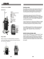
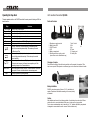
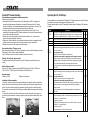
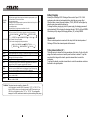
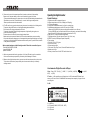
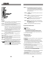
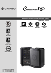
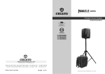
Portable Sound System
Portable
Sound System
OPERATION
MANUAL
GOOD DESIGN
PRODUCT
IT'S VERY WELL
MADE IN TAIWAN
Design Award
HKEIA AWARD
For Outstanding Innovation
and Technology Products
GREEN PRODUCT
It has been RoHS Compliant
CHIAYO ELECTRONICS CO., LTD.
http://www.chiayo.com.tw
OFFICE: 30, LANE 27, SEC.4. JEN-AL ROAD, TAIPEI, TAIWAN / TEL: 886-2-2741-5741
FACTORY: 88, CHUNG HSIAO STREET 2, CHIAYI, TAIWAN. / TEL: 886-5-271-1000
Printed in Taiwan, April 2008
IC︰3563A-CHALLENGER
E-mail: [email protected]
FAX: 886-2-2752-5242
FAX: 886-5-276-7611
12I1150
IC︰3563A-SQ5016
IC︰3563A-SM5016
Challenger 1000 Operation Manual
Maintenance-free Lead Acid battery
Congratulation and thank you for the purchase of this all-in-one portable sound system. To
ensure a trouble-free operation, please read the manual thoroughly to fully understand its
controls and functions.
Guidelines for maintenance-free Batteries:
1. Battery should operate at temperatures between 15°C ~ 50°C. To ensure a longer life span, it
should be kept between 5°C ~ 35°C. For optimum result, 20°C ~ 25°C will be ideal. When
temperature falls 15 degrees below zero, battery will undergo some changes in its chemical
contents and therefore cannot be recharged. Operating the battery at higher temperature will
result in higher capacity but shorter lifespan, whereas lower temperatures operation has a
longer lifespan but less capacity.
2. If the battery is not recharged 72 hrs after it is completely used, it will be permanently damaged.
3. When the battery is being charged, the internal gases will be electrolyzed into water at the
negative charge, maintaining the battery’s storage abilities with no water added. However,
erosion at the charged ends of the battery will cause poor performance.
4. The battery’s cycle lifespan ( no. of charge and discharge cycle ) is determined by the degree at
which power is dissipated., especially the degree of discharged each time it is used and the
recovery charging method. For normal use, the battery can be used for longer hours when less
power is dissipated each time and vice versa. At 25°C, maintenance-free batteries could be
charged 150 ~ 200 times at 100% discharge each time.
5. Decrease in capacity, internal short circuit, deformation in appearance, erosion of charged ends
and decrease in open circuit voltage are symbols indicating battery is approaching the end of its
life cycle.
6. When two batteries are used in parallel connection, the resistance of the cables should be kept
equal.
Followings are various Challenger 1000 variants :
1. Challenger 1000 portable sound system only. ( Fig. 1 )
2. Challenger 1000 with CD / USB Player ( Fig.2 )
3. Challenger 1000 with CD / USB Player & Tape Deck. ( Fig.3 )
4. Challenger 1000 with CD / USB Player & Digital Recorder.( Fig.4 )
All the above versions can be installed with 1 or 2 wireless receiver module(s).
The wireless receiver module can be in either UHF or VHF band and is a PLL synthesized
type with 16 preset frequencies.
Configuration :
All versions of Challenger 1000 series come equipped with the following :
1. AC power cord.
2. 1 or 2 or no wireless receivers.
3. 1 or 2 transmitters, either handheld or bodypack transmitter ( except version with no
module installed ).
Optional accessories :
1. Weather proof dust cover.
2. Tripod stand
3. Companion powered speaker ( Slave speaker ).( Fig. 5 )
4. Companion passive speaker C-SP. ( Fig. 6 )
5. Wired microphone.
Matching transmitters:
Transmitter types
Frequency band
Transmitters
Battery used
Beltpack
Handheld Beltpack
UHF
VHF
SQ-816
SM-216
SM-816 SQ-216
SQ-5016
SM-5016
SQ-916
SM-316
SM-916 SQ-316
Handheld
AAx2
AAx3
9Vx1
AAx2
No. of channel
1
AAx3
9Vx1
16
AAx3
9Vx1
AAx3
9Vx1
Properties of the Lead Acid Battery:
1. Has no memory effect. Can be charged at anytime, even when the recharge indication light is
not on.
2 .Performance and efficiency are affected by changes in the environment, especially temperature
and humidity. (Best operated between 20°C ~ 25°C)
3. Battery discharge naturally according to a certain pattern even not in use. For best performance
and a prolonged lifespan, it should be recharged every month even when not in use.
4. Under normal circumstances, battery could last for about a year.
5. When the battery’s life expires, possible indicators include internal short-circuit, decrease in
capacity, deformation in appearance, erosion of charged ends and decrease in operating
voltage.
User’s Precautions:
1. For first-time use, charge the battery for 10 hrs until it is fully charged.
2. To maintain performance and lifespan, if product has not been used for 3 months after the
initial shipment, please fully charge the battery.
3. Before each use, it’s advisable to charge the battery to its full capacity.
4. The average lifespan of the battery is one year. The user is advised to change the battery after
one year of use.
5. The current consumption is in direct ratio with load current. The more current consumption, the
less the operation time.
6. SMART and FOCUS operate on one 12V/2.7AH battery. ADVENTURE, CHALLENGER, and
VICTORY operate on two 12V/4.5AH batteries.
34
Challenger 1000 ( Master )
( Basic configuration )
5.The audio cable of VHF transmitters also serve as antenna. The length of the cable is cut
according to the specific frequency range. Do not alter the length or mix around the
cable of different transmitters. The use of wrong audio cable will affect the antenna
efficiency of the transmitter!
6.Use only brand new Alkaline batteries. Do not use " general purpose " batteries . When
batteries are weak, replace all the batteries at the same time. Do not mix and use new and
old batteries together.
7.Position the receiver such that it has the least possible obstructions between it and the
transmitter. Line of sight is best !
A. Receiver module 1
SDR-6216m
SDR-6216m
B. Receiver module 2
8.The transmitter and the receiver should be as close as possible but not less than 1m.
9.A receiver cannot receive signals from two or more transmitters simultaneously.
A
B
A
B
10.Turn the transmitter off when it is not in use. Remove the batteries if it is not to be
used for a period of time.
11.Antennas form an integral part of the receiver and must be installed when in operation.
1. MIC IN.
2. LINE-IN VOL.
3. TAPE control
4. BASS
5. TREBLE
5
4
6. MASTER VOL.
7. MIC IN
1
2
6
3
7
4
5
9
8
6
10
8. LINE IN / OUT
9. VOICE PRIORITY
10. ACTIVE OUT ( MASTER OUT )
11
10
12
13 13 1414
12
15 16
7
8
15
AC IN~
90~260 VAC(150W)
47~63Hz 5A Max
11. Battery low LED
11
12. Charging indicator
13. FUSE
9
14. 24~32V DC-IN
16
20
17
18
17
15. AC-IN
16. POWER
19
17. EXT.SP
Fig. 1
33
2
Challenger 1000 ( Master )
(CD / USB Player version )
Operation of wireless microphones
Chiayo Transmitters and Receivers have factory preset to allow immediate use after switch-on.
However, please note that the transmitter Sensitivity function is dependent on application such
as close proximity singing or tripod mouth speech. To avoid over-modulation and distortion,
please check whether the preset sensitivity level is suitable for your particular application. For
close proximity singing purposes, please select the lowest sensitivity level whereas for tripod
mount speech purposes, please select a higher sensitivity level.
SDR-6216m
If you have made changes to the setting, after making proper selection on Transmitter and
Receiver settings the system is ready for operation. However, both antennas of the receiver
must be installed to assure a good reception.
SDR-6216m
A
B
1. LCD Display
B C
D
2. PLAY/PAUSE
E
K
A
H
F G
J
I
3. STOP
First, turn on the receiver by switching the Power/Volume control slowly till its LCD lights up.
The LCD display will show the information last stored.
Switch on the matching transmitter with the correct matching frequency. The LCD display will
show the information last stored.
4. SKIP
5. EJECT
6. CD SELECTOR
7. USB SELECTOR
8. FOLDER SKIP
The LED RF indicator on the receiver front panel will light on to indicate that RF signal has
been received. If this is not the case, please check and verify the frequency setting on both
transmitter and receiver. When transmitter is moving around, the Diversity A/B switch will light
on alternately to indicate the stronger reception on either A or B antenna.
9. IR LED
10. USB INPUT
11. POWER/VOL.
Caution and tips on how to obtain the best results.
1
2
3
4
5
6
7
8
9
10
11
12
13
15 16
CD player
remote control.
2.For PLL-16-frequency agile version, before operation please make sure that the
corresponding receiver MUST have the same frequency group and channel number as
the transmitter.
14
3.Before making any channel change on transmitters, please switch off the power supply. The
synthesized program works in such a way that a change of channel will only take place after
a power off and on action. Otherwise, the previously selected frequency will stay unchanged.
20
AC IN~
90~260 VAC(150W)
47~63Hz 5A Max
17
1.Before inserting the batteries, please make sure that they are inserted according to the
correct polarity.
18
19
4.After making a channel change, please make sure that the corresponding change is made
on the matching receiver as well. To be exact, changes MUST be made at both the
transmitter and receiver.
Fig. 2
3
32
Challenger 1000 ( Master )
(CD / USB Player & Tape Deck Version )
Beltpack Transmitter SM-816(UHF) / SM-216(VHF)
Battery installation
This transmitter uses 3 pieces of " AA " size
batteries (Alkaline battery is recommended ). To
install or remove the batteries, press the release
buttons at the edges of the transmitter to open or
close the cover as illustrated ( Fig.1 ).
SDR-6216m
Fig.1
SDR-6216m
A
Beltclip installation
B
Chargi ng point s
This specially designed detachable beltclip
allows the user to wear the transmitter with
antenna pointing upward or downward as
illustrated. To wear the transmitter with the
transmitter pointing upward, install the belt-clip
as in Fig.2. To wear the transmitter with the
antenna pointing downward, please install the
belt-clip as in Fig.3.
a. Eject key
a
b
Chargi ng point s
Fig.2
b. Counter
c. Variable Speed control
Fig.3
d. Auto reverse indicator
e. Single reverse indicator
c
f. Single side indicator
Channel selection and gain adjust
f e d
Channel selector and gain adjust are hidden
in the designated cover of the front as
illustrated.
To make channel selection and gain adjust,
please press the designated cover and flip it
open as illustrated. Channel selection can be
made by rotating the selector with a small
screw driver.
Gain adjust for Lavalier and Headset
microphones can be done by adjusting the
MT switch, whereas GT switch is for the gain
adjust of electric Guitar and other highimpedance line level inputs.
1
m
2
l
k
3
5
4
i
j
g
h
g. Mode selector
h. Fast forward
i. Forward play
6
7
8
9
10
MT
j. Stop
k. Reverse play
l. Fast reverse
Channel
Selector
11
11
12
13
15 16
GT
m. Rec
14
20
AC IN~
90~260 VAC(150W)
47~63Hz 5A Max
17
18
19
Fig. 3
31
4
Challenger 1000 ( Master )
(CD / USB Player & Digital Recorder version )
Installation of cable restraint
To prevent contact noise caused by constant tension
applied to the connector,,a cable restraint is designed
such that tension is totally reduced when it is
properly used. When the audio cable go through the
cable restraint, it could prevent sweat from going
directly into the electronic board via the connector.
This is another advantage of the cable restraint.
SDR-6100m
SDR-6100m
A
B
2 3
4
5
6 7
8
9
11
1
10
a. POWER
f
Digital Recorder Player
EAR
c
e
d
l
k
POWER
a
g
LINE
REC
b
SD card
p
o
MIC
VOL
L/L+R
h
EQ
A-B
MODE
STOP
F
MIC IN
j
i
VO/M3
DEL.
PLAY
m
C
n
q
R
b. LCD Display
c. EAR
d. USB
VOL
Installation of Lavalier /
Headset microphones or instrument inputs
e. SD Card Slot
f. LINE▲▼
Depending on customer requirements, Lavalier / Headset microphone or instrument
inputs could be connected to the transmitter via the audio input connector. User is free to
choose the various input sources but is advised to take note that connector used must be
compatible to each other. The pin configurations of mini XLR connector are as follow figure.
g. EQ
1
2
3
5
4
h. REPEAT
mini XLR connector
i.
LED INDICATOR
j.
6
7
8
9
10
GT IN
k. REC
l. STOP
m. MODE.
11
12
13
15 16
14
OFF
ON
2
3 4 1
POWER
n. PLAY ll
o. MIC VOL
p. MIC IN
q. VOL
20
AC IN~
90~260 VAC(150W)
47~63Hz 5A Max
17
18
19
ANTENNA
MT IN GND
POWER
SWITCH
PHANTOM POWER
Fig. 4
5
30
Challenger Slave
The Challenger Slave is an active ( powered ) speaker unit with built-in switching
power supply as well as rechargeable batteries, complete with similar charging
circuit as that of the Challenger 1000 Master unit. It is an extended and indispensable member of the Challenger Audio Link system.
Beltpack Transmitter SM-916(UHF) / SM-316(VHF)
Battery installation
Antenna(SM-916)
SM-916/SM-316 use a 9V battery. To
insert the battery, first open the battery
compartment cover by pressing the
cover downward till the door flips open
by itself (see below picture). When
installing the battery, please beware of
correct polarity. To put back the cover of
the battery compartment, one has to
press the cover in upward direction until
it is locked.
Battery status
Indic ator
Power swit ch
Cable
restrain t
Audio in put
Connector
Battery
Compartment
Mik e clip
Capsuale
Fig.1
11. Speaker out (switched)
Channel selection and gain adjust
12. Speaker out
Channel selector and gain adjust are hidden in the designated cover of the front as
illustrated. To make channel selection and gain adjust, please press the designated
cover and flip it open as illustrated.
Channel selection can be made by
rotating the selector with a small
screw driver.
19
20
13. 24-32V DC input
21
14. Fuse
15. Battery low indicator
11
13
12
15 16
18
14
16. Battery status indicator
17. AC input
18. Charging indicator
19. Slave IN
Gain adjust for Lavalier and Headset
microphones can be done by adjusting
the MT switch, whereas GT switch is
for the gain adjust of electric Guitar
and other high- impedance line level
inputs.
20. Slave OUT
21. Slave VOL.
MT
Channel
Selector
17
GT
29
Fig.5
6
Challenger Speaker ( C-SP )
The Challenger Speaker is a passive companion speaker for the Challenger 1000 series.
It is for connection to the switched or unswitched speaker outs of the Challenger 1000
( Master ) or the Challenger Slave units. 22. Speaker IN
23. Speaker OUT
22
23
Fig. 6
7
28
Operating procedures
UHF Beltpack Transmitter SM-5016
Parts & Functions
7
8
9
10
11
Antenna
Battery weak / audio mute indicator
Audio mute switch
Mini-XLR connector
Power ON / OFF switch
LCD display
Charging port
Cover release button
Charging contacts
Lavalier microphone
Mic clip
12
13
1516
14
12
13
14
15
16
SET
UP
DOWN
GT
MT
Battery installation
SM-5016 uses 2 pieces of " AA " size batteries (Alkaline battery is recommended ). To
install or remove the batteries, press the release buttons at the edges of the transmitter to
open or close the cover as illustrated below.
27
After unpacking the unit for the first time, please charge the unit for about 4-5 hours
before any operation. This is absolutely necessary as the built-in rechargeable
battery might have been discharged naturally due to long shipment and storage
time, even though it has been fully charged in the factory prior to shipment.
To charge the battery, just plug in the AC cord into the AC IN of the unit and
charging will start automatically. During the charging process, the charging indicator
LED will flash GREEN. When GREEN LED stays glow permanently, battery is then
fully charged and normal operation could now be started. While charging, the unit
could also be operated simultaneously.
To operate this portable sound unit, switch on the main POWER switch, the GREEN
LED above it will glow. However, if the RED LED also glows at the same time, it
means the battery is getting weak and a recharge of the battery is necessary.
The main POWER switch does NOT switch on the Wireless receiver module and
Tape deck/ CD player/ Digital Recorder as each of them has dedicated Power /
Volume control switch. To operate each of them, you must switch them on
accordingly.
Operation of wireless microphone system
The receiver installed on Challenger-1000 is a PLL-synthesized type with 16 preset
frequencies for selection. It has an UP, DOWN buttons and 2 * 7-segment LED
indicator. To operate the wireless system, just switch on the power / volume switch
on the module front panel and the matching transmitter. Please ensure that the
channel setting on both the wireless microphone and receiver module are the same
before operation.
8
16-Channel wireless microphone system ( UHF )
To operate, switch on the PWR / VOL switch, the 2*7-segment LED indicator will light
up and the last used channel in memory will be displayed. Channel setting can be
changed by Pressing either the ▲/▼button.
Switch on the corresponding transmitter. RF or Diversity indicator A or B will light up
when both are in the same channel setting. The movement of the transmitter causes
diversity indicator A or B to light up alternately.
UHF SDR-6216m
TRUE DIVERSITY RECEIVER
PWR/Min
Max
Handheld Transmitter SQ-816(UHF) / SQ-216(VHF)
Parts & functions
When both transmitter and receiver are on, speak
into the microphone and rotate the dedicated
volume control and master volume control,
amplified sound could be heard from the
speaker. 1. Capsule with metal grille
2. Battery normal indicator (Green)
When interference occurs, turning the SQ switch in clockwise direction will make it diminish
3. Battery low indicator (Red)
or disappear completely. 4. Power on/off switch
However if interference noise persists even though SQ is at max. position, it means this
5. Channel switch
channel is useless at this location. Press ▲/▼or SCAN to search for the next clean channel.
6. Charging port
The corresponding transmitter channel setting must also be changed accordingly to match the
receiver selection. The battery indicator LED on receiver panel serves as remote transmitter battery status
monitor. Lighting up of this monitor LED indicates transmitter battery is weak ! Battery installation
16-Channel wireless microphone system( VHF ) To operate, switch on the PWR / VOL switch, POWER LED will light up. Channel setting can
be changed by the rotary switch. Switch on the corresponding transmitter. RF or Diversity indicator A or B will light up when
both are in the same channel setting. The movement of the transmitter causes diversity
indicator A or B to light up alternately. SDR-216M
VHF PLL TRUE DIVERSITY RECEIVER
SQ-816/SQ-216 transmitter requires 3 pieces of " AA " size battery to operate.
Please insert the batteries according to the correct polarity as indicated. To open the
battery compartment, press and slide down the cover until it clicks and locks. Further
sliding movement will remove the cover.
When both transmitter and receiver are on, speak
into the microphone and rotate the dedicated
volume control and master volume control,
amplified sound could be heard from the
speaker. When interference occurs, turning the SQ switch in clockwise direction will make it diminish or
disappear completely.
However if interference noise persists even though SQ is at max. position, then use rotary
switch to change it to another channel and press the TEST button. When neither RF A nor B
indicator light up, then this particular channel is considered clean. The corresponding
transmitter channel setting must also be changed accordingly to match the receiver selection.
9
26
Changing capsule
Operating the dynamic wired microphone.
This microphone has a modular design. To change or replace a capsule, Open the grill
to pull out and plug in the capsule as shown in the following figure.
To use a cable microphone, simply plug it into any MIC IN socket. The unique
Neutrik combo socket accepts both phone and Cannon jack. Rotate the dedicated
volume control knob and master volume control, amplified sound could be heard
from the speaker when voice is spoken into the cable microphone.
Operation of system with CD / USB Player.
This operation is valid for version of Challenger 1000 with built-in " CD / USB Player"
To operate, push the Power/Vol button to turn on the player. The LCD panel on the
player will be lighted up and normal operation is ready. To insert a CD, just push it
into the CD slot and the mechanism will suck it in automatically.
Rotate the volume control knob to adjust the volume of the player. For Bass and
Treble setting, adjust the individual Bass and Treble controls.
For more details, please refer to the instruction on " CD / USB Player" controls and
functions.
Operation of system with Digital Recorder.
Operating instructions
This operation is valid for version of Challenger 1000 with built-in " Digital Recorder "
1. Before operation, please check and make sure that transmitter & receiver are of
matching frequency or frequency group.
2 .To switch on the microphone, put the switch to "ON" position. The green LED
indicator will light on to indicate that battery is fresh. When RED LED light on, it
indicates that battery is weak, thus a replacement is necessary.
3. For best result, alkaline battery is recommended. Please remove the battery if the
transmitter is not to be used for a longer period.
4.When necessary, mic capsule could be replaced by pulling out and plugging in the
new one, either dynamic or condenser for SQ-916. To operate, first turn on the Master power switch and then press the designated
power button of this module. The LCD display will be lighted up and Volume setting
can be done by rotating the knob. For Bass and Treble setting, adjust the designated
controls respectively.
For more details, please refer to the instruction of " Digital Recorder " controls and
functions.
Operation of system with Tape Deck.
This operation is valid for version of Challenger 1000 with built-in " Tape Deck ".
Rotate the volume control knob of the TAPE / CD control to adjust the volume of the
Tape deck. For Bass and Treble setting, adjust the designated controls respectively.
For more details, please refer to the instruction of " Tape Deck " Controls and
functions.
25
10
Handheld Transmitter SQ-916(UHF) / SQ-316(VHF)
Audio Link Operation
Schematic diagram
Parts & functions
MASTER
SLAVE
1. Capsule with metal grille
2. Battery indicator
3. Sensitivity switch
4. Power on/off switch
5. Battery cover
7. Color cap
SLAVE
Audio Link Connection
Plan
SLAVE
Battery installation
SLAVE
SLAVE
SLAVE
SQ-916/SQ-316 use a 9V battery for power. To change or replace the battery,
please remove the color cap first, then press the bottom of battery compartment to
release the cover as shown below.
Pre
ss
When a Master unit is connected to one or several SLAVE units as follow, we called it
an Audio Link Operation.
The Challenger 1000 could be operated as MASTER only. The Challenger Slave can
only be operated as SLAVE. Sensitivity switch
In order to operate Audio Link, you must have a Challenger 1000 unit that operates
as a MASTER. Only one unit is allowed to act as MASTER and the other(s) MUST
This microphone has a sensitivity switch. For close mouth singing or normal speech,
operate as SLAVE(s). A MASTER unit is capable of connecting up to about 20
please put the switch to L ( Low ) position. For tripod-mount speech, please put the
SLAVE units. switch to N ( Normal ) position.
To operate Audio Link, connect the Active Out ( 10 ) of the MASTER to the Audio
Link IN ( 19 ) of the 1st SLAVE unit. The Out ( 20 ) of this SLAVE should be
connected to the IN jack ( 19 ) of the 2nd SLAVE unit. Similar connection shall
continue as such for the following SLAVE units. Volume Control ( 6 ) for MASTER or ( 21 ) for SLAVE. When used on the MASTER, it controls the MASTER as well as all the SLAVE units. When used on the SLAVE unit, it only controls that particular SLAVE unit volume. Maximum number of SLAVE units to be connected with a MASTER is about 20. 11
L
N
L
Low Sensitivity
Normal Sensitivity
24
N
Voice Priority ( Ducking ) operation
Voice Priority ( Voice overrides Music ) operation is only necessary when Tape or CD
is playing. When the Voice Priority switch ( 9 ) is put to ON position, the ducking
function will be activated. While the music is playing, a voice input from either a
Wired or Wireless Microphone will temporary turn down the volume of the
background music and voice could be heard clearly. Background music will return to
its original setting when no audio input is entering the microphone for a certain time.
However, if the microphone is not switch off, the reentering of music into the
microphone will also activate the voice priority function. So, voice priority is best
operated using microphones with on / off switch.
Mechanical Parts
All the Challenger 1000 ( Master ), Challenger Slave and the Challenger companion
speaker ( C-SP ) enclosures have the identical mechanical parts as follow :
Three-stage Trolley ( 24 )
Trolley release button ( 25 )
Handle ( 26 )
Wheels ( 27 )
Tripod mount bracket ( 28 )
24
25
26
27
28
Remark : Please be advised that the trolley and wheels are designed for moving
around on smooth surface and short distance only. It is NOT meant or built for heavy
duty long distance transportation or on rough surfaces. Please DO NOT use the
trolley as handle for going up and down the staircase. For going up and down the
staircase, please use the Handle ( 26 ). 23
12
Operating the Tape Deck
UHF Handheld Transmitter SQ-5016
To begin operation switch on the TAPE Power after the main power of challenger 1000 has
been turned on.
Parts and functions
Keys
Speed Control
Eject
Press this key for fast forward .
Press this key for play in forward direction.
Press this key to stop the tape.
Press this key for play in reverse direction.
Press this key for fast reverse.
Press this key together with FP or RP key for recording.
This key is pressed to select one of the following three modes.
Active in Forward nor Reverse direction, the cassette tape will
play to the end and stop automatically. This mode may be used
for Record and Play.
The cassette tape will play to the end, stop, reverse direction to
the end of the second side and stop. This mode may be used for
Record and Play.
This mode provides continuous " Play " operation. It is not operable
in Record mode, however, it will record one complete cycle if the
recording is begun in the Forward direction.
Normal tape speed at center position. Clockwise direction increases
tape speed. Counter-clockwise direction reduces tape speed.
This key is pressed for ejecting the tape.
5016
FF Fast Forward
FP Forward Play
Stop
RP Reverse Play
FR Fast Reverse
Record
Mode selector
Functions
7. Lock / Unlock
8. Set
9. Up
10. Down
11. Charging port
12. Name plate
1. Microphone capsule module
2. Battery status LED
3. ON/OFF switch
4. LCD
5. Battery compartment
6. Rotating protective cap for controls
(also serves as color identification cap)
Changing of capsule
First unscrew the metal grill from the housing and take out the capsule to be replaced. Then
insert a new capsule. Either dynamic or condenser type can be chosen from location to location.
Battery installation
SQ-5016 microphone requires 2 pieces of " AA " size batteries to
operate. Please insert the batteries according to the correct polarity
as indicated.
Caution
Many batteries are known to have leakage problem of conductive and corrosive liquid. Please
observe the rule to remove the batteries if they are not to be used for a longer period.
Due to various unstandardized sizes ( diameters ) of " AA " batteries, this battery compartment
is designed to accommodate the most common Alkaline batteries only.
13
22
Operating the CD / USB Player
Simple DIY Trouble-shooting :
No sound when one speaks to the wireless microphone
Please verify the followings:
1.Main power switch of the system should be ON. When power on LED not lighted up, it
means that the batteries are either weak or not charged. Please plug in the AC cable to
charge the batteries. The rechargeable batteries have a life span of about 2 years. If they
have reached their life expectancy, please change them to a fresh pair.
2.The power switch of the corresponding receiver module should be put to ON. This is
indicated by the lighted power LED. When two wireless mics are used, both power switches
of the receiver modules must be ON.
3.Wireless mic should be switched ON and verify that the battery is o.k. ( please refer to
wireless microphone operating instruction ).
4.Please verify that the frequency on the wireless microphone and the corresponding built-in
wireless receiver module are exactly of the same frequency group and channel.
5.Master volume control of the system should be turned on.
No sound when Tape / CD player is used.
Main power switch should be ON. When no light appears, it means that the batteries are weak.
Please plug in the AC cable to charge the batteries.
Tape / CD volume control is turned on but Master volume control not on.
Ducking ( Voice Priority ) does not work
Please ensure that the Voice Priority switch is put to ON position to activate the ducking
circuitry.
Audio Link does not work
Only one OUT cable is connected from the MASTER to the IN jack of the 1st SLAVE unit.
st
The OUT of the 1 SLAVE goes to the IN of the next SLAVE and so on.
No power supply
1.Battery is faulty
2.Battery is not charged.
Installation of Receiver module
To install the receiver module, first remove the blank panel covering the module compartment,
position the module such that it fits exactly into the guide rail in the module compartment and
push it to the end so that the gold finger connection plug firmly fits into the socket provided.
To secure the receiver module to the Challenger rear panel, tighten the receiver panel with two
screws.
To remove the receiver module, first unscrew the two screws on the module front panel, pull
up the trolley, follow instruction as shown in the picture and push out the module with a screw
driver.
2
1
UHF
Front remotable is an unique feature of Challenger 1000. User can easily control this CD player
by clicking its remote from both front and rear Challenger 1000.
To begin operation switch on the CD Power after the main power of Challenger 1000 has been
turned on.
Keys
Functions
UHF
21
Panel Remote
When this key is pushed during CD stop, play will start after track search.
When this key is pushed during CD is playing, then it is changed to pause.
When this key is pushed during CD is pausing, then it is changed to play.
When CD is not stop, if this key is pushed then CD will stop.
STOP
When press this key will change to cd-mp3 mode.
CD
When press this key will changed to USB mode.
USB
In stop mode:
Change the starting play track(file) during stop mode, cyclic to the first track,
if it is in the last track.
SKIP+
In program entry mode:
UP/CUE
Change to the next track(file) for program select .
In play mode, pause mode, program play mode, random play mode:
Single pressed, skip the playing track(file) to next track(file) for normal
play/pause mode, to next program index track(file) for program play/pause
mode, to next random track(file) for random play /pause mode.
Continue pressed , fast forward during play/pause when pressed more
than 0.7sec.
In stop mode:
Change the starting play track (file) during stop mode, cyclic to the last track,
if it is in the first track.
SKIPDONW/REV In program Entry mode:
Change to the previous track (file) for program select.
In play mode, pause mode, program play mode:
Single pressed, skip the playing track (file) to precious track(file) for normal
play/pause mode, to previous program index track(file) for program
play/pause mode.
Continue pressed, fast reverse during play/pause when pressed more
than 0.7sec.
FOLDER-UP In stop mode:
Skip the starting play folder to next folder during stop mode, cyclic to the
first folder if it is in the last folder.
In program entry mode:
Change the file for program select to next folder's first file, cyclic to the
first folder if it is in the last folder.
In normal play mode:
Skip the playing file to the next folder's first file.
PLAY/
PAUSE
14
FOLDERDOWN
Battery Charging
In stop mode:
Skip the starting play folder to previous folder during stop mode, cyclic
to the last folder if it is in the first folder.
In program entry mode:
Change the file for program select to previous folder's first file, cyclic to
the last folder if it is in the first folder.
In normal play mode:
Skip the playing file to the previous folder's first file.
Internally, the Challenger 1000 / Challenger Slave contain 2 pcs of 12V / 4.5AH
maintenance-free lead acid rechargeable battery, which has no memory effect.
When the battery is weak, the power indicator ( 11&15 ) RED LED will be lighted up
when the main power switch is switched on.
To charge the battery, simply plug in the AC power supply, the charging process will
start automatically. While charging, the charging indicator ( 12&20 ) will flash GREEN..
When battery is fully charged, the charging indicator ( 20 ) will stay GREEN.
In mp3 mode and in USB mode .
If this key is pushed, PLAY mode is changed cyclically shown below.
PLAY ALL RANDOM
REPEAT TRACK
REPEAT FOLDER
PLAY MODE
REPEAT ALL
RANDOM REPEAT
IN CD mo de If this key is pushed,
PLAY mo de is changed cyclically shown below
PLAY ALL RANDOM
REPEAT ALL
EJECT
PROG
MUTE
POWER
ESP
FIND
0~10;
VOL.VOL.+
PLAY ALL
Speaker out
When an external speaker is connected to this output, both the internal speaker of
Challenger 1000 and the external speaker will have sound.
REPEAT TRACK
RANDOM REPEAT
PLAY ALL.
When this key is pushed, door is moved out.
Set to programming mode.
When programming mode, [stop] key is pushed then program is all cleared.
When this key is pushed during CD is playing, the set will mute the output.
Push again, will recovery the output .
Power SW o f the set .
In CDDA mode, Press"ESP" key , The ESP display lighted and the set is
in electronic anti-shock state. The electronic anti-shock time is about 40
seconds. Press "ESP" key again, cancel the ESP function.
In MP3 mode : Press this key once FILE search mode changed .
Press this key twice ALBUM search mode changed .If press this key long
time once track is displayed .press twice ID3 TAG is displayed.
You can use these keys to select the track you want directly.
When this key is pushed , the volume will decrease by 1dB per step ,
the min. volume is 0dB.
When this key is pushed, the volume will increase by 1dB per step ,
the max. volume is 30dB.
Trolley release button ( 27 )
option
This button serves to release the locking mechanism of the trolley. To pull out the first
stage of the handle, one does not need to press the button to release it. To pull the
second and third stages of the handle, press the release button to unlock the
mechanism.
To put back the handle, press the release button to unlock the mechanism and return
the handle to its original position.
ENCODE
ENCODE
Caution: This player does not accept 8-cm diameter CD.
User is advised to have the USB 2.0 formatted in " FAT " or " FAT 32 ". The
built-in USB 2.0 player can not be able to read the MP3 files stored in your
USB if it is not formatted by either " FAT " or " FAT-32 ". To avoid possible
damage to the USB, remember to detach it only after switching off the player.
15
20
9. Please use the one with cooperate specification (marks on the back of the machine).
Please turn off the power when you do not use the machine for a period of times.
* To keep stable data transmission, please do not twist the USB cable during data transmission.
* Please do not press the LCD monitor heavily, or touch it with finger or sharp articles.
* Please prevent water leak into the machine.
10 . The SD card is a very precise electronic part, please use it according to the following notice:
*To prevent taking the SD card out of the machine during data transmission.
*Do not bend, strike, drop or take apart the SD card.
*To prevent to place the SD card in a high temperature, high humidity, dusty place, or a
place full with static electricity.
*Please make sure the SD card you are using has been format.
*Make sure the write protection switch of the SD card is released when you are recording .
*Our product will process large amount of messages during recording and playing, we strongly
suggest you to use high speed SD card as extension memory card, to prevent noise, data lose
or any transmission problem.
* We have tested and approval the following brands of SD card for our machine, they are:
Toshiba SD-M51225R2W 512MB
Apacer SD 120X 1GB
Apacer SD 256MB
Operating the Digital Recorder
Product Features :
1.Digital record to MP3 compression format
2.Highest sample rate at 44.1KHz, 128Kbps (as CD quality).
3.1 - 99 recording tracks.
4.Equiped with 128MB flash memory for 60 min. recording time.
5.Available expanded memory socket of SD card. Up to 512MB
( When using 512 MB SD card, the recording time is available for over 8 hours.)
( If using 1G MB SD card, it will be divided into 99 recording tracks, each track with recording
time less than 9:59:59 will be able to display time function on LCD.)
6.USB port to PC for easy download or duplication.
7.EQ mode selection (5 modes: Normal, Classic, Pop, Rock, Jazz)
8.REPEAT function (A-B Repeat, Repeat, Repeat All)..
9.Time counting
10.Two MIC-IN (L/L+R, R) jacks.
11.Line-in control key.
12.Stereo earphone jack.
13.Tack select, Play, Stop, Pause, Forward & Rewind control keys.
14.Mode control keys.
15.Rotary Volume Control for MIC REC. and Volume Level.
11. We do not guarantee the function, operation, or life of any SD card is used in our machine.
We do not also take any responsibility of indemnity for the damage of SD cards.
12. Same as other digital stock products, user must save the inner documents from time to time.
This product will not take any responsibility due to documents lost directly or indirectly
damage caused.
Usual manual of Digital Recorder & Player
1.Key---Power ,REC ,PLAY(ll) , ¦ ,MODE ,? ,? (/LINE IN) , A-B(/EQ) ,
MP3) , >>(/DEL.)
(
), <<(/VOC,/
2. Tracks----1~99 tracks. May store 99 tracks both in VOC mode and MP3 Mode, flash
memory or SD card. Built-in 128MB NAND flash memory has a capacity of approx. 60 min.
recording time.
3.LCD:
3-1
3-2
3-3
3-4
19
MODE key
EQ select(CLASSIC, POP, ROCK, JAZZ)
VOC mode
MP3 mode
16
5. MODE key------ Push the MODE key with another key for special function selection. The
LCD will show "MODE" when push MODE key, you shall push another
function key to perform the function. If you does not push another function
key within 5 seconds, the machine will back to idle mode. Following is the
detail of special function keys.
5-1 MODE key + ? (/LINE IN) key:LCD will show "LINE IN", and select line in audio source
as recording source.
5-2 MODE key + A-B(/EQ) key :For EQ select function. EQ sequence is Normal?Classic?
Pop?Rock?Jazz. (Normal EQ will not be shown on LCD)
5-3 MODE key +
(/VOC,/MP3) key: To select VOC mode (Record from microphone or
LINE IN source) or MP3 mode (Download *.mp3 files from PC).
4.Key control
4-1 Power key
4-2 Upper key:Upper key for track selection. Track number will move quickly when push still
for two seconds (this function will not work in MP3 mode).
4-3 Down key:Down key for track selection. Track number will move quickly when push still
for two seconds (this function will not work in MP3 mode).
4-4 REC key:Record key. Select track no. in VOC mode in advance, push REC key to record,
then push ? key to stop record. If the track you want to record is occupied, the
LCD will show " ?? " you must delete the content of the track before you record.
When the memory is with 30 seconds left, the LCD will start to count 30,29,28,
27.....6,5,4,3,2,1,0 You can use microphones LINE IN audio source or both
mixed source for recording source.
4-5 Play/ ll key: Play key. Select the track no. you want to play, then push PLAY key to play.
Push PLAY key during playing will pause play, then push PLAY key again to
start playing. Push STOP Key to stop play.
4-6 ? key:STOP key. Push the key to stop all the motions, ex.: recording, playing, track
selection..?
4-7
key(Forward):Forward key. The playing will move forward when press the key, back
to normal speed when release the key.
4-8
key(Rewind):Rewind Key. The playing will move rewind when press the key, back to
normal speed when release the key.
4-9 A-B repeat key:During playing, push this key to indicate any point as start point (A point)
and finish point(B point) on a track, the machine will repeat from A to B point
until you push the key again to release the function and continue to play.
4-10
&
Repeat key:In MP3 mode during playing, push REPEAT key once to"epeat the
track" the LCD will show
, and push REPEAT key twice to"repeat all the
track" , the LCD will show
. Push the key at the third time to release repeat
function. The "Repeat all " function can not be used in VOC mode.
5-4 MODE key +
(/Del.) key : When push these two keys, the LCD will show DEL,you
must push
(/Del.) key again to delete the track. The LCD will show"DEL"
until the delete process is finished.
5-5 MODE key + ¦ key : Change flash and SD card under PLAY and Idle modes.
6. The machine offers extended connectors:
6-1 EAR :for earphone
6-2
:USB connector to PC
6-3 SD card:for extended SD memory card,up to 512MB
(When use 512 MB SD card, the recording time is available for over 8 hours)
( If use 1GMB SD card, it will be divided into 99 tracks recording, each track of
recording time no more than 9:59:59 will be able to display time function on LCD)
6-4 MIC IN:connect to two microphones
7. ROTARY VOLUME CONTROL
7.1 MIC REC. Rotary Volume Control
7.2 Level Rotary Volume Control.
8. USB CONNECTION : You can easily copy MP3 files from computer to the machine through
USB connection.
A. Install Hardware: Connect the machine and your computer with a USB cable. You
computer will recognize a new removable storage device automatically. You can add,
delete, copy, and preview files. (If the operation system of your computer is Window 98 or
below, you must install USB driver for first use. The USB driver is included.)
B. Store new files to VOC mode: MP3 files on the computer can be stored to VOC mode.
However, the file names must be renamed as following format:
B-1:If you want to store the file to flash memory in VOC mode, you must rename it asM_INT
_XX.MP3 (XX stands for track location)
B-2:If you want to store the file to SD card in VOC mode, you must rename it as M_EXT_XX.
MP3 (XX stands for track location) File format must be MP3 to work.
C. Store new files to MP3 mode: *mp3 or *wma files on the computer can be stored to MP3
mode, no need to rename the file, it will store to MP3 mode automatically.
E: After completing all operations on computer, please detect the USB connection then to
operate the machine.
* * * NOTICE:Please read the following notice before you use our DIGI- REC Series .
17
18