1
SDC-10
SDC-10
Preface
ABOUT THIS MANUAL
This manual is designed for use with the Wolf Cinema SDC-10 Home Cinema Projector. Information in this document has
been carefully checked for accuracy; however, no guarantee is given to the correctness of the contents. The information and
specifications in this document are subject to change without notice.
COPYRIGHT
© Copyright 2012 Wolf Cinema.
This document contains proprietary information protected by copyright. All rights are reserved. No part of this manual may be
reproduced by any mechanical, electronic or other means, in any form, without prior written permission of the manufacturer.
TRADEMARKS
All trademarks and registered trademarks are the property of their respective owners.
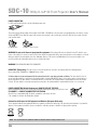
The lighting flash with arrow head within an equilateral triangle is intended to alert the user to the presence
of “dangerous voltage” within the product's enclosure that may be of sufficient magnitude to constitute a risk
of electric shock to persons.
The exclamation point within an equilateral triangle is intended to alert the user to the presence of important
operating and maintenance (servicing) instructions in the literature accompanying the appliance.
WARNING: TO REDUCE THE RISK OF FIRE OR ELECTRIC SHOCK, DO NOT EXPOSE THIS APPLIANCE TO RAIN OR MOISTURE.
DANGEROUS HIGH VOLTAGES ARE PRESENT INSIDE THE ENCLOSURE. DO NOT OPEN THE CABINET. REFER SERVICING TO
QUALIFIED PERSONNAL ONLY.
1
SDC-10 1080p D-ILA 3D Front Projector User’s Manual
®
Notices
WARNING! To meet FCC requirements, a shielded power cord is recommended in order to prevent interference. It
is essential that only the supplied power cord is to be used. Use only shielded cables to connect I/O devices to this
equipment. You are cautioned that changes or modifications not approved by the party responsible for compliance
could void your authority to operate the equipment.
WARNING! High-brightness light source. Do not stare into the beam of light, or view directly. Be especially careful
and ensure that children do not stare directly into the beam of light.
WARNING! To reduce the risk of fire or electric shock, do not expose this product to rain or moisture.
CAUTION! For minimal servicing and to maintain high image quality, we recommend that you use the projector in
an environment that is smoke and dust free. When used in areas where there is a lot of smoke or dust, the filter
and lens should be cleaned often to lengthen the service life of the projector.
WARNING! IC chips or other technologies in the product include confidential and/or trade secret property belonging
to either Wolf Cinema or the Victor Company of Japan (JVC). Therefore you may not copy, modify, adapt, translate,
distribute, reverse engineer, reverse assemble or decompile the contents thereof.
WARNING! The ventilation slots and objects next to them may get extremely hot during operation. Do not touch
these areas until they have sufficiently cooled down.
DISPOSAL Do not use household or municipal waste collection services for disposal of electrical and
electronic equipment. EU countries require the use of separate recycling collection services.
2
SDC-10
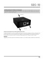
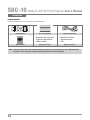
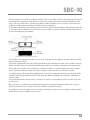
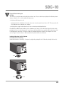
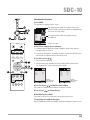
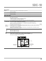
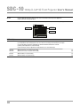
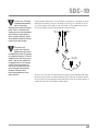
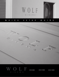
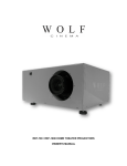
CAUTION REGARDING THE EXHAUST OF THE PROJECTOR
Do not place the projector in a space that is poorly ventilated or confined. Allow at least 20 in. (50 cm) clearance from walls
and have free air flow around the projector.
➟
Air Intake Vent
➟
➟
Exhaust Vents
Before using the projector, please read this operation guide carefully.
To facilitate reporting the loss or theft of your Wolf Cinema components, record the Serial Number located (a) on the bottom of the
projector and (b) on the rear of the outboard ProScaler, if applicable; retain this information. Before recycling the packaging, be
sure that you have checked the contents of the carton(s) thoroughly against the list of “Package Contents” on page 6.
WARRANTY
This product comes with an original owner's Manufacturer's Warranty. See the separate Statement of Warranty for complete details.
3
SDC-10 1080p D-ILA 3D Front Projector User’s Manual
®
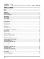
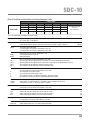
Contents
Preface.................................................................................................................................................................................1
Notices .................................................................................................................................................................................2
Introduction ........................................................................................................................................................................6
Package Contents.................................................................................................................................................................6
Features and Specifications ..................................................................................................................................................7
Getting Started ...................................................................................................................................................................8
Safety Precautions................................................................................................................................................................8
Power Connection...............................................................................................................................................................12
Accessories/Optional Accessories .......................................................................................................................................13
Controls & Features..........................................................................................................................................................14
Operation Panel ..................................................................................................................................................................15
Status Indicator Lights ........................................................................................................................................................16
Main Input Terminal ............................................................................................................................................................18
Remote Control.................................................................................................................................................................19
Remote Control Features ....................................................................................................................................................19
Inserting Batteries into the Remote Control .........................................................................................................................19
About Installation .............................................................................................................................................................20
Projector Mounting .............................................................................................................................................................23
Mounting Precautions .........................................................................................................................................................23
Screen Size and Projection Distance ...................................................................................................................................24
Effective Range of IR Remote Control..................................................................................................................................24
Making the Connection ....................................................................................................................................................25
Types of Possible Input Signals (PC Compatible)..................................................................................................................25
Connecting Video Sources to the Projector ..........................................................................................................................26
Connecting via HDMI Cable.................................................................................................................................................27
Connecting via Component Video Cable ..............................................................................................................................28
Connecting via RGB Video Cable .........................................................................................................................................28
Connecting a 3D Emitter .....................................................................................................................................................29
Connecting the Trigger Cable ..............................................................................................................................................30
Connecting the RS-232C Control Cable...............................................................................................................................30
Connecting LAN Terminal....................................................................................................................................................31
Connecting an External Infrared Sensor ..............................................................................................................................31
Connecting the AC Power Cord (provided) ...........................................................................................................................32
Basic Operation ................................................................................................................................................................33
Basic Operation Procedures................................................................................................................................................33
Sizing, Masking and Keystone.............................................................................................................................................35
4
SDC-10
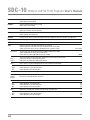
Menu .................................................................................................................................................................................38
Menu Settings and Adjustments..........................................................................................................................................38
Menu Button.......................................................................................................................................................................44
Menu Operation Procedures................................................................................................................................................45
Menu Item Descriptions ......................................................................................................................................................46
Operation Guide ................................................................................................................................................................59
Operation Guide Glossary....................................................................................................................................................59
Replacing the Lamp..........................................................................................................................................................63
Lamp Replacement Procedure ............................................................................................................................................63
Resetting Lamp Time ..........................................................................................................................................................65
Filter ..................................................................................................................................................................................67
Cleaning and Replacing Filters ............................................................................................................................................67
Troubleshooting................................................................................................................................................................68
Error Messages.................................................................................................................................................................70
RS-232C Interface ............................................................................................................................................................71
RS-232C Specifications ......................................................................................................................................................71
TCP/IP-Connection..............................................................................................................................................................71
Command Format...............................................................................................................................................................72
RS-232C Communication Examples....................................................................................................................................74
Copyright and Caution......................................................................................................................................................75
Specifications ...................................................................................................................................................................76
Dimensions ........................................................................................................................................................................77
5
SDC-10 1080p D-ILA 3D Front Projector User’s Manual
®
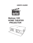
Introduction
System IR Remote
PIC.
ADJ.
COLOR
P.FILE
COLOR
TEMP
GAMMA
3D
INFO
USER
C.M.D.
STAGE
NATURAL
BACK
ANIME
CINEMA
PICTURE MODE
MENU
FILM
LIGHT
LENS AP.
LENS
MEMORY
LENS.
CONTROL
HIDE
3D
SETTING
3D
FORMAT
COMP.
HDMI 2
HDMI 1
ON
INPUT
STAND BY
ANAMO.
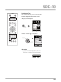
Package Contents
Open the package and ensure that you have the following items:
Two “AA” size batteries
• Stereoscopic (3D) emitter and
3D glasses, adult and child
editions available
Owner’s Manual
Optional accessories:
Power cord (By country)
• Wolf Cinema ProScaler
• Replacement lamp
• Filter
Optional accessories:
Note: • Some of the cables may not be included depending on the region. Please check with your nearest Authorized Dealer.
• If anything is missing or appears damaged, contact your Wolf Cinema dealer immediately.
6
SDC-10
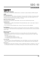
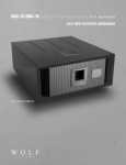
Thank you for purchasing the Wolf Cinema SDC-10 – a next-generation stereoscopic (3D) home cinema projector.
Suitable for home theater screens up to 12’ in width, the SDC-10 is built around a three-chip, D-ILA® [Direct Drive Image Light
Amplifier] light engine for ultra-high-fidelity 1080p viewing. D-ILA is a LCoS [Liquid Crystal on Silicon] technology originated by the
Victor Company of Japan [JVC], which produces stunning film-like imaging with deep contrast level performance and natural color
renditions. The system is complemented by custom Wolf Cinema video processing algorithms with advanced optics that deliver
razor-sharp images from today’s most demanding HD sources.
New for this year is the integrated Wolf Cinema VariScope™ lens memory system. This unique technique enables quick access
to the three most common video aspect ratios – 1.78:1, 1.85:1 and 2.35:1 – all without the need of an external anamorphic lens.
This feature provides for full 2:35:1 CinemaScope™ widescreen viewing without those unwanted top/bottom “black bars” on
appropriate cinema screens. And for true film aficionados everywhere, two precision VariScope™ FX fixed anamorphic lens
assemblies are available – especially useful when taking advantage of the full installation range of the primary system optics.
Optimized Wolf Cinema 3D shutter glasses and 3D signal emitter remain important accessory options, available whenever one
desires the finest in personal 3D viewing experiences.
Like all Wolf projectors, the SDC-10 is designed with a highly-efficient thermal chassis for extended projector and lamp life. Multiple
whisper fans help keep the light engine at optimum running temperatures by routing air in a rear-to-front design, facilitating a wide
range of placement options for the custom installer. Last but not least, SDC-10 projector ceiling mount kits are also available for
ease of installation.
The SDC-10 is delivered in an elegant high-gloss black cabinet, and provides for complete system IR remote control, LAN and
RS-232 control capabilities. The SDC-10 boasts a dual set of HDMI 1.4 inputs and one set of component video inputs.
We hope you enjoy your Wolf Cinema home theater experience.
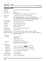
SDC-10 FEATURES AND SPECIFICATIONS:
• D-ILA® three-chip, 1920 x 1080 [1080p] home cinema projector
• Onboard VariScope™ lens memory system [three custom presets] for 1.78, 1.85 and 2.35:1 film aspect ratio viewing
• Advanced real time 2D-to-3D viewing modes
• 220W lamp, 1300 ANSI, ~70,000:1 CR performance
• Ultra-high contrast chipset with next-gen home cinema iris
• Hand calibrated for both 2D and 3D operation
• 6 custom preset viewing modes, 3 color space memories and screen surface compensation driver
• Extended range primary lens: 1.45:1 to 2.78:1 TD
• Inputs: HDMI 1.4a (2), Component (1)
• IR Remote Control included plus LAN, RS-232 system control capabilities
• Two optional VariScope FX™ fixed anamorphic lens assemblies
• Elegant gloss black cabinet with optimized thermal design for extended projector and lamp life
• Optional 3D starter pack includes 3D signal emitter and two pair of active glasses; additional glasses available
• Optional WC-PM-M ceiling mount kit
*Note: Post calibration light output and contrast performance will vary based on screen size, screen gain, ambient light
conditions and more.
7
SDC-10 1080p D-ILA 3D Front Projector User’s Manual
®
Getting Started
Safety Precautions
IMPORTANT INFORMATION
This product has a High Intensity Discharge (HID) lamp that contains mercury. Disposal of these materials may be regulated in
your community due to environmental considerations. For disposal or recycling information, please contact your local authorities
or for USA, the Electronic Industries Alliance: http://www.eiae.org.
WARNING! TO PREVENT FIRE OR SHOCK HAZARDS, DO NOT EXPOSE THIS APPLIANCE TO RAIN OR MOISTURE.
WARNING! THIS APPARATUS MUST BE GROUNDED.
CAUTION: To reduce the risk of electric shock, do not remove cover. Refer servicing to qualified service personnel.
This projector is equipped with a 3-blade grounding type plug to satisfy FCC rule. If you are unable to insert the plug into the
outlet, contact your electrician.
About the Installation Place
Do not install the projector in a place that cannot support its weight securely. If the installation place is not sturdy enough, the
projector could fall or overturn, possibly causing personal injury.
IMPORTANT SAFEGUARDS
Electrical energy can perform many useful functions. This unit has been engineered and manufactured to assure your personal
safety. But IMPROPER USE CAN RESULT IN POTENTIAL ELECTRICAL SHOCK OR FIRE HAZARD. In order not to defeat the safeguards
incorporated into this product, observe the following basic rules for its installation, use and service. Please read these Important
Safeguards carefully before use.
– All the safety and operating instructions should be read before the product is operated.
– The safety and operating instructions should be retained for future reference.
– All warnings on the product and in the operating instructions should be adhered to.
– All operating instructions should be followed.
– Place the projector near a wall outlet where the plug can be easily unplugged.
– Unplug this product from the wall outlet before cleaning. Do not use liquid cleaners or aerosol cleaners. Use a damp cloth for cleaning.
– Do not use attachments not recommended by the product manufacturer as they may be hazardous.
– Do not use this product near water. Do not use immediately after moving from a low temperature to high temperature, as this
causes condensation, which may result in fire, electric shock, or other hazards.
– Do not place this product on an unstable cart, stand, or table. The product may fall, causing serious injury to a child or adult,
and serious damage to the product. The product should be mounted according to the manufacturer’s instructions, and should
use a mount asrecommended by the manufacturer.
– When the product is used on a cart, care should be taken to avoid quick stops, excessive force, and uneven surfaces which
may cause the product and cart to overturn, damaging equipment or causing possible injury to the operator.
8
SDC-10
– Slots and openings in the cabinet are provided for ventilation. These ensure reliable operation of the product and protect it from
overheating. These openings must not be blocked or covered. (The openings should never be blocked by placing the product
on bed, sofa, rug, or similar surface. It should not be placed in a built-in installation such as a bookcase or rack unless proper
ventilation is provided and the manufacturer’s instructions have been adhered to.)
– To allow better heat dissipation, keep sufficient clearance between this unit and its surrounding as shown below. When this unit
is enclosed in a space of dimensions as shown below, use an air-conditioner so that the internal and external temperatures are
the same. Overheating can cause damage.
– Use the power source indicated on the label. If you are not sure of the type of power supply to your home, consult your product
dealer or local power company.
– This product is equipped with a three-wire plug. This plug will fit only into a grounded power outlet. If you are unable to insert the
plug into the outlet, contact your electrician to install the proper outlet. Do not defeat the safety purpose of the grounded plug.
– Power-supply cords should be routed so that they are not likely to be walked on or pinched by items placed upon or against
them. Pay particular attention to cords at doors, plugs, receptacles, and the point where they exit from the product.
– For added protection of this product during a lightning storm, or when it is left unattended and unused for long periods of time,
unplug it from the wall outlet and disconnect the cable system. This will prevent damage to the product due to lightning and
power line surges.
– Do not overload wall outlets, extension cords, or convenience receptacles on other equipment as this can result in a risk of fire
or electric shock.
– Never push objects of any kind into this product through openings as they may touch dangerous voltage points or short out
parts that could result in a fire or electric shock. Never spill liquid of any kind on the product.
– Do not attempt to service this product yourself as opening or removing covers may expose you to dangerous voltages and other
hazards. Refer all service to qualified service personnel.
9
SDC-10 1080p D-ILA 3D Front Projector User’s Manual
®
– Unplug this product from the wall outlet and refer service to qualified service personnel under the following conditions:
a) When the power supply cord or plug is damaged.
b) If liquid has been spilled, or objects have fallen on the product.
c) If the product has been exposed to rain or water.
d) If the product does not operate normally by following the operating instructions. Adjust only those controls that are covered
by the Operation Manual, as an improper adjustment of controls may result in damage and will often require extensive
work by a qualified technician to restore the product to normal operation.
e) If the product has been dropped or damaged in any way.
f) When the product exhibits a distinct change in performance, this indicates a need for service.
– When replacement parts are required, be sure the service technician has used replacement parts specified by the manufacturer
or with same characteristics as the original part. Unauthorized substitutions may result in fire, electric shock, or other hazards.
– Upon completion of any service or repairs to this product, ask the service technician to perform safety checks to determine that
the product is in proper operating condition.
– The product should be placed more than one foot away from heat sources such as radiators, heat registers, stoves, and other
products (including amplifiers) that produce heat.
– When connecting other products such as VCR’s, and DVD players, you should turn off the power of this product for protection
against electric shock.
– Do not place combustibles behind the cooling fan: for example, cloth, paper, matches, aerosol cans or gas lighters that present
special hazards when overheated.
– Do not look into the projection lens while the illumination lamp is turned on. Prolonged exposure to the strong light can result in
impaired eyesight.
– Do not look into the inside of this unit through vents (ventilation holes), etc. Do not look at the illumination lamp directly by
opening the cabinet while the illumination lamp is turned on. The illumination lamp also contains ultraviolet rays and the light is
so powerful that your eyesight can be impaired.
– Do not drop, hit, or damage the light-source lamp (lamp unit) in any way. It may cause the lamp to break and lead to
injuries. Do not use a damaged light source lamp. If the lamp is broken, ask your dealer to repair it. Fragments from a broken
lamp may cause injuries.
– Do not ceiling-mount the projector to a place which tends to vibrate; otherwise, the projector and/or mounting assembly could
be broken by the vibration, possibly causing it to fall or overturn, which could lead to personal injury.
– For health reasons, please take a break of about 5-15 minutes after every 30-60 minutes and let your eyes rest. Please refrain
from watching any 3D-images when you feel tired, unwell or if you feel any other discomfort. Moreover, in case you see a double
image, please adjust the equipment and software for proper display. Please stop using the unit if the double image is still visible
after adjustment.
– Once every three years, please perform an internal test. This unit is provided with replacement parts needed to maintain its
function (such as cooling fans). Estimated replacement time of parts can vary greatly depending on frequency of use and the
respective environment. For replacement, please consult your dealer, or the nearest authorized Wolf Cinema service center.
10
SDC-10
– When affixing the unit to the ceiling, please note that we do not take any responsibility, even during the warranty period, if the
product is damaged due to use of ceiling mounts other than our own or if the installation environment of said ceiling fixtures is
not appropriate. If the unit is suspended from the ceiling during use, please be careful with regard to the ambient temperature
of the unit. If you use central heating, the temperature close to the ceiling will be higher than normally expected.
– Video images can burn into the electronic component parts. Please do not display screens with still images of high brightness
or high contrast, such as found in video games and computer programs. Over a long period of time it might burn into the picture
element(s). There is no problem with the playback of moving images, e.g. normal video footage.
– Malfunctions can also occur when not using the projector for longer periods of time. Please power it on and let it run occasionally.
Please avoid using the unit in a room with heavy cigarette smoke. It is impossible to clean optical component parts if they are
contaminated by nicotine or tar and will lead to performance degradation.
– Please watch from a distance from between two to three times the height of the projected image size. Persons with photosensitivity,
any kind of heart disease, or weak health should not use 3D glasses.
– Watching 3D-images may cause nausea or illness. If you feel any change in your physical condition, please stop watching
immediately and consult a physician.
– When watching 3D-images, it is recommended that you take regular breaks. As the length and frequency of the required
breaks vary for every person, please judge according to your own condition.
– If your child watches while wearing 3D glasses, he or she should be accompanied by the child’s parents or an adult guardian.
The parent or adult guardian should be careful to avoid situations where the child’s eyes might become tired, and it is possible
for the child’s physical condition to deteriorate quickly. As a person’s visual sense is not yet fully developed in children under the
age of 6, please consult a physician in regard to any problem concerning 3D viewing, as necessary.
– Note that when using the 3D feature, the video output may appear different from the original video image due to image conversion
on the device.
Note: DO NOT allow any unqualified person to install the unit. Be sure to ask your dealer to install the unit (i.e., attaching it
to the ceiling) since special technical knowledge and skills are required for installation. If installation is performed by an
unqualified person, it may cause personal injury or electrical shock.
11
SDC-10 1080p D-ILA 3D Front Projector User’s Manual
®
POWER CONNECTION
For USA and Canada only Use only the following power cord.
The power supply voltage rating of this product is AC110V – AC240V. Use only the power cord designated by our dealer to ensure
Safety and EMC. Ensure that the power cable used for the projector is the correct type for the AC outlet in your country. Consult
your product dealer.
For United Kingdom
For European continent countries
WARNING! Do not cut off the main plug from this equipment. If the plug as fitted is not suitable for the AC outlets in your
home or the cable is too short to reach an outlet, then obtain an appropriate safety-approved extension cord or adapter, or consult
with your dealer. If the main plug is cut off or damaged, dispose of the entire cord immediately. If a new cord or plug is to be
used, then follow the instruction given herein or consult your dealer.
WARNING! THIS APPARATUS MUST BE GROUNDED.
IMPORTANT (Europe only): The wire in the cord on this product are colored in accordance with the following pattern:
Green-and-yellow – Earth, Blue – Neutral, Brown – Live
As these colors may not correspond with the colored terminals in your plug, proceed as follows: The wire which is colored
green-and-yellow must be connected to the terminal which is marked M with the letter E or the safety earth or colored green or
green-and-yellow. The wire which is colored blue must be connected to the terminal which is marked with the letter N or black
colored. The wire which is colored brown must beconnected to the terminal which is marked with the letter L or red colored.
POWER CONNECTION (United Kingdom only) HOW TO REPLACE THE FUSE:
When replacing the fuse, be sure to use only a correctly rated approved type, re-fit the fuse cover.
IF IN DOUBT — CONSULT A COMPETENT ELECTRICIAN.
Open the fuse compartment with the blade screwdriver, and replace the fuse.
(* An example is shown in the illustration at right.)
Fuse
Information for Disposal of Old Equipment and Batteries (European Union only)
These symbols indicate that equipment with these symbols should not be disposed of as general household waste. If you want to
dispose of the product or batteries, please consider the collection systems or facilities for appropriate recycling.
Products
Battery
Note: The sign Pb below the symbol for batteries indicates that this battery contains lead.
12
SDC-10
Accessories/Optional Accessories
Check your Accessories
Remote Control
1 piece
AAA size Batteries
2 pieces
Power Cord For the US market (2 m)
1 piece
Power Cord For the EU market (2 m)
1 piece
Power Cord For the UK market (2 m)
1 piece
• Instruction manual, warranty card and other printed material are also included.
Optional Accessories
Please check with your authorized Wolf Cinema dealer for details on all accessories, including the optional 3D glasses and emitter.
• Replacement Lamp: WC-LPU220 220W UHP Lamp Assembly
• Replacement Filter: WC-FPSDC-01
• 3D-Glasses: WC-SD3PK-01 3D starter pack: includes IR emitter and 2 (two) pair of Active 3D Shutter Glasses, Adult
WC-SD3DA-01 Active 3D Shutter Glasses, Adult
WC-SD3DC-01 Active 3D Shutter Glasses, Child
• Projector Ceiling Mount Kit: WC-PM-M
13
SDC-10 1080p D-ILA 3D Front Projector User’s Manual
®
Controls & Features
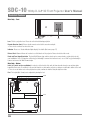
Main Body - Front
Exhaust Vent
Lens
Exhaust Vent
Lens This is a projection lens. Please do not look inside during projection.
Remote Receiver (front) Please aim the remote control at this area when using it.
• There is also a remote receiver at the rear.
Indicator Please see “Status indicator lights display” for details. (Reference page: 17)
Exhaust Vent Warm air flows out in order to cool the interior of the projector. Please do not block the vents.
Bezel and Front Logo Orientation The front Wolf Cinema logo and lens bezel can be removed and re-oriented to best suit
your installation. Use a 2.5mm hex or Allen key [not included] to remove the front lens bezel; use a 1/16” key [not included] to
remove and reverse the Wolf Cinema badge.
Main Body - Bottom
Inlets (at 3 points on the rear/bottom) In order to cool the inside of the unit, air flows from the chassis rear and base plate
toward the front vents. Do not block or prevent air flow into or out from the projector, as doing so could lead to failure of the unit.
• There is one air intake vent on the projector base plate, and two air intakes along the right rear sides.
Feet The height (0 to 5 mm) can be adjusted by turning the foot.
Inlets
Feet
14
SDC-10
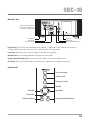
Main Body - Rear
Remove the rear perforated door
panel by turning the thumb screws
in a counter-clockwise direction.
Air Intake Vent
Input Terminal
Power Input Terminal
Lamp Cover
Air Intake Vent
Operation Panel
Remote Control IR Window (rear)
Input Terminal These are the main system interconnect terminals – 2 HDMI inputs, 1 DB15 terminal for PC connection,
1 Component Video input, and so forth, plus ports to connect the optional 3D signal emitter.
Lamp Cover Remove this cover to replace the projector lamp. (Reference page: 62)
Operation Panel See the following illustration “Control panel” for more details.
Remote control IR window (rear) Aim your remote control at this section when using the IR remote.
AC Terminal This is the AC input terminal. It is connected via the supplied power cord. (Reference page: 33)
Operation Panel
STANDBY/ON
To turn on/off power
INPUT
To Switch Inputs
OK
To Select or Confirm
Up Button
Right Button
Left Button
Down Button
MENU
To Access the Menu
BACK
To Return to the Previous Menu
15
SDC-10 1080p D-ILA 3D Front Projector User’s Manual
®
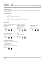
Status Indicator Lights
LED indicators are present during normal operation mode of this unit, and are displayed with the indicators for [STAND BY / ON],
[LAMP], and [WARNING].
Meaning of the indicators:
The indicator light in a steady state.
The indicator light is “flashing” to alert the user to a state change.
Operation Mode
Displays the color and lighting/flashing of the [STAND BY / ON] indicator.
STAND BY Light on (Red)
During stand by
STAND BY/ON LAMP
WARNING
STAND BY Blinking (Green)
When “Hide” is set to ON
STAND BY/ON LAMP
WARNING
STAND BY Light on (Green)
While activating the lamp
(about1minute)
STAND BY/ON LAMP
All Off
During image projection
STAND BY/ON LAMP
Lamp Replacement Indicator
Displays lighting/flashing of the [LAMP] indicator.
LAMP Light On (Orange)
Lamp replacement time is near
(accumulated lamp time exceeds 2900 hours)
STAND BY/ON LAMP
16
WARNING
WARNING
WARNING
STAND BY Blinking (Red)
During cool down
STAND BY/ON LAMP
WARNING
SDC-10
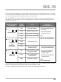
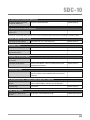
Front panel indicator lights inform you of various operating conditions with the projector. Certain warning notices are provided by
the repeated flashing of the [WARNING] and [LAMP] indicators. Moreover, the [STAND BY / ON] indicator, which shows the operating
mode of the unit, may also be displayed simultaneously with either indicator lights.
During any [WARNING] mode indication, the light output is interrupted for about 60 seconds and the cooling fan is turned on.
Please disconnect the power plug from the electric socket ONLY after the cooling fan has stopped running. Additional indicators
and actions are noted below:
Lighting/Flashing Lights
Status Diagram
STAND BY/ON LAMP
WARNING
(red) Mode Display (*)
STAND BY/ON LAMP
WARNING
Blinking
Frequency
Content
1 time
Power supply problems
2 times
Cooling fan stops running
3 times
Internal temperature is too high
4 times
External temperature is too high
1 time
2 times
(orange) (red)
Mode
Simultaneous
Display Flashing
STAND BY/ON LAMP
WARNING
(orange) (red)
Mode Display
Confirmation
and Countermeasures
• Check that nothing is blocking
the air inlets.
• Insure that the external
temperature is normal.
Action
Leave the unit until it cools down.
After that, turn on the power again.
Faulty electrical circuit
3 times
4 times
Something is wrong with the
automatic lens cover
1 time
Lamp does not light up and does
not project an image
2 times
Lamp is turned off during
projection period
3 times
Lamp cover is removed
• Check that an impact shock has
not occurred during operation.
• Check that the lampunit and
lamp door cover are both
correctly installed.
• Check that nothing is blocking
the auto lens cover.
Action
Turn on the power again.
If any warning indicators are displayed multiple times [after power cycling], please wait for the cooling fan to stop, then carefully
remove the power plug from the AC power outlet. Contact your authorized dealer for repair.
(*) When the scheduled time for the lamp replacement is exceeded, this indicator might also illuminate.
17
SDC-10 1080p D-ILA 3D Front Projector User’s Manual
®
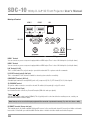
Main Input Terminal
HDMI 2
HDMI 1
LAN
LAN
1
HDMI
2
Component
RS-232C
RS-232-C
CR/PR
CB/PB
Y
Remote
3D
SYNCHRO
PC
TRIGGER REMOTE
CONTROL
3D Synchro
PC
IR Trigger
HDMI 1 Terminal
You can connect any source component equipped with an HDMI output. There is also a M3 locking hole (hole depth 3mm).
HDMI 2 Terminal
You can connect any source component equipped with an HDMI output. There is also a M3 locking hole (hole depth 3mm).
LAN Terminal (RJ-45)
This is a LAN-terminal. The projector may be operated via networked PC or system controller commands.
RS-232C Terminal (male D-Sub 9 pin)
This is a standard RS-232C interface terminal for external system controller connectivity.
COMPONENT Terminals (RCA x 3)
Standard input terminals for analog RGB (Synch on G), component (Y, Cb, Cr), DTV format (Y, Pb, Pr) video signals.
3D SYNCHRO Terminal
3D synchro emitter connector: connect the external 3D emitter (sold separately) to enjoy 3D content.
PC Terminal (D-Sub 15 pin)
Input terminal used to connect any Personal Computer (RGB video and sync signals).
Trigger (
)
12V DC power supply output terminal (100mA). This is typically used to control motorized or masking screens; contact your
Wolf Cinema installer for further details.
Note: Damage can be caused to third party equipment if the connection is performed incorrectly. (Tip = DC +12 V, Sleeve = GND)
IR REMOTE terminal (Stereo mini jack)
This terminal may be used with compatible third party IR sensors, in the event the main chassis IR sensor(s) are hidden or otherwise
inaccessible. Consult with your authorized Wolf Cinema dealer or installer for further details and technical support.
18
SDC-10
Remote Control
Remote Control Features
ON
STAND BY
To Turn OFF the Projector
To Turn ON the Projector
INPUT
This button sequentially switches 3D formats
(*) This function cannot be used when inputing
2D and frame packing 3D singles
HDMI 1
HDMI 2
COMP.
3D
FORMAT
3D
SETTING
ANAMO.
LENS.
CONTROL
LENS
MEMORY
LENS AP.
To select input mode
This sequentially switches anamorphic modes
Display the 3D setting menu
Use this function to sequentially select focus,
zoom and shift adjustment lens controls
HIDE
LIGHT
This sequentially switches the call up/save/edit
modes of your lens memory
To adjust Lens Aperture
To hide the image temporarily
To illustrate buttons on the remote control
for 7 seconds
To select confirm
To display/close the menu
BACK
MENU
To return to previous menu
PICTURE MODE
FILM
CINEMA
ANIME
NATURAL
STAGE
3D
USER
INFO
C.M.D.
To switch picture mode
This sequentially switches between users 1-5
To adjust color temperature
Color Space
GAMMA
To set gamma
Display the information menu
COLOR
TEMP
COLOR
P.FILE
PIC.
ADJ.
Sequentially switched picture adjust items,
such as contrast and brightness. The switching
items are not the same for different models,
or different picture modes
Inserting Batteries into the Remote Control
• Slide open the rear cover, then insert the batteries according to the positive (+) and negative (-) indicator marks. Insert the
(-) end first.
• If an error occurs when using the remote control, remove the batteries and wait for 5 minutes. Load the batteries again and
continue operating the remote control.
19
SDC-10 1080p D-ILA 3D Front Projector User’s Manual
®
About Installation
Important Points Concerning Installation
Please read the following carefully before installation of this projector
Installation Environment
CAUTION
This unit is a precision device. Therefore, please refrain from installation or usage in the following locations, otherwise,
fire or serious malfunction may occur:
•
•
•
•
•
Dust, wet and humid locations.
Sooty or cigarette smoke filled locations.
On top of a carpet or bedding, or other soft surfaces
Locations with very high ambient temperatures - as located in direct sunlight.
Locations with high or low temperatures.
Permissible extreme high or low operating temperature range: +5 º to +35º.
Relative humidity range permissible for operating: 20% ~ 80% (non-condensing).
Storage temperature tolerance: -10º to +60º.
• If the installation of the unit is done in a room with soot and/or smoke over a longer period, even small amounts of
these substances may affect the device. This unit cools its optical components (which produce a great deal of heat)
via air flow through the projector. If the optical circuits get dirty, this might lead to malfunctions, such as the video
images becoming darker or a deterioration of color fidelity. Dirt sticking to the optical components cannot be removed.
Please Perform the Installation at a Set Distance from Walls and Other Devices
CAUTION
For optimum heat dissipation, please keep a minimum distance between this unit and its surroundings as shown in the
following illustration.
Moreover, please keep the front of the unit clear from all obstructions. If there are any objects in front of the exhaust
ports, hot air may flow back into to the unit and cause overheating. Note that hot air exhaust flowing out of the unit
might cause shadows on the screen (heat haze phenomenon).
If the projector is enclosed in a space as shown in the following illustration, please insure that the enclosed interior has
the same temperature as the outside. High temperatures can lead to failure of the unit.
20
SDC-10
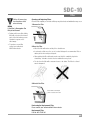
Please Be Careful During Use
CAUTION
This unit uses a projection lamp, which will get hot when in use. Please refrain from projecting in the following circumstances, otherwise, fire or serious malfunctions may occur:
• Projection while lying on its side.
Avoid projection if the installation of the unit is done at an excessive angle of more than ± 30 °. This may reduce life
of the lamp and cause unwanted color shading.
• Avoid projection at any location where the air vents or exhaust ports might get blocked.
Consult with your Wolf Cinema installer as to the optimum screen surface to use with this projector. Note that certain
perforated or woven “acoustic transparent” screens may result in visual interference patterns with the pixel array of the
D-ILA light engine components. One way to reduce any unwanted interference pattern is to change the size of the
screen, or type of screen surface, so that any interference patterns will be less noticeable.
Inclination Adjustment for this Projector
How to Adjust the Vertical Angle
Height and inclination of the unit (0 ~ 5mm) can be adjusted by rotating its feet. Lift the unit and adjust the four feet.
Stand
Extend
Contract
21
SDC-10 1080p D-ILA 3D Front Projector User’s Manual
®
Installing the Projector and Screen
While installing, please place this unit and the screen perpendicular to each other. Failing to do so may increase trapezoidal distortion.
Set Angle
The angle range which can be set for this projector is ±30°.
• Malfunctions may occur if the angle is not set within the above range.
Shift
Left/Right Position
* 0% up/down position (center)
Approximately 34% (maximum) of the projected image
Approximately 34% (maximum) of the projected image
Up/Down Position
* 0% left/right position (center)
Approximately 80% (maximum) of the projected image
Lens shift correlation chart:
Lens Shift
Movement Range
Vertical lens shift
(%)
Approximately 80% (maximum) of the projected image
90
80
70
60
50
Left-Right Shift(%)
0%
10%
20%
30%
34%
40
Up-Down Shift (%)
80%
66%
47%
18%
0%
30
• Maximum Up-Down shift varies with the amount of Left-Right shift.
Likewise, maximum Left-Right shift varies with the amount of Up- Down shift.
• The values on the chart are intended to act as a guide.
Use them for reference during installation.
22
20
Lens movability range
10
0
10
20
30
Horizontal lens shift
(%)
40
SDC-10
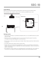
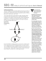
Projector Mounting
Measures to prevent the unit from toppling or dropping should be used for safety reasons and accident prevention.
When mounting this unit on a pedestal or ceiling, use all the 4 screw holes provided (M5 screws) to mount.
Ceiling
Bottom Surface
Air Inlets
4 x M5 Screws
Mounting Precautions
• Special expertise and techniques are required when mounting this unit. Be sure to ask your Wolf Cinema dealer to perform
all desired mounting.
• Depth of the screw holes (screw length) is 23 mm. Use screws shorter than 23 mm but longer than 13 mm. Using
non-compliant screws may result in malfunctions or cause the unit to drop.
• When mounting to a pedestal, ensure sufficient space (foot height of 10 mm or higher) around the unit so that the air inlets
are not blocked.
• Do not tilt this unit more than ±5 degrees from side to side when using.
• Regardless whether the unit is still under warranty, Wolf Cinema is not liable for any product damage caused by improper
mounting, or mounting the unit with non-compliant Wolf Cinema ceiling mounting hardware, or when the environment is not
suitable for ceiling mounting.
• When hanging from a ceiling, pay attention to the surrounding temperature. Note that during colder seasons and whenever
a room heater is in use, temperature around the ceiling will be higher than expected and may damage the projector.
23
SDC-10 1080p D-ILA 3D Front Projector User’s Manual
®
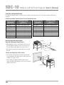
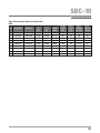
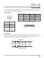
Screen Size and Projection Distance
Determine the distance from the lens to the screen to achieve your desired screen size. This projector features a 2.0x power
zoom lens.
Relationship Between Projection Screen Size and Projection Distance
Projection Screen Size
(Height, Width)
Aspect Ratio 16:9
Approximate Projection
Distance
W(Wide) to T(Tele)
Projection Screen Size
(Height, Width)
Aspect Ratio 16:9
Approximate Projection
Distance
W(Wide) to T(Tele)
60” (Approx. 0.7, 1.3m)
Approx.1.78m to Approx.3.66m
140” (Approx.1.7, 3.1m)
Approx.4.23 m to Approx.8.60m
70” (Approx.0.9, 1.5m)
Approx.2.09m to Approx.4.28m
150” (Approx.1.9, 3.3m)
Approx.4.53m to Approx.9.22m
80” (Approx.1.0, 1.8m)
Approx.2.40m to Approx.4.89m
160” (Approx.2.0, 3.5m)
Approx.4.84m to Approx.9.84m
90” (Approx.1.1, 2.0m)
Approx.2.70m to Approx.5.51m
170” (Approx.2.1, 3.8m)
Approx.5.14m to Approx.10.45m
100” (Approx.1.2, 2.2m)
Approx.3.01m to Approx.6.13m
180” (Approx.2.2, 4.0m)
Approx.5.45m to Approx.11.07m
110” (Approx.1.4, 2.4m)
Approx.3.31m to Approx.6.75m
190” (Approx.2.4, 4.2m)
Approx.5.75m to Approx.11.68m
120” (Approx.1.5, 2.7m)
Approx.3.62m to Approx.7.36m
200” (Approx.2.5, 4.4m)
Approx.6.06m to Approx.12.30m
130” (Approx.1.6, 2.9m)
Approx.3.92m to Approx.7.98m
This Unit
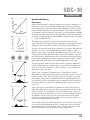
Effective Range of IR Remote Control
Aim the IR remote control toward the unit.
30°
• When aiming the remote control towards the IR sensor on
this unit, maintain a distance to the sensor (in front or at
the rear of this projector) within 7 m or appx. 23 feet.
30°
20°
20°
• If the remote control fails to work properly, move closer to
this unit.
Remote Control
“Bounce” the IR Signal off a Wall or Screen
• Insure that the total of distance A between this unit and
screen and distance B between remote control and screen
is within 7 m.or appx. 23 feet.
• As the efficiency of signals reflected from the remote
control unit will vary with the type of screen used, operable
distance may decrease.
30°
20°
20°
A
B
Screen
Remote Control
24
30°
This Unit
SDC-10
Making the Connection
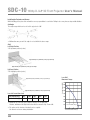
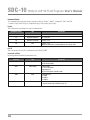
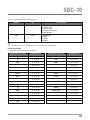
Types of Possible Input Signals (PC Compatible)
HDMI
No.
Designation
Resolution
fh
[kHz]
fv
[Hz]
dot CLK
[MHz]
Total No.
of dots
[dot]
Total No.
of lines
[line]
No. of
effective
dots [dot]
No. of
effective
lines [line]
1
VGA 60
640 X 480
31.500
60.000
25.200
800
525
640
480
2
VGA 59.94
640 X 480
31.469
59.940
25.175
800
525
640
480
3
SVGA 60
800 X 600
37.879
60.317
40.000
1,056
628
800
600
4
XGA 60
1024 X 768
48.363
60.004
65.000
1,344
806
1,024
768
5
WXGA 60
1280 X 768
47.760
60.000
79.998
1,675
796
1,280
768
6
WXGA +60
1440 X 900
55.919
59.999
106.470
1,904
932
1,440
900
7
SXGA 60
1280 X 1024
63.981
60.020
108.000
1,688
1,066
1,280
1,024
8
WSXGA +60
1680 X 1050
65.222
60.002
147.140
2,256
1,087
1,680
1,050
9
WUXGA 60
1920 X 1200
74.038
59.95
154.000
2,080
1,235
1,920
1,200
25
SDC-10 1080p D-ILA 3D Front Projector User’s Manual
®
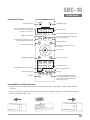
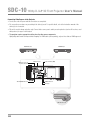
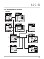
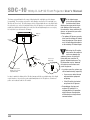
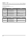
Connecting Video Sources to the Projector
• Do not turn on the AC power until all connections are completed.
• The connection procedures vary according to the device(s) used. For specific details, refer to the instruction manual of the
device(s) to be connected.
• This unit is used for image projection only. Connect video source gear to audio processing devices (such as AV receivers, used
with speakers) for proper sound output.
• The projector requires appropriate cabling from the video source components.
High quality cables make for improved video imaging. For HDMI cables (sold separately), only use those that are HDMI-approved.
BD/DVD Recorder
BD/DVD Player
LAN Control Port
Component Video (RGB)
HDMI Connectors (x2)
RS-232 Control Port
STANDBY/ON
INPUT
1
HDMI
2
OK
RS-232-C
3D
SYNCHRO
CR/PR CB/PB
PC
Y
REMOTE
TRIGGER CONTROL
MENU
3D SYNCHRO Emitter Port
PC
26
BACK
REMOTE IR Sensor
DC Trigger
VCR and Camcorder
SDC-10
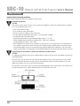
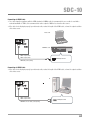
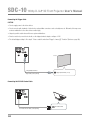
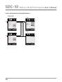
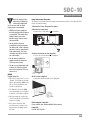
Connecting via HDMI Cable
• For a video signal in compliance with the HDMI standard, a 340MHz cable is recommended. In case a cable is used with a
reduced bandwidth of 75MHz, it is recommended to reduce output to 1080i or less from the video source.
• If the video is not displayed properly, try an alternate cable, reduce the length of the HDMI cable, or lower the output resolution
of the video source.
Notebook PC
LAN
1
HDMI
2
RS-232-C
3D
SYNCHRO
CR/PR
CB/PB
Y
TRIGGER REMOTE
CONTROL
PC
BD/DVD Recorder
HDMI 1 Input Terminal
HDMI 2 Input Terminal
HDMI Output Terminal
HDMI Cable (sold separately)
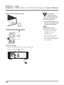
Connecting via HDMI Cable
• If the video is not displayed properly, try an alternate cable, reduce the length of the HDMI cable, or lower the output resolution
of the video source.
PC
LAN
1
HDMI
RS-232-C
3D
SYNCHRO
2
CR/PR
PC
CB/PB
Y
TRIGGER REMOTE
CONTROL
HDMI 1 Input Terminal
HDMI 2 Input Terminal
DVI Output Terminal
HDMI-DVI Conversion Cable (sold separately)
27
SDC-10 1080p D-ILA 3D Front Projector User’s Manual
®
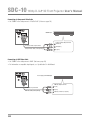
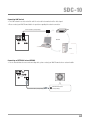
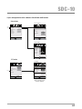
Connecting via Component Video Cable
• Set “COMP.” in the setting menu to “Y Pb/Cb Pr/Cr”. (Reference page: 54)
LAN
1
HDMI
2
RS-232-C
3D
SYNCHRO
BD/DVD Player
CR/PR
CB/PB
PC
Y
TRIGGER REMOTE
CONTROL
Component Video Output Terminals
CR/PR (red)
To Component Video Input Terminals
CB/PB (blue)
Component Video Cable (sold separately)
Y (green)
Connecting via RGB Video Cable
• Set “COMP.” in the setting menu to “RGB”. (Reference page: 54)
• For information on compatible input signals, see “Specifications” in this Manual.
LAN
1
HDMI
RS-232-C
3D
SYNCHRO
2
Device Equipped with RGB Output
CR/PR
PC
CB/PB
Y
TRIGGER REMOTE
CONTROL
RGB Video Output Terminals
R (red)
To RGB Video Input Terminals
B (blue)
RGB Video Cable (sold separately)
28
G(Green) (Includes Sync Signals)
SDC-10
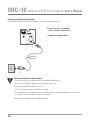
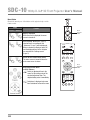
Connecting a 3D Emitter
• 3D emitter: This is a dedicated terminal for an optional 3D signal emitter (sold separately).
• 3D glasses are optional devices, used in conjunction with the 3D emitter.
CAUTION
• 3D image quality may vary depending on the ambient room temperature and lamp usage. Stop using the projector in 3D
modes if images cannot be projected correctly.
• Before you watch 3D video images, make sure to read “3D Viewing” (Reference pages 59 to 61).
LAN
1
HDMI
2
3D-Glasses
RS-232-C
3D
SYNCHRO
CR/PR
PC
CB/PB
Y
TRIGGER REMOTE
CONTROL
3D Emitter
29
SDC-10 1080p D-ILA 3D Front Projector User’s Manual
®
Connecting the Trigger Cable
CAUTION
• Do not supply power to the other devices.
• Do not connect audio terminals of other devices using similar connectors such as headphones etc. Otherwise, this may cause
a serious malfunction to the other devices and/or injury.
• Usage beyond the rated values will cause system malfunctions.
• Exercise caution to prevent short circuits, as the trigger terminal outputs a voltage of 12V.
• The default trigger setting is “No output”. Please enable it under item “Trigger” of menu [5] "Function” (Reference page: 56).
LAN
1
HDMI
2
CR/PR
RS-232-C
3D
SYNCHRO
CB/PB
PC
Y
TRIGGER REMOTE
CONTROL
To Trigger Output Terminal
Trigger Cable (sold separately)
Screen
Trigger Input Terminals ( Φ 3.5)
Connecting the RS-232C Control Cable
LAN
1
HDMI
2
RS-232-C
3D
SYNCHRO
CR/PR
PC
CB/PB
Y
TRIGGER REMOTE
CONTROL
RS-232C Terminal
RS-232C Connection Cable (sold separately)
30
SDC-10
Connecting LAN Terminal
• The LAN network is used to control the unit. It is not used for transmission of the video signal.
• Please contact your Wolf Cinema installer for questions regarding the network connection.
Connection Cable (sold separately)
HUB
LAN
1
HDMI
2
Network
CR/PR
RS-232-C
3D
SYNCHRO
CB/PB
PC
Y
TRIGGER REMOTE
CONTROL
Server
Connecting an EXTERNAL Infrared SENSOR
• For an external infrared sensor and connecting cable, please contact your Wolf Cinema dealer or custom installer.
LAN
1
HDMI
RS-232-C
3D
SYNCHRO
2
CR/PR
PC
CB/PB
Y
TRIGGER REMOTE
CONTROL
IR Connection Cable (sold separately)
External Infrared Sensor
(sold separately)
31
SDC-10 1080p D-ILA 3D Front Projector User’s Manual
®
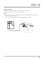
Connecting the AC Power Cord (provided)
Once you have connected all video source equipment, connect the projector AC power cord.
STANDBY/ON
INPUT
1
HDMI
1
HDMI
2
3D
SYNCHRO
3D
SYNCHRO
1 Connect the power cord supplied
with the unit power input terminal
OK
2
RS-232-C
RS-232-C
LAN
CR/PR CB/PB
CR/PR
PC
PC
CB/PB
Y
Y
2 Connect to the power outlet
REMOTE
TRIGGER CONTROL
TRIGGER REMOTE
CONTROL
MENU
BACK
1
Power Cord
(Supplied)
2
Be Careful to Avoid Fire and Electric Shocks
• Please connect the projector directly into the nearest available AC wall outlet.
• When you are not using the equipment, please unplug the power cord.
• Connect it only with the provided AC power cord.
• Do not use voltage other than the indicated power voltage.
• Do not damage, break or modify the power cord. Note that the power cord may be damaged if you place it under
heavy objects, expose it to high heat or pull it too excessively.
• Never handle or unplug the power cord with wet hands.
32
SDC-10
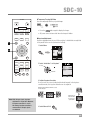
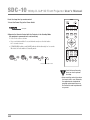
Basic Operation
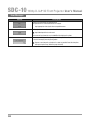
Basic Operation Procedures
Once you have completed all source component connections, the projector can be used with the following basic steps.
6
1 Turn On Power
1
ON
STANDBY/ON
Light on (Green)
ON
STAND BY
• You can also press the
INPUT
HDMI 1
HDMI 2
COMP.
3D
FORMAT
3D
SETTING
ANAMO.
LENS.
CONTROL
LENS
MEMORY
LENS AP.
HIDE
2
• Remove the lens cover
[*] Be sure to remove the lens cover prior to use. Projection with
removing the lens cover may cause serious damage to the projector
and/or the projector optics.
2 Select Video Input
LIGHT
3
Select Input
• You can also select the desired source by pressing
button repeatedly on the unit.
HDMI 1
4
5
BACK
MENU
button on the unit to turn on the power.
HDMI 2
INPUT
the input
COMP.
Play Back the Selected Device
3 Adjust Image Zoom (screen size)
PICTURE MODE
FILM
CINEMA
ANIME
NATURAL
STAGE
3D
USER
INFO
C.M.D.
GAMMA
COLOR
TEMP
COLOR
P.FILE
LENS
Adjust accordingly
by pressing the
Up/Down buttons
PIC.
ADJ.
4 Adjust Image Focus (focal point)
LENS
Adjust accordingly
by pressing the
Up/Down buttons
33
SDC-10 1080p D-ILA 3D Front Projector User’s Manual
®
MEMO
About Cool Down Mode
• The Cool Down mode is a procedure
to cool the lamp for approximately
60 seconds after turning off the
projector. This function prevents
the internal parts of the unit from
deformation or damage due to lamp
overheating. It also prevents lamp
failure and premature shortening
of lamp life.
5 Adjust Lens Shift (image position)
• After adjusting the image position, it may be necessary to select “Pixel
Adjust” from the Settings menu “Installation”. (Reference page:55)
• Every time the
button is pressed, the adjustment action will be
switched between “Focus”, “Zoom” and “Shift”.
OK
It can also be switched with the button.
LENS
• During Cool Down mode, the
[STANDBY/ON] indicator blinks red.
• Once the Cool Down mode is
complete, the unit automatically
returns to the standby mode.
• DO NOT pull out the AC power plug
during Cool Down mode. This may
shorten the lamp life and cause
major system malfunctions.
LENS
Adjust accordingly
by pressing the
Up/Down/Left/Right buttons
6 Turn Off Power
• AC power cannot be turned off for approximately 90 seconds once it has
been turned on. Begin operations only after 90 seconds time.
• You can also press the
button on the unit to turn off AC power.
• Carefully remove the AC power plug if the unit will not be used for a
prolonged period of time.
While a Confirmation Screen is Displayed
Blinking (Red Lamp)
Cool Down Mode
Light On (Red Lamp)
34
* Need to address “A” input
SDC-10
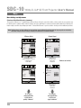
Setting the Screen Size
ON
STAND BY
INPUT
HDMI 1
HDMI 2
COMP.
3D
FORMAT
3D
SETTING
ANAMO.
LENS.
CONTROL
LENS
MEMORY
LENS AP.
Image Sizing and Aspect Ratio
[Refer also to page 36 of the SDC-15 User’s Manual]
You can quickly change the screen size (aspect ratio) of the projected image,
or mask image borders as desired if the surrounding edges of the image area
are distorted.
Setting the Screen Size (Aspect Ratio)
The projected image can be set to a desired screen size and aspect ratio.
1 Select Menu
HIDE
LIGHT
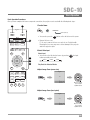
MENU
Picture Adjust
Picture Mode
Film
Color Profile
Color Temp.
Gamma
Film Tone
Contrast
Brightness
Color
Tint
Film1
Advanced
A
Film1
0
0
0
0
Reset
Operate
Exit
MENU
Xenon1
Select
Back
BACK
BACK
MENU
2 Select “Input Signal” ➔ “Aspect [Video]”
PICTURE MODE
FILM
CINEMA
ANIME
NATURAL
STAGE
3D
Input Signal
HDMI
1 Select
COMP.
PC
Picture Position
2 Confirm
USER
INFO
Aspect (Video)
4:3
Mask
off
Progressive
Auto
3D Setting
C.M.D.
Operate
Exit
MENU
GAMMA
COLOR
TEMP
COLOR
P.FILE
4:3
16:9
Custom
Select
Back
BACK
PIC.
ADJ.
3 Set a Aspect Value
Input Signal
HDMI
1 Select
COMP.
PC
Picture Position
Aspect (Video)
2 Confirm
16:9
Mask
off
Progressive
Auto
4:3
16:9
Custom
3D Setting
Operate
Exit
MENU
Select
Back
BACK
35
SDC-10 1080p D-ILA 3D Front Projector User’s Manual
®
ON
STAND BY
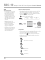
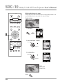
B Masking the Borders of an Image
Images where the borders have deteriorated, or image quality reduced can be
masked (hidden) from the main body of the projected image.
Project an Image
INPUT
HDMI 1
HDMI 2
COMP.
3D
FORMAT
3D
SETTING
ANAMO.
LENS.
CONTROL
LENS
MEMORY
LENS AP.
HIDE
LIGHT
1 Select Menu
Picture Adjust
Picture Mode
Color Profile
Color Temp.
Gamma
Film Tone
Contrast
Brightness
Color
Tint
MENU
B
Film
Film1
Xenon1
Film1
0
0
0
0
Reset
Advanced
Operate
Exit
MENU
Back
BACK
Select
BACK
MENU
2 Select “Input Signal” ➔ “Mask”
PICTURE MODE
FILM
CINEMA
ANIME
Input Signal
HDMI
1 Select
COMP.
PC
Picture Position
NATURAL
STAGE
3D
2 Confirm
USER
INFO
Aspect (Video)
16:9
Mask
Off
2.5%
5%
Progressive
Auto
Off
Custom
C.M.D.
Operate
Exit
MENU
GAMMA
COLOR
TEMP
COLOR
P.FILE
Select
Back
BACK
PIC.
ADJ.
3 Set a Mask Value
Input Signal
HDMI
1 Select
COMP.
PC
Picture Position
Aspect (Video)
Mask
2 Confirm
Progressive
Select
Example:
When the “Mask”
value is changed
from “Off” ➔ “5%”
To End
36
MENU
5%
2.5%
5%
Auto
Off
Custom
Operate
Exit
MENU
16:9
Back
BACK
SDC-10
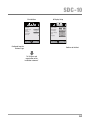
ON
STAND BY
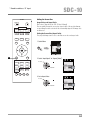
C Temporary Turning-Off Video
You can temporarily hide the projected image.
INPUT
C
HDMI 1
HDMI 2
COMP.
3D
FORMAT
3D
SETTING
ANAMO.
LENS.
CONTROL
LENS
MEMORY
LENS AP.
HIDE
LIGHT
• Press the
HIDE
button again to display the image.
• AC power cannot be turned off when the image is hidden.
D Keystone Adjustment
Keystone adjustment may be used if the projector is installed at an angle that
is not parallel to the screen (horizontal or vertical).
1 Select Menu
D
MENU
Picture Adjust
Picture Mode
Film
Color Profile
Color Temp.
Gamma
Film Tone
Contrast
Brightness
Color
Tint
Film1
Advanced
BACK
MENU
Film1
0
0
0
0
Reset
Operate
Exit
MENU
Xenon1
Select
Back
BACK
PICTURE MODE
FILM
NATURAL
CINEMA
STAGE
ANIME
3D
2 Select “Installation” ➔ “Keystone”
Installation
Lens Control
1 Select
Pixel Adjust
Installation Style
Front
Keystone
USER
INFO
Anamorphic
C.M.D.
Off
Screen Adjust
Black Level
2 Confirm
GAMMA
COLOR
TEMP
COLOR
P.FILE
PIC.
ADJ.
Operate
Exit
MENU
Select
Back
BACK
3 Adjusts Keystone Correction
If one presses the cursor (vertical and horizontal arrows) in the keystone
correction mode, the keystone distortion can be adjusted.
Adjust horizontal distortion with the cursors
for left and right.
Note: With 3D input signals, keystone
adjustment is not possible. Moreover,
if keystone correction is used in
2D viewing, keystone correction is
removed when 3D input signals
are detected.
Adjust vertical
distortion with
the cursors for
up and down.
4 Select Menu to Exit
MENU
37
SDC-10 1080p D-ILA 3D Front Projector User’s Manual
®
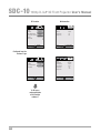
Menu
Menu Settings and Adjustments
Structure of the Menu Hierarchy (summary)
The projector’s Menu “tree” is organized generally as follows. As this is only a brief outline, certain controls in your projector may
be different due to software and/or feature changes; also there will likely be certain menu items which might not be displayed or
made readily accessible depending upon model. Contact Wolf Cinema or your local dealer should you have additional questions.
Note: That the values and final settings for your projector may be different than illustrated, due to your particular installation
calibration and personalized settings. Contact your Wolf Dealer for additional details.
2 Input Signal
1 Picture Adjust
Input Signal
Picture Adjust
Picture Mode
(*)
Color Profile
Color Temp.
Gamma
Film Tone
Contrast
Brightness
Color
Tint
Film
COMP.
Film1
Xenon1
PC
Film1
Picture Position
(*)
0
Aspect(Video)
Mask
Off
0
Progressive
Auto
0
Reset
Operate
Exit
Back
Operate
Exit
BACK
Select
MENU
(*) Apart from “Film”,
“Brightness/darkness correction”
is displayed in the
“Picture Mode”.
Back
Select
BACK
(*) When there is
a PC signal input,
“Aspect (PC)”
is displayed.
Continue to the Next
Input Signal
Picture Adjust
Picture Mode
Contrast
Brightness
Color
Tint
Color Temp.
Gamma
Advanced
16:9
0
Advanced
MENU
HDMI
Natural
HDMI
COMP.
0
0
Picture Position
0
(*)
0
Aspect(Video)
16:9
6500K
Mask
Off
Normal
Progressive
Auto
Reset
Operate
Exit
MENU
Back
Select
BACK
Operate
Exit
MENU
Back
Select
(*) When there is a
PC signal input,
“Aspect (PC)”
is displayed.
To “1 Layers
and organization
of the picture
quality submenu”
38
To “2 Layers
and organization
of the input
signal submenu”
BACK
SDC-10
3 Installation
4 Display Setup
Installation
Display Setup
Lens Control
Back Color
Pixel Adjust
Menu Position
Installation Style
Keystone
Anamorphic
Front
Menu Display
Line Display
Off
Source Display
Screen Adjust
Black Level
Select
Back
BACK
Continued from the
Previous Page
On
English
Operate
Exit
MENU
On
5 sec
On
Language
Operate
Exit
MENU
Logo
Black
Select
Back
BACK
Continue to the Next
To “3 Layers and
organization of the
installation submenu”
39
SDC-10 1080p D-ILA 3D Front Projector User’s Manual
®
6 Information
5 Function
Information
Function
Trigger
Off
Input
:
HDMI-2
Off Timer
Off
Source
:
1080p60
High Altitude Mode
Off
Deep Color
:
10bit
Communication Terminal
LAN
Lamp Time
:
160H
Network
Lamp Reset
Operate
Exit
MENU
Back
BACK
Select
Operate
Exit
MENU
Back
BACK
Select
Continued from the
Previous Page
Information
Function
Trigger
Off
Off Timer
Off
High Altitude Mode
Off
Lamp Reset
Operate
Exit
MENU
Back
Select
BACK
Input
Resolution
H Frequency
:
PC
:
1920X1080
:
67.50kHz
V Frequency
Deep Color
:
60.0Hz
:
8bit
Lamp Time
:
160H
Operate
Exit
MENU
Select
For PC signal input
To “5 Layers
and organization
of the function
submenu”
40
Back
BACK
SDC-10
1 Layers and Organization of the Picture Adjust Submenus
1 Picture Adjust
1-1 Color Temperature
Picture Adjust
Picture Adjust
1-1
1-2
Picture Mode
Film
Color Profile
Color Temp.
Gamma
Film Tone
Contrast
Brightness
Color
Tint
Film1
Preset
Xenon1
Custom1
Custom2
Custom3
Color Temp.
Film1
5500K
6000K
6500K
7000K
7500K
8000K
8500K
9000K
9500K
Xenon1
Xenon1
Gain Red
Gain Green
Gain Blue
Offset Red
Offset Green
Offset Blue
0
0
0
0
0
0
0
0
0
Reset
0
Xenon2
Xenon3
Reset
Advanced
Operate
Exit
MENU
>
Back
Exit
Operate Back
MENU Select
BACK
Select
BACK
1-2-1 Sharpness
Picture Mode
1-1
1-2
Contrast
Brightness
Color
Tint
Color Temp.
Gamma
Advanced
Picture Adjust
Picture Adjust
Picture Adjust
Natural
>
0
Preset
0
Custom1
Custom2
Custom3
0
0
5500K
6000K
6500K
7000K
7500K
8000K
8500K
9000K
9500K
6500K
Gain Red
Gain Green
Gain Blue
Offset Red
Offset Green
Offset Blue
6500K
Normal
Sharpness
>>
Color Temp.
0
0
0
0
0
Sharpness
25
Detail Enhance
0
High Brightness
0
Reset
Reset
Operate
Exit
MENU
Back
Exit
MENU Select
BACK
Select
1-2 Advanced
1-2-1
1-2-2
1-2-3
>>
Back
BACK
Select
Custom Gamma
Custom1
Custom2
Custom3
Off
Off
Correction Value
White 1023
Red
Green
Blue
512
Normal
0
Normal
Operate
Exit
MENU
MENU
Picture Adjust
Advanced
Sharpness
NR
Custom Gamma
Color Management
Clear Motion Drive
CMD Demo
Lens Aperture
Lamp Power
Operate
Exit
BACK
1-2-2 Custom Gamma
Picture Adjust
>
Operate Back
Reset
Back
Exit
MENU
BACK
Select
0
50
100(%)
Operate Back
BACK
Select
1-2-3 Color Management
Picture Adjust
>
1-2-1
1-2-2
Picture Adjust
Advanced
Sharpness
NR
Color Space
Custom Gamma
Clear Motion Drive
CMD Demo
Lens Aperture
Lamp Power
Select
Color Management
Off
Standard
Off
Custom1
Custom2
Custom3
Pause
Off
Reset
0
Normal
Operate
Exit
MENU
>>
Back
BACK
Color Selection
0
Axis Position
0
Hue
0
Saturation
0
Brightness
Exit
Operate Back
MENU Select
BACK
Red
41
SDC-10 1080p D-ILA 3D Front Projector User’s Manual
®
2 Layers and Organization of the Input Signal Submenu
2 Input Signal
2-1 HDMI
Input Signal
2-1
2-2
2-3
Input Signal
HDMI
HDMI
COMP.
Input
PC
Level Check
Picture Position
Enhanced
Color Space
Auto
Aspect(Video)
16:9
Control with HDMI
Off
Mask
Off
3D Format
Auto
Progressive
Auto
Operate
Exit
MENU
Back
Select
BACK
Operate
Exit
MENU
Select
Back
BACK
2-2 COMP.
Input Signal
2-1
2-2
Input Signal
COMP.
HDMI
Color Space
COMP.
Y Pb/Cb Pr/Cr
Picture Position
Aspect(Video)
Off
Progressive
Auto
Operate
Exit
MENU
42
16:9
Mask
Select
Back
BACK
Operate
Exit
MENU
Select
Back
BACK
SDC-10
Layers and organization of the submenus 3 installation and 5 function
3 Installation
3-1 Lens Control
Installation
3-1
3-2
Installation
Lens Control
Lens Control
Pixel Adjust
Focus
Installation Style
Front
Keystone
Anamorphic
Zoom
Shift
Off
Lens Cover
Screen Adjust
Black Level
Operate
Exit
MENU
Back
Select
Auto
Image Pattern
On
Lock
Off
Operate
Exit
BACK
MENU
Select
Back
BACK
3-2 Pixel Adjust
Installation
Pixel Adjust
Horiz. Red
3
Horiz. Green
3
Horiz. Blue
3
Vert. Red
3
Vert. Green
3
Vert. Blue
3
Operate
Exit
MENU
Back
BACK
Select
5 Function
5-1 Network
Function
Function
5-1
Network
Trigger
Off
Off Timer
Off
High Altitude Mode
Off
Communication Terminal
LAN
DHCP Client
Off
IP Address
Subnet Mask
Default Gateway
Network
(*)
Lamp Reset
MAC Address
192. 168. 0. 2
255. 255. 255. 0
192. 168. 0.254
:
AA-BB-CC-DD-EE-FF
Set
Operate
Exit
MENU
Select
Back
BACK
Operate
Exit
MENU
Select
Back
BACK
(*) MAC address is
different depending on the
respective equipment.
43
SDC-10 1080p D-ILA 3D Front Projector User’s Manual
®
Menu Button
Operate the menu by use of the buttons on the projector body or on the
remote control.
STANDBY/ON
INPUT
OK
Button
Projector
Function
IR Remote
Menu
Operation
Button
Menu is Displayed
While the menu is displayed, the menu
screen is turned off.
While showing “Main menu” (Layer 1)
selected items are confirmed, and
“Submenus” (Layer 2) will be displayed.
When a submenu is displayed, press OK,
and the displayed items in the selection
are moved to the “Settings screen”
(Layer 3).
Return to the Previous Menu Screen
The menu screen is turned off when the
main menu screen is shown.
Displaying the Main Menu
and the Submenu
/ :Select an adjustment item in the
menu. Set the setting value of the
selected adjustment item. The
adjusted setting value is immediately.
/ :Selection of a displayed sub-menu
item. Selection of an item in the menu.
44
MENU
BACK
ON
STAND BY
INPUT
HDMI 1
HDMI 2
COMP.
3D
FORMAT
3D
SETTING
ANAMO.
LENS.
CONTROL
LENS
MEMORY
LENS AP.
HIDE
LIGHT
Menu
Operation
Button
BACK
MENU
PICTURE MODE
FILM
CINEMA
ANIME
NATURAL
STAGE
3D
USER
INFO
C.M.D.
GAMMA
COLOR
TEMP
COLOR
P.FILE
PIC.
ADJ.
SDC-10
Menu Operation Procedures
STANDBY/ON
1 Press MENU
The main menu is displayed on the screen.
INPUT
OK
3
3
Picture Adjust
5
2
MENU
4
BACK
1
6
Picture Mode
Film
Color Profile
Color Temp.
Gamma
Film Tone
Contrast
Brightness
Color
Tint
Film1
Xenon1
Film1
0
0
0
Reset
Operate
Exit
MENU
ON
HDMI 2
COMP.
3D
FORMAT
3D
SETTING
ANAMO.
LENS.
CONTROL
LENS
MEMORY
LENS AP.
HIDE
Back
BACK
Select
Example: Picture Adjust
2 Press Cursor ( / ) to Select a Submenu
• A submenu (picture adjust, input signal, installation, display setup, function,
information) may be selected:
INPUT
HDMI 1
The submenu items, which are currently selected,
are displayed.
0
Advanced
STAND BY
The submenu items, which are currently selected, are
shown. Currently selected menu items are highlighted and
the icon is colored in orange.
• If one selects “Information”, information about the currently selected video input
and PC input are displayed at the bottom of the menu.
3 Press OK or cursor ( / )
• Sub-menu item is displayed.
LIGHT
3
4
2
5
• Sub-menu items vary depending on the input signal and the picture mode.
See “Content menu” on the next page for more details.
3
Information
Information
1
BACK
MENU
PICTURE MODE
FILM
CINEMA
ANIME
NATURAL
STAGE
3D
USER
INFO
C.M.D.
6
Input
:
HDMI-2
Source
:
1080p60
Deep Color
:
10bit
Lamp Time
:
160H
MENU
GAMMA
COLOR
TEMP
COLOR
P.FILE
Operate
Exit
Select
Back
BACK
Example:
Input signals other
than PC signals
Input
Resolution
H Frequency
:
PC
:
1920X1080
:
67.50kHz
V Frequency
Deep Color
:
60.0Hz
:
8bit
Lamp Time
:
160H
Operate
Exit
MENU
Select
Back
BACK
Example:
When inputting
PC signals
PIC.
ADJ.
4 Press the Cursor ( / ) to Select the Items to Adjust
If the name of a submenu item is dimmed, it cannot be selected.
5 Press Cursor ( / ) to Change Settings
6 After Adjusting, Press BACK
Every time it is pressed, you will return to the previous menu screen.
7 Repeat Steps 6-2 to Adjust Other Items
After all adjustments are done, press MENU, and the menu disappears from the screen.
45
SDC-10 1080p D-ILA 3D Front Projector User’s Manual
®
Menu Item Descriptions
All numbers for the items within [ ] are default settings.
• It is possible to operate all items displayed in the menu display by pressing OK/BACK or the cursor (up, down, left, right arrows).
• Displayed items vary depending on the selected item in the menu and type of input signal (or absence of any signal).
1 Picture Adjust
Picture Mode
Please refer to the description of each mode, and then use the mode best suited for you. Moreover, it is possible to adjust the image
quality by selecting User 1, 2, and 3.
Settings: Film, Cinema, Animation, Natural, Stage, 3D, User 1-5.
[Natural]
Film
Cinema
This image setting is calibrated to best suit film, and may be thus used for watching movies in general.
This image setting is based on the DCI standard and brings to life brightly colored pictures. Suitable for viewing action movies and
brightly-colored images. [DCI: Shorthand for Digital Cinema Initiative].
Animation
Natural
Stage
3D
An image setting calibrated for animation films.
An image setting featuring natural colors/tonality. Suitable for viewing a wide variety of video material [ex: TV dramas/serials].
This image setting is best for watching live events, concerts and theater presentations.
This is the image setting for watching 3D movies.
User 1-5
User settings 1-5 are available for individual calibration, as desired. Last adjustments made are saved into memory.
User 1 is hand calibrated by Wolf factory technicians and may be adjusted to compensate to your specific screen type.
Color Profile
These are adjustable color profiles to best suit the source material. Depending on the settings, the items that can be changed in the
“Picture Mode” will vary. (See Table 1)
The color profile is typically selected based on preferences and video content.
(*) If you select “Off”, it is impossible to perform any picture adjust for other color temp. other than “Lamp Power” and “Lens Aperture”
under “Advanced”, and also “Gamma” or “Sharpness.”
Settings: Film 1, Film 2, Cinema 1, Cinema 2, Standard, Anime 1, Anime 2, Video, Vivid, Adobe, Stage, 3D, Off.
Depending on the picture mode, the default values will change. [See table 1]
Film 2
This is a profile that comes closest to the color space of a Xenon lamp, with films made under the Eastman Kodak Company
film process.
This is a profile that comes closest to the color space of a Xenon lamp, with films made under the FUJIFILM Corporation process.
Cinema 1
Cinema 2
Standard
This is a profile that resembles the color space of the DCI film standards.
This is a profile that resembles the color space of HDTV.
This profile closely represents the film-specific color space of HDTV content. [HDTV: Shorthand for High Definition Television].
Anime 1
This is a profile suitable for CG animation, which can be often found in Hollywood- produced animated TV or film series.
[This profile is intended for content with bright colors].
This is a profile suitable for animation cel-style animation series, which are more common in Japan.
[This profile is intended for animation with more dim colors].
Film 1
Anime 2
Video
Vivid
Adobe
This profile is suitable for general TV / drama / sports viewing.
This is a profile with richer sense of color, often suitable for video games.
This is the color profile best suited for Adobe* RGB.
(*) Adobe, and the Adobe logo are registered trademarks or trademarks of Adobe Systems, as Incorporated in the United States and/or other countries.
Stage
3D
Off
46
This profile is suitable for live music, orchestral and opera concerts, theater, etc.
This is the most suitable profile when using 3D-glasses.
This mode does not enable color management adjustment.
SDC-10
[Table 1] The Settings and Default Values of the Picture Mode Color Profiles
Picture Mode
Color Profile
Film
Film 1
Film 2
Cinema
Cinema 1
Cinema 2
Standard
Anime
Anime 1
Anime 2
Standard
Natural
Video
Vivid
Adobe
Standard
Stage
Stage
Standard
3D
3D
Standard
Vivid
User 1-5
Everything is displayed
except for
Film 1 and Film 2
This is the default value according to the picture mode.
Color Temp.
Adjust color temperature.
To “[1-1] Color Temp.” of the submenu
Gamma
Adjust gamma curve. Set to your desired preference.
Settings: Normal, A (3D), B (3D), Film 1, Film 2, Film 3 Film 4, A, B, C, D, Custom 1, Custom 2, Custom 3
Normal
The typically recommended setting.
(*) It is not possible to set it when the “Picture Mode” is set to “3D”.
(*) It is not possible to set it when the “Picture Mode” is set to “Film”.
A (3D)
B (3D)
A (3D), B (3D) can only be set, if the “Picture Mode” is “3D”.
This is the normal gamma curve for 3D.
A (3D) will be brighter.
Film 1
Film 2
Film 3
Film 4
Film 1, 2, 3, 4 can only be set if the "Picture Mode" is set to “Film”.
This is the gamma curve that approximates the characteristics of an Eastman Kodak Company film process.
This is the gamma curve that approximate the characteristics of a film made by the FUJIFILM Corporation process.
This is a gamma curve that emphasizes tonality in the gamma of Film 1.
This is a gamma curve that emphasizes contrast in the gamma of Film 2.
A
B
C
D
A, B, C, D cannot be set if the “Picture Mode” is “3D”.
(*) It is not possible to set it when the "Picture Mode" is set to “Film”.
This is a gamma curve focused on tonality.
This is a gamma curve for film’s unique S curve.
This is a gamma curve that – in regard to the gamma of B – emphasizes contrast.
For normal, this is a gamma curve where the intermediate gradations look brighter.
Custom 1
Custom 2
Custom 3
Custom 1, 2, 3 cannot be set if the “Picture Mode” is “3D”.
Under submenu “[1-2-2] Custom Gamma”, it is possible to change the gamma curve and save it.
The initial value of Custom 1, 2, and 3 is the same as for “Normal”.
Film Tone
White
Red
Green
Blue
Dark/Bright Level
Dark Level
Bright Level
[Normal]
You can reproduce the intensity of the exposure image.
(*) This function can be set only if the “Picture Mode” is set to “Film”.
Settings: (The more under-exposure, the darker) -16 to 16 (the more over-exposure, the brighter)
Setting: (under-exposure to for red), -16 to 16 (over-exposure for red)
Settings: (under-exposure for green) -16 to 16 (over-exposure for green)
Settings: (under-exposure for blue) -16 to 16 (over-exposure for blue)
[0]
[0]
[0]
[0]
Compensates for excessive darkness / brightness of an area.
(*) It is possible to set it unless the “Picture Mode” is set to “Film”.
Values: (makes dark areas darker) -7 to 7 (brightens dark areas)
Settings: (darkens bright areas) -7 to 7 (makes bright areas brighter)
[0]
[0]
47
SDC-10 1080p D-ILA 3D Front Projector User’s Manual
®
Contrast
Adjusts the contrast (white level) of the image.
Settings: (darker) -50 to 50 (whiter)
Brightness
Adjusts the brightness (black level) of the image.
Settings: (dark) -50 to 50 (bright)
Color
Adjusts the color intensity of the image.
Settings: (less saturated), -50 to 50 (saturated)
Tint
Adjusts the image tint (hue) of the image.
Settings: (reddish) -50 to 50 (greenish)
Advanced
Functions such as contour correction, custom gamma and color management can be set to sub-menu “[1-2] Advanced”.
Reset
Resets all settings to the factory default settings.
1-1 Color
Temp.
(Preset value)
Adjusts the color temp. of the video images. Adjust to your preference.
(*) For this setting, the setting choices can vary in accordance with the “Picture Mode”.
Settings: (Preset value), Xenon 1, Xenon 2, High Bright, Custom 1, Custom 2, Custom 3
[Preset value]
The color temp. can be adjusted within the range of 5500K to 9500K in steps of 500K.
A value of 6500K produces the most balanced video image.
Settings: Between (reddish) 5500-9500 (bluish) in steps of 500K
[6500]
Xenon 1
Xenon 2
This control reproduces the color temperature characteristics of a xenon lamp as used in cinemas.
A light source color that is employed by film projectors.
A light source color employed by a digital cinema projector.
Offset
Xenon 1, Xenon 2 can each be adjusted based on the “color” in black of the video images.
Red
Green
Blue
Settings: (Weak red) -50 to 50 (strong red)
Settings: (Weak green), -50 to 50 (strong green)
Settings: (Weak blue) -50 to 50 (strong blue)
High Bright
Select this to get the brightest image possible.
Custom 1
Custom 2
Custom 3
You can adjust the color temp. and recall each in Custom 1, 2, and 3.
Please save your preferred adjustment values here.
Gain
Adjustments to the brighter areas (ie white) of the video image, for optimum color.
Red
Green
Blue
Offset
Red
Green
Blue
48
Settings: (Weak red) -255 to 0 (strong red)
Settings: (Weak green) -255 to 0 (strong green)
Settings: (Weak blue) -255 to 0 (strong blue)
[0]
[0]
[0]
[0]
[0]
[0]
Adjustments to the darker areas (ie black) of the video image, for optimum color.
Settings: (Weak red) -50 to 50 (strong red)
Settings: (Weak green) -50 to 50 (strong green)
Settings: (Weak blue) -50 to 50 (strong blue)
[0]
[0]
[0]
SDC-10
1-2 Advanced
Sharpness
Adjust sharpness and detail enhancement via “[1-2-1] Sharpness” of the submenu.
NR
Reduces unwanted noise in the video image. Adjust to preference.
RNR
MNR
BNR
Color Space
Standard
Wide 1
Wide 2
Adjusts the intensity of random noise elimination of the image.
Values: (Low) 0 to16 (strong)
[0]
Adjusts the intensity of mosquito noise elimination of the image.
(*) It is not possible to set when the “Picture Mode” is set to “3D”.
Moreover, it is not possible to set it on certain HD signals.
Values: (Low) 0 to16 (strong)
[0]
Reduces the block noise of the video images.
(*) It is not possible to set when the “Picture Mode” is set to “3D”.
Moreover, it is not possible to set it on certain HD signals.
Settings: On, Off
[Off]
You can switch the color space as displayed by the projector.
Settings: Standard, Wide 1, Wide 2
Equivalent to the HDTV color space.
Equivalent to the color space of the DCI standard.
A color space that is broader than Wide1
Custom Gamma
It is possible to create and save custom gamma curves. Adjust to your preference.
To “[1-2-2] Custom Gamma” of the submenu.
User Name Edit
You can rename any Picture Mode memory bank, as below.
The total number of characters is limited to 10, and may include capital and lower case letters, numbers and symbols.
User 1-5
Select the user memory name you wish to edit.
Press the [OK] button on the main unit or the remote control to confirm and enter the edit mode.
(*) Press the [BACK] key on the main unit or remote control at anytime to exit the edit mode. Doing this will delete your modifications.
Input Cursor
This highlights the edit area. The cursor will move automatically as you enter characters.
Select Cursor
Select and move the cursor using the [UP], [DOWN], [LEFT] and [RIGHT] keys on the projector or on the remote control.
Select the letter to enter and press the [OK] button.
Make the next letter, number or symbol selection and press [OK].
Clear
Use this to delete a character.
Move the select cursor to the desired location and press the [OK] button.
This will delete the character in the Name field.
All Clear
Use this to delete ALL characters.
Move the select cursor to the desired location and press the [OK] button.
A delete confirmation message will appear.
OK
Use this function to save the entered name information.
Select [OK] and a saved confirmation message will appear.
Picture Adjust
>>
Select Cursor
User Name Edit
Name
User 1
Input Cursor
A
B
C
D
E
F
G
H
I
J
K
L
M
N
O
P
Q
R
S
T
U
V
W
X
Y
Z
a
b
c
d
m
e
f
g
h
i
j
k
l
n
o
p
q
r
s
t
y
v
w
x
y
1
2
3
4
5
6
7
8
9
0
,
.
!
"
#
$
%
&
*
+
-
/
=
?
@
:
;
|
~
(
)
<
>
[
]
{
}
\
SPACE
Exit
MENU
Select
Clear
All Clear
z
^
Character List
OK
Operate Back
BACK
49
SDC-10 1080p D-ILA 3D Front Projector User’s Manual
®
Clear Motion Drive
Off
Mode 1
Mode 2
Mode 3
Mode 4
Inverse Telecine
CMD Demo
Left
Right
Top
Bottom
Off
This setting improves scenes with fast motion, helping to produce clearer images with little residual image retention.
For PC and 3D signals, the “Clear motion Drive” cannot be used.
On occasions the image may appear distorted in some scenes, or light and dark flashes might occur. In this case, please choose
“Off”, and then a setting of your choice.
Settings: Off, Mode 1, Mode 2, Mode 3, Mode 4, Inverse Telecine
[Off]
Off
Black insertion weak
Black interpolation strong
Interpolation weak
Interpolation strong
With 60i/60p signals, e.g of TV-broadcast and DVDs, original 24 frame video image footage is changed to a 24 frame display.
(*) 24p will not function.
It is possible to visually confirm the effects of the settings in Mode 3 and Mode 4 of the Clear Motion Drive. Upon pressing the button
“OK”, it will be displayed on all sides of a screen in the center split into two parts. Finally, it will turn to “Off”. It cannot be set for PC
and 3D signals.
Settings: Left -> right -> top -> Bottom -> Off (changed with “OK” button)
[Off]
The left screen displays a demonstration of the Clear motion drive.
The right screen displays a demonstration of the Clear motion drive.
The upper screen displays a demo of the Clear motion drive.
The screen below displays a demo of the Clear motion drive.
The Demo of the Clear motion drive is turned off.
Lens Aperture
Adjusts the optical iris and aperture setting. A setting of 0 means fully opened.
Settings: (Dark) -15 to 0 (bright)
Lamp Power
Adjust the brightness of the lamp.
(*) If continually used in the “High” mode, the lamp will dim sooner and will likely require earlier replacement.
(*) For about 60 seconds after the lamp is lit, the lamp cannot be switched off.
Settings: Normal, High
Normal
High
50
Normally this setting is optimal (160W drive).
Commonly used in a brighter lit rooms, this setting may be chosen. (220W drive)
[Normal]
[0]
SDC-10
1-2-1 Sharpness
Sharpness
Emphasizes the outline sharpness of all images. Adjust to your preference.
Values: 0 to 50 (sharper)
Detail Enhance
This control makes minute details of the image “stand out.” Adjust to your preference.
Values: 0 to 50 (strong)
1-2-2 Custom Gamma
Custom 1~3
Correction Value
Gamma
Adjustment
White
Red
Green
Blue
Reset
[1] Create custom gamma curves and save in the Custom 1, 2, and 3 memory settings.
Please adjust to your preference.
(*) Initial values of Custom 1, 2, and 3 are the same as for “Normal”.
(*) Please refer to the figure at the bottom for adjustment.
(*) It is recommended that you read “Gamma Curve” (page reference: 56) for hints about adjustment.
You can choose to add the underlying gamma curve adjustment.
(*) Can choose any setting, as the default gamma curve will always appear linear. Settings: Normal, A, B, C, D
(brightens in particular dark to intermediate parts) 1.8 to 2.6 (darkens in particular dark to intermediate parts)
in the range of values with increments of 0.1
[Normal]
The gamma curve for “green” is being displayed as being representative. If “white”, “red,” “green” or “blue” are selected,
the corresponding color curves are displayed.
Place the cursor on a gamma curve with 12 points with the buttons for left and right, and then use the buttons for up and
down buttons to move those points up or down.
Red, green and blue can be adjusted at the same time.
Adjust only the gamma curve for red.
Adjust only the gamma curve for green.
Adjust only the gamma curve for blue.
The same data as for the "Normal" modes are used when resetting custom gamma.
(*) When you exit the adjustment menu of Custom Gamma, please save the adjustment values.
You can return to the original data, which should be saved.
(*)
Picture Adjust
>>
Custom Gamma
Custom1
Custom2
Custom3
Correction Value
White 1023
Red
Green
Blue
512
Reset
Gradation at the
selected point.
Exit
MENU
Normal
Gamma curve
0
50
100(%)
Gradation diagram
corresponding to the
gamma curve.
Operate Back
Select
BACK
51
SDC-10 1080p D-ILA 3D Front Projector User’s Manual
®
2 Input Signal
HDMI
Select the available HDMI input signal via the submenu “[2-1] HDMI”.
COMP.
Component video input selection via the submenu “[2-2] COMP.”.
Picture Position
An adjustment may be enabled if the edges of the picture are partially missing due to the timing of horizontal and
vertical synchronization signals. The value of the picture position depends on the input signal.
(*) Depending on the input signal, only partial video images can be displayed.
(*) When there is a 3D signal, this adjustment is not possible.
Horiz.
Vert.
Aspect (Video)
4:3
16:9
Zoom
Aspect (PC)
Auto
Just
Full
This aligns the horizontal position of the image.
This aligns the vertical position of the image.
(*) It is displayed when there is a video signal detected.
(*) If set to3D, ratio is fixed to 16:9.
Three aspect ratio settings: 4:3, 16:9, Zoom
Sets the screen size of the image to 4:3. For HD signals, left and right sides are reduced.
Sets the screen size of the video image screen to 16:9. For SD signals left and right sides are expanded.
Zooms the video images. (*) For HD signals, this cannot be used.
Sets the video image screen size when a PC video signal is detected.
(*) Is displayed when there is a PC signal input.
Settings: Auto, 1:1, Full
[Auto]
Positions the video image screen in the center of the display range and fills the screen.
Depending on the size of the video screen, left and right black borders will be drawn.
The video image screen size is displayed with the size of the input image.
Depending on the input video image, the screen will become smaller or part of the input image off the screen may be cut off.
It does not retain the aspect ratio of the video image and fills the entire screen.
This hides the upper, lower, left and right borders of the screen with a black mask. Can be individually adjusted
vertically and horizontally. Adjust to your preference.
Setting: Off, 2.5%, 5%, Custom
Mask
[16:9]
Off
Not masked.
2.5%
Compared with the original video image, approximately 2.5% around the image may be masked.
5%
Compared with the original video image, approximately 5% around the image may be masked.
[Off]
Custom
Left
Right
Top
Bottom
Progressive
Compared with the original video image, approximately 5% of the image is masked on the left side.
Settings: 0 ~ 5%
[0]
Compared with the original video image, approximately 5% of the image is masked on the right side.
Settings: 0 ~ 5%
[0]
Compared with the original video image, approximately 5% of the image is masked at the upper side.
Settings: 0 ~ 5%
[0]
Compared with the original video image, approximately 5% of the image is masked at the bottom side.
Settings: 0 ~ 5%
[0]
Interlaced signals (480i/576i/1080i) are converted to progressive signals. Interpolates interlaced signal video images
with video images from the surrounding fields. Please set to your preference.
Settings: Auto, Off
Auto
This detects 24p video content, as seen in film. This also detects interlaced signals from the original video material
or if they are the product of signal conversion and are interpolated accordingly.
Off
The interpolation of video images as interlaced video signals, e.g. video material.
52
[Auto]
SDC-10
2-1 HDMI
Sets the dynamic range of the input video images (scale). Dark and bright areas, which are not matched correctly,
might get brighter or darker. If you are unsure of the input signal dynamic range, please review “Level Check”.
Settings: Standard, Enhance, Super White
Input
Standard
This is most commonly used when the input signal is standard video, and the resulting dynamic range levels fall
between 16-235.
Enhanced
This is where the dynamic range of the input video will scale from 0-255, as typically seen with PC signals.
Super White
This is set when the dynamic range of the input video scales from 16-255.Please set the output to video equipment
compatible with Super White for Super White-enabled DVD / BD etc.
[Standard]
Level Check
You can confirm the dynamic range of the input signal. A pattern as shown in the illustration is displayed in the four corners
and center of the screen. Please compare the dynamic range of the input signal with this pattern illustration and confirm.
(*) The number in the illustration is the scale level. This number is not displayed. The illustration of the gradation in the figure
is accentuated for explanatory purposes. It may be different from the actual scale level.
Color Space
Adjust the color space of the input signal.
Settings: Auto, YCbCr(4:4:4), YCbCr(4:2:2), RGB
Auto
YCbCr (4:4:4)
YCbCr (4:2:2)
RGB
Control with HDMI
[Auto]
YCbCr(4:4:4), YCbCr(4:2:2), RGB signals are automatically detected and configured.
Settings if the input of a YCbCr(4:4:4) input video image signal is detected.
Settings if the input of a YCbCr(4:2:2) input video image signal is detected.
Default setting when RGB video signals input are detected.
Configured communication of HDMI equipment.
Settings: On, Off
[Off]
2-2 COMP.
(*) The Component video input selection.
Color Space
Y Pb/Cb Pr/Cr
RGB
This configures the input signal method of the component input.
Settings: Y Pb/Cb Pr/Cr, RGB
[Y Pb/Cb Pr/Cr]
The setting for the component video input signal.
The setting for the RGB video image input signal.
2-3 3D Settings
Use this function to select the 3D signal mode, turn 2D/3D conversion ON/OFF and to adjust the appearance of 3D images.
Use the UP/DOWN keys to select the item to adjust. Press the [BACK] key to return to the previous screen.
3D Format
Auto
Side by Side
Top and Bottom
2D
2D/3D
On
Off
This control selects the 3D input signal format.
Use the [LEFT] and [RIGHT] keys to configure the desired settings.
Press the [OK] key to display the available settings list, then use the [UP]/[DOWN] keys to make your selection.
The [BACK] key returns you to the previous screen.
(*) Some signals may not be embedded with 3D information, thus the image projected may revert to 2D.
Reconfigure such selections manually.
(*) It is recommended to read "On 3D" (reference pages: 59-61) of the User’s Manual before watching 3D video images.
Settings: Auto, Side by Side, Top & Bottom, 2D
3D formats are determined automatically.
Select this if the 3D input signal is the side by side method.
Select this if the 3D signal is the top and bottom method.
Projected as a 2D signal.
This feature converts current 2D images into a quasi-3D video image. This effect may not be visible with certain content.
Select to convert 2D video images to 3D
Select to NOT convert 2D images into 3D
53
SDC-10 1080p D-ILA 3D Front Projector User’s Manual
®
Parallax
This function enables fine adjustment of any misalignmemt of the left and right 3D video images.
Adjust these settings to your preference by using the [LEFT]/[RIGHT] keys.
Press the [OK] key to display the adjustment window.
The [BACK] key returns you to the previous screen.
(*) Cannot be adjusted when the “2D/3D” feature is ON.
Settings: -15~15
Crosstalk Cancel
This reduces cross-talk within 3D image content. Adjust these settings to your preference by using the [LEFT]/[RIGHT] keys.
Press the [OK] key to display the adjustment window. The [BACK] key returns you to the previous screen.
(*) May be adjusted during 3D playback but not when the “2D/3D” feature is ON.
White
Red
Green
Blue
Settings: -8~8
Settings: -8~8
Settings: -8~8
Settings: -8~8
Intensity
This function adjust for image depth perception.
Adjust these settings to your preference by using the [LEFT]/[RIGHT] keys.
Press the [OK] key to display the adjustment window.
The [BACK] key returns you to the previous screen.
(*) May be adjusted when the “2D/3D” feature is ON.
Settings: 1~5
Sub Title Adjust
Select this to automatically identify subtitles and set 3D conversion to On or OFF. Adjust settings to your preference.
(*) May be adjusted when the “2D/3D” feature is ON.
(*) There may be instances where automatic identification does not work, or certain images are identified as subtitles.
Use the [LEFT]/[RIGHT] keys to configure your desired settings.
Press the [OK] key to display the settingsl list, then use the [UP]/[DOWN] keys to make your selections.
The [BACK] key returns you to the previous screen.
Settings: On, Off
3 Installation
Lens Control
Sub-menu “[3-1] Lens Control” Pixel Adjust
Pixel Adjust
To submenu “[3-2] Pixel Adjust”
Installation Style
Adjusts for the projector’s position; one can switch horizontal and vertical flip / forward switch.
Settings: Front, Ceiling Mount (Front), Rear, Ceiling Mount (Rear)
Front
Ceiling Mount (F)
Rear
Ceiling Mount (R)
Keystone
Horizontal
Vertical
54
[Front]
Front upright projection mode.
Ceiling/front projection mode.
Rear upright projection mode.
Ceiling/ rear projection mode.
Concerning the projection plane, keystone correction may be deployed (especially useful when the projector is not
parallel to the screen or environment).
(*) There may be instances, when the video image - after having corrected for keystone distortion - will still not
match the screen. The position with a shift correction of 0% position is one exception.
(*) With 3D input signals, keystone adjustment is not possible.
Adjusts the horizontal keystone.
Settings: -40 to 40
[0]
Adjusts the vertical keystone.
Settings: -30 to 30
[0]
SDC-10
Anamorphic
A
B
Off
The video images are enlarged [stretched] in the vertical direction of the panel resolution. This setting is used when
one uses the anamorphic lens to enlarge them in the horizontal direction.
(*) Anamorphic modes cannot be set when there is a 3D signal input.
If a 3D signal is fed in whenever the Anamorphic modes are set to A or B, the Anamorphic modes are automatically turned Off.
Settings: A, B, Off
[Off]
Video with an aspect ratio of 2.35:1 is enlarged in the vertical direction of the panel resolution and projected.
Video with an aspect ratio of 16:9 are displayed by reducing them in the horizontal direction, without changing their size in
the vertical direction.
Used when watching video images other than those with a 2.35:1 aspect ratio while using an anamorphic lens. 2.35:1 video images
are projected without any changes. (Black bands appear on all sides)
Screen Adjust
This control may correct for white balance errors, when determined to occur from the non-uniform reflective properties of
the projection screen.
Please adjust to your preference.
Black Level
Adjusts black level when used indoors.
Settings: 0 to 10
[0]
3-1 Lens Control
Use this remote button to adjust focus, zoom and shift.
You can also turn the test pattern display ON and OFF and then save your lens position settings during adjustment.
Use the UP/DOWN keys to select an item to adjust.
Press the [BACK] key to return to the previous screen.
Focus
This selection adjusts the image focus.
Zoom
This selection adjusts the image overall size.
Shift
This selection enables you to move the image UP/DOWN/LEFT or RIGHT, using the center rosette.
Image Pattern
A test pattern for your use when adjusting focus, zoom and shift.
On
Off
Lock
During adjustment, the test pattern is displayed.
During adjustment, the external input signal is displayed [without the test pattern].
This locks out or enables use of the lens controls.
On
Off
This effectively locks out the “LENS” functions on the remote control.
This enables the “LENS” functions on the remote control.
VariScope™
Lens Memory Select
This menu function [and via direct IR remote control button] recalls previously saved lens adjustment memories.
This is used to toggle between the primary lens VariScope™ aspect ratio memories, i.e. 1.78:1, 1.85:1, 2.35:1 and so forth
[as made available by your custom installer].
Lens Memory Save
This saves all focus, zoom and shift settings work into one of three available memories [the user memories can be renamed].
Lens Memory
Name Edit
Edit and change the lens memory / aspect ratio names.
(*) Number of characters is limited to 10, and may include capital and lower case letters, numbers and symbols.
Memory 1, 2 or 3
Select the user memory name you wish to edit.
Press the [OK] button on the main unit or the remote control to confirm and enter the edit mode.
(*) A “-“ is displayed if the information is not saved.
(*) Press the [BACK] key on the main unit or remote control at anytime to exit the edit mode. Doing this will delete your modifications.
Input Cursor
This highlights the edit area. The cursor will move automatically as you enter characters.
Select Cursor
Move the cursor using the [UP], [DOWN], [LEFT] and [RIGHT] keys on the projector or on the remote control.
Select the letter to enter and press the [OK] button.
Make the next letter, number or symbol selection and press [OK].
Clear
Use this to delete a character. Move the select cursor to the desired location and press the [OK] button.
This will delete the character in the Name field.
55
SDC-10 1080p D-ILA 3D Front Projector User’s Manual
®
All Clear
Use this to delete ALL characters. Move the select cursor to the desired location and press the [OK] button.
A delete confirmation message will appear.
OK
Use this function to save the entered name information. Select [OK] and a saved confirmation message will appear.
Picture Adjust
>>
Select Cursor
User Name Edit
Name
User 1
Input Cursor
A
B
C
D
E
F
G
H
I
J
K
L
M
N
O
P
Q
R
S
T
U
V
W
X
Y
Z
a
b
c
d
m
e
f
g
h
i
j
k
l
n
o
p
q
r
s
t
y
v
w
x
y
1
2
3
4
5
6
7
8
9
0
,
.
!
"
#
$
%
&
*
+
-
/
=
?
@
:
;
|
~
(
)
<
>
[
]
{
}
\
SPACE
Exit
MENU
Select
Clear
All Clear
z
^
Character List
OK
Operate Back
BACK
3-2 Pixel Adjust
This fine tunes possible slight color errors in the horizontal/vertical directions of the video Images, in units of 1 pixel.
(*) It is impossible to match all image pixels on the screen. Due to the technology there will always be some gaps.
(*) In case the image is reversed, or upside-down, the horizontal and vertical directions are reversed.
(*) Please perform adjustments on a clear still image.
(*) For fine tuning, the effects of adjustments may be difficult to see on some video images.
Horiz. Red
Horiz. Blue
(Move red to the left) 1 to 5 (move red to the right)
(Move blue to the left) 1 to 5 (move red to the right)
[3]
[3]
Vert. Red
Vert. Blue
(Move red down) 1 to 5 (move red up)
(Move blue down) 1 to 5 (move blue up)
[3]
[3]
56
SDC-10
4 Display Setup
Back Color
Blue
Black
Menu Position
Menu Display
15 sec
On
Line Display
5 sec
Off
Source Display
On
Off
Sets the background color when no input signal is detected.
Settings: Blue, Black
Sets the background color to blue.
Sets the background color to black.
Sets the position of the on-screen menu. By pressing the [OK] button, an image illustration appears at the position
of the menu. The highlighted position in the illustration can be moved via the left and right keys. If one presses [OK],
the menu moves to the highlighted position.
If you press the key to the right, the menu will move starting from the top left -> top right -> central -> bottom right
-> bottom left and then back to the upper left.
By pressing of the left key, the menu moves in the opposite direction.
Determines the length of time to display the menu.
Settings: 15 sec, On
On
Off
[Upper left]
[On]
If there is no operation for 15 seconds, the menu disappears.
Display is always on until dismissed.
Configures if input is displayed [or not] whenever the input is switched.
Value: 5 sec, on
[5 sec]
Displays for 5 seconds.
Not displayed.
Configures whether or not to display the signal, when the input is switched.
Settings: On, Off
[On]
Display.
Not displayed.
Configures whether or not to display the "D-ILA" logo upon activation.
Settings: On, Off
Logo
[Blue]
[On]
Displayed for 5 seconds.
Not displayed.
5 Function
Trigger
Off
On (Power)
On (Anamo)
Off Timer
Configures 12V output to an external device (ex: motorized screen equipped with a trigger function].
Settings: Off, On (Power), On (Anamorphic)
[Off]
No output.
When projector power is turned on, a 12V control pulse is emitted from the trigger output.
When turning off power, the output of the 12V control signal stops.
During standby mode, an output will occur if the OPERATE button is pressed. After cooling, the output stops
[as the projector returns to standby].
Control signals (12V) are emitted when the Anamorphic mode is set from “Off” to “A” or “B”. If the Anamorphic mode
is set to “A” or “B”, the operation in this state equals “On (Power)”.
Establishes a system Power Off Timer.
* If there are no operations, the unit powers off automatically.
* It powers off automatically even while projecting an image.
Settings: Off, 1 hour, 2 hours, 3 hours, 4 hours
[Off]
57
SDC-10 1080p D-ILA 3D Front Projector User’s Manual
®
Off
1 Hour
2 Hour
3 Hour
4 Hour
High Altitude Mode
On
Off
Communication
Terminal
RS-232C
LAN
Power is not turned off.
Power is turned off automatically after 1 hour.
Power is turned off automatically after 2 hours.
Power is turned off automatically after 3 hours.
Power is turned off automatically after 4 hours.
Used when the projector is installed at higher elevations (appx. 3000 feet , or 900m above sea level).
Settings: On, Off
[Off]
Set.
Not set.
Determines the control terminal to be used. Only one terminal type may be used at one time.
Settings: RS-232C, LAN
[RS-232C]
Select the RS-232C port.
Selects the LAN port.
Network
Network is displayed if LAN is chosen in “Communication terminal” submenu “[5-1] Network” is set to “LAN”.
Lamp Reset
Resets the lamp use timer to “0”.
5-1 Network
DHCP Client
On
Off
Sets the DHCP client.
Settings: On, Off
[Off]
Automatically obtains an IP address from the connected network's DHCP server.
* The automatic retrieval starts with the "Set" within the menu.
The network settings are established manually.
IP Address
Sets the IP address.
Subnet Mask
Sets the subnet mask.
[255.255.255.0]
Default Gateway
Sets the default gateway.
[192.168.0.254]
MAC Address
Displays the MAC address of the unit.
Set
[5-1] Reflects the network setting.
6 Information
Displays upon HDMI/COMP. input
Input
Source
Deep Color
Lamp Time
Displays video image input terminal.
Displays the name of the input source.
Displays the color bit depth concerning an input video signal.
* When you input YCbCr (4:2:2), it is not displayed.
* When there is information about DeepColor from the source device, it is displayed.
Displays the lamp usage time.
Displays upon PC input
Input
Resolution
H Frequency
V Frequency
Deep Color
Lamp Time
58
Displays video image input terminal.
Displays image resolution.
Displays the H Frequency.
Displays V Frequency.
Displays the color bit depth concerning an input video signal.
* When you input YCbCr (4:2:2), it is not displayed.
* When there is information about DeepColor from the source device, it is displayed.
Displays the lamp usage time.
[192.168.0.2]
SDC-10
Operation Guide
100%
THE LIGHT OUTPUT
Operation Guide Glossary
0%
0%
100%
INPUT SIGNAL VALUE
THE LIGHT OUTPUT
100%
Gamma Curve
Gamma encoding of images is required to compensate for properties of human vision - to
maximize the use of the bits or bandwidth [in digital devices] relative to how humans
perceive light and color. Human vision under common illumination conditions (not pitch
black or blindingly bright) follows an approximate gamma or power function. If images
are not gamma encoded, they allocate too many bits or too much bandwidth to highlights
that humans cannot differentiate, and too few bits/bandwidth to shadow values that humans
are sensitive to and would require more bits/bandwidth to maintain the same visual quality.
[… excerpt from Wikipedia, 6/11]
The gamma curve of the SDC-15 projector can be custom tailored to match the
relative values of the input signal, the projector’s light output, for optimum picture fidelity.
Adjustments can be made both in total white and via the three primary RGB colors.
0%
0%
100%
INPUT SIGNAL VALUE
100%
The value of the input video image signal is displayed as a percentage - with both being
displayed in % of units - of the maximum light input signal for brightness, and the
brightness output value as a percentage of the maximum output of the projector. We can
say that relative to the signal input value at 50%, it projects with a brightness output value
also at 50%. However, a light output value of 0% is not completely black since that cannot
be projected [the possibility of any projector to reproduce absolute blackness is limited;
thus the light output at “0% black” will be actually slightly brighter in real terms].
THE LIGHT OUTPUT
The input video image signal value is thus represented by a continuous gamma curve
from 0% to 100%, which can be adjusted by you or your calibrator. The gamma curve
can be set for each color separately, i.e. red, green and blue – or by selecting white to
adjust all colors at the same time.
0%
0%
INPUT SIGNAL
VALUE
100%
THE DISTRIBUTION OF THE INPUT SIGNAL
100%
A larger “angle” of inclination of the gamma curve (“A” below) leads to a greater
differentiation of the light output values in that area, thus making it easier to resolve fine
details in the video. A lower “angle” of inclination will lead to fewer differences in that
area, making the images harder to distinguish between the important gradations (“B”).
If it is impossible to achieve any inclination angle, becoming horizontal, the gap in that
area vanishes and it may be impossible to distinguish between any of the key details
in video (“C”).
THE LIGHT OUTPUT
Suppose you knew the exact inclination (or gamma curve) value(s) of the input video
signal, and could increase the slope in the desired areas and attenuate the slope in other
portions of the video. The result would be a clearer, well defined image. Conversely, if
one does not know the inclination values of the video content, fine adjustment might be
more difficult to perform. However, there are some known trends of the input signal
value and loosely determined by the type of video content. A few typical examples are
presented in the [Gamma] (Reference Page:48).
0%
0%
INPUT SIGNAL
VALUE
100%
THE DISTRIBUTION OF THE INPUT SIGNAL
Some methods about how to adjust the gamma curve are presented here, but in reality
one can think of various adjustment methods, for example where red, green and blue
are individually adjusted. In your own image creation, please work the process of trial
and error and discover for yourself the impact of various gamma curves.
59
SDC-10 1080p D-ILA 3D Front Projector User’s Manual
®
3D [Stereoscopic] Viewing
This is a brief description of the 3D methodology available from this projector. You will need
3D-glasses, a 3D emitter that synchronizes the active shutter glasses with the projected
images (3D glasses and emitter sold separately), plus appropriate content from a 3D Blu-ray
player, cable or satellite system, or game console.
The 3D scheme employed by this system utilizes the principle of binocular parallax. It
projects with the frame sequential method, where separately alternating images are
produced for the left and right eye. Opening and closing of 3D glasses fitted with liquid
crystal shutters are controlled in such a way that video images corresponding to the
right/left eye and are only visible by the respective eye. As a result, one can see true
three-dimensional images with this system:
Binocular Parallax:
Difference of view on
a single object as seen
by the left and right eyes,
respectively.
Video images seen
with the left eye
Original
Eyes
Video images seen
with the right eye
立体映像
video image
Stereoscopic
Due to the subtle difference of image perspective as seen by each eye, the brain perceives
them in a stereoscopic way. The 3D video images that “may” be seen by the respective
eyes are artificially produced today by sophisticated 3D cameras. Due to the exposure of
each eye to ONLY the respective left and right video images, the brain is induced to create
a stereoscopic image - an illusion which is not present in the real object. In other words,
today’s 3D magic is a sophisticated use of virtual imaging techniques!
60
Please stop watching
at once if you feel unwell
and consult aphysician
if necessary.
• People who suffer from certain
types of photosensitivity, from
heart disease, or people in
generally poor physical condition
should not watch 3D video images
from this device.
• It is recommended that you take
a break periodically. Length and
frequency of the breaks will vary
due to individual differences and
tolerances. Please judge for
yourself and use caution when
viewing for longer periods of time.
• The brain and eyes function to
judge stereoscopic vision. A feeling
for real distances starts to develop
from early childhood; we learn
distances by touching and seeing
real objects. Even though there
are individual differences, children
under 5 are still developing these
important skills. Letting them
frequently watch virtual 3D
images can be an obstacle in the
development of the real world’s
three-dimensional perspectives.
• Young children may suddenly
become nauseous when watching
3D images. They may continue
to watch for long periods without
understanding where the
symptoms of motion sickness
arise from 3D imagery. Please
accompany your children while
watching in 3D, and pay particular
attention to the health of our
younger viewers at all times.
SDC-10
In most cases, 3D images
are produced horizontally
and are meant to be
displayed in the horizontal viewing
plane. Since it is known that 3D
viewing can cause certain problems
with sensitive or young viewers
(such as motion sickness), please
do not hold the 3D glasses slanted
relative to the video images.
Please watch 3D
images from a distance
approximately three times
the height of the screen. For example,
for a projected image on a 120-inch
diagonal screen, that screen is just
under 5-feet tall. One should thus
sit approximately 15 feet from the
screen. Please refer to page 25,
and review the table with screen
sizes and height measurements.
Choosing a distance closer
than recommended may cause
undue eyestrain.
Separate images which can be seen by the right eye and left eye, respectively, are taken
and produced separately. Therefore, the image for the left eye is only visible to the left
eye, and the images for the right eye only or the right eye. The human brain perceives
stereoscopic images based on image information from both sides.
Left-eye
image
Right-eye
image
Stereoscopic
video image
The closer one looks at stereoscopic images, the greater the binocular disparity, which
means greater perception of outward projection. At the same time, 3D images must fit
the screen, but the projected image and the artificially created 3D focal plane may be in
conflict. This may cause visual fatigue and discomfort.
61
SDC-10 1080p D-ILA 3D Front Projector User’s Manual
®
The frame sequential method is a way of displaying left- and right-eye video images
[sequentially]. The projector projects the video images used for the left- and right-eyes
directly onto the screen. The video images for the left and right side are only visible with
the respective eye, as the left and right sides of the 3D glasses are opened and/or shut
rapidly by a liquid crystal shutter. As a result, the left and right images are seen only by
the respective eye and reveal a 3D image.
Right-eye
image
• The optional 3D glasses are only
to be used for viewing 3D videos
from the projector. Please do not
use it for watching other objects
or for watching 2D video images.
Left-eye
image
Close
3D-glasses
Open
As the video images
for the left and right side
flash alternatively when
displayed, we urge you to refrain
from looking at the screen with
the naked eye. Insure sufficient 3D
glasses are present for your entire
viewing audience.
Stereoscopic
video image
Eyes
With using the 3D emitter,
please orient the emitter in
such a way towards the
audience glasses, so that the IR
timing data can reach the 3D
glasses without interference. The
IR information may be “bounced”
off certain screen surfaces and
reach the glasses.
:::
Video image projection
with the projector frame
sequential method
In order to match the timing of the 3D video images with the opening/closing of the liquid
crystal shutters, the projector sends rapid timing data to the 3D glasses, via infrared
pulses as broadcast from the 3D emitter.
• In certain cases, the system may
still not work correctly, especially:
• If you are near other infrared
communication equipment
or lighting.
• If the 3D emitter is oriented
away from the 3D glasses.
• Depending on the type and
usage of 3D emitters, it is
also possible that its operation
might influence the operation
of other devices using infrared
communications.
62
SDC-10
Replacing the Lamp
When the lamp run time
approaches 3,000 hours,
a message is displayed
on the screen and the lamp
replacement is encouraged.
• NEVER insert your hands into
the ANY opening while AC power
is connected! This could cause
product failure plus severe
personal injury, electric shock
and even death.
• Do not replace the lamp
immediately after the projector
has been used; allow a cooling
period of 1 hour or more before
lamp replacement. The lamp
assembly may still be hot and
can cause burns.
Lamp Replacement Procedure
The lamp is a replaceable item. If the image becomes dark over time, or the lamp fails then
replace the lamp assembly.
1 Remove the Power Plug from the Outlet
2 Remove the Lamp Cover
• Remove the screws with a
screwdriver.
3 Loosen the Screws on the Lamp Unit
• Loosen the screws with a
screwdriver.
• Do not shake or otherwise
roughly handle the lamp unit.
This may cause failure.
• Do not use any flammable cloth
or duster to clean the internal
parts of the projector. This may
cause a fire.
MEMO
Usable Lamp Life
• When the “Lamp Power” is set at
“Normal", the lifetime of the lamp
will be approximately 3000 hours.
This is an average lifetime and
cannot be guaranteed.
4 Pull Out the Lamp Unit
• Grasp the handle and pull out the lamp unit.
• The lamp may not reach 3000
hours depending on your viewing
frequency or operating conditions.
• When the lamp has reached the
end of its usable life, deterioration
progresses rapidly.
• If the picture becomes dark,
the tint becomes strange, or the
image flickers, promptly replace
the lamp.
Handle
Purchasing the Lamp Unit
Please consult your authorized Wolf Cinema dealer.
Lamp Unit
Part No.: WC-LPU220
63
SDC-10 1080p D-ILA 3D Front Projector User’s Manual
®
5 Remove the Power Plug from the Outlet
Use only genuine
replacement parts for
the lamp unit. Also, never
attempt to reuse an old lamp. This
may cause a malfunction.
• Do not touch the surface of a new
lamp. This may shorten the lamp
life and cause lamp blowout.
Handle
6 Tighten the Screws of the New Lamp Unit
• Tighten the screws with a
screwdriver.
MEMO
After Replacing the Lamp
• Do not place the removed lamp
unit at any location reachable
by children, or set it near
combustible items.
• Dispose of used lamp modules
in the same way as fluorescent
lamps. Follow your local community
rules for disposal.
7 Attach the Lamp Cover
• Insert the top part (with 2 claws) of the lamp cover into the unit.
• Fasten the screws with a
64
screwdriver.
SDC-10
ON
STAND BY
Resetting Lamp Time
After replacing a lamp unit, please reset the lamp time.
Reset the lamp time from the menu screen.
INPUT
HDMI 1
HDMI 2
COMP.
3D
FORMAT
3D
SETTING
ANAMO.
LENS.
CONTROL
LENS
MEMORY
LENS AP.
1 Display the Setting Menu
Picture Adjust
HIDE
LIGHT
Picture Mode
Film
Color Profile
Color Temp.
Gamma
Film Tone
Contrast
Brightness
Color
Tint
Film1
Xenon1
Film1
0
0
0
0
Reset
Advanced
Operate
Exit
MENU
Back
BACK
Select
BACK
MENU
2 Select “Function”
PICTURE MODE
FILM
CINEMA
ANIME
NATURAL
STAGE
3D
“Lamp Reset”
Function
1 Select
USER
GAMMA
INFO
COLOR
TEMP
COLOR
P.FILE
C.M.D.
PIC.
ADJ.
Trigger
Off
Off Timer
Off
High Altitude Mode
Off
Communication Terminal
LAN
Network
2 Confirm
Lamp Reset
Operate
Exit
MENU
Back
BACK
Select
3 Re-confirm
• Select “Yes” and the lamp time is set to zero.
Moreover, one returns to the previous menu.
Reset Lamp Time?
YES
NO
65
SDC-10 1080p D-ILA 3D Front Projector User’s Manual
®
Reset the lamp time by remote control.
ON
STAND BY
1 Insert the Power Plug to the Power Outlet
INPUT
Red Lights
2 Operate the Remote Control with the Projector in the Standby Mode
(the projector is powered, but is not turned on)
• Press in the order as shown.
HDMI 1
HDMI 2
COMP.
3D
FORMAT
3D
SETTING
ANAMO.
LENS.
CONTROL
LENS
MEMORY
LENS AP.
HIDE
LIGHT
• Press each button within 2-second intervals and press the last button
for 2 seconds or more.
• [STANDBY/ON] indicator and [LAMP] indicator blink alternately for 3 seconds.
After that, the unit switches to standby mode.
BACK
MENU
PICTURE MODE
BACK
OK
HIDE
FILM
CINEMA
ANIME
NATURAL
STAGE
3D
USER
INFO
C.M.D.
GAMMA
COLOR
TEMP
COLOR
P.FILE
PIC.
ADJ.
Press for 2 seconds or more
Reset the lamp time only
when you have replaced
the lamp.
• Never reset the service time when
the lamp is still in use. Otherwise,
the approximate standards for
gauging replacement time may
be inaccurate and lamp blowout
may occur.
66
SDC-10
Filter
Pull the AC power plug
from the power outlet
before cleaning.
Cleaning and Replacing Filters
Clean the filter regularly or air intake efficiency may deteriorate and malfunction may occur.
1 Remove the Filter
MEMO
If the filter is Damaged or Too
Dirty to be Cleaned
• Replace with a new filter. A dirty
filter will not protect the internal
parts of the unit and may cause
shadows to appear on the
video image.
• To purchase a new filter
contact your authorized
Wolf Cinema dealer.
2 Clean the Filter
• Wash the filter with water and dry it in a shaded area.
• In extremely soiled cases, the use of a neutral detergent is recommended. Put on
rubber gloves when using a detergent.
• After washing the filter with water, make sure that it is completely dry before
reinstalling - otherwise electric shock or malfunctions may occur.
• Do not clean the filter with a vacuum cleaner or air duster. The filter is soft and
may be damaged.
3 Reinstall the Filter
Check that the left and right
claws are locked onto the unit
Purchasing the Replacement Filter
Please consult your authorized Wolf Cinema dealer.
Replacement Filter
Part No.: WC-FPSDC-01
67
SDC-10 1080p D-ILA 3D Front Projector User’s Manual
®
Troubleshooting
Before Sending the Projector Back to Your Authorized Dealer for Repair,
Please Check the Following
• You do not need to worry about the following situations if there is no visual abnormality on-screen.
• Part of the top surface or front of the unit runs hot.
• A creaking sound is heard from the unit.
• An operating sound is heard from the inside of the unit.
• Color smears occur on some screens.
• Perform the following test if the unit does not operate normally, often due to external static discharge or noise.
1 When the unit is in standby mode, pull out the AC power plug, then re-insert again.
2 Press the power button on the unit to turn on the power.
• A sound may be heard when the lamp is off but there is no danger.
• D-ILA light engines are manufactured using high-precision technologies, but over time there may be some missing pixels or
pixels that remain permanently lit.
No Power
Is the power cord disconnected?
Insert the power cord (plug) firmly.
Reference page: 33
Is the lamp cover properly shut?
Remove the power plug when the unit is in standby mode and
close the lamp cover properly. After that, insert the AC plug again.
Reference page: 62
Is the lamp in Cool Down mode?
After the Cool Down mode is complete, turn on the power again.
Reference page: 35
Video Image Does Not Appear
Is the correct external input selected? Chose the correct external input.
Reference page: 34
Is the AV device properly connected?
Reference page: 27 to 30
Connect the AV device properly.
Is the power of the AV device turned on? Turn on the power of the AV device and play the video.
Reference page: 34
Are the correct signals being output
from the AV device?
Set the AV device properly.
Reference page: 27 to 30
Is the setting of the input terminal
correct?
Set “COMP.” and “HDMI” in the setting menu according to the
input signal.
Reference page: 53 to 54
Is the video image temporarily hidden? Press the [HIDE] button to display the video image again.
Reference page: 38
Remote Control Does Not Work
Are batteries installed correctly?
Match the polarities (
Are batteries exhausted?
Replace with new batteries.
Reference page: 20
Is there an obstruction between the
remote control and remote sensor?
Remove any obstructive objects.
Reference page: 25
Is the remote control held too far
away from the unit?
Hold the remote control closer to the sensor when using.
Reference page: 25
68
or
) correctly when inserting the batteries.
Reference page: 20
SDC-10
The Picture Cannot be Projected from HDMI Sources
Will the picture flicker and become
invisible with HDMI input?
Please use a shorter HDMI cable.
Reference page: 28
The Image Cannot be Seen from an HDMI Source
Is the setup of “Control with HDMI”
function “Off”?
Set up the “Control with HDMI” function to “Off”.
Reference page: 53
• Even if the “Control with HDMI” function is “On”, there are still some devices that cannot reveal images normally via HDMI.
Color Does Not Appear or Looks Strange
Is the image correctly adjusted?
Adjust “Color” and “Tint” in the setting menu.
Reference page: 49
Is the focus correctly adjusted?
Adjust the focus.
Reference page: 34
Is the unit placed too near or too far
away from the screen?
Set the unit at a correct distance from the screen.
Reference page: 23, 25
Has setting been performed for
screen mask?
Set “Mask” in the setting menu to “Off”.
Reference page: 37, 53
Is the display out of position?
Alter the “Picture Position” value in the setting menu to ensure
that images are not missing.
Reference page: 52
Check the lamp time on the information menu. Prepare a new
lamp unit or replace as soon as possible when the lamp is near
its end time.
Reference page: 62 to 65
Video Image is Fuzzy
Video Images are Missing or Cropped
Projected Image is Dark
Is the lamp near exhaustion?
The Unit Works when Power is Turned on but Stops Abruptly After a Few Minutes
Are the air inlets and exhaust vent
blocked?
Remove the power plug when the unit is in standby mode and
remove any blocking object. After that, insert the plug again.
Reference page: 3, 15
Is the filter dirty?
Clean the filter.
Reference page: 66
Set “Off Timer” in the setting menu to “Off”.
Reference page: 56 to 57
Power is Cut Off Suddenly
Has setting been performed for
off timer?
69
SDC-10 1080p D-ILA 3D Front Projector User’s Manual
®
Error Messages
Message
Cause (Details)
No device is connected to the input terminals.
The input terminal is connected but there is no signal.
Input appropriate video signals from compatible sources.
A video signal that cannot be used in this unit has been connected.
Input video signals that can be used.
*The names of input terminals such as COMP. will be displayed in yellow.
This message is displayed when the accumulated lamp time has exceeded 2900 hours.
To clear the message, press the [Back] button.
Prepare a new lamp unit and replace it as soon as possible. Reset the lamp time
after replacing the lamp. (Reference page: 62 to 65)
70
SDC-10
RS-232C Interface
The projector may be remotely controlled when connected with an RS-232C cross cable (D-Sub9 pin) to a PC or system controller.
The projector can also be connected to a computer network by connecting it with a LAN cable and sending the proper control
commands. Contact your Wolf Cinema dealer for additional details.
RS-232C Specifications
Pin No.
Signal
Function
Signal Direction
2
RxD
Receive data
PC→This unit
3
TxD
Transmit data
This unit→PC
5
GND
Signal ground
-
1,4,6 - 9
N/C
-
-
This Unit
Mode
Non-synchronous
Character Length
8 bit
Parity
None
Start Bit
1
Stop Bit
1
Data rate
19200 bps
Data format
Binary
• PC refers to the controller such as a personal computer.
Start Bit
Stop Bit
TCP/IP-Connection
Before you can control the projector via LAN, you have to establish a TCP-connection via a “3-way-handshake”. It is necessary for
a connection authentication to be sent from the projector “PJ_OK” and - within 5 seconds after sending a “PJREQ” – to receive
“PJACK”. Please perform this operation – after confirming the operating status of the projector - again after establishment of a TCP
connection, if you cannot send within 5 seconds “PJ_NG” or could not receive “PJNAK”.
Within 5 seconds
Projector
PJ_OK
PJACK
TCP-layer connection establishment
TCP port number 20554
Three-way handshake
Projector Control
Control PC
PJREQ
Connection authentication procedure
71
SDC-10 1080p D-ILA 3D Front Projector User’s Manual
®
Command Format
The command between this unit and the computer consists of “Header”, “Unit ID”, “Command”, “Data” and “End”.
• Header (1 byte), Unit ID (2 bytes), Command (2 bytes), Data (n bytes), End (1 byte).
Header
This hexadecimal code indicates the start of communication.
Hexadecimal Code
Type
21
Operating command
3F
Response command
40
Reference command
06
ACK
PC → This unit
Description
PC → This unit
This unit → PC
This unit → PC
(When the command is accepted without error, it returns to PC)
Unit ID
This code specifies the unit. The hexadecimal code is fixed at “8901”.
Command and Data
Operating command and data (hexadecimal code)
72
Command
Type
0000
Connection check
5057
Power supply
4950
Input
5243
Remote Control
Description
Check whether communication is available between this unit and
the PC during standby.
During standby
31: Turn on the power.
During power on
30: Turn off the power. (Standby mode)
During power on
32: COMP.
36: HDMI 1
37: HDMI 2
Sends the same code as the supplied remote control.
• “Remote control code” (Reference page: 72)
SDC-10
Reference command and data (hexadecimal code)
Command
Type
5057
Power supply
4950
Input
Data Description
During standby or power on
30: Standby mode
31: Power-on mode
32: During Cool Down mode
34: Warning mode
During power on
32: COMP.
36: HDMI 1
37: HDMI 2
End
This code indicates the end of communication. The hexadecimal code is fixed at “0A”.
Remote Control Code
• hexadecimal code is sent during communication.
Remote Control Button Name
Hexadecimal Code
Remote Control Button Name
Hexadecimal Code
37 33 30 31
NATURAL
37 33 36 41
37 33 30 32
USER
37 33 44 37
BACK
37 33 30 33
HDMI 1
37 33 37 30
ON
37 33 30 35
HDMI 2
37 33 37 31
STAND BY
37 33 30 36
PIC.ADJ.
37 33 37 32
HIDE
37 33 31 44
INFO.
37 33 37 34
LENS.AP.
37 33 32 30
GAMMA
37 33 37 35
MENU
37 33 32 45
C.TEMP
37 33 37 36
OK
37 33 32 46
3D
37 33 38 37
LENS CONTROL
37 33 33 30
COLOR PROFILE
37 33 38 38
37 33 33 34
C.M.D
37 33 38 41
37 33 33 36
ANAMO
37 33 43 35
COMP.
37 33 34 44
COLOR SPACE
37 33 43 44
ANIME
37 33 36 36
LENS MEMORY
37 33 44 34
STAGE
37 33 36 37
3D SETTING
37 33 44 35
CINEMA
37 33 36 38
3D FORMAT
37 33 44 36
FILM
37 33 36 39
73
SDC-10 1080p D-ILA 3D Front Projector User’s Manual
®
RS-232C Communication Examples
This section shows the communication examples of RS-232C.
Operating Command
Type
Connection check
Power (On)
Power (Off)
Input (COMP.)
Remote Control (MENU)
Command
PC → This unit: 21 89 01 00 00 0A
This unit → PC: 06 89 01 00 00 0A
PC → This unit: 21 89 01 50 57 31 0A
This unit → PC: 06 89 01 50 57 0A
PC → This unit: 21 89 01 50 57 30 0A
This unit → PC: 06 89 01 50 57 0A
PC → This unit: 21 89 01 49 50 32 0A
This unit → PC: 06 89 01 49 50 0A
PC → This unit: 21 89 01 52 43 37 33 32 45 0A
This unit → PC: 06 89 01 52 43 0A
Description
Connection check.
When power is turned on from standby mode.
When power is turned off (standby mode) from
power-on mode.
When video input is set to component.
When the same operation as pressing the [MENU]
button on the remote control is made
Reference Command
Type
Power (On)
Input (HDMI 1)
74
Command
PC → This unit: 3F 89 01 50 57 0A
This unit → PC: 06 89 01 50 57 0A
This unit → PC: 40 89 01 50 57 31 0A
PC → This unit: 3F 89 01 49 50 0A
This unit → PC: 06 89 01 49 50 0A
This unit → PC: 40 89 01 49 50 36 0A
Description
When information of power-on mode is acquired.
When information of HDMI 1 input is acquired.
SDC-10
Copyright and Caution
About Trademarks and Copyright
• HDMI, HDMI logo and high definition multimedia interface are trademarks or registered trademarks of HDMI Licensing LCC.
Caution
D-ILA Device Characteristics
Do not project still pictures or pictures that have still segments for a long period of time. The still parts of the picture may remain
(“burn in”) onto the screen. Take special notice of images on the screens of video games and computer programs. There is no
problem when playing normal video images such as movies or TV content.
When Unit is Unused for a Long Time
Prolonged disuse of the unit may cause component failure. Turn on the power occasionally and operate the unit.
Usage Environment
• Avoid direct exposure to sunlight and direct illumination. Block ambient light using a curtain or shades. Images are improved
when darkening the room.
• Do not use this unit in rooms with cigarette smoke or oily smoke. This may cause the unit to malfunction.
Parts Replacement
This unit contains parts (optical parts, cooling fan, etc.) that may require replacement over time to maintain its proper functionality.
The estimated time for parts replacement varies greatly depending on the usage and environment. Please consult your authorized
dealer for service.
Maintenance Procedures
Dirt on the Cabinet
• Gently clean dirt on the cabinet with a soft cloth. In the case of heavy soiling, soak a cloth in water, wring dry and wipe,
followed by wiping again with a dry cloth. Pay attention to the following as the cabinet may deteriorate in condition or paint
may come off.
• Do not wipe with thinner or benzene.
• Do not spray with volatile chemicals like insecticide.
• Do not allow prolonged contact with rubber or plastic products.
Dirt in the Air Inlets
• Use a vacuum cleaner to suck up any visible dirt particles in the air inlets. Otherwise, use a cloth to wipe off the dirt. If dirt is
allowed to accumulate in the air inlets, the internal temperature cannot be adjusted and this may cause major malfunctions.
Dirt on the Lens
• Carefully brush away any major dist or dirt particles. Clean the lens ONLY with commercial lens cleaning papers, such as used
for cleaning glasses and cameras. Do not use fluid-type cleaning agents as this may lead to peeling of the surface coatings.
75
SDC-10 1080p D-ILA 3D Front Projector User’s Manual
®
Specifications
Product Name
Wolf Cinema SDC-10, 3D D-ILA Home Cinema Projector
Model Name
SDC-10
Display Panel/Size
D-ILA device * 2 *3
0.7” (1920 pixels x 1080 pixels) x 3 (total no. of pixels: approx. 6.22 million)
Projection Lens
2.0 x power zoom lens (1.45:1 to 2.78:1) (zoom/focus: power)
VariScope™
Three user-adjustable lens presets - 1.78:1, 1.85:1 and 2.35:1 aspect ratios
[NOTE: projector throw distance when utilizing the internal VariScope feature is appx. 1.45:1
to 2.1:1 x SW] [external VariScope FX™anamorphic lens support also provided]
Light-Source Lamp
220 W Ultra-high pressure mercury lamp [Part No.WC-LPU220]
Average Lifespan
2000-3000 hours (normal mode)
Screen Size
Approx. 60” to 200” (aspect ratio: 16:9)
Performance
1300 ANSI, ~70,000:1 CR performance
Resolution
1920 dots x 1080 dots
2D->3D Algorithm
Real time conversion of standard 2D images into 3D
Projection Distance
Approx. 1.8m to 12m
Analog Video Input Formats
480i, 480p, 576i, 576p, 720p/50 Hz, 720p/60 Hz, 1080i/50 Hz, 1080i/60 Hz
Digital Video Input Formats
480i, 480p, 576i, 576p, 720p/50 Hz, 720p/60 Hz, 1080i/50 Hz,1080i/60 Hz, 1080p/24 Hz,
1080p/50 Hz, 1080p/60 Hz
Input terminals
Video Input
1 system, RCA pin jack x3
Y:1.0Vp-p, 75Ω
Pb/Cb, Pr/Cr:0.7Vp-p, 75Ω
* Also supports R / G / B Sync on G
HDMI Input
2 system, HDMI 19 pin × 2 (HDCP compliant) * 4
Compatible with the HDMI v1.4a standard * 5
Output terminal
Trigger Terminal
1 system, 3.5mm DC power jack (
3D synchro
3D synchro emitter dedicated terminal (1 system, mini DIN 3pin)
Control Terminal
RS-232C terminal 1 system, D-sub 9-pin (male) x1 (external control)
Remote Terminal
1 system, stereo mini jack x1 (remote control)
LAN Terminal
1 system, RJ-45 plug x1
Power Requirements
AC 110V-240V 50/60Hz
Power Consumption
330W (3.2A) (standby mode: 0.8W)
76
) DC OUT 12V, 0.1A
SDC-10
Operation Environment
Temperature: 5ºC to 35ºC
Humidity: 20% to 80% (no condensation) (storage temperature: -10 C to 60 C)
Installation Height
Recommended below 5000 ft (1524 m). (High altitude operating mode available)
Dimensions (WxHxD)
19.5 x 8.8 x 22.5 in., 496 x 224 x 572 mm
Weight
60 lbs., 28 kg. net / 75 lbs., 34 kg. shipping
Accessories
(Please see page 14 of this User’s Manual)
Notes:
* 2 D-ILA is the abbreviation for Direct-Drive Image Light Amplifier.
* 3 D-ILA devices are manufactured using extremely high-precision technology. Pixel effectiveness is 99.99%. Only 0.01% or
less of the pixels may be off or permanently lit and still be within spec.
* 4 HDCP is the abbreviation for High-bandwidth Digital Content Protection system.
* 5 Ethernet is not supported.
• Design and specifications are subject to change without prior notice.
• Please note that some of the pictures and illustrations may have been abridged, enlarged or contextualized in order to aid
comprehension. Images may differ from the actual product.
(Unit: inch)
3.58
14.92
22.52
Dimensions
16.22
1.65
19.53
Lens center
1.77
4.33
8
9.76
Lamp cover
4.33
4.43
77
Wolf Cinema – The New Standard of Excellence
Wol f C i n ema
2431 Fif t h S t . Be r k e le y . C A 94710
Te l: 510. 843.4500 . Fa x : 510. 843. 7120
© 2 011 W o l f C i n e m a
www.wolfcinema.com