1
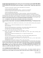
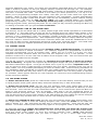
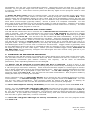
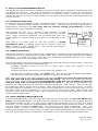
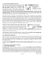
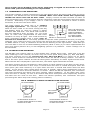
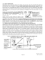
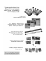
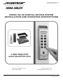
ASSA ABLOY, the global leader in door opening solutions MODEL DK-26 DIGITAL KEYPAD SYSTEM INSTALLATION AND OPERATING INSTRUCTIONS Securitron Magnalock Corp. Tel 800.624.5625 © Copyright, 2011, all rights reserved www.securitron.com [email protected] PN# 500-16900 Rev. D, 12/11 Securitron Magnalock Corp. Tel 800.624.5625 www.securitron.com [email protected] ASSA ABLOY, the global leader in door opening solutions SECURITRON MODEL DK-26 DIGITAL KEYPAD TABLE OF CONTENTS AND GUIDE TO THIS MANUAL SECTION 1. DESCRIPTION -------------------------------------------------------------Page 2 SECTION 2. PHYSICAL INSTALLATION ----------------------------------------------Page 2 SECTION 3. WIRING --------------------------------------------------------------------Page 2 SECTION 3.1 POWER SELECTION -----------------------------------------------------Page 2 SECTION 3.2 CONNECTING THE KEYPAD CABLE TO THE CPU BOARD ----------Page 3 SECTION 3.3 POWER AND ELECTRIC LOCK WIRING-------------------------------Page 3 SECTION 3.3.1 AC LOCK WITH AC POWER ------------------------------------------Page 3 SECTION 3.3.2 DC LOCK WITH AC POWER ------------------------------------------Page 4 SECTION 3.3.3 DC LOCK WITH DC POWER ------------------------------------------Page 5 SECTION 3.4 USE OF THE “F” TERMINAL --------------------------------------------Page 6 SECTION 3.5 ADDING OTHER LOCK CONTROL SWITCHES ------------------------Page 6 SECTION 3.6 THE REX FUNCTION -----------------------------------------------------Page 6 SECTION 4. PROGRAMMING -----------------------------------------------------------Page 8 SECTION 4.1 FIXED PROGRAMMING -------------------------------------------------Page 8 SECTION 4.2 KEYPAD CHANGEABLE PROGRAMMING------------------------------Page 9 SECTION 4.2.1 CHANGING THE USER AND PROG. CODE FROM KEYPAD -------Page 10 SECTION 4.2.2. ADDING MULTIPLE USER CODES ----------------------------------Page 10 SECTION 4.3 “MASTERKEY” USE OF THE HARD CODE -----------------------------Page 11 SECTION 4.4 SUBSET CODES ----------------------------------------------------------Page 11 SECTION 4.5 DELETING CODES -------------------------------------------------------Page 11 SECTION 4.6 SETTING THE TIME RANGE AND TOGGLE MODE -------------------Page 12 SECTION 5. CHANGING LED AND BEEPER OPERATION ---------------------------Page 12 SECTION 6 USE OF THE PROGRAMMABLE RELAY ----------------------------------Page 13 SECTION 6.1 DOORBELL FUNCTION --------------------------------------------------Page 13 SECTION 6.2 DURESS FUNCTION -----------------------------------------------------Page 13 SECTION 6.3 ANTI-TAMPER ALARM FUNCTION ------------------------------------Page 13 SECTION 6.4 DOOR PROP ALARM FUNCTION ---------------------------------------Page 14 SECTION 6.5 NIGHTLIGHT FUNCTION -----------------------------------------------Page 14 SECTION 7 ADDITIONAL HARD WIRED OPTIONS----------------------------------Page 14 SECTION 7.1 DUAL PAD OPERATION -------------------------------------------------Page 14 SECTION 7.2. HARD WIRED CODE DISABLING -------------------------------------Page 15 SECTION 7.3 ALARM SYSTEM SHUNTING--------------------------------------------Page 15 SECTION 7.4 ANTI-TAILGATING ------------------------------------------------------Page 16 SECTION 7.5 WIRING WITH TOUCH SENSE BAR AND MAGNALOCK ------------Page 16 APPENDIX A COMMAND SUMMARY----------------------------------------------------Page 17 APPENDIX B TROUBLE SHOOTING ----------------------------------------------------Page 17 MAGNACARE WARRANTY -----------------------------------------------Page 21 © Copyright, 2011, all rights reserved Page 1 PN# 500-16900 Rev. D, 12/11 SECURITRON MODEL DK-26 DIGITAL KEYPAD INSTALLATION & OPERATING INSTRUCTIONS 1. DESCRIPTION Securitron's DK-26 is a digital keypad system designed for medium/high security control of electric locks. It consists of two components: the keypad and the CPU board connected by a 16 ft. cable. This allows the CPU board to be mounted within the protected area for higher security. Tampering with or even destroying the keypad will not release the door. The rugged stainless steel keypad may be mounted outdoors in any environment as it is fully weatherproof. The keypad features true 10 digit operation (keys are not paired), three LED’s and a beeper. 2. PHYSICAL INSTALLATION The keypad is normally surface mounted on the outside of the door to be controlled, and the CPU Board is mounted inside the protected area safe from tampering. To install the keypad, holes must be drilled for the 2 mounting screws and the cable. A template is not provided due to unavoidable variations on the cable exit of each keypad. Referring to Figure 1, note that the top screw engages the slot at the top of the keypad. Once the top screw has been installed, the location of the cable hole should be set roughly by positioning the keypad and marking the cable hole point. Make sure the keypad is pulled down firmly on to the screw. A 3/8" (10MM) hole is then drilled for the cable. After the cable has been pulled through, the final screw secures the keypad to the wall. Note finally that a blank rectangular label has also been furnished. This can be used to cover up the “BELL” legend if you don’t intend to utilize the doorbell function. FIG. 1: PHYSICAL INSTALLATION OF KEYPAD (1) MOUNT SCREW TO ENGAGE SLOT AT TOP OF KEYPAD DRILL 1/8" (3MM) HOLE MOUNTING SURFACE CABLE (2) DRILL 3/8" (10MM) HOLE FOR CABLE (3) SECURE BOTTOM WITH SECOND SCREW. COVER SCREW HEAD WITH "DK-26" LABEL. DRILL 1/8" (3MM) HOLE NOTE: CHOOSE PHILIPS OR SPANNER (TAMPER) HEAD SCREW The CPU Board must be installed in a dry location free of extremes of temperature and humidity. If the 16 ft., twelve conductor cable that is included is not of sufficient length, additional cabling can be spliced by the installer. However, a long cable run can give rise to electronic noise problems in certain environments. It should therefore be avoided where possible and in no case should cable length exceed 100 ft. (30 meters). 3. WIRING 3.1 POWER SELECTION The DK-26 operates on 12 to 24 volts AC or DC. Nearly all electric locks operate on voltage within this range, so the power supply you would normally utilize to operate the electric lock will also operate the DK-26. Power consumption of the DK-26 depends on voltage and is shown on the following chart: DK-26 POWER CONSUMPTION: 12 VOLTS 24 VOLTS RELAYS, LED’S, + BEEPER ON (MAX) 160 mA 190 mA Page 2 PN# 500-16900 Rev. D, 12/11 Be sure that your power source is of adequate capacity to operate both the lock and DK-26. If the installation is "under-powered", the voltage of the supply will drop rapidly when the lock is energized and this can crash the microprocessor. 3.2 CONNECTING THE KEYPAD CABLE TO THE CPU BOARD There are 12 color coded wires in the keypad cable. Refer to Figure 3 and connect each wire to the indicated terminal on the CPU Board. No other connections may be made to these terminals (except if two keypads are used with one CPU board). 3.3 POWER AND ELECTRIC LOCK WIRING The wiring scheme for electric lock control varies depending on the type of lock and the desired control. The following sections provide drawings and explanations for different types. Note that the DK-26 includes additional options which are covered in Sections 6 and 7. Note installation of the MOV across the power wires to the lock. The MOV is the black disk shaped component furnished loose with the DK-26. Its function is to absorb inductive kickback from the lock’s coil. Without the MOV, this kickback voltage will arc over the relay contacts and reduce the switching life of the relay. The arc also creates electronic noise which could cause the microprocessor to malfunction. The MOV should be spliced into the lock power wires as close to the lock as possible. Some DC electric locks have internal kickback protection including all Securitron Magnalocks. You don’t need the MOV for these locks but if you are not sure, it does no harm to install the MOV so long as the lock power is in the 12-24 volt range. 3.3.1 AC LOCK WITH AC POWER A fail secure lock operating on AC is used. This is generally an electric strike. “Fail secure” means that the lock is secure when it is not powered. Power is applied to release the lock. Referring to figure 2, select a transformer of the same output voltage as the lock (12 or 24 VAC). Make sure the capacity of the transformer is large enough to operate both the DK-26 and the lock and that the transformer is UL listed under the UL 294 standard. The two transformer secondary wires connect to the “AC input” terminals as shown (there is no polarity with AC). Power from one terminal then goes to the common of relay #1. The NO contact of relay #1 will power the lock (releasing the door) when a correct code is entered. Note that AC locks are normally all fail secure. If you come across a fail safe AC lock (secure when powered) you would merely make the connection to the lock from the NC1 rather than NO1 terminal. FIG. 2: AC LOCK - AC POWER WIRING AC TRANSFORMER IN 12 OR 24 VAC F DC IN /OUT + NC1 C1 NO1 MOV Page 3 AC FAIL SECURE LOCK PN# 500-16900 Rev. D, 12/11 FIG. 3: OVERVIEW OF CPU BOARD KEYPAD CABLE BROWN GRAY BLACK WHITE BLUE RED KEYS KEYS KEYS KEYS COMMON BEEPER RED LED GRN YEL BEIGE KEYS GRN LED ORANGE KEYS GREEN PINK KEYS YELLOW YEL LED VIOLET RED BLU WHT BLK GRY BRN BGE ORG PNK VIO PS3 PS2 PS1 AC 12/24 AC POWER MICROPROCESSOR IN SPDT RELAY DISABLE HARD CODE REX UCD HCD NCX DISABLE ALL USER CODES PUSH TO PROGRAM HARD CODE SRC REX INPUT (REMOTE RELEASE) HARD CODE COM. FOR REX, UCD, HCD TERMS PRGM CODE PUSH TO SET PROGRAM MODE DC TERMINALS MAY ALSO BE USED AS OUTPUT TO POWER DC LOCK, IF AC POWER IS SUPPLIED + DC IN/OUT 12/24 DC NEGATIVE 12/24 DC POWER + AUX. SOCKET F FREE TERMINAL CX DPDT RELAY NOX NC2 PROGRAM RELAY CONTACTS C2 NO2 NC1 C1 NO1 LOCK CONTROL RELAY CONTACTS RELAY CONTACTS RATED AT 5 AMPS 3.3.2 DC LOCK WITH AC POWER For convenience and economy, most DC electric locks can be operated from an AC transformer when the DK-26 is used. Select a transformer of the same voltage as the lock (12 or 24). The CPU board converts the input AC to DC to operate the lock. Make sure the capacity of the transformer is large enough to operate both the DK-26 and the lock and that the transformer is UL listed under the UL 294 standard. The lock must accept full wave rectified DC power. This is true of most DC locks (including Securitron’s Magnalocks) but some specialty units require regulated DC power. You must operate those as described in the next Section. Note finally that many DC lock installations call for battery backup. To achieve this, you must employ a DC battery backup power supply and also follow the wiring description in Section 3.3.3. DC locks come in “fail secure” and “fail safe” versions. A fail secure lock is secure when not powered and a fail safe lock is secure when powered. All magnetic locks are fail safe. Figure 4 shows AC power being input to the AC terminals. The DC terminals furnish output power for Page 4 PN# 500-16900 Rev. D, 12/11 the lock. DC locks operated in this way must not draw more than 2 Amps. The positive DC terminal connects to the common of relay #1 and either the NO1 terminal (if the lock is fail secure) or the NC1 terminal (if the lock is fail safe) connects to the lock’s positive power input. This is shown in dotted lines. You only connect one of these terminals. Note that some DC locks are polarized and you must connect lock power correctly to positive and negative. Others are not polarized and can be connected either way. Consult the lock instructions. FIG. 4: DC LOCK - AC POWER WIRING AC TRANSFORMER IN 12 OR 24 VAC F DC IN /OUT NOTE: MOV NOT REQUIRED IF SECURITRON MAGNALOCK IS USED + NC1 C1 NO1 IF FAIL SAFE IF FAIL SECURE + DC FAIL SECURE OR FAIL SAFE LOCK MOV 3.3.3 DC LOCK WITH DC POWER Select a power supply of the same voltage as the lock (12 or 24). Make sure the capacity of the supply is large enough to operate both the DK-26 and the lock. The DK-26 does not require regulated power but certain specialized electric locks do, so follow the rule of matching the power supply to the requirements of the lock. DC locks come in “fail secure” and “fail safe” versions. A fail secure lock is secure when not powered and a fail safe lock is secure when powered. All magnetic locks are fail safe. Figure 5 shows correct wiring. The positive DC terminal connects to the common of relay #1 and either the NO1 terminal (if the lock is fail secure) or the NC1 terminal (if the lock is fail safe) connects to the lock’s positive power input. This is shown in dotted lines. You only connect one of these two terminals. Note that some DC locks are polarized and you must be sure to connect the lock power wires correctly to positive and negative. Others are not polarized and it doesn’t matter which way they are connected. Consult the lock instructions. FIG 5: DC LOCK - DC POWER WIRING AC IN F + + DC IN /OUT POWER SUPPLY NOTE: MOV NOT REQUIRED IF SECURITRON MAGNALOCK IS USED 12 OR 24 VDC NC1 C1 DC POWER NEED NOT BE REGULATED NO1 IF FAIL SAFE Page 5 IF FAIL SECURE + DC FAIL SECURE OR FAIL SAFE LOCK MOV PN# 500-16900 Rev. D, 12/11 3.4 USE OF THE “F” TERMINAL AC FIRE ALARM The F terminal on the power strip is not connected to CONTACTS anything. It is a free terminal with either of two TRANSintended uses. First, on some complicated NC FORMER installations, a large number of wires (generally DC C negative) may require termination. It can be convenient to run a jumper from the DC- terminal to WHEN THE FIRE the F terminal so that the large number of negative ALARM CONTACTS returns can be spread on to the two terminals. OPEN, ALL POWER Second, some magnetic lock installations require + WILL BE REMOVED interface with NC contacts controlled by the fire alarm FROM THE DOOR system which will cut low voltage power immediately releasing the magnetic lock for safety. The connection to the fire alarm contacts is normally made in the power supply but if you are using a plug in power supply, you’ll want to make the connection on the DK-26 CPU board where you have terminals. Using the example of a plug in AC transformer. See the drawing to the right. IN F DC IN /OUT 3.5 ADDING OTHER LOCK CONTROL SWITCHES The drawings in Section 3.3 are valid for simple installations where the DK-26 is the only control device that can release the electric lock. Often, however, additional control devices are called for. The most common is some type of exit switch and this issue is covered in the next Section. Sometimes other control switches are needed which are not appropriate for the REX input as use of this input triggers the timed release capability of the DK-26. A typical example would be a switch located centrally which would release the lock in response to an intercom call for example. If the lock is fail safe, the switch will need to break power to the lock and if it’s fail secure, the switch will need to send power to the lock. Figure 6 shows how to add external contacts for non timed remote release of the lock for both lock types. FIG. 6: ADDING EXTERNAL CONTACTS FOR FAIL SAFE AND FAIL SECURE LOCKS AC AC F F C + NC1 C1 + MOV DC IN /OUT DC IN /OUT NC IN IN + FOR NON-TIMED REMOTE RELEASE OF FAIL SAFE LOCK, PLACE NC CONTACTS IN CIRCUIT AS SHOWN FOR NON-TIMED REMOTE RELEASE OF FAIL SECURE LOCK, PLACE NO CONTACTS IN CIRCUIT AS SHOWN NO C C1 FAIL SAFE LOCK NO1 + FAIL SECURE MOV LOCK 3.6 THE REX FUNCTION AN N.O. SWITCH Often, when the DK-26 is used, provision must be made to allow SRC REX CLOSING BETWEEN people to use the door freely from the inside. If an electric strike "SRC" AND "REX" is used, exit may be accomplished by purely mechanical means CAUSES TIMED (turning the doorknob). If, on the other hand, a solenoid RELEASE OF THE operated or electromagnetic lock is used, free exit is only DOOR. possible if a switch on the inside releases the lock. Connection of this switch or switches is most easily accomplished by using the DK-26's REX input terminal (see Figure 2). REX stands for Request To Exit. When a normally open switch activates the REX terminal, the DK-26's control relay will open the lock for the amount of time programmed into the DK-26's timer. The result is the same as if the DK-26 was used from the outside of the door. The REX terminal is activated by being connected to the SRC (voltage source) terminal. It will also activate if +12 or +24V is input to the terminal from the DK-26’s external power supply. The drawing to the right shows the simplest connection to an external normally open momentary switch. Any number of additional switches could be connected in parallel so that pressing any of them would activate the REX function. Page 6 PN# 500-16900 Rev. D, 12/11 There are some special characteristics as to how the REX input works. First, it does not start the timer when the input is closed but rather when it reopens. This means that you can use the REX input to release the door for an extended period of time. As long as terminals REX and SRC remain connected, the lock will be released. When they disconnect, the lock will remain released for the amount of time programmed. The REX input is also retriggerable. This means that if the lock has been released and the REX input is triggered, the release time will be extended to the full value that has been programmed. When using exit switches, the possibility must be considered that an electronic failure may occur to the DK-26 and a person will not be able to exit. If the DK-26 controls the only door exiting the area, additional steps should be taken to improve the reliability of exiting so as to avoid trapping someone. This can most easily be done by implementing a secondary means of releasing the lock not dependent on the DK-26's REX input. Additional switch contacts should be used which directly control the electric lock. In the case of a fail-safe lock, which should always be employed when there is only one exit path, this can be easily accomplished with "double break" wiring between the exit button, electric lock, and DK-26. If the exit button has a set of normally open and normally closed contacts, it should then be wired according to Figure 6. When the exit button is depressed, its normally closed contacts directly break power to the lock while its normally open contacts activate the DK-26. In effect, the lock is released twice. Note that the NC contacts are placed in the circuit before the DK-26's lock control relay. This is to aid possible troubleshooting. It is usually easier to get to the DK-26 CPU board than to get to the push button wiring in a service situation. With wiring as shown in Figure 6, the push button NC contacts can be metered on the DK-26 CPU board. If for any reason a failure occurs with the DK-26, a person can still exit by holding the exit button down while pushing the door open. Note, you should always consult your local building or fire department when securing doors that are part on an emergency exit path to make sure you are complying with local codes. FIG. 7: DOUBLE BREAK WIRING FOR FREE EGRESS (TWO POLE SWITCH) AC IN NC NO NO F NC DC IN/OUT + CPU BOARD 2 POLE SWITCH SRC REX NC1 + MOV FAIL SAFE ELECTRIC LOCK C1 WHEN THE EXIT SWITCH IS ACTIVATED, THE NC CONTACTS OPEN WHICH RELEASES THE FAIL SAFE LOCK. AT THE SAME TIME, THE NO CONTACTS CLOSE WHICH ACTIVATES THE REX INPUT. THIS DEENERGIZES THE LOCK CONTROL RELAY WHICH RELEASES THE LOCK "A SECOND TIME" FOR THE AMOUNT OF TIME THAT HAS BEEN PROGRAMMED. IF THE DK-26 SUFFERS A FAILURE, THE EXIT SWITCH CAN STILL RELEASE THE LOCK FOR SAFETY. Note that Figure 6 shows a DC fail safe lock (virtually all fail safe locks are DC). Power could either be furnished by an AC transformer which would connect to the “AC IN” terminals or a DC power supply which would connect to the “DC IN/OUT” terminals. If you have an SPDT exit switch available to double break REX, the connection is shown in Figure 7. The difference is that you don’t use the SRC terminal at all. The REX terminal is triggered from the +DC terminal via the NO contact of the SPDT switch. Page 7 PN# 500-16900 Rev. D, 12/11 FIG. 8: DOUBLE BREAK WIRING FOR FREE EGRESS (SPDT SWITCH) AC IN NC F DC IN/OUT + C + NO CPU BOARD SPDT SWITCH REX NC1 MOV FAIL SAFE ELECTRIC LOCK C1 WHEN THE EXIT SWITCH IS ACTIVATED, THE NC CONTACTS OPEN WHICH RELEASES THE FAIL SAFE LOCK. AT THE SAME TIME, THE NO CONTACT DIRECTLY ACTIVATES THE REX INPUT. THIS DEENERGIZES THE LOCK CONTROL RELAY WHICH RELEASES THE LOCK "A SECOND TIME" FOR THE AMOUNT OF TIME THAT HAS BEEN PROGRAMMED. IF THE DK-26 SUFFERS A FAILURE, THE EXIT SWITCH CAN STILL RELEASE THE LOCK FOR SAFETY. 4. PROGRAMMING The DK-26 has ten numbered keys and a bell key which is used for several functions. Each of these keys is read separately by the unit, so the DK-26 is a true 11 digit access device. This provides excellent security against a code being guessed. Also, the DK-26 employs non-volatile EEPROM memory so that all programming is retained in a power failure. Before learning all programming options for the DK-26, you should decide how you want the unit to be used. Then learn only the appropriate programming for that use. This simplifies the task of operating the unit and cuts down on unneeded service calls. The programming questions to ask are: do you want a “fixed” code that will either never be changed or changed only rarely? Or do you want regular code changes from the keypad? This issue depends on the amount of security called for in the application. Finally, do you want multiple codes? The DK-26 supports 59. The purpose of multiple codes is to assign different codes to individuals or groups. Then if a code needs to be changed, the other individuals or groups need not go to the trouble of learning a new code. This is a convenience issue. 4.1 FIXED PROGRAMMING Employ fixed programming in a situation where the end user is not likely to ever change the code, or at least that changes would be rare. Fixed programming can be used in lower security "traffic control" applications, as the longer the code remains unchanged, the greater the risk that an unauthorized person will be able to learn it. The DK-26 makes it simple for you to program the unit in this “fixed” way. You will utilize a push button set, single code called the “Hard code”. With power applied to the unit, note that the yellow LED is on steadily. This signals that all code memories are empty. This is important as you don’t want any unknown codes present in the unit. If the yellow LED is not on, read the last two paragraphs in this section now for the procedure to erase existing codes. Do not pause while you’re entering the code as any time there is more than a five second gap between keys being pressed, the unit will stop reading the sequence. Note that a successful button press is echoed by a beep and a flash of the green LED. Page 8 PN# 500-16900 Rev. D, 12/11 Below we show a step by step summary. Power up unit; confirm steady yellow LED Press the “Hard Code” button on the CPU board for one second Confirm slow flashing yellow LED Within 30 seconds of pressing Hard Code button, enter a 2-7 digit code Wait 5 seconds Note two red LED flashes for confirmation Re-enter code (door should open) As mentioned at the beginning of this section, here is the procedure to follow if you don’t get a steady yellow light on power up. The absence of the yellow light means that for any reason, the unit already has one or more codes in memory. You must erase these other codes to be certain that the unit will operate only on the single code you plan to enter. Follow the steps shown below. Press the “Prgm Code” button on the CPU board for one second. Confirm fast flashing yellow LED Enter 0-0 followed by the Bell key (or wait 5 seconds). Confirm two red flashes Enter 8-8 followed by the Bell key (or wait 5 seconds). Confirm two red flashes Extinguish the fast yellow flashing LED by pressing the Bell Key or waiting 30 seconds This procedure has erased any program code that was present and all User codes. The yellow LED will usually come on steadily. If it doesn’t, it means that the unit has a previous Hard code in memory and this is no problem as you will be overwriting the old Hard code. Return to the beginning of this Section for fixed code programming. 4.2 KEYPAD CHANGEABLE PROGRAMMING In this application, two codes are programmed into the DK-26. The first, called the Program code acts as a password which allows changing the User code. It is the User code which is employed regularly to gain access. Knowledge of the Program code should be restricted to security management as its only use is to change the User code. With this method of operation, higher security is obtained because the end user can change the User code regularly or any time he feels it has been compromised. With power applied to the unit, note that the yellow LED is on steadily. This signals that all code memories are empty (you don’t want any unknown codes present). If the yellow LED is not on, read the last two paragraphs in this section for the procedure to erase existing codes. Below we show a step by step summary of programming the two codes. Power up unit; confirm steady yellow LED Press the “Prgm Code” button on the CPU board for one second Confirm rapid flashing yellow LED Within 30 seconds of pressing Prgm Code button, enter prefix 0-0 followed immediately by a 5-7 digit Program code Wait 5 seconds Note two red LED flashes for confirmation, note rapid yellow flashing LED returns Enter prefix 0-1 followed immediately by a 2-7 digit User code Wait 5 seconds Note two red LED flashes for confirmation, note rapid yellow flashing LED returns Press Bell key to terminate program mode or wait 30 seconds Re-enter User code (door should open) Re-enter Program code followed by the Bell key (yellow LED should rapidly flash), terminate with Bell key Page 9 PN# 500-16900 Rev. D, 12/11 As mentioned at the beginning of this section, here is the procedure to follow if you don’t get a steady yellow light on power up. The absence of the yellow light means that for any reason, the unit already has one or more codes in memory. You must erase these other codes to be certain that the unit will operate only on the codes you plan to enter. Follow the steps shown below. Press the “Hard Code” button on the CPU board for one second. Confirm slow flashing yellow LED Press the Bell key (yellow flashing stops). Confirm two red flashes Press the “Prgm Code” button on the CPU board for one second. Confirm fast flashing yellow LED Enter 8-8 followed by the Bell key (or wait 5 seconds). Confirm two red flashes Extinguish the fast yellow flashing LED by pressing the Bell Key or waiting 30 seconds This procedure has erased any Hard code that was present (see Section 4.1) and all user codes. The yellow LED will usually come on steadily. If it doesn’t, it means that the unit has a previous Program code in memory and this is no problem as you will be overwriting the old Program code. Return to the beginning of this section for keypad changeable programming. 4.2.1 CHANGING THE USER AND PROGRAM CODE FROM THE KEYPAD This is the day to day procedure that should be taught to the end user. Normally the end user will not access the CPU board. Everything should be done from the keypad. To change the User code: Enter program code, followed by the Bell Key, note rapid yellow flashing LED (program mode) Enter prefix 0-1 followed immediately by a new 2-7 digit User code Wait 5 seconds Note two red LED flashes for confirmation, note rapid yellow flashing LED returns Press Bell key to terminate program mode or wait 30 seconds Re-enter new User code (door should open) The program code should need changing much less often. To do it: Enter old program code followed by the Bell Key, note rapid yellow flashing LED (program mode) Enter prefix 0-0 followed immediately by a 5-7 digit new Program code Wait 5 seconds Note two red LED flashes for confirmation, note rapid yellow flashing LED returns Press Bell key to terminate program mode or wait 30 seconds Re-enter new Program code followed by the Bell Key (to test it), note rapid yellow flashing LED returns Press Bell key to terminate program mode or wait 30 seconds The logic behind this procedure is as follows. All programming for the DK-26 starts with putting the unit into program mode (except entering the single Hard code). The unit is put into program mode by either pressing the “Prgm Code” button on the CPU board or entering a valid program code. When you enter a program code, however, you have to terminate the sequence with the Bell Key. This is for a little extra security. An unauthorized person who came across a copy of the Program code might not know he had to press the Bell key after entering it. The prefix 0-0 causes the code which follows to be stored as the Program code. The prefix 0-1 causes the code to be stored as a user code. 4.2.2 ADDING MULTIPLE USER CODES The DK-26 has memory locations for up to 59 User codes. This allows separate codes for individuals or groups which is a benefit because when one code is changed (usually owing to a security worry), the people who use the other codes don’t have to learn a new code. To Page 10 PN# 500-16900 Rev. D, 12/11 program additional User codes, you follow the procedures described above for setting the User code in memory location 01 but you employ memory locations 02 through 59. For example, once the unit is in program mode (rapid yellow flash), entering 0-2 followed by a code sequence will enter a second User code. The same is true when you enter prefixes 0-3, 0-4 up to 5-9. When you’re programming multiple User codes, note that you can enter them one right after another. When a code is accepted, the unit signals by two red flashes. It then automatically goes back into program mode and another code can be immediately entered without exiting program mode. Be sure to test all the codes you have entered before you consider programming complete. You can individually erase any code (including the Program code) by entering program mode, pressing the prefix for the code (01-59) and then pressing the Bell key or waiting 5 seconds until you get the two red flashes. 4.3 “MASTERKEY” USE OF THE HARD CODE The primary use for the Hard code is to allow simple single code “fixed” operation as is described in Section 4.1. The Hard code can only be set or changed from the “Hard Code” button in the CPU board. It is deliberately kept separate from all programming functions. Another use for it, however, is as a “masterkey” code. For example, consider a facility with multiple DK-26’s under the control of different departments. Each department might want to employ different Program and User codes to restrict cross access but a common Hard code could be established for all of the units so that security management personnel could enjoy universal access. This Hard code will never be lost from keypad operations (the CPU board has to be accessed). 4.4 SUBSET CODES When you recognize that the DK-26 accepts multiple codes of different lengths, it is possible that one code will be a subset of another. For example, suppose you programmed “1-3-3-5-8” and then programmed “3-3-5” as another code. When you try to enter 1-3-3-5-8, you can’t complete the entry because when the unit sees the sequence 3-3-5, it will operate. A real problem could occur if a User code was a subset of the Program code. The unit could not be put into program mode from the keypad. The DK-26, however, avoids this problem by rejecting any code that is a subset of another code in memory. It signals this rejection by showing the single red (error) flash instead of the two-flash confirmation signal. You’ll get the same error if you try to enter a duplicate code. If you are trying to enter a code and see it rejected by the error signal, carefully check your list of other codes. You are probably attempting to enter a subset code. If the security procedures of the installation allow individuals to choose their own codes without reference to a list, the users need to be advised that they may have to try alternate codes if the one they prefer is rejected as a subset. Other typical reasons for code rejection are covered in the troubleshooting section at the end of the manual. 4.5 DELETING CODES To delete the Hard code, press the “Hard Code” button on the CPU board, confirm that you are in hard program mode (slow yellow flash) and press the Bell key or wait 30 seconds. To delete the Program code, put the unit into program mode (fast yellow flash) from the “Prgm Code” button or from the existing Program code. Enter 0-0 and press the Bell key or wait five seconds. You’ll see the two red confirmation flashes. You’ll need to then press the Bell key again to exit program mode or wait 30 seconds. Note that it can be considered logical to operate without a Program code. It is more difficult to put the unit into program mode (it can only be done from the “Prgm Code” button in the CPU board) but User codes can still be changed and some users may feel that this is a more secure code changing procedure. To delete any individual User code, put the unit into program mode (fast yellow flash) from the “Prgm Code” button or from the existing Program code. Enter the prefix for the code you wish to delete (01 - 59) and press the Bell key or wait five seconds. You’ll see the two red flashes. You’ll then need to press the Bell key again to exit program mode or wait 30 seconds. An alternate method to delete any individual User code when you know the actual code but not the two digit prefix is as follows. Put the unit into program mode (fast yellow flash) from the “Prgm Code” button or from the existing Program code. Enter 7-9 followed immediately by the complete code you wish to delete. If it’s a seven digit code you’ll Page 11 PN# 500-16900 Rev. D, 12/11 immediately see the two red confirmation flashes. Otherwise press the Bell key or wait five seconds. If you get the single red error flash, it is probably because the code you thought was in memory was not. You’ll then need to press the Bell key again to exit program mode or wait 30 seconds. To delete all User codes, there is a special prefix. Put the unit into program mode (fast yellow flash) from the “Prgm Code” button or from the existing Program code and enter 8-8. This special prefix will immediately delete all User codes and you’ll immediately receive the two red flashes. There is no need to hit the Bell key as it is used for early termination of sequences that don’t have a fixed length (typically codes). 8-8 as a prefix is a complete command. You will then need to press the Bell key to exit program mode (or wait 30 seconds). Deletion of all codes is typically done when you have lost accurate knowledge of what codes are in memory. It’s best to delete them all and program a new set. 4.6 SETTING THE TIME RANGE AND TOGGLE MODE The DK-26 will release the lock it controls for a default time of 5 seconds when a correct User code is entered. This can be changed to any value from 1-99 seconds by entering a special programming sequence. With the unit in program mode, enter key 9 followed by any two digit entry from 01 to 99. You will then see the double red flash immediately. If you get the single “error” flash, you probably entered only one digit. Then exit program by hitting the Bell key or waiting 30 seconds. Enter a correct User code to test that the changed time is working. The DK-26 will operate in toggle mode if key 9 followed by 00 is entered when the unit is in program mode. In toggle mode operation, the relay will energize when a correct code is entered and deenergize when a correct code is entered a second time. Toggle mode is generally used for the application where the door is released all day by entering a User code and then secured all night by entering a User code again. When you have enabled toggle mode, activation of the REX input will successively energize and deenergize the lock control relay (just as if you entered the User code). 5. CHANGING LED AND BEEPER OPERATION As delivered, the DK-26 echoes key presses by a short beep and a short flash of the green LED. The red LED comes on to show that the door has been released and also to confirm or reject programming commands (two flashes confirm; one rejects). As an issue of individual preference, these operating defaults can be changed. The beeper can be assigned to sound when the door is released. If this is done, it will continue to sound for its other functions (echoing keys and continuously sounding for 30 seconds if 16 wrong keys have been entered). Users find this function helpful if a silent type of electric lock is being employed (such as an electromagnetic lock). When the person attempting to enter hears the beeper, he is prompted to open the door. To set this change, put the unit into program mode and enter 7-0. You will see the two flash confirmation. Exit program mode by hitting the Bell key or waiting 30 seconds. Some customers want to silence the beeper as its sound can be considered annoying in some environments. . To set this change, put the unit into program mode and enter 7-1. You will see the two flash confirmation. Exit program mode by hitting the Bell key or waiting 30 seconds. This function will override the one discussed in the previous paragraph. To return the beeper to factory set default, put the unit into program mode and enter 7-2. Finally, you can reverse the red/green LED logic so that the green light comes on when the red light did, and visa versa. To set this change, put the unit into program mode and enter 73. You will see the two flash confirmation. Exit program mode by hitting the Bell key or waiting 30 seconds. If you make this change, note that every time this manual discusses something that the red or green LED does, it will be reversed. To return the red/green LED logic to factory set default, put the unit into program mode and enter 7-4. Page 12 PN# 500-16900 Rev. D, 12/11 6. USE OF THE PROGRAMMABLE RELAY The DK-26 CPU board includes a second relay whose 5 Amp, SPDT contacts are marked CX, NCX and NOX (see Figure 2). This relay is employed for different functions which are selected by commands sent to the CPU board while the unit is in program mode. In general, you need to choose the function you want to make active for this relay (if any) and the following sections lay out the choices. 6.1 DOORBELL FUNCTION As delivered, the programmable relay will operate when the Bell key is pressed when the unit is in “normal” operating mode (ready to accept a code). The Bell key is used a great deal in programming operations but the relay will not operate during programming (including initiating and exiting programming mode). The purpose for this is to operate a real doorbell so that unauthorized persons outside the controlled door can request entry. Most commercial doorbells are furnished with their own power supply, so typical wiring is as shown in the drawing to the right. Note that if you don’t plan to use this function, a blank rectangular label is supplied which can be used to cover the “BELL” legend on the keypad face. This avoids misleading a person on the outside of the door. CX NOX DOORBELL POWER SUPPLY 6.2 DURESS FUNCTION The duress function is used for high security applications. It allows a person being threatened to release the door but simultaneously create a silent alarm which would be employed to summon assistance. To make this work, obviously the threatened authorized person has to enter something different than a standard User code. The DK-26 handles this requirement by establishing the Hard code as a duress code. You need to do several things however to implement this. Ordinary operation must be via one or more User codes (see Section 4.2 for programming) Program the Hard code as your duress code (see Section 4.1). Put the unit in program mode , and enter 7-5. You will see the two flash confirmation. Exit program mode by pressing the Bell key or waiting 30 seconds. Now, when you enter a user code, the door will open but when you enter the Hard code, the door will open and the programmable relay will switch. The door will remain open for the amount of time programmed but the programmable relay will stay switched (it latches) until the hard code is entered a second time to reset it. Use the programmable relay contacts (CX, NOX and NCX) to report the releasing of the door under duress. This can be done by interfacing with an alarm panel or dialer. Note that a duress code is rarely used. To make the code easier to remember, you can select a Hard code that is close to the User code (if only one User code is being employed) or you can select a short hard code. Note finally that selection of this option means you give up the opportunity to implement a doorbell or other use of the programmable relay. 6.3 ANTI-TAMPER ALARM FUNCTION A person attempting to guess the code and pressing 16 wrong digits will put the DK-26 into alarm. The keypad's beeper and green LED will operate for 30 seconds during which time the keypad will accept no input. For high security applications, particularly when a lot of User codes are active, you can assign the programmable relay to operate during the alarm period. Put the unit into program mode and enter 7-6. You will see the two flash confirmation. Then, exit program mode. You have now the means to report attempts to guess a valid code. This can be done by interfacing with an alarm panel or dialer. Note finally that selection of this option means you give up the opportunity to implement a doorbell or other use of the programmable relay. Page 13 PN# 500-16900 Rev. D, 12/11 6.4 DOOR PROP ALARM FUNCTION This function provides enhanced security at the door CONNECT A DOOR SRC UCD HCD SWITCH WHICH by creating an alarm signal any time the door is left OPENS WHEN THE open too long while being used for entry or exit. DOOR OPENS TO With the function enabled, select a relatively long UCD OR HCD door open time (see Section 4.5 to set timer). You DEPENDING ON WHICH will then need a door switch whose contacts open COMMAND YOU CHOOSE when the door opens. To wire the door switch, follow DOOR SWITCH the drawing to the right. You will give up the function of disabling either the Hard code or all the User codes (see Section 7.2). Put the unit into program mode and enter 8-2 to put this feature on the HCD terminal or 8-3 to put it on the UCD terminal. You will see the two flash confirmation. Then, exit program mode. The respective input terminal will have its meaning redefined. You will also give up the opportunity to implement a doorbell or other use of the programmable relay. Now, when a code is entered (or the REX input is used), the door will release for the relatively long period of time programmed. If the door is not opened at all, the lock will resecure when the set time expires and nothing further will happen. If the door is opened and recloses before the time expires, it will resecure immediately upon closure. This is called anti-tailgating and means that although you have selected a long release time, a second person will not be able to use the door after a first person has, because the door resecures immediately upon reclosure. If the door remains open for a longer period of time than is set on the timer, the programmable relay will switch and will remain energized until the door closes or the keypad is used again. Note that if you are using the programmable relay for another function you can enable antitailgating alone (no alarm signal) as is described in Section 7.4. DC IN /OUT AUDIBLE DOOR PROP ALARM Connection from the programmable relay is generally not made to an alarm system, as if an alarm system is active SONALERT on the door, you can get the same “door open too long” + signal more simply by using the second pole of the lock CX NOX control relay to shunt the door switch (see Section 7.3). Generally, you mount a Sonalert on the CPU board enclosure. It will sound if the door is left open too long and this will act as a prompt for someone near the door to close it. Sonalerts operate on 12-24 VDC so the wiring shown on the drawing to the right should be used. To terminate this function and return the HCD or UCD input to its standard use (and return the programmable relay to the doorbell function), put the unit into program mode and enter 8-4. You will see the two flash confirmation. Then, exit program mode. 6.5 NIGHTLIGHT FUNCTION When this function is selected, the act of touching any key will operate the programmable relay for five seconds. This may be used to turn on a lamp directed at the Keypad at night so that the person using the Keypad can see to enter the code. Put the unit into program mode and enter 7-7. You will see the two flash confirmation. Then, exit program mode. Note that selection of this option means you give up the opportunity to implement a doorbell or other use of the programmable relay. To return the programmable relay to factory set (doorbell) function, put the unit into program mode and enter 7-8. You will see the two flash confirmation. Then, exit program mode. 7. ADDITIONAL HARD WIRED OPTIONS 7.1 DUAL PAD OPERATION If keypad control from both sides of the door is desired, two keypads can be connected to one CPU Board. Simply put the colored wires from both keypads into the appropriate terminals on the CPU Board such that 2 wires are in each terminal. Either keypad will then be able to release the lock and both keypads will beep and illuminate their LED's when either one is used. Two is the maximum number of keypads that can be connected to one CPU Board. Note that in the unusual case where both keypads are being used simultaneously, the door will not release as the sequence will certainly be disturbed. Only one keypad may be used at a time. Be sure you Page 14 PN# 500-16900 Rev. D, 12/11 don’t violate egress building codes when employing a keypad on the inside of a door. Check with your local building or fire department. 7.2 HARDWIRED CODE DISABLING This means making a switch connection to the CPU board which will cause valid codes to not be accepted. The DK-26 has two terminals marked “HCD” and “UCD” which will respectively disable the Hard code and all User codes. Simply connect the SRC terminal to either of these terminals via an external switch and the respective codes will not function while the switch is closed. Alternately if you supply +12V or +24V from the DC+ terminal to either of these terminals, it will have the same effect. The main reason for doing this is to support SRC REX UCD HCD day/night operations. For example, you could allow all User codes to be active during the day WITH THE CONTACTS but disable them at night by closing a switch AS SHOWN, THE HARD between SRC and UCD. The Hard code would be NO CODE IS DISABLED. the only method of entry at night. Or, you could WHEN THEY SWITCH, NC C have no Hard code programmed so that there SPDT ALL USER CODES SWITCH would be no entry at night. This could be done by OR RELAY WILL BE DISABLED. timer controlled contacts from a timer such as Securitron’s model DT-7. It’s finally possible to flip the codes (Hard and all User) so that, for example, User codes are active only during the day and the Hard code is active only at night. An SPDT switch or relay is needed to do this as the drawing to the right shows. Note that you won’t be able to use one of these disabling features (Hard or User) if you have implemented the door prop alarm (Section 6.4) or anti-tailgating (Section 7.4) features. These reassign one of the terminals. 7.3 ALARM SYSTEM SHUNTING The DK-26's lock control relay is of the double pole, double throw type. Note that in all the other drawings in this manual, we show only one of the poles being used (C1, NC1 and NO1). The most common use for the second pole (C2, NC2 and NO2) is to shunt out an alarm system, which would be connected to the door when the DK-26 is being utilized. The idea is that if the door opens without the DK-26 having been activated, an alarm signal should result. When the DK-26 is employed to open the door, the alarm signal should be shunted. The alarm system will be connected to a door switch or other detector at the door via two wires. You will need to determine if this “loop” is closed when the door is closed and opens when the door opens (the most common) or is open when the door is closed and closes when the door opens. In the former case (closed when the door is closed), splice wires respectively from C2 and NO2 into the wires from the detector or switch. When the DK-26 operates, this connection will close preventing the alarm loop from opening (alarm condition). In the latter case (open when the door is closed), cut one of the alarm loop wires and splice wires respectively from C2 and NC2 into the ends of this wire. When the DK-26 operates, this connection will open preventing the alarm loop from closing (alarm condition). FIG 8 WIRING TO SHUNT ALARM SYSTEM ON DOOR TO ALARM PANEL TO ALARM PANEL NC2 C2 NO2 DOOR SWITCH NC2 C2 CUT EITHER WIRE FROM SWITCH ALARM SIGNAL WHICH IS CLOSED WHEN DOOR IS CLOSED; OPENS TO ALARM NO2 DOOR SWITCH ALARM SIGNAL WHICH IS OPEN WHEN DOOR IS CLOSED; CLOSES TO ALARM Page 15 PN# 500-16900 Rev. D, 12/11 7.4 ANTI-TAILGATING Particularly when using the longer time ranges, the end user may be concerned that after an authorized person has used the door, a second unauthorized person can also use it before the lock has reset. By the addition of a door switch which opens when the door opens, the DK26 can be made to re-engage the lock as soon as the door has re-closed regardless of the status of the timer. To implement this feature, a special command has to be sent to the CPU board which will alter the function of either the HCD or UCD input terminal. When you enable this antitailgating feature, you must give up the capability of disabling either the Hard code or all the User codes. Put the unit into program mode and enter 8-0 to assign this function to the HCD terminal or 81 to assign it to the UCD terminal. You will see the two flash confirmation. Then, exit program mode. SRC UCD HCD CONNECT A DOOR SWITCH WHICH OPENS WHEN THE DOOR OPENS TO UCD OR HCD DEPENDING ON WHICH COMMAND YOU CHOOSE Finally connect a door switch as shown in the DOOR SWITCH drawing to the right and you will see that the door will always relock immediately when it recloses regardless of how much time is left on the timer. The feature will operate when the door has been released from the keypad or from the REX input (see Section 3.6). Note that to disable the anti-tailgating feature and return full function to the HCD and UCD terminals, put the unit into program mode and enter 8-4. Note that the DK-26 supports a more powerful anti-tailgating feature which incorporates an alarm signal through the use of the programmable relay. Read Section 6.4 for details. 7.5 WIRING WITH SECURITRON'S TOUCH SENSE BAR AND MAGNALOCK The DK-26 is often used with Securitron's Touch Sense Bar and magnetic lock. The following drawing shows wiring for this particular configuration. Note that the REX input is not used. Since touching the bar opens the door in a single motion, you do not want to activate the DK26's timer which would only serve to keep the lock released for a longer time, thereby reducing security. Another potentially confusing element is that the Touch Sense Bar is also a powered device which operates most reliably when it is constantly powered. The drawing shows a wiring method that is applicable for either an AC or DC power supply (naturally, the supply voltage must be matched to the lock voltage). Note that a variation of this wiring scheme could be desired if you are using the second pole of the DK-26’s lock control relay to shunt an alarm system (see Section 7.3). You would then want the Touch Bar to operate the DK-26’s lock control relay in double break fashion so that the alarm system is shunted both for entry and exit. Simply follow Figure 9 except also connect the blue and orange wires from the Touch Sensor to terminals SRC and REX on the CPU board (as well as connecting the second pole of the lock control relay to the alarm point as shown in Section 7.3). FIG. 9: WIRING OF DK-26, TOUCH SENSE BAR AND MAGNALOCK NOTE: SEE FIG. 2 FOR 12 WIRE KEYPAD CABLE CONNECTIONS BLACK CPU BOARD GREEN F DC IN/OUT + + DC IN/OUT IN IF DC POWER IS BEING USED, CONNECT 12 OR 24 VDC TO DC IN/OUT TERMINALS. BE SURE TO OBSERVE POLARITY TOUCH RED SENSOR AC IF AC POWER IS BEING USED, CONNECT 12 OR 24 VAC TO AC IN TERMINALS WHITE RED MAGNALOCK NC1 C1 BLACK POWER SUPPLY VOLTAGE MUST MATCH VOLTAGE OF MAGNALOCK Page 16 PN# 500-16900 Rev. D, 12/11 APPENDIX A: COMMAND SUMMARY WITH THE UNIT IN PROGRAM MODE (FAST YELLOW FLASH): 00 followed by 5-7 digits sets Program code 01 followed by 2-7 digits set first User code 02-followed by 2-7 digits sets second User code Additional User codes can be set up to the prefix 59 (total 59 User codes) 70 will sound beeper when door is open (except toggle mode). Echo and prompt beeps are retained 71 will silence beeper at all times 72 will return beeper to factory set 73 will reverse light logic (red to echo, green to show door is open) 74 will return light logic to normal 75 will direct Hard code to programmable relay for duress (entering Hard code releases door and switches programmable relay) 76 will transfer programmable relay to alarm function (16 wrong digits switches programmable relay as well as locking out keypad for 30 seconds) 77 will transfer programmable relay to light function (relay operates for 5 seconds when any key is pressed.) 78 will return programmable relay to doorbell function. 79 is alternate code delete. Any valid code entered directly after the 79 command will be deleted 80 re-assigns the HCD terminal to anti-tailgating 81 re-assigns the UCD terminal to anti-tailgating 82 re-assigns the HCD terminal to door prop alarm 83 re-assigns the UCD terminal to door prop alarm (Note the door prop alarm function automatically includes anti-tailgating) 84 returns either input to original (code disable) meaning 88 will erase all user codes (not Program or Hard code) 89 will return all functions (including timer) to factory set. Codes are unchanged. Pressing 9 when in program mode sets the timer. Two digit codes must be entered from 01 to 99 seconds. Default is 5 seconds. Entering 00 sets toggle mode. APPENDIX B: TROUBLESHOOTING Note first that the DK-26 replaces older Securitron keypads: the DK-20, DK-20+ and DK-25. The DK-26 keypad and CPU board are not compatible with any of the older units so make sure you have both a DK-26 keypad and DK-26 CPU board. If the keypad label is missing, you can identify a DK-26 keypad by the fact that it has three LED’s. The DK-26 circuit board is marked with its name. Also, as you are going through these troubleshooting points, note that the goal is to get the unit working, but if this is not possible, to identify whether the failure is in the keypad or in the CPU board. PROBLEM-- Unit appears dead. First check that power has been correctly connected and use a voltmeter on the CPU board to make sure that the correct voltage level is present. If the voltage reads very low, the problem may be that a fail safe lock being controlled by the DK-26 is drawing too much current for the power supply. Remove the lock from the circuit. If this restores proper voltage and operation of the DK-26, you'll have to determine if the power supply is undersized or if there is a short circuit in the lock wiring which is pulling down the power supply. If the DK-26 is receiving specified voltage, briefly short terminal SRC to terminal REX. You should hear the relay click. This confirms that the CPU board is working but for some reason, it’s not reading the keys. Make sure that the keypad cable is connected exactly as shown in Figure 2. It is fairly easy to skip a terminal when connecting the keypad cable and also a strand of wire may jump between two terminals. Pay particular attention to the keypad white wire going into terminal WHT. If this wire is not connected, the keypad will appear to be dead. Page 17 PN# 500-16900 Rev. D, 12/11 PS3 PS2 PS1 AC IN If the relay doesn’t operate when SRC and REX are connected, the CPU board has either tripped one of its automatic fuses or has some major problem requiring replacement. The DK-26 employs three special type fuses called PolySwitches. PolySwitches look like capacitors. To identify them on the board note the drawing to the right. When a PolySwitch senses a current overload problem, it automatically adds a high resistance to the circuit which limits current flow to about 100 mA, thereby protecting the circuit. Each PolySwitch protects against a particular problem and you need to know how to determine if the PolySwitch has tripped and how to correct the problem and reset the PolySwitch. PolySwitch #1 comes into play only if you are powering the unit from an AC source connected to the AC input terminals. It protects against an internal short on the board in the components (four large diodes) that convert AC to DC. If you are powering the board with DC voltage into the DC input terminals, you can ignore PolySwitch #1. PolySwitch #2 protects against an internal DC short circuit on the CPU board. PolySwitch #3 protects against a short circuit in the keypad which can be caused by skinned keypad wires or mis-wiring the keypad cable into the CPU board terminals. PolySwitch #3 will also trip if there are short circuit problems with the SRC, REX, UCD and HCD terminals. To check the PolySwitches, apply the probes of a voltmeter to both PolySwitch leads. Note that you have to do this with power on the board. If you are checking PolySwitch #1, set your voltmeter to AC. Set it to DC for PolySwitches #2 and #3. In the normal condition, the PolySwitch will be conducting current so you will read less than one volt. A tripped PolySwitch acts as a high impedance resistor so you will read several volts across the PolySwitch leads. If none of the three PolySwitches have tripped but the properly powered board will not operate its relay when SRC and REX are briefly shorted together, the CPU board must be returned for replacement to the factory. Any time you find a tripped PolySwitch, you have to understand how to reset it. Overload current through the PolySwitch trips it so that it clamps the current down to roughly 100 mA. The PolySwitch will continue to clamp until all power is removed for about 5 seconds. It is not enough to correct the overload condition; you have to depower the board for 5 seconds and the PolySwitch will reset itself. If PolySwitch #1 has tripped, visually inspect the four large diodes on the board to see if a loose wire has fallen on them to create a short circuit. If you do not find such a physical problem that can be easily corrected, the board should be replaced although you should be aware that it can be operated with no problems from a DC power supply connected into the DC input terminals if only PolySwitch #1 has tripped. Read the special case paragraph below for another possible cause if you are using AC power to operate a DC lock. If PolySwitch #2 has tripped, and you are using DC power, make sure your input polarity is correct (see Figure 2). Reversing your input polarity will trip PolySwitch #2. Otherwise, look for any loose wires that could be creating a short circuit anywhere on the board. If you can’t correct the fault that is tripping PolySwitch #2, the board must be replaced. Read the special case paragraph below for another possible cause if you are using AC power to operate a DC lock. In the special case of AC power operating a DC lock (see Figure 4), a short circuit in the external lock or lock wiring will trip either PolySwitch #1 or #2 (but not both). Attempt to reset the PolySwitch after disconnecting the external lock to determine if this is the problem. If PolySwitch #3 has tripped, the overload condition is in the keypad wiring or in terminals SRC, REX, UCD and HCD. Carefully make sure that all keypad wires are connected to the correct terminals. If they are, temporarily disconnect the keypad and attempt to reset PolySwitch #3 by de-powering the board for 5 seconds. Once the board has been re-powered, momentarily connect SRC to REX to see if the board will function (the lock control relay will operate). If the CPU board resumes function, reconnect the keypad. If PolySwitch #3 trips again, the keypad will need to be replaced. If the CPU board did not resume function, disconnect any wires on the SRC, REX, UCD and HCD terminals and attempt reset. If this does not restore function to the board, the board will need to be replaced. Page 18 PN# 500-16900 Rev. D, 12/11 PROBLEM-- Keys do not operate but a beep is heard every five seconds This is a diagnostic feature which indicates that one of the keys is being read as down (always being pressed). In that condition, the CPU board will not be able to read any other keys. It can happen because of mechanical failure within the switch element such that the key really is down, or keypad wires that are shorted to each other. The latter problem usually happens when insulation is scraped off some of the wires in the keypad cable as it’s being pulled through the door frame. You may be able to restore operation by rapping on all the keys. If this works, however, it is likely only a temporary fix and you should be prepared to change the keypad. Next, check the wiring of the keypad cable into the board (see Figure 2). If you don’t see any problems, the keypad will need to be replaced but you can restore partial use, if you wish, while awaiting a replacement. Put the positive probe of a voltmeter on terminal WHT and successively apply the negative probe on terminals BLK, GRY, BRN, BGE, ORG, PNK, and VIO. “Good” terminals will read about 11 volts. Two terminals, however, will read about zero volts. Remove the wires from the two terminals which read zero volts. If you are wondering why a single down key does not create a single zero volt terminal read, you should understand that the keys are in a two of seven matrix so the one to one relationship doesn’t hold. When you remove the two wires from the zero volt reading terminals, you will disable several keys. You will be able to determine which keys are working by pressing each key and seeing which ones are echoed by a beep and LED flash. You can then establish a temporary Hard code using only the active keys by pressing the Hard Code button on the CPU board and following the instructions in Section 4.1. PROBLEM-- A key isn’t echoed (no beep or LED flash) This is the opposite of the above problem. A key is failing to be read when it is pressed. This can happen because of mechanical failure within the switch element such that the key will not close, or from a broken or mis-wired keypad wire. If, however, the problem is with a wire, more than one key will be “dead”. If just one key is not being echoed, the problem is with the key itself. You can, of course, use the unit for all operations that don’t require that particular key but you will want to replace the keypad for full operation. PROBLEM-- Unit beeps when keys are pressed but does not accept programming If the problem occurs on initial installation, usually it's caused by misunderstanding the programming instructions. Read them again carefully. Be sure you're not waiting more than 5 seconds between hitting keys as if you are, the entry will be ignored. Finally note that if terminals SRC and UCD are connected, all User codes will be disabled. If terminals SRC and HCD are connected, the Hard code will be disabled. PROBLEM-- Beeper doesn’t sound while the unit otherwise functions Note that the beeper could have been deliberately silenced by the unit having been sent a special command. Even on a new unit, this could have happened by factory error. Attempt to restore the beeper by putting the unit into program mode and entering 7-2. You should see the two red flash confirmation. If the beeper still doesn’t work, the problem is either a wiring mistake, a defective beeper or a fault on the CPU board with the output that drives the beeper. Check that the keypad blue wire (this controls the beeper) is connected into terminal BLU. If it is, next remove it from the BLU terminal and briefly touch it to terminal DC-. If the beeper sounds, the problem is with the beeper driver on the CPU board and the CPU board will have to be replaced. If the beeper does not sound, the problem is with the beeper itself in the keypad or with the internal beeper wiring within the keypad. The beeper is the only part of the keypad which is repairable. This is because the beeper is physically located in a chamber at the bottom of the keypad. If it was sealed in the keypad, the sound level would not be adequate. Look at the beeper in its chamber to confirm that the wires look OK. You can then return the keypad to the factory for beeper replacement or you can replace the beeper in the field (this requires soldering). The part number for a replacement beeper from Securitron is 050-10600. PROBLEM-- One or more of the LED’s do not work while the unit otherwise functions This is either a wiring mistake, a failed LED in the keypad or a fault on the CPU board with the output that drives the LED. Each LED is operated by the wire that bears the LED’s color. So, for example, if the green LED is the one that is not working, first check to see that the green keypad wire is correctly connected to terminal GRN. . If it is, next remove it from the GRN terminal and briefly touch it to terminal DC-. If the green LED comes on, the problem is with the driver on the CPU board and the CPU board will have to be replaced. If the LED does not Page 19 PN# 500-16900 Rev. D, 12/11 come on, the problem is with the LED in the keypad or with the internal wiring within the keypad. The keypad will have to be replaced to restore operation of the LED. PROBLEM-- Error signal (one second long red pulse) received while programming Anytime you receive an error signal, retry the programming operation. It’s easy to mis-hit one key. If the error signal persists, it is almost always a misunderstanding of programming procedures rather than a fault with the unit. A product fault that impaired the operation of the microprocessor would generally prevent it from giving you the error signal. When programming the hard code, you directly enter the code once you are in hard programming mode (slow yellow flash). Remember you must never pause for more than five seconds while pressing keys. The only way to get an error signal while programming the hard code is to enter an illegal one digit code. When in program mode, the most common error is to forget to enter the two digit memory slot prefix when attempting to program a code. Valid prefixes are 00-59 and if this step is forgotten in an attempt to enter the code directly, there are a lot of sequences that will create an error signal. For example, any sequence that starts with 6 will be rejected. 8-5 is also illegal. Or if you entered just 9-2, the unit would read 9 as an attempt to change the door open time and then reject a single digit new time. Another source of the error signal would be an illegal attempt to enter a program code of less than five digits (after prefix 0-0). Finally, while programming multiple codes, you will get an error signal if a code you’re attempting to program is a subset of one already in memory or a duplicate (see Section 4.4). PROBLEM-- Door opens on a short code that wasn’t programmed This can arise through an unnoticed programming error. Suppose you want to program 4-5-1-2. But when the unit is in program mode, you forget to put in the two digit memory slot prefix but just directly enter 4-5-1-2. The microprocessor will accept this sequence and interpret it as code 1-2 in memory slot 45. You test the code by re-entering 4-5-1-2 and the door opens because the sequence includes the real code, 1-2. Later it will be noticed that the door is opening on 1-2 as this is such a simple sequence that it will be entered. When you have any evidence that unknown codes (particularly short ones) are in the unit, it is best to erase all User codes and reprogram. PROBLEM-- How to check the Keypad For reference, when each key is pressed, two terminals will measure zero volts with respect to the WHT (common) terminal. You can use a voltmeter to see that each key is working correctly. Put the positive probe on WHT and when key #1 is pressed you will read roughly zero volts on VIO and BRN (the other terminals in the matrix will be reading about 11 volts. The terminal pair that will show zero volts for the other keys are as follows: #2 = VIO + GRY #3 = VIO + BLK #4 = PNK + BRN #5 = PNK + GRY #6 = PNK + BLK #7 = ORG + BRN #8 = ORG + GRY #9 = ORG + BLK #0 = BGE + GRY BELL=BGE +BLK PROBLEM-- Unusual operation complained of after some operating history "Unusual" operation can be caused by the microprocessor in the CPU Board being disturbed by electrical noise. Symptoms can vary quite a bit. The unit may forget its codes, the action of the keypad beeper may become drawn out or erratic, the timer may function at widely varying ranges, etc. To cure the problem, remove power from the CPU Board for about 10 seconds, then reconnect it. This forces the microprocessor to reset itself and reload its program. If the unit has functioned for a long period of time without incident, this may be an adequate fix. The problem may never reoccur and the end user should be made aware of this simple fix if it should reoccur. All microprocessors can sometimes "crash" and they are restored by reset. If, however, the problem is more persistent, steps can be taken to guard against electrical noise problems. You should make sure that the MOV furnished with the unit is properly installed across the electric lock (review Figures 3-5). The inductive kickback from electric locks can often be a source of considerable electrical noise. Noise can also come from the keypad cable, particularly if its length has been extended. There is no specific distance which is a limit for an extended keypad cable. Shorter is always better as cable noise varies with the proximity of Page 20 PN# 500-16900 Rev. D, 12/11 noise producing devices such as motors, fluorescent or neon lighting etc. The same problem can occur if the cable from an exit switch is extended a long way from the CPU board. If there are noise sources, it may be necessary to limit the cable run distances while also trying to avoid the noise sources. If the problem shows up frequently, it is usually bad power. This particularly occurs when a fail secure lock is operated from the same supply as the DK-26. When the lock is energized, it may draw too much power for the power source. This reduces the voltage and these voltage swings can crash the microprocessor. The solution is either to use a power supply with greater capacity or use two power supplies: one to operate the DK-26 and the second to operate the fail secure lock through the DK-26's lock control relay. IF THE PROBLEM PERSISTS CALL SECURITRON TOLL FREE: 1-800-MAG-LOCK MAGNACARE LIFETIME REPLACEMENT WARRANTY For warranty information visit www.securitron.com/en/site/securitron/About/MagnaCare-Warranty/ Page 21 PN# 500-16900 Rev. D, 12/11