1
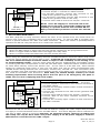
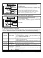
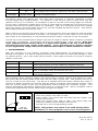
DC Power Supply 1234567 Fail-Safe DC Electric Lock DK-12 Back Side R NC C NO SPDT Switch Double Break Wiring For Free Egress (SPDT): Connect DC supply to ‘AC/DC+’ and ‘AC/DC-’ terminals. Connect ‘AC/DC+’ terminal to the common terminal of the SPDT switch. Connect the normally closed contact of the SPDT switch to the ‘COM’ terminal. Connect the normally open contact of the SPDT switch to the ‘REX” terminal through resistor (R). Connect ‘NC’ terminal to the positive lead of lock. Connect other lead of lock to the ‘AC/DC-’ terminal. NOTE: Resistor (R) is 3300 ohms, ½ watt. 5. WIRING WITH SECUTITRON’S TOUCH SENSE BAR AND MAGNALOCK Power Supply Red 1234567 Magnalock Black Black Red White Green Touch Sense Bar Touch Sense Bar and Magnalock Wiring: Connect supply to ‘AC/DC+’ and ‘AC/DC-’ terminals. Connect ‘AC/DC+’ terminal to the red and white wires of the Touch Sense Bar. Connect ‘AC/DC-’ terminal to the black wires of both the Touch Sense Bar and the Magnalock. Connect ‘NC’ terminal to the red lead of the Magnalock. Connect ‘COM’ terminal to the green lead of the Touch Sense Bar. DK-12 Back Side 6. FEEDBACK AND ENTRY OVERVIEW The DK-12 comes with indictor lights above the keypad; left-hand side green, center yellow, and right-hand side red. These three indictor lights, and the backlight, provide feedback during operation. Note that the green and red LEDs could be reversed thru programming. INDICATOR ACTION Red Light Single Flash Red Light Double Flash Red Light Continuous Flashing Red Light Continuously On Yellow Light Continuous Flashing Yellow Light Green Light Continuously On Single Flash MEANING While in programming mode an error was made during program entry; or The program entry was correct but the DK-12 can not accept the programming, for example a code was trying to be set that is a subset of another code; or A 5 second timeout occurred at any time during a programming step. While in programming mode a confirmation that a valid program entry was made; or During normal operation the DK-12 was put into or taken out of lockout mode. During normal operation the relay is energized while the DK-12 is in relay timer mode; flashes once per second. While in normal operation the DK-12 is in passage mode; or The DK-12 is in toggle mode and the relay is energized; or The REX input is being held active. While in programming mode the light will flash once per second; or While the ‘PCR’ jumper is in the ‘ON’ position the light will flash once per second. While in normal operation this indicates that there are no codes in memory. Key press detected. Page 3 PN# 500-24010 Rev. C, 04/11