1
PN# 500-13200
Rev. A.1, 10/99
SECURITRON MODEL LCP SERIES ELECTRIC LOCK CONTROL PANEL
TABLE OF CONTENTS AND GUIDE TO THIS MANUAL
The LCP series is a powerful and versatile system with many standard and optional features.
You will generally use only some of these features so this table of contents includes a
description of the type of application that applies to each different section. By studying it first,
you can save considerable time by skipping over those parts of the manual that don't apply.
SECTION 1. DESCRIPTION --------------------------------------------------------------------Page 1
SECTION 1.1 GENERAL ------------------------------------------------------------------------Page 1
This section explains part numbering and allows you to determine your panel configuration.
SECTION 1.2 PANEL POWER -----------------------------------------------------------------Page 1
SECTION 1.3 LOCK CONTROL ---------------------------------------------------------------Page 2
SECTION 1.4 MONITORING--------------------------------------------------------------------Page 2
SECTION 1.5 AUDIBLE ALARM AND ALARM RESET---------------------------------Page 3
The above 4 vital sections contain information that applies to any LCP series panel.
SECTION 2. OPTIONS ---------------------------------------------------------------------------Page 4
Once you have determined the options present or desired on your panel, read the
corresponding section below to learn the function and operation of the supplied option.
SECTION 2.1 SILENCE LATCH (OPTION "SL") -----------------------------------------Page 4
SECTION 2.2 EMERGENCY RELEASE (OPTION "PB") -------------------------------Page 4
SECTION 2.3 ADDITIONAL MONITORING LIGHTS (OPTION "AM") --------------Page 4
SECTION 2.4 SWITCH BYPASS KEYSWITCH ("KP1", "KP2" "MK1", "MK2") -Page 5
SECTION 2.5 MOMENTARY SWITCHES (OPTION "MOM")--------------------------Page 5
SECTION 2.6 HIGH VOLUME PUSH BUTTONS (OPTION "HT")--------------------Page 5
SECTION 3. BOARD TERMINAL DESCRIPTIONS --------------------------------------Page 6
This is a reference section. It starts with a drawing showing all terminals on the panel board
and then describes the meaning and function of each. Reading the section explains the
capabilities of the panel, but it's not necessary to complete an installation. As a reference,
the section is of great help in answering questions which arise or planning unusual uses.
SECTION 4. WIRING------------------------------------------------------------------------------Page 7
SECTION 4.1 POWER INPUT WIRING ------------------------------------------------------Page 7
The above section should be read for all installations.
SECTION 4.2 FAIL SAFE LOCKS ------------------------------------------------------------Page 9
If the locks you will be using are fail safe (secure when powered), this section should be
carefully read to determine the proper hookup. Figure 3 (Page 10) shows the several
different ways that fail safe locks may be connected to the panel.
© Copyright, 1999, all rights reserved • Securitron Magnalock Corp., 550 Vista Blvd., Sparks NV 89434, USA
Tel: (775) 355-5625 • (800) MAGLOCK • Fax: (775) 355-5636 • Website: www.securitron.com
An ASSA ABLOY Group company
Rev. A.1, 10/99
SECTION 4.3 FAIL SECURE LOCKS --------------------------------------------------------Page 10
If the locks you will be using are fail secure (secure when not powered), this section should
be carefully read to determine the proper hookup. Figure 4 (Page 12) shows the several
different ways that fail secure locks may be connected to the panel.
SECTION 4.4 POWERED SWITCHING DEVICES AT THE DOORS ----------------Page 14
Read this section if your are using a switching device at the door which employs power such
as a digital keypad or card reader.
SECTION 4.5 WIRING UNUSED ZONES ---------------------------------------------------Page 15
If any zones are not connected to locks, read this section.
SECTION 4.6 WIRING WITH RELEASE HOLD TIMER ---------------------------------Page 15
If the locks include a momentary switch for entry or exit which activates a timer to release
the door for an interval, this section shows preferred wiring techniques.
SECTION 4.7 REMOTE INDICATOR WIRING ---------------------------------------------Page 16
If controls at the door such as push buttons or keyswitches include indicator lights, this
section advises methods of wiring them for clear prompting to individuals using the door.
SECTION 4.8 AC LOCK CONTROL ----------------------------------------------------------Page 17
This section explains use of the panel with AC locks.
SECTION 5. OPTION WIRING -----------------------------------------------------------------Page 17
The following 5 sections explain the field wiring that relates to the options which may be
supplied with the panel. In the case of certain options, it is possible that the option be
added in the field by the installer if it ought to have been ordered but was not. Therefore,
read the appropriate section for any option that has been supplied or that might be desired.
SECTION 5.1 SILENCE LATCH WIRING (OPTION "SL")------------------------------Page 17
SECTION 5.2 EMERGENCY RELEASE WIRING (OPTION "PB") -------------------Page 18
SECTION 5.3 WIRING OF "AM" OPTION FOR DELAYED EXIT---------------------Page 18
SECTION 5.4 SWITCH BYPASS WIRING (OPTION "KP1" OR "MK1") -----------Page 23
SECTION 5.5 SWITCH BYPASS WIRING (OPTION "KP2" OR "MK2") -----------Page 24
SECTION 6 USE OF MULTIPLE PANELS--------------------------------------------------Page 25
The three sections below explain different techniques of employing more than one panel to
control and monitor the same set of electric locks.
SECTION 6.1 “MASTER/SLAVE PANELS (FOR FAIL SAFE LOCKS)-------------Page 25
SECTION 6.2 MULTIPLE PANEL FAIL SECURE WIRING-----------------------------Page 27
SECTION 6.3 PANELS ALTERNATELY ENABLED -------------------------------------Page 27
SECTION 7. DOOR MONITORING (NO ELECTRIC LOCKS) -------------------------Page 29
This section covers use of the panel for door monitoring
Rev. A.1, 10/99
Page- 1
SECURITRON LCP SERIES ELECTRIC LOCK CONTROL PANEL
INSTALLATION AND OPERATING INSTRUCTIONS
1. DESCRIPTION
1.1 GENERAL
The LCP series is a circuit board based family of control panels suitable for hard wired control
and monitoring of electric locks. The unit can also be used for door monitoring only (no electric
locks). See section 6. The circuit board operates 4 control/monitoring zones so the panel must
be constructed in multiples of 4 zones. The locks must operate on 12 or 24 volts DC and may
be fail safe (secure when powered) or fail secure (secure when unpowered). Lock current draw
is limited to 1.5 Amps (steady) with 3 Amps inrush acceptable.
The LCP series includes several options which are generally supplied with the panel (when
ordered) or in most cases may be added by the installer if the requirement for the option is
discovered after the panel has been delivered.
The panel's part number expresses the complete description of the panel as follows:
LCP-XX-YY-(OPTIONS)
"XX" = The number of zones for control and monitoring
"YY" = The panel voltage (12 or 24 VDC)
Options are expressed as letter suffixes as follows:
"W" = Wall mount Nema 1 locked enclosure
"F" = Flush mount pull box cover with back box
"R" = 19" Rack panel face. A slope front desk mount is the standard panel enclosure.
"SL" = Silence Latch
"PB" = Emergency all release (for fail safe locks only)
"AM" = Additional set of monitoring lights
"KP1" or "MK1" = Keyswitch control switch bypass (for fail safe locks only)
"KP2" or "MK2" = Keyswitch control switch bypass (for fail secure locks only)
"MOM" = Momentary control switches (alternate is standard)
“HT” = Substitutes high volume push button switches for toggle switches
As an example, part # LCP-16-12-W-SL-MOM would be a 16 zone, 12 VDC, wall mount panel
with the Silence Latch and momentary switch options installed.
The options are discussed in detail in section 2.
1.2 PANEL POWER
Panel (and lock) power must be from a single power supply of the same voltage required by the
locks (12 or 24 VDC). The panel distributes this power to each lock through its control switches.
Regulated DC is not necessary. A transformer + bridge rectifier is adequate. The rectifier
must however be full wave; a single diode will not work.
A power supply with integral battery backup (available from Securitron) is required if the system
is expected to operate in a power failure.
In selecting the power supply, it naturally should be of sufficient capacity to operate all the locks.
In addition the panel requires power for its internal electronics and indicators. The power
Rev. A.1, 10/99
Page- 2
requirements vary with the monitoring scheme and the voltage but figure a worst case of 60 mA
per control zone for panel current draw. Since power supply cost is always a small percentage
of the installation cost, we always recommend to not skimp on power supply capacity. We
advise that the power supply be capable of driving 30% more current than the installation
requires. This eliminates heat induced power supply failure and also allows for some future
expansion of the job.
1.3 LOCK CONTROL
Each lock is controlled by a toggle switch on the panel face. Normally, the toggle switch is
alternate action but the "MOM" option supplies spring loaded momentary toggle switches so
that the lock will be released only so long as the switch is held down. It is, of course, possible to
control multiple locks from a single switch (zone) if they are wired in parallel. This is most
commonly done with two locks mounted on a double door. Be sure that if multiple locks are
controlled by a single toggle, the 1.5 Amp current limit per zone is not exceeded. If higher
current control is necessary, the panel should be made to control a relay which in turn will switch
the high current lock or locks. Note that toggle switches are not suitable for high volume use.
50,000 cycles is a typical operating life for a toggle switch. If your expected use for each zone is
on the order of a few dozen operations per day, toggle switches are fine. If the expected use is
in the hundreds of operations per zone per day, you should purchase option HT which replaces
the toggles with illuminated push buttons with a much longer operating life. The lamp within the
“HT” push button, operates just as the toggle bat yellow indicator.
1.4 MONITORING
YELLOW LED
Each zone (toggle switch) has a bicolor LED with
green and red internal elements behind a fresnel
(AM OPTION ONLY)
lens. If a second indicator is present for each
toggle, this is the "AM" option which is described in
BICOLOR LED (GREEN/RED)
section 2.3. Returning to the bicolor indicator, the
green element is driven by a separate input terminal
LOCK SECURE TOGGLE POSITION
on the board and it is intended to monitor the status
of the lock or door. Green indication means that the
TOGGLE BAT YELLOW LED
lock is reporting secure if it has lock status sensing
or it can mean that the door is closed from a door
LOCK RELEASE TOGGLE POSITION
switch. If no lock or door monitoring is desired, the
green indicator can be made to follow the
powered/unpowered status of the lock although this does not utilize the full capabilities of the
panel.
When the lock has been "legally" released from the panel toggle or from a local switch at the
door such as a keyswitch, digital entry device or card reader, the bicolor indicator will be off.
Each toggle switch has a yellow LED in its actuator. This illuminates whenever the lock is
legally released, either from the toggle switch itself being flipped down, or from a local release
switch at the door. The yellow toggle indicator will always correspond to "bicolor indicator off".
If the panel has been supplied with spring loaded momentary switches (option "MOM"),
the toggle switch will not have any indicator due to unavailability from the switch
manufacturer.
The bicolor indicator will turn red in the "violation" condition. This is when the lock should be
secure but is not so reporting from its lock status or door status output.
Rev. A.1, 10/99
Page- 3
1.5 AUDIBLE ALARM AND ALARM RESET
The red indicator is always accompanied by a Sonalert sounding on the panel. The panel
operator hears the alarm, and then consults the panel face to determine the zone that has gone
into violation. The violation condition is latching. Once a red indicator goes on and the
Sonalert sounds, it will continue even if the door is resecured, until manually reset by the
momentary reset switch on the panel face. This reset switch serves for any violation event on
the entire panel.
The panel's reporting of a violation event is automatically delayed by 2 seconds. To understand
the purpose for this, consider a typical installation with lock status sensing locks. When a lock is
legally released by the panel toggle or a local switch, the panel reports legal release (toggle bat
LED yellow and bicolor LED off). When the lock is resecured by the same switch, some time
(usually a half second) is required for the lock to report secure to the panel. This is the time
necessary for a magnetic lock to pull in and generate full holding force or for a bolt to seat.
Without the violation delay, a latching alarm event would occur every time a zone was relocked.
If the factory is informed, the delay time can be increased to up to 6 seconds (capacitor
values on the boards are changed). An example of a longer delay being desired would be if
entry was by a keyswitch. A person using the door would turn the momentary keyswitch and
push the door open with his other hand. A 6 second violation delay would be appropriate to
allow the person to release the keyswitch, move through the door, and then allow the door to
reclose and resecure. Note that if the keyswitch activates a release hold timer as is commonly
done, a long delay is not required. The timer will shunt the panel violation condition allowing the
door to reclose. When the timer resecures the lock, it will drop out the violation shunt and only a
short delay will be necessary to allow the lock to report secure again.
The effect of the bicolor LED in helping the panel operator correctly reset panel violations should
be understood. In normal operation, the locks are secure and the indicators are green. Legal
use of the door switches the bicolor LED off and it then turns green again when the door
resecures. If the indicator turns red (accompanied by the Sonalert) a violation has occurred
which means that the door is not secure. If reset is attempted at this point, the Sonalert will stop
but after the alarm delay expires, (2 seconds) the violation condition will reoccur as the door is
still not secure. If the panel toggle is switched to legally release the lock, the violation can now
be reset (bicolor LED will be off) but the door is still not secure. The panel should be reset after
the door has been resecured. At this point, the bicolor green element (door secure) and red
element (violation) will both be lit which will make the LED appear orange. The orange color is
therefore the signal to the operator that the zone is secure after a violation and is ready
to reset.
SUMMARY OF INDICATOR/SONALERT STATES
BICOLOR GREEN: ZONE SECURE (FROM DOOR STATUS OR LOCK STATUS SWITCH)
BICOLOR OFF: ZONE LEGALLY RELEASED EITHER FROM TOGGLE OR FROM REMOTE
CONTROL SWITCH
TOGGLE BAT YELLOW INDICATOR ON: LEGAL RELEASE (SAME AS BICOLOR OFF)
TOGGLE BAT YELLOW INDICATOR OFF: LOCK SHOULD BE SECURE (FAIL SAFE LOCK
IS POWERED; FAIL SECURE LOCK IS UNPOWERED)
BICOLOR RED: VIOLATION CONDITION. LOCK SHOULD BE SECURE (TOGGLE BAT
INDICATOR IS OFF) BUT IS NOT REPORTING SECURE AFTER 2 SECOND DELAY
Rev. A.1, 10/99
Page- 4
BICOLOR ORANGE: ZONE THAT HAD BEEN IN VIOLATION HAS RESECURED.
PRESSING RESET TOGGLE WILL CLEAR CONDITION, CHANGING LAMP TO GREEN AND
EXTINGUISHING SONALERT
2. OPTIONS
If the panel has been supplied with any of the options listed in section 1.1, explanations of the
options' functions are provided in the following sections. Section 5 explains wiring for all options
including the addition in the field of certain options that may not have been ordered with the
panel but have turned out to be needed at the time of installation.
2.1 SILENCE LATCH (OPTION "SL")
In the event of a violation condition which takes some time to resolve, the continuing Sonalert is
irritating. If the "SL" option has been installed, the sound can be extinguished by momentarily
pushing the "silence" button found next to the Sonalert. This works as follows: If the Sonalert is
not sounding, pushing the button has no effect. The Sonalert cannot be silenced in advance.
When it is sounding, pushing the button will stop it and illuminate the indicator in the button
which shows the silence latch is active and the Sonalert would otherwise be sounding. The red
indicator will continue to show the zone in violation. The Sonalert will remain silent until the
violation condition has been reset even if another zone violates. The button indicator will then
extinguish and the latch will reset. The next time a violation condition occurs, the Sonalert will
again sound and may again be silenced as before.
2.2 EMERGENCY RELEASE (OPTION "PB")
Often, for safety reasons, it should be possible to release all locks with a single control. The
"PB" option adds to the panel an illuminated, alternate action, red push button switch. In normal
operation, the red indicator in the switch is off. When the switch is pressed, it cuts off all DC
power to the locks, releasing them (the "PB" option works with fail safe locks only). The red
indicator in the switch then illuminates showing that the panel is in a state of emergency release.
Pressing the switch a second time extinguishes the indicator and restores power to the locks.
Note that when this happens, the Sonalert will sound and the reset switch will have to be
pressed. Whenever the panel boards are first powered or repowered, the reset switch must be
pressed to initialize the boards and start normal operation of the violation circuit.
2.3 ADDITIONAL MONITORING LIGHTS (OPTION "AM")
The "AM" option adds a second row of LED's (yellow) next to the bicolors. When a positive
voltage signal is input to the associated board terminal, the yellow LED comes on. At the same
time a different audible alarm sounds. For panels with the "AM" option, Securitron uses a dual
input Sonalert. It sounds a steady alert in the violation condition but sounds a pulsing alert if
any panel yellow LED illuminates. The pulsing alert can not be silenced with the silence latch if
that option has been supplied.
The main purpose for the additional monitoring capability is exit delay installations. In such
installations an exit device is mounted on each door. Pressing the exit device does not
immediately release the lock, but rather initiates a 15 or 30 second delay after which the lock
automatically releases. A specialized logic timer such as Securitron's model XDT is necessary
to accomplish the delay function. When a control panel is used in this sort of installation, the
start of the release delay period must be annunciated so that a guard can be dispatched to
the door to investigate the egress attempt. The yellow indicator together with the pulsing
Sonalert perform this function.
Rev. A.1, 10/99
Page- 5
It is, of course, possible to assign a different function to the additional lights. They can be made
to illuminate when any sort of external switch closes. Examples could include an installation
where lock status and door status are separately monitored. If it is desired that the pulsing
Sonalert not accompany the illumination of a yellow LED, it is a simple matter to disconnect the
+V line to the Sonalert's pulse input.
2.4 SWITCH BYPASS KEYSWITCH (OPTIONS "KP1", "KP2", "MK1", "MK2")
With this option, an alternate action keyswitch is mounted on the panel face with an LED
indicator to show its position. When the indicator is on, the panel is in the normal operating
mode. All the toggles function to release and secure the locks. When the keyswitch is turned,
the panel is bypassed. This means that all locks are immediately secured (if some had been
released from the toggles) and the toggles will no longer release any lock. If fail safe locks are
being used and the PB (emergency release) option has been supplied, the push button will also
not be able to release the locks. The purpose for this is allow a panel operator to leave the
panel for a time without the danger that an unauthorized person will release some of the locks.
There are 4 possible configurations for the switch bypass option. KP calls out a tubular Ace
type keyswitch. MK calls out a mortise cylinder type keyswitch wherein the user supplies the
cylinder and the unit is delivered with a hole for mounting the cylinder. Rear bracketry includes
the actual switch which is operated by the cylinder cam. This permits the user to key the panel
bypass keyswitch into his facility keying system. The KP1 and MK1 versions are for fail safe
locks. When they are in the bypass position, power is sent to the locks in a manner that
bypasses the toggles and emergency release button (if one is present). The panel continues to
monitor the doors but power cannot be removed from the locks by the panel. The KP2 and
MK2 versions are for fail secure locks. When they are in the bypass position, power is
removed from the panel boards so that the locks stay secure. With this approach, the panel
stops monitoring the locks as the boards have been unpowered. Note that for the fail secure
version, an emergency release button is not available.
Do not employ this option in a delayed exit installation with Securitron’s XDT board. It will not
work properly. See Section 5.3.
2.5 MOMENTARY SWITCHES (OPTION "MOM")
This option supplies spring loaded momentary toggle switches for lock control. The normal
position is lock secure. The switches are momentarily pressed to release the lock. Note that
when momentary switches are supplied, the yellow toggle bat LED indicator is eliminated due to
unavailability from the switch manufacturer. All other features of the panel are the same. Since
"toggle bat indicator on" annunciates the same condition as "bicolor off", the monitoring
performance of the panel is not lessened. Note that on a special order basis, momentary and
alternate switches can be mixed on the same panel.
2.6 HIGH VOLUME PUSH BUTTONS (OPTION "HT")
In “normal” use, toggle switches are appropriate for the LCP. They have the advantage of
showing their position by facing up (locked) or down (released). Toggles, however, are not
intended for high traffic use. Their typical operating life is roughly 30,000 cycles. This is well
adequate for most applications when the toggles are used occasionally but where the panel
switches are being continuously employed for letting people through doors (this is often a
momentary application), the “HT” option substitutes push button switches for the toggles. The
push button switches have many times the cyclic life of the toggles. They also include internal
indicators which operate just as the yellow bat indicators do on the toggles. The use of the “HT”
option does not change any panel wiring procedures and note that the option “MOM” can be
combined with the push button “HT” option to yield momentary operation rather than the
standard alternate action.
Rev. A.1, 10/99
Page- 6
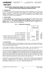
3. BOARD TERMINAL DESCRIPTIONS
Refer to Figure 1 (Panel Board Overview) to see the terminal layout. This section describes the
function of each terminal and is intended for reference or to allow the installer to use the panel in
a novel way.
FIG. 1: PANEL BOARD OVERVIEW
+V IN, ZONE 2
+2
+V IN, ZONE 3
+3
+V IN, ZONE 4
+4
DC NEG FROM POWER SUPPLY
R
+V TO SONALERT (PREWIRED)
A
Y1
+V IN DRIVES YEL. LED #2 (AM OPTION)
Y2
+V IN DRIVES YEL. LED #3 (AM OPTION)
Y3
+V IN DRIVES YEL. LED #4 (AM OPTION)
Y4
+V TO PULSING SONALERT (PREWIRED)
AY
+V OUT WHEN RESPECTIVE SWITCH ONCONNECT FAIL SAFE LOCK
S2 +V IN ILLUMINATES GREEN INDICATOR
L2
+V OUT WHEN RESPECTIVE SWITCH ONCONNECT FAIL SAFE LOCK
S3 +V IN ILLUMINATES GREEN INDICATOR
+V OUT WHEN RESPECTIVE SWITCH ONL3 CONNECT FAIL SAFE LOCK
+V OUT WHEN SWITCH OFF/FAIL SECURE LOCK
E3 +V IN SHUNTS VIOLATION (LEGAL RELEASE)
ZONE 4
+V IN DRIVES YEL. LED #1 (AM OPTION)
L1
+V OUT WHEN SWITCH OFF/FAIL SECURE LOCK
E2 +V IN SHUNTS VIOLATION (LEGAL RELEASE)
ZONE 3
+V FROM RESET (PREWIRED)
S1 +V IN ILLUMINATES GREEN INDICATOR
+V OUT WHEN SWITCH OFF/FAIL SECURE LOCK
E1 +V IN SHUNTS VIOLATION (LEGAL RELEASE)
ZONE 2
+1
ZONE 1
+V IN, ZONE 1
S4 +V IN ILLUMINATES GREEN INDICATOR
+V OUT WHEN RESPECTIVE SWITCH ONL4 CONNECT FAIL SAFE LOCK
+V OUT WHEN SWITCH OFF/FAIL SECURE LOCK
E4 +V IN SHUNTS VIOLATION (LEGAL RELEASE)
TERMINALS "+1, +2, +3, +4”: They constitute the +V inputs for zones 1, 2, 3, and 4. In most installations,
these four terminals wire directly to the +V output of the power supply and are therefore jumped together. The fact
that they are separate on the board, however, allows the use of upstream switches to individual zones.
TERMINAL "-”: This is the DC negative input for the board.
TERMINAL "R": This is the violation reset input. It is prewired through a momentary N.O. toggle reset switch.
When the Sonalert sounds, accompanied by a red indicator, the violation condition (lock not secure when it should
be) has occurred. Once the violation condition has been corrected, the Sonalert will continue to sound as this is a
latching condition. Pressing the reset toggle supplies +V into this terminal and the condition will reset. All R
terminals on all the board used in the panel are wired together. A single reset toggle serves to reset a violation on
any board in the entire panel.
TERMINAL "A": This prewired output supplies +V to drive the Sonalert when a violation condition has
occurred (after a 2 second delay). All A terminals from all panel boards are wired together so that any of them can
operate the single Sonalert.
Rev. A.1, 10/99
Page- 7
TERMINALS "Y1, Y2, Y3, Y4": These input terminals are only active if the AM option has been supplied.
With the option, a second (yellow) LED will be mounted adjacent to the standard bicolor. When the respective "Y"
terminal receives +V, the yellow LED will illuminate. This is used to annunciate any condition monitored from a dry
contact closure or voltage signal. Most commonly, the yellow LED annunciates the beginning of delayed exit for a
door but other purposes are possible.
TERMINAL "AY": This is a +V voltage output that is on when any Y terminal is on (illuminating the yellow
LED). It is active only when the AM option is supplied. It is prewired to drive a pulsing Sonalert so that when
any yellow LED illuminates, it will be annunciated with a distinctive sound. With multiple boards in a panel, all AY
terminals wire together with a single wire from any one going to the pulse Sonalert input. If the user wishes to
disable the AY audible alert, this single wire may be cut.
TERMINALS "S1, S2, S3, S4": These input terminals illuminate the green side of the respective zone
bicolor LED when they receive +V. They are connected to lock or door status output such that closed or +V =
secure for the zone. In the normal condition of the panel, the zones are secure, the bicolor LED's show green and
the S terminals receive +V.
TERMINALS "L1, L2, L3, L4": These terminals supply +V when the respective toggle switch is in the on
position (points toward the LED). They are connected to fail safe locks. If fail secure locks are employed, these
terminals are used only when status or remote release switches are present on the zone. The L terminals are used
to power the switch commons.
TERMINALS "E1, E2, E3, E4": These terminals are both an input and an output. When the respective
toggle switch is off (points away from the LED), the terminals supply +V to release a fail secure lock. At the same
time, the yellow indicator in the toggle switch bat illuminates (this annunciates "legal release" of the lock). Also the
violation condition of the zone is shunted. While the lock is legally released (toggle off; bicolor off; toggle bat yellow
LED on), the zone will not violate. As the lock status input (S terminals) reports insecure (since the lock has been
released), the green bicolor indicator will go off but the red side will not come on as would be the case if the
respective E terminal did not have +V on it.
As stated above, turning the toggle off puts +V on the E terminal. The same can be accomplished from a remote
switch. If, for instance, a remote release switch sends power to a fail secure lock, it will "legally" release. This will
input power to the E terminal as it is already connected to the lock. The yellow indicator in the toggle bat will light
up even though the toggle remains in the on position and the violation condition will be shunted.
Annunciating legal release and shunting zone violation is also accomplished with a fail safe lock. The fail safe lock
connects to the L terminal. A remote SPDT switch can legally release it. The common and NC contacts break
power to the fail safe lock, but the NO contact is wired back to the E terminal. When the fail safe lock is therefore
remotely released by this switch, the respective E terminal receives +V and the toggle bat indicator lights up
annunciating the condition and shunting the violation.
4. WIRING
4.1 POWER INPUT WIRING
The board requires a source of DC voltage which it distributes to the locks. +V from the power
supply is input to terminals +1, +2, +3 and +4. If the power supply you are using has a single
DC output, the +1 through +4 terminals should be jumped together. They are individually used if
the power supply has multiple breakered outputs or if you are employing upstream switches to
deactivate any of the panel zones. Negative voltage from the power supply is always input to
terminal “-”. Note that four wires are typically required to be run to each door unless
Securitron’s XDT board is being used in a delayed exit installation. Then six wires are required.
Figure 2, below, shows the hookup where you jump together the positive terminals (on the left)
and use of the positive terminals individually with a Securitron power supply that employs a CCS
Rev. A.1, 10/99
Page- 8
board. The CCS board provides multiple, current limited two Amp outputs on terminals marked
P1, P2 etc. The advantage of using these individual outputs as shown on the right of Figure 2 is
that any short circuit in the downstream wiring will take out only one of the breakers on the CCS
board and the rest of the installation will continue to operate. Use of a multiple output Securitron
power suppy materially increases the reliability of the installation and is therefore recommended.
Note however that you can always add in-line fuses or breakers to any single output power
supply to create the effect of the Securitron supply with CCS board.
FIG. 2: POWER SUPPLY TO LCP BOARD WIRING
IF POWER SUPPLY HAS SINGLE
DC OUTPUTS, THE "+" TERMINALS
MUST BE JUMPED TOGETHER AS
SHOWN.
R1
P1
P2
P3
P4
+4
+3
+2
+1
P5
RED FLYING LEAD FROM
RESET TOGGLE
+4
+3
+2
RED FLYING LEAD FROM
RESET TOGGLE
POWER
SUPPLY
SECURITRON POWER SUPPLY
WITH CCS BOARD PERMITS
INDIVIDUAL OPERATION OF "+"
TERMINALS
+1
NOTE: IF PB OPTION IS SUPPLIED, DC NEG
CONNECTS TO FLYING BLACK LEAD RATHER
THAN TO CIRCUIT BOARD "-" TERMINALS
EACH "P" TERMINAL MAY OPERATE ONE OR
MORE "+" TERMINALS DEPENDING ON THE
NUMBER OF ZONES IN THE PANEL.
On both examples shown in Figure 2, note that there is a red flying lead from the underside of
the reset toggle. This wire simply supplies +V to the toggle common and then, when the spring
loaded toggle is pressed, +V is input to the “R” terminal of the board which is used to reset the
violation alarm function. The red flying lead requires constant +V so that the panel violation
alarm can always be reset. The reason why the factory doesn’t connect this wire is that when
individual breakered outputs or ‘upstream” switches are used to operate the “+” terminals on the
board (shown on the right of Figure 2), constant +V cannot be guaranteed to any “+” terminal.
Therefore, as Figure 2 shows, when you have only a single source of +V, connect the red flying
lead to any of the “+” terminals (they will all get constant power). When you can employ
individually breakered +V outputs (right side of Figure 2), connect one of the breakers
separately to the red flying lead in order to guarantee that it will always have power on it.
Supposing that you have to choose between putting two panel zones on one breakered “P”
output terminal or sharing a breakered “P” terminal between a panel zone and the red flying
lead, it is better to do the former. The panel user will expect to always be able to reset a
violation alarm even if one of the panel zones is de-powered from a short circuit or other
condition.
Note that often the number of panel zones exceeds the number of “P” terminals in the power
supply. Each “P” terminal can power multiple “+” input terminals so long as the current rating of
the “P” terminal is not exceeded. This in turn depends on the voltage and the type of lock being
Rev. A.1, 10/99
Page- 9
controlled by the panel zone. Not also that Securitron can supply additional breakered output
boards for the power supply (part #CCB-8).
If the “PB” option is supplied, (see Sections 2.2 and 5.2) power supply DC neg does not
connect to the “-” terminals on the boards but rather to a flying black lead coming from the push
button switch. Note that the board “-” terminals will all be pre-wired to the button when this
option is present. Pressing the button breaks DC negative which releases all fail safe locks.
The button does not break +V so as to preserve the capability of multiple breakered inputs.
Finally, note that for a standard board, the 12 position terminal strip that includes the four “+”
terminals and "-" requires field wiring to only these terminals. The other terminals on the
strip are either prewired (R and A) or used only if options are supplied (see section 5 for option
wiring). All the rest of the field wiring is on the second 12 position terminal strip that includes the
S, L, and E terminals for zones 1 through 4. If the panel has been delivered in a wall mount
NEMA 1 cabinet, the installer does not wire directly to the boards but rather to a channel mount
terminal strip in the base of the enclosure. The terminal identification, however, is the same.
4.2 FAIL SAFE LOCKS
Figure 3 shows 5 different ways of wiring fail safe locks to the panel board. The exact wiring
done will depend upon the equipment utilized and the requirements of the job. All panel to lock
wiring concerns only 3 panel terminals: S, L and E for the respective zone (4 zones per board).
Check the description of each wiring method to see which (if any) applies to your installation.
Later in the manual, other typical wiring schemes will be shown.
TYPE 1 FAIL SAFE
The type 1 drawing is the simplest. It utilizes a fail safe lock controlled directly by the panel with
no other release devices employed. No lock or door status monitoring switch is used.
As the drawing shows, lock power comes from the L terminal and the S terminal is connected to
the power wire at the lock. With this connection, when the lock is powered, the S terminal will
receive +V which will illuminate the green side of the bicolor LED. When the lock is released
from the panel toggle, the bicolor will be off and the toggle bat yellow LED will come on. Since
the door is not monitored, the red violation LED should never come on and sound the Sonalert.
An exception would be if the power wire to the lock was cut so that +V could not reach the S
terminal when the lock is powered.
TYPE 2 FAIL SAFE
This connection employs a lock or door status switch which is closed when the lock or door is
secure. Lock status provides superior security as the door can be closed but the lock may not
be fully secure. The status switch connects to the S terminal and therefore illuminates the green
side of the bicolor when the door is secure. When the lock is released from the toggle, power is
removed from the status switch so the green indicator goes out and the yellow toggle bat
indicator comes on. If, however, the status switch opens (because the lock becomes insecure
or the door is open) at a time when the lock is powered, this is the violation condition and after a
2 second delay, the bicolor will turn red and the Sonalert will sound. After the door has been
resecured, the bicolor will show orange as both the red and green sides will be on. The panel is
then reset by momentarily pressing the reset toggle. This will extinguish the Sonalert and
restore green condition on the indicator.
On some installations, both a lock and door status switch may be employed. They should be
connected in series so that the lock must be reporting secure and the door must be closed
before the green indicator will come on. In theory the lock status switch cannot report secure if
the door is open. However, combining the 2 switches enhances security in case the lock status
switch fails or is tampered with.
Rev. A.1, 10/99
Page- 10
FIG. 3: FAIL SAFE LOCK CONNECTIONS
TO DC NEG
TYPE 1
S
FAIL SAFE +
L
LOCK
SIMPLE LOCK HOOKUP WITH NO STATUS MONITORING.
S AND L TERMINALS JUMPERED TOGETHER TO AVOID
VIOLATION ALARM.
TO DC NEG
E
S
FAIL SAFE +
L
S
TYPE 3
L
LOCK OR DOOR STATUS SWITCH
CLOSED WHEN SECURE
FAIL SAFE -
COM NC
E
+
LOCK OR DOOR STATUS SWITCH
CLOSED WHEN SECURE
NO
REMOTE RELEASE
SWITCH
S
L
E
LOCK
TYPE 4
COM NC
COM NC
NO
NO
+
L
MAGNALOCK
RED
E
TYPE 5
TO DC NEG
WHITE "S" SENSTAT BLACK
FAIL SAFE LOCK
2 RELEASE SWITCHES
IN SERIES ARE SHOWN.
EITHER RELEASES LOCK.
LOCK OR DOOR STATUS SWITCH
CLOSED WHEN SECURE
2 REMOTE RELEASE
SWITCHES IN SERIES
S
A REMOTE RELEASE SWITCH IS ADDED
SUCH AS CARD READER, KEYPAD,
PUSH BUTTON, KEYSWITCH ETC.
TO DC NEG
TYPE 2
TO DC NEG
E
LOCK
A LOCK OR DOOR STATUS SWITCH IS ADDED
TO PROVIDE MONITORING AND VIOLATION
ALARM FUNCTION
WHEN "S" SENSTAT MAGNALOCK IS USED, THE WHITE
WIRE PROVIDES A LOCK STATUS VOLTAGE OUTPUT
WHICH PERFORMS THE SAME FUNCTION
AS THE DRY STATUS SWITCHES SHOWN ABOVE.
Rev. A.1, 10/99
Page- 11
TYPE 3 FAIL SAFE
This is the most common configuration. The status switch is still present but a remote release
switch such as a card reader, digital keypad, keyswitch, switch equipped panic bar, or
Securitron's Touch Sense Bar is present at the door. The lock can be released from the panel
toggle or from this remote switch. When the remote switch is used, the panel will annunciate
"legal release" just as if the toggle was used (bicolor off and toggle bat yellow LED on). The NC
contacts of the remote switch release the lock but the NO contact inputs +V to the E terminal.
When +V is on the E terminal, the toggle bat yellow LED comes on and the violation condition is
shunted. The bicolor turns off as the status switch won't supply +V to the S terminal when the
lock is released. When the remote switch repowers the lock, +V is removed from the E terminal
(yellow toggle bat LED turns off). The green indicator must come on within 2 seconds (lock
secures or door closes) or the violation condition will occur and the bicolor will turn red.
Note that an SPDT remote switch is necessary for this connection and the contacts must be dry.
Many remote switches such as card readers, digital keypads or Securitron's Touch Sense Bar
require power. They should receive constant power with their contacts left dry to connect as
shown in the Type 3 drawing. Power is most easily furnished from the associated “+” terminal
for the zone. See section 4.4 for an example of powering a switching device at the door.
TYPE 4 FAIL SAFE
This is the same as Type 3 except that 2 remote switches are in series. An example would be
a card reader for entry and a push button for exit. The SPDT contacts of each remote switch
are connected in NC series as shown so that either switch can release the lock. The NO
contacts are tied together so that when either switch releases the lock, the respective NO
contact inputs +V to the E terminal which annunciates legal release. Any number of remote
switches may be connected in this manner. Note that many remote switches such as card
readers, digital keypads or Securitron's Touch Sense Bar require power. They should receive
constant power with their contacts left dry to connect as shown in the Type 4 drawing.
Power is most easily furnished from the associated “+” terminal for the zone. See section 4.4
for an example of powering a switching device at the door.
TYPE 5 FAIL SAFE (MAGNALOCK)
This drawing shows the specialized use of Securitron's "S" Senstat Magnalock. This version of
the Magnalock incorporates a lock status sensing voltage output which replaces the status
switch as shown in Types 2, 3 and 4. When the Magnalock is secure, the white wire outputs +V
which then directly inputs to the S terminal to illuminate the green side of the bicolor. Naturally,
the Magnalock can be combined with remote release switches as shown in the Type 3 and 4
drawings.
4.3 FAIL SECURE LOCKS
Figure 4 shows 4 different ways of wiring fail secure locks to the panel board. The exact wiring
done will depend upon the equipment utilized and the requirements of the job. All panel to lock
wiring concerns only 3 panel terminals: S, L and E for the respective zone (4 zones per board).
Check the description of each wiring method to see which (if any) applies to your installation.
Later in the manual, other typical wiring schemes will be shown.
Rev. A.1, 10/99
Page- 12
FIG. 4: FAIL SECURE LOCK CONNECTIONS
L
FAIL SECURE +
E
L
E
LOCK
SIMPLE LOCK HOOKUP WITH NO STATUS MONITORING.
S AND L TERMINALS JUMPERED TOGETHER TO AVOID
VIOLATION ALARM.
LOCK OR DOOR STATUS SWITCH
CLOSED WHEN SECURE
A LOCK OR DOOR STATUS SWITCH IS ADDED
TO PROVIDE MONITORING AND VIOLATION
+ FAIL SECURE ALARM FUNCTION
LOCK
TYPE 2
TO DC NEG
S
TO DC NEG
TYPE 1
S
LOCK OR DOOR STATUS SWITCH
CLOSED WHEN SECURE
TYPE 3
COM NC
L
NO
+
E
FAIL SECURE LOCK
REMOTE RELEASE SWITCH
TO DC NEG
S
A REMOTE RELEASE SWITCH IS ADDED
SUCH AS CARD READER, KEYPAD,
PUSH BUTTON, KEYSWITCH ETC.
S
L
COM NC
COM NC
NO
NO
E
TYPE 4
2 REMOTE RELEASE
SWITCHES
FAIL SECURE +
LOCK
TO DC NEG
LOCK OR DOOR STATUS SWITCH
CLOSED WHEN SECURE
2 RELEASE SWITCHES
ARE SHOWN.
EITHER RELEASES LOCK.
Rev. A.1, 10/99
Page- 13
TYPE 1 FAIL SECURE
The type 1 drawing is the simplest. It utilizes a fail secure lock controlled directly by the panel
with no other release devices employed. No lock or door status monitoring switch is used.
As the drawing shows, lock power comes from the E terminal and the S terminal and L terminal
are jumpered together. With this connection, when the lock is unpowered (secure), the S
terminal will receive +V from the L terminal which will illuminate the green side of the bicolor
LED. When the lock is powered (released) from the panel toggle, the bicolor will be off and the
toggle bat yellow LED will come on. Since the door is not monitored, the red violation LED
should never come on and sound the Sonalert.
TYPE 2 FAIL SECURE
This connection employs a lock or door status switch which is closed when the lock or door is
secure. Lock status provides superior security as the door can be closed but the lock may not
be fully secure. The status switch connects between the L and the S terminal and therefore
illuminates the green side of the bicolor when the door is secure. When the lock is released
(powered) from the toggle, power is removed from the status switch so the green indication
goes out and the yellow toggle bat indicator comes on. If, however, the status switch opens
(because the lock becomes insecure or the door is open) at a time when the lock is unpowered,
this is the violation condition and after a 2 second delay, the bicolor will turn red and the
Sonalert will sound. After the door has been resecured, the bicolor will show orange as both the
red and green sides will be on. The panel is then reset by momentarily pressing the reset
toggle. This will extinguish the Sonalert and restore green condition on the indicator.
In some cases, both a lock and door status switch may be used. They should be connected in
series so that the lock reports secure and the door is closed before the green indicator comes
on. In theory lock status can't report secure if the door is open. However, combining the 2
switches enhances security in case the lock status switch fails or is tampered with.
TYPE 3 FAIL SECURE
This is the most common configuration. The status switch is still present but a remote release
switch such as a card reader, digital keypad, or keyswitch is present at the door. The lock can
be released from the panel toggle or from this remote switch. When the remote switch is used,
the panel will annunciate "legal release" just as if the toggle was used (bicolor off and toggle bat
yellow LED on). The NO contacts of the remote switch release the lock by powering it. Note
that the NC contacts of the release switch feed the common of the lock/door status switch. This
is to make sure the green indicator goes out (+V removed from S terminal) when the lock is
legally released from the remote switch. If a door status switch was used, it would remain
closed (green light on) until the door was actually opened. We prefer to show "legal release"
(bicolor off) as soon as the remote switch is used. This is clearer for the panel operator. When
the remote switch resecures the lock, +V is removed from the E terminal (yellow toggle bat LED
turns off). The green indicator must come on within 2 seconds (lock secures or door closes) or
the violation condition will occur and the bicolor will turn red.
Note that an SPDT remote switch is necessary for this connection and the contacts must be dry.
Many remote switches such as card readers, or digital keypads require power. They should
receive constant power with their contacts left dry to connect as shown in the Type 3
drawing. Many remote switches such as card readers, digital keypads or Securitron's Touch
Sense Bar require power. They should receive constant power with their contacts left dry to
connect as shown in the Type 3 drawing. Power is most easily furnished from the associated
“+” terminal for the zone. See section 4.4 for an example of powering a switching device at the
door.
Rev. A.1, 10/99
Page- 14
TYPE 4 FAIL SECURE
This is the same as Type 3 except that 2 remote switches are used. An example would be an
entry card reader and an exit push button. The SPDT contacts of each remote switch are
connected in NC series as shown so that the use of either switch cuts power to the status switch
common extinguishing the green indicator. The NO contacts are connected in parallel so that
either switch releases the lock. Any number of remote switches may be connected in this way.
Note that many remote switches such as card readers, digital keypads or Securitron's Touch
Sense Bar require power. They should receive constant power with their contacts left dry to
connect as shown in the Type 4 drawing. Power is most easily furnished from the associated
“+” terminal for the zone. See section 4.4 for an example of powering a switching device at the
door.
4.4 POWERED SWITCHING DEVICES AT THE DOORS
The wiring methods shown in Figures 3 and 4 do not specifically show operation with a powered
switching device at the door such as a card reader or digital keypad. This is to keep the
drawings simple and also recognizes the fact that powered devices such as card readers will
often get their power separately and only their output relay will be part of the LCP wiring
scheme. When, however, the powered switching device receives its power from the same
supply that operates the LCP, the most convenient way to supply power to the device is from
the power terminals on the LCP board (as is pointed out in the previous sections). Figure 5
shows an example of a powered switching device mounted at the door. It includes Securitron’s
model DK-26 digital entry keypad and an “S” Senstat Magnalock which is a fail safe electric
lock. Note that for clarity, we have not shown a switching exit device such as Securitron’s
Touch Sense Bar being used to release the lock from the inside but you must always be
concerned to adhere to all building codes as regards egress safety.
FIG. 5: POWERED SWITCHING DEVICE AT DOOR WIRING (DK-26 + MAGNALOCK)
S
LCP
BOARD
L
E
F
DC IN /OUT
+
DK-26 CPU
WHITE
RED
NC1 C1
NOTE: "+" TERMINAL
ON LCP BOARD WILL
BE +1, +2, +3 OR +4
DEPENDING ON ZONE
NO1
"S" SENSTAT
MAGNALOCK
BLACK
Rev. A.1, 10/99
Page- 15
There are a number of things to consider about this drawing. The main point is to show that a
powered switching device at the door should preferably draw constant power from the LCP
board power terminals (assuming the device isn’t receiving separate power). It would be
possible as an alternate method to provide power to the DK-26 from the LCP board “L” terminal
(which now only goes to terminal C1 of the DK-26). When the toggle is used to release the lock,
power will be off the “L” terminal. The fail safe Magnalock will release but the DK-26 will lose
power. This will work and does eliminate a wire in the run from the panel to the door but it
reduces the reliability of powered switching devices to have power turned off and on many times
each day so the alternate method is not prefered.
4.5 WIRING UNUSED ZONES
If the panel has zones that are not presently wired to locks, steps must be taken to avoid going
into violation as there will be no zone secure signal from an unwired zone. Simply connect the
E terminal from all unwired zones to the respective board “+” terminal. The E terminal will
receive constant +V which will keep it in a state of "legal release" (bicolor off; toggle bat indicator
on).
4.6 WIRING WITH RELEASE HOLD TIMER (FAIL SAFE AND FAIL SECURE)
Another common requirement is that the remote release switch at the door will activate a
release hold timer which, in turn, releases the lock. Examples would be a momentary keyswitch
or push button which activates the timer. The person using the door turns the key or pushes the
button. The timer then opens the door for approximately 5 seconds which is enough time for the
individual to conveniently move through the door. Numerous manufacturers make this type of
timer which may be termed a "release hold" timer as it releases the lock and holds the release
for an amount of time. Such timers are also called "off delay" timers. In selecting the timer, the
requirements are that it has an SPDT relay output and that it operates on the panel DC voltage.
A functional hookup can be derived from Figure 3 or 4 once it's realized that the timer relay
contacts take the place of the remote release switch contacts. Figure 6, however, shows
connections that are particularly effective for timer installations and which may not be obvious.
The first drawing in Figure 6 shows the hookup for a fail safe lock with timer activated by a
momentary remote release switch. Securitron's TimeMate timer is used as an example but
timers from other manufacturers will usually have the same terminals and connection scheme.
Referring to the drawing, note that the timer is powered (red=+ in) from the L terminal. When
the remote switch is activated, +V is input to the yellow (trigger) wire of the timer. This
energizes the timer relay which breaks power to the lock (white=com; green=NC). The timer
blue wire (NO) inputs +V to the E terminal which annunciates legal release until the timer times
out and reenergizes the lock. Note finally that when the remote switch activates the timer, it
also removes power from the timer common. We call this a double break connection. Were
the timer to experience a fault, the door could still be used by activating the remote switch with
one hand and pushing open the door with the other. This allows use of the door until the timer
can be replaced. As always, if the lock is an "S" Senstat Magnalock, the white wire connects
directly to the panel S terminal replacing the lock/door status switch
The second drawing in Figure 6 shows the hookup for a fail secure lock with timer activated
by a momentary remote release switch. Securitron's TimeMate timer is used as an example but
timers from other manufacturers will usually have the same terminals and connection scheme.
Rev. A.1, 10/99
Page- 16
FIG. 6: FAIL SAFE/FAIL SECURE TIMER CONNECTIONS
LOCK OR DOOR STATUS SWITCH
CLOSED WHEN SECURE
FAIL SAFE
S
L
RED (+)
FAIL SAFE
WHITE (COM)
TIMEMATE
GREEN (NC)
CO M NC
+
LOCK
YELLOW
E
(TRIGGER)
BLUE (NO)
TO DC NEG
REMOTE RELEASE SWITCH
NO
BLACK (-)
LOCK OR DOOR STATUS SWITCH
CLOSED WHEN SECURE
WHITE
S
CO M
L
GREEN
RED
TIMEMATE
BLACK
YELLOW
(TRIGGER)
NO
E
REMOTE RELEASE SWITCH
FAIL SECURE
BLUE
+
LOCK
TO DC NEG
FAIL SECURE
Referring to the fail secure drawing, note the timer is powered (red= + in) from the L terminal
and that the timer relay com (white) also receives +V from this source. The remote release
switch momentarily inputs +V to the timer trigger (yellow) which energizes the timer relay and
powers (releases) the fail secure lock via the timer's NO contact (blue). This also inputs +V to
the E terminal thereby annunciating legal release at the panel. The timer's NC contact (green)
breaks +V to one side of the lock/door status switch insuring that the green panel indicator will
go out when the lock is released from the timer.
4.7 REMOTE INDICATOR WIRING
Remote switches used at the door often have single or double (bicolor) indicators. The
indicators ought to be wired in such a way as to aid proper use of the door by individuals
authorized to employ the remote switches. To operate, naturally the indicators have to employ
the panel DC voltage. Usually, they are LED indicators. If they are incandescent, be sure that
the cumulative effect of the indicators does not overload the power supply.
If a single indicator is available at the door, we advise that it be wired to the zone S terminal.
When the door is secure, the indicator will be on. Persons passing the door will be assured that
Rev. A.1, 10/99
Page- 17
"the system is working". When the release switch is used, the indicator will go out which will
prompt the individual to go through the door.
If two indicators are present, one should be wired to the zone S terminal and the other to the
zone E terminal. This creates a lamp switching effect which provides more positive prompting
for door use. As an example, suppose a green and red indicator are present on a push button
plate. With the green indicator wired to the S terminal, green will annunciate the normal
(secure) condition of the door. This is the same as the panel green indication. With the red
indicator wired to the E terminal, it will come on whenever the lock is legally released from either
the remote switch or the panel toggle. This provides a strong prompt for use of the door. If a
release hold timer is in the installation (section 4.5), the red indicator will come on for the
amount of time set on the timer. Any time that both indicators are out will show that the door is
in violation (the panel Sonalert will be on). If indicators are present on more than one switch (an
example would be an entry keyswitch and exit button) they should be wired in parallel so that
the annunciation is the same from both sides of the door.
4.8 AC LOCK CONTROL
Many electric locks are intended for operation on 12 or 24 volts AC. The panel, however, only
operates on DC and cannot supply AC from its toggle switch control outputs. Most electric locks
which operate on AC will also operate on DC, so the installer should check this point. If,
however, the locks must operate on AC or on a voltage other than 12 or 24, this can only be
done by using the panel to energize and deenergize relays which operate on the panel voltage.
The relay contacts will then switch the "foreign" lock voltage from a second power supply. This
technique is the same that must be employed if the locks draw more than 1.5 Amps current.
5. OPTION WIRING
5.1 SILENCE LATCH WIRING (OPTION "SL")
FIG. 7: FIELD INSTALLATION OF SILENCE LATCH
FIG. 5: FIELD INSTALLATION OF SILENCE LATCH
PUSH BUTTON
PANEL TERMINAL
L+
NO
A
+
-
COM
NC
NO
+
COM
-
L-
COM. NEG.
RELAY
BREAK EXISTING CONNECTION BETWEEN A
AND SONALERT +. INSTALL BUTTON AND RELAY
AS SHOWN. SONALERT NEGATIVE ALREADY WIRED.
SONALERT
L+=INDICATOR +
L-=INDICATOR -
Rev. A.1, 10/99
Page- 18
The silence latch is entirely prewired. However, if the panel that has been supplied was
ordered without a silence latch, one can be added comparatively easily in the field. The
components required are an SPDT relay of the panel voltage and an illuminated normally open
momentary switch with an indicator that also operates on the panel voltage.
Figure 7 shows the circuit. The prewired connection between the Sonalert + input and one of
the A terminals is broken with the components wired in as shown in the drawing. In a violation
event, +V appears on terminal A. This operates the Sonalert through the COM and NC relay
terminals. When the push button is pressed, it energizes the relay which latches in through its
NO contact. This shuts off the Sonalert and illuminates the push button indicator. When the
violation is cleared, +V is removed from terminal A and the silence latch resets, ready for the
next violation event.
5.2 EMERGENCY RELEASE WIRING (OPTION "PB")
The PB option is factory supplied for use only with fail safe locks. Normally fail secure locks are
not used in a safety type situation where emergency release is desired. The only wiring change
from a standard panel is that the negative terminals of all the boards “-” are already wired to the
push button. A single black flying lead emerges from the push button and DC negative
external power of sufficient capacity to operate the entire system should be connected to
this black wire. When the button is pressed, all DC power will be broken which will
immediately release all the locks. Make sure you terminate the lock negative wires at the
panel “-” terminals rather than directly back to the power supply or the push button break will
not work. At the same time, the button will illuminate red. Pressing the button a second time
will restore power.
The reason that the PB option is set up to break the negative circuit instead of the positive is to
preserve the ability to run separate +V inputs to each board zone. This can allow separately
breakered inputs from a Securitron power supply or the installation of upstream switches.
If the present panel has been supplied without this options, it may be added in the field. Follow
the connections shown in Figure 8. Be sure to select a button with heavy enough contacts
to break all the DC power.
FIG. 8: FIELD INSTALLATION OF EMERGENCY RELEASE BUTTON
CONSTANT +V
L+=INDICATOR +
L-=INDICATOR DC NEG FROM
POWER SUPPLY
NO
COM
L-
L+
BUTTON NC CONNECTS
TO "-" TERMINALS
ON ALL BOARDS
IN PANEL
NC
ALTERNATE ACTION
ILLUMINATED PUSH BUTTON
MAKE SURE EQUIPMENT
AT DOORS TERMINATES
ITS NEGATIVES AT PANEL
"-" TERMINALS
5.3 WIRING OF "AM" OPTION AND SECURITRON'S XDT BOARD FOR DELAYED EXIT
One of the most common uses of the AM option (extra monitoring lights with pulsing Sonalert) is
for an exit delay installation (allowable only for fail safe locks). Such an installation complies
with the NFPA Life Safety code as regards delayed exit (special locking arrangements) and
typically incorporates multiple functions:
Rev. A.1, 10/99
Page- 19
The locks may be immediately released by the associated panel toggle. Optionally, a remote
release switch may be provided at the door such as a card reader, keyswitch etc. An exit device
is provided for delayed egress. Pressing the exit device starts a 15 or 30 second irrevocable
delay after which the lock releases. The lock remains released until reset by a switch (usually a
keyswitch at the door).
Methods of interwiring the LCP board with the XDT timers at the door can become very
complicated. The reason is that both products have been designed to perform numerous
functions. Combining them therefore, can be done in a nearly endless number of ways. In so
doing, it's easy to miss some point that can lead to improper operation, false alarms etc. One
particular note is that if you employ the KP1 or MK1 switch bypass option, you will not
completely bypass the toggles. The toggle itself will not open the door but (when depressed)
will put the door into free egress mode rather than delayed exit mode. We advise not using
this option with delayed exit.
To simplify this process, we advocate two different connection schemes which depend on
whether the bypass function of the XDT board is to be used or not. The bypass function
allows the use of a momentary switch closure to release the lock immediately for authorized
entry or exit with the released state being held for five seconds. The bypass function not only
provides the five second release time (and therefore replaces an outboard timer) but
suppresses the XDT board's alarm outputs and delayed exit function during the 5 second
period. Since the lock is being "legally" released, it's inappropriate to initiate a delayed exit
sequence or send out alarm signals.
FIG. 9: GENERAL LCP/XDT CONNECTIONS WITHOUT USE OF BYPASS
LOCAL RELEASE SWITCH
LCP "L" TERMINAL
COM
NC
NO
LCP "E" TERMINAL
RS
IN
INITIATE (NC)
RESET (NC)
FROM POWER SUPPLY
IF A LOCAL RELEASE SWITCH IS NOT
USED, LCP "L" CONNECTS DIRECTLY
TO "C3" AND TO TOP OF INITIATE SWITCH;
LCP "E" CONNECTS TO "FE".
FE
NO
BP
NC
LS
C2
0V (NEG)
+V
MOV
NC
C3
NO
+
FAIL SAFE
LOCK
DOOR/LOCK STATUS
SWITCH. CLOSED
WHEN SECURE.
NC
C1
XDT BOARD
NO
LOCAL
ALARM
LCP "S" TERMINAL
LCP "Y" TERMINAL
Rev. A.1, 10/99
Page- 20
Most installations do not require use of the bypass function. Even if there is a local authorized
entry or exit device at the door, it will often have its own timed relay output. We believe that the
LCP/XDT combination works more clearly when the bypass function is not used and therefore
recommend employing the first connection scheme shown in Figure 9 where possible.
Figure 9 shows the general case of an LCP/delayed exit installation. Delayed exit takes place at
the door as controlled by the initiate and reset switches. The LCP panel serves two functions. It
releases the lock for authorized entry or exit and also monitors the door as follows:
In the normal (secure) condition, the main LED is green and no alarm sounds.
During the nuisance delay and release delay period, the main LED remains green but the
"AM" LED illuminates yellow and a pulsing Sonalert sounds.
When the lock releases at the end of the delay, the yellow AM LED goes out. The main
LED turns red and the steady Sonalert sounds.
When the lock has been reset (relocked), the main LED turns orange and the panel reset
toggle may be used to halt the Sonalert and restore the main LED to green.
When the lock is released for authorized use from the panel toggle or from a local release
switch, the main LED turns off and the toggle bat illuminates yellow. No alarm sounds.
Note on the drawing that the local release switch may or may not be present. If no local release
switch is used, LCP terminal "L" connects directly to XDT terminal "C3" and and to the “top” of
the initiate switch (the switch contact that does not connect to “IN”). LCP terminal "E" connects
directly to XDT terminal "FE". If there is more than one local release switch, for authorized exit
and entry for instance, the NC contacts of the two release switches would connect in series.
The NO contacts would each connect to XDT terminal "FE".
There are a number of reasons for the particular wiring method in Figure 9. Note first the
connection to terminal “FE” on the XDT board. Inputting +V to this terminal places the XDT
board in “free egress” mode which means that the lock will release (relay #3 deenergizes),
immediately whenever +V is removed from “IN”. No delayed exit event will begin and the XDT
board’s alarm outputs are suppressed. This is the desired effect when either the panel toggle or
a local release switch has “legally” released the lock.
Note also that the initiate switch is powered not directly from the power supply but rather
through the local release switch. The rationale here is that “IN” should not be powered if either
the local release switch or the panel toggle has released the lock. This permits use of the XDT
board’s “DC” terminal which can keep the lock secure after the delay has expired subject to use
of the initiate device for immediate egress. When this function is employed, it is necessary that
the local release switch or panel toggle can still unlock the door whether or not the initiate
device is used.
A variation to Figure 9 occurs if you are not employing an LCP panel without the “AM” option.
This presents the problem of how to annunciate the release delay period. To accomplish this,
remove the jumper from terminal “LS” to +V. Then connect “LS” to the output of the door/lock
status switch (no longer connect it to the LCP “S” terminal”). Jump “C1” to “C2” and then
connect NO2 to the “S” terminal. With this set-up, the remote alarm relay contact, NO2, will
maintain the green LED on the panel in the secure condition. During a delayed exit event, relay
#2 will deenergize at the end of the nuisance delay period and this will create an immediate
violation alarm at the panel. The same alarm will occur after a five second delay if the door/lock
status sensor reports insecure at any time it should be secure, it its output is connected to “LS”.
While Figure 9 shows the general approach to wiring the AM version of the LCP into a delayed
exit installation, Figure 10 shows a specific common example where all Securitron products are
Rev. A.1, 10/99
Page- 21
used. An "S" Senstat Magnalock, Touch Sense Bar and MK keyswitch are employed in place of
the generic fail safe lock, initiate device and reset device.
FIG. 10: LCP/XDT CONNECTION USING SECURITRON MAGNALOCK, TOUCH SENSE
BAR, AND MK KEYSWITCH WITHOUT USE OF BYPASS FUNCTION
LOCAL RELEASE SWITCH
COM
LCP "L" TERMINAL
RED
MK KEYSWITCH
RS
IN
NC
C3
RED
BP
BLK
FE
LCP "S" TERMINAL
WHT TSB
LED
RED
FROM POWER SUPPLY
GRN
GRN
WHT
NC
NO
LCP "E" TERMINAL
BLK
IF A LOCAL RELEASE SWITCH IS NOT
USED, LCP "L" CONNECTS DIRECTLY
TO "C3" AND TO TSB WHITE WIRE;
LCP "E" CONNECTS TO "FE".
LS
0V (NEG)
+V
NO
WHITE
RED "S" SENSTAT
MAGNALOCK
NC
C2
NO
+
NC
C1
XDT BOARD
NO
+ SONALERT
LCP "Y" TERMINAL
Figure 11 shows general wiring when the bypass input is used. This is typically because either
the LCP is using momentary switches or the local release switch is momentary. The bypass
input will release the lock without signalling any alarm for 5 seconds. Use of the bypass input
makes substantial changes in the entire wiring scheme. The lock status or door status switch
no longer reports directly to the panel but rather reports to the XDT board lock status input. The
reason for this is to avoid causing the panel to alarm when bypass is used for legal release.
The XDT's lock status monitoring function will continue to report secure to the panel when any
board function has released the lock and for 5 seconds after it has resecured the lock. This
delay permits a door to complete closing and allows the lock time to "pull in" before an alarm
condition is created.
One particular note is that if you employ the KP1 or MK1 switch bypass option, you will not
bypass the toggles. Use of the toggle will still send power out of the E terminal and from there
to the BP terminal on the XDT board which will release the lock. Do not use this option with
delayed exit.
Rev. A.1, 10/99
Page- 22
FIG. 11: GENERAL LCP/XDT CONNECTIONS WITH USE OF BYPASS
LOCAL RELEASE SWITCH
LCP "L" TERMINAL
COM
NC
IF A LOCAL RELEASE SWITCH IS NOT
USED, LCP "L" CONNECTS DIRECTLY
LCP "E" TERMINAL
NO
TO "C3"; LCP "E" TO "BP"
RESET (NC)
INITIATE (NC)
MOV
RS
NC
IN
C3
FE
NO
BP
NC
LS
C2
0V (NEG)
+V
NO
+
XDT BOARD
FAIL SAFE
LOCK
DOOR/LOCK STATUS
SWITCH. CLOSED
WHEN SECURE.
NC
C1
NO
LOCAL
ALARM
LCP "Y" TERMINAL
When the XDT does report a lock status violation, it does so by deenergizing the remote alarm
relay, so it is this relay's NO contact that reports in to the panel's "S" terminal. The remote
alarm relay also deenergizes from the end of the nuisance delay period until the lock is reset
during a delayed exit event so the panel's monitoring functions are altered from the ones
discussed in the previous wiring scheme (without bypass):
In the normal (secure) condition, the main LED is green and no alarm sounds.
During the nuisance delay period, the main LED remains green but the "AM" LED
illuminates yellow and a pulsing Sonalert sounds.
During the release delay period, the main LED turns red; the AM LED remains yellow and
the steady Sonalert sounds.
When the lock releases at the end of the delay, the yellow AM LED goes out. The main
LED remains red and the steady Sonalert continues to sound.
When the lock has been reset (relocked), the main LED turns orange and the panel reset
toggle may be used to halt the Sonalert and restore the main LED to green.
When the lock is released for authorized use from the panel toggle or from a local release
switch, the main LED remains green and the toggle bat illuminates yellow. No alarm
sounds.
Rev. A.1, 10/99
Page- 23
FIG. 12: LCP/XDT CONNECTION USING SECURITRON MAGNALOCK, TOUCH SENSE
BAR, AND MK KEYSWITCH WITH USE OF BYPASS FUNCTION
LOCAL RELEASE SWITCH
LCP "L" TERMINAL
COM
NC
NO
LCP "E" TERMINAL
IF A LOCAL RELEASE SWITCH IS NOT
USED, LCP "L" CONNECTS DIRECTLY
TO "C3"; LCP "E" TO "BP"
GREEN
BLACK LED
RED
WHITE MK KEYSWITCH RED
RED
TOUCH
WHT SENSE
BAR
RS
NC
IN
C3
FE
NO
BP
NC
LS
C2
NO
+V
+
RED "S" SENSTAT BLACK
MAGNALOCK
LCP "S" TERMINAL
NC
C1
0V (NEG)
XDT BOARD
NO
+ SONALERT
LCP "Y" TERMINAL
Figure 12 shows the same wiring scheme with specific Securitron products. Note a final point.
Since the LCP is monitoring the XDT's lock status reporting function, it automatically receives a
5 second alarm delay. The XDT waits for 5 seconds before violating by deenergizing the
remote alarm relay. The standard LCP panel has its own violation alarm delay controlled by the
electrolytic capacitors on the panel boards. There is no reason to have two alarm delays so
remove the capacitors from the boards by clipping them off.
5.4 SWITCH BYPASS WIRING (OPTION "KP1" OR "MK1" FAIL SAFE LOCKS)
The option comes pre-wired for whichever type of keyswitch has been chosen. However,
if the panel has been supplied without this option, it may be added in the field. Refer to Figure
13. When the keyswitch is in the NC position, the indicator is on and the panel functions
normally. When the keyswitch is in the NO position, power is sent through diodes on the board
to all of the L terminals. They will supply power regardless of the toggle switch position, so fail
safe locks will be pinned secure with respect to toggle position until the keyswitch is again
turned. The panel will continue to monitor normally and remote release of the locks is still
possible.
As the drawing shows, proper connection requires soldering to open pads on the boards. The
boards are "chained" together as shown so that all L terminal will be powered when the
Rev. A.1, 10/99
Page- 24
keyswitch is in the NO position. Be sure that the keyswitch contacts are of adequate capacity to
switch all the power of the panel.
FIG. 13: FIELD INSTALLATION OF BYPASS KEYSWITCH (FAIL SAFE LOCKS)
PANEL BOARD
NO
+V POWER
PANEL BOARD
OPEN PAD
OPEN PAD
C
NC
E4 L4
TO DC NEG
INDICATOR
L1 S1
E4 L4
L1 S1
NEXT BOARD ETC
ALTERNATE ACTION
SPDT KEYSWITCH
THIS CONNECTION REQUIRES SOLDERING. IDENTIFY
THE 2 OPEN PADS ON EACH BOARD NEXT TO
THE TERMINALS AS SHOWN. PADS ARE
INTERCONNECTED ON ALL BOARDS TO THE
KEYSWITCH N.O. TERMINAL AS SHOWN.
Note that when a bypass keyswitch is used together with an emergency release pushbutton
(option “PB”), the push button is bypassed at the same time the toggles are. This is done by
using a two pole keyswitch. One pole operates as is shown in Figure 13 above. The second
pole bypasses the PB contacts which break the negative DC input to the panel. This is to
maintain the security of the locks regardless of what is done to the panel controls until the
keyswitch is again returned to the “normal” position.
5.5 SWITCH BYPASS WIRING (OPTIONS "KP2" OR "MK2" FAIL SECURE LOCKS)
The option comes pre-wired for whichever type of keyswitch has been chosen. However,
if the panel has been supplied without this option, it may be added in the field. Refer to Figure
14. The keyswitch removes power from all the terminal boards. This bypasses the ability of the
toggles to release the locks. The panel's monitoring capability will also be disabled but the
purpose of the keyswitch is to shut down the panel when the operator is absent so this is not an
issue. Note that the keyswitch indicator (which operates on the same voltage) indicates that the
panel is operating normally. Be sure that any field installed keyswitch has contacts of sufficient
capacity to break all of the panel power. Also, make sure you terminate the lock negative wires
to the panel “-” terminals rather than directly to the power supply or this will not work.
The reason that this option is set up to break the negative circuit instead of the positive is to
preserve the ability to run separate +V inputs to each board zone. This can allow separately
breakered inputs from a Securitron power supply or the installation of upstream switches.
If the installation includes remote release switches, an important change must be made
from the lock wiring in Figure 4. Assuming that you wish the remote release switch to
continue to function when the panel is bypassed, it will not if the job is wired as is shown in type
3 or type 4 hookups in Figure 4. The reason is that keyswitch bypass will remove DC negative
from the panel and hence from the return of the fail secure locks. The solution is to run an extra
DC negative wire from the power supply to the remote switch common. The wire is upstream of
Rev. A.1, 10/99
Page- 25
the bypass switch. The remote switch’s NO terminal then connects to the DC negative lock
return wire so that the remote switch will release the lock by connecting the negative side even
when the panel is bypassed. If there is a lock status sensing switch, it connects as in type 2,
Figure 4.
FIG. 14: FIELD INSTALLATION OF BYPASS KEYSWITCH (FAIL SECURE LOCKS)
ALTERNATE ACTION
KEYSWITCH
SWITCH NC CONNECTS
TO "-" TERMINALS
ON ALL BOARDS
IN PANEL
DC NEG FROM POWER SUPPLY
MAKE SURE EQUIPMENT
AT DOORS TERMINATES
ITS NEGATIVES AT PANEL
"-" TERMINALS
TO DC NEG
INDICATOR
6. USE OF MULTIPLE PANELS
It is often a requirement that more than one LCP is employed to control and monitor the same
group of doors. This can be done in several different ways depending on the control that is
desired. The Sections below discuss the options.
6.1 “MASTER/SLAVE” PANELS (FOR FAIL SAFE LOCKS)
With this connection scheme, the switches are placed in series while the monitoring lights are in
parallel. In the “normal” (secure) condition, the zone toggle on each panel is up. Either toggle
can release the lock but the toggle that released the lock must be used to resecure it.
Note that this set-up is well suited for momentary toggles. Since the switch is spring loaded, it
is automatic that the switch that released the lock resecures it. Wiring for a two panel
“master/slave” installation is shown in Figure 15. The terms “master” and “slave” do not imply
that there is any difference in the boards (or panels). It is just a way of identifying the board
which connects to the power supply (the master) and the one that connects to the equipment at
the doors (the slave).
Note the connections between the red flying leads and the “R” terminals. This merely permits
either panel to be able to reset a system violation alarm.
If more than 2 panels are used, the “master” board connects with any number of slave boards.
Referring to Figure 15, the master board and 1st slave board connect as shown. The 2nd slave
board would connect to the 1st slave board with the E and S terminals wired together and with
the L terminals of the first slave board connecting to +1, +2, +3 and +4 of the second. This
continues the series lock power connection. The locks always connect to the last slave board.
Rev. A.1, 10/99
Page- 26
If other options are used in a master/slave installation, they would wire as follows: If the AM
option is present, terminals Y1-Y4 would connect together between the boards just as the S
terminals do. The emergency release option (PB) would only be installed on the master panel.
The button would act to break power to the entire system. If other buttons were desired, their
contacts should be wired in series with the button on the master panel. Switch bypass must be
implemented on each panel.
FIG. 15: CONNECTIONS BETWEEN STANDARD BOARD AND SLAVE BOARD
NOTE: A SINGLE RED FLYING LEAD WILL
BE PRESENT IN EACH PANEL FROM THE REAR OF THE
RESET TOGGLE (NO MATTER HOW MANY BOARDS).
THIS MUST RECEIVE CONSTANT +V FOR ALARM RESET
AND BOTH LEADS MUST BE TIED TOGETHER.
RED FLYING LEAD
R
RED FLYING LEAD
R
+1
S1
+2
POWER SUPPLY
L1
+
S1
+1
L1
+3
E1
E1
+4
S2
S2
L2
+2
L2
E2
E2
S3
S3
L3
+3
L3
E3
E3
S4
S4
L4
E4
"MASTER" BOARD CONNECTS
TO POWER SUPPLY
+4
L4
E4
"SLAVE" BOARD CONNECTS TO
LOCAL SWITCHES AND LOCKS
(TERMINALS S1-S4, L1-L4, E1-E4)
Rev. A.1, 10/99
Page- 27
6.2 MULTIPLE PANEL FAIL SECURE WIRING
If fail secure locks are employed and more than one panel is needed to control them, the panel
terminals are simply wired in parallel (S to S; L to L; and E to E). Either panel can release the
lock but the same panel that released it must be used to resecure it. Both panels monitor
the lock in identical fashion. A single power supply must operate the system and you must
interconnect an “R” terminal from one board in each panel so that all “R’s” are in common. As
always, the red flying leads from the reset toggles must be interconnected with each other and
with a source of +V. Note that this set-up is well suited for momentary toggles. Since the
switch is spring loaded, it is automatic that the switch that released the lock resecures it.
Another option is to mount relays (available in groups of four with Securitron’s RB-4 board)
which are controlled by the panel toggles. The relays in turn control the locks. This allows
altering fail safe operation (magnetic locks for example) to fail secure as when the relay is
energized, it is wired to deenergize the lock through the use of its NC contacts. This technique
can sometimes be useful for a spread out installation where the LCP’s are separated by a large
distance as full lock power does not need to run between each panel.
6.3 PANELS ALTERNATELY ENABLED
In some installations, panels are used alternately. A good example of this is when one panel is
manned during working hours and the second is manned at night and during weekends. For
this type of application, it is important that only one panel is enabled at a time as unauthorized
people might be able to gain access to the disabled panel during that portion of the day.
To accomplish this, each panel must be furnished with a DPDT alternate action keyswitch with
contacts of sufficient capacity to handle the full current load of the installation. In the case of
large panels, the keyswitches can operate DPDT relays and then, of course, the keyswitches
only need to be single pole. The factory can supply the keyswitches (Securitron model MKA2
for example) or they may be added in the field. The keyswitch contacts are wired together in 3way fashion (see Figure 16) and, therefore, turning either keyswitch on either panel, at any
time will “flip” the enabled panel. It’s easy to see which panel is enabled as it will show
indicators. The disabled panel will be dark. A single power is required for this to work but
individual breakered outputs are not supported. All positive power input terminals in each LCP
must be jumpered together with the power supply employed as a two terminal device (+ and -).
Note on Figure 16 that the keyswitch contact wires must be heavy enough to carry the full
load of the installation. You must also make sure that each panel is connected to power supply
DC negative either by running power supply negative wires to all the board “-” terminals in each
panel or by running the power supply negative wires to one panel and then interconnecting the
“-” terminals between panels. Make sure this is also done with heavy gauge wires.
At the doors you follow the same connections from either panel’s S, L and E terminals to the
lock and remote switch (if any). The bottom of Figure 16 gives the example of a type 3 fail safe
lock connection scheme. You must just be sure to interconnect the S, L and E terminals for
the respective zone between the panels as Figure 16 shows. This way, as each panel is
enabled, its output terminals are properly connected to the lock.
Rev. A.1, 10/99
Page- 28
FIGURE 16: ALTERNATELY ENABLED PANEL WIRING
KEYSWITCH CONNECTIONS
ALTERNATE ACTION
DPDT KEYSWITCH ON PANEL #1
NO
NO
+V FROM
POWER SUPPLY
COM
NC
COM
+
+
NC
COM CONNECTS
TO + TERMINALS
ON ALL BOARDS
PANEL #1
+
COM
+
NO
NO
NC
COM
+
NC
COM CONNECTS
TO + TERMINALS
ON ALL BOARDS
PANEL #2
+
ALTERNATE ACTION
DPDT KEYSWITCH ON PANEL #2
WIRES MUST BE ABLE TO CARRY FULL LOAD OF INSTALLATION
CONNECT "-" TERMINALS BETWEEN PANELS
PANEL #1
PANEL #2
S
S
L
L
E
E
COM
NC
NO
REMOTE RELEASE
SWITCH
+
FAIL SAFE LOCK
TO DC NEG
CONNECTIONS AT DOOR
LOCK OR DOOR STATUS SWITCH
CLOSED WHEN SECURE
Rev. A.1, 10/99
Page- 29
7. DOOR MONITORING (NO ELECTRIC LOCKS)
The panel may also be used to monitor doors where no electric locks are installed. The zone
toggle switch serves to arm and disarm the zone and when the zone is armed, the panel will
provide a latching alarm signal when the door is opened. Often, on the same panel, some doors
are used for lock control and some are used for monitoring only. There is no problem with this.
A door switch which is closed when the door is closed, is mounted at the door and wires to the
panel terminals as shown in Figure 17. When the toggle switch is in the on position, the zone is
armed and the green indicator will illuminate when the door is closed. When the door opens,
the indicator will turn red (violation condition) and the Sonalert will sound. When the door is
reclosed, the indicator will turn orange and the violation condition can now be reset.
Momentarily depressing the panel reset toggle will silence the alarm and return the indicator to
green.
When the toggle switch is in the off position, the zone is disarmed. The bicolor indicator will
remain green when the door is closed but will turn off when the door opens rather then going
into the violation condition (red). This allows continued monitoring without alarm condition. The
toggle switch itself will illuminate yellow when the zone is disarmed.
Only certain of the panel options are usefull if the panel is used for monitoring only. The Silence
Latch can avoid long soundings of the alarm (see Sections 2.1 and 5.1).
There is no reason to have a violation alarm delay for zones used for door monitoring only, as
there is no electric lock which requires time to resecure. To remove the delay, identify the
zones on the circuit board that are for monitoring only and identify the large capacitor on the
rear of the board associated with that zone. Snip off and discard the capacitor and the delay will
be eliminated.
On a custom basis, the factory can supply the panel with no toggle switches mounted at
all so that in a monitoring application, the zones cannot be disarmed. If such a configuration
has been delivered, wiring is still as shown in Figure 17.
FIG. 17: DOOR MONITORING (NO ELECTRIC LOCKS)
DOOR SWITCH:
CLOSED WHEN DOOR IS CLOSED
BICOLOR LED (GREEN/RED)
S
ZONE ARM TOGGLE POSITION
L
TOGGLE BAT YELLOW LED
E
+V FROM POWER SUPPLY
ZONE DISARM TOGGLE POSITION
GREEN INDICATES DOOR CLOSED.
RED INDICATES VIOLATION (DOOR OPENED WHEN ZONE ARMED).
ORANGE INDICATES READY FOR ALARM RESET (DOOR HAS RECLOSED AFTER VIOLATION).
TOGGLE BAT INDICATOR YELLOW INDICATES ZONE DISARMED.
OFF INDICATES DOOR OPEN WHEN DISARMED.
FOR DOUBLE DOORS, MOUNT DOOR SWITCHES IN SERIES.
Rev. A.1, 10/99
Page- 30
MAGNACARE® LIMITED LIFETIME WARRANTY
SECURITRON MAGNALOCK CORPORATION warrants that it will replace at customer’s request, at any time for
any reason, products manufactured and branded by SECURITRON.
SECURITRON will use its best efforts to ship a replacement product by next day air freight at no cost to the
customer within 24 hours of SECURITRON’s receipt of the product from customer. If the customer has an account
with SECURITRON or a valid credit card, the customer may order an advance replacement product, whereby
SECURITRON will charge the customer’s account for the price of the product plus next day air freight, and will
credit back to the customer the full amount of the charge, including outbound freight, upon SECURITRON’s receipt
of the original product from the customer.
SECURITRON’s sole and exclusive liability, and customer’s sole remedy, is limited to the replacement of the
SECURITRON product when delivered to SECURITRON’s facility (freight and insurance charges prepaid by
customer). The replacement, at SECURITRON’s sole option, may be the identical item or a newer unit which
serves as a functional replacement. In the event that the product type has become obsolete in SECURITRON’s
product line, this MAGNACARE warranty will not apply. This MAGNACARE warranty also does not apply to
custom, built to order, or non-catalog items, items made by others (such as batteries), returns for payment,
distributor stock reductions, returns seeking replacement with anything other than the identical product, or products
installed outside of the United States or Canada. This MAGNACARE warranty also does not apply to removal or
installation costs.
SECURITRON will not be liable to the purchaser, the customer or anyone else for incidental or consequential
damages arising from any defect in, or malfunction of, its products. SECURITRON does not assume any
responsibility for damage or injury to person or property due to improper care, storage, handling, abuse, misuse, or
an act of God.
EXCEPT AS STATED ABOVE, SECURITRON MAKES NO WARRANTIES, EITHER EXPRESS OR IMPLIED, AS
TO ANY MATTER WHATSOEVER, INCLUDING WITHOUT LIMITATION THE CONDITION OF ITS PRODUCTS,
THEIR MERCHANTABILITY OR FITNESS FOR ANY PARTICULAR PURPOSE.