1
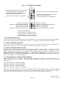
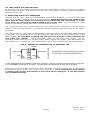
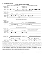
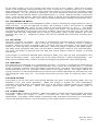
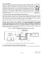
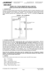
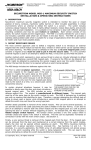
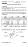
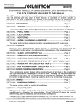
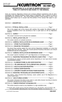
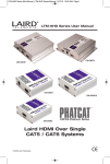
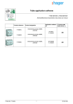
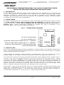
Securitron Magnalock Corp. Tel 800.624.5625 www.securitron.com [email protected] ASSA ABLOY, the global leader in door opening solutions SECURITRON TIMEMASTER MODEL TM-2 MULTI FUNCTION TIMER INSTALLATION AND OPERATING INSTRUCTIONS 1. DESCRIPTION The TimeMaster is an industrial quality multi-function timer that operates on 12 or 24 volts, AC or DC. Its outputs are 5 Amp DPDT relay contacts and a unique flashing voltage output described in section 5. Delay time is set in seconds or minutes up to a maximum of 255 minutes. While developed for the security industry, its comprehensive range of features makes it suitable for broad use in many applications. 2. TIMER POWER The timer is powered by 12 or 24 volts AC or DC on the power input terminals shown in Figure 1. If DC power is used, correct polarity must be followed. The timer is factory set to operate on 24 volts. If 12 volts is supplied, the H/L Dip Switch must be set to the "L" position (on). Power consumption depends on whether the relay is energized or not. Maximum draw is 100 mA at 12 or 24 volt operation. FIG. 1: TIMEMASTER OVERVIEW DIP SWITCHES +DC OR AC POWER INPUT C + NO - DC OR AC POWER INPUT TRIGGERS TIMER WHEN CONNECTED TO "+" TERMINAL T RESETS TIMER WHEN CONNECTED TO "+" TERMINAL R FLASH OUT SWITCHES NEG TO USER MOUNTED LED (FOLLOWS BOARD LED) F RELAY NC C NO 5 AMP DPDT RELAY OUTPUT NC LED 3. TIME SETTING One of the outstanding features of the TimeMaster is that the delay is set digitally instead of by a pot. This permits accurate time setting without the need for trial and error which is a lengthy process with the longer time ranges. 2 time ranges are possible: 1-255 seconds or 1-255 minutes. The unit is factory set for the seconds range. If you require minutes, a Dip Switch must be changed (see section 4.1). The exact time is then set from the 8 position Dip Switch which displays binary numbers from 1 to 128. If you turn an individual switch on, the time will be set for that exact value. Turning more than one switch on adds the value of the switches selected. By combining the switches as necessary, any exact value between 1 and 255 can be set. To quickly calculate the switches to turn on, start with turning on the largest value less than the time you want to set. Then subtract the value you turned on from the time you want and turn on the next largest value switch. Continue this process until you have exactly set the required time. For example, if you require 53 seconds, first turn on the Dip Switch marked 32 (the largest value under 53). Subtracting 32 from 53 yields 21. Then turn on the Dip Switch marked 16. Subtracting 16 from 21 yields 5. Turn on the Dip Switch marked 4 and then the one marked 1. You will have 4 switches on: 32, 16, 4 and 1. These numbers add to 53. © Copyright, 2011, all rights reserved Page 1 PN# 500-16000 Rev. C, 04/11 FIG. 2: DIP SWITCH SETTING DIP SWITCHES 1 2 3 4 5 6 7 8 TIME SET IN SECONDS NORMALLY OPEN TRIGGER SWITCH MODE SETTING MATRIX MODE SETTING MATRIX INPUT VOLTAGE SET FOR 24 VOLTS DIP SWITCH FACTORY SETTINGS SHOWN RESET OR REPOWER THE UNIT AFTER ANY DIP SWITCH CHANGE OR THE CHANGE MAY NOT BE READ 0N OFF FIRST 8 SWITCHES ARE FOR TIME SETTING 1 2 TURNING INDIVIDUAL SWITCHES ON 4 ADDS BINARY NUMBER SHOWN TO SET 8 TIME IN SECONDS OR MINUTES. 16 32 THE FACTORY SETTING IS 7 SECONDS. 64 128 TIME SET IN MINUTES NORMALLY CLOSED TRIGGER SWITCH MODE SETTING MATRIX MODE SETTING MATRIX INPUT VOLTAGE SET FOR 12 VOLTS 1 2 3 4 5 MODE SETTING MATRIX: SW3 ON; SW4 ON: ON DELAY MODE SW3 OFF; SW4 ON: ONE SHOT MODE SW3 ON; SW4 OFF: TOGGLE MODE SW3 OFF; SW4 OFF: OFF DELAY MODE 4. DIP SWITCH SETTING There are a total of 13 Dip Switches on the TimeMaster. The first 8 marked with binary numbers are for time setting and are explained in section 3. The next 5 select functions as follows: 4.1 SW1: TIME UNIT SETTING In the factory set condition (off), the time value set on the 8 time setting Dip Switches is expressed in seconds. Turning the switch on allows time setting in minutes. 4.2 SW2: TRIGGER SWITCH LOGIC Several of the operating modes (off delay, toggle and pulse output) require triggering from an external switch. The switch connects the trigger terminal (T) to the board's "+" terminal. In the factory set position of SW2 (off), a normally open external switch is used for triggering so that when terminal T is closed to terminal "+", the timer is triggered. Turning the switch on permits the use of a normally closed external switch. When the connection between terminal T and "+" is broken, the unit is triggered. 4.3 SW3 AND SW4: MODE SETTING MATRIX These switches are set in a matrix yielding 4 different operating modes for the TimeMaster. The factory set position is on delay. The modes are described in detail in section 6. The matrix settings are: SW3 SW3 SW3 SW3 ON; SW4 ON: ON DELAY MODE OFF; SW4 ON: ONE SHOT MODE ON; SW4 OFF: TOGGLE MODE OFF; SW4 OFF: OFF DELAY MODE The TM-2 actually provides 7 different operating modes with methods other than Dip settings being used to establish the other 3. Make sure you read the description of your mode in Section 6 as the setting of Dip Switches 3 and 4 is only part of the mode selection process. Page 2 PN# 500-16000 Rev. C, 04/11 4.4 SW5: INPUT VOLTAGE SETTING In the factory set (off) position this switch selects 24 volt (high) operation. Turning it on selects 12 volt (low) operation. If the switch is in the "on" (low) position, the timer can be damaged if operated on 24 volts. 5. RESET AND FLASH OUT TERMINALS Terminal R is for reset. When it is momentarily connected to terminal "+", the unit resets and goes into a condition equal to when it is first powered. When Dip Switches are changed, the timer must be reset, either via terminal R or by unpowering and repowering it. If this is not done, the changed Dip Switch settings may not be read. The reset function is also useful to terminate a timing cycle early from an external switch. The F terminal (flash out) permits connection of an external LED. See Figure 3 for the proper way to connect an external LED. The external LED will operate in the same way as the LED on the board. The LED provides a unique type of annunciation which depends on the operating mode selected for the unit. For the modes which include timing, the LED will flash at an increasing rate as the delay expires. An externally mounted LED can therefore provide a visual indication for how much time remains. This is particularly useful for the longer time ranges. For the operating modes which do not include timing (pulse output and toggle), the LED follows the relay status. It is on when the relay is energized. This is also a useful external visual indication. FIG. 3: FLASH OUT CONNECTIONS TO EXTERNAL LED RESISTOR RESISTOR T LED R F LED AC CONNECTION DC CONNECTION DIODE RESISTOR VALUE MUST BE CALCULATED TO SUIT INPUT POWER AND LED TYPE. IF THE TIMEMASTER IS POWERED FROM A DC SOURCE, USE THE CONNECTIONS SHOWN AT THE LEFT. IF IT'S POWERED FROM AN AC SOURCE, A DIODE MUST BE ADDED AS SHOWN ON THE RIGHT. When the time is set to zero in the cyclic mode, the flash out can be employed as an LED flasher to annunciate some condition on a panel (see section 6.5). The F terminal can only operate a resistive load of less than 60 mA or the board will be damaged. It can not operate any incandescent lamp. Page 3 PN# 500-16000 Rev. C, 04/11 6. OPERATING MODES FIG. 4: TIMING LOGIC CHARTS ON DELAY (SW3 ON; SW4 ON; SW2 ON) CONTROL POWER ON OFF OUTPUT ON RELAY OFF CYCLIC (JUMPER INSTALLED) CONTROL ON POWER OFF OUTPUT ON RELAY OFF TIME TIME TIME TIME TRIGGERED ON DELAY (SW3 ON; SW4 ON; SW2 OFF) CONTROL POWER ON OFF TRIGGER ON OFF OUTPUT ON RELAY OFF RESET TIME TIME TIME ON OFF OFF DELAY (SW3 OFF; SW4 OFF) CONTROL POWER ON OFF SECOND OPERATION OF RELAY SHOWS RETRIGGERING TRIGGER ON OFF OUTPUT ON RELAY OFF TIME TIME ONE SHOT (SW3 OFF; SW4 ON) CONTROL POWER ON OFF SECOND OPERATION OF RELAY SHOWS NON-RETRIGGERING TRIGGER ON OFF OUTPUT ON RELAY OFF TIME TIME PULSES (SW3 OFF; SW4 OFF, TIME SET TO ZERO) CONTROL POWER ON OFF CONTROL POWER TRIGGER ON OFF OUTPUT ON RELAY OFF TOGGLE (SW3 ON; SW4 OFF) ON OFF TRIGGER ON OFF 1/5 SEC. OUTPUT ON RELAY OFF 6.1 ON DELAY On delay functions as follows: When the timer is first powered, the delay begins with the relay deenergized. When the delay expires, the relay energizes and stays energized until power is removed from the timer. The unit is then ready for the next operation. The on delay function is considered "self triggering" and the "T" (trigger) terminal is not used. If the unit is unpowered and repowered before the delay expires, the time restarts without the relay energizing. To call up the on delay mode, Dip Switch 2 must be turned on (it is factory set off). This is an additional step to having set Dip Switches 3 and 4 on. This makes the unit self triggering as it "looks" for an open circuit between "T" and "+". If Dip Switch 2 is left off, you will get the somewhat different mode described in the next section. Page 4 PN# 500-16000 Rev. C, 04/11 In the other modes, you use a trigger input from an N.O. or N.C. switch. Since the on delay mode is self triggering and begins when the timer is powered, it appears that only a normally open switch can be used. There is a way around this however if you have only a normally closed signal available. The "R" terminal is employed. The timer should be powered continuously with the normally closed external switch connected between "+" and R. With the board in continuous reset, it will not start timing. When the switch opens, it will be as if the board was just powered and it will go through its on delay cycle until the switch closes again putting the board into reset. 6.2 TRIGGERED ON DELAY Triggered on delay differs from standard on delay in that a momentary trigger latches in the on delay function. To set up triggered on delay, Dip switches 3 and 4 are turned on and Dip Switch 2 is turned off. Then, an N.O. switch is connected between "T" and "+". The board should be continuously powered and when the trigger first closes , the delay period will begin. Successive operations of the trigger will have no effect. When the unit times out, the relay will energize and will stay energized until a second momentary switch closes between the reset terminal ("R") and "+". Triggered on delay can only be initiated and reset from normally open switches. 6.3 OFF DELAY Off delay functions as follows: The timer is continuously powered and an external switch is closed to trigger the function. This is done by connecting the "+" terminal to the T (trigger) terminal. Once the trigger is closed to the + terminal, the relay energizes. If the trigger is left closed, the relay will stay energized indefinitely. Once the trigger is opened, the delay begins. The relay stays energized until time out and then it deenergizes ready for the next operation. The term "off delay" is derived from the fact that timing begins when the trigger is opened (turned off). If the trigger is closed and opened again during the delay, the relay will stay energized but the time set will begin again. This aspect of the off delay function is called retriggerability. The delay can be extended any number of times by retriggering without the relay deenergizing. 6.4 ONE SHOT One shot can be considered non-retriggerable off delay. The timer is continuously powered and an external switch is closed to trigger the function. This is done by connecting the "+" terminal to the T (trigger) terminal. Once the trigger is closed to the + terminal, the relay energizes and deenergizes after time out regardless of the state of the trigger switch. The trigger switch can remain closed or can be switched during the timing cycle without affecting the fact that the relay will deenergize after time out. The switch must then go from open to closed to start a new cycle. 6.5 PULSE OUTPUT If the time is set for zero (all 8 time setting switches off) when in the off delay mode, the unit becomes a one shot pulse generator. When the trigger is closed, the relay immediately energizes and deenergizes 1/5 second later even if the trigger remains closed for an indefinite time longer than the pulse. When the trigger opens and closes again another pulse is generated. 6.6 TOGGLE MODE The toggle mode functions as follows: When the trigger is closed, the relay energizes and stays energized. When the trigger is closed a second time, the relay deenergizes and stays deenergized. The toggle mode creates a ratcheting relay and allows conversion of a momentary input to an alternate output. The time setting in the toggle mode is not functional. Page 5 PN# 500-16000 Rev. C, 04/11 4 5 6.7 CYCLIC MODE The cyclic mode is rarely used and is set up by a field soldering operation. BOTTOM OF DIP Install a wire jumper across the two pads shown to the right. With the jumper SWITCH BLOCK installed, the state of Dip Switches 2, 3 and 4 do not matter. The cyclic mode operates as follows: When the unit is powered, the relay energizes and deenergizes back and forth with the time between state changes controlled by the time setting Dip Switches. The cyclic mode is self triggering (when the unit is powered). If the time is set to zero (all 8 time setting switches off) the relay operates at 5 times per second allowing creation of a flashing light on a panel for instance. Use as a flasher rapidly wears the relay so that after several hundred hours of operation, the relay may fail. In flasher use, it is best to employ the flash out function (terminal F) to operate an external LED. This is CONNECT THESE TWO PADS BY described in section 5. WIRE JUMPER 7. USE OF THE MOV (INDUCTIVE KICKBACK PROTECTION) Note that a loose electronic component has been furnished with the TimeMaster. This is a metal oxide varistor (MOV). Its purpose is to absorb inductive kickback if the TimeMaster's relay is used to control an inductive load. When an inductive load is switched off by the relay, it emits a high voltage spike in reverse polarity (kickback). This will considerably shorten the life of the relay contacts and may also cause inconsistent operation of the TimeMaster owing to electronic noise from the kickback interfering with the TimeMaster's microprocessor. Inductive loads possess coils and generally include any electromagnetic device such as solenoids, motors or electric locks. Installation of the MOV consists of attaching it in parallel across the power input wires of the inductive load. The MOV is suitable for any inductive load that operates from 12 to 24 volts AC or DC. If the TimeMaster is being used to control a high voltage device with its own high voltage power supply, the MOV must not be used as it will burn out. Note that if Securitron's Magnalock is being controlled by the TimeMaster, the MOV is not necessary as the Magnalock has internal kickback protection. The drawing below shows typical wiring which employs an inductive load, the MOV, a trigger switch and the TimeMaster with its power supply. FIG. 5: TYPICAL TIMEMASTER WIRING WITH USE OF MOV DIP SWITCHES 12-24 V AC OR DC POWER SUPPLY NC C NO T R F RELAY MOV INDUCTIVE LOAD NC C NO LED TRIGGER SWITCH IN THIS CIRCUIT, THE LOAD TURNS OFF WHEN THE TIMEMASTER RELAY ENERGIZES 8. MAGNACARE LIFETIME REPLACEMENT WARRANTY For warranty information visit www.securitron.com/en/site/securitron/About/MagnaCare-Warranty/ Page 6 PN# 500-16000 Rev. C, 04/11