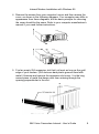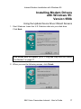
1
56K Voice Faxmodem Internal User’s Guide PN 1.024.1644-00 This manual covers installation and operating instructions for the following 3Com U.S. Robotics modem: 56K* Voice Faxmodem Internal * IMPORTANT! In accordance with the ITU standard for V.90 transmissions, this modem is capable of 56 Kbps downloads. However, the download speeds you experience may be lower due to varying line conditions and other factors. Uploads from users to server equipment travel at speeds up to 31.2 Kbps. An analogue phone line compatible with the ITU V.90 standard or 3Com’s proprietary 56K technology, and an Internet provider or corporate host site with the ITU V.90 standard or 3Com’s proprietary 56K technology are necessary for these high-speed downloads. The ITU V.90 standard was officially determined in February, 1998 and is expected to be ratified in September, 1998. See www.3com.com/56k for details. The material contained in this document is for information purposes only and is subject to change without notice. 3Com makes no representations or warranties with respect to the contents hereof and specifically disclaims any implied warranties of merchantability or fitness for any particular purpose. No part of this document may be reproduced, transmitted, transcribed, or stored in a retrieval system in any form or by any means, mechanical, magnetic, electronic, optical, chemical or otherwise, without the written permission of 3Com. 3Com assumes no responsibility for errors or omissions in this manual. Nor does 3Com make any commitment to update the information contained herein. 3Com, the 3Com logo, and U.S. Robotics are registered trademarks of 3Com Corporation or its subsidiaries. Windows is a registered trademark of Microsoft Corp. Any other trademarks, trade names, service marks, or service names owned or registered by any other company and used in this manual are the property of their respective owners. Copyright 1998 3Com Corporation or its subsidiaries All rights reserved. Table of Contents WELCOME TO 56K INFORMATION ACCESS......................................1 PRODUCT FEATURES .......................................................................2 INTERNAL MODEM INSTALLATION WITH WINDOWS 95...................5 DETERMINING AVAILABLE RESOURCES ....................................................5 DETERMINING YOUR VERSION OF W INDOWS 95.........................................6 PLUG AND PLAY INSTALLATION ............................................................7 HOW TO PREPARE FOR PLUG AND PLAY INSTALLATION .............................7 HOW TO INSERT THE MODEM INTO THE COMPUTER .....................................8 INSTALLING MODEM DRIVERS WITH W INDOWS 95: Versions 950 and 950a (Moving Through the “New Hardware Found” Screens)................................... 12 Version 950b (Using the Update Device Driver Wizard Screens) .... 16 INTERNAL MODEM INSTALLATION WITH WINDOWS 3.X ............... 20 A Word about COM Ports and IRQs ............................................ 20 How to Change the Modem’s Settings .......................................... 21 How to Insert the Modem into the Computer ................................. 23 SOFTWARE INSTALLATION ........................................................... 29 W INDOWS 95.................................................................................. 29 W INDOWS 3. X................................................................................. 29 TYPE OF MODEM.............................................................................. 30 INITIALISATION STRING ...................................................................... 30 FLOW CONTROL.............................................................................. 30 TROUBLESHOOTING ...................................................................... 31 SUPPORT RESOURCES .................................................................. 39 ARE YOU STILL HAVING PROBLEMS?................................................... 40 IF YOU MUST RETURN THE MODEM TO US ............................................. 40 GLOSSARY..................................................................................... 41 Table of Contents TECHNICAL REFERENCE ................................................................ 51 TYPING COMMANDS.......................................................................... 51 BASIC DATA COMMANDS .................................................................. 51 EXTENDED DATA COMMANDS ............................................................. 57 S-REGISTERS.................................................................................. 64 FAX COMMANDS ............................................................................. 71 THE SERIAL INTERFACE (CABLE INFORMATION) ....................................... 73 REGULATORY (CE COMPLIANCE)................................................... 74 ELECTROMAGNETIC COMPATIBILITY ...................................................... 74 RINGER EQUIVALENCE NUMBER........................................................... 74 LIMITED WARRANTY...................................................................... 75 Welcome to 56K*Information Access The International Telecommunications Union (ITU) decides the technical protocols that communications devices must use to operate with each other. Modems that comply with ITU standards can “talk” to other standards-compliant modems and fax machines worldwide. The ITU has determined a worldwide standard for 56K modem technology. With a U.S. Robotics modem, you can get 56K Internet access from any service provider who offers the ITU V.90 standard or 3Com’s proprietary 56K technology. 3Com is working with providers everywhere to quickly upgrade their service to the ITU V.90 standard. ∗ In accordance with the ITU standard for V.90 transmissions, this modem is capable of 56 Kbps downloads. However, the download speeds you experience may be lower due to varying line conditions and other factors. Uploads from users to server equipment travel at speeds up to 31.2 Kbps. An analogue phone line compatible with the ITU V.90 standard or 3Com’s proprietary 56K technology, and an Internet provider or corporate host site with the ITU V.90 standard or 3Com’s proprietary 56K technology are necessary for these high-speed downloads. The ITU V.90 standard was officially determined in February, 1998 and is expected to be ratified in September, 1998. See www.3com.com/56k for details. 56K Voice Faxmodem Internal - User’s Guide 1 Product Features Modulation Schemes ITU-T V.90 x2™ technology (Download up to 56kbps, and Upload using V.34) ITU-T V.34+ ITU-T V.34 ITU-T V.32bis ITU-T V.32 ITU-T V.23 ITU-T V.22bis ITU-T V.22 Bell 212A ITU-T V.21 Bell 103 Error Control and Data Compression Schemes ITU-T V.42 ITU-T V.42bis MNP 2-5 Fax Modulation Schemes ITU-T V.17 ITU-T V.29 ITU-T V.27ter ITU-T V.21 Fax Standards EIA 578 Class 1 FAX EIA 592 Class 2.0 FAX Front Channel Link Rates (Download Speeds) 28000, 29333, 30666, 32000, 33333, 34666, 36000, 37333, 38666, 40000, 41333, 42666, 44000, 45333, 46666, 48000, 49333, 50666, 52000, 53333, 54666, 56000, 57333 2 56K Voice Faxmodem Internal - User’s Guide Product Features Back Channel Link Rates (Upload Speeds) 4800, 7200, 9600, 12000, 14400, 16800, 19200, 21600, 24000, 26400, 28800, 31200 V.34+ Link Rates 4800, 7200, 9600, 12000, 14400, 16800, 19200, 21600, 24000, 26400, 28800, 31200, 33600 V.32bis Link Rates 4800, 7200, 9600, 12000, 14400 Additional Link Rates 300, 1200/75 (V.23), 1200, 2400 Fax Link Rates 2400, 4800, 7200, 9600, 12000, 14400 56K Voice Faxmodem Internal - User’s Guide 3 Product Features Flash ROM Upgradable 56K Voice Faxmodem Internal supports software download through flash memory. You can obtain the latest features by downloading updates quickly and easily. Speakerphone* With the addition of an inexpensive set of externally powered speakers, your new voice modem provides all the convenience of a full-duplex speakerphone. Unlike many half-duplex speakerphones, your modem allows you to converse normally without annoying echoes and distortion. Simply plug the speakers and microphone into the jacks on the modem identified with the appropriate icons, and you are ready to go. Personal Voice Mail* Personal Voice Mail turns your modem into a full-featured messaging system. Enjoy the convenience of professional voice mail in your home or office for a fraction of the cost. With Personal Voice Mail, you can record custom greetings, receive messages, and set up multiple voice “mailboxes”. You can even access your voice messages remotely. Your modem will automatically detect incoming fax/voice/data calls and route them appropriately. * A headset, external powered speakers, or sound card (with audio cable) is required to utilise all voice features, including hands-free speakerphone. 4 56K Voice Faxmodem Internal - User’s Guide Internal Modem Installation with Windows 95 Before you start your installation, make sure that you have the following items: Modem U.S. Robotics Disk RJ-11 Phone Lead Tail Lead Microphone Analogue (Standard) Telephone Wall Socket Phillips Head Screwdriver or ¼” Hex Screwdriver Data/Fax/Voice Communications Software and Manual Determining Available Resources Your U.S. Robotics modem is a Plug and Play device. Windows 95 can automatically identify a Plug and Play device and determine if your system has the resources necessary to support the device. However, Plug and Play will not work if you do not have resources available or if devices on your system are not reporting resource usage correctly. Here is how you can verify that your system has the necessary resources before installing the modem. 1. Click the Windows 95 Start button, point to Settings, and then click Control Panel. 2. Double-click the System icon. 3. When the “System Properties” screen appears, click the Device Manager tab. 4. Double-click Computer and the “Computer Properties” screen appears. 5. Select the option at the top of the screen to show Interrupt Requests (IRQs). 56K Voice Faxmodem Internal - User’s Guide 5 Internal Modem Installation with Windows 95 You will see the IRQs your system is currently using. If IRQs 3, 4, 5, and 7 are being used, you need to free an IRQ before you begin installation. This process involves moving a device from the IRQ you want to use to a different (and usually higher) IRQ setting. Please read the documentation for (or contact the manufacturer of) the device that is currently using the IRQ you want to use for your modem, to learn more about what you should do to move the other device. Determining Your Version of Windows 95 Follow these steps to determine your version of Windows 95. This information will be important during installation. 1. Click the My Computer icon on your desktop with the right mouse button. 2. Click Properties. 3. In the “System Properties” screen, look at the system information under the General tab (circled in the following screen image). The number following the text “Microsoft Windows 95” will end with “950”, “950a”, or “950b”. This indicates your version of Windows 95. Windows 95 version Write down your version of Windows. Windows 95 version _______ Click OK. 6 56K Voice Faxmodem Internal - User’s Guide Internal Modem Installation with Windows 95 Plug and Play Installation This modem’s factory default setting is “Plug and Play” operation. If you are using the Windows 95 environment, the COM port and IRQ will automatically be set to Windows as the environment. Since your new U.S. Robotics modem is a “Plug and Play” device, Windows 95 may be able to detect your modem automatically after you plug it into your computer. The operating system should do all the work of recognising the modem for you. How to Prepare for Plug and Play Installation 1. Touch an unpainted metal part of your computer (the back is usually unpainted) to discharge static electricity. Static can damage your modem. 2. Take the modem out of its plastic bag. 5.3.Find the jumper shunts (small black plastic pieces) on the COM (serial) port and IRQ jumper pins on your modem. They should be in roughly the area indicated in the following illustration. 56K Voice Faxmodem Internal - User’s Guide 7 Internal Modem Installation with Windows 95 4. When doing a “Plug and Play” installation, the jumper shunts should be placed so that they are hanging from single jumper pins rather than on pairs of pins. Move your jumper shunts so they are hanging as in the diagram. If you need to move the jumper shunts, grasp them with tweezers or needle-nosed pliers. DO NOT grasp too firmly, however, or you may crush the jumper shunts. If a jumper shunt seems stuck, try gently rocking it back and forth as you lift. How to Insert the Modem into the Computer 1. Before installing your modem, write down your modem's serial number. The serial number is on the white label under the bar code on the modem and on the outside of the box. Serial Number_______________________ Before you unplug any cords, label them or make a sketch of how they are connected. This can be helpful when you plug them back in later. 2. Turn off your computer and unplug it from the electrical outlet. 2.3.Unplug any peripheral devices (printer, monitor, keyboard, mouse, etc.) from the computer. CAUTION: To avoid risk of electric shock, make sure your computer and all peripheral devices are turned off and unplugged from electrical outlets. 8 56K Voice Faxmodem Internal - User’s Guide Internal Modem Installation with Windows 95 4. Remove the screws from your computer’s cover and then remove the cover, as shown in the following diagrams. Your computer may differ in appearance from these diagrams, but the basic principle for removing the cover should be the same. Refer to your computer manufacturer’s manual if you need further instructions. 5. Find an empty ISA expansion slot that’s at least as long as the gold edge of your modem. (ISA slots are dark plastic grooves lined with metal.) Unscrew and remove the expansion slot cover. It is the long narrow piece of metal that keeps dust from entering through the opening perpendicular to the slot. 56K Voice Faxmodem Internal - User’s Guide 9 Internal Modem Installation with Windows 95 6. Holding the modem by each corner, align the gold edge with the empty expansion slot. Push down gently until the modem snaps into the slot. The diagram shows horizontally aligned expansion slots. Some computers have vertically aligned slots. The instructions apply to both styles. You need to apply a little pressure to seat the modem properly. Sometimes a gentle back and forth motion helps fit the modem all the way into the slot. If you feel resistance, the modem may not be properly lined up with the slot. Do not force it into the slot. Remove the modem and try again. 7. Once the modem is inserted, fasten it firmly into place using the screw that you removed in step 5. 8. Replace the computer’s cover and fasten it with the screws you removed in step 4. 9. Locate the phone wall socket you plan to use for the modem. If you have a phone plugged into this wall socket, disconnect the telephone cord from the socket. The phone wall socket you use must be for an ANALOGUE phone line (the type found in most homes). Many office buildings have digital phone lines. Be sure you know which type of line you have. The modem will be damaged if you use a digital phone line. 10. Plug one end of the phone cord included with the modem into the TELCO socket. 11. Plug the other end of the cable into the phone wall socket. 10 56K Voice Faxmodem Internal - User’s Guide Internal Modem Installation with Windows 95 56K Voice Faxmodem Internal - User’s Guide 11 Internal Modem Installation with Windows 95 You cannot use the modem and a phone at the same time if they share the same telephone line. If you want to use a telephone on the same line as the modem when the modem is not in use, plug your telephone cord into the modem’s PHONEsocket, using the supplied Tail Lead Adaptor. 12. An external, powered speaker must be connected for speakerphone and voice mail usage. Plug a set of powered, magnetically-shielded, external speakers or a headset (not included) into the 3.5 mm SPKR socket on the modem. 2. 13. Plug the supplied microphone into the 3.5 mm MIC socket on the modem. 14. Plug the power cords, cables, and peripherals back into the computer and turn on the computer. 15. Start Windows 95. 12 56K Voice Faxmodem Internal - User’s Guide Internal Modem Installation with Windows 95 Installing Modem Drivers with Windows 95: Versions 950 and 950a Moving Through the “New Hardware Found” Screens 1. When Windows 95 starts, it should detect the modem. If it does, you will see the following screen. Click Driver from disk provided by hardware manufacturer. Then click OK. If this screen does not appear, go to “If Plug and Play Does Not Detect Your Modem” on page 37. 2. When you see the Install from Disk screen, insert the disk or the CDROM and type A:\ or D:\ If your disk drive or CD-ROM drive is a different letter, type that letter instead of A or D. Click OK. Windows will load the modem’s drivers. 56K Voice Faxmodem Internal - User’s Guide 13 Internal Modem Installation with Windows 95 3. Once Windows finishes loading the information from the disk, verify that the modem installation was a success. When your desktop returns, click the Windows Start button and point to Settings. Then click Control Panel. 4. Double-click the Modems icon (circled in the screen image below). 14 56K Voice Faxmodem Internal - User’s Guide Internal Modem Installation with Windows 95 5. In the “Modems Properties” screen, you should see a description for your modem. This means the installation was a success. Click OK. If you do not see your modem listed in the preceding screen, the Plug and Play installation was unsuccessful. Please refer to “If Plug and Play Does Not Detect Your Modem” on page 37. 6. Next, click the Diagnostics tab at the top of the “Modems Properties” screen. Write down the COM setting for your modem in the space below. Your screen may show a different setting than that shown in the following screen. You will need to know this setting when you install your communications software. COM Port___________ 56K Voice Faxmodem Internal - User’s Guide 15 Internal Modem Installation with Windows 95 6. Click More Info…. Click OK. Turn to “Software Installation” on page 29 for information about installing communications software. 16 56K Voice Faxmodem Internal - User’s Guide Internal Modem Installation with Windows 95 Installing Modem Drivers with Windows 95: Version 950b Using the Update Device Driver Wizard Screens 1. Start Windows. Insert the U.S. Robotics disk into your disk drive. Click Next. If this screen does not appear, go to “If Plug and Play Does Not Detect Your Modem” on page 37. 2. When you see the following screen, click Finish. 56K Voice Faxmodem Internal - User’s Guide 17 Internal Modem Installation with Windows 95 3. Now you should verify that the modem installation was a success. When your desktop returns, click the Windows Start button and point to Settings. Then click Control Panel. 4. Double-click the Modems icon (circled in the screen image below). 18 56K Voice Faxmodem Internal - User’s Guide Internal Modem Installation with Windows 95 5. In the “Modems Properties” screen, you should see a description of your modem. This means the installation was a success. Click OK. If you do not see your modem listed in the preceding screen, the Plug and Play installation was unsuccessful. Please refer to the “If Plug and Play Does Not Detect Your Modem” section on page 37. 6. Next, click the Diagnostics tab at the top of the “Modems Properties” screen. Write down the COM setting for your modem in the space. Your screen may show a different setting than that shown in the following screen. You will need to know this setting when you install your communications software. COM Port_________ 56K Voice Faxmodem Internal - User’s Guide 19 Internal Modem Installation with Windows 95 7. Click More Info…. Click OK. Turn to “Software Installation” on page 29 for information about installing communications software. 20 56K Voice Faxmodem Internal - User’s Guide Internal Modem Installation with Windows 3.x Before you start your installation, make sure that you have the following items: Modem U.S. Robotics Disk RJ-11 Phone Lead Tail Lead Microphone Analogue (Standard) Telephone Wall Socket Phillips Head Screwdriver or ¼” Hex Screwdriver Data/Fax/Voice Communications Software and Manual A Word about COM Ports and IRQs Most computer accessories — a mouse, sound card, enhanced graphics card, scanner, etc. — require a special connection through which they can communicate with the computer. For an internal modem, this connection is called a communications (or COM) port. Most computers have 1 or 2 COM ports, but they can have up to 4. Although internal modems do not connect to COM ports directly, they do require a COM port setting, which is determined by the setting on the modem’s COM jumper pins. Each COM port uses an interrupt request (IRQ). An accessory uses an IRQ to get the attention of your computer’s central processing unit (CPU) so that the accessory can perform a task. The computer stops what it is doing, depending on the priority of the request, to help the accessory perform its task. When two accessories share an IRQ, it is like two people asking different questions in unison to a third person. Just as the person being asked the two questions cannot understand either request, a computer can lock up or otherwise fail to communicate properly with your modem when there is an IRQ conflict. 56K Voice Faxmodem Internal - User’s Guide 21 Internal Modem Installation with Windows 3.x Accessories cannot share COM ports and should not share IRQs. When accessories try to share settings, they will either not work properly or not work at all. 3Com has set your modem to a default Plug and Play setting geared towards Windows 95 users. In this configuration, the shunts used to set your modem’s COM port and IRQ settings are hanging from single jumper pins and will not affect your modem’s settings Some communications software programs require a particular setting for your modem. Now is a good time to read the software’s manual to determine what setting is required. How to Change the Modem’s Settings 1. Always touch an unpainted metal part of your computer (the back is usually unpainted) to discharge static electricity before handling the modem. Static can damage your modem. 2. Take the modem out of its plastic bag. 3. Find the COM and IRQ jumper shunts (small black plastic pieces) on your modem’s jumper pins (refer to the diagram). 22 56K Voice Faxmodem Internal - User’s Guide Internal Modem Installation with Windows 3.x The jumper shunts will be hanging from single jumper pins as shown in the following illustration. 4. To change the COM port and IRQ settings, you need to reposition the jumper shunts on the COM port and IRQ pins. To do this, lift the jumper shunts off the pins. Grasp the jumper shunts with a tweezers or needle-nosed pliers. DO NOT grasp too firmly, as you may crush the shunts. If a jumper shunt seems stuck, gently rock it back and forth as you lift. Do not touch any other part of the modem or your computer with the tweezers/pliers. A shunt needs to be sitting on both jumper pins in order to effectively set the modem to the desired setting. 5. Move the jumper shunt to the new setting. • The COM port setting can involve one to three shunts. The four possible COM port settings are as follows: • Unlike most COM port settings, the IRQ setting involves only one jumper shunt. Simply move the jumper shunt to the pins labelled with the IRQ you need. 56K Voice Faxmodem Internal - User’s Guide 23 Internal Modem Installation with Windows 3.x The following are recommended combinations of COM port and IRQ settings when not using Plug and Play: COM 1, IRQ 4 or COM 2, IRQ 3 Most computers provide you with COM1 and COM2. If you do not use either of these two ports, you may disable them either in your computer's BIOS or with jumpers (refer to the manual of your PC). Any device attached to a disabled COM port will not be useable anymore, so it is advisable to check your computer's configuration thoroughly before proceeding. Generally the serial mouse is on COM1. COM3 and COM4 may also be used. It is not recommended to assign these ports an IRQ already used by another device, e.g. an active COM1 (IRQ4) or COM2 (IRQ3). If it is not possible to disable COM1 or COM2, you may use either IRQ5 or IRQ7. However, be aware that IRQ7 is generally used by the printer port LPT1 and may therefore not be available. (You may be able to disable this port, if it is not used.) You should also check if a sound card is installed in your PC, which usually is on IRQ5. A sound card can be reconfigured to use another IRQ, i.e. 10. Refer to your sound card manual. It is recommended that the modem be installed on COM2 whenever possible. How to Insert the Modem into the Computer 1. Before installing your modem, write down your modem's serial number. The serial number is on the white label under the bar code on the modem and on the outside of the box. Serial Number_______________________ Before you unplug any cords, label them or make a sketch of how they are connected. This can be helpful when you plug them back in later. 24 56K Voice Faxmodem Internal - User’s Guide Internal Modem Installation with Windows 3.x 2. Turn off your computer and unplug it from the electrical outlet. 2.3.Unplug any peripheral devices (printer, monitor, keyboard, mouse, etc.) from the computer. CAUTION: To avoid risk of electric shock, make sure your computer and all peripheral devices are turned off and unplugged from electrical outlets. 4. Remove the screws from your computer’s cover and then remove the cover, as shown in the following diagrams. Your computer may differ in appearance from these diagrams, but the basic principle for removing the cover should be the same. Refer to your computer manufacturer’s manual if you need further instructions. 56K Voice Faxmodem Internal - User’s Guide 25 Internal Modem Installation with Windows 3.x 5. Find an empty ISA expansion slot that’s at least as long as the gold edge of your modem. (ISA slots are dark plastic grooves lined with metal.) Unscrew and remove the expansion slot cover. It is the long narrow piece of metal that keeps dust from entering through the opening perpendicular to the slot. 6. Holding the modem by each corner, align the gold edge with the empty expansion slot. Push down gently until the modem snaps into the slot. The diagram shows horizontally aligned expansion slots. Some computers have vertically aligned slots. The instructions apply to both styles. You need to apply a little pressure to seat the modem properly. Sometimes a gentle back and forth motion helps fit the modem all the way into the slot. If you feel resistance, the modem may not be properly lined up with the slot. Do not force it into the slot. Remove the modem and try again. 26 56K Voice Faxmodem Internal - User’s Guide Internal Modem Installation with Windows 3.x 7. Once the modem is inserted, fasten it firmly into place using the screw that you removed in step 5. 8. Replace the computer’s cover and fasten it with the screws you removed in step 4. 9. Locate the phone wall socket you plan to use for the modem. If you have a phone plugged into this wall socket, disconnect the telephone cord from the socket. The phone wall socket you use must be for an ANALOGUE phone line (the type found in most homes). Many office buildings have digital phone lines. Be sure you know which type of line you have. The modem will be damaged if you use a digital phone line. 10. Plug one end of the phone cord included with the modem into the TELCO socket. 11. Plug the other end of the cable into the phone wall socket. You cannot use the modem and a phone at the same time if they share the same telephone line. If you want to use a telephone on the same line as the modem when the modem is not in use, plug your telephone cord into the modem’s PHONE socket, using the supplied Tail Lead Adaptor. 12. An external, powered speaker must be connected for speakerphone and voice mail usage. Plug a set of powered, magnetically-shielded, external speakers or a headset (not included) into the 3.5 mm SPKR socket on the modem. 12. 13. Plug the supplied microphone into the 3.5 mm MIC socket on the modem. 56K Voice Faxmodem Internal - User’s Guide 27 Internal Modem Installation with Windows 3.x 14. Plug the power cords, cables, and peripherals back into the computer and turn on the computer. 15. Start Windows 3.x. 16. If you have your modem set to COM1/IRQ4 or COM2/IRQ3, go to “Software Installation” on page 29. If you have your modem configured to any other setting, open Program Manager and double-click the Main icon. 17. Double-click the Control Panel icon. 18. Double-click the Ports icon. 19. If it is not already selected, click the COM port for your modem. Then click Settings. 28 56K Voice Faxmodem Internal - User’s Guide Internal Modem Installation with Windows 3.x 20. Set the Baud Rate to the highest option and Flow Control to Hardware. Then click Advanced. 21. In the Interrupt Request Line (IRQ) box, select the IRQ. 22. Click OK. 23. You will see a screen prompting you to restart Windows. Click Restart Now. Turn to “Software Installation” on page 29 for information about installing communications software. 56K Voice Faxmodem Internal - User’s Guide 29 Software Installation Voice Fax, Data, and Telecommunications Software (communications software) allows sending and receiving faxes directly from your computer desktop. You can build your own fax directory, send faxes to specified groups of fax numbers, select individual cover pages when necessary, and send individual faxes without exiting your word processing program. Communications software allows you to change settings and issue commands to your modem. Additionally, voice communications software lets you connect to Bulletin Board Systems (BBS) and other online data providers. Take advantage of this access to enter a new world of information and entertainment. Be sure to install software after the modem is installed. Windows 95 1. Insert the communications software disk into your disk drive. 2. Go to the Windows Start menu and select Run. 3. In the Run dialog box, type A:\setup.exe and press ENTER. If your disk drive is a different letter, enter that letter in place of A. 4. Follow the on-screen instructions to install your Voice Fax, Data, and Telecommunications Software. Windows 3.x 1. Insert the communications software disk into your disk drive. 2. In Program Manager, click File and select Run. 3. In the text box, type A:\setup.exe and press ENTER. If your disk drive is a different letter, type that letter instead of A. Then click OK. 4. Follow the on-screen instructions to install your Voice Fax, Data, and Telecommunications Software. 30 56K Voice Faxmodem Internal - User’s Guide Software Installation Refer to your software manual for the specific installation instructions. The software’s installation program will ask you questions about the modem you are using. You may need the following information when installing a communications software package. Type of Modem Most voice communications software programs will ask you to select the type of modem you are using. Select a U.S. Robotics high speed modem. If that selection is not listed, pick Courier Dual Standard, V.32bis, or V.34. Initialisation String For hardware flow control, a fixed serial port rate, and full result codes, type: AT&F1 and then press ENTER. If you must use software flow control, type: AT&F2 and then press ENTER. Flow Control For hardware flow control (highly recommended), select RTS/CTS. For software flow control, select XON/XOFF. You may need to disable the flow control (hardware or software) that you are not using. Congratulations! You are now ready to start using your 3Com U.S. Robotics modem. 56K Voice Faxmodem Internal - User’s Guide 31 Software Installation Read This First! 1. Click Windows Start, point to Settings, and click Control Panel. 2. Double-click the Modems icon. 3. Click the Diagnostics tab. 4. Click on the COM port that your modem is assigned to, so that it is highlighted. (If you do not see your modem on this screen, you will need to shut down your computer and uninstall the modem. Reinstall the modem following the instructions in the Installation Guide.) 5. Click More Info. You should see a list of the modem’s ATI commands. Click OK. (If you do not, your modem is not properly installed. Shut down your computer and uninstall the modem. Reinstall the modem following the instructions in the Installation Guide.) PROBLEM: The computer or software will not recognise the modem. POSSIBLE SOLUTION Make sure the modem turned on. An internal modem should turn on automatically when the computer is turned on. POSSIBLE SOLUTION You may not be entering modem commands in the proper manner. Type in all upper case (AT) or all lower case (at). 32 56K Voice Faxmodem Internal - User’s Guide Troubleshooting POSSIBLE SOLUTION You may have a COM port/IRQ conflict. If you have an internal modem and a Windows 95 system, right-click on the My Computer icon on your desktop. Click Properties. Click the Device Manager tab. If you see a yellow exclamation point over your modem, you have a resource conflict, and it is probably an IRQ conflict. Click the modem’s name to select it. Then click Remove. You will be asked if you are sure you wish to remove the device. Click OK. When the modem has been removed, shut down and turn off your computer. Unplug the computer from its electrical outlet and remove the cover. Physically remove the modem from its ISA slot. Replace the cover, plug the computer back into the electrical outlet, and turn on the computer. When Windows restarts, once again right-click the My Computer icon on your desktop and click Properties. Click the Device Manager tab. Double-click Computer. Make sure the “Interrupt request (IRQ)” radio button at the top of the screen is checked. You can determine which IRQ settings are free on your system by looking for numbers that are not listed in the Setting column. One of the following IRQs needs to be free: 3, 4, 5, or 7 (or 9 if you have a Winmodem). If there are no IRQ settings free in this range, you need to move a device off of one of these IRQs in order to free it for use by your modem. We recommend removing other modems or disabling COM ports that may be using one of these IRQs. After you have made these changes, reinstall the modem using the instructions in the Installation Guide. Once your modem is properly installed, make sure you have the correct COM port and IRQ settings in your software and/or in the Windows Device Manager. PROBLEM: The modem will not go off hook to dial or does not answer the phone. POSSIBLE SOLUTION You may have plugged your modem’s phone cord into a digital line. Plugging your modem’s phone cord into a digital phone line can damage the modem. Call your phone company if you are unsure whether or not your phone line is digital. 56K Voice Faxmodem Internal - User’s Guide 33 Troubleshooting POSSIBLE SOLUTION You may have plugged your modem’s phone cord into the wrong jack on the modem. Make sure the phone cord is plugged into a jack labeled with the word TELCO (marked with a wall jack icon on externals). POSSIBLE SOLUTION You might have a bad phone cord connection to your modem. The phone cord should be plugged into the TELCO jack on the modem (marked with a wall jack icon on externals) and the wall phone jack. The phone cord should be no longer than 12 feet in length. Use the phone cord included with your modem if possible. POSSIBLE SOLUTION Your phone jack may have been wired incorrectly. Contact your telephone company. Ask them to make sure the tip and ring are on the inside pair of wires. POSSIBLE SOLUTION You may have devices between the modem and the phone jack. There should be no line splitters, fax machines, or other devices between the modem and the wall jack. POSSIBLE SOLUTION You may have a poor line connection. Place the call again. Calls are routed differently each time. POSSIBLE SOLUTION If you have voice mail, your dial tone may be altered because messages are waiting. Retrieve your voice mail messages to restore your normal dial tone. POSSIBLE SOLUTION Your software may not have auto answer enabled. Enable the auto answer feature. In your communication software’s terminal mode, type ATS0=1 and press ENTER. You need to enable auto answer before every session unless you alter your software’s initialisation string to permanently enable auto answer. 34 56K Voice Faxmodem Internal - User’s Guide Troubleshooting PROBLEM: Both modems sound like they are exchange carrier signals, but fail to establish a connection. POSSIBLE SOLUTION You may have a poor line connection. Place the call again. Calls are routed differently each time. POSSIBLE SOLUTION Your phone jack may have been wired incorrectly. Contact your telephone company. Ask them to make sure the tip and ring are on the inside pair of wires. PROBLEM: Your 56K modem cannot achieve a 56K Internet connection. POSSIBLE SOLUTION This modem is capable of 56 Kbps downloads. However, the download speeds you experience may be lower due to varying line conditions and other factors. Uploads from users to server equipment travel at speeds up to 31.2 Kbps. An analogue phone line compatible with the ITU V.90 standard or 3Com’s proprietary 56K technology, and an Internet provider or corporate host site with the ITU V.90 standard or 3Com’s proprietary 56K technology are necessary for these high-speed downloads. Check http://www.3com.com/56k for a list of ISPs that observe the 56K ITU standard and/or offer 3Com’s proprietary 56K technology. POSSIBLE SOLUTION The phone lines in your area may not be 56K compatible. Call your phone company to find out if your phone line is compatible with the ITU standard for 56K and/or is compatible with 3Com’s proprietary 56K technology. POSSIBLE SOLUTION You may have devices between the modem and the phone jack. There should be no line splitters, fax machines, or other devices between the modem and the wall jack. 56K Voice Faxmodem Internal - User’s Guide 35 Troubleshooting PROBLEM: Errors are constantly occurring in your V.17 fax transmissions. POSSIBLE SOLUTION Your modem initialisation string may be insufficient for fax transmissions. In terminal mode, type the following initialisation string: AT&F&H3&I2&R2S7=90 and then press ENTER. The standard string for faxing is AT&F1S36=0 POSSIBLE SOLUTION There may be a Terminate and Stay Resident (TSR) program (such as a screen saver or virus scanner) running in the background, disrupting data communications. Disable any Terminate and Stay Resident (TSR) programs running in the background. If you have software running as a TSR, check the software’s manual for information about disabling its ability to operate as a TSR. POSSIBLE SOLUTION Your baud rate may be set too high. In your communications software, lower the baud rate to 9600, 7200, or 4800. POSSIBLE SOLUTION You may be trying to fax a compressed file. Decompress the file using the application with which it was compressed. Then open it in the application with which it was created. Select your fax software as the printer and then print the file. PROBLEM: Your communications software fails to initialise the modem. POSSIBLE SOLUTION Your software’s port settings may be incorrect. Make sure the software’s port settings match those for your modem. POSSIBLE SOLUTION Make sure the modem is turned on. An internal modem should turn on automatically when the computer is turned on. 36 56K Voice Faxmodem Internal - User’s Guide Troubleshooting 56K Voice Faxmodem Internal - User’s Guide 37 Troubleshooting PROBLEM: If Plug and Play does not detect your modem. You have installed the modem and Windows has restarted, but you see only your normal desktop. You do not see any screens indicating new hardware has been detected. POSSIBLE SOLUTION The Plug and Play installation was not successful. Try the following: 1. Click Windows 95 Start and click Shut Down. When asked if you wish to shut down your computer, click Yes. When Windows 95 indicates that it is safe to turn off your computer, turn it off and wait 15 seconds. Then turn the computer back on. Windows 95 may detect your modem upon this restart, even if it did not detect the modem during the initial installation. If you see screens indicating that new hardware has been detected by Windows 95, follow the on-screen instruction to install the modem. If you do not see the new hardware screens, continue with step 2 below. 2. Click Windows 95 Start, point to Settings, and click Control Panel. Double-click the System icon and then click the Device Manager tab on the “System Properties” screen. Look for “Other Devices” or “Unknown Devices” in the list that appears. If you do not see either of these options in the list, please contact our technical support department. If you do see one of these options, double-click the option. If the description that appears matches the modem you are trying to install, click Remove. Click OK when Windows asks if you wish to remove the device. Next, restart the computer and continue with the on-screen instructions. If the computer does not detect the modem after this second restart, please contact our technical support department. 38 56K Voice Faxmodem Internal - User’s Guide Support Resources Connecting to the 3Com Bulletin Board System (BBS) To connect to the 3Com BBS, dial 33320910308. If this is your first time connecting to our BBS, you will be asked to enter your name, create a password of your choice, and to fill out a questionnaire. Internet FTP The Internet FTP provides free library containing the same files as the BBS site. To access the FTP site type ftp.usr.com. Internet On Demand The Internet on Demand provides automatic technical support through a library containing product information, quick reference cards and installation help. To obtain an index of available documents, send a blank e-mail to [email protected]. To have a document e-mailed to you, place the document number in the subject field. World Wide Web A 3Com Home Page contains the same information as the Internet on Demand listing. To log on to our Web site, type http://www.3Com.com. CompuServe Through CompuServe access the same information as on the Internet FTP site. The 3Com forum address is GO THREECOM. America Online Go to the Keyword field and type 3COM to connect to the various 3Com resources, such as file libraries, message boards, online customer support, and product announcements. Fax and Technical Support Hotline Technical questions about 3Com modems can also be answered via fax or by technical support representatives. Hotline: +33 (0) 3 20 19 24 24 Fax: +33 (0) 3 20 19 24 34 56K Voice Faxmodem Internal - User’s Guide 39 Support Resources Are You Still Having Problems? • • • Review this manual. Contact your local reseller/dealer who may be able to provide you with the necessary assistance. If your reseller/dealer cannot help you, contact 3Com Customer Support. When you call, specify your modem serial number (found on the outside of the box), the software being used, and if possible, the contents of your ATI7 screen. Hotline: Fax: 3Com BBS: CompuServe: Internet:: +33 (0) 3 20 19 24 24 +33 (0) 3 20 19 24 34 +33 (0) 3 20 91 03 08 GO THREECOM [email protected] If You Must Return the Modem to Us • Contact 3Com U.S. Robotics Customer Support to obtain a Return Materials Authorisation (RMA) number. You must have an RMA number before returning the modem to us. Phone : +33 (0) 3 20 87 04 97 Fax : +33 (0) 3 20 87 06 94 • Ship the unit, postage paid, in a strong box made of corrugated cardboard with plenty of packing material Do not send the modem back in the original box. Send only the modem—not the power supply, manual, software, etc. Include your RMA number, name and address on the shipping label, as well as inside the package. If possible, send the package via a courier capable of tracking the progress of the package. Ship to the following address: 3Com U.S. Robotics Logistics sarl European Repair Center RMA# ____________ Rue Jules Verne Centre de Gros N°2 F-59818 Lesquin Cedex France • • • • • 40 56K Voice Faxmodem Internal - User’s Guide Glossary Cross references are printed in boldface. Cross references with items in the Technical Reference section are printed in italics. analogue loopback A modem self-test in which data from the keyboard or an internal test pattern is sent to the modem's transmitter, turned into analogue form, looped back to the receiver, and converted back into digital form. analogue signals A variety of signals and wavelengths that can be transmitted over communications lines such as the sound of a voice over the phone line. These signals are in contrast with digital signals. answer mode The mode used by your modem when answering an incoming call from an originating modem. The transmit/receive frequencies are the reverse of the originating modem, which is in originate mode. application A computer program designed to perform a specific function, such as word processing or organising data into a spreadsheet. ARQ Automatic Repeat reQuest is a general term for a function that automatically allows your modem to detect flawed data and retransmit it. See MNP and V.42. ASCII American Standard Code for Information Interchange is a code used to represent letters, numbers, and special characters, such as $, !, and / asynchronous transmission Data transmission in which the length of time between transmitted characters may vary. Since the time lapses between transmitted characters are not uniform, the receiving modem must be signaled as to when the data bits of a character begin and then they end. The addition of start/stop bits to each character serves this purpose. auto answer In this setting the modem can pick up the phone line when it detects a 56K Voice Faxmodem Internal - User’s Guide 41 Glossary certain number of rings. See S-register (S0) in the Technical Reference section. 42 56K Voice Faxmodem Internal - User’s Guide Glossary auto dial A process where your modem dials a call for you. The dialling process is initiated by sending an ATDT (dial tone) or ATDP (dial pulse) command followed by the telephone number to dial. Auto Dial is used to dial voice numbers. See command Dn. baud rate A term used to measure the speed of an analogue transmission from one point to another. Although not technically accurate, baud rate is commonly used to mean bit rate. binary digit (bit) A 0 or 1, which reflects the use of the binary numbering system. It is used because the computer recognises either of two states, OFF or ON. The shortened form of binary digit is bit. bit rate This refers to the number of binary digits, or bits, transmitted per second (bps). It is also referred to as transmission rate. Communications channels using telephone channel modems are established at set bit rates, commonly 2400, 4800, 9600, 14,400, 28,800 and higher, e.g. when using the Public Switched Telephone Network (PSTN). bits per second (BPS) This is the bits (binary digits) per second rate. Thousands of bits per second are expressed as kilobits per second or kbps. buffer A memory area set aside to be used as temporary storage during input and output operations. An example is the modem's command buffer. byte A group of binary digits stored and operated upon as a unit. In user documentation, the term usually refers to 8-bit units or characters. One kilobyte (KB) is equal to 1,024 bytes or characters; 640 KB indicates 655,360 bytes or characters. carrier A tone signifying a connection the modem can alter to communicate data across telephone lines. 56K Voice Faxmodem Internal - User’s Guide 43 Glossary character A representation, coded in binary digits, of a letter, number, or other symbol. characters per second (CPS) A data transfer rate generally estimated from the bit rate and the character length. For example, at 2400 bps, 8-bit characters with start/ stop bits (for a total of ten bits per character) will be transmitted at a rate of approximately 240 characters per second (cps). Some protocols, like error-control protocols, employ advanced techniques such as longer transmission frames and data compression to increase cps. Class 1 and 2.0 International standards used between fax application programs and faxmodems for sending and receiving faxes. cyclic redundancy checking (CRC) An error-detection technique consisting of a test performed on each block or frame of data by both sending and receiving modems. The sending modem inserts the results of its tests in each data block in the form of a CRC code. The receiving modem compares its results with the received CRC code and responds with either a positive or negative acknowledgement. data communications A type of communications in which computers are able to exchange data over an electronic medium. data compression table A table containing values assigned for each character during a call under MNP5 data compression. Default values in the table are continually altered and built during each call: the longer the table, the more efficient throughput gained. data mode The mode in which the faxmodem is capable of sending and receiving data files. A standard modem without fax capabilities is always in data mode. 44 56K Voice Faxmodem Internal - User’s Guide Glossary DCE Data Communications (or Circuit-Terminating) Equipment is equipment such as dial-up modems that establish and control the data link via the telephone network. default Any setting assumed, at startup or reset, by the computer's software and attached devices. The computer or software will use these settings until changed by the user or other software. detect phase In the ITU-T V.42 error-control protocol, the first stage in establishing if both modems attempting to connect have V.42 capability. dictionary The term used for compression codes built by the V.42 bis data compression algorithm. digital loopback A test that checks the modem's RS-232 interface and the cable that connects the terminal (computer) and the modem. The modem receives data (in the form of digital signals) from the computer or terminal, and immediately returns the data to the screen for verification. digital signals Signals that are discrete and uniform. In this manual, the term refers to the binary digits 0 and 1. These signals are in contrast with analogue signals. DTE Data Terminal (or Terminating) Equipment is a computer that generates or is the final destination of data. duplex Duplex indicates a communications channel capable of carrying signals in both directions. See half duplex, full duplex. EIA Electronic Industries Association is a group which defines electronic standards in the U.S. 56K Voice Faxmodem Internal - User’s Guide 45 Glossary error control A variety of techniques that check the reliability of characters (parity) or blocks of data. V.42 and MNP error-control protocols use error detection (CRC) and retransmission of flawed frames (ARQ). facsimile A method for transmitting the image on a page from one point to another. This is commonly referred to as fax. fax mode The mode in which the faxmodem is capable of sending and receiving files in a facsimile format. See definitions for V.17, V.27ter, V.29. flow control A mechanism that compensates for differences in the flow of data into and out of a modem or other device. See commands &Hn, &In, &Rn. frame A data communications term for a block of data with header and trailer information attached. The added information usually includes a frame number, block size data, error-check codes, and Start/End indicators. full duplex These signals will flow in both directions at the same time. In microcomputer communications, may refer to the suppression of the online local echo. half duplex These signals will flow in both directions, but only one way at a time. In microcomputer communications, may refer to activation of the online local echo, which causes the modem to send a copy of the transmitted data to the screen of the sending computer. Hz Hertz is a frequency measurement unit used internationally to indicate one cycle per second. 46 56K Voice Faxmodem Internal - User’s Guide Glossary ITU-T An international organisation that defines standards for telegraphic and telephone equipment. For example, the Bell 212A standard for 1200 bps communication in North America is observed internationally as ITU-T V.22. For 2400 bps communication, most U.S. manufacturers observe V.22 bis. The initials ITU-T represent the ‘International Telecommunications Union - Telecommunications sector’. LAPM Link Access Procedure for Modems is an error-control protocol defined in ITU-T Recommendation V.42. Like the MNP protocols, LAPM uses cyclic redundancy checking (CRC) and retransmission of corrupted data (ARQ) to ensure data reliability. local echo A modem feature that enables the modem to display keyboard commands and transmitted data on the screen. See command Hn. MNP Microcom Networking Protocol is an error-control protocol developed by Microcom, Inc., and now in the public domain. There are several different MNP protocols, but the most commonly used one ensures error-free transmission through error detection (CRC) and retransmission of erred frames. modem A device that transmits/receives computer data through a communications channel such as radio or telephone lines. It also changes signals received from the phone line back to digital signals before passing them to the receiving computer. nonvolatile memory (NVRAM) A user-programmable random access memory which retains data when power is turned off. On the 3Com U.S. Robotics modem it includes four stored phone numbers and the modem settings. OFF/ON hook Modem operations that are the equivalent of manually lifting a phone receiver (taking it off-hook) and replacing it (going on-hook). 56K Voice Faxmodem Internal - User’s Guide 47 Glossary online fallback/fall forward A feature that allows a high-speed, error-control modem to monitor line quality and fall back to the next lower speed in a defined range if line quality diminishes. As line conditions improve, the modem switches up to the next higher speed. originate mode The mode used by your modem when initiating an outgoing call to a destination modem. The transmit/receive frequencies are the reverse of the called modem, which is in answer mode. parity A simple error-detection method that checks the validity of a transmitted character. Character checking has been surpassed by more reliable and efficient forms of error checking, including V.42 and MNP 2-4 protocols. Either the same type of parity must be used by two communicating computers, or both may omit parity. protocol A system of rules and procedures governing communications between two or more devices. Protocols vary, but communicating devices must follow the same protocol in order to exchange data. The format of the data, readiness to receive or send, error detection and error correction are some of the operations that may be defined in protocols. RAM Random Access Memory is memory that is available for use when the modem is turned on, but that clears of all information when the power is turned off. The modem's RAM holds the current operational settings, a flow control buffer, and a command buffer. remote digital loopback A test that checks the phone link and a remote modem's transmitter and receiver. remote echo A copy of the data received by the remote system, returned to the sending system, and displayed on the screen. Remote echoing is a function of the remote system. 48 56K Voice Faxmodem Internal - User’s Guide Glossary ROM Read Only Memory is permanent memory, which is not userprogrammable. serial transmission The consecutive flow of data in a single channel. Compare to parallel transmissions where data flows simultaneously in multiple channels. start/stop bits These signalling bits attached to a character before and after the character is transmitted during asynchronous transmission. terminal A device whose keyboard and display are used for sending and receiving data over a communications link. This device differs from a microcomputer or a mainframe in that it has little or no internal processing capabilities. terminal mode A software mode that allows direct communication with the modem. This is also known as command mode. throughput The amount of actual user data transmitted per second without the overhead of protocol information such as start/stop bits or frame headers and trailers. Compare it with characters per second. V.8 The ITU-T standard specification that covers the initial handshaking process. V.17 Fax An ITU-T standard for making facsimile connections at 14400 bps, 12000 bps, 9600 bps, and 7200 bps. V.21 An ITU-T standard for modems operating in asynchronous mode at speeds up to 300 bps, full-duplex, on public switched telephone networks. 56K Voice Faxmodem Internal - User’s Guide 49 Glossary V.22 An ITU-T standard for modem communications at 1200 bps, compatible with the Bell 212A standard observed in the U.S. and Canada. V.22 bis An ITU-T standard for modem communications at 2400 bps. The standard includes an automatic link negotiation fallback to 1200 bps and compatibility with Bell 212A/V.22 modems. V.23 An ITU-T standard for modem communication at 1200 bps with a 75 bps back channel. This standard is used in the U.K. V.27ter An ITU-T standard for facsimile operations that specifies modulation at 4800 bps, with fallback to 2400 bps. V.29 An ITU-T standard for facsimile operations that specifies modulation at 9600 bps, with fallback to 7200 bps. V.32 An ITU-T standard for modem communications at 9600 bps and 4800 bps. V.32 modems fall back to 4800 bps when line quality is impaired. V.32 bis An ITU-T standard that extends the V.32 connection range: 4800, 7200, 9600, 12000, and 14400 bps. V.32 bis modems fall back to the next lower speed when line quality is impaired, fall back further as necessary, and also fall forward (switch back up) when line conditions improve. See online fall back/fall forward V.34 An ITU-T standard that currently allows data rates as high as 28,800bps. V.34+ This is an enhancement to V.34 that enables data transfer rates as high as 33,600 bps. 50 56K Voice Faxmodem Internal - User’s Guide Glossary V.42 An ITU-T standard for modem communications that defines a two-stage process of detection and negotiation for LAPM error control. V.42 bis An extension of ITU-T V.42 that defines a specific data compression scheme for use during V.42 connections. Xmodem The first of a family of error control software protocols used to transfer files between modems. These protocols are in the public domain and are available from many bulletin board services. XON/XOFF Standard ASCII control characters used to tell an intelligent device to stop/resume transmitting data. Ymodem An error-checking protocol that can send several files of data at a time in 1024-byte (1K) blocks. This protocol can use either checksums or CRC for error checking. Ymodem G This is similar to Ymodem, except it relies on the modem for error checking, which makes it faster. Zmodem This is similar to Xmodem and Ymodem, except it includes batch transfer, the ability to recover from a partially complete transfer, an autostart feature, and improved efficiency. 56K Voice Faxmodem Internal - User’s Guide 51 Technical Reference Typing Commands • • • • Type commands in either upper or lower case, not a combination. Use the Backspace key to delete errors. (You cannot delete the original AT command since it is stored in the modem buffer.) If a command has numeric options and you do not include a number, zero is assumed. For example, if you type ATB, the command ATB0 is assumed. Every command except A/, +++, and A> must begin with the AT prefix and be entered by pressing ENTER. The maximum command length is 58 characters. The modem does not count the AT prefix, carriage returns, or spaces. All defaults are based on the &F1Hardware Flow Control template loaded in NVRAM when the modem is shipped. Defaults are listed in italics. Basic Data Commands <control key>S <control key>C <control key>K Stop or restart help screens. or Stop help screens. $ Use in conjunction with D, S, or & commands (or just AT) to display a basic command list; online help. A Manual Answer: goes off hook in answer mode. Pressing any key aborts the operations. A/ Re-executes the last issued command. Used mainly to redial. Does not require the AT prefix or a Carriage Return. A> Re-executes the last issued command continuously, until the user intervenes or the command is executed. forever. Does not require the AT prefix or a Carriage Return. 52 56K Voice Faxmodem Internal - User’s Guide Technical Reference Any key Aborts off-hook dial/answer operation and hangs up. AT Required command prefix, except with A/, +++, and A>. Use alone to test for OK result code. Bn U.S./ITU-T answer sequence B0 B1 Dn Dials the specified phone number, includes the following: 0-9 #, * L P R Sn T , ; “ ! / W @ $ En Numeric digits Extended touch-tone pad tones Dials the last dialed number Pulse (rotary) dial Originates call using answer (reverse) frequencies Dials the phone number string stored in NVRAM at position n (n = 0−3); phone numbers are stored with the &Zn=s command Tone dial (Comma) Pause, See S8 definition; which it is linked to (Semicolon) Return to Command mode after dialing Dials the letters that follow (in an alphabetical phone number) (Exclamation point) Flashes the switch hook Delays for 125 ms. before proceeding with dial string Wait for second dial tone (X2 or X4); linked to S6 register Dials, waits for quiet answer, and continues (X3 or higher) Displays a list of Dial commands Sets local echo E0 E1 Fn ITU-T answer sequence U.S. answer tone Echo OFF Modem displays keyboard commands Sets online local echo of transmitted data ON/ OFF F0 F1 Local echo ON, modem sends a copy of data it sends to the remote system to your screen Local echo OFF, receiving system may send a remote echo of data it receives 53 Technical Reference Hn Controls ON/OFF hook H0 H1 In Displays the following information I0 I1 I2 I3 I4 I5 I6 I7 I9 I11 Ln Low volume Low volume Medium volume High volume Operates speaker M0 M1 M2 M3 On Four-digit product code Results of ROM checksum Results of RAM checksum Product type Current modem settings Nonvolatile memory (NVRAM) settings Link diagnostics Product configuration Plug and Play information Extended link diagnostics Controls speaker volume (internals only) L0 L1 L2 L3 Mn Hangs up (goes on hook) Goes off hook Speaker always OFF Speaker ON until CONNECT Speaker always ON Speaker ON after dial, until CONNECT Returns online O0 O1 Returns online Returns online and retrains P Sets pulse dial (for phone lines that do not support touch-tone dialing) Qn Displays/suppresses result codes Q0 Q1 Q2 54 Displays result codes Quiet mode; no result codes Displays result codes only in Originate mode 56K Voice Faxmodem Internal - User’s Guide Technical Reference Sr.b=n Sets bit .b of register r to n (0/OFF or 1/ON) Sr=n Sets register r to n. Sr? Displays contents of S-Register r S$ Displays a list of the S-Registers T Sets tone dial Vn Displays verbal/numeric result codes V0 V1 Numeric codes Verbal codes 55 Technical Reference Xn Sets result code displayed, default is X4 Xn Setting Result Codes 0/OK 1/CONNECT 2/RING 3/NO CARRIER 4/ERROR 5/CONNECT 1200 6/NO DIAL TONE 7/BUSY 8/NO ANSWER* 9/Reserved 10/CONNECT 2400 11/RINGING 13/CONNECT 9600 18/CONNECT 4800 20/CONNECT 7200 21/CONNECT 12000 25/CONNECT 14400 43/CONNECT 16800 85/CONNECT 19200 91/CONNECT 21600 99/CONNECT 24000 103/CONNECT 26400 107/CONNECT 28800 151/CONNECT 31200 155/CONNECT 33600 56 X0 X1 X2 X3 X4 • • • • • • • • • • • • • • • • • • • • • • • • • • • • • • • • • • • • • • • • • • • • • • • • • • • • • • • • • • • • • • • • • • • • • • • • • • • 56K Voice Faxmodem Internal - User’s Guide • • • • • • • • • • • • • • • • • Technical Reference Xn (Continued) Result Codes 256/CONNECT 28000 260/CONNECT 29333 264/CONNECT 30666 268/CONNECT 32000 180/CONNECT 33333 272/CONNECT 34666 276/CONNECT 36000 184/CONNECT 37333 280/CONNECT 38666 284/CONNECT 40000 188/CONNECT 41333 192/CONNECT 42666 196/CONNECT 44000 200/CONNECT 45333 204/CONNECT 46666 208/CONNECT 48000 212/CONNECT 49333 216/CONNECT 50666 220/CONNECT 52000 224/CONNECT 53333 228/CONNECT 54666 232/CONNECT 56000 236/CONNECT 57333 Xn Setting X0 X1 X2 X3 X4 • • • • • • • • • • • • • • • • • • • • • • • • • • • • • • • • • • • • • • • • • • • • • • • • • • • • • • • • • • • • • • • • • • • • • • • • • • • • • • • • • • • • • • • • • • • • • • • • • Adaptive Dialing • Wait for 2nd Dial Tone (W) • Wait for Answer (@) Fast Dial *Requires @ in dial string; replaces NO CARRIER • • 57 Technical Reference Yn Selects power-on/reset default configuration Y0 Y1 Y2 Y3 Y4 Z Use profile 0 setting in NVRAM Use profile 1 setting in NVRAM Use factory configuration 0 Use factory configuration 1 Use factory configuration 2 Resets modem Z0 Z1 Z2 Z3 Z4 Z5 Resets modem to NVRAM profile selected by Y command or dip 7 Resets modem to NVRAM profile 0 Resets modem to NVRAM profile 1 Resets modem to factory default profile 0 (&F0) Resets modem to factory default profile 1 (&F1) Resets modem to factory default profile 2 (&F2) Extended Data Commands &$ Displays a list of ampersand (&) commands &An Enables/disables additional result code subsets (see Xn) &A0 &A1 &A2 &A3 &Bn Manages modem’s serial port rate &B0 &B1 &B2 &Cn Variable, follows connection rate Fixed serial port rate Fixed in ARQ mode, variable in non-ARQ mode Controls Carrier Detect (CD) signal. &C0 &C1 58 ARQ result codes disabled ARQ result codes enabled V.32 modulation indicator added Protocol indicators addedLAPM/MNP/NONE (error control) and V42bis/MNP5 (data compression) CD override Normal CD operations 56K Voice Faxmodem Internal - User’s Guide Technical Reference &Dn Controls Data Terminal Ready (DTR) operations &D0 &D1 &D2 &D3 &Fn Loads a read-only (non-programmable) factory configuration &F0 &F1 &F2 &Gn &G2 Software flow control disabled XON/XOFF signals to your modem and remote system XON/XOFF signals to your modem only Enables/disables data compression &K0 &K1 &K2 &K3 &Mn Flow control disabled Hardware flow control, Clear to Send (CTS) Software flow control, XON/XOFF Hardware and software flow control Sets Receive Data (RD) software flow control (see also &Rn) &I0 &I1 &I2 &Kn No guard tone, U.S. and Canada 550 Hz guard tone, some European countries, requires B0 setting 1800 Hz guard tone, U.K., requires B0 setting Sets Transmit Data (TD) flow control (see also &Rn) &H0 &H1 &H2 &H3 &In Generic template Hardware flow control template Software flow control template Sets Guard Tone &G0 &G1 &Hn DTR override DTR toggle causes online Command mode Normal DTR operations Resets on receipt of DTR Data compression disabled Auto enable/disable Data compression enabled MNP5 compression disabled Sets Error Control (ARQ) for connections at 1200 bps and higher &M0 &M1 &M2 &M3 &M4 &M5 Normal mode, error control disabled Reserved Reserved Reserved Normal/ARQ ARQ mode 59 Technical Reference &Nn Sets connect speed, if connection cannot be made at this speed, the modem will hang up. When used in conjunction with &Un and &Un is greater than 0, &Nn sets the ceiling connect speed. &Un sets the floor connect speed. (See also the table in the &Un section.) &N0 &N1 &N2 &N3 &N4 &N5 &N6 &N7 &N8 &N9 &N10 &N11 &N12 &N13 &N14 &N15 &N16 &N17 &N18 &N19 &N20 &N21 &N22 &N23 &N24 &N25 &N26 &N27 &N28 &N29 60 Connection speed is determined by the remote modem 300 bps 1200 bps 2400 bps 4800 bps 7200 bps 9600 bps 12,000 bps 14,400 bps 16,800 bps 19,200 bps 21,600 bps 24,000 bps 26,400 bps 28,800 bps 31,200 bps 33,600 bps 28,000 bps 29,333 bps 30,666 bps 32,000 bps 33,333 bps 34,666 bps 36,000 bps 37,333 bps 38,666 bps 40,000 bps 41,333 bps 42,666 bps 44,000 bps 56K Voice Faxmodem Internal - User’s Guide Technical Reference &Nn (Continued) &N30 &N31 &N32 &N33 &N34 &N35 &N36 &N37 &N38 &N39 &Pn Sets pulse (rotary) dial make/break ratio &P0 &P1 &Rn Reserved Modem ignores RTS Received Data to computer only on RTS Controls Data Set Ready (DSR) operations &S0 &S1 &Tn U.S./Canada ratio, 39%/61% U.K. ratio, 33%/67% Sets Receive Data (RD) hardware flow control, Request to Send (RTS) (see also &Hn) &R0 &R1 &R2 &Sn 45,333 bps 46,666 bps 48,000 bps 49,333 bps 50,666 bps 52,000 bps 53,333 bps 54,666 bps 56,000 bps 57,333 bps DSR override; always ON Modem controls DSR Begins test modes. &T0 &T1 &T2 &T3 &T4 &T5 &T6 &T7 &T8 Ends testing Analog Loopback Reserved Local Digital Loopback Enables Remote Digital Loopback Prohibits Remote Digital Loopback Initiates Remote Digital Loopback Remote Digital with self-test and error detector Analog Loopback with self-test and error detector 61 Technical Reference &Un Sets floor connect speed when set above 0, if the connection cannot be established above this speed, the modem will hang up. When &Un is used in conjunction with &Nn and &Nn is greater than 0, &Nn is the ceiling connect speed. &U=0 &U>0 &N=0 Connects at best possible speed between your modem and the remote modem Note: These factory default settings should be sufficient for most users. &N>0 Connects at speed defined by &Nn. If the connection cannot be made above this speed, the modem will hang up. Connects at any speed faster than the value of &Un Connects at any speed between &Nn. and &Un &U0 No restrictions on the minimum speed for the connection &U1 300 bps &U2 1200 bps &U3 2400 bps &U4 4800 bps &U5 7200 bps &U6 9600 bps &U7 12,000 bps &U8 14,400 bps &U9 16,800 bps &U10 19,200 bps &U11 21,600 bps &U12 24,000 bps &U13 26,400 bps &U14 28,800 bps &U15 31,200 bps &U16 33,600 bps &U17 28000 bps &U18 29333 bps &U19 30666 bps &U20 32000 bps &U21 33,333 bps 62 56K Voice Faxmodem Internal - User’s Guide Technical Reference &Un (Continued) &U22 &U23 &U24 &U25 &U26 &U27 &U28 &U29 &U30 &U31 &U32 &U33 &U34 &U35 &U36 &U37 &U38 &U39 &Wn Writes current configuration to NVRAM templates &W0 &W1 &Yn 34666 bps 36000 bps 37,333 bps 38666 bps 40000 bps 41,333 bps 42,666 bps 44,000 bps 45,333 bps 46666 bps 48000 bps 49333 bps 50666 bps 52000 bps 53333 bps 54666 bps 56000 bps 57333 bps Modifies the NVRAM 0 template (Y0) Modifies the NVRAM 1 template (Y1) Sets break handling &Y0 &Y1 &Y2 &Y3 Destructive, but does not send break Destructive, expedited Nondestructive, expedited Nondestructive, unexpedited &Zn=s Writes phone number string s to NVRAM at position n (n = 0−3) &Zn=L Writes last executed dial string to NVRAM at position n (n = 0−3) &Zn? Displays the phone number stored at position n (n = 0−3) &ZL? Displays the last executed dial string +++ Escapes to online-command mode 63 Technical Reference 64 56K Voice Faxmodem Internal - User’s Guide Technical Reference S-Registers To change a setting, use the ATSr=n command, where r is the register and n is a decimal value from 0 − 255 (unless otherwise indicated). Register Default Function S0 0 Sets the number of rings on which to answer in Auto Answer mode. When set to 0, Auto Answer is disabled. S1 0 Counts and stores the number of rings from an incoming call. (S0 must be greater than 0.) S2 43 Stores the ASCII decimal code for the escape code character. Default character is +. A value of 128 – 255 disables the escape code. S3 13 Stores the ASCII code for the Carriage Return character. Valid range is 0 – 127. S4 10 Stores the ASCII decimal code for the Line Feed character. Valid range is 0 – 127. S5 8 Stores the ASCII decimal code for the Backspace character. A value of 128−255 disables the Backspace key’s delete function. S6 2 Sets the number of seconds the modem waits before dialing. If Xn is set to X2 or X4, this is the time-out length if there is not a dial tone. S7 60 Sets the number of seconds the modem waits for a carrier. May be set for much longer duration if, for example, the modem is originating an international connection. S8 2 Sets the duration, in seconds, for the pause (,) option in the Dial command. S9 6 Sets the required duration, in tenths of a second, of the remote modem’s carrier signal before recognition by the U.S. Robotics modem. 65 Technical Reference Register Default S10 14 Function Sets the duration, in tenths of a second, that the modem waits to hang up after loss of carrier. This guard time allows the modem to distinguish between a line disturbance from a true disconnect (hang up) by the remote modem. Note: If you set S10 = 255, the modem will not hang up when carrier is lost. Dropping DTR hangs up the modem. S11 70 Sets the duration and spacing, in milliseconds, for tone dialing. S12 50 Sets the duration, in fiftieths of a second, of the guard time for the escape code sequence (+++). S13 0 Bit-mapped register. Select the bit(s) you want on and set S13 to the total of the values in the Value column. For example, ATS13 = 17 enables bit 0 (value is 1) and bit 4 (value is 16). 66 Bit 0 1 Value 1 2 2 3 4 8 4 16 5 6 7 32 64 128 Result Reset when DTR drops. Reset non-MNP transmit buffer from 1.5K to 128 bytes.* Set backspace key to delete. On DTR signal, auto dial the number stored in NVRAM at position 0. At power on/reset, auto dial the number stored in NVRAM at position 0. Reserved Disable quick retrains. Disconnect on escape code. 56K Voice Faxmodem Internal - User’s Guide Technical Reference Register Default Function S13 (Continued) * The 1.5K-byte non-ARQ buffer allows data transfer with Xmodem- and Ymodem-type file transfer protocols without using flow control. The 128-byte option lets remote users with slower modems keep data you are sending from scrolling off their screens. When remote users send your computer an XOFF (Ctrl-S) and you stop transmitting, the data in transit from your modem’s buffer does not exceed the size of their screen. This is also very helpful in situations when a remote modem/printer application is losing characters. S14 0 Reserved S15 0 Bit-mapped register setup. To set the register, see instructions for S13. Bit 0 1 2 Value 1 2 4 Result Disable ARQ/MNP for V.22. Disable ARQ/MNP for V.22bis. Disable ARQ/MNP V.32/V.32bis/V.32terbo. 3 8 Disable MNP handshake. 4 16 Disable MNP level 4. 5 32 Disable MNP level 3. 6 64 MNP incompatibility. 7 128 Disable V.42 operation. To disable V.42 detect phase, select the total of the values for bits 3 and 7 (in other words S15 = 136 [the sum of values 8 and 128]) S16 0 Reserved S17 0 Reserved S18 0 Test timer for &T loopback testing. Sets the time in seconds of testing before the modem automatically times out and terminates the test. When set to 0, the timer is disabled. Valid range is 1-255. 67 Technical Reference Register Default S19 0 Sets the duration, in minutes, for the inactivity timer. The timer activates when there is no data activity on the phone line; at time-out the modem hangs up. S19 = 0 disables the timer. S20 0 Reserved S21 10 Sets the length, in 10-millisecond units, of breaks sent from the modem to the computer; applies to MNP or V.42 mode only. S22 17 Stores the ASCII decimal code for the XON character. S23 19 Stores the ASCII decimal code for the XOFF character. S24 0 Reserved S25 20 Sets the duration, in hundredths of a second, that DTR must be dropped so that the modem does not interpret a random glitch as a DTR loss. (Most users will want to use the default; this register is useful for setting compatibility with older systems running under older operating software.) S26 0 Reserved S27 0 Bit-mapped register setup. To set the register, see instructions for S13. 68 Function Bit 0 Value 1 1 2 Result Enables ITU-T V.21 modulation at 300 bps for overseas calls; in V.21 mode, the modem answers both overseas and domestic (U.S. and Canada) calls, but only originates V.21 calls. (Default Bell 103) Enables unencoded (non-trellis coded) modulation in V.32 mode. 56K Voice Faxmodem Internal - User’s Guide Technical Reference Register Default S27 (Continued) S28 Function Bit 2 3 Value 4 8 0 Result Disables V.32 modulation. Disables 2100 Hz answer tone to allow two V.42 modems to connect faster. 4 16 Enables V.23 fallback mode. 5 32 Disables V.32bis mode. 6 64 Disable V.42 selective reject. 7 128 Software compatibility mode. This setting disables the codes and displays the 9600 code instead. The actual rate of the call can be viewed on the ATI6 screen. Used for unusual software incompatibilities. Some software may not accept 7200, 12,000, and 14,400 bps or greater result codes. Eliminates the V.32 answer tones for a faster connection. 8 Default item, all times are in tenths of seconds. 255 Disables all connections except V.32 at 9600 bps. S29 20 Sets the duration, in tenths of a second, of the V.21 answer mode fallback timer. S30 0 Reserved S31 128 Reserved 69 Technical Reference Register Default S32 2 Function Bit-mapped register setup. To set the register, see the instructions for S13. Bit 0 1 2 3 4 5 6 7 S33 0 0 Value 1 2 4 8 16 32 64 128 Result Disable 2400 symbol rate. Disable 2743 symbol rate. Disable 2800 symbol rate. Disable 3000 symbol rate. Disable 3200 symbol rate. Disable 3429 symbol rate. Reserved Disable shaping. Bit-mapped register setup. To set registers, see instructions for S13. Bit 0 1 2 3 4 70 Result V.8 Call Indicate enabled. Enables V.8 mode. Reserved. Disable V.34 modulation. Disable V.34+ modulation. Disable 56K modulation. Disable V.90 modulation. Reserved. Bit-mapped register setup. To set the register, see the instructions for S13. Bit 0 1 2 3 4 5 6 7 S34 Value 1 2 4 8 16 32 64 128 Value 1 2 4 8 16 Result Disable 8S-2D trellis encoding. Disable 16S-4D trellis encoding. Disable 32S-2D trellis encoding. Disable 64S-4D trellis encoding. Disable non-linear coding. 56K Voice Faxmodem Internal - User’s Guide Technical Reference Register Default S34 (Continued) Bit S35-S37 S38 S42 Value 5 6 7 Result 32 64 128 Disable TX level deviation. Disable Pre-emphasis. Disable Pre-coding. Reserved 0 S39-S40 S41 Function Sets an optional delay, in seconds, before a forced hangup and clearing of the Transmit buffer when DTR drops during an ARQ call. This allows time for a remote modem to acknowledge receipt of all transmitted data before it is disconnected. The modem immediately hangs up when DTR drops. This option only applies to connections terminated by dropping DTR. If the modem receives the ATH command, it ignores S38 and immediately hangs up. Reserved 0 0 Bit-mapped register setup. To set registers, see instructions for S13. Bit 0 1 Value 1 2 2 3 4 8 4 5 6 7 16 32 64 128 Result Reserved. Speakerphone connect message override (voice products only). Reserved. Message waiting (voice products only). Reserved. Reserved. Reserved. Reserved. Reserved 71 Technical Reference Fax Commands +FCLASS=n Sets the mode of operation FCLASS=0 Data mode FCLASS=1 Group 3 Facsimile Service Class 1 mode FCLASS? Displays the current FCLASS mode (See mode descriptions above) +FCLASS=? Displays the FCLASS mode options (See mode descriptions above) +FTS=n Stops the fax transmission. Then the modem waits for a specified time before OK appears on screen. The pause is set in 10 millisecond intervals. n is the number of 10 millisecond intervals that pass before OK appears. (n=0-255) +FRS=n Makes the modem wait for a specified length of silence before sending OK to the screen. The pause is set in10 millisecond intervals. n is the number of 10 millisecond intervals that pass before OK appears.(n=0-255) Note: This command terminates with OK when either the specified amount of silence is detected or when the user types anything (which is ignored). +FTM=n Transmits data using the modulation specified by n.(n = 3, 24, 48, 72, 96, 97, 98, 121, 122, 145, or 146) Note: See the “Screen Messages” table at the end of this section for an explanation of messages that appear in response to this command. +FRM=n Receives data using the modulation specified by n.(n = 3, 24, 48, 72, 96, 97, 98, 121, 122, 145, or 146) Note: See the “Screen Messages” table at the end of this section for an explanation of messages that appear in response to this command. 72 56K Voice Faxmodem Internal - User’s Guide Technical Reference +FTH=n Transmits data framed in the HDLC protocol using the modulation specified by n.(n = 3, 24, 48, 72, 96, 97, 98, 121, 22, 145, or 146) Note: See the “Screen Messages” table at the end of this section for an explanation of messages that appear in response to this command. +FRH=n Receives data framed in the HDLC protocol using the modulation specified by n.(n = 3, 24, 48, 72, 96, 97, 98, 121, 122, 145, or 146) Note: See the “Screen Messages” table at the end of this section for an explanation of messages that appear in response to this command. Screen Messages Displayed as a number Displayed in words Description 0 OK The previous command has been processed successfully. 1 CONNECT The modem has just connected to another modem. 2 RING altering ring. Reports the receipt of a network 3 NO CARRIER No carrier is being received from the modem. 4 ERROR The previous command line has not been recognized or was completed abnormally. 5 NO DIAL TONE (Optional) Dial tone was not received within the time-out period. 6 BUSY (Optional) A busy signal was deleted. 64 CONNECT/ FAX (Optional) The modem has established a fax connection. This response is used only when the fax mode is selected. 73 Regulatory CE Compliance Electromagnetic Compatibility This device complies with the following standards in accordance with the European Directives 89/336/EEC. • Immunity EN 50082-1 06/92 • Emission EN 55022 class B 08/87 Safety (Low Voltage Directive) This device complies with the following standards in accordance with European Directives 91/263/EEC and 91/263/EEC: • EN 60950/A2 10/93 • EN 41003 08/93 The ports on this modem have the following safety status: • Telephone line connector = TNV • All other ports = SELV These definitions are classified as per safety standard: • EN 60950/A2 10/93 • SELV: Safety Extra Low Voltage • TNV: Telecommunications Network Voltage, voltages in compliance with standard EN 41003 08/93 criteria. Ringer Equivalence Number (REN) The modem's REN (Ringer Equivalence Number) is 1. The total of the RENs of all items connected to one telephone line must not exceed 4. As long as the total is 4 or less, the ringing characteristics of the connected items should not be affected. 74 56K Voice Faxmodem Internal - User’s Guide Limited Warranty U.S. Robotics Access Corp., a subsidiary of 3Com Corporation, warrants to the original end-user purchaser that this product will be free from defects in materials and workmanship for the life of the modem. During the limited warranty period, and upon proof of purchase, the product will be repaired or replaced (with the same or a similar model, which may be a refurbished model) at U.S. Robotics’ option, without charge for either parts or labour. This limited warranty shall not apply if the product is modified, tampered with, misused, or subjected to abnormal working conditions (including, but not limited to, lightning and water damage). THIS LIMITED WARRANTY DOES NOT GUARANTEE YOU UNINTERRUPTED SERVICE. REPAIR OR REPLACEMENT AS PROVIDED UNDER THIS LIMITED WARRANTY IS THE EXCLUSIVE REMEDY OF THE PURCHASER. THIS LIMITED WARRANTY IS IN LIEU OF ALL OTHER WARRANTIES, EXPRESS OR IMPLIED, INCLUDING, BUT NOT LIMITED TO, ANY IMPLIED WARRANTY OF MERCHANTABILITY OR FITNESS FOR A PARTICULAR USE OR PURPOSE. U.S. ROBOTICS SHALL IN NO EVENT BE LIABLE FOR ANY SPECIAL, INDIRECT, INCIDENTAL, PUNITIVE OR CONSEQUENTIAL DAMAGES OF ANY KIND OR CHARACTER, INCLUDING, WITHOUT LIMITATION, LOSS OF REVENUE OR PROFITS, FAILURE TO REALIZE SAVINGS OR OTHER BENEFITS, LOSS OF DATA OR USE, DAMAGE TO EQUIPMENT, AND CLAIMS AGAINST THE PURCHASER BY ANY THIRD PERSON, EVEN IF U.S. ROBOTICS HAS BEEN ADVISED OF THE POSSIBILITY OF SUCH DAMAGES. This limited warranty gives you specific legal rights. You may have others, which vary from nation to nation. Some nations do not allow limitations on duration of an implied warranty, or the exclusion or limitation of incidental or consequential damages, so the above exclusion or limitation may not apply to you. 56K Voice Faxmodem Internal - User’s Guide 75