1
56K PROFESSIONAL MESSAGE MODEM
User’s Guide and Reference
PN 1.024.1915-00
This manual covers installation and operating instructions for the following modem:
3Com U.S. Robotics 56K* Professional Message Modem external
The material contained in this document is for information purposes only and is subject to change without notice. 3Com
makes no representations or warranties with respect to the contents hereof and specifically disclaims any implied warranties
of merchantability or fitness for any particular purpose. No part of this document may be reproduced, transmitted,
transcribed, or stored in a retrieval system in any form or by any means, mechanical, magnetic, electronic, optical, chemical
or otherwise, without the written permission of 3Com. 3Com assumes no responsibility for errors or omissions in this
manual. Nor does 3Com make any commitment to update the information contained herein.
3Com, the 3Com logo, and U.S. Robotics are registered trademarks of 3Com Corporation. Windows is a registered trademark
of Microsoft Corp. Any other trademarks, trade names, service marks, or service names owned or registered by any other
company and used in this manual are the property of their respective owners.
Copyright 1998 3Com Corporation. All rights reserved.
* IMPORTANT! In accordance with the ITU standard for V.90 transmissions and 3Com 56K x2 technology, this modem is
capable of 56 Kbps downloads. However, the download speeds you experience may be lower due to varying line conditions
and other factors. Uploads from users to server equipment travel at speeds up to 31.2 Kbps. An analogue phone line
compatible with the ITU V.90 standard or 3Com 56K x2 technology, and an Internet provider or corporate host site with the
ITU V.90 standard or 3Com 56K x2 technology are necessary for these high-speed downloads. See
http://www.3com.com/56k for details.
T ABLE OF CONTENTS
Welcome to 56K Information Access
Product Features
Summary of Features
Answering Machine Features
Personal Greeting Message
Secondary Message
Voice Message Retrieval
Deleting Messages
Speakerphone Features
Facsimile (Fax) Features
Fax Forwarding
Manual Reception of a Fax Call
Caller ID Feature
Toll Saver Feature
Modem Push Buttons
Front Panel Lights
Telephone Handset DTMF Digits for Remote Message Retrieval
1
2
3
5
5
8
9
12
12
13
13
14
14
14
15
16
18
T ABLE OF CONTENTS
Installation of the Professional Message Modem with Windows 95
Determining Your Version of Windows 95
How to Connect the Modem to the Computer
Installing Modem Drivers with Windows 95:
Versions 950 and 950a (Moving Through the
"New Hardware Found" Screens)
Version 950b (Using the Update Device Driver
Wizard Screens)
19
19
20
Installation of the Professional Message Modem with Windows 3.x
31
Software Installation
Windows 95
Windows 3.x
Type of Modem
Initialisation String
Flow Control
UART-Universal Asynchronous Receiver Transmitter
34
34
34
35
35
35
35
U.S. Robotics Modem Update Wizard
37
Troubleshooting
39
21
26
T ABLE OF CONTENTS
Glossary
47
Technical Reference
Modem Push Buttons
Telephone Handset DTMF Digits for Remote Message Retrieval
Front Panel Lights
Typing Commands
Basic Data Commands
Extended Data Commands
S-Registers
Fax Commands
Screen Messages
The Serial Interface
Serial Interface Pin Definitions
58
58
59
60
61
62
68
76
84
86
87
88
Special Notes - Australian Users
Compliance Warning
Interconnecting Ports
Command Restrictions
Australian Safety Instructions
89
89
90
91
92
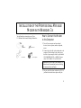
WELCOME TO 56K* INFORMATION ACCESS
The International Telecommunication Union (ITU)
decides the technical protocols that communications
devices must use to operate with each other.
Modems that comply with ITU standards can “talk”
to other standards-compliant modems and fax
machines worldwide.
The ITU has determined a worldwide standard for
56K modem technology, V.90. With a 3Com
U.S. Robotics modem, you can get 56K Internet
access from any service provider who offers the ITU
V.90 standard or 3Com 56K technology. 3Com is
working with providers everywhere to quickly
upgrade their service to the ITU V.90 standard.
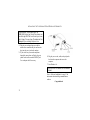
∗ In accordance with the ITU standard for V.90
transmissions and 3Com 56k x2 technology, this
modem is capable of 56 Kbps downloads. However,
the download speeds you experience may be lower
due to varying line conditions and other factors.
Uploads from users to server equipment travel at
speeds up to 31.2 Kbps. An analogue phone line
compatible with the ITU V.90 standard or 3Com
56K x2 technology, and an Internet provider or
corporate host site with the ITU V.90 standard or
3Com 56K x2 technology are necessary for these
high-speed downloads.
See http:// www.3com.com/56k for details.
1
PRODUCT FEATURES
Modulation Schemes
ITU-T V.90
3Com 56K technology
ITU-T V.34+
ITU-T V.34
ITU-T V.32 bis
ITU-T V.32
ITU-T V.23
ITU-T V.22 bis
ITU-T V.22
Bell 212A
ITU-T V.21
Bell 103
Error Control and Data
Compression Schemes
ITU-T V.42
ITU-T V.42 bis
MNP 2-5
2
Fax Modulation Schemes
ITU-T V.17
ITU-T V.29
ITU-T V.27ter
ITU-T V.21
Fax Standards
EIA 578 Class 1 FAX
EIA 592 Class 2.0 FAX
V.90/x2 Front Channel Link
Rates
28000, 29333, 30666, 32000,
33333, 34666, 36000, 37333,
38666, 40000, 41333, 42666,
44000, 45333, 46666, 48000,
49333, 50666, 52000, 53333,
54666, 56000
V.90/x2 Back Channel Link
Rates
4800, 7200, 9600, 12000,
14400, 16800, 19200, 21600,
24000, 26400, 28800, 31200,
33600
V.34+ Link Rates
4800, 7200, 9600, 12000,
14400, 16800, 19200, 21600,
24000, 26400, 28800, 31200,
33600
V.32 bis Link Rates
4800, 7200, 9600, 12000,
14400
Additional Link Rates
300, 1200/75 (V.23), 1200,
2400
Fax Link Rates
2400, 4800, 7200, 9600, 12000,
14400
PRODUCT FEATURES
Summary of Features
Key Features of the 56K Professional Message
Modem
The 56K Professional Message Modem is the first
product to incorporate a digital answering machine,
built-in speakerphone and external modem into one
design. The 56K Professional Message Modem also
features a bank of flash memory that allows you to
receive fax and voice messages without the
intervention of the PC. Voice messages can be
received even when the PC is not switched on.
Voice messages can be retrieved from a remote
location or locally by using buttons on the top of the
modem.
The 56K Professional Message Modem comes
with specially designed application software.
This product is not just a normal voice/ fax/ data
modem. The software includes all features
needed to manage both the 56K Professional
Message Modem in answering machine mode
and the normal fax and voice message mode.
In order to use the fax feature of the modem, refer
to the instructions for faxing that accompany your
software application.
56K Professional Message Modem
• Offers 3Com’s proprietary 56K technology which
allows download capability up to
56 Kbps.
• Offers features of an answering machine through
the six push buttons on the top of the modem.
• Works as a full-duplex speakerphone even in the
absence of the PC.
• Is a feature-enhanced external modem with
added Flash Memory to store messages when
your PC is off.
• Provides the full functionality of a standard
3Com brand modem.
• Retains incoming fax and voice messages and
therefore is not just a pass through device.
3
PRODUCT FEATURES
• Is capable of receiving and storing incoming fax
and voice messages without any DTE (Data
Terminal Equipment) intervention.
• Allows you to forward your faxes to a predefined
phone number.
• Has Caller ID.
• Can transfer stored messages to the DTE at a
later time.
• Enables remotely stored voice messages to be
accessed through a dial-up connection or by
using the push buttons on the top of the modem.
• Offers a built-in condenser microphone.
• Includes software designed specifically for use
with the 56K Professional Message Modem. The
software allows the user to take full advantage of
all features in the product. Other software can be
used for all standard modem functions. We
recommend using the software delivered with the
product.
4
Flash ROM Upgradable
56k Professional Message Modem supports software
download through flash memory. You can quickly
and easily download the most recent updates and
upgrades.
Personal Voice Mail
The supplied communications software enables
business-quality voice messaging system with single
or multiple mailboxes for use in the home or office.
You can customise voice message greetings like a
standard answering machine, and even access your
fax and voice messages remotely.
Your modem will auto-detect incoming fax, voice,
and data calls and switch functions accordingly. Up
to one hundred documents can be pre-configured for
distribution via the Fax on Demand facility.
PRODUCT FEATURES
Answering Machine Features
Before You Begin
Your new Professional Message Modem is set up
from the factory as an answering machine with the
fax capability disabled. In order to use the fax
features, a PC is necessary to adjust default settings.
Also, you will need to set a password, using a PC,
for use with the remote feature of the modem. Refer
to the software package to choose your 4-digit
password.
It is also necessary to record a Personal Greeting
Message and Secondary Message to use with the
Professional Message Modem. The following
section provides full instructions of how to achieve
this.
2) From the modem buttons, and
3) Remotely.
You may use either the internal microphone (handsfree mode) or the connected handset (handset mode)
from both the software application and the modem
buttons. If you wish to record your Personal
Greeting Message remotely, you must use the
handset of a remote touch tone phone.
1) Recording your personal greeting
message using the software application
Hands-free mode
1. Within the Independent Mode Greeting Screen,
click Record, and recite your personal greeting
message.
Personal Greeting Message
Your personal greeting message can be recorded in
three ways using the Professional Message Modem
(PMM):
1) From the software application,
5
PRODUCT FEATURES
If the recording limit of 15 seconds is reached,
the recording will stop and a dialogue window
will display a warning message.
If the recording limit of 15 seconds is reached,
the recording will stop and a dialogue window
will display a warning message.
2. Click Stop when you have finished.
4. Click Stop when you have finished.
3. To listen to your message, press Play from the
supplied software application.
4. Once you have recorded your personal greeting
message, click Download to send your personal
greeting message to the modem.
5. To listen to your message, press the Play button
from within the application software.
6. Once you have recorded your personal greeting
message, click Download to send your personal
message to the modem.
5. If you pick up the handset before clicking Stop,
the message will not be recorded. You cannot
switch back and forth between the handset mode
and the hands-free mode during the recording
process.
Make sure you have completed your personal
message before hanging up the handset or clicking
Stop, otherwise your message will not be recorded.
Once you have started recording your message with
the handset, you cannot switch to hands-free mode.
Handset mode
1. Select Handset as the Input device from within
the Independent Mode Greeting screen.
2. Pick up your handset before clicking Record in
the software application.
3. Click Record, and recite your personal greeting.
6
2) Recording your personal greeting
message using the modem buttons
Hands-free mode
1. Press REC/>>
>>, hold for 2 SECONDS, listen for
the tone, release the button, and recite your
message.
PRODUCT FEATURES
2. Press STOP/PLAY when you have finished
your personal message.
3. Your message will automatically play back after
a tone.
A tone will sound if the recording limit is
reached.
Handset mode
1. Pick up your handset before pressing REC/>>
>>.
2. Press REC/>>
>>, hold for 2 SECONDS, listen for
the tone, release the button, and recite your
message.
3. Press STOP/PLAY when you have finished
your personal message.
4. Your message will automatically play back after
a tone.
A tone will sound if the recording limit is
reached.
If you hang up the handset during the recording
session, your message will not be recorded.
3) Recording your personal greeting
message remotely
1. Pick up the handset of your touch tone telephone
and dial the number of the phone line to which
your modem is connected.
2. Enter your 4-digit password using the keypad on
your touch tone phone.
3. Press 7, listen for the tone, and recite your
message.
4. Press 0 when you have finished.
5. Your message will automatically play back after
a tone.
A tone will sound if the recording limit is
reached.
If you hang up during the recording session, your
message will not be recorded. You will have three
chances to enter the correct password. A tone will
sound when you have incorrectly entered your
password. After the third incorrect attempt, your
modem automatically disconnects.
7
PRODUCT FEATURES
Secondary Message
You can record a second message, which will be
played instead of your personal greeting message,
when your message box is full. This additional
message is recorded using the supplied software
application.
You may use either the internal microphone (handsfree mode) or the connected handset (handset mode
from the application software).
Hands-free mode
1. Within the Independent Mode Message Full
Screen, click Record, and recite your secondary
message.
If the recording limit of 15 seconds is reached,
the recording will stop and a dialogue window
will display a warning message.
4. Once you have recorded your secondary
message, click Download to send your
secondary message to the modem.
5. If you pick up the handset before clicking Stop,
the message will not be recorded. You cannot
switch back and forth between the handset mode
and the hands-free mode during the recording
process.
Handset mode
1. Select Handset as the Input device from within
the Independent Mode Message Full Screen.
2. Pick up your handset before clicking Record in
the software application.
3. Click Record, and recite your secondary
message.
2. Click Stop when you have finished.
If the recording limit of 15 seconds is reached,
the recording will stop and a dialogue window
will display a warning message.
3. To listen to your message, press Play from the
supplied software application.
4. Click Stop when you have finished.
8
PRODUCT FEATURES
5. To listen to your message, press the Play button
from within the application software.
6. Once you have recorded your secondary
message, click Download to send your
secondary message to the modem.
7. Make sure you have completed your entire
message before hanging up the handset or
clicking Stop, otherwise your message will not
be recorded. Once you have started recording
your message with the handset, you cannot
switch to hands-free mode.
Voice Message Retrieval
Voice messages can be retrieved in three ways:
1) From the software application,
2) From the modem buttons, and
3) Remotely.
Messages will be stored on the PC only when
retrieving them through the software application.
Messages can be transferred from the modem’s
memory to your PC using your software application.
Messages can be played back through either the
internal speaker (hands-free mode) or the connected
handset (handset mode) from the software
application and the modem buttons. Remotely,
recorded messages can be played back using the
handset of a remote touch-tone telephone.
The number of voice messages is indicated by a tone
for each new voice message. For example, if you
have 4 new messages, you will hear 4 tones.
Fax messages will not be indicated by a tone.
1) Retrieving voice messages using the
software application
Hands-free mode
1. Select Microphone and Modem Speaker as the
respective Input & Output devices from within
the supplied application software.
9
PRODUCT FEATURES
2. Click Play to play back your message through
the internal speaker.
3. Click Stop to end message playback.
4. Playback stops automatically at the end of the
message.
Handset mode
1. Select Handset as the Input & Output device
from within the supplied application software.
2. Pick up your handset before clicking Play.
3. Click Play to playback your message.
4. Hang up the handset to stop the play back of
your message.
2) Retrieving voice messages using the
modem buttons
Hands-free mode
1. Press STOP/PLAY to playback your stored
message(s).
10
2. Stop message playback by pressing
STOP/PLAY again.
Playback stops automatically at the end of the
message(s).
Handset mode
1. Pick up your hand set before clicking
STOP/PLAY.
2. Click STOP/PLAY to play back your
message(s).
3. Hang up the handset to stop the play back of
your message(s).
If you want to switch to hands-free, press SPKR on
the modem before you hang up the handset and
continue playing the message(s).
Playback stops automatically at the end of the
message(s).
Playback ends by hanging up the handset. In the
hands-free and handset modes, press REC/>>
>> to
skip to the next message and press DEL/<<
<< to
repeat the current message. Use Volume up (∆
∆ ) and
PRODUCT FEATURES
Volume down (∇
∇ ) to adjust the volume in the
hands-free and handset modes.
3) Retrieving voice messages remotely
OPTION
9
ACTION
Repeat the new message count.
1
Playback all new messages.
1. Pick up the handset of your touch tone telephone
and dial the number of the phone line to which
your modem is connected.
2
Playback all stored messages,
new and old.
3
Skip to next voice message.
2. Enter your 4-digit password after the tone.
6
Repeats current voice message.
3. If the password is correct, the number of new
messages will be indicated by that number of
tones.
0
Stop message playback and
continue with any of the options.
Hang up the handset to
end remote operation.
*
Your PMM automatically hangs up after 15
seconds, if no buttons are pressed.
11
PRODUCT FEATURES
Deleting Messages
The Professional Message Modem memory has
limited space to store messages. If this limit is
reached during the reception of a message, the
message is cut off and flagged. No new messages
will be stored until the old messages are erased.
You can free up memory space in three ways:
1. Load the supplied application software to
retrieve and erase all the voice and/ or fax
messages in memory,
2. Press DEL/<<
<< on the modem buttons for 2
SECONDS, and
3. Remotely by pressing 44 on your touch tone
phone.
In the last two options, deletion is denied if the
memory has any new messages that have not been
retrieved. If you are trying to delete your messages
and you still have new voice messages and/or
new/old fax messages, this request will be denied.
12
Only if ALL of your old voice messages are checked
and there are no new fax messages in memory will
you be able to delete your messages and free up
memory in your modem.
The delete function erases all messages in
memory. You cannot delete select messages.
Speakerphone Features
The Professional Message Modem works as a
speakerphone. You can receive incoming calls by
pressing SPKR. You may use the connected
handset to dial out. You can switch between handset
and speakerphone any time using SPKR. If the
handset is hung up before pressing SPKR, the call
will be aborted.
The Volume up (∆
∆ ) and Volume down (∇
∇ ) will be
the only buttons working in the speakerphone
mode; STOP/PLAY, REC/>>
>> and DEL/<<
<< will
not work in speakerphone mode.
PRODUCT FEATURES
Facsimile (Fax) Features
Fax Forwarding
Faxes can be forwarded to a predefined phone
number. The faxes will continue to be forwarded
until the feature is disabled. The faxes can be
redirected to a different number at any time by
changing the predefined number through the
software application.
The fax forwarding feature is controlled through the
software application or remotely.
1) Fax forwarding using the software
application
Set the phone number in the application (number is
stored in the flash memory of the modem) and then
enable/disable using the applicable button.
2) Fax forwarding remotely
(remote control is limited only to the enable/
disable feature as follows)
a) Enter your password and from the Main
menu, press Ä to toggle the enable/disable fax
forwarding feature.
Confirmation of the enabling/disabling of this
feature will be indicated by an opening/closing tone.
Facsimile (Fax)
A call answered with the handset or
speakerphone button,
which turns out to be a fax, will not be lost, if
you press the STOP/PLAY button for 2
SECONDS.
Independent Mode Facsimile (Fax)
Forwarding
Faxes can be forwarded to a predefined
phone number. The faxes will continue to be
forwarded until the feature is disabled. The
faxes can be redirected to a different number
13
PRODUCT FEATURES
at any time by changing the predefined
number through the software application.
The Independent mode fax forwarding
feature is controlled through the software
application or remotely.
A call answered with the handset or speakerphone
button, which turns out to be a fax, will not be
aborted, if you press the STOP/PLAY button for
2 SECONDS. This allows the modem to
automatically receive the incoming fax.
1) Setup Independent Fax mode
Set the phone number in the application
(number is stored in the flash memory of
the modem) and then enable/disable
using the applicable button.
2) Fax forwarding dial up control
(remote control is limited only to the
enable/disable feature as follows)
a)
Enter your password and from the
Main menu, press Ä to toggle the
enable/disable fax forwarding feature.
b)
Confirmation of the
enabling/disabling of this feature will be
indicated by playing an opening/closing
tone.
Caller ID Feature
Manual Reception of a Fax Call
14
The Caller ID feature discloses the identification of
the caller prior to answering the call. You can
enable/disable this feature through the software
application, where a window is provided to reveal
the caller. (Caller ID service may have to be
purchased separately from your telephone
company.)
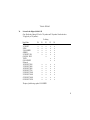
Toll Saver Feature
The Professional Message Modem is generally set to
answer after a certain number of rings (usually 3 to
6). With the toll saver feature enabled, the modem
will detect new voice messages in memory and
answer with 2 rings less than the preset number of
rings. If there are no new messages or the toll saver
feature is disabled, the modem will answer after the
preset number of rings.
PRODUCT FEATURES
Number of
Preset Rings
Number of rings with
toll saver enabled or
with new voice
messages
3*
2
4
2
5
3
6
4
*PTT requirement of certain countries requires that
the modem answer after 2 rings.
Modem Push Buttons
SPKR
Speakerphone
1) Switch between hands-free and handset modes
during playback
2) Answer incoming calls as a speakerphone
3) Switch between speakerphone and handset
modes
STOP/PLAY
Stop/Play
1) Stop and start the playback of voice messages
2) Stop recording your personal message
3) Stop playback of your personal message
4) Initiate fax session—see Aborted Fax Call
15
PRODUCT FEATURES
DEL/<<
<<
Delete/Repeat
Front Panel Lights
1) Erase messages,
The PMM has five LEDs—two of which are bicolor
(red/green).
2) Repeats the current message.
REC/>>
>>
Record/Fast Forward
1) Record your personal message,
2) Skip to the next message.
PWR/MEM (Bicolor LED)
Power/Message Memory
1) Constant red indicates that auto answer is off
and the modem will not answer any calls when
the PC is off.
∆ and ∇
Volume up/Volume down
2) Constant green indicates that auto answer is on
and your modem is ready to accept messages
when the PC is off.
1) Control the volume during personal message
playback in hands-free mode,
3) Rapid green and rapid red flashes indicate that
the message memory is full.
2) Control the volume during message playback in
hands-free mode, and
MSG (Bicolor LED)
Message
3) Control the volume of the speakerphone.
1) Blinks red once for each new fax message
2) Blinks green once for each new voice message.
16
PRODUCT FEATURES
3) Solid amber indicates that you have retrieved
your messages, but that they have not been
deleted from memory.
RD
Received Data
Flickers red when the modem is receiving data.
SD
Send Data
Flickers red when the modem is sending data.
OH
Off Hook
Constant red when the modem is off-hook.
17
PRODUCT FEATURES
Telephone Handset DTMF Digits for Remote Message Retrieval
Digit(s) Function
1
2
3
44
5
6
7
8
9
0
*
#
18
Starts playback of all new voice messages
Starts playback of all stored voice messages (new and old)
Skips to the next voice message
Deletes all old voice messages in memory
Enables/disables fax forwarding feature
Repeats the current voice message
Records personal message
Not used
Repeats the new message count
1) Stops playback of all voice messages
2) Stops the recording of your personal message
3) Stops playback of your personal message
Hangs up the modem
Not used
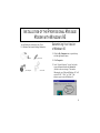
INSTALLATION OF THE PROFESSIONAL MESSAGE
MODEM WITH WINDOWS 95
You will need these items from your 3Com
U.S. Robotics Professional Message Modem box:
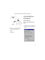
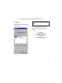
Determining Your Version
of Windows 95
1. Click the My Computer icon on your desktop
with the right mouse button.
modem
power adaptor
phone lead
serial cable
2. Click Properties.
3. In the “System Properties” screen, look at the
system information under the General tab
(circled in the screen image). The number
following the text “Microsoft Windows 95” will
end with “950,” “950a,” or “950b.” This
indicates your version of Windows 95.
19
INSTALLATION OF THE PROFESSIONAL MESSAGE MODEM WITH WINDOWS 95
Write down your version of Windows.
Windows 95 version __________
Click OK.
How to Connect the Modem
to the Computer
1. Turn off your computer and any attached
devices, such as a printer, monitor, keyboard,
and mouse.
2. Connect the serial cable to the modem and to the
computer. When looking for your serial port on
the back of your computer, look for ports labeled
COM, MODEM, RS-232, or SERIAL. Do not
select AUX, GAME, LPT, or PARALLEL.
Remember which serial port you selected. This
information will be necessary when installing
your communications software.
3. Plug one end of the phone cord into the TELCO
jack and the other end into a phone wall jack.
20
The phone jack you use must be for an
ANALOGUE phone line. Most office phones are
wired through DIGITAL lines. Be sure you know
which type of line you have. The modem will be
damaged if you use a digital phone line.
4. Plug the power adaptor that came with the
modem into a standard wall jack and insert its
plug into the power jack on the modem.
5. If you wish to use your modem and phone
through the same phone wall jack, plug your
phone's cord into the modem's PHONE jack.
Use an adaptor cable if necessary.
INSTALLATION OF THE PROFESSIONAL MESSAGE MODEM WITH WINDOWS 95
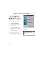
Installing Modem Drivers
with Windows 95:
Versions 950 and 950a
Moving Through the “New Hardware Found”
Screens
6. Plug the power cords, cables, and peripherals
back into the computer and turn on the
computer.
1. When Windows 95 restarts, it should detect the
modem. If it does, you will see the following
screen.
7. Start Windows 95.
21
INSTALLATION OF THE PROFESSIONAL MESSAGE MODEM WITH WINDOWS 95
Click Driver from disk provided by hardware
manufacturer. Then click OK.
If this screen does not appear, refer to “If Plug
and Play Does Not Detect Your Modem” on
page 45.
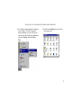
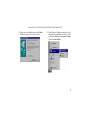
2. When you see the Install from Disk screen,
• If you have a disk that contains your
modem’s drivers, insert the disk into your
disk drive, usually A.
• If you have a CD-ROM that contains your
modem’s drivers, insert the CD-ROM into
your CD-ROM drive, usually D.
If your disk drive or CD-ROM drive is a
different letter, type that letter instead of A or D.
22
Click OK. Windows will install the drivers for
your new modem.
INSTALLATION OF THE PROFESSIONAL MESSAGE MODEM WITH WINDOWS 95
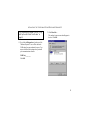
3. Once Windows finishes loading the information
from your disk or CD-ROM, verify that the
modem installation was a success. When your
desktop returns, click the Windows Start button
and point to Settings. Then click Control
Panel.
4. Double-click the Modems icon (circled in the
screen image below).
23
INSTALLATION OF THE PROFESSIONAL MESSAGE MODEM WITH WINDOWS 95
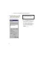
5. In the “Modems Properties” screen, you should
see 56K Professional Message Modem listed.
This indicates that your new Professional
Message Modem is installed correctly.
If this screen does not appear, refer to “If Plug
and Play Does Not Detect Your Modem” on
page 45.
6. Next, click the Diagnostics tab at the top of the
“Modems Properties” screen. Write down the
COM setting for your modem in the space
below. You may need to know this setting when
you install your communications software.
COM Port___________
24
INSTALLATION OF THE PROFESSIONAL MESSAGE MODEM WITH WINDOWS 95
7. Click More Info….
The modem’s status screens should appear in
the box. Click OK.
Be sure to install software after the modem is
installed.
Turn to “Software Installation” on page 34 for
information about installing communications
software.
Congratulations!
You are ready to start using your
3Com U.S. Robotics
Professional Message Modem
25
INSTALLATION OF THE PROFESSIONAL MESSAGE MODEM WITH WINDOWS 95
Installing Modem Drivers
with Windows 95: Version 950b
Using the Update Device Driver Wizard Screens
1. When you see the following screen,
• If you have a disk that contains your
modem’s drivers, insert the disk into your
disk drive, usually A.
• If you have a CD-ROM that contains your
modem’s drivers, insert the CD-ROM into
your CD-ROM drive, usually D.
If your disk drive or CD-ROM drive is a
different letter, type that letter instead of A or D.
26
Click Next.
If this screen does not appear, refer to “If Plug
and Play Does Not Detect Your Modem” on
page 45.
INSTALLATION OF THE PROFESSIONAL MESSAGE MODEM WITH WINDOWS 95
2. When you see the following screen, click Finish.
Windows will copy files to your hard drive.
3. When Windows is finished copying files, verify
that the modem installation was a success. Click
the Windows Start button and point to Settings.
Then click Control Panel.
27
INSTALLATION OF THE PROFESSIONAL MESSAGE MODEM WITH WINDOWS 95
4. Double-click the Modems icon (circled in the
screen image below).
28
5. In the “Modems Properties” screen, you should
see 56K Professional Message Modem listed.
This means that your modem is installed
correctly.
INSTALLATION OF THE PROFESSIONAL MESSAGE MODEM WITH WINDOWS 95
If this screen does not appear, refer to “If Plug
and Play Does Not Detect Your Modem” on
page 45.
7. Click More Info….
The modem’s status screens should appear in
the box. Click OK.
6. Next, click the Diagnostics tab at the top of the
“Modems Properties” screen. Write down the
COM setting for your modem in the space. You
may need to know this setting when you install
your communications software.
COM Port_________
Click OK.
29
INSTALLATION OF THE PROFESSIONAL MESSAGE MODEM WITH WINDOWS 95
Be sure to install software after the modem is
installed.
Turn to “Software Installation” on page 34 for
information about installing communications
software.
Congratulations!
You are ready to start using your
3Com U.S. Robotics
Professional Message Modem
30
INSTALLATION OF THE PROFESSIONAL MESSAGE
MODEM WITH WINDOWS 3.X
You will need these items from your 3Com
U.S. Robotics Professional Message Modem box:
modem
serial cable
phone lead
power adaptor
How to Connect the Modem
to the Computer
1. Turn off your computer and any attached
devices, such as a printer, monitor, keyboard,
mouse.
2. Connect the serial cable to the modem and to the
computer. When looking for the serial port on
the back of your computer, look for ports labeled
COM, MODEM, RS-232, or SERIAL. Do not
select AUX, GAME, LPT, or PARALLEL.
Remember which serial port you selected. This
information will be necessary when installing
your communications software.
3. Plug one end of the phone cord into the TELCO
jack and the other end into a phone wall jack
31
INSTALLATION OF THE PROFESSIONAL MESSAGE MODEM WITH WINDOWS 3. X
The phone jack you use must be for an
ANALOGUE phone line. Most office phones are
wired through DIGITAL lines. Be sure you know
which type of line you have. The modem will be
damaged if you use a digital phone line.
4. Plug the power adaptor that came with the
modem into a standard wall jack and insert its
plug into the power jack on the modem.
5. If you wish to use your modem and phone
through the same phone wall jack, plug your
phone's cord into the modem's PHONE jack.
Use an adaptor cable if necessary.
6. Plug the power cords, cables, and peripherals
back into the computer and turn on the
computer.
7. Start Windows 3.x.
Be sure to install software after the modem is
installed.
Turn to “Software Installation” on page 33 for
information about installing communications
software.
Congratulations!
32
INSTALLATION OF THE PROFESSIONAL MESSAGE MODEM WITH WINDOWS 3. X
You are ready to start using your
3Com U.S. Robotics
Professional Message Modem
33
SOFTWARE INSTALLATION
Voice Fax, and Data Software (communications
software) allows you to send and receive faxes
directly from your computer desktop. You can build
your own fax directory, send faxes to specified
groups of fax numbers, select individual cover pages
when necessary, and send individual faxes without
exiting your word processing program.
Communications software allows you to change
settings and issue commands to your modem.
Additionally, voice communications software lets
you connect to Bulletin Board Systems (BBS) and
other online data providers. Take advantage of this
access to enter a new world of information and
entertainment.
3. In the Run dialog box, type A:\setup.exe or
D:\setup.exe and press ENTER. If your disk
drive or CD-ROM drive is a different letter, type
that letter instead of A or D.
4. Then click OK.
5. Follow the on-screen instructions to install your
Voice Fax, Data, and Telecommunications
Software.
Windows 3.x
1. Insert the communications software disk or CDROM into your disk drive or CD-ROM drive.
2. In Program Manager, click File and select Run.
Windows 95
1. Insert the communications software disk or CDROM into your disk drive or CD-ROM drive.
3. In the text box, type A:\setup.exe or
D:\setup.exe and press ENTER.
If your disk drive or CD-ROM drive is a
different letter, type that letter instead of A or D.
2. Go to the Windows Start menu and select Run.
4. Then click OK.
5. Follow the on-screen instructions to install your
Voice Fax, Data, and Telecommunications
Software.
34
S OFTWARE INSTALLATION
Refer to your software manual for the specific
installation instructions. The software’s installation
program will ask you questions about the modem
you are using. You may need the following
information when installing a communications
software package.
Type of Modem
Most communications software programs will ask
you to select the type of modem you are using.
Select a 3Com U.S. Robotics high speed modem. If
that selection is not listed, pick Courier Dual
Standard, V.32 bis, or V.34.
Initialisation String
For hardware flow control, a fixed serial port rate,
and full result codes and the PMM answer machine
feature disabled (PWR/MEM LED = red), type:
AT&F1+MCA=0 and then press ENTER.
If you must use software flow control, type:
AT&F2+MCA=0 and then press ENTER.
Flow Control
•
•
For hardware flow control (highly
recommended), select RTS/CTS.
For software flow control, select XON/XOFF.
Disable the type of flow control (hardware or
software) that you are not using.
Upon exit of the non-supplied software,
execute the supplied application software to
re-initialise all the answer machine
functionality if required.
UART - Universal Asynchronous
Receiver Transmitter (External Modems
Only)
If you are running Windows 3.x or you have
upgraded your system from Windows 3.x to
Windows 95, you can run MSD to determine your
UART setting. In DOS, type MSD at the Windows
directory and then press ENTER.
35
S OFTWARE INSTALLATION
Follow the on-screen instructions to access the
COM port settings panel. In this panel you should
find the UART chip used. Match the UART type
listed in MSD with the serial rate listed in the chart.
Select this serial rate in any fax/data programs you
use.
If this is your UART...
Select this serial rate
16550
16450
8250
115.2 or 57.6 Kbps
38.4 Kbps
19.2 Kbps
Do not select a 28,800, 14,400, or 12,000 bps
serial port rate if offered. Your modem will not
work correctly with any of these settings. Fix
or lock the serial port (baud) rate. If it’s
referred to as autobaud, select OFF.
Congratulations!
You are now ready to start using your
36
3Com U.S. Robotics
Professional Message Modem
U.S. ROBOTICS MODEM UPDATE WIZARD
Your CD-ROM includes the U.S. Robotics Modem
Update Wizard. This software is designed to quickly
update your modem to a newer version of its current
code
You can also obtain this software from our World
Wide Web page http://www.3com.com.au
Complete the instructions in the “Software
Installation" section on page 34 of this manual
before installing the Modem Update Wizard.
Installation
1. Insert the CD into your CD-ROM drive.
2. Click the Windows Start menu and point to
Programs. Point to Connections CD. Then
click Connections CD.
3. From the main Connections CD menu, click the
Customer Support button.
4. Click the Modem Update Wizard button.
5. Follow the on-screen instructions to complete
the installation.
6. This screen indicates that the setup is complete.
Click OK
37
U.S. R OBOTICS MODEM U PDATE WIZARD
Updating
1. Click the Windows Start button. Point to
Programs. Then point to U.S. Robotics Modem
Update Wizard and click the Modem Update
Wizard selection. (Note: The number that the
software dials to connect to the Modem Update
Wizard may not be free of charge.)
2. Follow the on-screen instructions to complete
the update process.
WARNING! To avoid the risk of damaging
your modem, do not turn off the modem while it is
being updated.
Congratulations!
Enjoy the benefits of your updated
3ComU.S. Robotics
Professional Message Modem!
38
TROUBLESHOOTING
Read This First!
1. Click Windows Start, point to Settings, and click Control Panel.
2. Double-click the Modems icon.
3. Click the Diagnostics tab.
4. Click the COM port that your modem is assigned to, so that it is highlighted. If you do not see your modem
on this screen, you need to shut down the computer and uninstall the modem. Exit out of the Modems
Properties screen by clicking Cancel. Click Start, Shut Down, select the Shut down the computer? option,
and then click Yes. When your computer has shut down, turn it off and unplug it from its power outlet.
Unplug its serial cable from the computer’s COM port. Reinstall your modem following the directions in the
“External Modem Installation with Windows 95” chapter, but use a different COM port.
5. Highlight your modem and click More Info. You should see a list of the modem’s ATI commands. Click OK
and exit out of all open screens. If the ATI commands do not appear, your modem is not properly installed.
Reinstall your modem following the directions in the “Installation of the Professional Message Modem with
Windows 95” chapter on page 19.
39
TROUBLESHOOTING
PROBLEM
The computer or software will not recognise the modem.
POSSIBLE SOLUTION
Make sure the modem is plugged in and turned on. Use only the power adaptor included with your modem.
POSSIBLE SOLUTION
You may not be entering modem commands in the proper manner. Type in all upper case (AT) or all lower case
(at).
POSSIBLE SOLUTION
The COM port may not be enabled. Refer to your computer’s manual for information about enabling COM ports
(usually involves altering the bios settings, motherboard jumpers, and the operating system).
POSSIBLE SOLUTION
You may be using the wrong serial cable with your external faxmodem. Make sure you are using an RS-232
modem cable. You will need to make sure you are using a 25-pin male to 25-pin female if your COM port is a
25-pin port, or a 25-pin male to 9-pin female if your COM port is a 9-pin port.
40
TROUBLESHOOTING
PROBLEM
The modem will not go off hook to dial or does not answer the phone.
POSSIBLE SOLUTION
You may have plugged your modem’s phone cord into a digital line. Plugging your modem’s phone cord into a
digital phone line can damage the modem. Call your phone company if you are unsure whether or not your phone
line is digital.
POSSIBLE SOLUTION
You may have plugged your modem’s phone cord into the wrong jack on the modem. Make sure the phone cord
is plugged into a jack labeled with .
POSSIBLE SOLUTION
You might have a bad phone cord connection to your modem. The phone cord should be plugged into the jack
labeled
on the modem and the wall phone jack. The phone cord should be no longer than 12 feet in length.
Use the phone cord included with your modem if possible.
POSSIBLE SOLUTION
You may have devices between the modem and the phone jack. There should be no line splitters, fax machines,
or other devices between the modem and the wall jack.
POSSIBLE SOLUTION
Your software may not have auto answer enabled. Enable the auto answer feature. In your communication
software’s terminal mode, type ATS0=1 and press ENTER. You need to enable auto answer before every session
unless you alter your software’s initialisation string to permanently enable auto answer.
41
TROUBLESHOOTING
POSSIBLE SOLUTION
You may be using the wrong power adaptor for your modem. Use only the power adaptor that came with your
modem.
PROBLEM
Both modems sound like they are exchange carrier signals, but fail to establish a connection.
POSSIBLE SOLUTION
You may have a poor line connection. Place the call again. Calls are routed differently each time.
PROBLEM
Your 56K modem cannot achieve a 56K Internet connection.
POSSIBLE SOLUTION
Your modem is capable of receiving data at speeds up to 56 Kbps and sending data at speeds up to 31.2 Kbps.
However, the download speeds you experience may be lower due to varying line conditions. An analogue phone
line compatible with ITU-T V.90 or 3Com 56K technology, and an Internet provider or corporate host site
compatible with ITU-T V.90 or 3Com 56K technology are necessary for these high-speed downloads. Check
http://www.3com.com/56k for a list of ISPs that observe ITU-T V.90 and/or offer 3Com 56K technology.
POSSIBLE SOLUTION
The phone lines in your area may not be 56K compatible. Call your phone company to find out if your phone line
is compatible with ITU-T V.90 and/or is compatible with 3Com 56K technology.
42
TROUBLESHOOTING
POSSIBLE SOLUTION
You may have devices between the modem and the phone jack. There should be no line splitters, fax machines,
or other devices between the modem and the wall jack.
PROBLEM
Errors are constantly occurring in your V.17 fax transmissions.
POSSIBLE SOLUTION
Your modem initialisation string may be insufficient for fax transmissions. In terminal mode, type the following
initialisation string: AT&F&H3&I2&R2S7=90 then press ENTER.
POSSIBLE SOLUTION
There may be a Terminate and Stay Resident (TSR) program (such as a screen saver or virus scanner) running in
the background, disrupting data communications. Disable any Terminate and Stay Resident (TSR) programs
running in the background. If you have software running as a TSR, check the software’s manual for information
about disabling its ability to operate as a TSR.
POSSIBLE SOLUTION
Your baud rate may be set too high. In your communications software, lower the baud rate to 9600, 7200, or
4800.
POSSIBLE SOLUTION
You may be trying to fax a compressed file. Decompress the file using the application with which it was
compressed. Then open it in the application with which it was created. Select your fax software as the printer and
then print the file.
43
TROUBLESHOOTING
PROBLEM
Your communications software fails to initialise the modem.
POSSIBLE SOLUTION
Your software’s port settings may be incorrect. Make sure the software’s port settings match those for your
modem.
POSSIBLE SOLUTION
Make sure the modem is plugged in and turned on. Use only the power adaptor included with the modem.
POSSIBLE SOLUTION
(External modems only) Make sure that you are using an RS-232 modem cable.
44
TROUBLESHOOTING
PROBLEM
If Plug and Play (PNP) does not detect your modem. You have installed the modem and Windows has
restarted, but you see only your normal desktop. You do not see any screens indicating new hardware
has been detected.
POSSIBLE SOLUTION
The Plug and Play installation was not successful. Try the following:
1. Click Start and click Shut Down.
2. When asked if you wish to shut down your computer, click Yes.
3. When Windows indicates that it is safe to turn off your computer, turn it off.
4. Wait 15 seconds before turning the computer back on.
5. Windows may detect your modem upon this restart, even if it did not detect the modem during the initial
installation.
• If you see screens indicating that new hardware has been detected by Windows, follow the on-screen
instructions to install the modem.
• If you do not see the new hardware screens, continue with step 6.
6. Click Windows Start
7. Point to Settings
45
TROUBLESHOOTING
8. Click Control Panel.
9. Double-click the System icon.
10.Click the Device Manager tab on the “System Properties” screen.
11. Look for “Other Devices” or “Unknown Devices” in the list that appears.
• If you do not see either of these options in the list, contact customer support for technical assistance.
• If you do see one of these options, double-click the option and continue with step 12.
12. If the description that appears matches the modem you are trying to install, click Remove. If it does not,
contact customer support for technical assistance.
13. Click OK when Windows asks if you wish to remove the device.
14.Restart the computer and continue with the on-screen instructions. If the computer does not detect the modem
after this second restart, contact customer support for technical assistance.
46
GLOSSARY
Cross references are printed in boldface. Cross
references with items in the Data Commands found
in the “Technical Reference” section, are printed in
italics.
application
A computer program designed to perform a specific
function, such as a word processing or organizing
data into a spreadsheet.
analogue loopback
A modem self-test in which data from the keyboard
or an internal test pattern is sent to the modem's
transmitter, turned into analog form, looped back to
the receiver, and converted back into digital form.
ARQ
Automatic Repeat reQuest is a general term for a
function that automatically allows your modem to
detect flawed data and retransmit it. See MNP and
V.42.
analog signals
A variety of signals and wavelengths that can be
transmitted over communications lines such as the
sound of a voice over the phone line. These signals
are in contrast with digital signals.
ASCII
American Standard Code for Information
Interchange is a code used to represent letters,
numbers, and special characters, such as $, !, and
/.
answer mode
The mode used by your modem when answering an
incoming call from an originating modem. The
transmit/receive frequencies are the reverse of the
originating modem, which is in originate mode.
47
GLOSSARY
asynchronous transmission
Data transmission in which the length of time
between transmitted characters may vary. Since the
time lapses between transmitted characters are not
uniform, the receiving modem must be signaled as
to when the data bits of a character begin and then
they end. The addition of start/stop bits to each
character serves this purpose.
auto answer
In this setting the modem can pick up the phone
line when it detects a certain number of rings. See
S-register S0 in the “Technical Reference” section.
autodial
A process where your modem dials a call for you.
The dialing process is initiated by sending an ATDT
(dial tone) or ATDP (dial pulse) command followed
by the telephone number to dial. Autodial is used to
dial voice numbers. See command Dn.
baud rate
A term used to measure the speed of an analog
transmission from one point to another. Although
not technically accurate, baud rate is commonly
used to mean bit rate.
binary digit
A 0 or 1, which reflects the use of the binary
numbering system. It is used because the computer
recognizes either of two states, OFF or ON. The
shortened form of binary digit is bit.
bit rate
This refers to the number of binary digits, or bits,
transmitted per second (bps). It is also referred to as
transmission rate. Communications channels using
telephone channel modems are established at set bit
rates, commonly 2400, 4800, 9600, 14,400, 28,800
and higher.
bits per second (bps)
This is the bits (binary digits) per second rate.
Thousands of bits per second are expressed as
kilobits per second or kbps.
48
GLOSSARY
buffer
A memory area set aside to be used as temporary
storage during input and output operations. An
example is the modem's command buffer.
byte
A group of binary digits stored and operated upon
as a unit. In user documentation, the term usually
refers to 8-bit units or characters. One kilobyte
(KB) is equal to 1,024 bytes or characters; 640 KB
indicates 655,360 bytes or characters.
carrier
A tone signifying a connection the modem can alter
to communicate data across telephone lines.
characters per second (CPS)
A data transfer rate generally estimated from the bit
rate and the character length. For example, at
2400 bps, 8-bit characters with start/stop bits (for a
total of ten bits per character) will be transmitted at
a rate of approximately 240 characters per second
(cps). Some protocols, such as error-control
protocols, employ advanced techniques such as
longer transmission frames and data compression
to increase cps.
class 1 and 2.0
International standards used between fax
application programs and faxmodems for sending
and receiving faxes.
character
A representation, coded in binary digits, of a letter,
number, or other symbol.
49
GLOSSARY
cyclic redundancy checking (CRC)
An error-detection technique consisting of a test
performed on each block, or frame, of data by both
sending and receiving modems. The sending
modem inserts the results of its tests in each data
block in the form of a CRC code. The receiving
modem compares its results with the received CRC
code and responds with either a positive or negative
acknowledgment.
data communications
A type of communications in which computers are
able to exchange data over an electronic medium.
data compression table
A table containing values assigned for each
character during a call under MNP5 data
compression. Default values in the table are
continually altered and built during each call: The
longer the table, the more efficient throughput
gained.
50
data mode
The mode in which the faxmodem is capable of
sending and receiving data files. A standard modem
without fax capabilities is always in data mode.
DCE
Data Communications Equipment (or CircuitTerminating Equipment) is equipment such as dialup modems that establish and control the data link
via the telephone network.
default
Any setting assumed, at startup or reset, by the
computer's software and attached devices. The
computer or software will use these settings until
changed by the user or other software.
detect phase
In the ITU-T V.42 error-control protocol, the first
stage in establishing if both modems attempting to
connect have V.42 capability.
GLOSSARY
dictionary
The term used for compression codes built by the
V.42 bis data compression algorithm.
digital loopback
A test that checks the modem's RS-232 interface
and the cable that connects the terminal (computer)
and the modem. The modem receives data (in the
form of digital signals) from the computer or
terminal, and immediately returns the data to the
screen for verification.
digital signals
Signals that are discrete and uniform. In this
manual, the term refers to the binary digits 0 and
1. These signals are in contrast with analog signals.
DTE
Data Terminal (or Terminating) Equipment is a
computer that generates or is the final destination of
data.
duplex
Duplex indicates a communications channel capable
of carrying signals in both directions. See half
duplex, full duplex.
Electronic Industries Association (EIA)
This association is a group which defines electronic
standards in the U.S.
error control
A variety of techniques that check the reliability of
characters (parity) or blocks of data. V.42 and
MNP error-control protocols use error detection
(CRC) and retransmission of flawed frames
(ARQ).
facsimile
A method for transmitting the image on a page
from one point to another. This is commonly
referred to as fax.
51
GLOSSARY
fax mode
The mode in which the faxmodem is capable of
sending and receiving files in a facsimile format.
See definitions for V.17, V.27ter, V.29.
flow control
A mechanism that compensates for differences in
the flow of data into and out of a modem or other
device. See commands &Hn, &In, &Rn.
frame
A data communications term for a block of data
with header and trailer information attached. The
added information usually includes a frame number,
block size data, error-check codes, and Start/End
indicators.
full duplex
These signals will flow in both directions at the
same time over one line. In microcomputer
communications, may refer to the suppression of the
online local echo.
52
half duplex
These signals will flow in both directions, but only
one way at a time. In microcomputer
communications, may refer to activation of the
online local echo, which causes the modem to send
a copy of the transmitted data to the screen of the
sending computer.
Hz
Hertz is a frequency measurement unit used
internationally to indicate cycles per second.
ITU-T
An international organization that defines standards
for telegraphic and telephone equipment. For
example, the Bell 212A standard for 1200 bps
communication in North America is observed
internationally as ITU-T V.22. For 2400 bps
communication, most U.S. manufacturers observe
V.22 bis.
GLOSSARY
LAPM
Link Access Procedure for Modems is an errorcontrol protocol defined in ITU-T
Recommendation V.42. Like the MNP protocols,
LAPM uses cyclic redundancy checking (CRC)
and retransmission of corrupted data (ARQ) to
ensure data reliability.
local echo
A modem feature that enables the modem to display
keyboard commands and transmitted data on the
screen. See command En.
MNP
Microcom Networking Protocol is an error-control
protocol developed by Microcom, Inc., and now in
the public domain. There are several different MNP
protocols, but the most commonly used one ensures
error-free transmission through error detection
(CRC) and retransmission of erred frames.
modem
A device that transmits/receives computer data
through a communications channel such as radio or
telephone lines. It also changes signals received
from the phone line back to digital signals before
passing them to the receiving computer.
off/on hook
Modem operations that are the equivalent of
manually lifting a phone receiver (taking it offhook) and replacing it (going on-hook).
online fall back/fall forward
A feature that allows a high-speed, error-control
modem to monitor line quality and fall back to the
next lower speed in a defined range if line quality
diminishes. As line conditions improve, the modem
switches up to the next higher speed.
originate mode
The mode used by your modem when initiating an
outgoing call to a destination modem. The transmit/
receive frequencies are the reverse of the called
modem, which is in answer mode.
53
GLOSSARY
parity
A simple error-detection method that checks the
validity of a transmitted character. Character
checking has been surpassed by more reliable and
efficient forms of error checking, including V.42
and MNP 2-4 protocols. Either the same type of
parity must be used by two communicating
computers, or both may omit parity.
protocol
A system of rules and procedures governing
communications between two or more devices.
Protocols vary, but communicating devices must
follow the same protocol in order to exchange data.
The format of the data, readiness to receive or send,
error detection and error correction are some of
the operations that may be defined in protocols.
RAM
Random Access Memory is memory that is
available for use when the modem is turned on, but
that clears of all information when the power is
turned off. The modem's RAM holds the current
54
operational settings, a flow control buffer, and a
command buffer.
remote digital loopback
A test that checks the phone link and a remote
modem's transmitter and receiver.
remote echo
A copy of the data received by the remote system,
returned to the sending system, and displayed on
the screen. Remote echoing is a function of the
remote system.
ROM
Read Only Memory is permanent memory, which is
not user-programmable.
serial transmission
The consecutive flow of data in a single channel.
Compare it to parallel transmissions where data
flows simultaneously in multiple channels.
GLOSSARY
start/stop bits
These signaling bits are attached to a character
before and after the character is transmitted during
asynchronous transmission.
terminal
A device whose keyboard and display are used for
sending and receiving data over a communications
link. This device differs from a microcomputer or a
mainframe in that it has little or no internal
processing capabilities.
terminal mode
Software mode that allows direct communication
with the modem. This mode is also known as
command mode.
throughput
The amount of actual user data transmitted per
second without the overhead of protocol
information such as start/stop bits or frame
headers and trailers. Compare it with characters
per second.
V.8
The ITU-T standard specification that covers the
initial handshaking process.
V.17 fax
An ITU-T standard for making facsimile
connections at 14,400 bps, 12,000 bps, 9600 bps,
and 7200 bps.
V.21
An ITU-T standard for modems operating in
asynchronous mode at speeds up to 300 bps, fullduplex, on public-switched telephone networks.
V.22
An ITU-T standard for modem communications at
1200 bps, compatible with the Bell 212A standard
observed in the U.S. and Canada.
V.22 bis
An ITU-T standard for modem communications at
2400 bps. The standard includes an automatic link
negotiation fallback to 1200 bps and compatibility
with Bell 212A/V.22 modems.
55
GLOSSARY
V.23
An ITU-T standard for modem communication at
1200 bps with a 75 bps back channel. This standard
is used in the U.K.
V.27ter
An ITU-T standard for facsimile operations that
specifies modulation at 4800 bps, with fallback to
2400 bps.
V.29
An ITU-T standard for facsimile operations that
specifies modulation at 9600 bps, with fallback to
7200 bps.
V.32
An ITU-T standard for modem communications at
9600 bps and 4800 bps. V.32 modems fall back to
4800 bps when line quality is impaired.
56
V.32 bis
An ITU-T standard that extends the V.32
connection range: 4800, 7200, 9600, 12,000, and
14,400 bps. V.32 bis modems fall back to the next
lower speed when line quality is impaired, fall back
further as necessary, and also fall forward (switch
back up) when line conditions improve.
See online fall back/fall forward.
V.34
An ITU-T standard that currently allows data rates
as high as 28,800 bps.
V.34+
An enhancement to V.34 that enables data transfer
rates as high as 33,600 bps.
V.42
An ITU-T standard for modem communications
that defines a two-stage process of detection and
negotiation for LAPM error control.
GLOSSARY
V.42 bis
An extension of ITU-T V.42 that defines a specific
data compression scheme for use during V.42
connections.
V.90
The ITU-T standard for 56 Kbps modem
communications.
Xmodem
The first of a family of error control software
protocols used to transfer files between modems.
These protocols are in the public domain and are
available from many bulletin board services.
Xon/Xoff
Standard ASCII control characters used to tell an
intelligent device to stop/resume transmitting data.
Ymodem
An error-checking protocol that can send several
files of data at a time in 1024-byte (1K) blocks.
This protocol can use either checksums or CRC for
error checking.
Ymodem G
This is similar to the Ymodem, except it relies on
the modem for error checking, which makes it
faster.
Zmodem
This is similar to Xmodem and Ymodem, except it
includes batch transfer, the ability to recover from a
partially complete transfer, an autostart feature, and
improved efficiency.
57
TECHNICAL REFERENCE
Modem Push Buttons
Symbol Meaning
Function
SPKR
Speakerphone
1) Answer incoming calls as a speakerphone
2) Switch between speakerphone and handset modes
3) Switch between hands-free and handset modes during playback
STOP/
PLAY
Stop/Play
1) Start and stop the playback of voice messages
2) Stop recording your personal message
3) Stop playback of your personal message
4) Initiates fax session
DEL/<<
<< Delete/Repeat
1) Erase the messages
2) Repeats the current message
REC/>>
>> Record/
Fast Forward
1) Record your personal message
2) Skip to the next message
∆
∇
58
Volume up/
Volume down
1) Control volume during personal message playback in hands-free mode
2) Control volume during message playback in hands-free mode
3) Control volume of the speakerphone
T ECHNICAL R EFERENCE
Telephone Handset DTMF Digits for Remote Message
Retrieval
Digit(s)
1
2
3
44
5
6
7
8
9
0
*
#
Function
Starts playback of all new voice messages
Starts playback of all stored voice messages (new and old)
Skips to the next voice message
Deletes old voice messages in memory
Enables/disables fax forwarding feature
Repeats the current voice message
Records personal message
Not used
Repeats the new message count
1) Stops playback of all voice messages
2) Stops the recording of your personal message
3) Stops playback of your personal message
Hangs up the modem
Not used
59
T ECHNICAL R EFERENCE
Front Panel Lights
Symbol Meaning
Status
PWR/
MEM
Power/
Message Memory
Bicolor LED:
1) Constant red indicates that auto-answer is off and the modem will
not answer any calls when the PC is off.
2) Constant green indicates that auto-answer is on and the modem is
ready to receive voice and fax messages when the PC is off.
3) Flashes green or red rapidly to indicate that the message memory
is full.
MSG
Message
Bicolor LED:
1) Blinks red once for each new fax message.
2) Blinks green once for each new voice message.
3) Solid amber indicates that you have retrieved your messages,
but that they have not been deleted from memory.
RD
Received Data
Flickers red when the modem is receiving data.
SD
Send Data
Flickers red when the modem is sending data.
OH
Off Hook
Constant red when the modem is off hook.
60
T ECHNICAL R EFERENCE
Typing Commands
•
•
•
•
In terminal mode, type commands in either upper or lower case, not a combination. Use the Backspace
key to delete errors. (You cannot delete the original AT command because it is stored in the modem
buffer.)
If a command has numeric options and you do not include a number, zero is assumed. For example, if
you type ATB, the command ATB0 is assumed.
Every command except A/, +++, and A> must begin with the AT prefix and be entered by pressing
ENTER.
The maximum command length is 58 characters. This does not include the AT prefix, carriage returns, or
spaces.
All defaults are based on the &F1Hardware Flow Control template when the modem
is shipped. Defaults are listed in italics.
61
T ECHNICAL R EFERENCE
Basic Data Commands
Any key
Aborts off-hook dial/answer
operation and hangs up.
<control key>S
AT
Required command prefix, except with A/,
+++, and A>. Use alone to test for OK
result code.
Bn
U.S./ITU-T answer sequence
B0
ITU-T answer sequence
B1
U.S. answer tone
Dn
Dials the specified phone number,
includes the following:
0-9
Numeric digits
#, *
Extended touch-tone pad tones
L
Dials the last dialed number
P
Pulse (rotary) dial
R
Originates call using answer
(reverse) frequencies
Sn
Dials the phone number string
stored at position n (n = 0−3).
Phone numbers are stored with
the &Zn=s command
T
Tone dial
Stop or restart help screens.
<control key>C or
<control key>K
Stop help screens.
$
Use in conjunction with D, S, or &
commands (or just AT) to display a basic
command list; online help.
A
Manual Answer goes off hook in answer
mode. Pressing any key aborts the
operations.
A/
Re-executes the last issued command.
Used mainly to redial. This does not
require the AT prefix or a Carriage
Return.
A>
Re-executes the last issued command
continuously, until the user intervenes or
the command is executed forever. Does
not require the AT prefix or a Carriage
Return.
62
T ECHNICAL R EFERENCE
Dn (Continued)
,
(Comma) Pause, see the
definition of the S8 register to
which it is linked
;
(Semicolon) Return to
Command mode after dialing
“
(Quotation Marks) Dials the
letters that follow (in an
alphabetical phone number)
!
(Exclamation point) Flashes the
switch hook
/
(Back Slash) Delays for 125 ms.
before proceeding with dial
string
W
Waits for second dial tone (X2 or
X4); linked to S6 register
@
(At Symbol) Dials, waits for quiet
answer, and continues (X3 or
higher)
$
(Dollar Sign) Displays a list of
Dial commands
En
Sets local echo
E0
Echo OFF
E1
Modem displays keyboard
commands
Fn
Sets online local echo of
transmitted data ON/OFF
F0
Local echo ON; modem sends a
copy of data, it sends to the
remote system to your screen
F1
Local echo OFF; receiving
system may send a remote echo
of data it receives
Hn
Controls ON/OFF hook
H0
Hangs up (goes on hook)
H1
Goes off hook
63
T ECHNICAL R EFERENCE
In
Mn
On
64
Displays the following
information:
I0
Four-digit product code
I1
Results of ROM checksum
I2
Results of RAM checksum
I3
Product type
I4
Current modem settings
I5
Stored memory settings
I6
Link diagnostics
I7
Product configuration
I9
Plug and Play information
I11
Extended link diagnostics
Operates speaker
M0
Speaker always OFF
M1
Speaker ON until CONNECT
M2
Speaker always ON
M3
Speaker ON after dial, until
CONNECT
Returns online
O0
Returns online
O1
Returns online and retrains
P
Sets pulse dial (for phone lines
that do not support touch-tone
dialing)
Qn
Displays/suppresses result codes
Q0
Displays result codes
Q1
Quiet mode; no result codes
Q2
Displays result codes
only in Originate mode
Sr.b=n Sets bit .b of register r to n
(0/OFF or 1/ON)
Sr=n
Sets register r to n
Sr?
Displays contents of S-Register r
S$
Displays a list of the S-Registers
T
Sets tone dial
Vn
Displays verbal/numeric result codes
V0
Numeric codes
V1
Verbal codes
T ECHNICAL R EFERENCE
Xn
Sets result code displayed, default is X4
(Note: Result codes 0 through 155 are for 33.6 products and V.90 products. Result codes above
155 apply only to V.90 products.)
Xn Setting
Result Codes
X0
X1
X2
X3
X4
0/OK
•
•
•
•
•
1/CONNECT
•
•
•
•
•
2/RING
•
•
•
•
•
3/NO CARRIER
•
•
•
•
•
4/ERROR
•
•
•
•
•
5/CONNECT 1200
•
•
•
•
6/NO DIAL TONE
•
•
7/BUSY
•
•
8/NO ANSWER*
•
•
9/Reserved
10/CONNECT 2400
•
•
•
•
13/CONNECT 9600
•
•
•
•
18/CONNECT 4800
•
•
•
•
20/CONNECT 7200
•
•
•
•
21/CONNECT 12000
•
•
•
•
25/CONNECT 14400
•
•
•
•
43/CONNECT 16800
•
•
•
•
85/CONNECT 19200
•
•
•
•
*Requires @ in dial string; replaces NO CARRIER
65
T ECHNICAL R EFERENCE
Xn (Continued)
Result Codes
91/CONNECT 21600
99/CONNECT 24000
103/CONNECT 26400
107/CONNECT 28800
151/CONNECT 31200
155/CONNECT 33600
256/CONNECT 28000
260/CONNECT 29333
264/CONNECT 30666
268/CONNECT 32000
180/CONNECT 33333
272/CONNECT 34666
276/CONNECT 36000
184/CONNECT 37333
280/CONNECT 38666
284/CONNECT 40000
188/CONNECT 41333
66
X0
Xn Setting
X1
X2
•
•
•
•
•
•
•
•
•
•
•
•
•
•
•
•
•
•
•
•
•
•
•
•
•
•
•
•
•
•
•
•
•
•
X3
X4
•
•
•
•
•
•
•
•
•
•
•
•
•
•
•
•
•
•
•
•
•
•
•
•
•
•
•
•
•
•
•
•
•
•
T ECHNICAL R EFERENCE
Xn (Continued)
Result Codes
192/CONNECT 42666
196/CONNECT 44000
200/CONNECT 45333
204/CONNECT 46666
208/CONNECT 48000
212/CONNECT 49333
216/CONNECT 50666
220/CONNECT 52000
224/CONNECT 53333
228/CONNECT 54666
232/CONNECT 56000
Adaptive Dialing
Wait for 2nd Dial Tone (W)
Wait for Answer (@)
Fast Dial
X0
Xn Setting
X1
X2
•
•
•
•
•
•
•
•
•
•
•
X3
X4
•
•
•
•
•
•
•
•
•
•
•
•
•
•
•
•
•
•
•
•
•
•
•
•
•
•
•
•
•
•
•
•
•
•
•
•
•
•
•
•
•
•
67
T ECHNICAL R EFERENCE
Yn
Z
68
Selects power-on/reset default
configuration
Y0
Use profile 0 setting
Y1
Use profile 1 setting
Y2
Use factory configuration 0
Y3
Use factory configuration 1
Y4
Use factory configuration 2
Resets modem
Z0
Resets modem to profile selected
by Y command or dip 7
Z1
Resets modem to profile 0
Z2
Resets modem to profile 1
Z3
Resets modem to factory default
profile 0 (&F0)
Z4
Resets modem to factory default
profile 1 (&F1)
Z5
Resets modem to factory default
profile 2 (&F2)
Extended Data Commands
&$
Displays a list of ampersand (&)
commands
&An
Enables/disables additional result code
subsets, see Xn
&A0
ARQ result codes disabled
&A1
ARQ result codes enabled
&A2
V.32 modulation indicator
added
&A3
Protocol indicators added
LAPM/MNP/NONE (error
control) and V.42 bis/MNP5 (data
compression)
&Bn
Manages modem’s serial port rate
&B0
Variable, follows connection rate
&B1
Fixed serial port rate
&B2
Fixed in ARQ mode, variable in
non-ARQ mode
T ECHNICAL R EFERENCE
&Cn
Controls Carrier Detect (CD)
signal
&C0
CD override
&C1
Normal CD operations
&Dn
Controls Data Terminal Ready
(DTR) operations
&D0
DTR override
&D1
DTR toggle causes online
Command mode
&D2
Normal DTR operations
&D3
Resets on receipt of DTR
&Fn
Loads a read-only (nonprogrammable) factory
configuration
&F0
Generic template
&F1
Hardware flow control template
&F2
Software flow control template
&Gn
Sets Guard Tone
&G0
No guard tone, U.S. and
Canada
&G1
550 Hz guard tone, some
European countries, requires B0
setting
&G2
1800 Hz guard tone, U.K.,
requires B0 setting
&Hn
Sets Transmit Data (TD) flow control,
see also &Rn
&H0
Flow control disabled
&H1
Hardware flow control, Clear to
Send (CTS)
&H2
Software flow control, Xon/Xoff
&H3
Hardware and software flow
control
69
T ECHNICAL R EFERENCE
&In
Sets Receive Data (RD) software
flow control, see also &Rn
&I0
Software flow control disabled
&I1
Xon/Xoff signals to your modem
and remote system
&I2
Xon/Xoff signals to your
modem only
&Kn
Enables/disables data
compression
&K0
Data compression disabled
&K1
Auto enable/disable
&K2
Data compression enabled
&K3
MNP5 compression disabled
&Mn
Sets Error Control (ARQ) for
connections at 1200 bps and higher
&M0 Normal mode, error control
disabled
&M1 Reserved
&M2 Reserved
&M3 Reserved
&M4 Normal/ARQ
&M5 ARQ mode
70
&Nn
Sets connect speed, if connection cannot
be made at this speed, the modem will
hang up. When used in conjunction
with &Un and &Un is greater than 0,
&Nn sets the ceiling connect speed.
&Un sets the floor connect speed. (See
also the table in the &Un section.)
Note: &N17 through &N39 apply only to
V.90 products.
&N0
Connection speed is determined
by the remote modem
&N1
300 bps
&N2
1200 bps
&N3
2400 bps
&N4
4800 bps
&N5
7200 bps
&N6
9600 bps
&N7
12,000 bps
&N8
14,400 bps
&N9
16,800 bps
&N10 19,200 bps
&N11 21,600 bps
&N12 24,000 bps
T ECHNICAL R EFERENCE
&Nn (Continued)
&N13 26,400 bps
&N14 28,800 bps
&N15 31,200 bps
&N16 33,600 bps
&N17 28,000 bps
&N18 29,333 bps
&N19 30,666 bps
&N20 32,000 bps
&N21 33,333 bps
&N22 34,666 bps
&N23 36,000 bps
&N24 37,333 bps
&N25 38,666 bps
&N26 40,000 bps
&N27 41,333 bps
&N28 42,666 bps
&N29 44,000 bps
&N30 45,333 bps
&N31 46,666 bps
&N32 48,000 bps
&N33 49,333 bps
&N34 50,666 bps
&N35
&N36
&N37
&N38
52,000 bps
53,333 bps
54,666 bps
56,000 bps
&Pn
Sets pulse (rotary) dial
make/break ratio
&P0
U.S./Canada ratio, 39%/61%
&P1
U.K. ratio, 33%/67%
&Rn
Sets Receive Data (RD) hardware flow
control, Request to Send (RTS), see also
&Hn
&R0
Reserved
&R1
Modem ignores RTS
&R2
Received Data to computer only
on RTS
&Sn
Controls Data Set Ready (DSR)
operations
&S0
DSR override; always ON
&S1
Modem controls DSR
71
T ECHNICAL R EFERENCE
&Tn
72
Begins test modes
&T0
Ends testing
&T1
Analog Loopback
&T2
Reserved
&T3
Local Digital Loopback
&T4
Enables Remote Digital
Loopback
&T5
Prohibits Remote Digital
Loopback
&T6
Initiates Remote Digital
Loopback
&T7
Remote Digital with self-test and
error detector
&T8
Analog Loopback with self-test
and error detector
T ECHNICAL R EFERENCE
&Un
&U=0
When set above 0, the value chosen from the table sets the floor connect speed (the lowest
acceptable connect speed). If a connection cannot be made at or above this speed, the modem will
hang up. This command can also be used in conjunction with &Nn.
Note: &U17 through &U39 apply only to V.90 products.
&N=0
&N>0
Connects at best
possible speed
between your modem
and the remote modem.
Connects at a speed
at or below &Nn.
Note: These factory default
settings should be sufficient
for most users.
&U>0
Connects at any speed
faster than the value
&Un.
Connects at any
speed between
&Nn. and &Un.
73
T ECHNICAL R EFERENCE
&Un (Continued)
&U0
No restrictions on the
minimum speed for the
connection
&U1
300 bps
&U2
1200 bps
&U3
2400 bps
&U4
4800 bps
&U5
7200 bps
&U6
9600 bps
&U7
12,000 bps
&U8
14,400 bps
&U9
16,800 bps
&U10 19,200 bps
&U11 21,600 bps
&U12 24,000 bps
&U13 26,400 bps
&U14 28,800 bps
&U15 31,200 bps
&U16 33,600 bps
&U17 28,000 bps
&U18 29,333 bps
&U19 30,666 bps
74
&U20
&U21
&U22
&U23
&U24
&U25
&U26
&U27
&U28
&U29
&U30
&U31
&U32
&U33
&U34
&U35
&U36
&U37
&U38
32,000 bps
33,333 bps
34,666 bps
36,000 bps
37,333 bps
38,666 bps
40,000 bps
41,333 bps
42,666 bps
44,000 bps
45,333 bps
46,666 bps
48,000 bps
49,333 bps
50,666 bps
52,000 bps
53,333 bps
54,666 bps
56,000 bps
T ECHNICAL R EFERENCE
&Wn
&Yn
Writes current configuration
&W0 Modifies the storage 0
template (Y0)
&W1 Modifies the storage 1
template (Y1)
Sets break handling
&Y0
Destructive, but does not send
break
&Y1
Destructive, expedited
&Y2
Nondestructive, expedited
&Y3
Nondestructive, unexpedited
&Zn?
Displays the phone number stored at
position n (n = 0−
− 3)
&ZL? Displays the last executed dial string
#CID=n
+++
Controls Caller ID feature
#CID=0 Caller ID disabled
#CID=1 Caller ID enabled with
formatted information
#CID=2 Caller ID enabled with
unformatted information
Escapes to online-command mode
&Zn=sWrites phone number string s at
position n (n = 0−
− 3)
&Zn=L Writes last executed dial string at
position n (n = 0−
− 3)
75
T ECHNICAL R EFERENCE
S-Registers
To change a setting, use the ATSr=n command, where r is the register and n is a decimal value from 0 − 255
(unless otherwise indicated).
Register Default
76
S0
0
S1
0
S2
43
S3
13
S4
10
S5
8
S6
2
Function
Sets the number of rings on which to answer in Auto Answer Mode
When set to 0, Auto Answer is disabled
Counts and stores the number of rings from an incoming call
S0 must be greater than 0
Stores the ASCII decimal code for the escape code character
Default character is +
A value of 128 – 255 disables the escape code
Stores the ASCII code for the Carriage Return character
Valid range is 0 – 127
Stores the ASCII decimal code for the Line Feed character
Valid range is 0 – 127
Stores the ASCII decimal code for the Backspace character
A value of 128−255 disables the Backspace key’s delete function
Sets the number of seconds the modem waits before dialing
If Xn is set to X2 or X4, this is the time-out length if there is not a dial tone
T ECHNICAL R EFERENCE
Register Default
S7
60
S8
S9
2
6
S10
14
S11
S12
S13
70
50
0
Function
Sets the number of seconds the modem waits for a carrier
May be set for much longer duration if, for example, the modem is originating an international
connection
Sets the duration, in seconds, for the pause (,) option in the Dial command
Sets the required duration, in tenths of a second, of the remote modem’s carrier signal before
recognition by the modem
Sets the duration, in tenths of a second, that the modem waits to hang up after loss of carrier.
This guard time allows the modem to distinguish between a line disturbance from a true
disconnect (hang up) by the remote modem.
Note: If you set S10 = 255, the modem will not hang up when carrier is lost
Dropping DTR hangs up the modem
Sets the duration and spacing, in milliseconds, for tone dialing
Sets the duration, in fiftieths of a second, of the guard time for the escape code sequence (+++)
Bit-mapped register
Select the bit(s) you want on and set S13 to the total of the values in the Value column
For example: ATS13 = 17 enables bit 0 (value is 1) and bit 4 (value is 16)
Bit
0
1
2
3
4
Value
1
2
4
8
16
Result
Reset when DTR drops
Reset non-MNP transmit buffer from 1.5K to 128 bytes*
Set backspace key to delete
On DTR signal, autodial the number stored at position 0
At power on/reset, autodial the number stored at position 0
77
T ECHNICAL R EFERENCE
Register Default
S13 (Continued)
S14
S15
0
0
Function
Bit
Value
Result
5
32
Reserved
6
64
Disable quick retrains
7
128
Disconnect on escape code
*The 1.5K-byte non-ARQ buffer allows data transfer with Xmodem- and Ymodem- type file
transfer protocols without using flow control
The 128-byte option lets remote users with slower modems keep data you are sending from
scrolling off their screens
When remote users send your computer an Xoff (Ctrl-S) and you stop transmitting, the data in
transit from your modem’s buffer does not exceed the size of their screen
This is also very helpful in situations when a remote modem/printer application is losing
characters
Reserved
Bit-mapped register setup
To set the register, see instructions for S13
Bit
0
1
2
78
Value
1
2
4
Result
Disable ARQ/MNP for V.22
Disable ARQ/MNP for V.22 bis
Disable ARQ/MNP V.32/V.32 bis
T ECHNICAL R EFERENCE
Register Default
S15 (Continued)
S16
S17
S18
0
0
0
S19
0
S20
S21
0
10
Function
Bit
Value
Result
3
8
Disable MNP handshake
4
16
Disable MNP level 4
5
32
Disable MNP level 3
6
64
MNP incompatibility
7
128
Disable V.42 operation
To disable V.42 detect phase, select the total of the values for bits 3 and 7. (S15=136{the sum of
values 8 and 128})
Reserved
Reserved
Test timer for &T loopback testing
Sets the time in seconds of testing before the modem automatically times out and terminates
the test
When set to 0, the timer is disabled
Valid range is 1-255
Sets the duration, in minutes, for the inactivity timer
The timer activates when there is no data activity on the phone line; at time-out the modem
hangs up
S19 = 0 disables the timer
Reserved
Sets the length, in 10-millisecond units, of breaks sent from the modem to the computer;
applies to MNP or V.42 mode only
79
T ECHNICAL R EFERENCE
Register Default
80
S22
S23
S24
S25
17
19
0
20
S26
S27
0
0
Function
Stores the ASCII decimal code for the Xon character
Stores the ASCII decimal code for the Xoff character
Reserved
Sets the duration, in hundredths of a second, that DTR must be dropped so that the modem
does not interpret a random glitch as a DTR loss
Most users will want to use the default
This register is useful for setting compatibility with older systems running under older
operating software
Reserved
Bit-mapped register setup
To set the register, see instructions for S13
Bit
0
Value
1
1
2
3
4
5
2
4
8
16
32
Result
Enables ITU-T V.21 modulation at 300 bps for overseas calls; in V.21
mode, the modem answers both overseas and domestic (U.S. and Canada)
calls, but only originates V.21 calls
Default is Bell 103
Enables unencoded (non-trellis coded) modulation in V.32 mode
Disables V.32 modulation
Disables 2100 Hz answer tone to allow two V.42 modems to connect faster
Enables V.23 fallback mode
Disables V.32 bis mode
T ECHNICAL R EFERENCE
Register Default
S27 (Continued)
S28
S29
S30
S31
S32
0
8
255
20
0
128
2
Function
Bit
6
7
Value
64
128
Result
Disable V.42 selective reject
Software compatibility mode
This setting disables the codes and displays the 9600 code instead
The actual rate of the call can be viewed on the ATI6 screen
Used for unusual software incompatibilities
Some software may not accept 7200, 12,000, and 14,400 bps or greater
result codes
Eliminates the V.32 answer tones for a faster connection
Default item, all times are in tenths of seconds
Disables all connections except V.32 at 9600 bps
Sets the duration, in tenths of a second, of the V.21 answer mode fallback timer
Reserved
Reserved
Bit-mapped register setup
To set the register, see the instructions for S13
Bit
0
1
2
3
Value
1
2
4
8
Result
V.8 Call Indicate enabled
Enables V.8 mode
Reserved
Disable V.34 modulation
81
T ECHNICAL R EFERENCE
Register Default
S32 (Continued)
S33
S34
0
0
Function
Bit
Value
Result
4
16
Disable V.34+ modulation
5
32
Disable 56K modulation
6
64
Disable V.90 modulation.
7
128
Reserved.
Bit-mapped register setup
To set the register, see the instructions for S13
Bit
Value
Result
0
1
Disable 2400 symbol rate
1
2
Disable 2743 symbol rate
2
4
Disable 2800 symbol rate
3
8
Disable 3000 symbol rate
4
16
Disable 3200 symbol rate
5
32
Disable 3429 symbol rate
6
64
Reserved
7
128
Disable shaping
Bit-mapped register setup
To set registers, see instructions for S13
Bit
0
1
82
Value
1
2
Result
Disable 8S-2D trellis encoding
Disable 16S-4D trellis encoding
T ECHNICAL R EFERENCE
Register Default
S34 (Continued)
S35-S37
S38
0
S39-S40
S41
S42
0
0
Function
Bit
Value
Result
2
4
Disable 32S-2D trellis encoding
3
8
Disable 64S-4D trellis encoding
4
16
Disable non-linear coding
5
32
Disable TX level deviation
6
64
Disable Pre-emphasis
7
128
Disable Pre-coding
Reserved
Sets an optional delay, in seconds, before a forced hang-up and clearing of the Transmit buffer
when DTR drops during an ARQ call. This allows time for a remote modem to acknowledge
receipt of all transmitted data before it is disconnected. The modem immediately hangs up when
DTR drops.
This option only applies to connections terminated by dropping DTR. If the modem receives the
ATH command, it ignores S38 and immediately hangs up.
Reserved
Reserved
Reserved
83
T ECHNICAL R EFERENCE
Fax Commands
+FCLASS=n
Sets the mode of operation
FCLASS=0
Data mode
FCLASS=1
Group 3 Facsimile Service Class 1mode
FCLASS=2.0
Group 3 Facsimile Service Class 2.0 mode
FCLASS?
Displays the current FCLASS mode
(see mode descriptions above)
+FCLASS=?
Displays the FCLASS mode options
(see mode descriptions above)
+FTS=n
Stops the fax transmission
Then the modem waits for a specified time before OK appears on screen. The pause is set in 10
millisecond intervals. n is the number of 10 millisecond intervals that pass before OK appears.
(n=0-255)
+FRS=n
84
Makes the modem wait for a specified length of silence before sending OK to the
screen The pause is set in10 millisecond intervals. n is the number of 10 millisecond intervals that
pass
before OK appears. (n=0-255)
Note: This command terminates with OK when either the specified amount of silence is
detected or when the user types anything (which is ignored).
T ECHNICAL R EFERENCE
Fax Commands
(Continued)
+FTM=n
Transmits data using the modulation specified by n
(n = 3, 24, 48, 72, 96, 97, 98, 121, 122, 145, or 146)
Note: See the “Screen Messages” table at the end of this section for an explanation of
messages that appear in response to this command.
+FRM=n
Receives data using the modulation specified by n
(n = 3, 24, 48, 72, 96, 97, 98, 121, 122, 145, or 146)
Note: See the “Screen Messages” table at the end of this section for an explanation of
messages that appear in response to this command.
+FTH=n
Transmits data framed in the HDLC protocol using the modulation specified by n
(n = 3, 24, 48, 72, 96, 97, 98, 121, 22, 145, or 146)
Note: See the “Screen Messages” table at the end of this section for an explanation of
messages
that appear in response to this command.
+FRH=n
Receives data framed in the HDLC protocol using the modulation specified by n
(n = 3, 24, 48, 72, 96, 97, 98, 121, 122, 145, or 146)
Note: See the “Screen Messages” table at the end of this section for an explanation of
messages
that appear in response to this command.
85
T ECHNICAL R EFERENCE
Screen Messages
Numeric
Message
86
Text
Message
Description
0
OK
The previous command has been processed successfully.
1
CONNECT
The modem has just connected to another modem.
2
RING
Reports the receipt of a network altering ring.
3
4
NO CARRIER
ERROR
No carrier is being received from the modem.
The previous command line has not been recognized or was
completed abnormally.
5
NO DIAL TONE
(Optional) Dial tone was not received within the time-out period.
6
BUSY
(Optional) A busy signal was deleted.
64
CONNECT/FAX
(Optional) The modem has established a fax connection.
This response is used only when the fax mode is selected.
T ECHNICAL R EFERENCE
The Serial Interface
The serial interface is a standard developed by the Electronic Industries Association (EIA). It
defines the signals and voltages used when data is exchanged between a computer and a
modem or serial printer.
The entire standard covers many more functions than are used in most data communications
applications. Data is transmitted between the devices over a shielded serial cable with a 25-pin
male (DB-25) connector to the modem and a 25-pin, 9-pin, 8-pin, or custom-built connector to
the computer.
FCC regulations require the use of a shielded cable when connecting a modem to a computer to
ensure minimal interference with radio and television.
Pin assignments are factory-set in the U.S. Robotics modem to match the standard DB-25
assignments in the following table. DB-9 connectors for IBM/AT-compatible computers should
be wired at the computer end of the cable as shown in the DB-9 column.
87
T ECHNICAL R EFERENCE
Serial Interface Pin Definitions
DB-25
1
2
3
4
5
6
7
8
12
20
22
88
DB-9
—
3
2
7
8
6
5
1
—
4
9
Circuit
Function
Signal Source
Computer/Modem
AA
BA
BB
CA
CB
CC
AB
CF
SCF
CD
CE
Chassis Ground
Transmitted Data
Received Data
Request to Send
Clear to Send
Data Set Ready
Signal Ground
Carrier Detect
Speed Indicate
Data Terminal Ready
Ring Indicate
Both
Computer
Modem
Computer
Modem
Modem
Both
Modem
Modem
Computer
Modem
SPECIAL NOTES - AUSTRALIAN USERS
Compliance Warning
Applications software shall be configured so that no
more than 3 attempts are made to
establish a connection to a given number.
(Note: If the modem can detect service tones, up to
ten attempts can be made.) There must be at least 2
seconds between call attempts. If the call sequence
is unsuccessful, there shall be
a delay of at least 30 minutes before attempting to
call the number again.
Use of factory default settings will result in the
modem being operated in a non-compliant manner.
Failure to set the modem and any application
software used with the modem, to the values
mentioned in the command restrictions paragraph,
will result in the modem being
operated in a non-compliant manner.
Consequently, there would be no permit in
force for this equipment and the
Telecommunications Act 1991 prescribes a
penalty of $12,000 for the connection of nonpermitted equipment.
89
SPECIAL NOTES - AUSTRALIAN USERS
Interconnecting Ports
Interconnection circuits should be such that the
equipment continues to comply with the
requirements of AS3260 1.2.8.5 for SELV circuits.
90
SPECIAL NOTES - AUSTRALIAN USERS
S7
Command Restrictions
The modem commands shown below have their
default values and range limits set to meet Austel
approval requirements. These settings are different
from the ones listed in the “Technical Quick
Reference” section of the User’s Guide &
Reference found on our support Web page.
Command
Description
Default
Range
B
Bell/ITU-T
B0
B0 only
&G
Guard Tone
&G2
&G2 only
&P
Pulse Dial Ratio &P0
&P0
only
S0
Auto Answer
3
0, 3-5
S6
Pre-Dial Pause 3
2-5
Wait for Carrier 60
20-255
Dial Pause
S8
2
2-255
S11
S27
Tone Dial Speed 85
70-255
Bit-Mapped Register 1
0-255
91
SPECIAL NOTES - AUSTRALIAN USERS
Australian
Safety Instructions
Disconnect the telephone line before opening the
cover (lid) of the DTE (computer). Do not
connect the customer equipment (modem) to the
telephone line, while the cover (lid) of the
(Internal Modems Only)
DTE (computer) is open
• The modem card must only be used in data
terminal equipment (DTE), e.g., computer, that has
a screw down cover/lid. As unsafe voltages (TNV)
exist on the modem card, disconnect the modem
card from the telephone line while the cover (lid) of
the DTE (computer) is removed.
• Installation of the modem card in a DTE
(computer) which does not require a tool to open
the cover (lid), will render the product approval
permit void.
• During installation of the modem card, care must
be taken. There should be at least 2mm of air gap
between the modem card and other components
within the DTE (computer) in which the
modem card is installed.
• Please attach the label provided with the modem
card to your DTE (computer). The label reads:
92