1
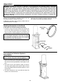
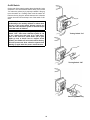
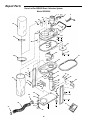
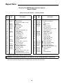
'& 2:1(5·60$18$/ '867&2//(&7,21 6<67(0 $VVHPEO\ 2SHUDWLRQ 5HSDLU3DUWV )RU<RXU6DIHW\ 5HDGDOOLQVWUXFWLRQVFDUHIXOO\ 48(67,21625&200(176" &$//5,'*,' Part No. SP6188 Printed in Taiwan Table Of Contents Safety Instructions for Dust Collection System............... 2 Before Using the Dust Collection System ...................... 3 Before Each Use ......................................................... 3 Introduction .................................................................... 4 Motor Specifications and Electrical Requirements ........ 4 Power Supply and Motor Specifications ..................... 4 General Electrical Connections ................................... 4 110-120 Volt, 60 Hz. Tool Information ........................ 4 Motor Safety Protection .............................................. 5 Wire Sizes ................................................................... 5 Unpacking and Checking Contents ............................... 6 Tools Needed .............................................................. 6 Unpacking ................................................................... 6 Loose Parts in Bag ...................................................... 6 Assembly ....................................................................... 7 Mounting Front Pivoting Casters ................................. 7 Mounting Rear Fixed Casters ..................................... 7 Mounting Inlet Guard .................................................. 8 Mounting Support Legs ............................................... 8 Mounting Leg Bracket ................................................. 8 Mounting Inlet Bracket ................................................ 9 Mounting Base Plate ................................................... 9 Mounting Filter/Dust Bag Holder to Filtration Housing .................................................... 10 Mounting Handle to Filtration Housing ...................... 10 Chip Bag Assembly - Lower Filtration Housing ........ 11 Upper Filter/Dust Bag Assembly ............................... 11 Operation ..................................................................... 12 Attaching Accessories to Inlet Guard ........................ 12 Connecting Dust Collection System to Power Source .......................................................... 12 On/Off Switch ............................................................ 13 Maintenance ................................................................ 14 Chip Collecting Bag Removal ................................... 14 Filter/Dust Bag Removal ........................................... 14 Motor ......................................................................... 15 Troubleshooting ........................................................... 15 Motor ......................................................................... 15 Notes ........................................................................... 17 Repair Parts ................................................................ 18 Safety Instructions for Dust Collection System • Do not use outdoors or on wet surfaces. • Put unit on a stable, level surface. • Route vacuum hose and electric cord out of traffic areas. • Do not allow to be used as a toy. Close attention is necessary when used by or near children. • Do not leave appliance plugged in. Unplug from outlet when not in use and before servicing. • To avoid injury from accidental starting, unplug power cord before changing or cleaning filter/dust bag or chip bag. • Do not use without filter/dust bag and/or chip bag in place. • Do not unplug by pulling on cord. To unplug, grasp the plug, not the cord. • Turn off controls before unplugging. • Do not use with damaged cord, plug or other parts. If your Dust Collection System is not working as it should, has missing parts, has been dropped, damaged, left outdoors, or dropped into water, return it to an Authorized Service Center. • Do not pull or carry by cord, use cord as handle, close a door on cord, or pull cord around sharp edges or corners. Do not run Dust Collection System over cord. Keep cord away from heated surfaces. • Do not handle plug or the Dust Collection System with wet hands. • Do not put any object into ventilation openings. Do not vacuum with any ventilation openings blocked; keep free of dust, lint, hair or anything that may reduce air flow. • Keep hair, loose clothing, fingers, and all parts of body away from openings and moving parts. Safety is a combination of common sense, staying alert and knowing how your dust collection system works. Read this manual to understand the dust collection system. Safety Signal Words DANGER: means if the safety information is not followed someone will be seriously injured or killed. WARNING: means if the safety information is not followed someone could be seriously injured or killed. CAUTION: means if the safety information is not followed someone may be injured. When using your Dust Collection System, follow basic safety precautions including the following. WARNING - To reduce the risk of fire, electric shock, or injury: Read and understand this owner’s manual and all labels on the Dust Collection System before operating. Use only as described in this manual. To avoid personal injury or damage to Dust Collection System, use only RIDGID recommended accessories. Sparks inside the electrical parts can ignite flammable vapors or dust. To avoid fire or explosion: • Do not vacuum, or use this Dust Collection System near flammable or combustible liquids, gases, gasoline or other fuels, lighter fluid, cleaners, oil-based paints, natural gas, hydrogen, or explosive dusts like coal dust, magnesium dust, grain dust, or gun powder. • Do not vacuum anything that is burning or smoking, such as cigarettes, matches, or hot ashes. • To reduce the risk of health hazards from vapors or dusts, do not vacuum toxic materials. • Do not use or store near hazardous materials. • To reduce the risk of electric shock, do not expose to rain. Store indoors. 2 CAUTION: If using this Dust Collection System to help keep airborne wood dust in heavy usage within acceptable limits, you must regularly monitor airborne dust and maintain Dust Collection System to avoid exceeding dust limits. Each application is unique. Your maintenance schedule must, therefore, be tailored to your specific use of the Dust Collection System. Before Using the Dust Collection System WARNING: To avoid mistakes that could result in serious, permanent injury, do not connect power cord until the following steps have been satisfactorily completed. • Assembly, mounting and alignment. • Learn the function and proper use of the ON-OFF switch. • Read and understand all safety instructions and operating procedures throughout the manual. • Read the following labels which appear on the top and bottom of filtration housing and sides of motor. Before Each Use • Remove switch key, and remove power supply cord from power supply. • Replace damaged, missing or failed parts before using the Dust Collection System again. • Connect to properly grounded outlet only. (See “Grounding Instructions” on page 14.) Inspect your Dust Collection System. • If any parts are missing, bent, or fail in any way, or any electrical components do not work properly, turn off the Dust Collection System. SAVE THESE INSTRUCTIONS The operation of any utility vac or blower can result in foreign objects being blown into the eyes, which can result in severe eye damage. Always wear safety goggles, not glasses, complying with ANSI Z87.1(or in Canada CSA Z94-3-M88) shown on package. Everyday eyeglasses have only impact resistant lenses. They are not safety glasses. Safety Goggles are available at many local retail stores. Glasses or goggles not in compliance with ANSI or CSA could seriously hurt you when they break. When cleaning collection bags, wear a dust mask. For dusty operations, wear dust mask. Use only extension cords that are rated for outdoor use. Extension cords in poor condition or that are too small in wire size can pose fire and shock hazards. When using an extension cord, be sure it is in good condition. Using any extension cord will cause some loss of power. To keep the loss to a minimum, use the following table to choose the minimum wire size extension cord. Extension Cord Length 0-50 Ft. 50-100 Ft. To reduce the risk of hearing damage, wear ear protectors when using the vac for extended hours or when, using it in a noisy area. 3 Gauge (A.W.G.) 14 12 Introduction The RIDGID Dust Collection System is specifically designed to capture sawdust and wood chips at the source. The fine dust is filtered by the upper bag while heavy particles settle in the lower bag for easy removal. Do not use as a vacuum. Do not attempt to clean, remove dust bags or service unit while in operation. Disconnect from power source. This Dust Collection System is intended for either commercial or household use. IMPORTANT NOTE Please Read Carefully CAUTION: The blower housing contains a high speed fan blade that can amputate fingers, grab loose clothing and neckties, or propel dust at high velocities. DO NOT OPERATE WITHOUT ALL PARTS IN PLACE. Static Shocks Are Common - in dry areas or when the relative humidity of the air is low. To reduce the frequency of static shocks in your home, the best remedy is to add moisture to the air with a console or installed humidifier. Motor Specifications and Electrical Requirements Power Supply and Motor Specifications The A-C motor used on this tool is an induction nonreversible type, having the following specifications: WARNING: To reduce the risk of electrical hazards, fire hazards or damage to the tool, use proper circuit protection. Your tool is wired at the factory for operation using the voltage shown. Connect tool to a power line with the appropriate voltage and a 15-amp branch circuit. Use a 15-amp time delay type fuse or circuit breaker. To reduce the risk of shock or fire, if power cord is worn or cut, or damaged in any way, have it replaced immediately. Horsepower Voltage Amperes Hertz (Cycles) Phase RPM Rotation of Shaft 1/2 110-120 8.2 60 Single 1725 Clockwise General Electrical Connections DANGER: To reduce the risk of electrocution: 1. Use only identical replacement parts when servicing. Servicing should be performed by a qualified service technician. 2. Do not use in rain or where floor is wet. This tool is intended for indoor residential use only. WARNING: Do not permit fingers to touch the terminals of plug when installing or removing the plug to or from the outlet. 110-120 Volt, 60 Hz. Tool Information NOTE: The plug supplied on your tool may not fit into the outlet you are planning to use. Your local electrical code may require slightly different power cord plug connections. If these differences exist refer to and make the proper adjustments per your local code before your tool is plugged in and turned on. In the event of a malfunction or breakdown, grounding provides a path of least resistance for electric current to reduce the risk of electric shock. This tool is equipped with an electric cord having an equipment grounding conductor and a grounding plug, as shown. The plug must be plugged into a matching outlet that is properly installed and grounded in accordance with all local codes and ordinances. Do not modify the plug provided. If it will not fit the outlet, have the proper outlet installed by a qualified electrician. A temporary adapter may be used to connect this plug to a 2-prong outlet, as shown, if a properly grounded three prong outlet is not available. This temporary adapter should be used only until a properly grounded three prong outlet can be installed by a qualified electrician. The green colored rigid ear, lug and the like, extending from the adapter must be connected to a permanent ground such as a properly grounded outlet box. NOTE: In Canada the use of a temporary adapter is not permitted by the Canadian electrical code. Improper connection of the equipment grounding conductor can result in a risk of electric shock. The conductor with insulation having an outer surface that is green with or without yellow stripes is the equipment grounding conductor. If repair or replacement of the electric cord or plug is necessary, do not connect the equipment-grounding conductor to a live terminal. 4 Motor Specifications and Electrical Requirements (continued) If the grounding instructions are not completely understood, or if you are in doubt as to whether the tool is properly grounded check with a qualified electrician or service personnel. 3-Prong Plug Properly Grounded Outlet WARNING: If not properly grounded, this tool can cause an electrical shock, particularly when used in damp locations, in proximity to plumbing, or out of doors. If an electrical shock occurs there is the potential of a secondary hazard, such as your hands to hit the cutting tool. Grounding Prong NOTE: The adapter illustrated is for use only if you already have a properly grounded 2-prong outlet. NOTE: In Canada the use of a temporary adapter is not permitted by the Canadian Electrical Code. Green Grounding Lug 3-Prong Plug Adapter Make sure this Is Connected to a Known Ground 2-Prong Outlet Motor Safety Protection IMPORTANT: To avoid motor damage, this motor should be blown out or vacuumed frequently to keep sawdust from interfering with normal motor ventilation. 1. Connect this tool to a power source with the appropriate voltage for your model and a 15-amp branch circuit with a 15-amp time delay fuse or circuit breaker. Using the wrong size fuse can damage the motor. 2. If the motor won’t start, turn the switch off immediately and unplug the tool. Check the quill to make sure it turns freely. If the quill is free, try to start the motor again. If the motor still does not start, refer to the "Motor Troubleshooting Chart." 3. Fuses may "blow" or circuit breakers may trip frequently if: a. Motor Is Overloaded-Overloading can occur if you feed too rapidly or make too many start/stops in a short time. b. Line voltages should not be more than 10% above or below the nameplate voltage. For heavy loads, however, the voltage at motor terminals must equal the voltage specified for your model. 4. Most motor troubles may be traced to loose or incorrect connections, overload, low voltage (such as small size wire in the supply circuit) or to overly long supply circuit wire. Always check the connections, the load and the supply circuit whenever motor doesn’t work well. Check wire sizes and length with the Wire Size Chart shown. Wire Sizes NOTE: Make sure the proper extension cord is used and is in good condition. The use of any extension cord will cause some loss of power. To keep this to a minimum and to prevent overheating and motor burnout, use the table at right to determine the minimum wire size (A.W.G.) extension cord. Use only 3-wire extension cords which have 3-prong grounding type plugs and 3-pole receptacles which accept the tools plug. 5 Extension Cord Length Gauge (A.W.G.) 0-25 25-50 51-100 16 14 12 Unpacking and Checking Contents Tools Needed Medium Screwdriver Adjustable Wrench Unpacking WARNING: To reduce the risk of injury, if any parts are missing, do not attempt to assemble the dust collection system, plug in the power cord, or turn the switch on until the missing parts are obtained and installed correctly. WARNING: To reduce the risk of injury from unexpected starting or electrical shock, do not plug the power cord into a source of power. This cord must remain unplugged whenever you are working on the dust collection system including assembly, cleaning and maintenance. Remove entire contents of carton. Check each item against the Carton Contents List. Contact 1-800-4RIDGID if any parts are damaged or missing. List of Loose Parts Loose Parts in Bag Key A B C D E F G H J K L M N O P Q R Description Qty. Hex Nut M6 x 1 ...........................................................5 Hex Nut 3/8-16............................................................2 Lockwasher 1/4...........................................................9 Lockwasher 5/16.........................................................8 Hex Screw M6 x 1-30..................................................4 Hex Screw M6 x 1-12..................................................6 Hex Screw M8 x 1.25-12...........................................18 Flat Washer 1/4 x 1/2..................................................7 Flat Washer 5/16 x 11/16 x 1/16 ...............................18 Flat Washer 3/8 x 3/4..................................................4 Switch Key ..................................................................1 Pivoting Caster ...........................................................2 Acorn Nut 3/8-16 ........................................................2 Fixed Caster ...............................................................2 Hose Clamp ................................................................2 A Description Qty. Filter/Dust Bag.....................................................1 Chip Collecting Bag .............................................1 Filter/Dust Bag Hanger ........................................1 Adjustable Band Clamp .......................................1 Handle .................................................................1 O-Ring .................................................................1 Inlet Guard...........................................................1 Bracket and Inlet Clamp ......................................1 Filtration Housing.................................................1 Left Side Support Leg..........................................1 Leg Bracket .........................................................1 Right Side Support Leg .......................................1 Base Plate ...........................................................1 Adapter ................................................................1 Flexible Hose, 4 Inch ...........................................1 Loose Parts Bag ..................................................1 Manual.................................................................1 C J N F G O K D M B P L E H Q 6 R Assembly Mounting Front Pivoting Casters 1. From the loose parts bag find the following: 2 Hex Nuts, 3/8-16 4 Flat Washers, 3/8 x 3/4 2 Acorn Nuts 3/8-16 2 Pivoting Casters 2. Find the following: 1 Base Plate Acorn Nut Hex Nuts 3/8-16 Pivoting Caster 3. Screw a hex nut completely onto the caster bolt. 4. Position flat washer on top of previously installed hex nut and slip the caster bolt through the hole on front of base plate. Position second flat washer on the bolt. 5. Screw the acorn nut on the bolt securely with an adjustable wrench. 6. Tighten the hex nut securely against the base plate. 7. Repeat steps 2-5 on opposite sides. Flat Washers 3/8 x 3/4 Base Plate Acorn Nut Flat Washer Flat Washer Hex nut Swivel Caster Bolt Base Plate (Front) Swivel Caster Mounting Rear Fixed Casters 1. From the loose parts bag find the following: 4 Hex Head Screws, M6 x 1-12 4 Lockwashers, 1/4 4 Flat Washers, 1/4 x 1/2 2 Fixed Casters Hex Head Screw M6 x 1-12 Lockwashers 1/4 Flat Washers 1/4 x 1/2 Fixed Caster Base Plate (Rear) 2. Position fixed caster under rear of base plate so that holes on caster bracket and base plate line up. 3. Install hex screw, lockwasher, and flat washer as shown. Tighten securely suing an adjustable wrench. 4. Repeat steps 2 and 3 on opposite sides. Hex Screw Lockwasher Flat Washer Fixed Caster 7 Assembly (continued) Mounting Inlet Guard 1. From the loose parts bag find the following: 4 Hex Screws, M8 x 1.25-12 4 Lockwashers, 5/16 4 Flat Washers, 5/16 x 11/16 x 1/16 2. Find the following: 1 Filtration Housing 1 Inlet Guard. 3. Carefully turn the filtration housing upside down so that the motor end bell rests against the floor. 4. Support the opposite side of filtration housing with a block of wood. A. Place O-ring in relief of inlet pipe. 5. Position inlet guard in line with the threaded holes on the base of the filtration housing. NOTE: Make sure inlet guard is pointing to rear of machine. 6. Place lockwasher and flat washer on hex screw and inset through the holes of the inlet guard into the threaded holes of the filtration housing as shown. 7. Complete the process for the other three holes using same method. Hex Head Screw M8 x 1.25-12 Lockwasher 5/16 Flat Washer 5/16 x 11/16 x 1/16 Guard must point to rear of machine Hex Screw Inlet Guard Flat Washer Lockwasher “O” Ring Filtration Housing (Upside Down) Mounting Support Legs 1. From the loose parts bag find the following: 4 Hex Screws, M8 x 1.25-12 4 Lockwashers, 5/16 4 Flat Washers, 5/16 x 11/16 x 1/16 2. Find the following: 1 Left Leg Support 1 Right Leg Support Hex Head Screw M8 x 1.25-12 Lockwasher 5/16 Flat Washer 5/16 x 11/16 x 1/16 Leg Support CAUTION: To avoid injury, keep hands away from fan blade. 3. Position left leg support as shown. 4. Place lockwasher and flat washer on hex screw and insert through the holes in the support leg and secure to the threaded holes in the filtration housing as shown. 5. Secure hex screws with adjustable wrench. Flat Washer Hex Screw Hex Screw Leg Bracket Mounting Leg Bracket 1. From the loose parts bag find the following: 4 Flat washers, 5/16 x 11/16 x 1/16) 4 Hex Screws*, M8 x 1.25-12 2. Find the following: 1 Leg Bracket 3. Insert leg bracket between the support legs and slide against the angled flange of the leg. NOTE: Make sure holes in leg bracket align with holes on leg support. Lockwasher Flat Washer Impeller Motor 4. Place Flat washer on hex screw, insert through angled flange of leg support and attach to threaded hole of bracket. Blocks of Wood 5. Repeat steps 2 and 3 using same process on other three holes. 8 Mounting Inlet Bracket 1. From the loose parts bag find the following: 4 Hex Screws, M8 x 1.25-12 4 Flat washers, 5/16 x 11/16 x 1/16) 2 Hex Screw M6 x 1-12 2 Flat washers 1/4 x 1/2 Hex Head Screw M8 x 1.25-12 Flat Washer 5/16 x 11/16 x 1/16 Hex Head Screw M6 x 1-12 2. Insert inlet bracket between relief flange of inlet guard and against inside edge of angle flange on support leg. Make sure both holes on bracket align with similar holes on leg support. 3. Place 5/16 flat washer on hex screw, insert through leg hole and attach to threaded hole of bracket. 4. Repeat same process for other hole and secure with use of adjustable wrench. 5. Attach fixed clamp as shown, by placing flat washer on hex screw, insert hex screw through hole of fixed clamp and attach to threaded hole of inlet guard bracket. 6. Repeat step 5 to attach other screw below inlet guard. 7. Tighten all screws on legs, inlet guard and filtration housing securely. Flat Washer 1/4 x 1/2 Clamp and Bracket Mount Here Inlet Guard Bracket Clamp Leg Support Mounting Base Plate 1. From the loose parts bag find the following items: 4 Hex Screws M8 x 1.25-12 4 Flat Washers 5/16 x 11/16 x 1/16 Hex Head Screw M8 x 1.25-12 Fixed Casters 2. Attach base plate to leg supports by flipping base upside down, aligning holes on both leg supports. 3. Place 5/16 flat washer on hex screw, insert through leg hole and attach to threaded hole of base plate as shown. 4. Repeat same process for other three holes and secure with use of adjustable wrench. 5. With the assistance of another person, carefully flip the dust collection system right side up. Base Plate Flat Washer 5/16 x 11/16 x 1/16 Swivel Casters Flat Washer Hex Screw Leg Support Leg Support 9 Assembly (continued) Mounting Filter/Dust Bag Holder to Filtration Housing 1. From the loose parts find the following items. 1 Dust Bag Holder 2. Press dust bag holder firmly into hole on guard impeller located inside filtration housing. Dust Bag Holder Filtration Housing Mounting Handle to Filtration Housing 1. From the loose parts bag find the following items. 4 Hex Screws M6 x 1-30 4 Lockwashers 1/4 4 Hex Nuts M6 x 1 2. Attach the ends of the handle to the relief flanges on the side of filtration housing as shown. 3. Insert hex screw through the handle and flange. 4. Attach the lockwasher and the hex nut to the screw and tighten. 5. Repeat process for all four holes and secure with adjustable wrench. Hex Head Screw M6 x 1-12 Hex Nut M6 x 1 Hex Head Screw Handle Lockwasher Hex Nut Relief Flange 10 Lockwasher 1/4 Dust Bag Holder Filtration Housing Chip Bag Assembly - Lower Filtration Housing Filtration Housing Sawdust Chute Extension 1. Insert lower chip bag by tilting the metal reinforced band at an angle and position it through the hole in the lower filtration housing. 2. Tuck one side of the band under the sawdust chute extension. 3. Allow the opposite side to rest on the ridge of the opening. 4. Tug on the chip bag to insure proper seating. Metal Reinforced Ring Chip Bag Upper Filter/Dust Bag Assembly 1. Disconnect the adjustable band clamp and insert the end through the loops provided at the opening of the filter/dust bag. 2. Invert the filter/dust bag and slip the open end of the bag over the 1" relief on the top opening of the filtration housing. 3. Secure the bag by adjusting the rectangular bar to the fourth set of hooks. 4. Pull the lever tight until it seats itself. Filter/Dust Bag CAUTION: Make sure the opening of the bag is tight against the relief so dust will not escape. Adjustable Band Clamp Filter/Dust Bag Holder Handle Relief 11 Operation WARNING: To reduce the risk of fire or explosion, do not operate this dust collection system in areas with flammable gases, vapors or explosive dust in the air. Flammable gases or vapors include but are not limited to; lighter fluid, solvent type cleaners, oil-base paints, gasoline, alcohol or aerosol sprays. Explosive dusts include but are not limited to; coal, magnesium, grain or gun powder. Do not vacuum explosive dust, flammable or combustible liquids or hot ashes. To reduce the risk of health hazards from vapors or dusts, do not vacuum toxic materials. To reduce the risk of electric shock, do not expose to rain. Store indoors. To reduce the risk of injury from accidental starting, unplug power cord before changing, cleaning or emptying filter/ dust bag or chip bag. This dust collection system is designed to be connected directly to the woodworking machines. Please, use only the parts provided for maximum efficiency. 4" Diameter x 60" Hose. PVC vulcanized rubber with wire reinforcement and 2-4" clamps. 4"/2-1/2" Diameter Adapter. This connector allows direct hookup to many machines including band saws, belt and disc sanders and radial saw sawdust collector. Attaching Accessories to Inlet Guard 4" Diameter hose/clamp assembly and adapter. Over-Center Clamp 1. Lift lever to open over-center clamp. Place clamp over end of hose. Slide hose/clamp over inlet-guard. Push lever on clamp to tighten clamp onto inlet-guard. Use same process to connect adaptor to other end of hose. CAUTION: To reduce the risk of fire, use only the hose and adaptor designed for this unit. The adaptor is designed to fit only to the hose. Do not attach it directly to any other inlet opening. Inlet Guard Clamp Hose Clamp Adapter Connecting Dust Collection System to Power Source CAUTION: If connected to a circuit protected by fuses, use time delay fuses with this appliance. 1. Prior to connecting your dust collection system to any power source, be sure your bags are installed properly. This will remove any possibility of dust flying in your face. 2. The motor on your dust collection system is wired for 120 volts, single phase power system. Make sure the motor rating agrees with the electrical system it is to be connected to. 3. Too many machines on one circuit will blow fuses. Be careful not to overload circuit. 12 On/Off Switch On the rear of the motor housing above the handle, is the switch box. The On/Off switch has the ability to be turned “On” when the yellow key is properly installed. Lifting up turns the switch on. Pushing down turns the switch off. Remove the key from the switch whenever the collection system is turned “Off” and keep it out of the reach of children. WARNING: The dust collection system can start accidentally or be used by children or others when the key is left in the switch. Always remove key when the dust collection system is off and keep it out of the reach of children. WARNING: For your own safety, always push the switch “OFF” when dust collection system is not in use, remove key and keep it in a safe place, also, in the event of a power failure (all of your lights go out) or blown fuse or tripped circuit breaker, turn switch off, lock it and remove the key. This will prevent the dust collection system from starting up again when the power comes back on. Turning Switch “On” Turning Switch “Off” Removing Switch Key 13 Maintenance WARNING: For your own safety, turn switch “OFF” and remove plug from power source outlet before maintaining or lubricating your sawdust collection system. WARNING: To reduce the risk of injury from electric shock or suddenly starting unit, always remove switch key and keep unplugged while unit is disassembled in any way. Always reassemble with recommended parts before plugging unit in. Chip Collecting Bag Removal 1. Push band up and slide opposite edge to the middle opening. 2. Lower band carefully through opening as shown. Deposit chips in appropriate container. CAUTION: Wear safety goggles ANSI Z87.1 (or in Canada CSA Z94-3-M88) to protect your eyes prior to commencing operation. 3. Reconnect the chip collecting bag by sliding the band through the hole and slide the opposite side under dust chute extension. Seat as shown. Chip Bag Filter/Dust Bag Removal CAUTION: If using this dust collection system to help keep airborne wood dust in heavy usage within acceptable limits, you must regularly monitor airborne dust and maintain dust collection system to avoid exceeding dust limits. Each application is unique. Your maintenance schedule must, therefore, be tailored to your specific use of this dust collection system. Dust Bag Dust Bag Holder 1. Shake the filter/dust bag so the fine dust falls into lower chip collecting bag. 2. Disconnect the adjustable band clamp by releasing the spring lever clamp. 3. Remove the filter/dust bag and deposit all fine dust in an appropriate container. 4. Reconnect the bag carefully so the clamp wraps around the bag on all sides. Adjust the lever to the fourth hook and fasten securely. 14 Adjustable Band Clamp Motor To remove dust, blow off motor with a low pressure air hose. Excessive dust in motor could cause excessive heat in motor. Every effort should be made to prevent foreign material from entering the motor. When operated under conditions likely to permit accumulations of dust, dirt or waste within the motor, a visual inspection should be made at frequent intervals. Accumulations of dry dust can usually be blown out successfully. NOTE: Motors used on wood working tools are particularly susceptible to the accumulation of sawdust and wood chips and should be blown out or “vacuumed” frequently to prevent interference with normal motor ventilation. CAUTION: To reduce the risk of eye injury or adverse reaction to dust, high air pressure should not be used, especially in poorly ventilated areas. The operator performing this cleaning function should wear safety goggles and filter mask. Do not use unit if power cord becomes worn or frayed. If any servicing (other than the above cleaning) becomes necessary, it should be performed by an Authorized RIDGID Service Center. NOTE: The speed of this motor cannot be regulated or changed. Troubleshooting WARNING: For your own protection, turn switch “OFF” and always remove plug from power source outlet before troubleshooting. Motor Trouble Motor will not run. Probable Cause Remedy 1. Defective cord, plug, switch and/or motor. 1. Consult an Authorized Service Center. Any attempt to repair this motor may create a hazard unless repair is done by a qualified service technician. 2. Check for blown fuses and replace with fuse of proper capacity. 2. Blown fuse. Excessive sawdust in air. 1. Loose connectors 2. Filter/dust bag and/or chip collection bag releasing sawdust. 1. Tighten connections. 2. a. Sawdust trapped between clamp bag and housing. b. Lower bag is hung up on sawdust shoot extension. Reposition chip bag properly. See “Maintenance - Chip Bag”. Excessive impeller noise. 1. Picked up large wood chips or debris. 1. Do not pick up metal or ferrous materials. Stop the machine and the material will fall to the bottom of inlet tube. 2. Unplug unit prior to disassembly. Hazardous moving parts inside. Attach inlet guard before plugging in. Use a piece of wood to free impeller. 3. Consult Authorized Service to repair loose or rubbing impeller. A repair to the housing may create a hazard unless it is done by a qualified service technician. 2. Loose impeller. 3. Rubbing impeller. Excessive noise. 1. Motor 1. Have motor checked by qualified service technician. 15 Troubleshooting (continued) Motor (continued) Trouble Probable Cause Remedy Motor fails to develop full 1. Circuit overloaded with power. NOTE: LOW VOLTlights, appliances and other AGE: (Power output of motors. motor decreases rapidly 2. Undersize extension cord or with decrease in voltage at extension cord too long. motor terminals. For example, a reduction of 3. General overloading of 10% in voltage causes a power company facilities. reduction of 19% in maximum power output of which the motor is capable and a reduction of 20% in voltage causes a reduction of 36% in maximum power output.) 1. Do not use other appliances or motors on same circuit when using the Dust Collection System. 2. Increase the wire sizes on extension cords, or reduce length of extension cords. See “Motor Specifications and Electrical Requirements” section. 3. Request a power check from the power company. Motor starts slowly or fails to come up to full speed. 1. Low voltage. 1. Request voltage check from the power company. 2. Windings burned out or 2. Have motor repaired by a qualified service techniopen. cian. 3. Starting switch will not oper- 3. Have capacitor replaced by a qualified service techate. (Switch contacts worknician. ing properly.) Capacitor is bad. Motor overheats 1. Motor overloaded. 1. Clean out sawdust to provide normal air circulation through motor. See “Maintenance” section. 2. Improper cooling. (Air circulation restricted through motor due to sawdust, accumulating inside of motor.) Motor stalls (resulting in blown fuses or tripped circuit breakers). Frequent opening of fuses or circuit breakers. 1. Voltage too low to permit motor to reach operating speed. 2. Fuses or circuit breakers do not have sufficient capacity. 1. Request voltage check from the power company. 1. Motor overloaded. 2. Fuses or circuit breakers do not have sufficient capacity. 1. Install proper size fuses or circuit breakers. 2. Install proper size fuses or circuit breakers. NOTE: Motors used on woodworking tools are particularly susceptible to the accumulation of sawdust and wood chips and should be blown or “vacuumed” frequently to prevent interference with normal motor ventilation of the centrifugally operated starting switch. 16 Notes 17 Repair Parts Parts List For RIDGID Dust Collection System Model DC20000 1 2 3 4 5 6 49 50 48 47 7 46 9 8 10 42 11 45 12 13 42 14 17 15 12 16 18 20 19 44 21 22 27 23 23 16 26 15 24 42 43 41 28 25 26 27 25 27 27 25 29 16 40 12 27 36 25 39 15 35 30 38 35 37 51 34 31 32 33 18 Repair Parts Parts List For RIDGID Dust Collection System Model DC20000 Always order by Part Number - not by Key Number Key No. 1 2 3 4 5 6 7 8 9 10 11 12 13 14 15 16 17 18 19 20 21 22 23 24 25 26 27 * Part No. 826690 826395 * 826123 826122 819189-1 819173 826692 * 819192 819171-1 * * 819183 * * 819176 819198-1 * 826691 819190-1 819182-1 819195 819194 * * * Description •Motor, 1 H.P. Bezel Switch Screw Hex hd. M6 x 1.0-20 Switch Key, Switch Cord with Plug Seal, Motor Handle Screw, Hex Hd. M6x1-30 Plug, Plastic Housing, Upper Lockwasher, 1/4 Nut, Hex M6 x 1 Seal, Housing Washer, 1/4 x 1/2 x 1/16 Screw, Hex M6 x 1-12 Impeller Washer, 5/8 x 1-1/2 x 1/8 Nut, Hex 5/8-18 Guard, Impeller Sleeve, Housing Edge Housing, Lower O-Ring, 137mm Pipe, Inlet Washer, 5/16 x 11/16 x 3/32 Lockwasher 5/16 Screw, Hex Hd. M8 x 1.25-12 Key No. Part No. 28 29 30 31 32 33 34 35 36 37 38 39 40 41 819202-1 819201-1 819196-1 819207 819199-1 819203 42 43 44 45 46 47 48 49 50 51 * * * 826693 819267 819269 819200-1 * * 819170-1 819169-1 826689 826677 * 819174 819167 819188 SP6188 Description Clamp, Inlet Support Bracket, Inlet Support Leg Caster, Fixed Base Caster, Pivoting Nut, Hex 3/8-16 Washer, Flat 3/8 x 3/4 x 3/32 Nut, Acorn 3/8-16 Clamp, Hose Hose, Flex 4.0 Inch Adapter 2-1/2”/4.0” Bracket, Leg Screw, Pan Hd. M4 x 16-12 Ty “AB” Screw, Pan Hd. M4 x 16-10 Ty “B” Bag, Lower Chip Clamp, Filter/Dust Bag Holder, Dust Bag Bag, Upper Filter/Dust Screw, Pan Hd. M4 x 0.7-10 Cover, Capacitor Capacitor Key Owners Manual Standard Hardware Item - May be Purchased Locally. WARNING: These Items Are Important To The Safety Of This Tool. Do Not Substitute Common Parts. • Any attempt to repair or replace electrical parts on this unit may create a HAZARD unless repair is done by a qualified service technician. Repair service is available at an Authorized Service Center. 19 Lifetime Warranty On RIDGID Tools The RIDGID REPUTATION is the result of the consistent product quality and years of pride in workmanship. Rigorous checks and controls from raw materials to packaged products insure product confidence widely accepted as the mark of the professional trades. Therefore, RIDGID covers its products with a LIFETIME WARRANTY against defects in material or workmanship. To take advantage of this warranty, the complete product must be delivered prepaid to RIDGE TOOL COMPANY or any RIDGID AUTHORIZED SERVICE CENTER. Obviously, failures due to misuse, abuse or normal wear and tear are not covered by this warranty. NO OTHER WARRANTY, WRITTEN OR ORAL, APPLIES. No employee, agent, dealer or other person is authorized to give any warranty on behalf of RIDGID Dust Collection System, Emerson Electric Co. Warranted products will be repaired or replaced, at our option, at no charge to you and returned to you via prepaid transportation. Such replacement or repair is the exclusive remedy available from RIDGID Dust Collection System, Emerson Electric Co. Emerson Electric Co. is not liable for damage of any sort, including incidental and consequential damages. Some U.S.A. states do not allow the exclusion or limitation of incidental or consequential damages, so the above limitation or exclusion may not apply. This warranty gives you specific legal rights, and you may have other rights which vary from state to state. Stock No. DC2000 Model No. DC20000 The model and serial number of your Dust Collection System may be found on the motor cover. You should record both model and serial number in a safe place for future use. QUESTIONS OR COMMENTS? CALL 1-800-4-RIDGID RIDGID Power Tools Emerson Electric Co. © 1998 Emerson Electric Co. Part No. SP6188 Form No. SP6188 Printed in Taiwan 8/98