1
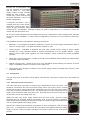
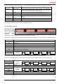
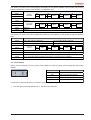
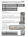
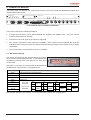
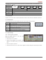
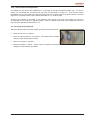
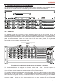
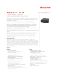
5. CPU MODULE
A VideoBloX system is controlled from a single master CPU module. For an expanded system, with multiple
chassis, it is possible to interconnect the chassis and have a single CPU module control the entire system.
Front and Rear Views of CPU Module
All system configuration is carried out by means of a PC running Windows 95 / 98 / 98SE / 2000 / XP or NT,
which connects to the CPU module. Once configuration is complete, the PC may optionally be detached or
used as a system activity logger. All configuration information is stored in non-volatile memory and is retained
during a power loss of up to one month.
The CPU module oversees the operation of all modules installed into a chassis or sub-chassis. The software
/ operating system is installed into this module. The following hardware sub-systems are located within this
module:
z
High speed processor core
z
EPROM memory to hold system firmware
z
Non-volatile RAM memory to store system variables, configuration and downloaded system code
extensions
z
Watchdog timer and supply voltage monitor to automatically restart system operation in the event of
supply brownouts or software malfunction
z
Various decoding logic
z
Power supplies for the CPU module only, including isolated supplies for the two communication
channels which connect to external equipment
z
Six serial communication channels
z
32 Alarm inputs
z
4 Alarm relay outputs
z
DIP switches for COM channel settings
Front panel indications provide basic information relating to the systems overall health and communications
activity.
It is possible to install multiple CPU modules into a single chassis. Should this be a requirement then an
additional CPU arbitration module must be installed. The arbitration module re-routes the major CPU
communications channels to the configuration PC and the field. Should a CPU failure be detected by the
arbitration module, the system can automatically switch over to the backup CPU.
Limited alarm inputs (32) and relay outputs (4) are provided on this module. Inputs and outputs may readily
be expanded by the addition of the relevant I2C expansion modules or remote expansion via the RS422
serial communications link. Up to 256 alarm inputs and 256 alarm outputs are supported.
VideoBloX User’s Manual Ver. 2.00
Page 7