1
&/(-*4)
+056#..#6+10
/#07#.
7*'#/%
7*)#/%
7*)#/%
10356(6³4
*5"-*"/0
'3"/±"*4
&*'#/%
&*'#/%
&*'#/%
&41"º0-
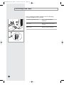
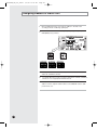
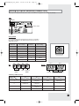
+PFQQT7PKV1WVFQQT7PKV
3644*"/
&ơơ)/*,"
%&654$)
5[UVGO#KT%QPFKVKQPGT
' 5 ( + 2 & ) 4 &$#
2
&$#A'KPFF
'
DH140GZM_IM_E/O_25844
3/3/06 10:24 AM
Page 2
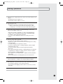
Safety Precautions
The following safety precautions must be taken when using your air conditioner.
WARNING
INSTALLING
THE UNIT
• Risk of electric shock Can cause injury or death. • Disconnect all
remote electric power supplies before servicing, installing or cleaning.
• This must be done by the manufacturer or its service agent or a similar
qualified person in order to avoid a hazard.
◆ The unit should not be installed by the user. Ask the dealer or authorized
company to install the units except room air conditioners for the U.S.A and
Canada area.
◆ If the unit is installed improperly, water leakage, electric shock or fire may
result.
◆ Mount with the lowest moving parts at least 2.5 m above the floor or grade
level. (If applicable)
◆ The manufacturer does not assume responsibility for accidents or injury
caused by an incorrectly installed air conditioner. If you are unsure about
installation, contact an installation specialist.
◆ When installing the built-in type air conditioner, keep all electrical cables
such as the power cable and the connection cord in pipe, ducts, cable
channels e.t.c to protect them against liquids, outside impacts and so on.
◆ This appliance is not accessible to the general public. This appliance
should be installed according to the provided installation
instruction.
POWER SUPPLY LINE,
FUSE OR CIRCUIT
BREAKER
◆ If the power cord of this air conditioner is damaged, it must be replaced by
the manufacturer, its service agent or similarly qualified persons in order to
avoid a hazard.
◆ The unit must be plugged into an independent circuit if applicable or
connect the power cable to the auxiliary circuit breaker. An all pole
disconnection from the power supply must be incorporated in the fixed
wiring with a contact opening of >3mm.
◆ Do not use an extension cord with this product.
◆ If the unit is equipped with a power supply cord and a plug, the plug must
be accessible after installation.
◆ The air conditioner must be installed in accordance with national wiring
regulations and safety regulations wherever applicable.
E-2
DH140GZM_IM_E/O_25844
3/3/06 10:24 AM
Page 3
Contents
■
■
■
■
■
■
■
■
■
■
■
■
■
■
■
■
■
■
■
■
■
■
■
Preparation for Installation ............................................................................
Deciding on Where to Install the Air Conditioner ........................................
Indoor Unit Installation ................................................................................
Purging the Unit ..........................................................................................
Connecting the Connection Cord ................................................................
Connecting the Cables to the Outdoor Unit ................................................
Drain Hose Installation ................................................................................
Connecting the Indoor Unit Assembly Piping ..............................................
Cutting/Flaring the Pipes .............................................................................
Checking Correct Grounding .......................................................................
Fixing the Unit in Position ...........................................................................
Connecting Up and Removing Air In the Circuit .........................................
Performing Leak Tests ................................................................................
Insulation .....................................................................................................
Adjusting Air Flow ........................................................................................
Setting Up the Model Option .......................................................................
Assigning Address to Indoor Unit ................................................................
Additional Functions ....................................................................................
Drain Pump Installation (Optional) ..............................................................
Setting Up Option Switches (Outdoor unit) .................................................
Testing Operations ......................................................................................
Troubleshooting ..........................................................................................
Parts List ...................................................................................................
4
5
10
11
12
14
15
17
18
19
20
21
22
23
24
25
28
29
31
33
35
36
40
E-3
DH140GZM_IM_E/O_25844
3/3/06 10:24 AM
Page 4
Preparation for Installation
When deciding on the location of the air conditioner with the owner,
the following restrictions must be taken into account.
General
Do NOT install the air conditioner in a location where it will come into
contact with
the following elements:
◆
◆
◆
◆
◆
Combustible gases
Saline air
Machine oil
Sulphide gas
Special environmental conditions
If you must install the unit in such conditions, first consult your dealer
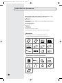
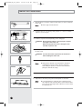
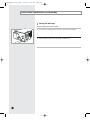
Accessories
◆ The following accessories are supplied with the indoor unit.
The type and quantity may differ depending on the specifications.
Owner’s
Instructions(1)
Installation
Manual(1)
Insulation Cover
Pipe in(1)
Insulation Cover
Pipe out(1)
Insulation Drain (1)
Insulation Cover
Drain(1)
Insulation Pipe in(1)
Insulation Pipe out(1)
Cable-Tie(8)
Flexible hose(1)
Clamp hose(2)
Rubber(8)
Wired Remote Controller Accessories
Wired remote controller
Cable-Tie
Cable Clamp
M4 x 16 Tapped
Screws
Indoor unit power
drawing cable
Communication cable of
the wired remote
controller
Wire joint
Owner’s Instruction
Installation Manual
E-4
DH140GZM_IM_E/O_25844
3/3/06 10:24 AM
Page 5
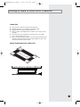
Deciding on Where to Install the Air Conditioner
Indoor Unit
◆
◆
◆
◆
There must be no obstacles near the air inlet and outlet.
Install the indoor unit on a ceiling that can support its weight.
Maintain sufficient clearance around the indoor unit.
Make sure that the water dripping from the drain hose runs away correctly
and safely.
◆ The indoor unit must be installed in this way, that they are out of public
access. (Not touchable by the users)
◆ After connecting a chamber, insulate the connection part between the indoor
unit and the chamber with t10 or thicker insulation. Otherwise, there can be
air leak or dew from the connection part.
5mm
Space Requirements for Indoor Unit
E-5
DH140GZM_IM_E/O_25844
3/3/06 10:24 AM
Page 6
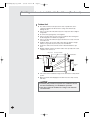
Deciding on where to install the Air Conditioner (Continued)
Outdoor Unit
◆ The outdoor unit must not be placed on its side or upside down, as the
compressor lubrication oil will run into the cooling circuit and seriously
damage the unit.
◆ Choose a location that is dry and sunny, but not exposed to direct sunlight or
strong winds.
◆ Do not block any passageways or thoroughfares.
◆ Choose a location where the noise of the air conditioner when running and
the discharged air do not disturb any neighbours.
◆ Choose a position that enables the pipes and cables to be easily connected
to the indoor unit.
◆ Install the outdoor unit on a flat, stable surface that can support its weight
and does not generate any unnecessary noise and vibration.
◆ Position the outdoor unit so that the air flow is directed towards the open
area.
◆ Maintain sufficient clearance around the outdoor unit, especially from a radio,
computer, stereo system, etc.
Indoor Unit
Remote Controller
1m or m
ore
1m or more
Circuit Breaker
ore
1.5m or m
Circuit Breaker
re
mo e
or
r
m r mo
1.5
o
m
5
1.
re
or mo
1.5m
Outdoor
Unit
Stereo
◆ If the outdoor unit is installed at a height, ensure that its base is firmly fixed in
position.
◆ Make sure that the water dripping from the drain hose runs away correctly
and safely.
CAUTION
◆ You have just purchased a system air conditioner and it
has been installed by your installation specialist.
◆ This device must be installed according to the national
electrical rules.
E-6
DH140GZM_IM_E/O_25844
3/3/06 10:24 AM
Page 7
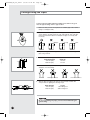
d)
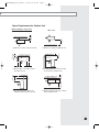
Space Requirements for Outdoor Unit
Unit : mm
2000 or more
600 or more
❋ When 3 sides of the outdoor unit are
blocked by the wall
1500 or more
300 or more
❋ The upper part of the outdoor unit and
the air outlet is towards the wall
300 or more
150 or more
500 or more
❋ When the air outlet is towards the wall
1500 or more
200 or more
❋ When the air outlet is opposite the wall
1500 or more
150 or more
When installing 1 outdoor unit
❋ The upper part of the outdoor unit
and the air outlet is opposite the wall
❋ When front and rear side of the outdoor
unit is towards the wall
E-7
DH140GZM_IM_E/O_25844
3/3/06 10:24 AM
Page 8
Deciding on where to install the Air Conditioner (Continued)
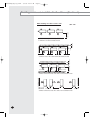
When installing more than 1 outdoor unit
1500 or more
Unit : mm
200 or more
❋ When the air outlet is towards the wall
300 or more
600 or more
600 or more
600 or more
600 or more
600 or more
1500 or more
200 or more
❋ When 3 sides of the outdoor unit are blocked by the wall
❋ When front and rear side of the outdoor unit is towards the wall
1500 or more
600 or more
3000 or more
3000 or more
❋ When front and rear side of the outdoor unit is towards the wall
E-8
200 or more
DH140GZM_IM_E/O_25844
3/3/06 10:24 AM
Page 9
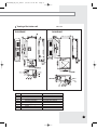
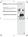
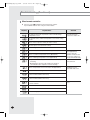
&TCYKPIQHVJGKPFQQTWPKV
2JEPġII
&*EAMC
0WODGT
0COG
.KSWKFRKRGEQPPGEVKQP
)CURKRGEQPPGEVKQP
&TCKPRKRGEQPPGEVKQP
&TCKPRKRGEQPPGEVKQP
2QYGTUWRRN[EQPPGEVKQP
#KTFKUEJCTIGHNCPIG
#KTHKNVGT
*QQM
&*EA/C
&GUETKRVKQP
«(NCTG
«(NCTG
1&+&
7UKPIFTCKPRWOR
1RVKQPCN
(QT/`/
E-9
DH140GZM_IM_E/O_25844
3/3/06 10:24 AM
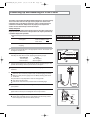
Page 10
Indoor Unit Installation
1
Mark the place to insert the suspension bolt where you want to install the
indoor unit.
Note
Concrete
◆ Refer to page 9 for the dimension.
2
Insert bolt anchors. Use existing ceiling supports or construct a suitable
support as shown in figure.
3
Install the suspension bolts depending on the ceiling type.
Insert
Hole in anchor
Hole in plug
Suspension bolt(M8)-field supply
IMPORTANT Ensure that the ceiling is strong enough to support
the weight of the indoor unit.
Before hanging the unit, test the strength of each
attached suspension bolt.
Ceiling support
4
Screw eight nuts to the suspension bolts making space for hanging
the indoor unit.
IMPORTANT You must install the suspension bolts more than 4
when installing the indoor unit.
5
Hang the indoor unit to the suspension bolts between two nuts.
Note
6
Screw the nuts to suspend the unit.
7
Adjust level of the unit by using measurement plate for all 4 sides.
Note
10mm
Drain hose connection port
E-10
◆ Tubing must be laid and connected inside the ceiling when
suspending the unit. If the ceiling is already constructed,
lay the tubing into position for connection to the unit before
placing the unit inside the ceiling.
◆ For proper drainage of condensate, give a 10mm slant to the
left or right side of the unit which will be connected with the drain
hose, as shown in the figure. Make a tilt when you wish to install
the drain pump, too.
DH140GZM_IM_E/O_25844
3/3/06 10:24 AM
Page 11
Purging the Unit
On delivery, the indoor unit is loaded with an inert nitrogen gas.
All this gas must therefore be purged before connecting the assembly
piping. To purge the inert gas, proceed as follows.
Unscrew the caps at the end of each pipe.
Result:
Note
All inert gas escapes from the indoor unit.
◆ To prevent dirt or foreign objects from getting into the pipes
during installation, do NOT remove the caps completely until
you are ready to connect the piping.
E-11
DH140GZM_IM_E/O_25844
3/3/06 10:24 AM
Page 12
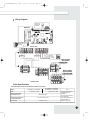
Connecting the Connection Cord
1DAEJ@KKNQJEPEOLKSANA@BNKIPDAKQP@KKNQJEPRE=PDA?KJJA?PEKJ?KN@
4GOQXGVJGUETGYQPVJGGNGEVTKECNEQORQPGPVDQZCPFTGOQXGVJGEQXGT
RNCVG
4QWVGVJGEQPPGEVKQPEQTFVJTQWIJVJGUKFGQHVJGKPFQQTWPKVCPFEQPPGEV
VJGECDNGVQVGTOKPCNUCUUJQYPKPRCIG
4QWVGVJGQVJGTGPFQHVJGECDNGVQVJGQWVFQQTWPKVVJTQWIJVJGEGKNKPI
VJGJQNGQPVJGYCNN
4GCUUGODNGVJGGNGEVTKECNEQORQPGPVDQZEQXGTECTGHWNN[VKIJVGPKPIVJG
UETGY
0QVG
9JGPEQPPGEVKPIVJGECDNGU[QWOWUVRCUUVJGOVJTQWIJ
VJGECDNGENCORVQHKZVJGOUGEWTGN[
%QPPGEVVJG%QPPGEVKQP%QTFCUUGGPKPnextRKEVWTG
CPFVJGVQTSWGQHUETGYKU`MIHŖEO
E-12
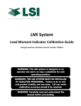
$(':-?)-?%/? !- 0AGE 9KTKPI&KCITCO
4GEGKXGT
&KURNC[7PKV
1RVKQPCN
/#+02%$
(NQCV5YKVEJ
&TCKP2WOR
1RVKQPCN
+PFQQT7PKV
/ 1
9F
9F
9Z 9Z
)
)
9
9
)
)
9KTGF
4GOQVG
%QPVTQNNGT
%QOOWPKECVKQP
2QYGT
/#+0219'4
7*'#/%
8`*\
)
)
/#+0219'4
7*)#/%
%
Ó
8`*\
8` *\
1WVFQQT7PKV
%CDNG5RGEKHKECVKQPU
1DABKHHKSEJCAHA?PNE?=H ?D=N=?PANEOPE?OIQOP>ANAOLA?PA@
/1&'.
2QYGT
+PFQQTWPKVRQYGTECDNG
%QOOWPKECVKQPECDNG
9KTGFTGOQVGEQPVTQNNGTRQYGT
EQOOWPKECVKQPECDNG
2QYGTECDNG
&*'#/%7*'#/%
&*'#/%&*'#/%
7*)#/%7*)#/%
Ó 8`*\
Ó 8`*\
OOw
%8YKTG
`OO
%8YKTG
OOw
%8YKTG
0QVG
6JGRQYGTECDNGUCTGPQV
UWRRNKGFYKVJVJGCKT
EQPFKVKQPGT
6JGWUGTUJQWNFRWTEJCUG
VJGOUGRCTCVGN[
6JGRQYGTECDNGUWUGVJG
ITCFG*40(QT
*40(OCVGTKCNU
'
DH140GZM_IM_E/O_25844
3/3/06 10:24 AM
Page 14
Connecting the Cables to the Outdoor Unit
Two electric cables must be connected to the outdoor unit.
◆ The connection cord connecting the indoor unit to the outdoor unit
◆ The power cable connecting the auxiliary circuit breaker to the
outdoor unit
0QVG
6JGEQPPGEVECDNGUUJQWNFDGKPEGTV
HTQOVJGHTQPVWUGTWDDGTYKTGVQ
RTQVGEVVJGECDNGU
7UGJQNFYKTGVQHCUVGPVJGECDNGU
GPUWTGVJGECDNGUECPPQVVQWEJ
VJGEQORCPFRKRGU
E-14
1
Remove the terminal board cover on the side of the outdoor unit.
2
Connect the connection cord and power cable to terminals as shown in the
diagram.
3
Connect the power cable to the auxiliary circuit breaker.
4
Replace the terminal board cover, carefully tightening the screw.
CAUTION
◆ Keep the power cable and the connection cord in a
steel pipe to protect them against liquids, outside
impacts and so on.
DH140GZM_IM_E/O_25844
3/3/06 10:24 AM
Page 15
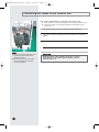
Drain Hose Installation
Care must be taken when installing the drain hose for the indoor unit
to ensure that any condensate water is correctly drained outside. The
drain hose can be installed to the right of the base pan.
Drain hose connection port
1
Unscrew the 4 tapped screws to remove the cover of the drain hose
connection port.
2
Insert the flexible hose to the drain hose port.
Note
3
Cable
Clamp
◆ Fix the flexible hose to the indoor unit with the supplied cable
clamp securely.
(Use the screwdriver to fix the flexible hose securely.)
Install the drain hose so that its length can be as short as possible.
Internal diameter of the drain hose should be the same or slightly bigger
than the external diameter of the drain hose port.
◆ Inner diameter of the drain hose
Indoor
Unit
Cable-Tie
32mm(Inner diameter)
Note
CAUTION
Must fit tightly against
body without any gap.
◆ Fix the flexible hose to the PVC with the supplied cable tie
securely.
4
Insulation drain hose
Insulation cover drain
◆ Give a slightly slant to the drain hose for proper drainage of
condensate.
Wrap the drain hose with the insulation drain as shown in figure and secure it.
No gap
CAUTION
When not installing the drain pump
When installing the drain pump
Do not give the hose and upward gradient
after the connection port.
This will cause water to flow backwards when
the unit is stopped, resulting in water leaks.
If it is necessary to increase the height of the
drain hose somewhat, the portion directly after
75cm. If it is raised higher than 75cm, there can
be water leaks.
Upward gradient
75cm or less
Ceiling
Ceiling
Do not apply force to the piping on the unit side
when connecting the drain hose. The hose should
not be allowed to hang loose from its connection to
the unit. Fasten the hose to a wall, frame or other
support as close to the unit as possible.
Support pieces
Ceiling
E-15
DH140GZM_IM_E/O_25844
3/3/06 10:24 AM
Page 16
Drain Hose Installation (Continued)
Testing the drainage
Prepare a little water about 5 liters.
E-16
1
Pour water into the base pan in the indoor unit as shown in figure.
2
Confirm that the water flows out through the drain hose.
DH140GZM_IM_E/O_25844
3/3/06 10:24 AM
Page 17
Connecting the Indoor Unit Assembly Piping
There are two refrigerant pipes of differing diameters:
◆ A smaller one(9.52mm, 3/8") for the liquid refrigerant
◆ A larger one(19.05mm, 3/4") for the gas refrigerant
A
Gas refrigerant port
◆ The thickness of tube should not less than 1.0mm.
◆ The inside of copper tube must be clean & has no dust.
The connection procedure for the refrigerant pipes varies according to
the exit position of the pipes from the indoor unit, as seen when facing
the indoor in the “A” side.
Liquid
refrigerant port
Drain hose connection port
◆ Liquid refrigerant port
◆ Gas refrigerant port
◆ Drain hose connection port
1
Remove the pinch pipe on the pipes and connect the assembly pipes to
each pipe, tightening the nuts, first manually and then with a torque
wrench, a spanner applying the following torque.
Outer Diameter
9.52 mm (3/8")
19.05 mm (3/4")
Note
2
Torque
250~280 kgf•cm
990~1210 kgf•cm
◆ If the pipes must be shortened refer to page 18.
a. When the indoor unit is above the outdoor
unit
Indoor unit
Must use insulator which is thick enough to cover the refrigerant tube to
protect the condensate water on the outside of pipe falling onto the floor
and the efficiency of the unit will be better.
Outdoor unit
3
Cut off any excess foam insulation.
4
Be sure that there must be no crack or wave on the bended area.
5
It would be necessary to double the insulation thickness (10mm or more)
to prevent condensation even on the insulator when if the installed area is
warm and humid.
6
Shape an oil trap as shown in figure the oil trap must be formed every
level difference of 10m.
Oil trap (Must be install
every 10m)
b. When the outdoor unit is above the indoor
unit
Outdoor unit
Oil trap(Must be installed
every 10m)
Indoor unit
Radius
5cm
Oil trap
(suction tube)
E-17
DH140GZM_IM_E/O_25844
3/3/06 10:24 AM
Page 18
Cutting/Flaring the Pipes
Connect the pipe within 50m and cutting pieces will not be gone
into the pipe as being clean to pipe section.
1
Make sure that you have the required tools available (pipe cutter, reamer,
flaring tool and pipe holder).
2
If you wish to shorten the pipes, cut it with a pipe cutter, taking care to
ensure that the cut edge remains at a 90° angle with the side of the pipe.
Refer to the illustrations below for examples of edges cut correctly and
incorrectly.
O
90
Oblique
Rough
Burr
3
To prevent any gas from leaking out, remove all burrs at the cut edge of the
pipe, using a reamer.
4
Slide a flare nut on to the pipe and modify the flare.
Outer Diameter(D)
9.52 mm (3/8")
19.05 mm (3/4")
5
Check that the flaring is correct, referring to the illustrations below for
examples of incorrect flaring.
Inclined
6
Depth (A)
1.8 mm
2.2 mm
Damaged Surface
Cracked
Uneven Thickness
Align the pipes and tighten the flare nuts first manually and then with
a torque wrench, applying the following torque.
Outer Diameter
9.52 mm (3/8")
19.05 mm (3/4")
Torque
250~280 kgf•cm
990~1210 kgf•cm
CAUTION
◆ In case of welding the pipe, you must weld with nitrogen
gas blowing.
E-18
DH140GZM_IM_E/O_25844
3/3/06 10:24 AM
Page 19
Checking Correct Grounding
If the power distribution circuit does not have an earth or the ground does
not comply with specifications, an grounding electrode must be installed.
The corresponding accessories are NOT supplied with the air conditioner.
2
Select an grounding electrode that complies with the specifications given
in the illustration.
Determine a suitable location for the grounding electrode:
◆ In damp hard soil rather than loose sandy or gravel soil that has a
higher grounding resistance
◆ Away from underground structures or facilities, such as gas pipes,
water pipes, telephone lines and underground cables
◆ At least two metres away from a lightening conductor grounding
electrode and its cable
Note
◆ The grounding wire for the telephone line cannot be used to
ground the air conditioner.
3
Finish wrapping insulating tape around the rest of the pipes leading to the
outdoor unit.
4
Install a green/yellow coloured grounding wire (Ø1.6 mm, section 2 mm2
or greater):
◆ If the grounding wire is too short, connect an extension lead, in a
mechanical way and wrapping it with insulating tape (do not bury the
connection)
◆ Secure the grounding wire in position with staples
Note
Carbon
plastic
Steel
core
PVC-insulated green/
yellow wire, 2mm2 x 3.5 m
Terminal M4
To
grounding
screw
50cm
30cm
1
◆ If the grounding electrode is installed in an area of
heavy traffic, its wire must be connected securely.
5
Carefully check the installation, by measuring the grounding resistance
with a ground resistance tester. If the resistance is above required level,
drive the electrode deeper into the ground or increase the number of
grounding electrodes.
6
Connect the grounding wire to the electrical component box inside of the
outdoor unit.
E-19
DH140GZM_IM_E/O_25844
3/3/06 10:24 AM
Page 20
Fixing the Unit in Position
The outdoor unit must be installed on a rigid and stable base to avoid any
increase in the noise level and vibration, particularly if the outdoor unit is to
be installed close to a neighbour. If it is to be installed in a location exposed to
strong winds or at a height, the unit must be fixed to an appropriate support
(wall or ground).
1
Position the outdoor unit so that the air flow is directed towards the
outside.
2
Attach the outdoor unit to the appropriate support using anchor bolts.
3
If the outdoor unit is exposed to strong winds, install shield plates around
the outdoor unit, so that the fan can operate correctly.
OO
OO
7*)$0&
OO
OO
7*'#/%7*)#/%
E-20
$(':-?)-?%/? !- 0AGE %QPPGEVKPI7RCPF4GOQXKPI#KT+PVJG%KTEWKV
1DAKQP@KKNQJEPEOHK=@A@SEPDOQBBE?EAJP/410ANABNECAN=JPBKN7.5IAPNAOKBLELEJC
1DA=ENEJPDAEJ@KKNQJEP=J@EJPDALELAIQOP>ALQNCA@&B=ENNAI=EJOEJPDA
NABNECAN=PEKJLELAOEPSEHH=BBA?PPDA?KILNAOOKNNA@Q?APK?KKHEJC?=L=?EPU=J@
?KQH@HA=@PK=I=HBQJ?PEKJ/ABNECAN=JPBKN=ENLQNCEJCEOJKP?D=NCA@EJPDA
KQP@KKNQJEP2OA3=?QQI-QIL=OODKSJ=PPDABECQNA
@@EJC/ABNECAN=JP
/ABNECAN=JPIQOP>A=@@A@EBPDALELEJCIA=OQNAOIKNAPD=J7.5IAPNAOEJ
HAJCPDĠI=TEIQIKBIAPNAO
1DEOKLAN=PEKJ?=JKJHU>ALANBKNIA@>U
=MQ=HEBEA@NABNECAN=PEKJOLA?E=HEOP
+H[QWJCXGWUGF
6JGP
/QTGVJCPOGVTGU
QHVJGRKRGU
ő#ŒIQHTGHTKIGTCPV
4$
OWUVDGCFFGFHQTGCEJ
GZVTCOGVTG
.GUUVJCPOGVTGU
QHRKRKPI
6JGRWTIGVKOGKUPQTOCN
%QPPGEVGCEJCUUGODN[RKRGVQVJGCRRTQRTKCVGXCNXGQPVJGQWVFQQTWPKV
CPFVKIJVGPVJGHNCTGPWV
4GHGTTKPIVQVJGKNNWUVTCVKQPQRRQUKVGVKIJVGPVJGHNCTGPWVQPUGEVKQP$HKTUV
OCPWCNN[CPFVJGPYKVJCYTGPEJCRRN[KPIVJGHQNNQYKPIVQTSWG
1WVGT&KCOGVGT
OO
OO
1WVFQQT7PKV
7*'#/%7*)A/%
7*)#/%
ő#Œ
1WVFQQTWPKV
+PFQQTWPKV
#
)CURKRGUKFG
%
$
.KSWKFRKRGUKFG
&
6QTSWG
`MIHŖEO
` MIHŖEO
%QPPGEVVJGEJCTIKPIJQUGQHNQYRTGUUWTGUKFGQHOCPKHQNFICWIGVQVJG
RCEMGFXCNXGJCXKPICUGTXKEGRQTVCUUJQYPCVVJGHKIWTG
1RGPVJGXCNXGQHVJGNQYRTGUUWTGUKFGQHOCPKHQNFICWIGEQWPVGT
ENQEMYKUG
2WTIGVJGCKTHTQOVJGU[UVGOWUKPIXCEWWORWORHQTCDQWVOKPWVGU
%NQUGVJGXCNXGQHVJGNQYRTGUUWTGUKFGQHOCPKHQNFICWIGENQEMYKUG
/CMGUWTGVJCVRTGUUWTGICWIGUJQY/2C
EO*ICHVGTCDQWV
OKPWVGU
6JKURTQEGFWTGKUXGT[KORQTVCPVKPQTFGTVQCXQKFICUNGCM
6WTPQHHVJGXCEWWORWOR
4GOQXGVJGJQUGQHVJGNQYRTGUUWTGUKFGQHOCPKHQNFICWIG
5GVXCNXGEQTMQHDQVJNKSWKFUKFGCPFICUUKFGQHRCEMGFXCNXGVQVJG
QRGPRQUKVKQP
/QWPVVJGXCNXGUVGOPWVUCPFVJGUGTXKEGRQTVECRVQVJGXCNXGCPF
VKIJVGPVJGOCVVJGVQTSWGQHMIHvEOYKVJCVQTSWGYTGPEJ
%JGEMHQTICUNGCMCIG
#VVJKUVKOGGURGEKCNN[EJGEMHQTICUNGCMCIGHTQOVJGYC[XCNXGŏU
UVGOPWVU
# RQTVCPFHTQOVJGUGTXKEGRQTVECR
8CEWWO
RWOR
#
ICU
$
NKSWKF
8CNXGUVGO
5VGOECR
'
DH140GZM_IM_E/O_25844
3/3/06 10:24 AM
Page 22
Performing Leak Tests
Before completing the installation (insulation of the hose and piping),
you must check that there are no gas leaks.
A
B
D
C
E-22
To check for gas leaks on the...
Then, using a leak detector,
check the...
Indoor unit
Flare nuts at the end of sections
A and B.
Outdoor unit
Valves on sections C and D.
DH140GZM_IM_E/O_25844
3/3/06 10:24 AM
Page 23
Insulation
Once you have checked that there are no leaks in the system, you can
insulate the piping and hose.
1
To avoid condensation problems, place heat-resistant polyethylene
foam separately around each refrigerant pipe.
Note
2
No gap
◆ Always make the seam of pipes face upwards.
Heat resistant polyethylene
foam
Wind insulating tape around the pipes.
Insulation
cover pipe
Insulation
pipe
Body
3
Finish wrapping insulating tape around the rest of the pipes leading to the
outdoor unit.
Be sure to overlap
the insulation
CAUTION
Must fit tightly against
body without any gap.
E-23
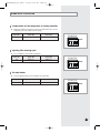
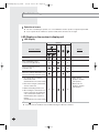
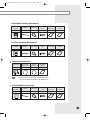
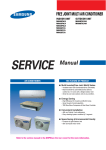
$(':-?)-?%/? !- 0AGE #FLWUVKPI#KT(NQY
'52
'ZVGTPCN5VCVKE2TGUUWTG5GVVKPIHQT2JCUG%QPVTQN/QVQT
4EPDEPOLD=OA?KJPNKHIKPKNUKQ?=J=@FQOPPDAEJ@KKNQJEPB=JOLAA@@ALAJ@EJCKJPDAEJOP=HH=PEKJ
?KJ@EPEKJ&BPDAATPANJ=HOP=PE?LNAOOQNAEODECDOKPD=PPDA@Q?P>A?KIAOHKJCANKNEBPDAATPANJ=HOP=PE?
LNAOOQNAEOHKSOKPD=PPDA@Q?P>A?KIAOODKNPAN=@FQOPPDAB=JOLAA@>UNABANNEJCPDABKHHKSEJCP=>HA
/ABANPKPDAL=CAPKOAPPDAKLPEKJ?K@A
29.5(1041)
27(953)
24(847)
38(1341)
34(1200)
29.5(1041)
+KPA
TGRTGUGPVU'52
'ZVGTPCN5VCVKE2TGUUWTGTCPIGQHHCEVQT[UGVVKPI
;QWFQPVJCXGVQCFLWUVVJGHCPURGGFUGRCTCVGN[KHVJGGZVGTPCNUVCVKERTGUUWTGQHVJGKPUVCNNCVKQP
RNCEGKUKP9JGPKVKUQWVQHKPRWVVJGCRRTQRTKCVGQRVKQPEQFG
+H[QWKPRWVVJGKPCRRTQRTKCVGQRVKQPEQFGGTTQTOC[QEEWTQTVJGCKTEQPFKVKQPGTKUQWV
QHQTFGT6JGQRVKQPEQFGOWUVDGKPRWVVGFEQTTGEVN[D[VJGKPUVCNNCVKQPURGEKCNKUVQT
UGTXKEGCIGPV
4CPIGQHUVCVKERTGUUWTG
(CEVQT[RTGUGV
/QFGN
&*'#/%
&*'#/%
+KPA
'
/KP
'ZVGTPCNUVCVKERTGUUWG
OO#S
0QTOCN
/CZ
(QT&*'#/%[QWECPCFLWUVVJGHCPURGGFD[KPRWVVJGCRRTQRTKCVGQRVKQPEQFG
VQKPETGCUGVJGOCZUVCVKERTGUUWTGWRVQOO#S
DH140GZM_IM_E/O_25844
3/3/06 10:24 AM
Page 25
Setting Up the Mode Option
Setting Option Setup Method
For example) Option Code :
1
Prepare of the Option Setup mode.
a. Take out the batteries of remote control.
b. Press the
button simultaneously and insert the battery again.
c. Make sure the remote control display shows as
2
.
Enter the Option Setup mode and select your option according to the
following procedure.
1 The default value is
. Otherwise, push the
button to
.
1
2
◆ Every time you press the button, the display panel reads or
3
repeatedly.
4
2 Press the
button to set the display panel to
.
5
◆ Every time you press the button, the display panel reads
...
3 Press the
6
repeatedly.
button to set the display panel to
.
◆ Every time you press the button, the display panel reads
...
4 Press the
repeatedly.
button to set the display panel to .
◆ Every time you press the button, the display panel reads
...
5 Press the
❊ Setting is not required if you want to input
. is displayed by default.
repeatedly.
button to set the display panel to .
◆ Every time you press the button, the display panel reads
...
6 Press the
repeatedly.
button to set the display panel to
.
◆ Every time you press the button, the display panel reads
...
repeatedly.
E-25
DH140GZM_IM_E/O_25844
3/3/06 10:25 AM
Page 26
Setting Up the Mode Option (Continued)
7 Press the
button, then the default value is
8 Press the
button to set the display panel to
.
7
8
9
.
◆ Every time you press the button, the display panel reads
...
10
11
9 Press the
12
repeatedly.
button to set the display panel to
.
◆ Every time you press the button, the display panel reads
...
10 Press the
repeatedly.
button to set the display panel to .
◆ Every time you press the button, the display panel reads
...
❊ Setting is not required if you want to input
. is displayed by default.
11 Press the
repeatedly.
button to set the display panel to
.
◆ Every time you press the button, the display panel reads
...
12 Press the
repeatedly.
button to set the display panel to
.
◆ Every time you press the button, the display panel reads
...
3
repeatedly.
Check you made right selections upon completion of the selection.
a. Press the
you inputted.
button once to check the former part of option code
◆ The display part shows
.
b. Press the
button once more to check the latter part of option
code you inputted
◆ The display part shows
E-26
.
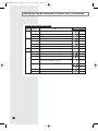
$(':-?)-?%/? !- 0AGE 2TGUUVJGDWVVQP
9JGP[QWRTGUUVJGDWVVQPVQYCTFUVJGKPFQQTWPKV
VJGUQWPF&KPIQT&KTKTKPIKUJGCTFCPFVJGRQYGTKPFKECVQTQHVJG
FKURNC[HNCUJGUCVVJGUCOGVKOG6JGPVJGQRVKQPEQFGUGVVKPIKU
EQORNGVGF
+HVJGUQWPFKUPQVJGCTFRTGUUVJGDWVVQPCICKP
%JGEMVJGCKTEQPFKVKQPGTQRGTCVGUPQTOCNN[
C4GOQXGVJGDCVVGT[HTQOVJGTGOQVGEQPVTQN
D+PUGTVVJGDCVVGT[KPVQVJGTGOQVGEQPVTQNCICKP
E2TGUUVJGVQYCTFUVJGKPFQQTWPKV
+KPA
+HCNNKPFKECVQTUQHVJGKPFQQTWPKVCTGHNCUJKPIRNWIQWVVJGRQYGTRNWI
CPFRNWIKVKPCICKP6JGPRTGUUVJGDWVVQP
+HVJGCKTEQPFKVKQPGTFQGUPQVQRGTCVGPQTOCNN[QTCNNNCORUKPFKECVQTU
HNCUJEJGEMVJCVVJGEQTTGEVQRVKQPEQFGKUUGVWR
1RVKQPKVGOU
/QFGN
4GOQVG
%QPVTQN 5') 5') 5') 5') 5') 5') 5') 5') 5') 5') 5') 5')
&*'#/%
&*'#/%
'
DH140GZM_IM_E/O_25844
3/3/06 10:25 AM
Page 28
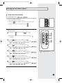
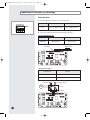
Assigning Address to Indoor Unit
1
Before installing the indoor unit, assign an address to the indoor unit
according to the air conditioning system plan.
2
The address of the indoor unit is assigned by adjusting MAIN(SW02) and
RMC(SW04) rotary switches.
SW02
SW05
SW06 SW07
SW04
SW02
E-28
SW04
K1 K2 K3 K4
K5 K6 K7 K8
K9 K10 K11 K12
SW05
SW06
SW07
3
It is required to set the RMC address if you install the wired remote controller
and/or the centralized controller.
4
If you install optional accessories such as the wired remote controller, centralized
controller, etc. see an appropriate installation manual.
5
If an optional accessory is not installed, you do not have to set the RMC
address. However, adjust K1 and K2 switches of the SW05 DIP switch to "ON"
position in this case.
DH140GZM_IM_E/O_25844
3/3/06 10:25 AM
Page 29
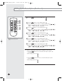
Additional Functions
Compensation for lost temperature in heating operation
◆ Reduces the difference between an actual room temperature and a sensed
temperature by the air conditioner when heating.
Switch No.
Switch ON
Switch OFF
K5
2°C compensation
5°C compensation
K5 K6 K7 K8
SW06
Adjusting filter cleaning cycle
◆ You can adjust the cycle for filter sign indicator.
Switch No.
Switch ON
Switch OFF
K6
1000 hours
2000 hours
K5 K6 K7 K8
SW06
Hot water heater
◆ You must adjust the K7 when you install the hot water heater.
Switch No.
Switch ON
Switch OFF
K7
No use of hot water heater
Use of hot water heater
K5 K6 K7 K8
SW06
E-29
DH140GZM_IM_E/O_25844
3/3/06 10:25 AM
Page 30
Additional Functions (Continued)
External Control
◆ You must adjust the K11 when you use external control.
K 9 K10 K11 K12
SW07
Switch No.
Switch ON
Switch OFF
K11
No use of external control
Use of external control
◆ You can use external control when the K11 switch is turned off.
Operation ON/OFF Function
Connector No.
SHORT
OPEN
CN83(RED)
Operation ON
Operation OFF
ON/OFF Switch
CN83(RED)
Operation State Display
Function
Connector No.
PIN #1 and #2 of CN81(RED)
+12V Out if any error occurs
PIN #3 and #4 of CN81(RED)
+12V Out when the compressor is operating
Error Display
AC
220V
Comp. Status Display
Sub. PCB
CN81(RED)
E-30
DH140GZM_IM_E/O_25844
3/3/06 10:25 AM
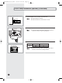
Page 31
Drain Pump Installation (Optional)
Accessories
Drain Pump and Float
Switch(1)
M4 X 12 Tapped
Screw (4)
Cable-Tie (3)
Insulation Drain (2)
Drain Hose (1)
1
Remove the air filter.
2
Assemble the drain socket as seen in the picture after removing the rubber
cap.
Drain socket
3
Assemble the float switch with the drain pump.
Drain pump and
float switch
4
Connect the drain hose.
Drain hose
Note
Attach the drain hose tightly with the cable tie or a bonding
agent so that it does not get removed or water does not drain.
E-31
DH140GZM_IM_E/O_25844
3/3/06 10:25 AM
Page 32
Drain Pump Installation (optional) (Continued)
Must fit tightly against body without any gap.
5
Drain hose
◆ Check if water does not drain.
◆ Insulate the drain hose so that frost does not form.
Note
Cable-tie
Indoor unit
Insert the flexible hose into the drain socket until it clicks.
Insulation
6
Float switch
Connect the cable to the electrical component box as shown at the figure.
◆ Connect the drain pump cable to yellow terminal(CN74)
and the float switch to black terminal(CN51).
Note
Drain pump
7
Adjust K4 DIP switch(SW05) to the "OFF" position.
Switch No.
Switch Position
Using Drain Pump
K4
ON
OFF
X
O
K1 K2 K3 K4
SW05
Note
E-32
◆ Wrap the drain tube outlet on the right and left side of
the indoor unit with an insulating materials.
DH140GZM_IM_E/O_25844
3/3/06 10:25 AM
Page 33
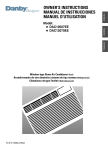
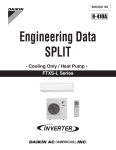
Setting Up Option Switches (Outdoor unit)
❊ Except for cooling only models (The outdoor unit PCB is not applied to the cooling only models)
PCB
Display
Rotary switch
KEY
Rotary Switch
You should display that how many indoor units are connected to
the outdoor unit. Refer to the table below, then turn the arrow to
appropriate position.
Switch No.
Number of
indoor unit(s)
Switch No.
Number of
indoor unit(s)
0 or 1
2
One
9
Nine
Two
A
Ten
3
Three
B
Eleven
4
Four
C
Twelve
5
Five
D
Thirteen
6
Six
E
Fourteen
7
Seven
F
Fifteen
8
Eight
-
-
K1
K2
DIS 1
K4
K3
KEY
DIS 2
Display
CHECK
MODE
RESET
DISPLAY
MODE
ITEM NO.
CURRENT DATA DISPLAY
Summary of KEY functions
Number of
press times
Function
K1
K2
K3
K4
(Displayed on SEG 3, 4) (Displayed on SEG 3, 4) (Displayed on SEG 3, 4) (Displayed on SEG 3, 4)
1
Adding refrigerant at
heating mode
Adding refrigerant at
cooling mode
Reset
Displays data
2
Test operation at
heating mode
Test operation at
cooling mode
-
-
3
End
Pump Down for recovery
of refrigerant
-
-
4
-
End
-
-
❊ Use the K1 only for heat pump models.
E-33
DH140GZM_IM_E/O_25844
3/3/06 10:25 AM
Page 34
Setting up Option Switches (Outdoor unit) (Continued)
Reading data indicated on the display
KEY
Number of
press
K1
1
Adding refrigerant for heat pump models
2
Test operation for heat pump models
3
End
1
Adding refrigerant for cooling only models
2
Test operation for cooling only models
3
Pump Down for recovery of refrigerant
4
End
K2
K3
K4
Item
Example
Display Meaning
Reset
1
Discharge temperature of compressor
2
Temperature of outdoor heat exchanger
38 °C
3
Outdoor temperature
34 °C
4
Step of electronic expansion valve
(0 step : all closed, 480 step : all open)
5
Temperature of evaporator
110 °C
120STEP
(12 x 10)
-2 °C
12 °C
E-34
6
Indoor temperature
7
Stopping view mode & display communication data
22 °C
DH140GZM_IM_E/O_25844
3/3/06 10:25 AM
Page 35
Testing Operations
1
Check the power supply between the outdoor unit and the auxiliary circuit
breaker.
◆ Single phase power supply: L, N
◆ Three phase power supply: L1, L2, L3
2
Check the indoor unit.
◆ Check that you have connected the power and communication
cables correctly. (If the power cable and communication cables
one mixed up or connected incorrectly, the PCB will be damaged.)
3
If the outdoor unit is powered on, it will start tracking to check user's
option(s) and number of indoor unit.
- At this time, the SEG 1 and SEG 2 on outdoor unit PCB display the
number of indoor unit registered and the SEG 3 and SEG 4 display
the number of indoor units which responded.
- If an error mode is displayed, fix the error according to the service
manual.
4
Press K2 on the outdoor unit PCB.
- If you press K2, the compressor starts operation.
Operate the compressor for 20 minutes, then add refrigerant according
to the pipe length.
- If you press K2 again, test operation is started.
- If you don't stop the operation of adding refrigerant, it will be stopped
automatically after 1 hour.
- If you don't stop test operation, it will be stopped automatically
after 1 hour.
- If K2 is pressed during the operation of adding refrigerant, test operation
is started without compressor stopping. Therefore, start test operation
after the operation of adding refrigerant.
- The compressor can be operated after completely 3-minute preparation
and tracking.
- When testing operations at Heating Mode, press K1 instead of K2.
5
Check that indoor and outdoor temperatures, step of electronic expansion
valve and operation of compressor by using the display mode(K4).
6
Check that there is any error mode in the outdoor unit PCB during the test.
- You should test operations for more than 30 minutes.
- Check that the water dripping from the drain hose runs away correctly
and safely.
7
To complete the test, press the test operation KEY(K2) again.
E-35
DH140GZM_IM_E/O_25844
3/3/06 10:25 AM
Page 36
Troubleshooting
Detection of errors
◆ If an error occurs during the operation, one or more LED flickers and the operation is stopped except the LED.
◆ If you re-operate the air conditioner, it operates normally at first, then detect an error again.
LED Display on the receiver & display unit
LED Display
Indicators
Concealed Type
Abnormal conditions
Blue
Remarks
Red
Standard Type
X
X
X
X
X
X
Error of heat exchanger sensor
in the indoor unit
X
X
X
Error of the outdoor temperature sensor
Error of the condensor temperature sensor
Error of the discharge temperature sensor
X
Power reset
Error of temperature sensor
in the indoor unitt (Open/Short)
X
X
X
X
1. No communication for 2 minutes
between indoor units
1. Indoor unit error
(Display is unrelated
with operation)
(Communication error for more than 2 minutes)
2. Outdoor unit error
(Display is unrelated
with operation)
2. Indoor unit receiving the communication
error from outdoor unit
3. Outdoor unit tracking 3 minutes error
X
X
X
4. When sending the communication error
from the outdoor unit, the mismatching
of the communication numbers and
installed numbers after completion of
tracking
(Communication error for more than 2 minutes)
● On
Flickering
X Off
◆ If you turn off the air conditioner when the LED is flickering, the LED is also turned off.
E-36
DH140GZM_IM_E/O_25844
3/3/06 10:25 AM
Page 37
LED Display
Indicators
Concealed Type
Abnormal conditions
Blue
Remarks
Red
Standard Type
Communication error between indoor units
X
X
X
1. Error of electronic expansion valve close
2. Error of electronic expansion valve open
3. 2’nd detection of high temperature cond
4. 2’nd detection of high temperature
discharge
X
X
Detection of the float switch
X
X
Error of setting option switches for optional
accessories
X
X
5. Error of reverse phase
6. Compressor down due to 6’th detection
of freezing
EEPROM error
X
X
X
EEPROM option error
● On
Flickering
X Off
◆ If you turn off the air conditioner when the LED is flickering, the LED is also turned off.
E-37
DH140GZM_IM_E/O_25844
3/3/06 10:25 AM
Page 38
Troubleshooting (Continued)
Wired remote controller
◆ If an error occurs,
is displayed on the wired remote controller.
◆ If you would like to see an error code, press the Test button.
Display
Explanation
Compressor down due to protection control of the discharge
temperature sensor
Remark
Error about protection
control of the outdoor unit
Control due to the condenser temperature sensor when cooling
mode
Error of the low pressure switch (Protection control)
Reverse phase error (Protection control)
In removing frost
Error of discharge temperature sensor (Open/Short)
Error about the outdoor unit
sensor (Open/Short)
Detection during the
operation of the indoor unit
(sensing and sending errors
into the communication data)
- System down caused by communication error after completion
of tracking
Communication and the
indoor unit errors
Error of the outdoor temperature sensor (Open/Short)
Error of condensor temperature sensor (Open/Short)
- Mismatching of the indoor unit numbers set with those
communication after completion of 5 times tracking
Error of temperature sensor in the indoor unit (Open/Short)
Self-diagnosis of the
indoor and outdoor unit
Error of the heat exchanger sensor in the indoor unit (Open/Short)
Error of electronic expansion valve open in the outdoor unit
(when it is detected more than once)
Error of electronic expansion valve close in the outdoor unit
(when it is detected more than once)
Error of communication between the indoor unit and the wired
remote controller
Master wired remote controller ↔ Slave wired remote controller
COM1/COM2 Cross-installed error
Error of setting option for wired remote controller COM2
E-38
Wired remote controller
errors
DH140GZM_IM_E/O_25844
3/3/06 10:25 AM
Page 39
Outdoor unit
If an error occurs during the operation, it is displayed on the outdoor unit PCB.
Display
Explanation
High temperature of Discharge (Protection control)
High temperature of outdoor heat exchanger (Protection control)
Remark
Error about protection
control of outdoor unit
Reverse phase error (Protection control)
COMP DOWN to protect being frozen
In removing frost
Error of Discharge TEMP sensor (OPEN/SHORT)
Errors about outdoor unit
sensor (OPEN/SHORT)
Detection during the
operation of indoor unit
(Sensing and sending errors
into the communication data)
System Down caused by communication error after
completion of tracking
Communication and indoor
unit errors
Error of OUT TEMP sensor (OPEN/SHORT)
Error of temperature sensor in outdoor heat exchanger (OPEN/SHORT)
Mismatching of the indoor unit numbers set with those
communicated after completion of tracking
Error of float switch in indoor unit
Error of setting option switches for optional accessories
x
OPEN/SHORT error of room sensor in indoor unit
x
OPEN/SHORT error of eva in sensor in indoor unit
x
EEPROM option error
x
Error of fan starting
Self-diagnosis of indoor
and outdoor unit (x:indoor
unit address)
Displays of operating status
Open error of electronic expansion valve in outdoor unit
(Detected once or more times)
Close error of electronic expansion valve in outdoor unit
(Detected once or more times)
Flicker
Below -5°C when cooling (Outdoor temperature)
Flicker
Over 30°C when heating (Outdoor temperature)
K1, K2, K3, K4,
K5 Flicker
The order of priority : E1 → E2 → E5 → P0 → P1 → P4 → P5 → P9 → t1 → t2 → t3 → tu → to →
G4 → G5 → E3 → qx → rx → vx → K1, K2, K3, K4, K5
- In case that the same error displays from multi-indoor units, the one having the faster
address has the priority.
E-39
DH140GZM_IM_E/O_25844
3/3/06 10:25 AM
Page 40
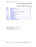
Parts List
Receiver & Display Unit Accessories
Concealed Type
◆ Receiver & display unit
Receiver &
display unit
1
◆ Wire kit
STS 2S-2x10
2S-4x12
tapped screw tapped screw
4
2
Owner’s
instructions
Installation
manual
Wire kit
1
1
1
Standard Type
◆ Wire kit
◆ Receiver & display unit
Receiver &
display unit
M4x16 tapped
screw
Cable-tie
Cable clamp
Owner’s
instructions
Installation
manual
Wire kit
1
7
2
5
1
1
1
Owner’s
instructions
Installation
manual
1
1
Wireless Remote Controller Accessories
E-40
Wireless
remote controller
Battery
1
2
Remote control STS 2S-2x10
holder
tapped screw
1
2
DH140GZM_IM_E/O_25844
3/3/06 10:25 AM
Page 41
Centralized Controller Accessories
Centralized
controller
Cable-tie
Cable clamp
M4x16 tapped
screw
Owner’s
instructions
Installation
manual
1
2
5
7
1
1
Function Controller Accessories
Function
controller
Cable-tie
Cable clamp
M4x16 tapped
screw
Owner’s
instructions
Installation
manual
1
2
6
7
1
1
Transmitter Accessories
Transmitter
Transmitter
power cable
Transmitter
communication cable
Installation
manual
1
1
1
1
◆ If you would like to install the centralized controller,
Note
you must install the transmitter in the outdoor unit.
7-day Scheduler Accessories
7-day
Scheduler
Cable-tie
Cable clamp
M4x16 tapped
screw
Owner’s
instructions
Installation
manual
1
2
2
4
1
1
E-41
&$#A'KPFF