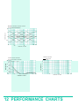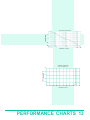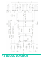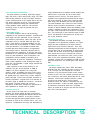
1
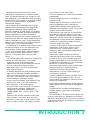
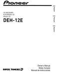
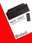
IMPORTANT SAFETY INSTRUCTIONS
THESE INSTRUCTIONS ARE TO
PROTECT YOU AND THE MclNTOSH
INSTRUMENT. BE SURE TO
FAMILIARIZE YOURSELF WITH THEM.
1. Read all instructions - Read the safety and
operating instructions before operating the
instrument.
2. Retain Instructions - Retain the safety and
operating instructions for future reference.
3. Heed warnings - Adhere to warnings and
operating instructions.
4. Follow Instructions - Follow all operating and use
instructions.
WARNING: TO REDUCE RISK OF FIRE OR
ELECTRICAL SHOCK, DO NOT EXPOSE THIS
INSTRUMENT TO RAIN OR MOISTURE.
5. Power Sources - Connect the power supply only to
the type described in the operating instructions or
as marked on the unit.
6. Power-Cord Protection - Route power-supply cords
so that they are not likely to be walked on or
pinched by items placed upon or against them,
paying particular attention to cords at plugs,
convenience receptacles, and the point where they
exit from the instrument.
7. Ventilation - Locate the instrument for proper
ventilation. For example, the instrument should
not be placed on a bed, sofa, rug, or similar
surface that may block ventilation openings; or,
placed in a built-in installation, such as a bookcase
or cabinet, that may impede the flow of air
through the ventilation openings.
8. Heat - Locate the instrument away from heat
sources such as radiators, heat registers, stoves, or
other appliance (including amplifiers) that produce
heat.
9. Wall or Cabinet Mounting - Mount the instrument
in a wall or cabinet only as described in the
owners manual.
10. Water and Moisture - Do not use the instrument
near water - for example, near a bathtub,
washbowl, kitchen sink, laundry tub, in a wet
basement, or near a swimming pool, etc.
11. Cleaning - Clean the instrument by dusting with a
dry cloth. Clean the panel with a cloth moistened
with a window cleaner.
12. Object and Liquid Entry - Do not permit objects to
fall and liquids to spill into the instrument through
enclosure openings.
13. Power Lines - Locate any outdoor antenna away
from power lines.
14. Outdoor Antenna Grounding - If an outdoor
antenna is connected to the antenna terminal, be
sure the antenna system is grounded to provide
some protection against voltage surges and built
up static charge.
In the U.S.A., section 810 of the National Electrical
Code, ANSI/NFPA No. 70-1987, provides
information on the proper ground for the mast
and supporting structure, ground for the lead-in
wire to an antenna discharge unit, and size of
ground conductors, location of antenna-discharge
unit, connection to grounding electrodes, and
requirements for the grounding electrode.
For ground wire:
a) Use No. 10 AWG (5.3 mm2) copper No. 8 AWG
(8.4 mm2) aluminum, No. 17 AWG (1.0 mm2)
copper-clad steel, bronze wire, or larger as ground
wire.
b) Secure antenna lead-in and ground wires to
house with stand-off insulators spaced from 4 feet
(1.22 meters) to 6 feet (1.83 meters) apart.
c) Mount antenna discharge unit as closely as
possible to where lead-in enters house,
d) Use jumper wire not smaller than No. 6 AWG
(13.3 mm2) copper or equivalent when separate
antenna grounding electrode is used.
15. Nonuse Periods - Unplug the power cord from the
AC power outlet when left unused for a long
period of time.
16. Damage Requiring Service - Service must be
performed by qualified service personnel when:
A. The power supply cord or the plug has been
damaged; or
B. Objects have fallen, or liquid has been spilled
into the instrument; or
C. The instrument has been exposed to rain; or
D. The instrument does not appear to operate
normally or exhibits a marked change in
performance; or
E. The instrument has been dropped, or the
enclosure damaged.
17. Servicing - Do not attempt to service beyond that
described in the operating instructions. All other
service should be referred to qualified service
personnel.
18. Grounding or Polarization - Do not defeat the
inherent design features of the polarized plug.
Non-polarized line cord adaptors will defeat the
safety provided by the polarized AC plug.
The lightning flash with arrowhead, within an
equilateral triangle, is intended to alert the user to
the presence of uninsulated "dangerous voltage"
within the product's enclosure that may be of
sufficient magnitude to constitute a risk of electric
shock to persons.
19. CAUTION: TO PREVENT ELECTICAL SHOCK DO
NOT USE THIS (POLARIZED) PLUG WITH AN
EXTENSION CORD, RECEPTACLE OR OTHER
OUTLET UNLESS THE BLADES CAN BE FULLY
INSERTED TO PREVENT BLADE EXPOSURE.
Note to CATV system installer:
This reminder is provided to call the CATV system
installer's attention to Article 820-22 of the NEC
that provides guidelines for proper grounding
and, in particular, specifies that the cable ground
shall be connected to the grounding system of
the building, as close to the point of cable entry
as practical.
ATTENTION: POUR PREVENIR LES CHOCS
ELECTRIQUES PAS UTILISER CETTE FICHE
POLARISEE AVEC UN PROLONGATEUR, UNE PRISE
DE COURANT OU UNE AUTRE SORTIE DE
COURANT, SAUF SI LES LAMES PEUVENT ETRE
INSEREES A FOND SANS EN LAISSER AUCUNE
PARTIE A DECOUVERT.
The serial number, purchase date, and Mclntosh
Laboratory Service Contract number are important to
you for possible insurance claim or future service.
Record this information here.
Serial Number
Purchase Date
CAUTION: TO PREVENT THE RISK OF ELECTRIC
SHOCK, DO NOT REMOVE COVER (OR BACK). NO
USER-SERVICABLE PARTS INSIDE. REFER SERVICING
TO QUALIFIED PERSONNEL.
The exclamation point within an equilateral triangle
is intended to alert the user to the presence of
important operating and maintenance (servicing)
instructions in the literature accompanying the
appliance.
Service Contract Number
Upon application, Mclntosh Laboratory
provides a Service Contract to the original
purchaser. Your Mclntosh Authorized
Service Agency can expedite repairs when
you provide the Service Contract with the
instrument for repair.
1
Contents
INTRODUCTION
INSTALLATION
HOW TO CONNECT
FRONT PANEL CONTROLS
PERFORMANCE LIMITS
PERFORMANCE CHARTS
BLOCK DIAGRAM
TECHNICAL DESCRIPTION
CONNECTING DIAGRAM
3
4, 5
6, 7, 8
9, 10
11
12, 13
14
15
16
Your C35 System Control Center will give you many
years of satisfactory performance. If you have any
questions, please contact,
CUSTOMER SERVICE
Mclntosh Laboratory Inc.
2 Chambers Street
Binghamton, New York 13903-2699
Phone: 607-723-3512
Take Advantage of 3 Years of
Contract Service. . .
Fill in the Application NOW.
MclNTOSH THREE YEAR SERVICE CONTRACT
An application for A THREE YEAR SERVICE CONTRACT is included with this manual.
The terms of the contract are:
1. If the instrument covered by this contract
becomes defective, Mclntosh will provide all parts,
materials, and labor needed to return the
measured performance of the instrument to the
original performance limits free of any charge. The
service contract does not cover any shipping costs
to and from the authorized service agency or the
factory.
2. Any Mclntosh authorized service agency will
repair all Mclntosh instruments at normal service
rates. To receive the free service under the terms
of the service contract, the service contract
certificate must accompany the instrument when
taken to the service agency.
3. Always have service done by a Mclntosh
authorized service agency. If the instrument is
2
modified or damaged as a result of unauthorized
repair the service contract will be cancelled.
Damage by improper use or mishandling is not
covered by the service contract.
4. The service contract is issued to you as the
original purchaser. To protect you from
misrepresentation this contract cannot be
transferred to a second owner.
5. Units in operation outside the United States and
Canada are not covered by the Mclntosh Factory
Service Contract, irrespective of the place of
purchase. Nor are units acquired outside the USA
and Canada, the purchasers of which should
consult with their dealer to ascertain what, if any,
service contract or warranty may be available
locally.
Mclntosh has earned world renown for its
technological contributions for improved sound.
When you bought Mclntosh, you bought not only
high technology, you bought technological integrity
proven by time. The Mclntosh C 35 System Control
Center is the newest evidence of Mclntosh
technological integrity.
Music reproducing instruments that carry the
Mclntosh name have always been designed for
technological leadership and to maintain the
Mclntosh reputation for best sound, for durability,
and for long life. Mclntosh has always earned the
foremost reputation for quality performance.
Mclntosh has provided user oriented facilities and
appearance and Mclntosh design always provides for
ease of maintenance or repair. These fundamental
elements are incorporated in the Mclntosh System
Control Center, yet it is easy to operate.
Your Mclntosh C 35 System Control Center, above
all others will deliver to you the best sound, the
most flexibility, and the greatest ease of use.
The C 35 is a superb quality, high performance
System Control Center. With the MVS-1 Video
Selector, it will provide both audio and video
control.
The C 35 has many useful features to enhance your
listening and video enjoyment. They include:
High level inputs to accommodate the
traditional as well as all the latest audio sources
such as compact disc players and the
high-quality audio from video recorders and
laser video disc players.
A specially designed low noise switching system
uses a pair of cascaded field effect transistors
(FET) to operate the inputs. The input leads are
very short, one-twentieth (1/20) of the length of
previous designs. Advantages include,
source-to-source isolation, lower distortion, and
freedom from hum, noise, and interference
from high-power TV and radar signals.
Any one of nine input sources can be selected
using electronic switching. These inputs
identified as Compact Disc, LASER disc, TV,
TUNER, PHONO, AUX 1, AUX 2, VCR/T1, and
VCR/T2.
Electronic tape monitor switches for two audio
tape recorders, or the audio from two video
recorders, or one audio recorder and the audio
from one video recorder, allow either recorder
to be heard from the main output.
Volume is adjusted by a motor driven precision
potentiometer.
Left/right tracking accuracy is controlled to a
fraction of a dB.
SPEAKER buttons select both or either of two
sets of loudspeakers (when used with the
optional SCR 3 speaker control relay) or two
additional power amplifiers, which can provide
program to other listening areas.
These facilities and more may be selected and
controlled by either the buttons on the front
panel or the hand-held infrared remote control.
Additionally, remote control can be extended to
two additional listening areas by the installation
of Mclntosh remote sensors which are easily
connected by RG-59/U cable.
An active circuit loudness control is electrically
independent of the volume control. Close
conformity to the Fletcher-Munson equal
loudness curves can be attained regardless of
the volume setting.
A five-band program equalizer permits the
adjustment and improvement of the loudness
contrast of the five most important frequency
ranges. Musical balance of source material can
be adjusted to compensate for room recording
differences or listener preferences.
Rear panel signal switching jacks provide output
and input facilities for signal processing
equipment. Processors may be used
independently to modify a tape recording or
the listened-to program.
A built-in headphone amplifier provides power
to the front panel headphone jack. All front
panel controls are available to influence private
listening on headphones.
Electronically regulated power supplies maintain
stable operation during periods of changing line
voltage.
Professional XLR connectors provide balanced
optimum signal to noise ratio in demanding
applications.
This outstanding C 35 System Control Center will
serve you best when you understand its functions
and what it is designed to do. Some time invested in
reading this manual will be valuable in obtaining the
most from your C 35.
INTRODUCTION 3
The trouble-free life of an electronic instrument is
greatly extended by providing sufficient ventilation to
prevent the build-up of high internal temperatures
that cause deterioration. Allow enough clearance so
that cool air can enter at the bottom of the cabinet
and be vented from the top. With adequate
ventilation the instrument can be mounted in any
position. The recommended minimum space for
installation is 15 inches (38.1 cm) deep, 17 inches
(43.2 cm) wide, and 6 inches (15.2 cm) high.
The C 35 may be installed in a Mclntosh cabinet or
custom installed in furniture of your choice. Always
provide adequate ventilation, Never place it above
heat generating components such as high powered
amplifiers. Provide 1½ inches (3 cm) of space above
the preamplifier so as not to interfere with a cooling
air flow.
CUSTOM INSTALLATION
The PANLOC system of installing equipment
conveniently and securely is a product of Mclntosh
research. The PANLOC buttons on the front pane!
will lock the unit firmly in place when they are
turned approximately one quarter turn clockwise. A
counterclockwise turn of the PANLOC buttons
unlocks the chassis from its mounting.
To install the instrument in a Mclntosh cabinet,
follow the instructions that are enclosed with the
cabinet. For any other type of installation, follow
these instructions:
the instrument from its plastic bag and place it
upside down on the shipping pallet. Unscrew the
four plastic feet from the bottom of the chassis.
2. Mark the Cabinet Panel
Tape the mounting template in position on the
cabinet panel where the instrument is to be
installed. The broken lines that represent the outline
of the rectangular cutout also represent the outside
dimensions of the chassis. Make sure these lines
clear shelves, partitions, or any equipment. With the
template in place, first mark the six A and B holes
and the four small holes that locate the corners of
the cutout. Then, join the four corner markings with
pencil lines, using the edge of the template as a
straightedge.
3. Drill Holes
Use a drill with a 3/16 inch (5 mm) bit held
perpendicular to the panel and drill the six A and B
holes. Then, using a drill bit slightly larger than the
tip of your saw blade, drill one hole at each of two
diagonally opposite corners. The holes should barely
touch the inside edge of the penciled outline. Before
taking the next step, make sure that the six A and B
holes have been drilled.
1. Unpack from Carton
Open the carton and remove the PANLOC brackets,
hardware package, and mounting template. Remove
4 INSTALLATION
4. Saw the Panel Cutout
Saw carefully on the inside of the penciled lines,
First make the two long cuts and then the two short
cuts. After the rectangular opening has been cut out,
use a file to square the corners and smooth any
irregularities in the cut edges.
5. Install the Mounting Strips
In the hardware package are two mounting strips,
and two 1-1/4" (31.8mm) black long screws that have
a flat head. Use these screws, one on each end, to
fasten the mounting strips. They are attached
through the center hole, marked B on the template.
Make sure the screw heads are drawn flush or
slightly into the wood before attaching the Panloc
brackets.
6. Attach the PANLOC Brackets
In the hardware package are two sets of screws. For
panels less than 1/2" (12.7mm) thick, use the 3/4"
(19.1mm) long screws; for thicker panels, use the
1-1/4" (31.8mm) long screws.
Using two screws of the proper length in the A
holes on each side, attach the PANLOC brackets to
the cabinet panel; the short flange is mounted
against the front (face) of the cabinet panel. The
screws pass through the PANLOC bracket flange, the
cabinet panel, and then through the mounting strips
previously mounted.
7. Install the Instrument
Guide the AC power cord through the panel opening
to the back of the cabinet; then, slide the instrument
into the opening carefully so that the rails on the
bottom of each side of the chassis engage the tracks
on the mounting brackets. Continue to slide the
instrument into the cabinet until the front panel is
flush with the cabinet panel. Turn the PANLOC
buttons at the lower left and right corners of the
instrument panel clockwise to lock the unit firmly in
the cabinet. Turn the PANLOC buttons
counterclockwise to unlock the instrument. It can
then slide outward to permit the removal.
INSTALLATION 5
be connected to the TV INPUT. Connect the left
channel cable to the Left TV INPUT. Connect the
right channel cable to Right TV INPUT.
The output of a monophonic TV set can be
connected to both left and right channel TV
INPUTS by use of a "Y" connector.
The back cover of this manual folds out to show
photographs of the front and rear panels of the C 35.
Fold it out to assist you in locating the connectors. The
numbers refer to the paragraphs that follow.
There are four fields of audio connectors on the
back panel of the C 35 for use with associated
equipment: AUDIO INPUTS, EXTERNAL
PROCESSORS, AUDIO OUTPUTS, and BALANCED
OUTPUTS. On the front panel is an additional phone
jack for use with headphones.
Use shielded cables to interconnect the source
equipment and the preamplifier. To minimize the
possibility of hum or noise, the shielded cables
should be of parallel construction or, if not, loosely
twist the left and right cables together. Locate them
away from the speaker connecting cables and AC
power cords. Be certain to use good quality shielded
cables for all interconnections. Your dealer can
advise you on the kind and length of cable that will
best suit your installation.
The first field of connectors is marked:
AUDIO INPUTS
1.
PHONO:
Connect the cable from the turntable left
channel to the Left Phono INPUT. Connect the
cable from the turntable right channel to the Right
PHono INPUT. If the turntable has a separate
ground lead, connect it to the screw terminal
marked ground (GND).
2. GND (ground):
The ground (GND) post on the rear panel is
provided primarily for grounding a turntable or
record changer that has a separate ground lead in
addition to the signal leads.
3. CD:
Connect the cable from the Compact Disc (CD)
player left channel output to the Left CD INPUT.
Connect the cable from the CD player right
channel output to the Right CD INPUT.
4. LASER VISION PLAYER:
The audio from a laser vision video disc player
can be connected to the LASER INPUT. Connect
the cable from the left channel audio output of a
laser disc player to the Left LASER INPUT. Connect
the cable from the right channel audio output of a
laser disc player to the Right LASER INPUT.
5. TV:
Audio from a stereo TV set or TV monitor can
6.
TUNER:
Connect the cable from the tuner left channel
output to the Left TUNER INPUT. Connect the
cable from the tuner right channel output to the
Right TUNER INPUT.
7. AUX 1 AND 2:
Audio from any high level source is connected
to AUX 1 or 2 INPUTS. Connect a cable from the
left channel audio output of a TV monitor or other
high level source, to the Left AUX 1 INPUT jack.
Connect a cable from the right channel audio
output to the Right AUX 1 INPUT jack. AUX 2 may
be used in a similar manner.
8.
VCR 1/TAPE 1:
For tape playback or to monitor while recording:
connect a cable from the tape recorder left channel output to the Left VCR 1/TAPE 1 INPUT. Connect a cable from the tape recorder right channel
output to the Right VCR 1/TAPE 1 INPUT. Connect
a second recorder in the same manner to the VCR
2/TAPE 2 INPUT.
Video Tape Recorders: If you prefer, one or both
of the VCR/TAPE INPUTS can be used for the
audio from a VCR. Connect the left channel audio
output from the VCR to the Left VCR 1/TAPE 1
INPUT. Connect the right channel audio output
from the VCR to the Right VCR 1/TAPE 1 INPUT. If
the VCR has only a single audio output (mono),
use a "Y" connector to connect the program to
both the left and right input.
The second field of connectors is marked:
EXTERNAL PROCESSORS
9. EXTERNAL PROCESSORS
There are two sets of EXTERNAL PROCESSOR
jacks. The TAPE set affects the program fed to the
VCR/TAPE 1 and 2 OUTPUT jacks and the MAIN
set affects the program fed to the AUDIO OUTPUTS MAIN and SWITCHED 1 and 2 jacks. Use the
EXTERNAL PROCESSOR jacks to add a noise
reduction or any audio signal processing device.
Be sure to match the left to left and right to right
channels when connecting external processors.
The EXTERNAL PROCESSOR-FROM jacks have
6 HOW TO CONNECT
shielded cables with XLR type connectors to connect between the preamplifier and the power
amplifier.
When using 2 conductor shielded cables with
XLR type connectors, connect the BALANCED
OUTPUT LEFT of the preamplifier into the left XLR
connector on the power amplifier. Connect the
BALANCED OUTPUT RIGHT on the preamplifier to
power amplifier right XLR connector.
Pin configuration of the XLR connectors is:
PIN 1: Shield ground
PIN 2: + OUT
PIN 3: - OUT.
switching contacts which allow the signal to pass
through them when nothing is plugged into the
jacks. When an external processor is used, the
program is routed to the external processor from
the EXTERNAL PROCESSOR TO jack and back by
the EXTERNAL PROCESSOR FROM jack.
WHEN AN EXTERNAL PROCESSOR IS USED, IT
MUST BE TURNED ON FOR THE PROGRAM TO BE
HEARD THROUGH THE SYSTEM.
The third and fourth fields of connectors are
marked:
AUDIO OUTPUTS and BALANCED OUTPUTS
10. VCR 1/TAPE 1 and VCR 2/TAPE 2
To record VCR audio or audio tape, connect a
cable from the Left VCR 1/TAPE 1 OUTPUT to the
left high-level input of the recorder. Connect a
cable from the Right VCR I/TAPE 1 OUTPUT to the
right input of the recorder. Connect a second
recorder in the same manner to the VCR 2/TAPE 2
OUTPUT.
11. MAIN:
Connect a cable from the left C 35 MAIN
OUTPUT jack to the left power amplifier input
jack.
Connect a cable from the right MAIN OUTPUT
jack to the right power amplifier input jack.
12. SWITCHED 1 and 2:
Two additional stereo power amplifiers may be
connected to the AUDIO OUTPUT SWITCHED 1
and 2 jacks. Audio output signal is supplied to
these jacks only when the front panel button
SPEAKER 1 and/or 2 buttons are pressed. This
arrangement is useful for systems where separate
amplifiers and loudspeakers are used at remote
locations.
Additional amplifiers can serve remote areas such
as selected living areas, workshop, or outdoor
recreational facilities. Other devices can be
controlled such as a rear channel reverberation unit.
13. BALANCED OUTPUTS
Modern technology has made it possible to
build preamplifiers and power amplifiers with the
high signal-to-noise ratio necessary to reproduce
the sound quality present on compact discs.
Interconnecting cables can pick up electrical
interference from other equipment or applicances.
The balanced outputs on the C 35 provide a
minimum of 40 dB more protection against such
"common mode" noise pick-up. Use 2 conductor
14.
AC POWER:
Plug the preamplifier AC power cord into a 120
volt 60 Hz wall outlet. The plug blades are
polarized so be certain the plug is fully inserted in
the outlet to prevent blade exposure.
CAUTION: TO PREVENT ELECTRIC SHOCK, DO
NOT USE THE (POLARIZED) PLUG ON THIS UNIT
WITH AN EXTENSION CORD, RECEPTACLE, OR
OTHER OUTLET UNLESS THE BLADES CAN BE
FULLY INSERTED TO PREVENT BLADE EXPOSURE.
Two types of AC power outlets are provided on
the back panel of the C 35. One is red, the rest
are black.
The red outlet is on at all times and is used with
accessories that have their own power switches.
For example, a VCR plugged into this outlet will
be able to record TV programs when the main
audio system is turned off.
The black outlets are switched on or off when
the C 35 is turned on or off. Use these to provide
AC power to amplifiers, CD players, or other
accessories. The power capacity of all the outlets,
totalled, is 1500 watts. For power consumption
above 1500 watts, it is necessary to add a
Mclntosh SCR 3 (SPEAKER CONTROL RELAY). The
SCR 3 has two AC power outlets that provide
additional capacity of 1800 watts switched on or
off by the C 35. Use these outlets to supply AC
power to amplifiers or other components
whenever the total load to be switched exceeds
the C 35 rating of 1500 watts.
15. SCR (optional accessory):
The SPEAKER CONTROL RELAY (SCR 3) is
designed to provide both AC outlet switching and
speaker switching.
The SCR 3 has two AC power outlets that
HOW TO CONNECT 7
provide additional capacity of 1800 watts which is
controlled by the AC power switch on the C 35.
Use these outlets to supply AC power to
amplifiers or other components when the total
load switched exceeds the C 35 rating of 1500
watts. Plug the computer-type connector on the
cable attached to the SCR 3 into the SCR socket
on the rear of the C 35. Plug the SCR 3 heavy, AC
power line cord directly into a wall outlet. Do not
plug it into the C 35. When the C 35 is turned on,
a control voltage from the C 35 will energize a
relay in the SCR 3 which connects the two SCR 3
AC power outlets directly to the wall outlet.
Two loudspeakers can be turned on or off with
the SCR 3 by using the C 35 front panel buttons
SPEAKER 1 and 2. Use the SPEAKER 1 terminal
strip on the SCR 3 to connect the main listening
pair of speakers and SPEAKER 2 terminal strip to a
remote area pair of speakers. Connect the power
amplifier output to the POWER AMPLIFIER terminal strip. Maintain left and right orientation and
like polarity. The SPEAKER 1 button will turn the
main speakers on or off and the SPEAKER 2 button
will turn the remote speakers on or off.
16. TUNER:
A multipin computer-type connector is provided
to interconnect the C 35 with Mclntosh tuners
designed for infrared remote control. When so
connected, the HR 35 remote control will operate
the normal functions of the tuner.
With this system you can turn on the tuner,
select from the preprogrammed stations, search
sequentially the programmed stations, or scan the
entire broadcast band on either the AM or FM
band; and raise or lower volume.
17. VIDEO SELECTOR: (optional accessory)
The Mclntosh VIDEO SELECTOR, MVS-1, is
designed to enable the C 35 to control video
programs as well as audio. The MVS-1 connects to
the VIDEO SELECTOR computer-type connector on
the rear of the C 35. Follow the instructions with
the MVS-1 for connecting the video cables.
interference with the main area controlled by the
C 35. Additional independent REMOTE CONTROL
modules and power amplifier, can be added for
each area in which remote control is desired.
19.
CD:
A DIN connector is provided to interconnect the
C 35 with a Mclntosh Compact Disc player. When
so connected, the HR 35 remote control for the
C 35 will operate these functions of the Compact
Disc player:
1) turn the player on or off
2} play a disc
3) move to the next track
4) back up a track
5) raise or lower the volume
6) mute the program.
7) stop the playing of the disc.
20. SENSORS 1 and 2: (optional accessory)
Connectors are provided to add two additional
Mclntosh infrared sensors. This added
convenience permits complete control of the
stereo system from areas remote to the location of
the C 35. Remote sensors are interconnected with
RC-59/U antenna cable.
INSERTING THE BATTERIES IN THE HR 35
REMOTE CONTROL
Your Mclntosh C 35 System Control Center is
complete including Remote Control. In your hand,
you have the ability to control all functions of the
preamplifier with the exception of these controls:
LOUDNESS, BALANCE, VCR/COPY, MONO mode
selection and EQUALIZER. These can only be changed by use of the front panel controls.
The remote control runs on two AA, 1.5 volt
batteries. Slide open the cover on the back of the
remote control and insert the batteries as shown in
the diagram in the battery compartment, then slide
the cover closed again.
Battery life is normally about one year. Remove the
batteries as soon as they are dead to prevent damage
by possible battery leakage or in case the remote
control is not to be used for a length of time.
18. AREA CONTROLLER: (optional accessory)
Adding the optional Mclntosh R624 Remote
Control Interface and the proper Mclntosh
REMOTE CONTROL modules provides independent remote control facilities in additional areas.
In these areas, source can be selected and the
volume adjusted independently of and without
8 HOW TO CONNECT
The back cover of this manual folds out to show
photographs of the front and rear panels of the C 35.
Fold it out to assist you in identifying and locating the
controls on the photographs. The letters refer to the
paragraphs that follow.
The glass upper half of the C 35 front panel is the
message center. It illustrates the source, volume
setting, mode of operation, tape facilities in use, and
connected operating speakers. The infrared sensor
which accepts information from the HR 35 hand-held
remote control is left of the VOLUME indicator.
The black anodized aluminum lower half of the
front panel contains the buttons for:
1) source selection
2) mute
3) audio and video tape selection (video capability
with accessory Mclntosh MVS-1 Video Switcher)
4) stereo or mono mode selection
5) two area speaker switching (with the accessory
SCR 3), and
6} on/off AC power.
The five EQUALIZER FREQUENCY controls,
BALANCE, and LOUDNESS controls have been retained as rotating knobs to provide a high degree of
repeatability. A headphone jack, the VOLUME up
and down
buttons, and PANLOC locking
buttons complete the front panel controls.
A. POWER:
The red button on the C 35 and the POWER button on the remote control turn the AC power on
or off. When turned on, the message center will
display (illuminate) the source that has been
selected, any special operating modes, and the
VOLUME setting.
B. SOURCE:
To listen to a desired source (CD, LASER, TV,
TUNER, PHONO, AUX1 or AUX2, etc), touch either
the front panel button or the corresponding HR 35
remote control button. The indicator in the
message center for that button will light.
C. MUTE:
Should you desire to silence the system briefly,
touch the MUTE button on either the C 35 or the
remote control. A red LED above the MUTE button
will light, and the program will be silenced at the
MAIN and SPEAKER 1 and 2 AUDIO OUTPUTS only.
Touch either button to un-mute. Mute does not affect the tape outputs.
D. MONITOR:
IMPORTANT: When the C 35 is operated in
MONITOR mode with VCR/T1 or VCR/T2 lighted in
the message center, the program heard will be that
from the tape recorders only. Any other source will
not be heard from the loudspeakers.
The C 35 is designed to be used with two tape
recorders, either audio or video, or one audio and
one video recorder.
The MONITOR switches are electronically
interlocked to prevent simultaneous monitoring
from two tape recorders.
The four buttons, MONITOR VCR/T1, VCR/T2,
VCR/T COPY, 1
2,2
1, control the signal in
and out of these recorders. They permit
recordings to be monitored while recording, or
copying of tapes and listening to a separate program, or the playback of either recorder.
MONITOR VCR/T1 button: When VCR/T1 is
lighted in the message center, signal from a tape
recorder plugged into INPUT VCR/TAPE 1 is fed to
the power amplifiers and heard through the
loudspeakers.
MONITOR VCR/T2 button: Functions similarly to
MONITOR VCR/T1.
E. VCR/T COPY:
1
2 button: connects the output from tape
recorder 1 to the input of tape recorder 2 and
lights 1
2 in the message center without
affecting the program being heard from the
speakers. In this position, a copy of the program
on tape recorder 1 can be made on tape recorder
2. To monitor the original, use MONITOR VCR/T1
button and to monitor the copy, use MONITOR
VCR/T2 button.
2
1 button: connects the output from tape
recorder 2 to the input of tape recorder 1 and
lights 2
1 in the message center without
affecting the program being heard from the
speakers. In this position, a copy of the tape program on recorder 2 can be made on recorder 1.
To monitor the original, use MONITOR VCR/T2
button and to monitor the copy, use MONITOR
VCR/T1 button.
F. MONO:
The MONO button adds the left and right
program together to provide a monophonic program at the MAIN and SPEAKER 1 and 2 AUDIO
OUTPUTS only, and the MONO indicator in the
message center will light. MONO does not affect
the TAPE OUTPUTS.
FRONT PANEL CONTROLS 9
G.
SPEAKER 1 and 2
The SPEAKER 1 and 2 buttons can be used to
switch on or off either the SWITCHED 1 and 2
AUDIO OUTPUTS jacks or the main and remote
speakers when an optional SPEAKER CONTROL
RELAY (SCR 3} is used.
The SWITCHED 1 and 2 jacks on the rear panel
of the C 35 have the same program as the MAIN
OUTPUT. When one or both SPKR1 and SPKR2
indicators are lighted in the message center, the
program is connected to the corresponding
AUDIO OUTPUTS jacks.
Program to other devices can be controlled such
as rear channel delay, reverberation, etc. Example:
connect the SWITCHED 1 jack to the input of a
reverberation device, an amplifier and a set of rear
loudspeakers. Rear channel reverberation can then
be switched on or off by the SPEAKER 1 button.
H. HEADPHONES:
The HEADPHONES jack has been designed to
feed low impedance dynamic headphones. An
amplifier in the C 35 provides the necessary power
for the HEADPHONES jack.
I. EQUALIZER FREQUENCY:
Each of five EQUALIZER FREQUENCY controls
raises or lowers the amplitude of a band of
frequencies centered on the frequency marked
above the control. Both left and right channels are
affected. The center, or flat position, of the control
has a detent for easy reference. In the center or
detent position, the entire circuit for that control
is removed from the program circuit by grounding
the control electronically. The result is a
preamplifier that is a "straight wire with gain" or
one that has the ability to satisfy the musical
balance to your taste.
Use the EQUALIZER FREQUENCY controls to
modify the sound and balance of program
material.
Adjustment to
Equalizer Correction
Make deep bass louder
Raise 30
Make all bass louder
Raise 30 and 150
Reinforce voices
Lower 150 and raise 500
Hum on program
Reduce 30 and 150
Brighten violins
and trumpets
Raise 1500
Emphasize cymbals
Raise 10 K
J. BALANCE
The BALANCE and LOUDNESS controls are
concentric. The BALANCE control (large outer
knob) adjusts the volume of the channels relative
to each other.
L-left...turning the control to the left accents the
left channel by reducing the right channel output.
R-right...turning the control to the right accents
the right channel by reducing the left channel
output.
K. LOUDNESS:
The LOUDNESS control (small center knob)
provides frequency response contoured to
compensate for the behavior of the human ear at
lower listening levels. This contour is accurately
modeled after the family of "equal loudness"
curves identified by Fletcher and Munson. At the
fully counterclockwise detented FLAT position, the
loudness contour is electrically flat. As the control
is turned clockwise, both bass and treble
frequencies increase in the correct proportion.
The contour is not affected by changes of
VOLUME. After adjusting VOLUME for the desired
listening level, adjust the LOUDNESS control for
the preferred compensation.
L.
VOLUME:
Volume may be adjusted by using the VOLUME
or VOLUME
on the front panel or the
remote control. Control of the volume is
performed by a precision attenuator. Left and right
tracking is maintained to a fraction of a dB.
M.
% VOLUME:
The VOLUME indicator in the message center is
a 2 digit LED display whose numbers represent the
percentage of volume and provides 100 point
resolution for accurate and repeatable volume
control settings. When the AC power is turned on,
the last volume setting will be displayed.
N. PANLOC:
Mclntosh developed PANLOC mounting brings
professional installation technique to home stereo
systems. When the front panel PANLOC buttons
are turned approximately one quarter turn
clockwise, the unit is locked into the cabinet.
Turning the PANLOC buttons counterclockwise
unlocks the C 35, allowing it to be removed.
10 FRONT PANEL CONTROLS
PERFORMANCE LIMITS
Performance limits are the maximum deviation
from perfection permitted for a Mclntosh instrument.
We promise you that when you purchase a new C 35
from a Mclntosh franchised dealer, it will be capable
of or can be made capable of performance at or exceeding these limits or you can return the unit and
get your money back. Mclntosh is the only manufacturer that makes this statement.
FREQUENCY RESPONSE
+ 0, -0.5dB from 20 Hz to 20,000 Hz
RATED OUTPUT
GENERAL INFORMATION
SEMICONDUCTOR COMPLEMENT
49 Bipolar Transistors
73 Field Effect Transistors
35 Integrated Circuits
112 Diodes
AC POWER OUTLETS
4 Black, switched, and 1 red, unswitched, 1500
watts total capacity
POWER REQUIREMENTS
120 Volts, 50/60Hz, 25 watts
2.5V
MECHANICAL INFORMATION
OUTPUT IMPEDANCE
Balanced 6000
Unbalanced 600
MAXIMUM VOLTAGE OUTPUT
Main and Tape Output- 8V from 20 to 20,000 Hz
TOTAL HARMONIC DISTORTION
0.002% maximum from 20 to 20,000 Hz at rated
output.
SENSITIVITY
Phono- 2.5mV for 2.5V rated output (0.5mV IHF)
High Level- 250mV for 2.5V rated output
(50mV IHF)
SIGNAL TO NOISE RATIO, A-WEIGHTED
Phono- 90dB below 10mV input (84dB IHF)
High Level- 105dB below rated output (95dB IHF}
MAXIMUM INPUT SIGNAL
Phono- 90mV
High Level- 10V
SIZE:
Front panel measures 16 1/8 inches wide (41 cm)
by 5 7/16 inches high (13,8 cm) by 13 inches deep
(33 cm), including connectors. Knob clearance required is 1 3/8 inches (3.5 cm) in front of mounting panel.
FINISH:
Front panel is glass with gold/teal nomenclature illumination and anodized gold and black
aluminum. Chassis is black.
MOUNTING:
Exclusive Mclntosh developed professional
PANLOC.
WEIGHT:
18 pounds (8.2 kg) net, 30 pounds (13.6 kg) in shipping carton.
INPUT IMPEDANCE
Phono- 47K ohms and 65pF capacitance
High Level- 22k ohms
VOLTAGE GAIN
Phono to Tape- 40dB
Phono to Main- 60dB
High Level to Tape- 0dB
High Level to Main- 20dB
EQUALIZATION CONTROLS
Variable 12dB boost to 12dB cut at center frequencies of 30, 150, 500, 1500, 10kHz
PERFORMANCE LIMITS 11
EQUALIZE R FREQUENCY RESPONSE CONTROLS
SET AT M AXlMUM AND MINIMUM
20
RESPONSE IN dB
10
0
-10
20
100
1K
FREQUENCY IN HERTZ
10K
20K
FREQUENCY RESPONSE
HIGH LEVEL IN
TO MAIN OUT
LOUDNES S CONTROL RESPONSE
FOR VARI OUS CONTROL POSITIONS
20
15
RESPONSE IN dB
RESPONSE IN dB
0
10
5
-1
-2
-3
-4
-5
-6
-7
0
20
100
1K
FREQUENCY IN HERTZ
10K
20K
100
1K
FREQUENCY IN HERTZ
12 PERFORMANCE CHARTS
10K
20K
RESPONSE IN dB
RIAA EQUALIZATION CURVE
10
0
-10
-20
1K
100
20
10k
20K
FREQUENCY IN HERTZ
HARMONIC DISTORTION
AUX IN TO MAIN OUT
HARMONIC DISTORTION
IN PRECENT
0.05
0.04
0.03
0.02
0.01
0
0
I
2
3
4
5
6
7
8
9
10
RMS OUTPUT VOLTS
PERFORMANCE CHARTS 13
14 BLOCK DIAGRAM
FULL ELECTRONIC SWITCHING
All signal switching including input tape, tape-totape, and mono is done elctronically using J-FET field
effect analog switches. All the front panel switches
control small amounts of DC voltage which turn the
FET analog switches on and off. The critical audio
signals are switched silently with instantaneous
muting between switch positions. No transient
switching noises or pops are present with this
superior design.
PHONO AMPLIFIER
The phono amplifier uses a high technology
integrated circuit operational amplifier. Its differential
input stage has been optimized for low noise and
low distortion performance. Open loop gain of this
integrated circuit is 100,000. With high open loop
gain, a large amount of negative feedback can be
used around the phono amplifier to further reduce
noise and distortion. The feedback network also
provides precision RIAA frequency compensation.
The network uses 1% metal film resistors and 5%
polypropylene film capacitors. To achieve low-noise
performance it is essential that the feedback network
have very low impedance. As a consequence, the
preamplifier must be capable of operating as a
power amplifier to drive this impedance. The actual
power output capability of this preamplifier stage is
more than 100 milliwatts, a great margin beyond that
which is required.
Input sensitivity of the phono amplifier is 2.5
millivolts. The gain of the amplifier is 40dB at
1000Hz. The phono amplifier has a very wide
dynamic range. At 1000Hz, the phono input circuit
will accept 90 millivolts without overload, a voltage
far greater than the output of any current magnetic
phono cartridge. Phono input overload, therefore, is
virtually impossible. A signal level of 10 millivolts at
the phono input at 1000Hz will produce 1 volt at the
tape output. The tape output has a source
impedance of 200 ohms, designed to operate into a
load impedance of 10,000 ohms or greater.
LOUDNESS AMPLIFIER
many variables such as volume control position and
differences in input level. The C 35 uses active
loudness control circuitry. The same type of integrated circuit operational amplifier that is used in
the phono amplifier is used here. It has two feedback loops. One feedback loop has flat response.
The other feedback loop conforms to the FletcherMunson equal loudness compensation. A potentiometer is placed between these two feedback loops
making it possible to select any combination of the
two from a flat response to full loudness compensation. The overall gain of the loudness stages is 20dB
and is not affected at mid frequencies by the position of the loudness control.
EQUALIZER AMPLIFIER
The equalizer amplifier uses high technology
integrated circuit operational amplifiers. Its output
stage has been optimized for the best transient
performance and minimum distortion. Four other
operational amplifiers are each arranged in a circuit
configuration that is the equivalent of series tuned
circuits, one at each of the five center frequencies.
Each series tuned circuit is inserted via a control
potentiometer into either the input circuit or feedback circuit of the operational amplifier, thereby,
providing a boost and cut capability of 12dB for each
band of frequencies. The overall gain of the stage is
0dB.
CONTROL LOGIC
All inputs, outputs, CD, Tuner, SCR, and Video
Selector lines are controlled by logic circuits in the
C 35. The logic can be changed by front panel
switches or by the infrared remote control system
receiver in the C 35. The infrared receiver's information comes from the remote transmitter HR 35. Input
selection, volume level, speaker selection, power
on/off can be made at the C 35 front panel.
Mclntosh tuners and CDs are controlled from the
remote transmitter. A back-up power supply keeps
all selections memorized when the C 35 power
switch is turned off as long as 120 volts AC power to
the C 35 is not interrupted.
At the input to the high level or loudness
amplifier, the signal passes through the electronic
mono switch, then through the volume control, and
into the loudness amplifier. In the past, loudness
controls have typically used simple passive circuits
connected to a tap on the volume control. As a consequence, compensation accuracy was dependent on
TECHNICAL DESCRIPTION 15
C 35 TYPICAL SIMPLIFIED CONNECTIONS
TIME
DELAY POWER
AMPLIFIER
AUDIO
TAPE 2
VCR
TIME
DELAY
OR REAR
SPEAKERS
AUDIO
TV
TAPE 1
AUDIO
VCR
SECOND
AREA
SPEAKERS
MAIN
SPEAKERS
LASER
VISION
PLAYER
OTHER
HIGH
LEVEL
SOURCE
OTHER
HIGH
LEVEL
SOURCE
SECOND
AREA
POWER
AMPLIFIER
MAIN
POWER
AMPLIFIER
BALANCED
MAIN
OUTPUT
TO MAIN
POWER AMPLIFIER
SIGNAL
PROCESSOR
TO MAIN
OUTPUT
SIGNAL
PROCESSOR
TO TAPE
OUTPUT
CD
TURNTABLE
TUNER
CONTROL
CABLE
FOR MVS-1
VIDEO
SELECTOR
(OPTIONAL)
CONTROL
CABLE
FOR IR
CONTROLLED
COMPACT
DISC PLAYER
CABLE
TO
R624
MULTIPLE
AREA
REMOTE
CONTROLLER
(OPTIONAL]
CONTROL
CABLE
FOR SCR 3
A/C AND
SPEAKER
SWITCH
(OPTIONAL)
CONTROL
CABLE
FOR IR
REMOTE
CONTROL
TUNER
CONTROL CABLE
16 CONNECTING DIAGRAM
EXTERNAL
SENSORS
(OPTIONAL)
THE LOCATION OF
CONTROLS
The numbers and letters correspond to the paragraphs on pages 6, 7, 8, 9 and 10