1
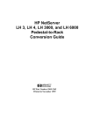
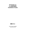
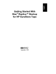
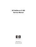
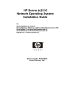
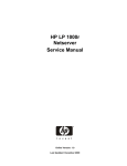
HP NetServer
LH 3000/3000r and
LH 6000/6000r
Mass Storage Upgrade Guide
HP Part Number 5969-2159
Printed in October 1999
Notice
The information contained in this document is subject to change without notice.
Hewlett-Packard makes no warranty of any kind with regard to this
material, including, but not limited to, the implied warranties of
merchantability and fitness for a particular purpose. Hewlett-Packard shall not
be liable for errors contained herein or for incidental or consequential damages in
connection with the furnishing, performance, or use of this material.
Hewlett-Packard assumes no responsibility for the use or reliability of its software
on equipment that is not furnished by Hewlett-Packard.
This document contains proprietary information that is protected by copyright. All
rights are reserved. No part of this document may be photocopied, reproduced, or
translated to another language without the prior written consent of
Hewlett-Packard Company.
Compaq® is a registered trademark of Compaq Computer Corporation.
3M® is a registered trademark of Minnesota Mining and Manufacturing Company.
Torx® is a registered trademark of Camcar Division of Textron, Inc.
Hewlett-Packard Company
Network Server Division
Technical Marketing / MS 45SLE
10955 Tantau Avenue
Cupertino, CA 95014 USA
© Copyright 1999, Hewlett-Packard Company.
Audience Assumptions
This guide is for the person who installs, administers, and troubleshoots network
servers. Hewlett-Packard Company assumes you are qualified in the servicing of
computer equipment and trained in recognizing hazards in products with
hazardous energy levels.
ii
Contents
1 Introduction ................................................................................................. 1
About This Guide........................................................................................... 1
Precautions ................................................................................................... 3
Verify Contents.............................................................................................. 4
Tools You Need............................................................................................. 5
Documents You May Need ............................................................................ 5
2 Installation ................................................................................................... 7
Installation Overview...................................................................................... 7
Step 1: Power Down and Disconnect ............................................................ 7
Step 2: Unlock and Remove Front Bezel....................................................... 8
Step 3: Remove Cover 1 and Cover Plate..................................................... 8
Step 4: Install Mass Storage Cage ................................................................ 9
Step 5: Remove I/O Fans............................................................................ 12
Step 6: Install SCSI Cable .......................................................................... 14
About Cabling the Secondary Cage ......................................................... 14
Cabling to I/O Baseboard SCSI B ............................................................ 15
Step 7: Connect Power Harness ................................................................. 18
Step 8: Replace I/O Fans............................................................................ 19
Step 9: Replace Cover 1 and Front Bezel ................................................... 20
Step 10: Install Hard Disk Drive Modules .................................................... 20
Hot-Swap Disk Drive Configurations ........................................................ 20
Installing Hot-Swap Drives....................................................................... 24
Step 11: Reconnect Power Cords and Other Cables................................... 24
Step 12: Verify Installation .......................................................................... 25
Verifying Hard Disk Drive Operation ........................................................ 25
3 Configure Mass Storage............................................................................ 29
About RAID or Non-RAID Operation ............................................................ 29
RAID Configuration...................................................................................... 30
Non-RAID Configuration .............................................................................. 30
Back Up Data .......................................................................................... 30
Run Setup Utility...................................................................................... 31
Run Symbios Configuration Utility............................................................ 35
Verify Disk Drive Modules........................................................................ 37
iii
Contents
A Warranty and Support ............................................................................... 39
Hardware Accessories Limited Warranty...................................................... 39
HP Repair and Telephone Support .............................................................. 39
B Regulatory Information ............................................................................. 41
Index............................................................................................................... 43
iv
1 Introduction
About This Guide
This guide contains instructions for installing an accessory second hot-swap mass
storage cage into your HP NetServer LH 3000 or LH 3000r, or your LH 6000 or
LH 6000r. The HP NetServer LH 3000 and the HP NetServer LH 6000 are the
floor-standing pedestal configurations, and the HP NetServer LH 3000r and the
HP NetServer LH 6000r are the rack-optimized configurations, as shown in Figure
1-1.
HP NetServer LH 3000r & LH 6000r
Rack-mount Configuration
HP NetServer LH 3000 & LH 6000
Pedestal Configuration
Figure 1-1. HP NetServer Configurations
NOTE
If you plan to install a duplex board on the second hot-swap
mass storage cage, do so before you install the cage. Refer to
HP NetServer Duplex Kit Installation Guide for instructions.
1
Chapter 1
Introduction
Chapter 2 of this guide tells how to install the second hot-swap mass storage cage
and its SCSI cable in the configuration shown in Figure 1-2.
I/O Baseboard
Non-Hot-Swap
SCSI Devices
SE Connector
SCSI A Connector
SCSI B Connector
Channel A
(Primary)
Channel B
(Secondary)
SCSI Cable for
Secondary Hot-Swap
Mass Storage Cage
Secondary Hot-Swap
Mass Storage Cage
(Left Drive Bay in
Pedestal Orientation)
Primary Hot-Swap
Mass Storage Cage
(Right Drive Bay in
Pedestal Orientation)
Figure 1-2. Cabling the Secondary Hot-Swap Mass Storage Cage
Chapter 3 tells how to configure the hot-swap disk drives.
Appendix A contains warranty and support information.
Appendix B contains regulatory information.
2
Chapter 1
Introduction
Precautions
Follow the procedures listed below to ensure safe handling of components and to
prevent harm to both you and the HP NetServer:
WARNING
Hazardous voltages and high energy levels are present inside
the HP NetServer. ALWAYS disconnect the AC power
cord(s) from the NetServer before removing the cover.
Serious injury may result if this warning is not observed.
WARNING
To prevent the rack from tipping over, extend the anti-tip foot
or attach the anti-tip feature before extending the
HP NetServer from the rack. Also lower the leveler feet of the
rack to improve stability and to prevent the rack from rolling.
Failure to use the anti-tip foot or feature and the leveler feet
could result in serious injury.
CAUTION
This accessory is sensitive to static electricity and can easily
be damaged by improper handling. Use of a grounding strap is
recommended. Read the following information carefully
before you handle the accessory:
• Leave the accessory in the anti-static container until you
are ready to install it.
• Use an anti-static service kit, such as 3M® 8501/8502/8505
or equivalent.
• Before you remove the accessory from the anti-static
container, touch a grounded, unpainted metal surface on
the system to discharge static electricity.
3
Chapter 1
Introduction
Verify Contents
CAUTION
An insulating sheet shown in Figure 1-3 covers the cage’s
backplane and part of one side. Leave it in place, and be
careful not to damage it.
Insulating
Sheet
Filler Panel
(5 places)
Figure 1-3. Front and Rear Views of Hot-Swap Mass Storage Cage
Unpack and verify the contents of the shipping box. This mass storage upgrade kit
contains the following:
• Hot-swap mass storage cage, shown in Figure 1-3
• Screws to mount the hot-swap mass storage cage
• SCSI cable to connect the hot-swap mass storage cage
• HP NetServer LH 3000/3000r and LH 6000/6000r Mass Storage Upgrade
Guide (this document)
If anything is missing or damaged, contact your reseller.
4
Chapter 1
Introduction
Tools You Need
The following materials are also required to install this upgrade:
• Anti-static Service Kit (3M part number 8501/8502/8505 or equivalent)
containing a wrist strap, anti-static mat, and cable. Use this kit to prevent
damage to the system from static electricity.
®
• T15 Torx driver
• T25 Torx driver (required for systems mounted in HP racks)
• HP NetServer Navigator CD-ROM (used for RAID configuration)
Documents You May Need
Refer to the following documents supplied with your HP NetServer:
• HP NetServer LH 3000/3000r Installation Guide
• HP NetServer LH 6000/6000r Installation Guide
• Integrated HP NetRAID Controller Configuration Guide
The HP NetServer Ultra2 SCSI Hot-swap Hard Disk Drive and Tray User Guide
is supplied with accessory Ultra2 SCSI hot-swap hard disk drives and trays.
The HP NetServer Duplex Board Installation Guide is supplied with the kit used
to install a duplex board.
For an HP NetServer installed in a Compaq rack, refer to the Installation Guide
for Compaq® 4000/7000 Racks for your HP NetServer.
The HP NetServer Online Documentation CD-ROM contains all of the documents
listed above.
5
2 Installation
Installation Overview
NOTE
If you plan to install a duplex board on the second hot-swap
mass storage cage, do so before you install the cage. Refer to
HP NetServer Duplex Kit Installation Guide for instructions.
Installing a second hot-swap mass storage cage in your HP NetServer requires
these general steps, which are described in this chapter:
• Step 1: Power Down and Disconnect
• Step 2: Unlock and Remove Front Bezel
• Step 3: Remove Cover 1 and Cover Plate
• Step 4: Install Mass Storage Cage
• Step 5: Remove Fan Assemblies
• Step 6: Install SCSI Cable
• Step 7: Connect Power Harness
• Step 8: Replace Fan Assemblies
• Step 9: Replace Cover 1 and Front Bezel
• Step 10: Install Hard Disk Drive Modules
• Step 11: Reconnect Power Cords and Other Cables
• Step 12: Verify Installation
After you finish the installation, go to Chapter 3 to configure your mass storage.
Step 1: Power Down and Disconnect
Do the following to power down and disconnect the HP NetServer:
1. Back up your system.
2. Bring down the network properly.
7
Chapter 2
Installation
3. Turn off power to the HP NetServer.
4. Disconnect the AC power cords and all external cables from the
HP NetServer.
WARNING
Before removing the cover, always disconnect the power
cord(s) and unplug telephone cables. Disconnect telephone
cables to avoid exposure to shock hazard from telephone
ringing voltages. Disconnect the power cord(s) to avoid
exposure to high energy levels that may cause burns when
parts are short-circuited by metal objects such as tools or
jewelry.
Note that the power switch does NOT turn off the standby
power. Disconnect the power cord(s) to turn off standby
power. If the backlight on the front panel LCD is still on,
standby power is still on.
Step 2: Unlock and Remove Front Bezel
To unlock and remove the front bezel, refer to the guides listed below that apply
to your HP NetServer configuration:
• HP NetServer LH 3000/3000r Installation Guide
• HP NetServer LH 6000/6000r Installation Guide
• The Installation Guide for Compaq® 4000/7000 Racks for your HP
NetServer
Step 3: Remove Cover 1 and Cover Plate
WARNING
If the HP NetServer is installed in a rack, extend the anti-tip
foot or attach the anti-tip feature before extending the
HP NetServer from the rack. Also lower the leveler feet of the
rack to improve stability and to prevent the rack from rolling.
Failure to use the anti-tip foot or feature and the leveler feet
could result in serious injury.
1. If the HP NetServer is installed in a rack, extend the HP NetServer from
the rack. Refer to your HP NetServer installation guide for instructions.
8
Chapter 2
Installation
2. Remove Cover 1 as described in your HP NetServer installation guide.
3. The HP NetServer has a cover plate on its chassis front over the expansion
bay in which you will install the mass storage cage. Unscrew its six
retaining screws, as shown in Figure 2-1, and remove the cover plate.
Figure 2-1. Remove Cover Plate
Store the cover plate and screws for future use, in case you ever remove the
second mass storage cage.
Step 4: Install Mass Storage Cage
NOTE
The secondary mass storage cage is shipped with filler panels
installed. Leave the filler panels in place while you install the
cage. Do not install hard disk drives before you install the cage.
If you are installing a hot-swap mass storage cage that already
contains hard disk drives, remove them before you install the
cage.
9
Chapter 2
Installation
1. Orient the hot-swap mass storage cage, as shown in Figure 2-2. The
backplane of the cage faces into the empty expansion bay. The connectors
on the cage’s backplane are near the edge closest to the CD-ROM drive.
CAUTION
As you insert the cage, be careful not to damage the insulating
sheet covering the cage’s backplane and part of one side.
Insulating Sheet
Filler Panel (5 places)
Insulating Sheet
Filler Panel (5 places)
Figure 2-2. Orient and Insert the Hot-Swap Mass Storage Cage
2. Insert the hot-swap mass storage cage by sliding it carefully into the mass
storage expansion bay, as shown in Figure 2-2.
NOTE
If you are installing a secondary mass storage cage that has a
duplex board installed, connect the appropriate SCSI cables
now, before the cage is fully installed. This gives you easier
access to the SCSI connectors. Refer to the HP NetServer
Duplex Kit Installation Guide for instructions.
3. When the cage is correctly positioned, press it firmly into place, so that its
flanges are flush with the chassis front.
10
Chapter 2
Installation
4. Using the two circular access holes in the chassis shown in Figure 2-3,
insert and tighten two screws supplied with the upgrade kit.
◊
HP NetServer LH 3000 and LH 6000 access holes are on the side of the
chassis.
◊
HP NetServer LH 3000r and LH 6000r access holes are on the top of
the chassis.
Figure 2-3. Insert and Tighten Two Screws (1),
and Then Insert and Tighten Six Screws (2)
5. Insert six screws into the front of the hot-swap mass storage cage, as
shown in Figure 2-3, and tighten them.
11
Chapter 2
Installation
Step 5: Remove I/O Fans
Before you install the SCSI cable, remove the two I/O fans to gain working space
and access to the SCSI B connector on the I/O baseboard.
To remove the I/O fans, refer to Figure 2-4 or 2-5. Grasp one of the I/O fan
modules, depress the latch on the back of the module, and pull the module straight
out from the HP NetServer. Repeat this for the other I/O fan.
Latches on
I/O Fans
Thumbscrew
on Air Baffle
Figure 2-4. Remove I/O Fan from HP NetServer in Pedestal Configuration
12
Chapter 2
Installation
Latches on
I/O Fans
Thumbscrew
on Air Baffle
Figure 2-5. Remove I/O Fans from Rack-Mounted HP NetServer
NOTE
To improve access to the back of the secondary hot-swap mass
storage cage, you can remove the air baffle indicated in
Figures 2-4 and 2-5. To remove it, loosen the thumbscrew, and
pull the air baffle away from the HP NetServer. Be sure to
reinstall the air baffle before reattaching Cover 1.
13
Chapter 2
Installation
Step 6: Install SCSI Cable
About Cabling the Secondary Cage
The HP NetServer is normally shipped with the primary mass storage cage
connected to the SCSI A connector on the I/O baseboard. The secondary mass
storage cage can be connected to the SCSI B connector on the I/O baseboard if
that connector is unused. The hot-swap mass storage cages cannot be daisychained; that is, they cannot be connected to each other or to other mass storage
devices.
NOTE
Do not use a terminated SCSI cable on either hot-swap mass
storage cage.
The SCSI A and SCSI B channels on the I/O baseboard can both be set to
integrated HP NetRAID (RAID) or LVD SCSI (non-RAID) operation, but both
channels must operate in the same mode, RAID or non-RAID. For more
information on RAID, see Chapter 3.
l To operate both mass storage cages as RAID, connect the secondary
mass storage cage to the SCSI B connector on the I/O baseboard. Refer to
"Cabling to I/O Baseboard SCSI B" below for instructions.
l To operate both mass storage cages as non-RAID, connect the
secondary mass storage cage to the SCSI B connector on the I/O
baseboard. Refer to "Cabling to I/O Baseboard SCSI B" below for
instructions.
l To operate one mass storage cage as RAID and the other as nonRAID, only connect one cage to the I/O baseboard. Install an accessory
SCSI host bus adapter or an HP NetRAID series adapter to control the
mass storage cage not connected to the I/O baseboard.
NOTE
14
If a duplex board is installed in the primary or secondary mass
storage cage, refer to the HP NetServer Duplex Kit Installation
Guide for cabling information.
Chapter 2
Installation
Cabling to I/O Baseboard SCSI B
To connect the secondary mass storage cage to the SCSI B connector on the I/O
baseboard, install the SCSI cable supplied with the kit as follows:
1. Carefully pull aside the cables for the flexible disk drive and CD-ROM
drive to gain access to the SCSI B connector on the I/O baseboard, which
is shown in Figure 2-6. Handle these cables carefully to avoid accidentally
disconnecting them.
SCSI A Connector
SCSI Cable
SCSI B Connector
Figure 2-6. Connect SCSI Cable to I/O Baseboard’s SCSI B Connector
15
Chapter 2
Installation
2. Connect the SCSI cable’s 68-pin connector labeled "To I/O Board" to the
SCSI B connector on the I/O baseboard, as shown in Figure 2-6.
To attach the 68-pin connector, press on the center of the connector strain
relief and press the connector into place, as shown in Figure 2-7. Two
clicks indicates the connector is properly installed.
Figure 2-7. Attach SCSI Cable Connector
16
Chapter 2
Installation
3. Connect the SCSI cable’s 68-pin connector labeled "To SCSI Mass Storage
Device" to the SCSI connector on the cage’s backplane, as shown in Figure
2-8.
Figure 2-8. Attach SCSI Cable Connector to Cage’s Backplane
17
Chapter 2
Installation
Step 7: Connect Power Harness
1. Orient the connector labeled P2 on the power harness to the power socket
on the backplane of the mass storage cage, as shown in Figure 2-9.
Figure 2-9. Connect Power Harness to Backplane of Mass Storage Cage
2. Connect the P2 connector on the power harness to the power socket on the
backplane of the mass storage cage. Verify that the latch on the connector
is seated.
18
Chapter 2
Installation
Step 8: Replace I/O Fans
The two I/O fan modules are identical. Replace them as follows:
1. Orient one I/O fan to the accessory board guide, as shown in Figure 2-10.
Accessory Board Guide
I/O Fan
I/O Fan
Figure 2-10. Insert Fan Assemblies (Shown for Pedestal Configuration)
2. Insert the fan module and press it firmly into the connector.
3. Repeat Steps 1 and 2 for the other I/O fan.
19
Chapter 2
Installation
Step 9: Replace Cover 1 and Front Bezel
NOTE
If you removed the air baffle indicated in Figure 2-4 or 2-5,
replace it now, before you replace Cover 1.
1. Replace Cover 1 as described in your HP NetServer installation guide.
2. If the HP NetServer is mounted in a rack, slide the HP NetServer into the
rack, and secure the HP NetServer to the rack, as described in the
installation guide or rack documentation.
3. Install the front bezel as described in the installation guide or rack
documentation. Lock the front bezel.
4. After the HP NetServer is secured in a rack with an anti-tip foot, you can
retract the anti-tip foot if desired.
Step 10: Install Hard Disk Drive Modules
Hot-Swap Disk Drive Configurations
NOTE
20
If a duplex board is installed in the secondary mass storage
cage, refer to the HP NetServer Duplex Kit Installation Guide
or your HP NetServer installation guide for drive
configurations and SCSI addresses (IDs).
Chapter 2
Installation
Before you install the hot-swap disk drive modules, decide where to place them in
the secondary mass storage cage. Figure 2-11 shows the drive blockers, which
prevent installation of drive modules into unsupported positions.
Drive Blockers
prevent installation
of drive modules into
unsupported positions
Figure 2-11. Drive Blockers in Hot-Swap Mass Storage Cage
NOTE
SCSI addresses (IDs) in the secondary hot-swap mass storage
cage are different from and independent of SCSI addresses in
the primary cage. SCSI addresses for devices in both cages for
single-bus and dual-bus configurations are shown in your
HP NetServer installation guide and the HP NetServer Duplex
Kit Installation Guide.
21
Chapter 2
Installation
Below are single-bus (no duplex board) hot-swap drive configurations and SCSI
addresses (IDs) for the secondary cage in a pedestal HP NetServer. Load drive
modules with all necessary drive spacers starting at the bottom of the cage, as
described in "Installing Hot-Swap Drives" later in this chapter. Filler panels must
occupy all locations without disk drive modules.
15
15
Drive Spacer
14
Drive Spacer
13
12
12
Drive Spacer
11
10
Load
Drive Spacer
10
15
14
14
Drive Spacer
Drive Spacer
12
12
Drive Spacer
Drive Spacer
10
Load
10
15
15
14
14
13
13
12
12
Drive Spacer
11
10
10
Load
Figure 2-12. SCSI IDs for Single-Bus Configurations in Pedestal Orientation
22
Chapter 2
Installation
Below are single-bus (no duplex board) hot-swap drive configurations and SCSI
addresses (IDs) for the secondary cage in a rack-mounted HP NetServer. Load
drive modules with all necessary drive spacers starting at the bottom of the cage,
as described in "Installing Hot-Swap Drives" later in this chapter. Filler panels
must occupy all locations without disk drive modules.
Drive Spacer
Drive Spacer
10 11 12 13 14 15
Load
10
10
12
Drive Spacer
14
Load
12 13 14 15
Drive Spacer
10
10 11
Drive Spacer
12
14 15
Load
12
14 15
Drive Spacer
Drive Spacer
10
12 13
15
Drive Spacer
Drive Spacer
Figure 2-13. SCSI IDs for Single-Bus Configurations in Rack Orientation
23
Chapter 2
Installation
Installing Hot-Swap Drives
CAUTION
Protect the drive from static electricity by leaving it in its antistatic bag until you are ready to install it. Before handling the
drive, touch any unpainted metal surface to discharge static
electricity. When you remove the drive from the anti-static
bag, handle it only by the frame.
Do not touch the electrical components. Place the drive on the
anti-static bag whenever you set it down.
If the secondary hot-swap mass storage cage is locked, unlock it with its key.
Refer to the HP NetServer Ultra2 SCSI Hot-swap Hard Disk Drive and Tray User
Guide, and install the disk drive modules into the secondary hot-swap mass
storage cage. Install all required drive spacers and filler panels.
• Remove filler panels from the secondary hot-swap mass storage cage at the
positions where you plan to install disk drive modules.
• Filler panels must occupy all empty disk drive locations in the hot-swap
mass storage cage.
• Drive spacers must be installed to fill all empty spaces between adjacent
disk drive modules or filler panels in the hot-swap mass storage cage.
• Insert disk drive modules in the order shown by the "Load" arrow in
Figure 2-12 or 2-13. Insert them slowly and gently to prevent damage, as
described in HP NetServer Ultra2 SCSI Hot-swap Hard Disk Drive and
Tray User Guide.
CAUTION
Do NOT operate the HP NetServer with any missing drive
spacers or filler panels. Otherwise, overheating can damage
disk drive modules.
Step 11: Reconnect Power Cords and Other
Cables
1. Reconnect the AC power cords and any other external cables.
2. Attach the power cord retainer for each AC power cord, as shown in your
HP NetServer installation guide.
24
Chapter 2
Installation
Step 12: Verify Installation
Verify the installation of the second hot-swap mass storage cage and the drives in
it. To do so, verify that all of the hot-swap drives are operational by using one of
the following:
l Hard disk drive LEDs: See "Verifying Hard Disk Drive Operation"
below.
l HP DiagTools: Run this diagnostic utility to verify the hard disk drive
modules. Refer to your HP NetServer’s installation guide, or download HP
DiagTools and its guide.
To download, go to http://www.hp.com/go/netserver/, select
Technical Support, and then select Troubleshooting. Download the latest
version of HP DiagTools and the guide for it.
Verifying Hard Disk Drive Operation
Each Ultra2 hard disk drive module has two LED indicators on its front, one for
status and one for activity, as shown in Figure 2-14.
Status LED
Indicator
Activity LED
Indicator
Figure 2-14. LED Apertures on Ultra 2 Hard Disk Drive Module
25
Chapter 2
Installation
Light pipes on the module transmit light to these apertures from LEDs on the
inside rear of the hot-swap mass storage cage. Verify that the LEDs show the
correct status and activity indications for all of the disk drive modules that you
installed:
1. Turn on power to the HP NetServer and display monitor.
2. During the Power On Self Test (POST) early in the boot sequence, watch
the two LED indicators on each hard disk drive module.
◊
Status LEDs: All LEDs quickly cycle from amber to steady green.
◊
Activity LEDs: All LEDs quickly cycle from amber to green. The
LED stays steady green until the drive spins up.
3. If no LED indicators were illuminated on any disk drive modules, the
power harness may not be correctly connected. Check it as follows:
a. Turn off the HP NetServer power switch and unplug the AC power
cords and any telephone cables. Remove the front bezel and Cover 1, as
described in Steps 1 and 2. Remove the fan assemblies as described in
Step 5.
b. Disconnect the P2 connector of the power harness, and reconnect it as
described in Step 7.
c. Replace the fan assemblies as described in Step 8. Replace Cover 1 and
the front bezel as described in Step 9. Reconnect the AC power cords
and any telephone cables.
d. Restart the HP NetServer to determine whether the LED indicators
become illuminated during the POST now. If not, contact your reseller.
26
Chapter 2
Installation
4. If one or both LED indicators on a single module are not illuminated
during the POST, the module may be installed incorrectly, or its light pipes
(shown in Figure 2-15) may be damaged.
Light Pipes
Figure 2-15. LED Light Pipes on Ultra 2 Hard Disk Drive Module
(Shown for Low-Profile Disk Module)
Check the light pipe on the module as follows:
a. Remove the disk drive module, as described in the HP NetServer
Ultra2 SCSI Hot-swap Hard Disk Drive and Tray User Guide.
b. Inspect the light pipes, shown in Figure 2-15, for damage. If a light
pipe is damaged, contact your reseller.
CAUTION
The light pipes are fragile. Be careful not to damage them
when you inspect them or when you reinsert the module.
c. Reinstall the disk drive module, as described in the HP NetServer
Ultra2 SCSI Hot-swap Hard Disk Drive and Tray User Guide.
d. Restart the HP NetServer to determine whether the LED indicators
become illuminated during the POST now. If not, contact your reseller.
27
3 Configure Mass Storage
About RAID or Non-RAID Operation
The disk drives in the hot-swap mass storage cages can be configured in one of
two different modes:
• RAID configuration: RAID (Redundant Array of Independent Disks)
configuration can enhance performance and provide fault tolerance
(redundancy).
◊
RAID is the factory default for SCSI channels A and B on the I/O
baseboard.
◊
For more information about RAID, see the Integrated HP NetRAID
Controller Configuration Guide.
◊
Some Network Operating Systems (NOSs) cannot be installed on a
RAID logical drive.
◊
RAID configuration is described in "RAID Configuration" later in this
chapter.
• Non-RAID configuration: Non-RAID configuration (also called "JBOD"
or "Just a Bunch of Disks" configuration) is quick and easy.
◊
All NOSs supported by your HP NetServer can be installed on
non-RAID hard disk drives.
◊
Non-RAID configuration is described in "Non-RAID Configuration"
later in this chapter.
NOTE
All hard disk drives connected to SCSI A and SCSI B on the
I/O baseboard must be configured in the same mode, either all
as RAID, or all as non-RAID.
29
Chapter 3
Configure Mass Storage
RAID Configuration
To configure the secondary hot-swap mass storage cage for RAID operation, refer
to one of the following:
l If you connected the secondary hot-swap mass storage to SCSI A or
SCSI B on the I/O baseboard, refer to the Integrated HP NetRAID
Controller Configuration Guide.
l If you connected the secondary hot-swap mass storage to an HP NetRAID
Series adapter, refer to the HP NetRAID Series Installation and
Configuration Guide.
HP NetRAID supports Ultra2 SCSI. To ensure that Ultra2 SCSI support is
enabled for the secondary hot-swap mass storage cage, run HP NetRAID Express
Tools. For instructions, refer to one of the guides listed above.
Non-RAID Configuration
Drives in the secondary hot-swap mass storage cage can be controlled in
non-RAID mode by the SCSI controllers on the I/O baseboard or by a separate
SCSI host bus adapter board installed in a PCI slot.
l If you connected the secondary hot-swap mass storage cage to a SCSI host
bus adapter, refer to its documentation for configuration information.
l If you connected the secondary hot-swap mass storage cage to the SCSI A
or SCSI B connector on the I/O baseboard, do the following to
configure non-RAID operation:
◊
Back up all data on the HP NetServer.
◊
Verify non-RAID operation and the boot order by running the Setup
utility, as described in "Run Setup Utility" later in this chapter.
◊
Verify the display, operation, and boot order of the SCSI channels, as
described in "Run Symbios Configuration Utility" later in this chapter.
◊
Verify the secondary hot-swap mass storage cage installation and the
disk drive module installation, as described in "Verify Disk Drive
Modules" later in this chapter.
Back Up Data
Before you change the configuration of your mass storage, back up all data on the
HP NetServer and any external enclosures connected to it.
30
Chapter 3
Configure Mass Storage
Run Setup Utility
Use the Setup utility to verify non-RAID (LVD SCSI) control of SCSI channels A
and B and to verify the boot device priority and the priority of various hard disk
drive controllers within the boot device priority.
NOTE
To set the boot priority of hard disk drive controllers, also use
the Symbios Configuration Utility to set the channel to be
searched first for a bootable drive, as described in "Run
Symbios Configuration Utility" in later this chapter.
Start Setup Utility
1. If the HP NetServer and display monitor are not on already, turn on power
to them. Start or restart the HP NetServer.
If you receive an error message during the boot process, refer to
"Troubleshooting" in the HP NetServer installation guide or the online
help. Some power-up (boot) messages are routine.
31
Chapter 3
Configure Mass Storage
NOTE
The message "Configuration of NVRAM and drives mismatch"
indicates that configuration information in the integrated HP
NetRAID controller’s NVRAM differs from configuration
information in hard disk drives.
Do the following to clear configuration information from
integrated HP NetRAID NVRAM:
1. Press Ctrl+M to start the HP NetRAID Express Tools utility.
2. On the Tools Management Menu, choose Configure.
3. On the Configure menu, choose Clear Configuration.
• If the question "Clear Configuration?" is displayed, answer
Yes. Then press any key to continue, and go to Step 4 in
this note.
• If the message "No Existing Configuration to Clear" is
displayed, press Esc to return to the Configuration menu,
choose New Configuration, and answer Yes to the
question "Proceed?". When the scan finishes, all drives are
shown in the Ready state. Press Enter to end the array, and
answer Yes to the "Save Configuration?" question. When
"Configuration is Saved" is displayed, press any key.
4. To exit HP NetRAID Express Tools, press ESC repeatedly
until the Exit? box appears. Choose YES to exit. Then press
Ctrl+Alt+Del to restart the NetServer.
2. As soon as you see the message
Press <F2> to enter SETUP
on the display monitor, press the F2 function key.
NOTE
If you wait too long to press the F2 function key, you may not
be able to enter the Setup utility, even though the message
"Press <F2> to enter SETUP" is still displayed. If this happens,
restart the HP NetServer, and press the F2 function key as soon
as the message appears.
3. If a power-on password has been set, provide it when prompted.
32
Chapter 3
Configure Mass Storage
4. When the Setup Utility menu is first displayed, the Configuration menu is
also displayed. (If the Configuration menu is not displayed, use the left
arrow key to highlight Configuration on the Main menu.)
The system time and system date are displayed. If either needs to be
changed, use the down arrow on the keyboard to highlight the item. Then
follow the instructions on the screen.
Verify Boot Order
5. On the Configuration menu, use the up and down arrows to highlight Boot
Settings, and press Enter to choose it.
6. On the Boot Settings submenu, use the up and down arrows to highlight
Boot Device Priority, and press Enter to choose it.
7. The Boot Device Priority list displays the order in which device types will
be searched for a bootable device.
If you need to change the priorities, follow the on-screen instructions.
When the boot device priorities are correct, press Esc to return to the Boot
Settings submenu.
8. On the Boot Settings submenu, use the up and down arrows to highlight
Hard Drive Priority, and press Enter to choose it.
9. The Hard Drive Priority list displays the order in which hard disk drive
controllers will be searched for a bootable device.
If you need to change the priorities, follow the on-screen instructions.
When the hard drive priorities are correct, press Esc twice to return to the
Configuration menu.
Verify That LVD SCSI Is Enabled
10. On the Configuration menu, use the down arrow key to highlight
Embedded LAN and SCSI Settings. Then press Enter.
33
Chapter 3
Configure Mass Storage
11. The Embedded LAN and SCSI Settings submenu is displayed. If
HP NetRAID/LVD SCSI is not already highlighted, use the up and down
arrows to highlight it.
Read the values in the brackets to determine whether LVD SCSI is
enabled.
◊
Enable LVD SCSI indicates that LVD SCSI is enabled and
HP NetRAID is disabled. This is the correct setting for non-RAID
operation of the mass storage cages connected to SCSI A and B on the
I/O baseboard.
◊
Enable HP NetRAID indicates that HP NetRAID is enabled to
provide RAID operation of the mass storage cages connected to
SCSI A and B on the I/O baseboard. This is the default value.
CAUTION
If your HP NetServer was previously operating in RAID mode
(Enable HP NetRAID), changing to non-RAID mode (Enable
LVD SCSI) could cause data loss. Be sure your data is backed
up before you change to non-RAID mode.
If the value is not Enable LVD SCSI, use the +/- keys to change it to
Enable LVD SCSI. This change will take effect when the HP NetServer
restarts.
Exit Setup Utility
12. Press the F10 function key to save and exit.
13. In the Setup Confirmation dialog box, press Enter to answer "Yes" to the
question, "Save configuration changes and exit now?" The HP NetServer
will restart.
34
Chapter 3
Configure Mass Storage
Run Symbios Configuration Utility
NOTE
Run the Symbios Configuration utility to do the following:
• To verify that devices on SCSI channels A and B are
displayed on the boot screen.
• To verify that the controllers of SCSI channels A and B are
set "On" to operate.
• To verify that both SCSI channels A and B are searched
for a bootable drive.
• To control the order in which SCSI channels A and B are
searched for a bootable drive.
Do the following to run the Symbios Configuration utility:
1. Restart the HP NetServer.
If you receive an error message during the boot process, refer to
"Troubleshooting" in the HP NetServer LH 3000/3000r or LH 6000/6000r
Installation Guide(s) or the online help. Some power-up (boot) messages
are routine.
2. As soon as you see the message
Press Ctrl-C to start Symbios Configuration
Utility...
on the display monitor, press the Ctrl+C keys.
NOTE
If SCSI A and B on the I/O baseboard are operating in RAID
mode, the prompt to press CTRL+C is not displayed. To
change to non-RAID mode, refer to "Run Setup Utility".
If you wait too long to press the Ctrl+C keys, you may not be
able to enter the Symbios Configuration utility, even though
the message "Press Ctrl-C to start Symbios Configuration
Utility..." is still displayed. If this happens, restart the
HP NetServer, and press the Ctrl+C keys as soon as the
message appears.
35
Chapter 3
Configure Mass Storage
3. When the Symbios Logic SCSI Configuration Utility Main Menu is
displayed, verify that shows Display=Verbose. (This means that the nonRAID SCSI devices will be listed on the boot screen.)
If not, use the up and down arrow keys to highlight Display=Terse. Press
Enter to change the setting to Verbose.
4. On the Symbios Logic SCSI Configuration Utility Main Menu, verify that
the Current Status of all Symbios controllers (adapters) is On.
If not, use the up and down arrow keys to highlight Change Adapter
Status. Press Enter to display the Change Status on Next Boot window.
Use the up and down arrow keys to highlight the controller, and press
Enter to change its Next-Boot Status to On. Press Esc to return to the Main
Menu.
5. On the Symbios Logic SCSI Configuration Utility Main Menu, use the up
and down arrow keys to highlight Adapter Boot Order. Press Enter to
select it.
6. The Adapter Boot Order screen displays the two SCSI controllers and
numbers representing their boot order in the following form:
Boot
Boot
Order
m
SYM53C896
Bus
DevFunc
04
28
Order
n
SYM53C896
Bus
DevFunc
04
29
where m and n are the numbers 0 or 1 or a blank.
The number in the m position indicates the boot order of the SCSI A
controller, and the number in the n position indicates the boot order of the
SCSI B controller.
◊
0 marks the controller of the SCSI channel searched first for a bootable
drive.
◊
1 marks the controller of the SCSI channel searched second for a
bootable drive.
◊
A blank indicates that the controller’s SCSI channel is not searched for
a bootable drive.
To add or change a boot order sequence number, use the right and left
arrow keys to highlight the controller, and then press Enter. Type the new
sequence number (0 or 1), and press Enter. The boot order sequence
number of the other controller will change, if necessary. 0 must be
assigned to a controller before 1 can be assigned to the other controller.
36
Chapter 3
Configure Mass Storage
To remove a controller from the boot order, use the right and left arrow
keys to highlight the controller, and then press Enter twice. (This creates a
blank.) The boot order sequence number of the other controller will change
to 0, if necessary.
7. Press Esc to return to the Main Menu. To begin to exit the utility, use the
up and down arrow keys to highlight Quit, and press Enter. When the
message
Rebooting system to change global settings...
Press any key
is displayed, press any key to exit the Symbios Configuration utility and
restart the HP NetServer.
Verify Disk Drive Modules
As the HP NetServer restarts, watch the display monitor to determine whether all
the drives you installed have been detected.
NOTE
Any SCSI devices controlled by the integrated HP NetRAID
controller will NOT be displayed during the boot process.
Any SCSI devices controlled by a SCSI controller without a
boot order number will NOT be displayed during the boot
process.
If no drives in the secondary hot-swap mass storage cage are detected, refer to
Chapter 2 as you do the following:
1. Turn off power to the HP NetServer, and unplug the AC power cord(s).
2. Remove Cover 1.
3. Verify that the power harness is connected correctly to the cage.
4. Verify that the SCSI cable is connected correctly to the cage.
5. Remove the I/O fans to view the SCSI B connector on the I/O baseboard.
Verify that the SCSI cable is connected correctly to the SCSI B connector
on the I/O baseboard.
6. Replace the I/O fans.
7. Replace Cover 1.
8. Reconnect the AC power cord(s), and restart the HP NetServer.
37
Chapter 3
Configure Mass Storage
9. Watch the display monitor for the boot listing of SCSI devices to
determine whether all the drives you installed have been detected.
If one drive was not detected, refer to the HP NetServer Ultra2 SCSI Hot-swap
Hard Disk Drive and Tray User Guide as you do the following:
1. Determine which drive was not detected. Do this by comparing the SCSI
addresses (IDs) of the detected drives with the SCSI addresses in "About
SCSI Addresses in Secondary Cage" in Chapter 2 of this guide. (This drive
and its module are referred to as "suspect" in the actions below.)
2. To verify that the module is properly seated, remove the suspect module,
and then reinstall it.
3. To determine whether the mass storage cage may be defective, restart the
HP NetServer, and see whether the suspect drive is detected.
◊
If the suspect drive is detected, the problem is solved.
◊
If the suspect drive is not detected, swap the suspect module for
another module that was detected in another position, restart the
HPNetServer, and see whether either of those two drives are detected.
∗ If the suspect drive is detected in its new position, the secondary
hot-swap mass storage cage may be defective. Contact your
reseller.
∗ If the other drive (in the module swapped for the suspect module)
is not detected in its new position, the secondary hot-swap mass
storage cage may be defective. Contact your reseller.
∗ If the suspect drive is not detected in its new position, go to action
4 below.
4. The suspect drive was not detected, even in another position:
◊
If you purchased the disk drive module already assembled, the module
may be defective. Contact your reseller.
◊
If you installed the disk drive into the tray, check that installation.
Refer to the HP NetServer Ultra2 SCSI Hot-swap Hard Disk Drive and
Tray User Guide to do the following: remove the module from the
cage; reinstall the disk drive into the tray, and reinstall the module into
the cage. Restart the HP NetServer to see if the drive is detected.
∗ If so, the problem is solved.
∗ If not, the disk drive or the tray may be defective. Contact your
reseller.
38
A Warranty and Support
Refer to the HP NetServer Warranty and Service/Support Booklet provided with
your original HP NetServer system documentation for the warranty limitations,
customer responsibilities, and other terms and conditions.
Hardware Accessories Limited Warranty
An HP NetServer Hardware Accessory is an HP hardware product that is
specifically designated for use with HP NetServers; is added on or integrated into
an HP NetServer in order to provide higher performance, capacity, or increased
capability; and is listed as a product in HP’s Corporate Price List. Upon
installation inside an HP NetServer, the HP NetServer Hardware Accessory
carries a System-Matching Warranty. This warranty includes a one-year Returnto-HP warranty or the remainder of the warranty period for the original
HP NetServer in which it is installed, whichever is longer.
This accessory may be serviced through expedited part shipment. In this event, HP
will prepay shipping charges, duty, and taxes; provide telephone assistance on
replacement of the component; and pay shipping charges, duty, and taxes for any
part that HP asks to be returned.
HP warrants this HP NetServer Hardware Accessory against defects in material
and workmanship, under normal use. The warranty commences on receipt of this
product by Customer from HP or Reseller. If HP or Reseller receives notice of
such defects during the warranty period, HP or Reseller will either, at its option,
repair or replace products that prove to be defective.
Should HP or Reseller be unable to repair or replace the hardware accessory
within a reasonable amount of time, Customer’s alternate remedy shall be a refund
of the purchase price upon return of the hardware accessory product. The
customer may be required to run HP-supplied configuration and diagnostic
programs before a replacement will be dispatched or an on-site visit is authorized.
HP Repair and Telephone Support
Refer to the HP NetServer Warranty and Service/Support Booklet supplied with
your HP NetServer system documentation for instructions on how to obtain HP
repair and telephone support.
39
B Regulatory Information
DECLARATION OF CONFORMITY
according to ISO/IEC Guide 22 and EN 45014
Manufacturer’s Name:
Address:
Hewlett-Packard Company
10955 Tantau Avenue
Cupertino, CA 95014 USA
declares, that the product
Product Name:
Second Drive Cage
Model Number(s):
D9158A
Product Options:
N/A
conforms to the following Product Specifications:
Safety:
IEC 950:1991+A1+A2+A3+A4/ EN 60950: 1992+A1+A2+A3+A4+A11
GB4943-1995
EMC:
CISPR 22:1993+A1+A2/ EN 55022:1994+A1+A2 - Class B 1
EN 50082-1:1992 - Generic Immunity
IEC 801-2:1991, 4 kV CD, 8 kV AD
IEC 801-3:1984, 3V/m
IEC 801-4:1988, 0.5 kV Signal Lines, 1 kV Power Lines
FCC Title 47 CFR, Part 15
Supplementary Information:
1) The product was tested in a typical configuration with a Hewlett-Packard NetServer computer and
peripherals.
2) The product complies with Part 15 of the FCC rules. Operation is subject to the following two
conditions:
• This device may not cause harmful interference, and
• This device must accept any interference received, including interference that may cause
undesired operation.
The product herewith complies with the requirements of the following directives, and carries the CEmark accordingly:
o EMC Directive 89/336/EEC
o Low Voltage Directive 73/23/EEC
Cupertino, June 10, 1999
Erin McLaughlin NSD Regulatory Manager
North American Contact: Hewlett-Packard Company Product Regulation Manager, 3000 Hanover Street, Palo
Alto, CA 94304, USA [Telephone: (650) 857-1501]
European Contact: Your local Hewlett-Packard Sales and Service Office or Hewlett-Packard GmbH,
Department ZQ / Standards Europe, Herrenberger Straße 130, D-71034 Böblingen (FAX: + 49-7031-143143)
41
Index
A
Access holes, 11
Activity LED, 25
Adapter boot order, 36
Anti-static precautions, 3, 5
Anti-tip foot, 20
B
Back up data, 30
Backplane, cage’s, 4
Bezel, front, 8, 20
Boot device priority, 31
Boot Device Priority, 33
Boot order, 33, 36
Boot Settings, 33
C
Caution
anti-static, 3
insulating sheet, 4, 10
light pipes, 27
thermal damage, 24
Clear (reset) configuration, 32
Compaq rack, 5
Configuration menu, 33
Configure menu, 32
Configuring mass storage, 29
non-RAID, 30
RAID, 30
Contents of kit, 4
Cover plate, 9
D
Default settings, 34
Disconnecting the HP NetServer, 7
Disk drives
configuring, 29
verifying, 37
Documents, 5
Drive spacers, 24
E
Embedded LAN and SCSI Settings, 34
Environmental specifications, 41
Error message, 31, 32, 35
Exiting
HP NetRAID Express Tools, 32
Setup utility, 34
Symbios Configuration utility, 37
F
Fans, I/O, 12, 19
Filler panels, 24
Front bezel, 8, 20
G
Getting help, 39
H
Hard Drive Priority, 33
Hardware accessories limited warranty,
39
Hardware repair
warranty information for, 39
Help, 39
Hot-swap disk drive module, 25
Hot-swap disk drive moduless
installing, 20
Hot-swap mass storage cage
configuring, 29
features, 4
installing, 7, 10
verifying, 38
HP NetRAID Express Tools, 32
Clear Configuration, 32
Configure menu, 32
Management Menu, 32
Ultra2 SCSI, 30
HP NetServer LH 3000, 1
HP NetServer LH 3000r, 1
HP NetServer LH 6000, 1
HP NetServer LH 6000r, 1
43
Index
I
I/O baseboard, 12, 15
I/O fans, 12, 19
Indicators, LED, 26
Insulating sheet, 4, 10
K
Kit contents, 4
L
LEDs, 25
Light pipes, LED, 27
LVD SCSI, 34
M
Management Menu, 32
N
Non-RAID configuration, 29, 30
NVRAM, 32
P
Power cord retainer, 24
Power harness, 18
Powering down the HP NetServer, 7
R
RAID configuration, 29, 30
Regulatory information, 41
Reset (clear) configuration, 32
S
SCSI B connector, 12, 15
SCSI cable, 15
Setup utility, 33
exiting, 34
starting, 31
Standby power, 8
44
Status LED, 25
Symbios Configuration utility, 35
adapter boot order, 36
Display, 36
exiting, 37
starting, 35
T
Tools, 5
U
Ultra2 hard disk drive modules, 25
Ultra2 SCSI, 30
Utilities
HP NetRAID Express Tools, 30, 32
Setup, 31, 33
Symbios Configuration, 35, 36
V
Verifying
boot order, 33
cage installation, 38
disk drives, 37
kit contents, 4
LVD SCSI enabled, 33
non-RAID boot order, 35
SCSI B Channel control, 31
W
Warning
anti-tip, 3, 8
hazardous voltages, 3
shock hazard, 8
Warranty
for hardware, 39
hardware accessories limited, 39